

High Strength Steel Cylinders for
Transporting Hydrogen-Bearing GasesHazMat R&D Forum
May 16, 2018
Washington DC
AJ Slifka, ES Drexler,
MJ Connolly, PE Bradley, ML
Martin, DS Lauria
NIST, Boulder, CO
RL Amaro
University of Alabama
CP Looney
Colorado School of Mines
M Rana, J Smith
Consultants
M Toughiry
DOT
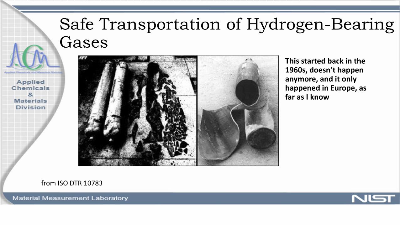
Safe Transportation of Hydrogen-Bearing Gases
This started back in the 1960s, doesn’t happen anymore, and it only happened in Europe, as far as I know
from ISO DTR 10783
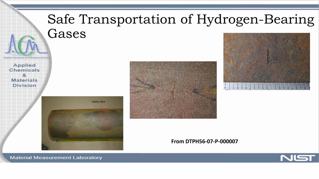
Safe Transportation of Hydrogen-Bearing Gases
From DTPH56-07-P-000007
Safe Transportation of Hydrogen-Bearing Gases
Can higher-strength steels be used?
• Strain-Life measurements
• Modeling of full elastic and plastic effects
• Fatigue results from SNL?
How “safe” are each of the three test methods in ISO 11114-4?
• Strain-Life measurements• Baseline material (UTS=724 MPa)• High-strength material (UTS – 1040
MPa)
• Modeling• Elastic effects• Accumulated inelastic strain• Comparison of A, B, C methods• Microstructure
• Crack-tip mechanics
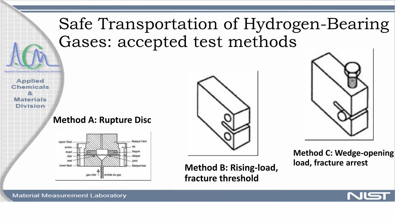
Safe Transportation of Hydrogen-Bearing Gases: accepted test methods
Method A: Rupture Disc
Method C: Wedge-opening load, fracture arrest
Method B: Rising-load, fracture threshold

Strain-Life Measurements: 4130 steel
Raw Datastrain rate 0.008 forall measurements
ε=0.0098f=0.2HzR=-1air

Strain-Life Measurements: 4130 steel
0
100
200
300
400
500
600
700
0 0.002 0.004 0.006 0.008 0.01
Stre
ss (
Mp
a)
Strain (-)
ABAQUS N=0.5 NoIsotropic
Raw Data N=0.5
AirFirst Cycle- MonotonicElastic-perfectly plastic behavior is ignored

Strain-Life Measurements: 4130 steel
-800
-600
-400
-200
0
200
400
600
800
-0.01 -0.005 0 0.005 0.01
Stre
ss (
Mp
a)
Strain (-)
N=1 Raw Data
ABAQUS N=1
N=100 Raw Data
ABAQUS N=10
AirCyclic- Strain Hardening
Strain-Life Measurements: 4130 steel
-800
-600
-400
-200
0
200
400
600
800
-0.01 -0.005 0 0.005 0.01
Stre
ss (
Mp
a)
Strain (-)
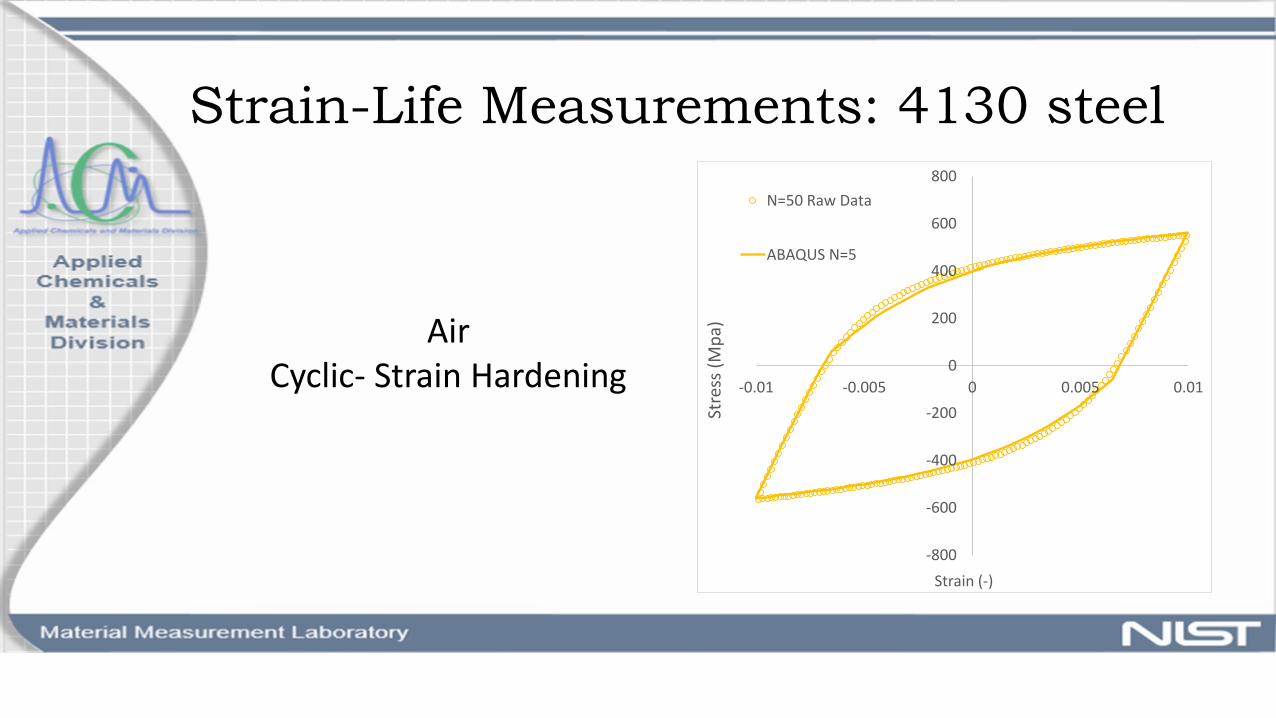
N=50 Raw Data
ABAQUS N=5
AirCyclic- Strain Hardening
Strain-Life Measurements: 4130 steel
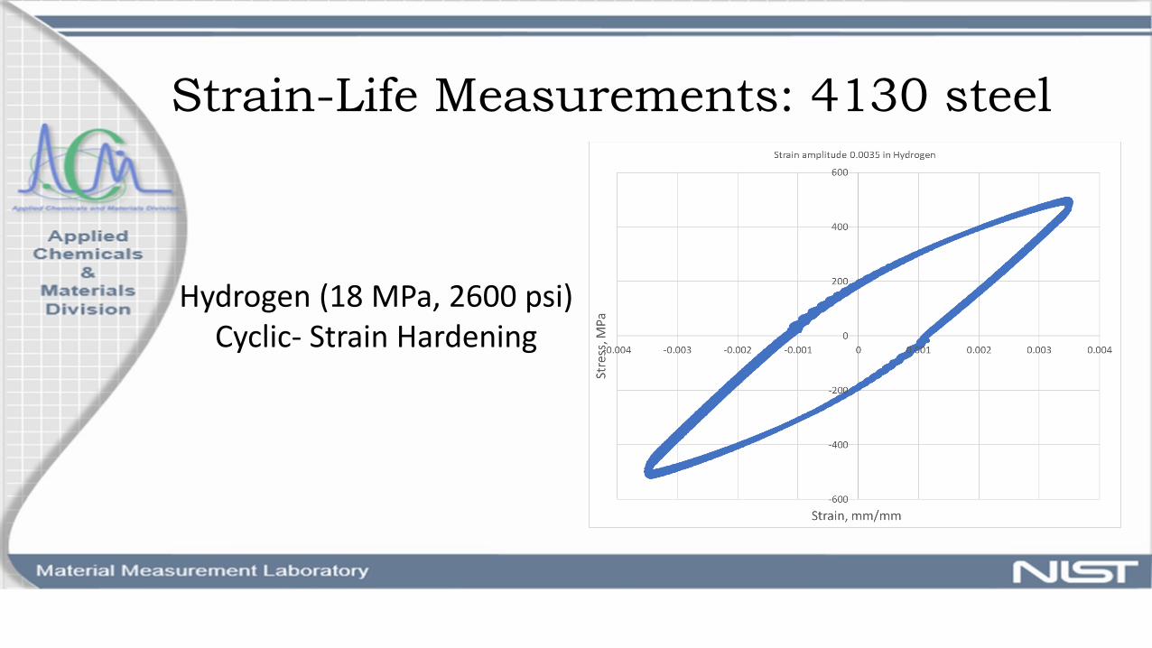
Hydrogen (18 MPa, 2600 psi)Cyclic- Strain Hardening

Strain-Life Measurements: 4130 steel
Hydrogen (18 MPa, 2600 psi)Fatigue

Modeling: Deformation Response for 4130 Steel at 2600 psi
• Chaboche cyclic plasticity model
• isotropic and kinematic hardening or softening• calibrated separately
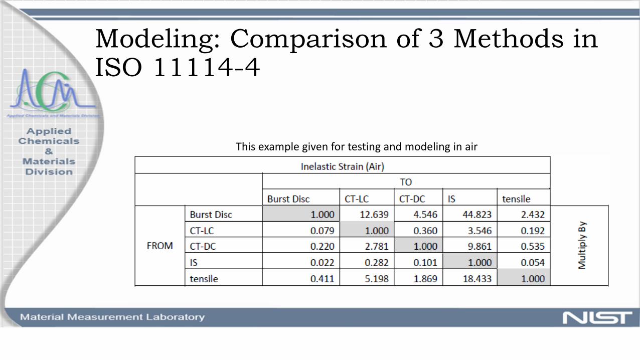
Modeling: Comparison of 3 Methods in ISO 11114-4
This example given for testing and modeling in air
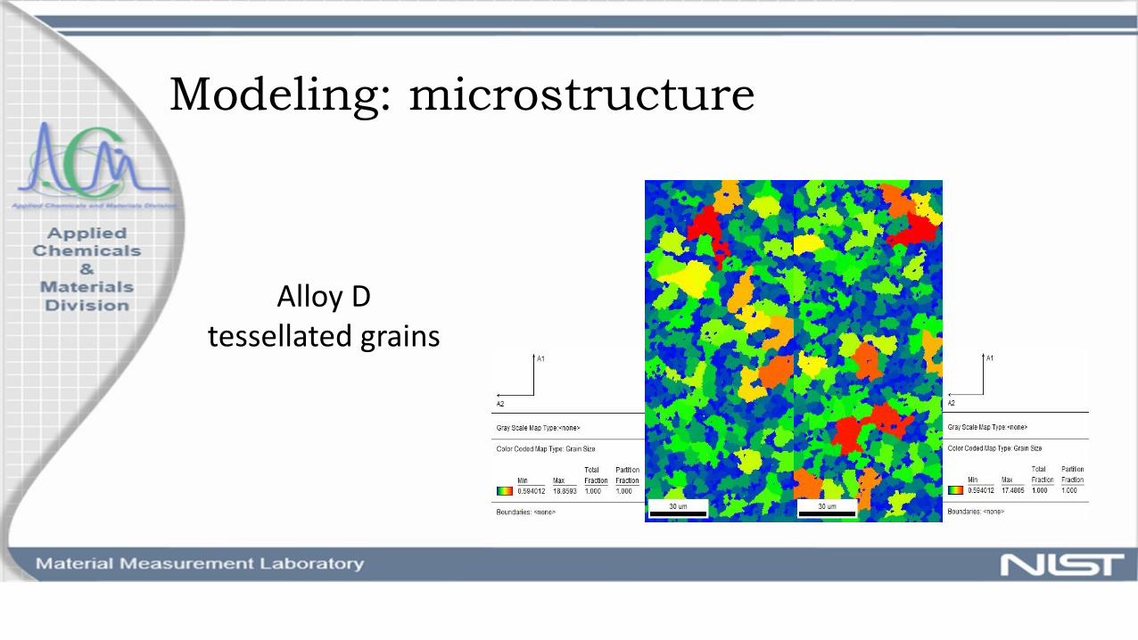
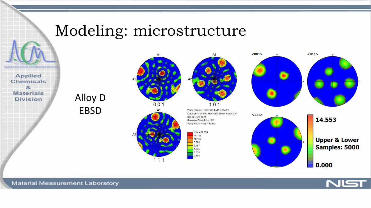
Modeling: microstructure
Alloy Dtessellated grains
Modeling: microstructure
Alloy DEBSD

Modeling: microstructure
Alloy Dsynthetic

18
Synthetic Alloy D in ABAQUS- Grain 9
BC: 2000 psi Hydrogen
Modeling: microstructure and Diffusivity
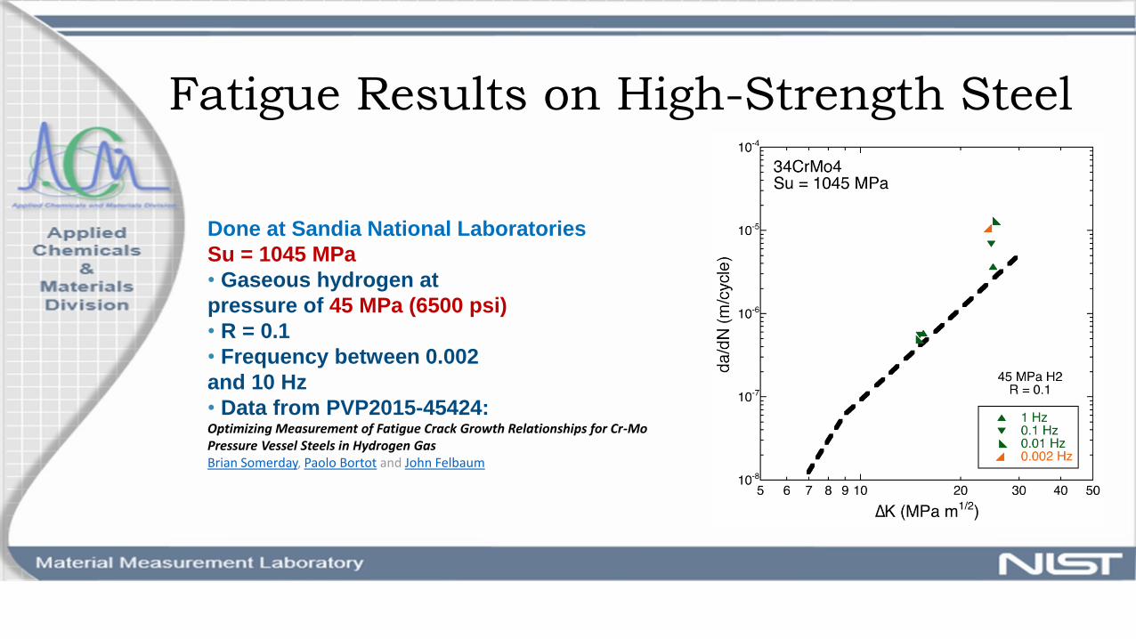
Fatigue Results on High-Strength Steel
Done at Sandia National Laboratories
Su = 1045 MPa
• Gaseous hydrogen at
pressure of 45 MPa (6500 psi)
• R = 0.1
• Frequency between 0.002
and 10 Hz
• Data from PVP2015-45424:Optimizing Measurement of Fatigue Crack Growth Relationships for Cr-Mo Pressure Vessel Steels in Hydrogen GasBrian Somerday, Paolo Bortot and John Felbaum
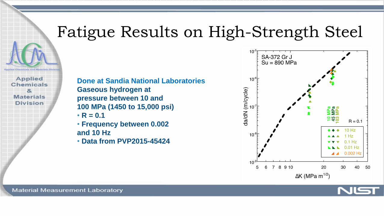
Fatigue Results on High-Strength Steel
Done at Sandia National Laboratories
Gaseous hydrogen at
pressure between 10 and
100 MPa (1450 to 15,000 psi)
• R = 0.1
• Frequency between 0.002
and 10 Hz
• Data from PVP2015-45424
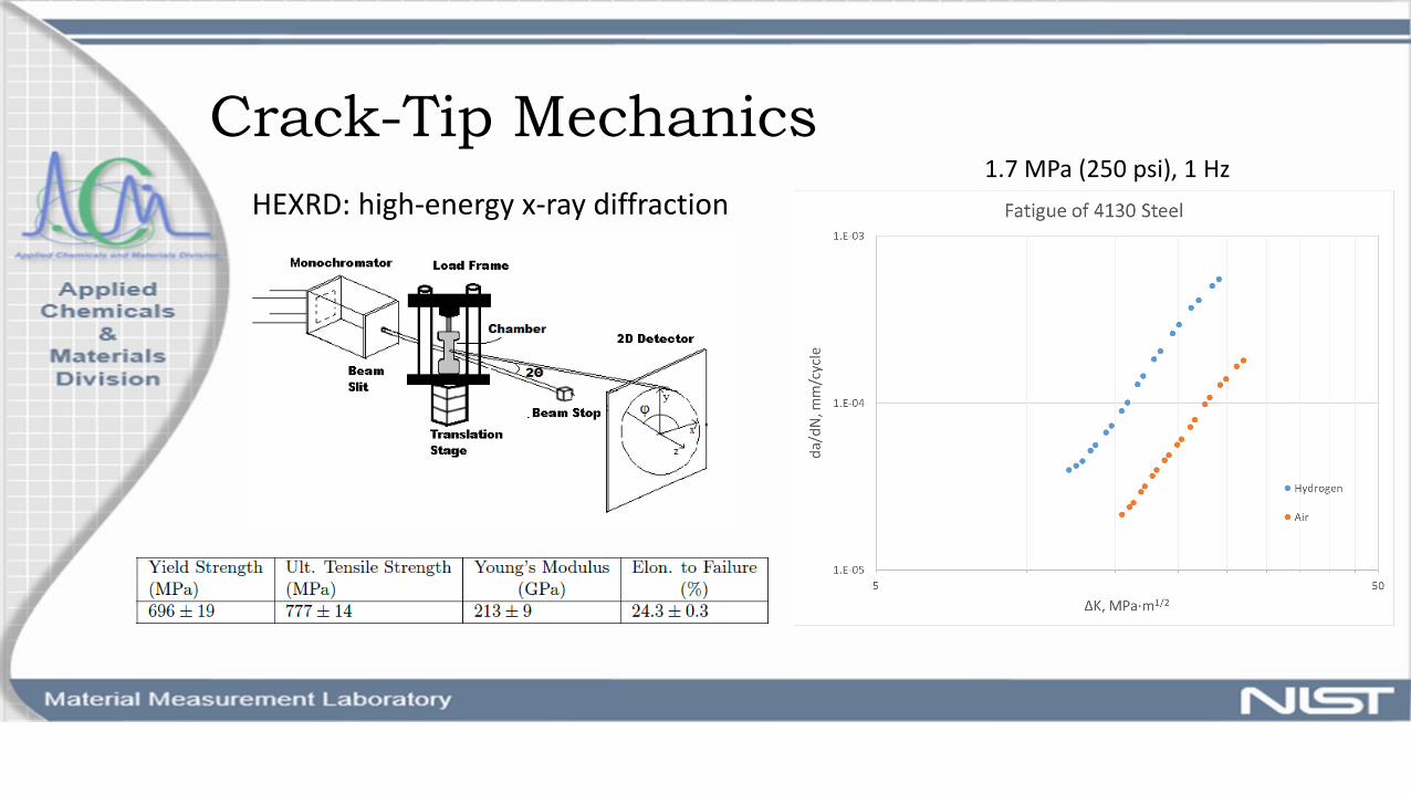
Crack-Tip Mechanics
HEXRD: high-energy x-ray diffraction1.7 MPa (250 psi), 1 Hz
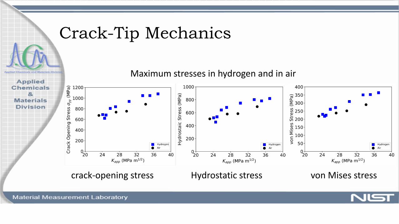
Crack-Tip Mechanics
Maximum stresses in hydrogen and in air
crack-opening stress Hydrostatic stress von Mises stress
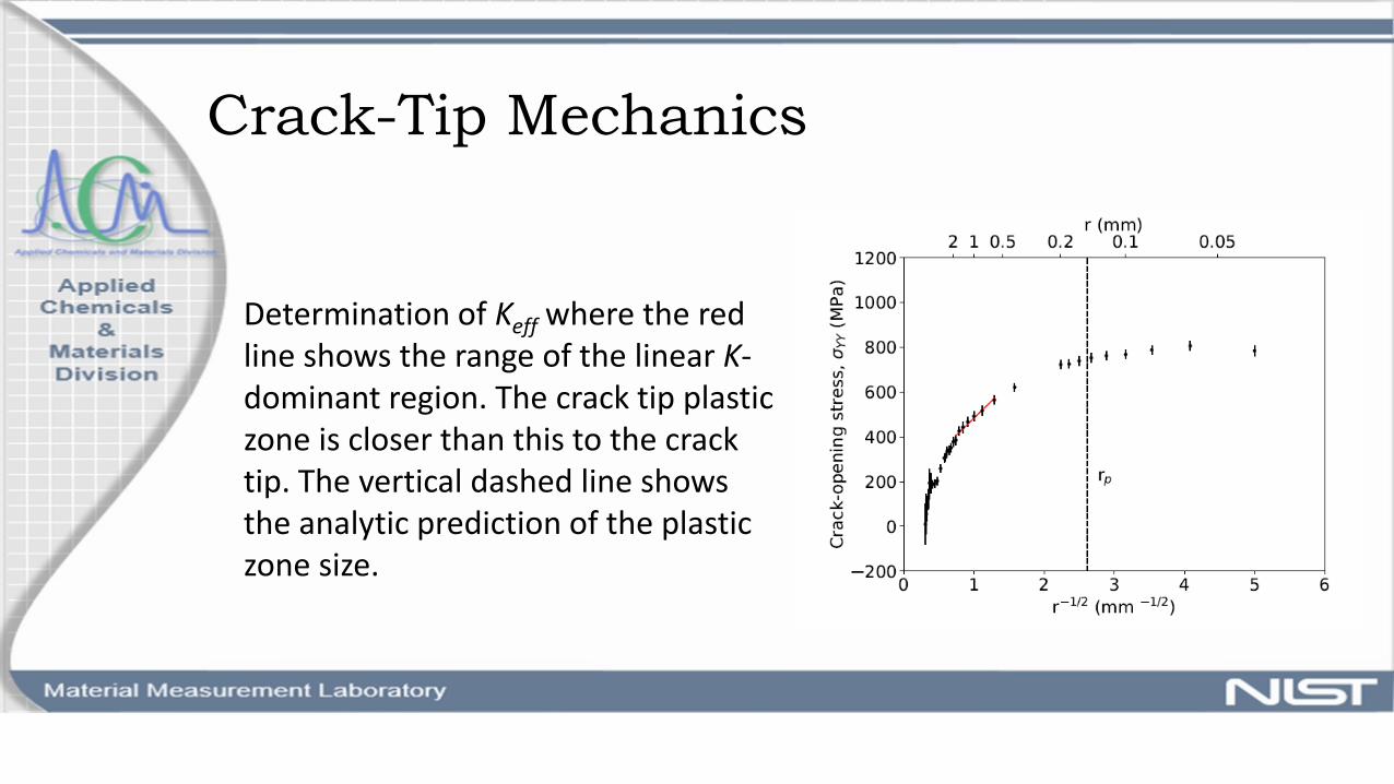
Crack-Tip Mechanics
Determination of Keff where the red line shows the range of the linear K-dominant region. The crack tip plastic zone is closer than this to the crack tip. The vertical dashed line shows the analytic prediction of the plastic zone size.

High-Strength Steel comparison
o New from Faber in Italyo UTS=1042 MPao Elongation to failure 17.4%
o Used for hydrogeno UTS=792 MPao Elongation to failure 24.2%

Next Steps
o Complete strain-life tests in hydrogeno Adjust model for hydrogen effectso Ask collaborators about definition of in-
service conditionso Begin tests on high-strength steelo Determine whether there is a pressure
effect?o Develop a model that will be used for
selecting steel intended for hydrogen pressure vessels

Fiber-Reinforced Polymer Materials for Cargo Tank Motor Vehicles
Emerging Packaging ResearchPHMSA Research and Development Forum
May 16-17, 2018
Mike CarolanMarisol Medri
Mark Raney (Program POC)Laura Sullivan
Hailing Yu (Project/Technical POC)Volpe National Transportation Systems Center
Cambridge, MA 02142
Acknowledgement of PHMSA Team
• Rick Boyle (Program POC)
• Victor Casillas (Project/Technical POC)
• Cheryl Freeman
• Satyaveda Bharath
• Eva Rodezno
27
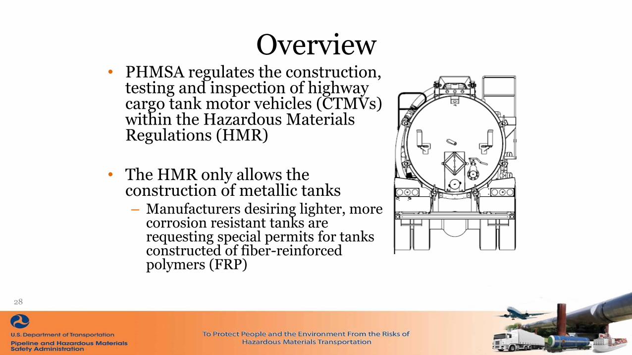
Overview• PHMSA regulates the construction,
testing and inspection of highway cargo tank motor vehicles (CTMVs) within the Hazardous Materials Regulations (HMR)
• The HMR only allows the construction of metallic tanks– Manufacturers desiring lighter, more
corrosion resistant tanks are requesting special permits for tanks constructed of fiber-reinforced polymers (FRP)
28
Problem Statement• FRP manufacturers must request special permits from
PHMSA because the HMR does not currently allow non-metallic CTMVs
• There are currently 6 manufacturers in the US and Canada constructing FRP CTMVs with special permits– Special permits are granted on an individual basis, and
may have varying conditions and restrictions
• Differing regulations in Canada and Europe already exist for CTMVs constructed of FRP
29
FRP Considerations• Key advantages
– Low density– High specific stiffness and specific strength – Good fatigue endurance– Excellent corrosion resistance– Outstanding thermal insulation– Low thermal expansion
• Areas of concern– Through-the-thickness mechanical properties– Impact damage tolerance– Fire performance
30
Challenges with FRP Construction
31
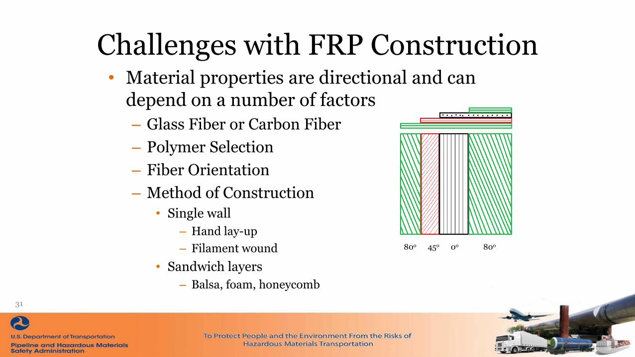
• Material properties are directional and can depend on a number of factors
– Glass Fiber or Carbon Fiber
– Polymer Selection
– Fiber Orientation
– Method of Construction
• Single wall
– Hand lay-up
– Filament wound
• Sandwich layers
– Balsa, foam, honeycomb
80o 45o 0o 80o
Project Objectives
• Establish experimental testing procedures and develop a finite element (FE) analysis framework for evaluating the performance and determining the specifications of FRP cargo tanks for highway HM transportation
• Provide performance data and technical parameters for PHMSA to develop uniform performance evaluation criteria and procedures for FRP CTMVs
32

Procurement of FRP Specimens – Task 1
• Review of manufacturers of FRP CTMVs currently operating under a special permit
– Discussion of manufacturing materials
– Discussion of type of manufacture
– Discussion of current characterization methods employed by the manufacturer
33
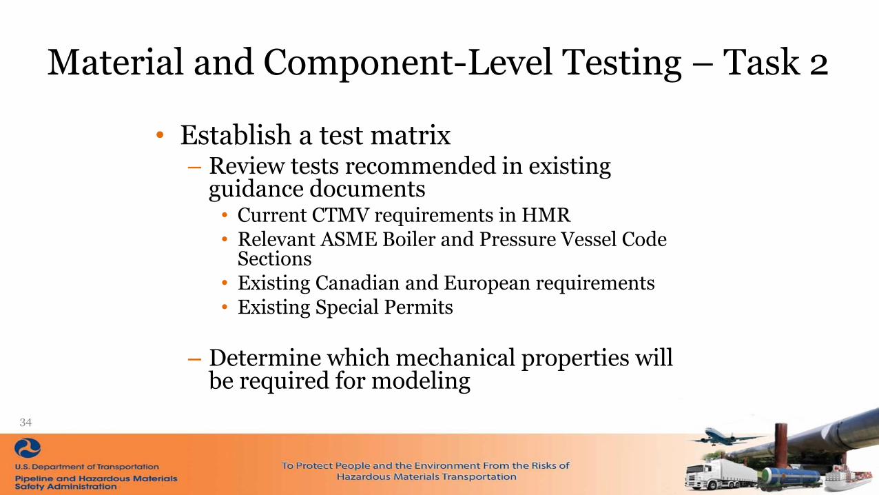
Material and Component-Level Testing – Task 2
• Establish a test matrix– Review tests recommended in existing
guidance documents• Current CTMV requirements in HMR• Relevant ASME Boiler and Pressure Vessel Code
Sections• Existing Canadian and European requirements• Existing Special Permits
– Determine which mechanical properties will be required for modeling
34

Material and Component Level Model Development – Task 3
• Develop FE models for each level of characterization– Static/dynamic anisotropic elasticity and strengths,
including impact strength and toughness– Fire resistance and/or thermomechanical properties– Performance under fatigue loading
35

Full Scale FRP Cargo Tank Model Development– Task 4
• Develop FE model of a representative CTMV– Make assumptions about accident damage protection
– Capacity and dimensions subject to constraints of weight and space that apply to existing trailers
36
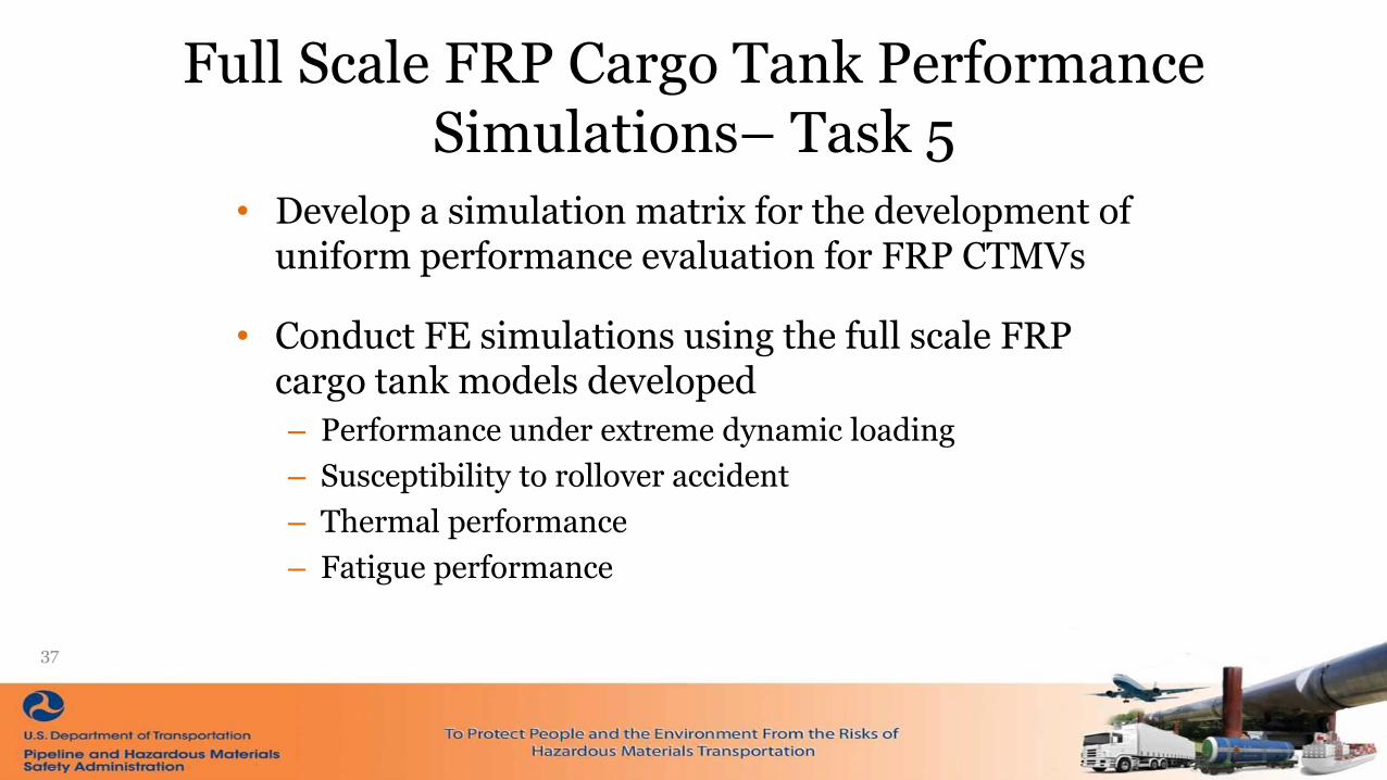
Full Scale FRP Cargo Tank Performance Simulations– Task 5
• Develop a simulation matrix for the development of uniform performance evaluation for FRP CTMVs
• Conduct FE simulations using the full scale FRP cargo tank models developed
– Performance under extreme dynamic loading
– Susceptibility to rollover accident
– Thermal performance
– Fatigue performance
37

Data Synthetization and Technical Parameter Development – Task 6
• Final report expected to include
– Material test reports for each level of material testing
– Review of existing FRP, CTMV, and FRP CTMV criteria and procedures
– Description of model development and verification/validation procedures
38
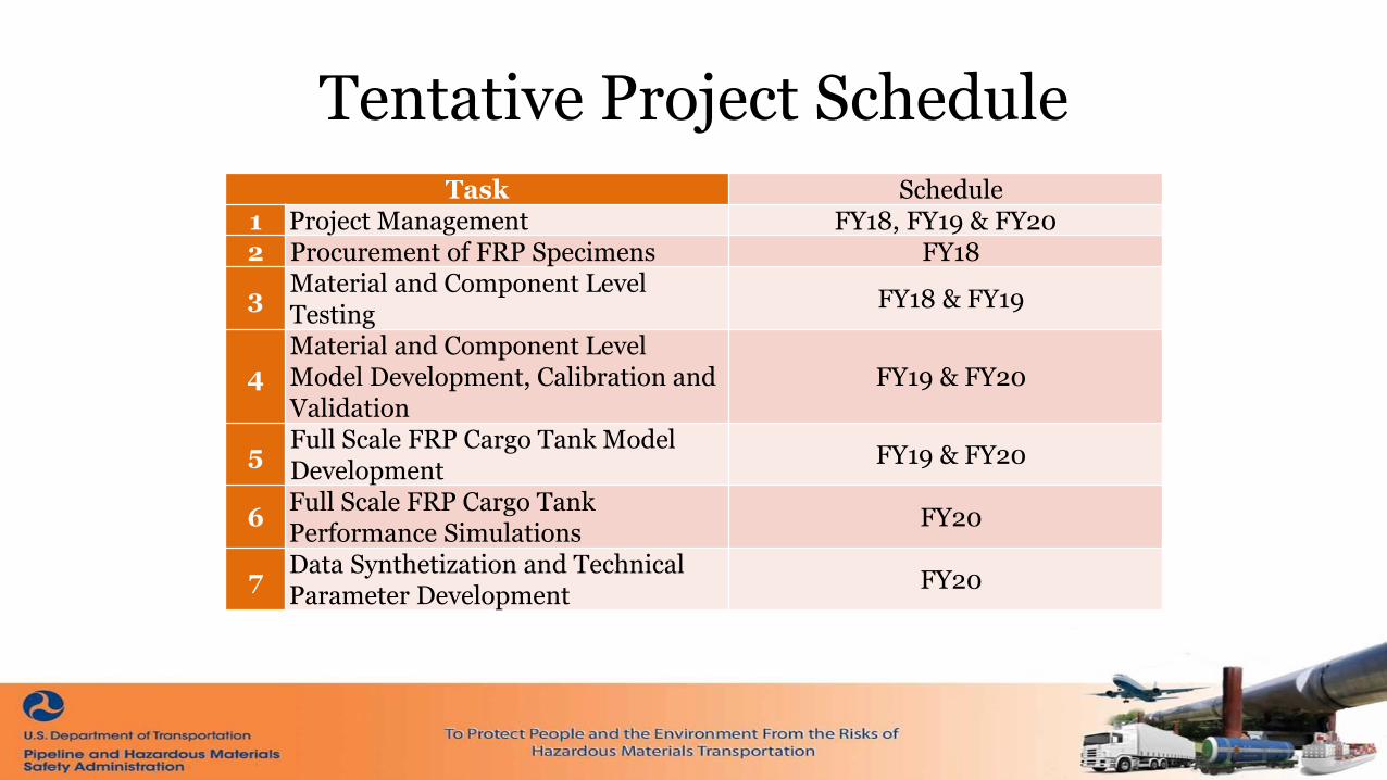
Tentative Project Schedule
Task Schedule1 Project Management FY18, FY19 & FY20 2 Procurement of FRP Specimens FY18
3Material and Component Level Testing
FY18 & FY19
4Material and Component Level Model Development, Calibration and Validation
FY19 & FY20
5Full Scale FRP Cargo Tank Model Development
FY19 & FY20
6Full Scale FRP Cargo Tank Performance Simulations
FY20
7Data Synthetization and Technical Parameter Development
FY20

Current Project Status
• Outreach to Manufacturers
– Method of manufacture
– Material properties for existing constructions
• Determine testing requirements
– From existing standards
– To provide sufficient data for model input and validation
40

Current Project Status• Samples being obtained
– Filament wound
– Hand lay-up
– Balsa
– Foam
– Honeycomb
• Test Matrix
– Strength and elasticity
– Impact
– Thermal properties
41

Questions?
42
Thank You!• For more information please visit us at
https://www.phmsa.dot.gov/research-and-development/hazmat/research-development-forum-may-16-17-2018

Shaped Charge Packaging Research
“Classification of
Conical Shaped Charges”
Southwest Research InstituteBallistics and Explosives Engineering
OHMS Research & Development Forum
NTSB Conference Center, Washington DC May 16-17, 2018
43
16 May 2018
Introduction
▪ Executing Agencies
DOT PHMSA (Funding Agency)
Southwest Research Institute (SwRI, Prime); Friedman Research Corporation (FRC, Subcontractor)
▪ Program Overview
Currently shaped charges are classified for transport either by UN Series 6 testing or through
analogy based on previously characterized designs.
The existing classification by analogy criteria is simply based on the net explosive weight (NEW) of
the device.
No scientific or engineering rational for this criteria has been documented.
SwRI and FRC are to conduct research leading to the development and validation of improved
criteria for shipping hazard classification of shaped charges by analogy.
It is intended that guidelines will be backed with experimental data to confirm their suitability and
limitations.
44
16 May 2018
Project Overview
▪ Shaped charges are used extensively in the commercial oil and gas industry.
▪ New designs must be reviewed for shipping/storage hazards.
Changes to the explosive fill, case, liner, or packaging requires a new analysis.
Packing multiple articles into a single package effects the final hazard classification.
Testing is required, at cost to Industry. No shipping can occur until EX# application is approved by
DOT.
▪ Can a suitable method for classification by default be developed to expedite this
process?
45
16 May 2018

What is a Shaped Charge?
46
16 May 2018
Jet Research Shaped Charge
▪ Shaped Charge Basics
Explosive billet is used to
collapse the liner, forming a
high-velocity jet.
The jet is used to perforate
geologic material in wells to
increase output.
Case material generates
radial fragmentation.

Jet Formation and Radial Fragmentation
47
16 May 2018
Typical Packaging
▪ ~10-50 articles per package
Intermediate packing and dividers; Paired charges in multiple rows
When multiple charges are packaged they must point inwards to
minimize the jetting effect in the event of an unintentional initiation
48
16 May 2018
Paired Charges

Hazard Classification Requirements
49
▪ Classification requirements as specified in
“Recommendation on the Transport of Dangerous Good, Model Regulations”
Volumes 1 and 2
• ST/SG/AC.10/1/Rev.19
▪ Testing as specified in
“Recommendation on the Transport of Dangerous Good, Manual of Tests and
Criteria”
• ST/SG/AC.10/11/Rev.5
Series 6 Tests
• A-D
16 May 2018
Explosive (Class 1) Divisions
50
▪ Division 1.1
Substances and articles which have a mass explosion hazard
• A mass explosion is one which affects almost the entire load virtually instantaneously
▪ Division 1.2
Substances and articles which have a projection hazard but not a mass explosion hazard.
▪ Division 1.3
Substances and articles which have a fire hazard and either a minor blast hazard or a minor projection hazard or both, but
not a mass explosion hazard.
▪ Division 1.4
Substances and articles which present no significant hazard
• This division comprises substances and articles which represent only a small hazard in the event of ignition or initiation during
transport. The effects are largely confined to the package and no projection of fragments of appreciable size or range is to be expected.
An external fire shall not cause virtually instantaneous explosion of almost the entire contents of the package.
16 May 2018
Shaped Charges typically fit into these categories

Classification
Flowchart
51
16 May 2018
▪ Normally conducted in alphabetical order.
Industry commonly skips straight to 6B.
6D not common.
• 1.4S no longer used for shaped charges.
Rudimentary instrumentation and data
requirements.
▪ Testing must be witness by an approved
Examiner.
EX application submitted to DOT for final
hazard classification.

6A – Single Package Test
52
▪ Test Purpose
To determine if there is a mass explosion of the contents.
• A charge is intentionally detonated in a package.
▪ Test Criteria
Evidence of a crater at the test site;
Damage to the witness plate beneath the package;
Measurement of blast;
Disruption and scattering of the confining material.
▪ Output
If mass explosion is detected, accept into Division 1.1, no further testing is needed.
Otherwise, proceed to test 6B
16 May 2018
6B – Stack Test
53
▪ Test Purpose
To determine whether an explosion is propagated from one package to another.
• A charge is intentionally detonated in group of packages.
▪ Test Criteria
A crater at the test site is appreciably larger than that given by a single package or unpackaged article;
Damage to the witness plate beneath the stack which is appreciably greater than that from a single
package or unpackaged article;
Measurement of blast which significantly exceeds that from a single package or unpackaged article;
Violent disruption and scattering of most of the confining material.
▪ Output
If mass explosion of more than one (1) packaged is detected, accept into Division 1.1, no further testing is
needed.
Otherwise, proceed to test 6C
16 May 2018
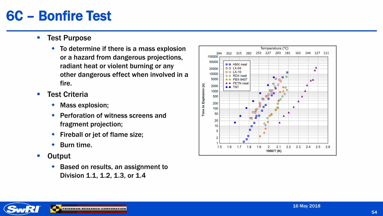
6C – Bonfire Test
54
▪ Test Purpose
To determine if there is a mass explosion
or a hazard from dangerous projections,
radiant heat or violent burning or any
other dangerous effect when involved in a
fire.
▪ Test Criteria
Mass explosion;
Perforation of witness screens and
fragment projection;
Fireball or jet of flame size;
Burn time.
▪ Output
Based on results, an assignment to
Division 1.1, 1.2, 1.3, or 1.4
16 May 2018
6D – Unconfined (Single) Package Test
55
▪ Test Purpose
To determine if there are hazardous effects outside the package.
▪ Test Criteria
Denting or perforation of the witness plate;
A flash or flame capable of igniting an adjacent material;
Disruption of the package causing projection of the explosives contents;
A projectile which passes completely through the packaging.
▪ Output
If there are hazardous effects outside the package, than the article is excluded from
Compatibility Group S.
16 May 2018

Development of Classification Criteria
56
▪ Purpose of criteria
To develop a science-based approach to classification by default
Expedite PHMSA’s application review process
Decreased industry testing costs
▪ Goals
Easily determined from basic materials, geometry and packaging
information
Consistent with historical Series 6 test results
Delineate between 1.1 and 1.4 Division assignments.
16 May 2018

Criteria Development
57
▪ Analyze historical Series 6 results.
▪ Review of historical DOE/DOD information on common explosive formulations
and their sensitivity.
▪ Examination insensitive munitions test results
Fast / slow cook-off and shock sensitivity
▪ Utilize analytical methods and simulations to estimate blast and fragment
environment during Series 6 testing.
Assess the sensitivity of explosive articles to these stimuli.
Conduct highly instrumented testing to fill data gaps where necessary.
▪ Compare metrics with historical Series 6 test results to show applicability.
Iterate as needed.
16 May 2018
Series 6 - Basic Responses
58
▪ Possible responses to Series 6 tests can be simplified into
one of three categories that determine the final Division
assignment.
Sympathetic Detonation
Cook-off (Fast or Slow)
No / Minimal Reaction
16 May 2018
Sympathetic Detonation
59
▪ Definition:
Initiation of an explosive article results in propagation of detonation
into adjacent articles or packages.
▪ Modes of propagation include:
Shaped charge jet impact
Case fragment impact
Blast over-pressure
16 May 2018

Sympathetic Detonation – Jet Impact
60
16 May 2018
Sympathetic Detonation – Radial Fragments
61
16 May 2018
Cook-off – Series 6C
62
▪ External heat (bonfire) causes fast or slow cook-off of an explosive article.
Fast cook-off can appear like a detonation.
Slow cook-off can cause projection of high speed/mass fragments due to internal pressurization of the shaped charge case.
▪ Response is a function of
Temperature and duration, rate of heat transfer, presence of venting in the explosive article, etc.
16 May 2018
Post-Test
Series 6C Bonfire Pre-Test
Questions ?
63
DonorReceptor
16 May 2018
Points of Contact
▪ PHMSA
Rick Boyle
• Chief of Research and Development
• U.S. Department of Transportation, Pipeline and Hazardous Materials Safety Administration
• Office of Hazardous Materials Safety Research & Development
▪ Southwest Research Institute
Scott Mullin
• Senior Program Manager
• (210) 522-2340
Carl Weiss (Principal Investigator)
• Manager – Ballistics and Explosives Engineering
• (210) 522-3996
64
16 May 2018
FRA - Office of Research, Development and Technology
Moving America Forward
F E D E R A L R A I L R O A D A D M I N I S T R A T I O NF E D E R A L R A I L R O A D A D M I N I S T R A T I O N
PHMSA R&D Forum
Melissa ShurlandFrancisco González, III
May 2018
FRA - Office of Research, Development and Technology
Moving America Forward
F E D E R A L R A I L R O A D A D M I N I S T R A T I O N
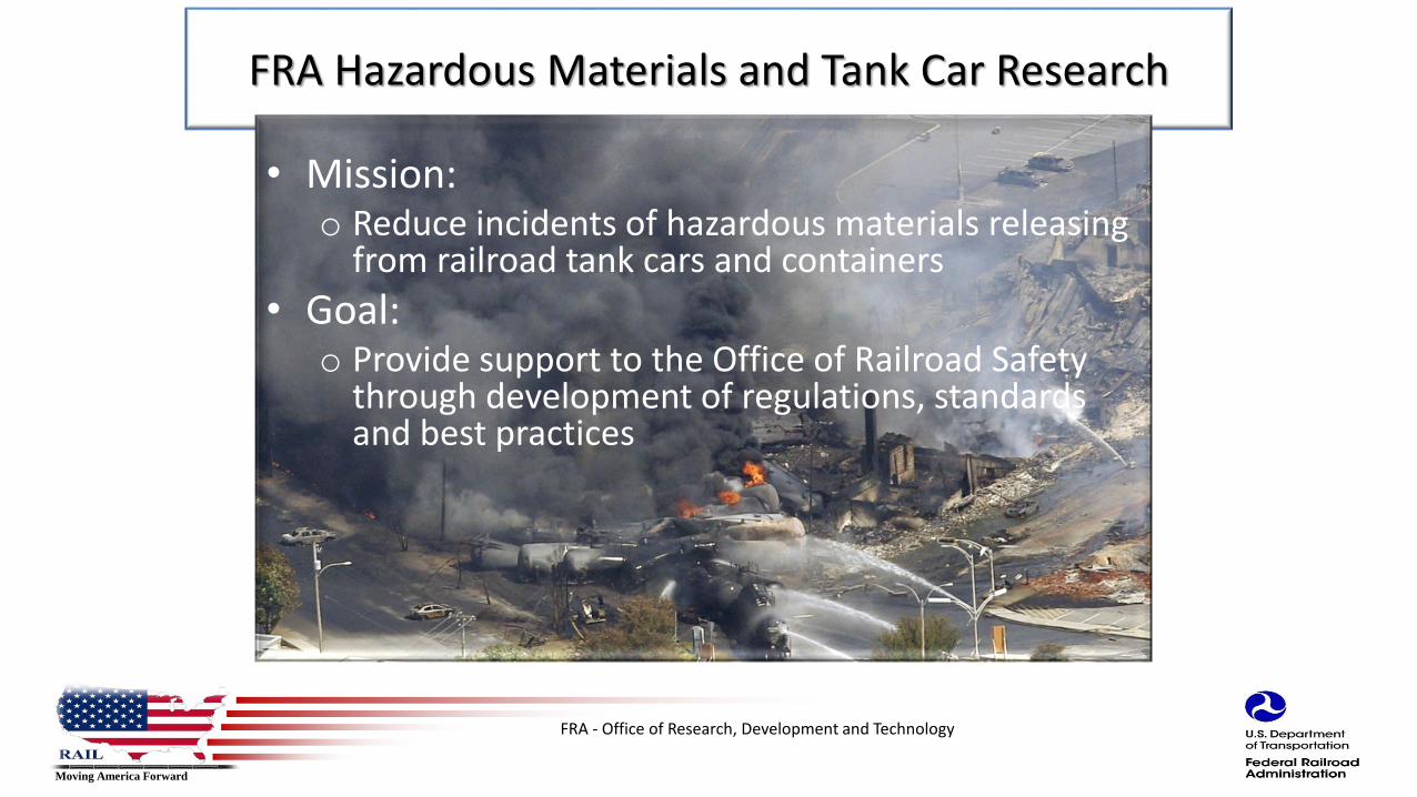
FRA Hazardous Materials and Tank Car Research
• Mission:o Reduce incidents of hazardous materials releasing
from railroad tank cars and containers
• Goal:o Provide support to the Office of Railroad Safety
through development of regulations, standards and best practices

FRA - Office of Research, Development and Technology
Moving America Forward
F E D E R A L R A I L R O A D A D M I N I S T R A T I O N
Fire test with an ISO tank on a Flat car
FRA - Office of Research, Development and Technology
Moving America Forward
F E D E R A L R A I L R O A D A D M I N I S T R A T I O N
Objectives
• Conduct a full scale fire test of a UN-T75 ISO tank used to transport LNG by rail.
• Provide a realistic fire exposure to the tank and the flatcar
• Obtain experimental data with internal and external instrumentation
• Assess the ability of a cryogenic portable tank to withstand exposure to a pool fire.
FRA - Office of Research, Development and Technology
Moving America Forward
F E D E R A L R A I L R O A D A D M I N I S T R A T I O N
Test data
• Test date: 11th May 2017, 1:15 PM at Southwest Research Institute (SwRI) facility
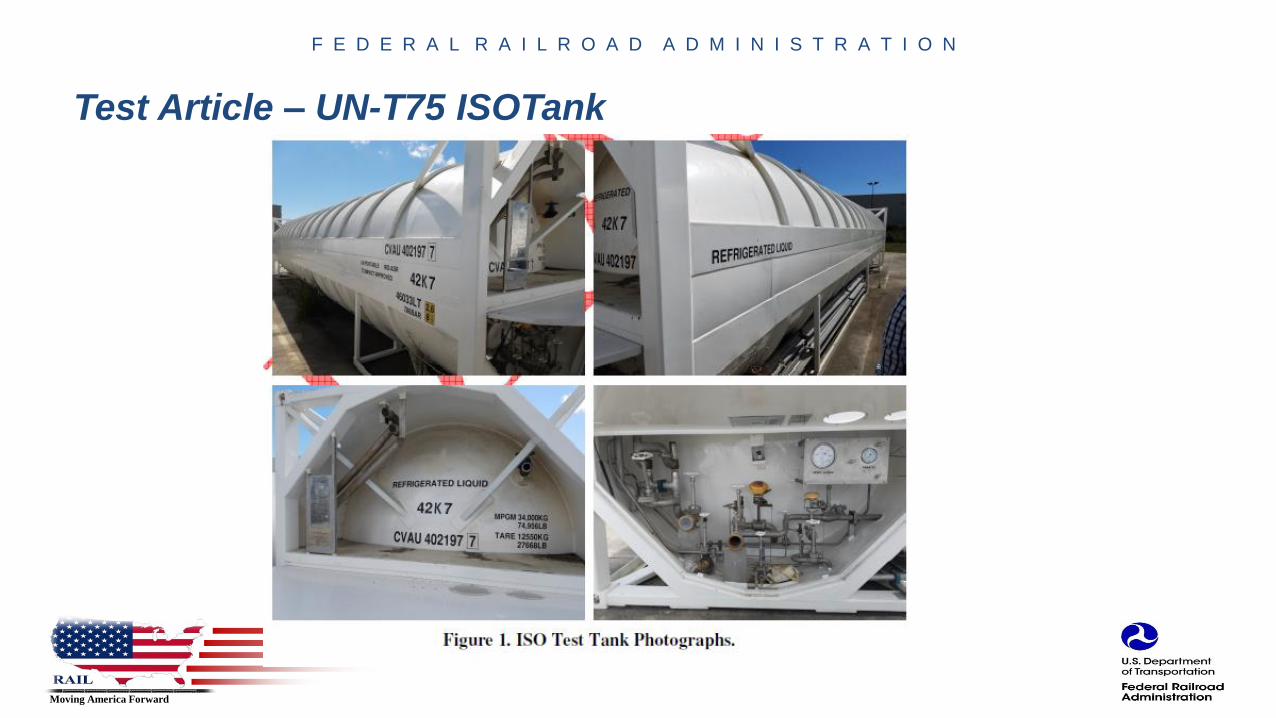
• UN-T75 ISO Portable tank: 10,000 gallon nominal capacity; 40 ft long and 9 ftdiameter located in the middle of a flat rail car (89 ft length)
• Tank was constructed by INOX/CVA with guidance from FRA and SwRI
• Tank was filled with liquid nitrogen
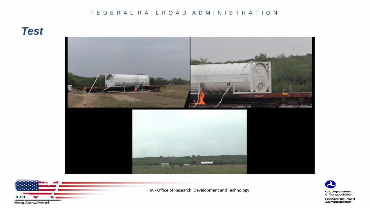
• Propane pool fire: 40 ft x 10 ft pool with pipe matrix to release propane liquid under 6” of water.– Propane: 7,000 gallons pumped from a storage tank about 800 ft from the test site.
FRA - Office of Research, Development and Technology
Moving America Forward
F E D E R A L R A I L R O A D A D M I N I S T R A T I O N
Test Article – UN-T75 ISOTank
FRA - Office of Research, Development and Technology
Moving America Forward
F E D E R A L R A I L R O A D A D M I N I S T R A T I O N
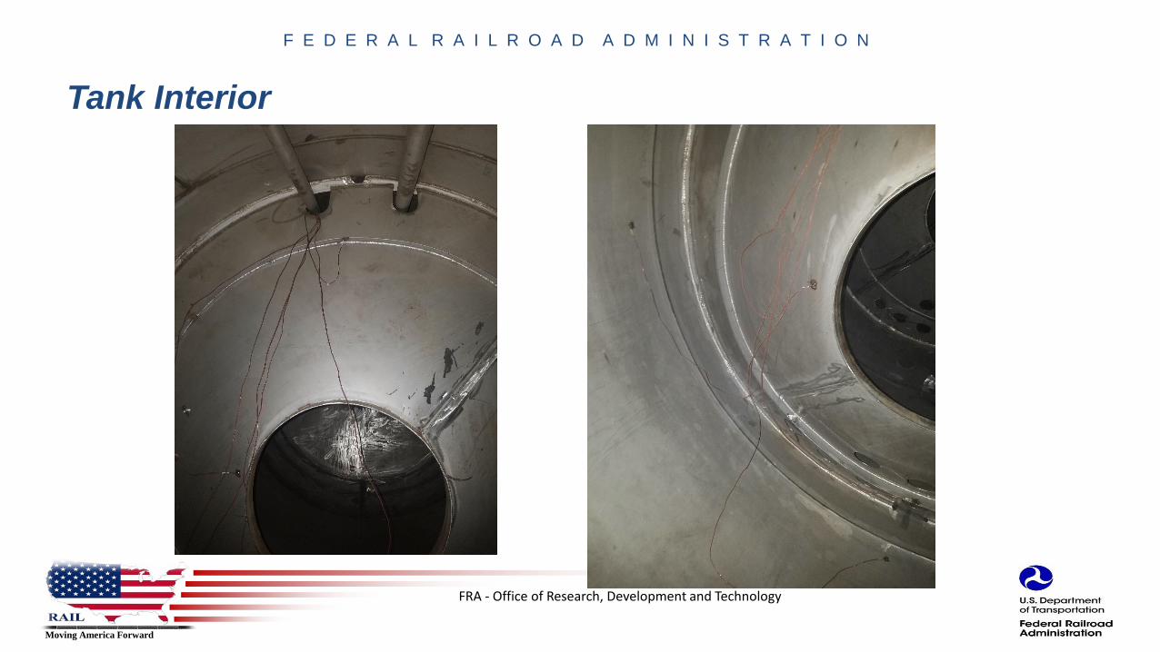
Tank Interior

FRA - Office of Research, Development and Technology
Moving America Forward
F E D E R A L R A I L R O A D A D M I N I S T R A T I O N
Test Setup

FRA - Office of Research, Development and Technology
Moving America Forward
F E D E R A L R A I L R O A D A D M I N I S T R A T I O N
Fire
FRA - Office of Research, Development and Technology
Moving America Forward
F E D E R A L R A I L R O A D A D M I N I S T R A T I O N
Test
FRA - Office of Research, Development and Technology
Moving America Forward
F E D E R A L R A I L R O A D A D M I N I S T R A T I O N
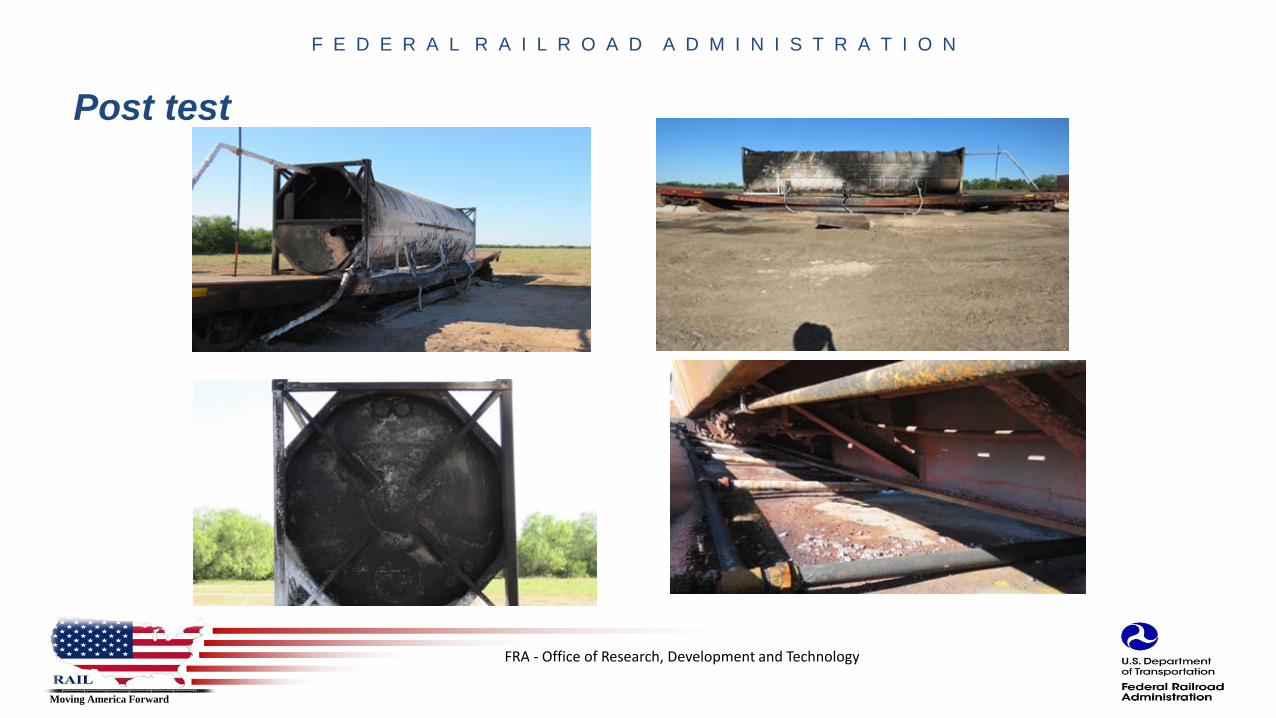
Post test

FRA - Office of Research, Development and Technology
Moving America Forward
F E D E R A L R A I L R O A D A D M I N I S T R A T I O N
Time Progression of Test Events
Time(h:min:s)
Observations
0:00:00 Start DAQ/Cameras
0:11:13 Lit torch
0:12:05 Liquid Propane Flow Initiated
0:12:16 Burner Ignited
0:14:58 Vacuum pressure increasing
0:21:00Tank Pressure and Vacuum pressure increasing, Flame pushed
to west side by wind
~0:24:00 Valve cover melting
0:33:45 Vacuum pressure signal lost
0:37:45 Vacuum pressure signal has returned, but may not be reliable
0:49:19 Some Type T TCs seem to be losing connection
0:56:23 All Type T TCs are unresponsive
FRA - Office of Research, Development and Technology
Moving America Forward
F E D E R A L R A I L R O A D A D M I N I S T R A T I O N
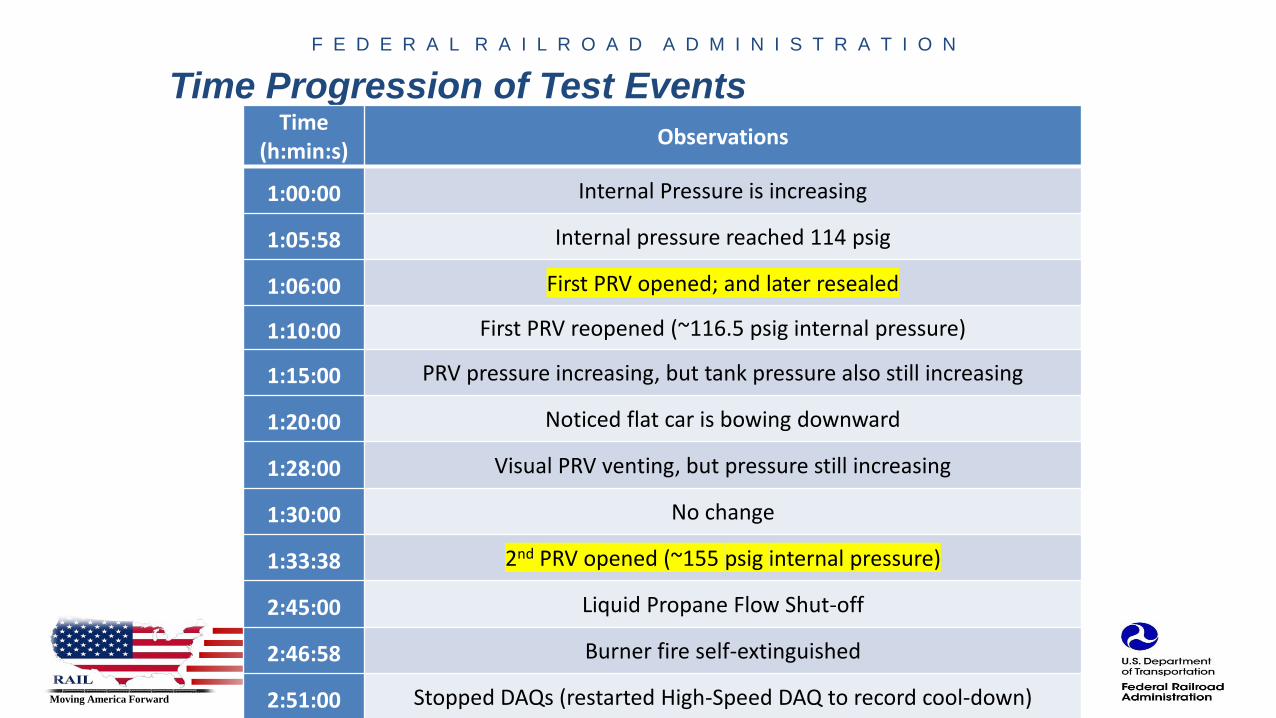
Time Progression of Test EventsTime
(h:min:s)Observations
1:00:00 Internal Pressure is increasing
1:05:58 Internal pressure reached 114 psig
1:06:00 First PRV opened; and later resealed
1:10:00 First PRV reopened (~116.5 psig internal pressure)
1:15:00 PRV pressure increasing, but tank pressure also still increasing
1:20:00 Noticed flat car is bowing downward
1:28:00 Visual PRV venting, but pressure still increasing
1:30:00 No change
1:33:38 2nd PRV opened (~155 psig internal pressure)
2:45:00 Liquid Propane Flow Shut-off
2:46:58 Burner fire self-extinguished
2:51:00 Stopped DAQs (restarted High-Speed DAQ to record cool-down)
FRA - Office of Research, Development and Technology
Moving America Forward
F E D E R A L R A I L R O A D A D M I N I S T R A T I O N
Post test Observations
• The tank successfully vented its contents, and did not rupture.
• The tank kept venting overnight and was at atmospheric pressure the next morning.
• When the flatcar started to buckle, it sank into the burner and impacted the piping, which contributed to burner performance.
• It was confirmed visibly that the fire damaged the vacuum pressure cable.
• The Type T thermocouple connections did not appear to sustain a lot of damage even though these channels stopped responding during the test.
– It may be possible that there was internal shorting out of these pass-through connectors, as opposed to the thermocouples.

FRA - Office of Research, Development and Technology
Moving America Forward
F E D E R A L R A I L R O A D A D M I N I S T R A T I O N
Test summary
• A UN-T75 ISO tank filled with LN2 was exposed to a liquid propane fire for 2 h, 35 min.
• There was no rupture or BLEVE of either the inner or outer tank.
• The fire temperature exceeded the yield temperature of steel in the flatcar. The flatcar buckled until it made contact with the fire pan.
• The pressure inside the inner tank increased monotonically during the fire exposure and stabilized at approximately 180 psig.
• The PRV system worked as designed. The lower pressure (116.5 psig) relief valve opened and reseated twice and then opened fully. The higher pressure valve opened at about 155 psig. The pressure continued to rise until 180 psi and the venting stabilized.
• There was additional venting after the fire was extinguished and venting continued for more than 3 h, 40 min

FRA - Office of Research, Development and Technology
Moving America Forward
F E D E R A L R A I L R O A D A D M I N I S T R A T I O N
2018-2019 Planned Research Activities
2018• Similar fire test of UN-T75 ISO Tank
• Use LNG in the tank
• Improvement in instrumentation and data recording
– Better Capture temperature of contents inside the tank
• Improvement in external data collection - video recording
2019
• Dynamic Impact test of LNG tender
• Follow AAR M-1004 Specification of Liquefied Natural Gas Fuel Tender
FRA - Office of Research, Development and Technology
Moving America Forward
F E D E R A L R A I L R O A D A D M I N I S T R A T I O N
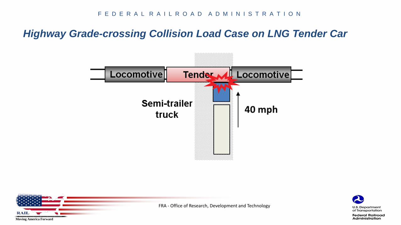
Highway Grade-crossing Collision Load Case on LNG Tender Car

FRA - Office of Research, Development and Technology
Moving America Forward
F E D E R A L R A I L R O A D A D M I N I S T R A T I O N
Test Objective
• Evaluate the survivability of valves and pipings enclosed in the side protective housing of a LNG tender car under impact of a 80,000 lb highway vehicle at 40 mph
• Side protective housing contains pipes and valves used to fuel and off-load LNG from tender.
• FRA is concerned that the valves may not operate as intended and shut close fully if the cabinet is impacted in a grade-crossing accident.
FRA - Office of Research, Development and Technology
Moving America Forward
F E D E R A L R A I L R O A D A D M I N I S T R A T I O N
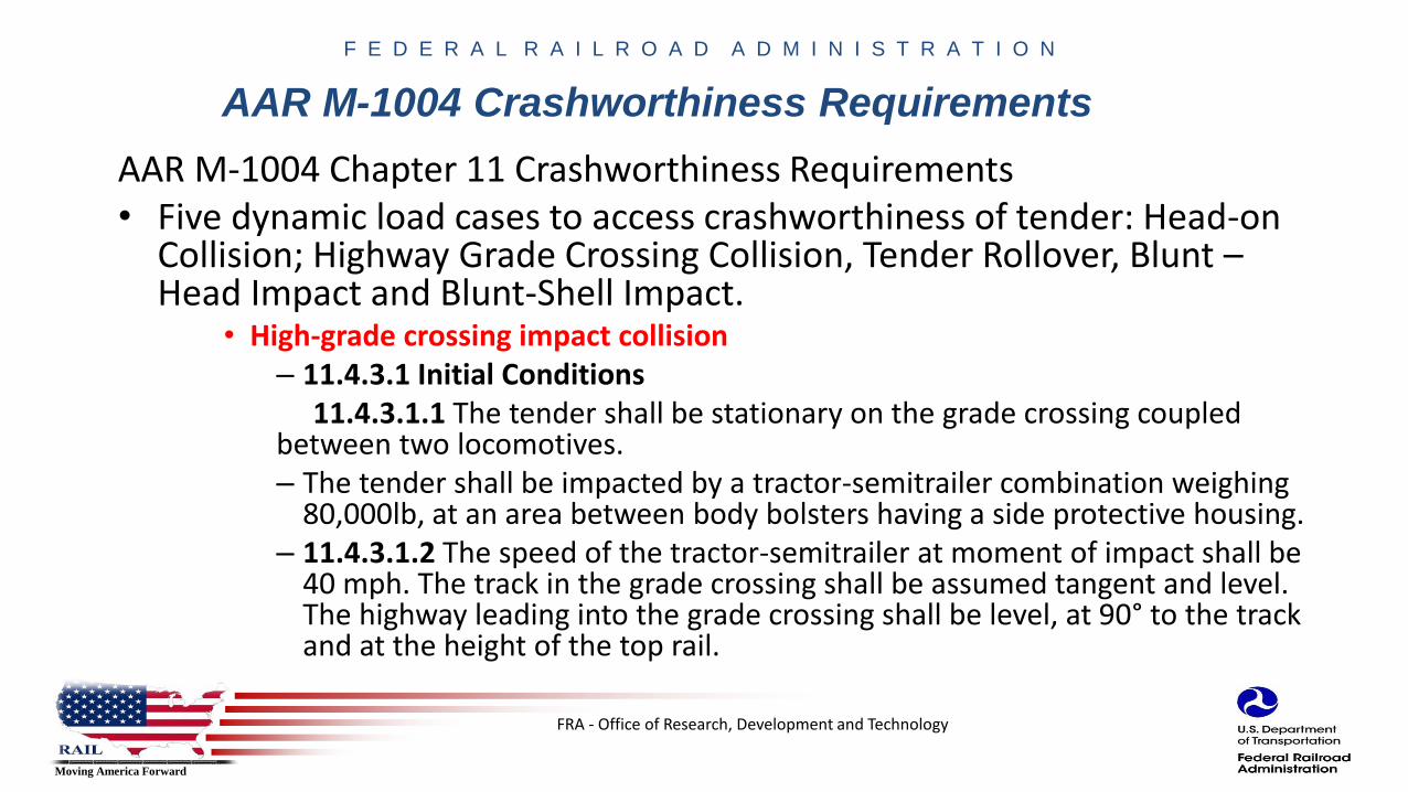
AAR M-1004 Crashworthiness Requirements
AAR M-1004 Chapter 11 Crashworthiness Requirements• Five dynamic load cases to access crashworthiness of tender: Head-on
Collision; Highway Grade Crossing Collision, Tender Rollover, Blunt –Head Impact and Blunt-Shell Impact.
• High-grade crossing impact collision– 11.4.3.1 Initial Conditions
11.4.3.1.1 The tender shall be stationary on the grade crossing coupled between two locomotives.– The tender shall be impacted by a tractor-semitrailer combination weighing
80,000lb, at an area between body bolsters having a side protective housing.– 11.4.3.1.2 The speed of the tractor-semitrailer at moment of impact shall be
40 mph. The track in the grade crossing shall be assumed tangent and level. The highway leading into the grade crossing shall be level, at 90° to the track and at the height of the top rail.

FRA - Office of Research, Development and Technology
Moving America Forward
F E D E R A L R A I L R O A D A D M I N I S T R A T I O N
Test Data
• LNG tender will be built to AAR M-1004 specifications– Will not include heat exchangers and internal cryogenic pump components
– INOX/CVA will build the tender
– Testing will be executed at Transportation Technology Center by Transportation Technology Center Inc.
– Finite Element Modeling will be done by The Volpe National Transportation Center
• Impact vehicle will be a 80,000 lb dump truck at 40 mph– AAR M-1004 specifies semi-tractor trailer. We will try to use a truck with similar chassis as the
semi-tractor trailer used in AAR modeling
– TTCI expressed concerns over controlling the trailer during the test and so relief from this requirement was sought and received from AAR
• LN2 will be filled in the tender
FRA - Office of Research, Development and Technology
Moving America Forward
F E D E R A L R A I L R O A D A D M I N I S T R A T I O NQuestions?
Francisco González , IIITank Car and Hazardous Materials Project Manager
Rolling Stock Research Division, FRA202-493-6076
Melissa ShurlandRail Energy, Efficiency and Environment Research
Rolling Stock Research Division, FRA202-493-1316

FRA - Office of Research, Development and Technology
Moving America Forward
F E D E R A L R A I L R O A D A D M I N I S T R A T I O NF E D E R A L R A I L R O A D A D M I N I S T R A T I O N
RAIL– Moving America Forward.
Visit us at:
www.fra.dot.gov