Download - HEAT EXCHANGER TECHNOLOGY
w w w.rhe em.co .nz
The versatile, high pressure hydraulic separator.
CASE STUDY
Pullman Hotel Adelaide, SA
Challenge
Pullman Hotel is Adelaide’s newest 5-star hotel
in the heart of the Central Business District
offering 308 rooms and suites.
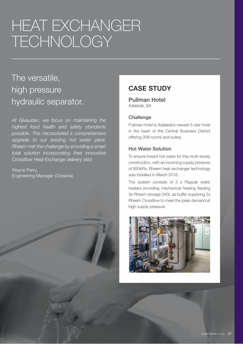
Hot Water Solution
To ensure instant hot water for this multi-storey
construction, with an incoming supply pressure
of 850kPa, Rheem heat exchanger technology
was installed in March 2018.
The system consists of 3 x Raypak water
heaters providing mechanical heating feeding
3x Rheem storage 340L as buffer supplying 2x
Rheem Crossflow to meet the peak demand at
high supply pressure.
At Givaudan, we focus on maintaining the highest food health and safety standards possible. This necessitated a comprehensive upgrade to our existing hot water plant. Rheem met the challenge by providing a smart total solution incorporating their innovative Crossflow Heat Exchange delivery skid.
Wayne Parry, Engineering Manager (Oceania)
HEAT EXCHANGER TECHNOLOGY
4747

48 w w w.rhe em.co .nz
Tankless, high pressure, instant hot water.
SUITED TO COMMERCIAL APPLICATIONS, PARTICULARLY MULTI-STOREY CONSTRUCTION
More power for the space
Variable speed pumps accurately match the required
energy load to deliver tankless, on-demand hot water with
exceptional temperature control.
Crossflow uses 25% of the space of an equivalent storage-
based system.
Low pressure loss
Crossflow exhibits exceptionally low pressure drop, so there’s
minimal impact on building design.
Built-in redundancy
Designed with dual-head pump and twin heat-exchangers
that share the load, allowing isolation for maintenance, with
no interruption to supply.
Highly efficient heat exchange
Can be used with all heating types, solar, heat pump, gas,
electric - as well as waste heat.
BMS and SCADA capability
Pump offers data transfer and monitoring capabilities to BMS
or SCADA systems by an add-on CIM module suitable for
Modbus, Bacnet and Lonworks.
More key features
• Factory assembled and tested on a hot dip galvanized frame
• All fittings and pipe work are 316L stainless steel
• Can be used as a hydraulic separator for solar, Co-gen and
PP-R systems
• Grundfos Go remote APP Bluetooth enabled
MODEL DIM 'H1' DIM 'H2'
RD200D701 877 1522
RD400D701 930 1575
RD600D701 993 1638
RD800D701 1056 1701
CHILLINGLOAD
80 YEARS LOCALMANUFACTURINGCERTIFIED CONNECTIVITY
REDUCEDHIGH PRESSUREkPa1400ELECTRIC SOLARHEAT PUMP
WATER SAVING BOILING/CHILLED
BMS SMALLW2W HEATTRANSFER
CHILLING LOADCOMPACT
CERTIFIEDREDUCED
EFFICIENCY*7.0UP
TO COPHEAT PUMP
Rooftop penthouse vs. rooftop plant
High working pressure of 1400kPa, the result of its hydraulic separator design, means
Crossflow™ can be located in the basement of tall buildings - leaving rooftop space
available for more profitable allocation.
RHEEM CROSSFLOWTM
Rheem CrossFlowTM warranty: 1 year on heat exchanger, 1 year on parts & labour

49w w w.rhe em.co .nz
* The maximum working pressure of each side of the system will be governed by the lowest operating appliance connected to it. The potable side (secondary side) water pressure must be higher than the non potable side (primary side) pressure.
CROSS FLOW DIMENSIONS AND TECHNICAL DATA TABLE - RHEEM CROSSFLOW
Model RD200 RD400 RD600 RD800
Nominal Capacity kW 200 400 600 800
Parameters for Nominal Capacity Rating
Primary Side (non-potable)
Inlet Temp oC 80 80 80 80
Flow Rate L/min 48 114 144 186
Pressure Drop kPa 24 47 36 36
Secondary Side (potable)
Inlet/Outlet Temp oC 15/65 15/65 15/65 15/65
Flow Rate L/min 57 115 172 223
Pressure Drop kPa 37 47 51 48
Dimensions H x W x D mm 1364 x 761 x 700
Weight kg 130 138 147 156
Pipe Connections Primary Circuit BSPF RP1¼
Pipe Connections Secondary Circuit 50mm Flange Type E
Max Operating Pressure Primary Circuit kPa 1400*Max Operating Pressure Secondary Circuit kPa 1400*Electrical Supply 230-240V 50/60Hz Hard Wired By Electrician
Min Circuit Size Amps 10
0
10
20
30
40
50
60
0 0.5 1 1.5 2 2.5 3 3.5 4
Pre
ssur
e D
rop
KP
a
Flow rate L/s
Rheem CrossflowSecondary Side Pressure Drop vs Flow Rate
200kW 400kW 600kW 800kW200kW 400kW 600kW 800kW
0
100
200
300
400
500
600
700
800
900
65 67 69 71 73 75 77 79 81 83 85
Out
put
(kW
)
Rheem Crossflow Maximum Output (Tin15⁰C-Tout65⁰C) vs Primary supply temp
Primary supply temp (⁰C)
200kW 400kWPrimary Temp 90 85 80 75 70 65 Primary Temp 90 85 80 75 70 65Output (kW) 270 215 200 190 160 100 Output (kW) 500 450 400 365 300 200Temp Rise Secondary Side Flow Rate (L/min) Temp Rise Secondary Side Flow Rate (L/min)65 60 47 44 42 35 65 110 99 88 80 6660 65 51 48 45 38 24 60 119 108 96 87 72 4855 70 56 52 50 42 26 55 130 117 104 95 78 5250 77 62 57 54 46 29 50 143 129 115 105 86 5745 86 68 64 61 51 32 45 159 143 127 116 96 6440 97 77 72 68 57 36 40 179 161 143 131 108 7235 111 88 82 78 66 41 35 205 184 164 149 123 82
600kW 800kWPrimary Temp 90 85 80 75 70 65 Primary Temp 90 85 80 75 70 65Output (kW) 740 680 600 535 450 300 Output (kW) 940 870 800 695 580 400Temp Rise Secondary Side Flow Rate (L/min) Temp Rise Secondary Side Flow Rate (L/min)65 163 150 132 118 99 65 207 192 176 153 12860 177 162 143 128 108 72 60 225 208 191 166 139 9655 193 177 156 139 117 78 55 245 227 208 181 151 10450 212 195 172 153 129 86 50 269 249 229 199 166 11545 236 217 191 170 143 96 45 299 277 255 221 185 12740 265 244 215 192 161 108 40 337 312 287 249 208 14335 303 278 246 219 184 123 35 385 356 328 285 238 164
2 x 600kW 2 x 800kWPrimary Temp 90 85 80 75 70 65 Primary Temp 90 85 80 75 70 65Output (kW) 1480 1360 1200 1070 900 600 Output (kW) 1880 1740 1600 1390 1160 800Temp Rise Secondary Side Flow Rate (L/min) Temp Rise Secondary Side Flow Rate (L/min)65 326 300 265 236 198 65 415 384 353 307 25660 354 325 287 256 215 143 60 449 416 382 332 277 19155 386 354 313 279 235 156 55 490 453 417 362 302 20850 424 390 344 307 258 172 50 539 499 459 398 333 22945 471 433 382 341 287 191 45 599 554 510 443 369 25540 530 487 430 383 323 215 40 674 624 573 498 416 28735 606 557 491 438 369 246 35 770 713 655 569 475 328
Cross Flow Delivery Skid Secondary Side Flow Rate for Varying Primary Supply Temperatures and Secondary Side Temperature Rise
Rheem Crossflow Maximum Output (Tin15oC-Tin65oC) vs. Primary supply temp
Rheem Crossflow Secondary Side Pressure Drop vs. Flow Rate
0
10
20
30
40
50
60
0 0.5 1 1.5 2 2.5 3 3.5 4
Pre
ssur
e D
rop
KP
a
Flow rate L/s
Rheem CrossflowSecondary Side Pressure Drop vs Flow Rate
200kW 400kW 600kW 800kW200kW 400kW 600kW 800kW
0
100
200
300
400
500
600
700
800
900
65 67 69 71 73 75 77 79 81 83 85
Out
put
(kW
)
Rheem Crossflow Maximum Output (Tin15⁰C-Tout65⁰C) vs Primary supply temp
Primary supply temp (⁰C)
TECHNICAL DATA
CHILLINGLOAD
80 YEARS LOCALMANUFACTURINGCERTIFIED CONNECTIVITY
REDUCEDHIGH PRESSUREkPa1400ELECTRIC SOLARHEAT PUMP
WATER SAVING BOILING/CHILLED
BMS SMALLW2W HEATTRANSFER
CHILLING LOADCOMPACT
CERTIFIEDREDUCED
EFFICIENCY*7.0UP
TO COPHEAT PUMP
CHILLINGLOAD
80 YEARS LOCALMANUFACTURING CERTIFIED
REDUCEDELECTRIC SOLARHEAT PUMP
WATER SAVING BOILING/CHILLED
CERTIFIEDSTEELSTAINLESS316 MINIMUM
PRESSUREDROPEASY TO
MAINTAIN
CERTIFIED CONNECTIVITYHIGH PRESSURE
kPa1400 BMS SMALL
W2W HEATTRANSFER
50 w w w.rhe em.co .nz
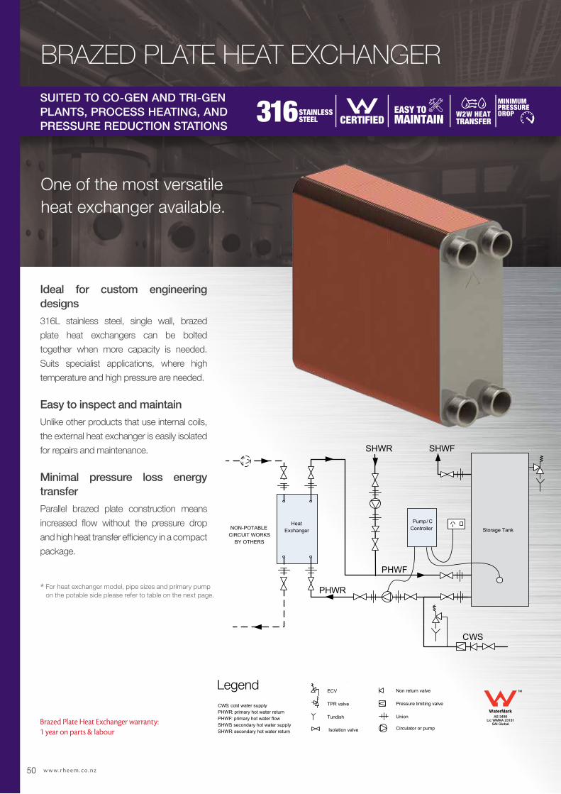
One of the most versatile heat exchanger available.
SUITED TO CO-GEN AND TRI-GEN PLANTS, PROCESS HEATING, AND PRESSURE REDUCTION STATIONS
Storage Tank
SHWFSHWR
NON-POTABLE CIRCUIT WORKS
BY OTHERS
HeatExchanger
Pump/ C Controller
CWS
PHWF
PHWR
LEGENDCWS: cold water supplyPHWR: primary hot water returnPHWF: primary hot water flowSHWS: secondary hot water supplySHWR: secondary hot water return
ECV
TPR valve
Tundish
Isolation valve
Non return valve
Pressure limiting valve
Union
Circulator or pump
Ideal for custom engineering designs
316L stainless steel, single wall, brazed
plate heat exchangers can be bolted
together when more capacity is needed.
Suits specialist applications, where high
temperature and high pressure are needed.
Easy to inspect and maintain
Unlike other products that use internal coils,
the external heat exchanger is easily isolated
for repairs and maintenance.
Minimal pressure loss energy transfer
Parallel brazed plate construction means
increased flow without the pressure drop
and high heat transfer efficiency in a compact
package.
* For heat exchanger model, pipe sizes and primary pump on the potable side please refer to table on the next page.
AS 3498Lic WMKA 23131
SAI Global
TM
Storage Tank
SHWFSHWR
NON-POTABLE CIRCUIT WORKS
BY OTHERS
HeatExchanger
Pump/ C Controller
CWS
PHWF
PHWR
LEGENDCWS: cold water supplyPHWR: primary hot water returnPHWF: primary hot water flowSHWS: secondary hot water supplySHWR: secondary hot water return
ECV
TPR valve
Tundish
Isolation valve
Non return valve
Pressure limiting valve
Union
Circulator or pump
Legend
BRAZED PLATE HEAT EXCHANGER
Brazed Plate Heat Exchanger warranty: 1 year on parts & labour

CHILLINGLOAD
80 YEARS LOCALMANUFACTURING CERTIFIED
REDUCEDELECTRIC SOLARHEAT PUMP
WATER SAVING BOILING/CHILLED
CERTIFIEDSTEELSTAINLESS316 MINIMUM
PRESSUREDROPEASY TO
MAINTAIN
CERTIFIED CONNECTIVITYHIGH PRESSURE
kPa1400 BMS SMALL
W2W HEATTRANSFER
51w w w.rhe em.co .nz
POTABLE SIDE PUMP AND PIPE SIZING
Heat Exchanger
Model
Qty In Parallel
Output (kW)
Design Flow Rate
Minimum Potable
Primary F & R Pipe Size
(mm)
Pump Model / Speed Setting
0191750 1 50 0.61 32 UPS20-60N / 3
0191750 2 100 1.22 40 UPS32-80N / 3
0191751 1 100 1.21 40 UPS32-80N / 3
0191751 2 200 2.42 50 UPS40-60/2FB / 2
0191752 1 150 1.82 50 UPS32-80N / 3
0191752 2 300 3.64 65 UPS40-60/2FB / 3
0191753 1 200 2.43 50 UPS40-60/2FB / 3
0191753 2 400 4.86 80 UPS50-120FB / 1
0191754 1 250 3.03 65 UPS40-60/2FB / 3
0191754 2 500 6.06 80 UPS50-120FB / 3
NOTE: Pipe sizing, pump selection and installation of the NON-POTABLE circuit is not covered by Rheem. Pipe and pump sizing is for potable water side only between the heat exchanger and storage tank/s and is based on 25m TOTAL pipe run and 20 x 90° bends @1.2m/s. If the piping is beyond this scope, please contact Rheem for assistance.
* The maximum working pressure of each side of the system will be governed by the lowest operating appliance connected to it. The potable side (secondary side) water pressure must be higher than the non potable side (primary side) pressure.
HEAT EXCHANGER DIMENSIONS AND TECHNICAL DATA TABLE - RHEEM HEAT EXCHANGER
Part Number 0191750 0191751 0191752 0191753 0191754
Nominal Rating kW 50 100 150 200 250
Par
amet
ers
for
Nom
inal
Rat
ing
Non Potable Side Inlet/Outlet Temp oC 80/60 80/60 80/60 80/60 80/60
Flow Rate L/sec 0.61 1.22 1.83 2.44 3.05
Pressure Drop kPa 2.65 3.74 5.00 6.98 9.83
Potable Side Inlet/Outlet Temp oC 45/65 45/65 45/65 45/65 45/65
Flow Rate L/sec 0.61 1.21 1.82 2.43 3.03
Pressure Drop kPa 2.39 3.59 4.91 6.91 9.79
Dimensions Depth (D) mm 104 160 221 277 333
Weight kg 6 9 12 15 18
Operating Pressure kPa 3000*
Electrical Supply (Temperature Controller) 230-240V 50/60Hz Hard Wired By Electrician
11763
D
27
287
234
G11/4
G11/4
TECHNICAL DATA


