Download - Graphene-based Soft Wearable Antennas
Graphene-based Soft
Wearable Antennas
1‡Isidoro Ibanez-Labiano, 2M. Said Ergoktas, 2Coskun Kocabas, 3Anne Toomey, 1Akram Alomainy,
3*Elif Ozden-Yenigun
1School of Electronic Engineering and Computer Science, Queen Mary University of London, United Kingdom
2Department of Material and National Graphene Institute, University of Manchester, United Kingdom
3School of Design, Textiles, Royal College of Art, London, United Kingdom
Abstract Electronic textiles (e-textiles) are about to face tremendous environmental and resource challenges due
to the complexity of sorting, the risk to supplies and metal contamination in textile recycling streams.
This is because e-textiles are heavily based on the integration of valuable metals, including gold, silver
and copper. In the context of exploring sustainable materials in e-textiles, we tested the boundaries of
chemical vapour deposition (CVD) grown multi-layer (ML) graphene in wearable communication
applications, in which metal assemblies are leading the way in wearable communication. This study
attempts to create a soft, textile-based communication interface that does not disrupt tactile comfort and
conformity by introducing ML graphene sheets. The antenna design proposed is based on a
multidisciplinary approach that merges electromagnetic engineering and material science and integrates
graphene, a long-lasting alternative to metal components. The designed antenna covers a wide
bandwidth ranging from 3 GHz to 9 GHz, which is a promising solution for a high data rate and efficient
communication link. We also described the effects of bending and proximity to the human body on the
antenna’s overall performance. Overall, the results suggested that graphene-based soft antennas are a
viable solution for a fully integrated textile-based communication interface that can replace the current
rigid, restrictive and toxic approaches, leading to a future where eco-friendliness and sustainability is
the only way forward!
Keywords – Graphene; wearable antenna; ultra-wideband communication; chemical vapour
deposition; e-textiles.
1. Introduction Smart textiles have become an active research field in recent decades, with increasing interest in
wearable and flexible platforms for the integration of various functionalities, from sensor-based devices
to user-interface elements. Textiles that provide a seamless command-oriented user interface [1] and
that are capable of wireless communication [2-3] have been an increasingly popular research topic in
recent years. The notion of electronic textiles (e-textiles) has recently shifted toward more active and
smarter functions, promoting textile materials and structures with inherent electronic capabilities, such
as piezoelectric yarns, photovoltaic fibres and sensory fabrics. As stated by [4] Köhler et al., a
combination of relatively short‐lived mass-consumer goods, electronics and textiles will form a new
type of waste, namely e‐waste, including contaminated used textiles. Our experiences with the disposal of contemporary electronic waste give us reason to expect that severe global environmental and social
impacts will also result from the recycling and disposal of e-textiles.
Until now, e-textiles have used a similar range of materials to those used in other current commercial
electronic products. That is, they all contain a substantial amount of a number of valuable metals such
as copper, silver and gold, as well as a range of hazardous substances and their precursors [5]. Thus, e-
textiles that function at the intersection of metals and either man-made or natural textile forms combine
different extremes of material properties – for example, softness and stiffness, washability and
susceptibility to corrosion. Meeting the requirement for textiles to exhibit qualities of drapability, touch,
lightness and washability when combined with metals therefore creates new challenges in making the
textiles wearable. Researchers are pursuing different design strategies for the integration of electronic
components according to their respective disciplines. As with many e-textile applications, including
health monitoring in MedTech, wearable computing, battery design and energy-harvesting textile
design, in the era of the Internet of things (IoT) smart textiles still rely heavily on the use of metal in
wearable communication.
Antennas are a vital point in the design of body-centric wireless systems that require the guarantee of a
satisfactory power transfer between nodes placed on different parts of the body, as well as
communication with off-body devices [6]. For wearable communications systems, mechanical
flexibility and effective radiation also require passive components, including transmission lines and
antenna that are used to send and receive radio frequency (RF) signals. Hence, conductive metals that
ensure off-the-shelf availability and reliable solutions are leading the field of body-centric
communication. In textile-based antennas, methods such as embroidery, printing – including inkjet and
screen-printing techniques – and patterning conductive patches have been studied extensively over the
last few years. Remarkably, the very early successful prototypes, embroidered antennas [7-15] and
microstrip patch antennas [16-18] integrated into textiles, are still employed by tuning the geometries
responding to different communication protocols. The use of copper and other conductive foils, and
pleated metal threads in making textile-based antennas, built a knowledge of textile uses in
communication. That, in turn, has informed a design process based on capturing electric properties and
their effect on performance in relation to various parameters, such as the conformity of textiles, which
are therefore sensitive to bending, stretching, and compression [19]. The emphasis on creating
conformal antenna surfaces specifically for textiles has pushed the exploration of new manufacturing
methods. Commonly used printing techniques, including inkjet printing [20] and screen-printing [21],
have opened up new making strategies for on-body antenna systems. It is apparent, however, that all
these scalable possibilities in wearable antenna fabrication are restrained by the conductive element,
which quickly becomes corroded and oxidized, and also brings high material costs due to the loss of
performance [22]. However, many studies have continued to focus on different metallic materials, in
the form of conductive copper and silver inks, Cu/Ag /Au pleated yarns and Cu/Ag/Au/Al/Ti conductive
coatings, in leading the research to improve on traditional bulky antennas. As opposed to many textile
substrates, additional measures need to be taken in protecting these metal antennas against water
absorption and corrosion.
As an alternative to conventional materials on the market, carbon nanomaterials such as graphene
possess various outstanding material properties, including electrical sensitivity, piezoresistivity, high
optical transmittance and high strength/stiffness. The foreseen challenges in IoT pointed out the need
for flexible and stretchable sensing and communication systems for wearable technologies. In the
interest of proposing wearable systems, graphene-based nanostructure assemblies have been
successfully employed as flexible gas and chemical sensors [23] and wireless strain and tactile sensors
[24-26]. The very same motives are leading the researchers to fabricate flexible radio-frequency
identification (RFID) tags by ink-jet printing [27-30]. A pioneering work in field [31], Huang et al.
designed and fabricated simple printed graphene that enabled transmission lines and antenna structures
on paper substrates. In another study, Huang et al. revealed that graphene ink could potentially be a
low-cost alternative to much more expensive metal nanoparticle inks, such as silver nanoparticle ink
[32]. In the move towards graphene-based wearable antenna systems, many other material systems,
including graphene nano ribbon-based terahertz patch antenna on polyimide [33], inkjet graphene
dipole antenna on cardboard [34], 3D direct written graphene radio-frequency identification (RFID)
antennas on textile, wood and cardboard substrates [30] and conductive ink comprising graphene
nanoplatelets deposited on cotton fabric [35], transparent dipole antenna [36], microwave antennas [37]
have produced low-cost, effective solutions for wireless communications. Recently, Jaakkola et al. [38]
printed graphene ink-based dipole antennas combined with RFID microchips on Kapton using screen-
printing and on paper using spray-coating. Both graphene and graphene oxide inks have their own
limitations in terms of electrical conductivity, due to the interrupted conductive surfaces governed by
the lateral size of their particles. When coupled with heterogeneous structures such as woven, knitted
and nonwoven textiles, screen-printed, inkjet- and 3D-printed antennas are more prone to damage,
operation frequency shifts and losses, due to the compressing and tensioning of the coated surface [20].
Recently, Ergoktas et al. proposed a unique fabrication method to manufacture infrared textile devices,
including display, yarn and stretchable devices, by means of ML graphene lamination [39]. This
attachment technique for textiles has opened up new making possibilities that have successfully
benefited from the intrinsic merits of CVD grown graphene sheets.
All of these prospective challenges, such as the disruption of the softness and lightness of fabrics that
incorporate antennas, have provided the impetus for us to create new material systems that seek a deep
understanding of smart ways of using 2D materials in e-textiles. This study has thus attempted to
develop soft graphene-based antennas for smart textiles that extend the possibilities of current state-of-
the-art wireless body-centric systems. For the first time, to the best of our knowledge, we have
introduced CVD grown ML graphene sheets on a cellulosic textile substrate to produce antennas for
body-centric wireless communication. The proposed design, consisting of CPW-fed planar inverted
cone-shaped patch geometry, is tuned to ensure the wearer’s comfort by eliminating the additional
buffer layers and stiff components that are often used in radiating and ground layers. The results suggest
that graphene-based textile antennas are capable of responding to a broad bandwidth with a slight
detuning when placed on the body. The conformity of the antenna structure promoted good adaptation,
enabling the graphene-based textile antennas to maintain their responsiveness under bending.
2. Materials and Method
2.1. Synthesis of Multi-layer Graphene and Transfer Printing of Graphene
on Polyethylene Films
ML graphene was synthesized on 25 µm thick Nickel foil (Alfa Aesar #12722) by CVD method. Ni foil
was placed in the CVD chamber and heated to 1050oC under 100sccm H2 and 100Ar gas flow, then
annealed at the same conditions for 20 minutes. An additional 35sccm CH4 flow was used as a carbon
precursor for 15 minutes at atmospheric pressure during the growth stage. Lastly, the sample was cooled
down to room temperature rapidly under 100sccm H2, and 100sccm Ar flow. The quality of the
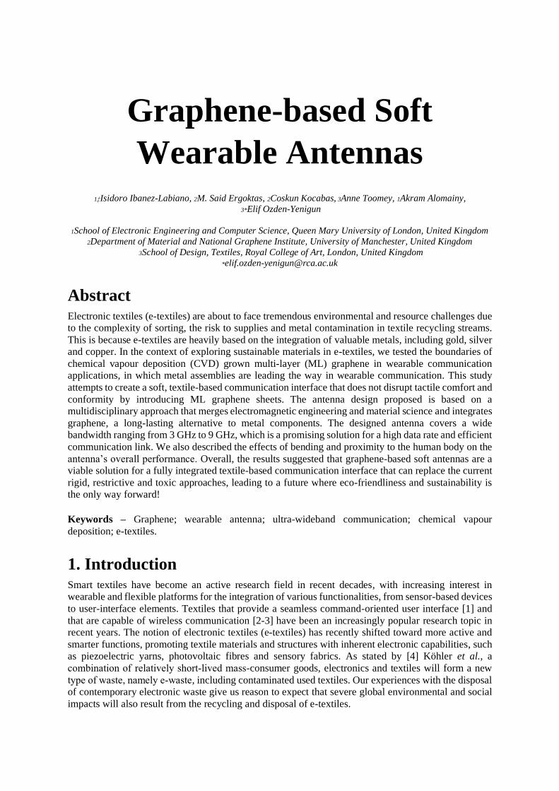
synthesized ML graphene samples was determined by Raman spectroscopy by using 532 nm 50 mW
laser source and 50x objective, as seen in Figure 1. The Raman spectrum clearly shows that the quality
of ML graphene on Ni is good, as there is no D peak detected at ~1350 cm-1 (defect peak, D) while G
peak at 1580 cm-1 exhibits a higher intensity than 2D peak at 2713 cm-1. The full width half maxima
(FWHM) values were calculated as 20.7cm-1 and 66.1cm-1 for G and 2D bands, respectively. After the
ML graphene synthesis, 20 µm thick polyethylene (PE) was laminated onto ML graphene and Ni was
etched in 1M FeCl3 solution for ~8 hours, which was followed by rinsing in deionized (DI) water.
Figure 1. Raman spectrum of CVD grown ML graphene by using a 532 nm 50 mW laser source and 50x objective.
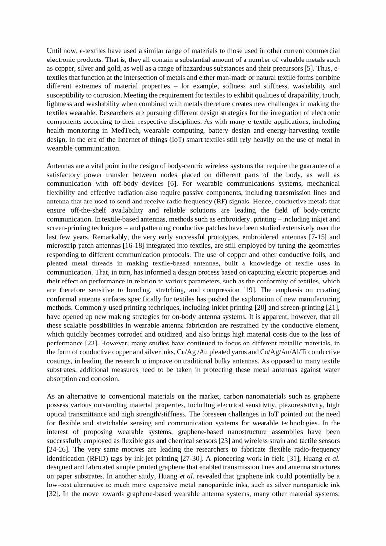
Figure 2. The fabrication process of graphene-based soft antennas. From left to right: (i) ML graphene grown on Ni foil; (ii)
ML transferred on PE sheets; (iii) cutting the patterns; (iv) graphene lamination on textiles, (v) soft graphene based antenna
with an attached SMA connector.
2.2. Fabrication of Graphene-Based Textile Antennas
The emphasis on its ability to be worn, and the antenna’s performance when coupled with the human
body, revealed an intriguing on-body presentation. In terms of electromagnetic properties, the human
body can be considered as a lossy medium associated with high dielectric constant, which in return
detunes the antenna by causing frequency shifts and affects the antenna’s gain and its efficiency [40-
41]. Among standards of communications, ultra-wideband (UWB) technology provides high capacity
with large bandwidth signals, multi-path robustness and low-power systems. UWB antennas are ideal
candidates for body-worn units in sports analytics [42], health monitoring [43-44] and positioning
systems [45]. Thus, the effect of the presence of the human body has been studied several times while
its impact on the performance of UWB antennas has been analysed [46]. Nevertheless, locating the
antenna on the body depends on several factors, such as the expected performance in such applications.
Several studies exploring different positioning of antennas for body-worn systems have pointed to the
torso as the most convenient position for combining both on-body and off-body communications [47].
The geometry of the design of the UWB wearable antenna is based on the final application [48] and the
communication channel, in both off-body and on-body communication [49]. Within wearable
technologies, antennas must be introduced to the system without disrupting the user’s performance or
comfort. Thus, in a body context wearable antennas must be compact, conformal and low profile,
making planar structured designs ideal candidates for these systems. The co-planar waveguide (CPW)
technique is a well-established solution for wearable antennas due to its reduced fabrication complexity
that avoids the misalignment of layers. This technique also enables easy integration into textiles and
facilitates new fabrication methods such as lamination processes or inkjet printing [50-52].
Figure 2 depicts the fabrication process of flexible ML graphene transferred onto textiles. The main
challenges in smart material integration arise from the fact that the antenna patches exhibit different
conformity and haptic responses from those of textiles. In order to enable full interconnectivity, the
geometry of the antenna design and its effects on the propagation channel should be carefully and
systematically evaluated. Thus, as illustrated in Figure 2, a very thin adhesive layer of EVA was applied
on ML graphene on PE samples to promote binding at the fabric interface. For successful alignment of
different components in the design, a vinyl cutter was used to create a paper mould. As a last step of
the fabrication, we placed the ML graphene on PE samples on the adhesive with the conductive side
facing up, to allow easy contact with antenna sockets/pins from MLG, and laminated it again to provide
a strong interface and mechanical stability.
ML graphene samples that were later modelled as the conductive material in antenna measurements
were tested with a four-probe method. The sheet resistance of ML graphene on the PE sample was c.a
25 Ω/sq. The conductivity of graphene could be tuned at the range of microwave to terahertz (THz)
frequencies by an external field or chemical doping. Over a broad range, the conductivity of ML-
graphene sheets found independent [53]. Using the proposed method, either bulk or thin-film specimens
can be tested by marking the thickness of the substrate.
Sheet resistance (Rs) is measured as
Rs = ρ / t (Equation 1)
where ρ is the resistivity and t the thickness material.
For a very thin sheet of material, (Rs) is
Rs = k (V/I) (Equation 2)
where the k is a geometric factor. In the case of a semi-infinite thin sheet, k is assumed to be 4.53 [54-
55].
One of the significant concerns in smart wearables is the washing durability of conductive components.
We performed a washability test by using the standard protocol in BS EN ISO 6330. Both stand-alone
ML graphene sheets on PE and ML graphene laminated cotton fabrics were washed in a Type A
reference washing machine, by following the procedure no. 4H at 40 ± 3 C, and using a detergent
without an optical brightener. The resistivity of the ML graphene sheets and the ML graphene on the
cotton fabric were also measured after 50 washing cycles.
After the transfer printing of CVD grown ML graphene onto fabric, silver-based conductive epoxy (SPI
Silver Conductive Epoxy 05000-AB) curable at room temperature was used to attach SMA 3-pin 50
Ohm connectors for the feeding. It was then cured for approximately 4 hours at 75°C. The final
prototype, as shown in Figure 3, facilitates the performance evaluation of both the graphene-radiating
component and the graphene base layer on the front, demonstrating whole-graphene antenna systems
for ultra-wideband communication.
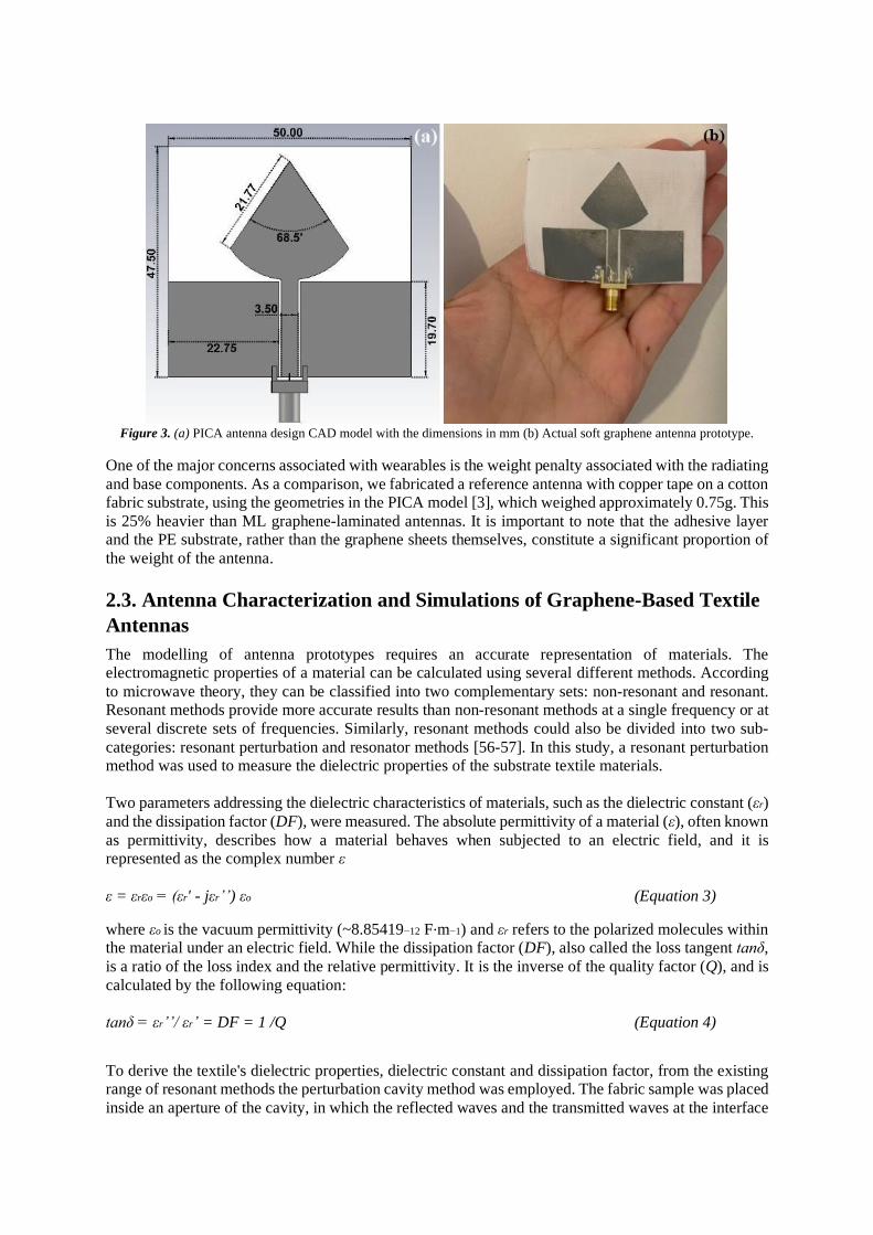
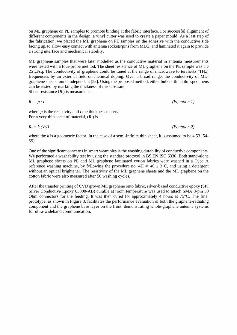
Figure 3. (a) PICA antenna design CAD model with the dimensions in mm (b) Actual soft graphene antenna prototype.
One of the major concerns associated with wearables is the weight penalty associated with the radiating
and base components. As a comparison, we fabricated a reference antenna with copper tape on a cotton
fabric substrate, using the geometries in the PICA model [3], which weighed approximately 0.75g. This
is 25% heavier than ML graphene-laminated antennas. It is important to note that the adhesive layer
and the PE substrate, rather than the graphene sheets themselves, constitute a significant proportion of
the weight of the antenna.
2.3. Antenna Characterization and Simulations of Graphene-Based Textile
Antennas
The modelling of antenna prototypes requires an accurate representation of materials. The
electromagnetic properties of a material can be calculated using several different methods. According
to microwave theory, they can be classified into two complementary sets: non-resonant and resonant.
Resonant methods provide more accurate results than non-resonant methods at a single frequency or at
several discrete sets of frequencies. Similarly, resonant methods could also be divided into two sub-
categories: resonant perturbation and resonator methods [56-57]. In this study, a resonant perturbation
method was used to measure the dielectric properties of the substrate textile materials.
Two parameters addressing the dielectric characteristics of materials, such as the dielectric constant (εr)
and the dissipation factor (DF), were measured. The absolute permittivity of a material (ε), often known
as permittivity, describes how a material behaves when subjected to an electric field, and it is represented as the complex number ε
ε = εrεo = (εr' - jεr’’) εo (Equation 3)
where εo is the vacuum permittivity (~8.85419−12 F⋅m−1) and εr refers to the polarized molecules within
the material under an electric field. While the dissipation factor (DF), also called the loss tangent tanδ,
is a ratio of the loss index and the relative permittivity. It is the inverse of the quality factor (Q), and is
calculated by the following equation:
tanδ = εr’’/ εr’ = DF = 1 /Q (Equation 4)
To derive the textile's dielectric properties, dielectric constant and dissipation factor, from the existing
range of resonant methods the perturbation cavity method was employed. The fabric sample was placed
inside an aperture of the cavity, in which the reflected waves and the transmitted waves at the interface

between the fabric and the cavity were monitored in order to determine the dielectric properties of the
textile under characterization [58]. For this specific purpose, a split cylinder resonator for material
characterization (Agilent 85072A), working at 10 GHz, and the Keysight material characterization
software (N1500A-003 Materials Measurement Suite 2015) were used. This single frequency
characterization method that ensures good control on cavity specifications and boundary conditions,
provides more accurate representation than other broadband methods such as free space. At the range
of testing frequencies, the dielectric constant of textile substrate remains unchanged [59-60].
First, the empty cavity was measured to calibrate the system. Then, placing the sample inside and using
the equations (5) and , values were retrieved
ε’ = 1 + (Vc(fc-fs)) / (2Vsfs) (Equation 5)
ε’’ = (Vc /4Vs) * ((Qc-Qs) / QcQs) (Equation 6)
where fc is the resonant frequency of the cavity when it is empty and fs is the resonant frequency when
the sample is placed inside the chamber. Qc and Qs refer to the quality factor of the cavity in an empty
state and a materially loaded state respectively. Vc and Vs represent the volume of the empty perturbation
cavity and sample volume, correspondingly. We employed this technique to characterize the textile
substrate in order to create a better numerical representation model. The textile sample was measured
and then rotated 90 degrees and measured again in the weft direction. A dielectric constant εr of 1.58
and a dissipation factor (DF) of 0.02 were obtained. The loss of bonding adhesive layer with 𝜀r ~2 and
DF ~0.02 coupled with the textile is negligible due to its relatively small thickness [61].
An essential numerical representation of an antenna is the reflection coefficient, also known as the
return loss (S11), which refers to how much of an electromagnetic wave inserted through an input port
is reflected due to a discontinuity in the transmission medium. Thus it describes the ability of the
antenna to radiate energy at a specific frequency range [62-63]. Another critical characteristic often
listed in the antenna's specifications is the far-field pattern, or radiation pattern, that describes the
intensity of the radio waves radiating from the antenna. Usually, this is a three-dimensional (3D) pattern
and is often represented by spherical coordinates. Each magnitude was normalized with respect to the
peak gain 2.83 dBi (decibels-isotropic), while retrieving the radiation pattern.
A test campaign was carried out at the Antenna Measurement Laboratory at Queen Mary University of
London [64] to perform an electromagnetic characterization of the fabric antennas. For measuring the
return losses, the antenna was connected to a vector network analyser (VNA), PNA-L Agilent N5230C.
The prototypes were placed inside a mobile antenna electromagnetic compatibility (EMC)-screened
anechoic chamber to examine the radiation patterns of the antenna under test (AUT) (Figure 4 (a)). The
EMC chamber is equipped with two open boundary quad-ridge horn antennas operating from 400 MHz
to 6 GHz (ETS-Lindgren 3164-06) and from 0.8 to 12 GHz (Satimo QH800), allowing vertical and
horizontal linear polarization measurements.
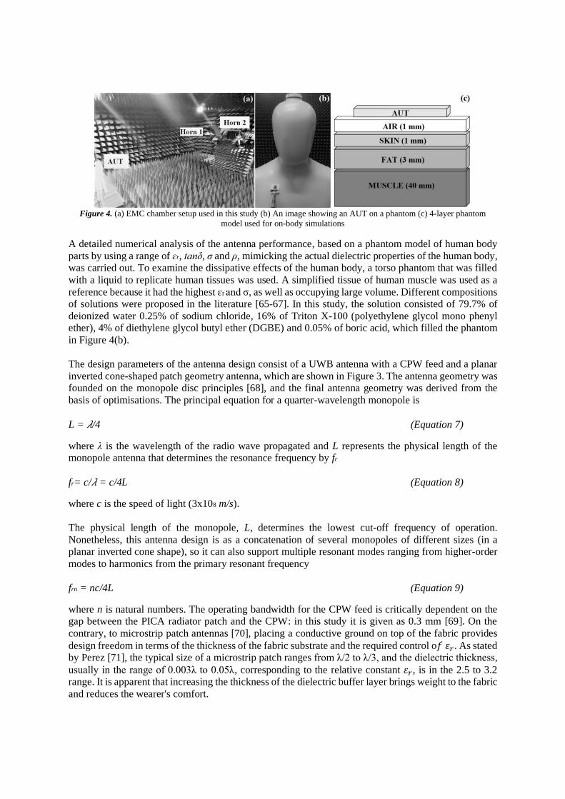
Figure 4. (a) EMC chamber setup used in this study (b) An image showing an AUT on a phantom (c) 4-layer phantom
model used for on-body simulations
A detailed numerical analysis of the antenna performance, based on a phantom model of human body
parts by using a range of ɛr, tanδ, σ and ρ, mimicking the actual dielectric properties of the human body,
was carried out. To examine the dissipative effects of the human body, a torso phantom that was filled
with a liquid to replicate human tissues was used. A simplified tissue of human muscle was used as a
reference because it had the highest ɛr and σ, as well as occupying large volume. Different compositions
of solutions were proposed in the literature [65-67]. In this study, the solution consisted of 79.7% of
deionized water 0.25% of sodium chloride, 16% of Triton X-100 (polyethylene glycol mono phenyl
ether), 4% of diethylene glycol butyl ether (DGBE) and 0.05% of boric acid, which filled the phantom
in Figure 4(b).
The design parameters of the antenna design consist of a UWB antenna with a CPW feed and a planar
inverted cone-shaped patch geometry antenna, which are shown in Figure 3. The antenna geometry was
founded on the monopole disc principles [68], and the final antenna geometry was derived from the
basis of optimisations. The principal equation for a quarter-wavelength monopole is
L = 𝜆/4 (Equation 7)
where λ is the wavelength of the radio wave propagated and L represents the physical length of the
monopole antenna that determines the resonance frequency by fr
fr= c/𝜆 = c/4L (Equation 8)
where c is the speed of light (3x10⁸ m/s).
The physical length of the monopole, L, determines the lowest cut-off frequency of operation.
Nonetheless, this antenna design is as a concatenation of several monopoles of different sizes (in a
planar inverted cone shape), so it can also support multiple resonant modes ranging from higher-order
modes to harmonics from the primary resonant frequency
frn = nc/4L (Equation 9)
where n is natural numbers. The operating bandwidth for the CPW feed is critically dependent on the
gap between the PICA radiator patch and the CPW: in this study it is given as 0.3 mm [69]. On the
contrary, to microstrip patch antennas [70], placing a conductive ground on top of the fabric provides
design freedom in terms of the thickness of the fabric substrate and the required control o𝑓 𝜀𝑟. As stated
by Perez [71], the typical size of a microstrip patch ranges from λ/2 to λ/3, and the dielectric thickness,
usually in the range of 0.003λ to 0.05λ, corresponding to the relative constant 𝜀𝑟, is in the 2.5 to 3.2
range. It is apparent that increasing the thickness of the dielectric buffer layer brings weight to the fabric
and reduces the wearer's comfort.

A numerical analysis was carried out using CST-Microwave Studio [72] to evaluate the time-domain
characteristics of the antenna structure, in which the different layers and the SMA connector were taken
into account. In CST simulations, thin ML graphene layer was constructed as a conducting material
which the current flows not along the surface but through the whole volume. This software calculates
the development of the electromagnetic fields through time at certain spatial spots and discrete-time
samples, using Maxwell's equations [73].
These antennas were also simulated on the body by using the medium of a body phantom. The phantom
model consisted of a block of four layers in total, 44 mm thick, with another 1 mm air gap placed
between the AUT. As depicted in Figure 4 (c), the thickness of body skin, fat and muscle layers were 1
mm, 3 mm and 40 mm respectively. This body representation with a 1 mm air gap, portrays the practical
implications of wearable antennas that are not placed on the body without an isolation layer that could
be another textile or a protective gel. Direct contact with the skin causes detuning of the frequency and
ultimately decreases the efficiency due to the reflective behaviour. The electromagnetic properties of
the different tissues: dielectric constant (εr), loss tangent (tanδ), conductivity (σ), and resistivity (ρ),
were retrieved from the reference studies [74-75] and are listed in Table 1. Even though the accurate representation of the human body on phantom models is challenging, electromagnetic properties of
different body compositions retrieved at 2.45 GHz has been widely accepted in testing on-body
scenarios [76-77].
Table 1 Electromagnetic properties of human tissues at 2.45 GHZ [65]
εr tanδ σ (S/m) ρ (Ω·m)
Dry skin 38.007 0.28262 1.4641 0.683
Fat 5.2801 0.14524 0.1045 9.569
Muscle 52.729 0.24194 1.7388 0.575
Woven cloth exhibits strong resistance to stretching and weak stability when bent, and fabric antennas
are no different. Hence, a brief simulation was carried out to reveal the bending effect on the input
matching of the antenna. Previous studies have suggested that bending the XZ-plane (E-plane) had a
more significant impact on the antennas' resonance length than deformation through the YZ-plane (H-
plane [78-79].
As stated in fr= c/𝜆 = c/4L
(Equation 8, there is a proportional relationship between the antenna’s resonance length and its
resonance frequency. Thus, any expansion of the length through bending or stretching would have an
impact on the antenna’s resonance. Therefore, in this study the simulation was performed bending the
antenna along the XZ-plane around two different cylinders with a diameter of 70 mm and 150 mm.
These dimensions represent parts of the human body, e.g., the arm, the leg and the shoulder, which
could be extrapolated into central angles (radians) by using the formula
θ=W/R (Equation 10)
where W is the width of the antenna and R is the radius of the cylinder. This level of bending could be
translated into degrees of angle, where the diameters of 70 mm and 150 mm correspond to 80° and
37.5° respectively.
3. Results and Discussion This study attempts to reveal the on- and off-body antenna characteristics of soft graphene-based textile
antennas. The return losses, S11, both computed and measured, were investigated in free-space, on-body
and under-bending settings. First, as a reference, we performed a computational analysis to predict the
antenna behaviour and identify the ways in which it deviates when placed on the body. Figure 5 suggests
that S11 computational results retrieved from on- and off-body measurements demonstrated a UWB
ultra-wideband behaviour rooted in the geometry of the radiator patch. The planar inverted cone-shaped
antenna behaves as a concatenation of monopoles of different sizes, instead of as a single patch. The
longest section of the radiating element, positioned in the middle of the antenna that was designed, was
around 25 mm, which formed the longest monopole of all the concatenations. The length of this
monopole determines the lowest cut-off frequency in operation, at a quarter of a wavelength for around
3 gigahertz (GHz). The dimensions of the antenna, 50 mm x 47.5 mm, are equivalent to half of the
wavelength for a frequency around 3 GHz, which also addressed the lower boundary of operation. While
computed on-body results cover a frequency band of over 2-10 GHz, off-body simulations exhibited a
return loss less than 10 dB in a slightly narrower range, from 3-10 GHz. These slight decreases in
bandwidth could be understood from the viewpoint of the dissipative medium of the body. Nevertheless,
the proposed design, whether on- or off-body, covers a wide bandwidth range that meets the
requirements of many wireless standards, including UWB communication [80-81].
Figure 5 Simulated vs Measured S11 of graphene-based antennas in off- and on-body settings.
These graphene-based PICA antennas were connected to a VNA that was calibrated with a standard
electronic calibration kit to the end of the coaxial cable to remove all the noise related to the cables and
connectors, where the same reference was used for all the measurements. As presented in Figure 5, both
measured and simulated off-body S11 results exhibited multiple resonance frequencies at a bandwidth
range of 3-9 GHz. Slight mismatches related to fabrication tolerances and unavoidable real-time losses
during testing might cause such inadequacies. Nevertheless, these graphene-based soft antennas
promise a 6 GHz operational bandwidth which is almost double in comparison with previous graphene-
based antenna prototypes reported in the literature [37].
Textile-based antennas will be exposed to prolonged stresses of various kinds during both their use and
their after-care, and thus need to be designed to conformally adhere to both irregularly shaped surfaces
and the body [82]. The making strategies in wireless signal communication is of high significance for
ensuring tactile comfort. We addressed three fabric coating parameters that affect the antenna

performance, coupled with changes in their surface conductivity. These were: (i) the quality of their
surface coverage; (ii) their vulnerability to body fluids and washing, and (iii) their changes in
conductivity as a result of cyclic bending. As described in the introduction, due to the ease of fabrication
they afford, graphene-based inks are frequently used in printing. The surface conductivity is dependent
on the lateral dimensions of graphene sheets, and also on the agglomerations of these nanoflakes. Figure
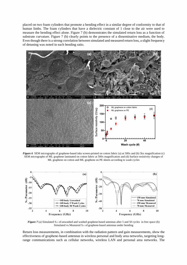
6 (a) and 6 (b) demonstrate the placing of a screen-printed graphene surface onto cotton fabrics. Surface
cracks could be associated with the liquid penetration process and evaporation of solvents in the inks.
Nevertheless, when higher surface conductivity was attempted in the work with textiles, these
nanoscopic and microscopic features caused extra challenges in achieving the level of electron
conduction. Thus, increasing layers of deposition would help this mechanism in the trade-off with tactile
comfort due to the additional weight and roughness. Figure 6 (c) shows ML graphene-laminated
surfaces on textiles. These surface traces are caused by the lamination process; however, we observed
no cracks and gaps across the textile surface. It is evident that CVD grown ML graphene sheets provided
a better quality of surface coverage compared to screen-printed conductive textile surfaces. Thus, even
though it involves an increase in the number of layers, it would be feasible to keep the soft, lightweight
nature of the coating. Video S1 in the supplementary file shows the soft nature of ML graphene on silk weave.
As in many wearable applications in e-textiles, we take extra measures due to the susceptibility of
conductive components to water and bodily fluids, such as applying hydroscopic coatings. As revealed
in Figure 6 (a) and 6 (b), water molecules can propagate through the surface cracks and damage the
structure itself, and make the screen printed surfaces vulnerable to washing. Thus, despite bringing
additional weight, the researchers explored different coating compositions on metallic based screen
printed surfaces to provide stable antenna performance with sufficient radiation efficiency after several
wash cycles [83-86]. If the conductive parts are oxidized, this functional textile becomes redundant.
Figure 6 (d) suggests the surface resistivity changes with respect to the washing cycles. ML graphene
on cotton fabric and ML graphene on PE film both showed a substantial decrease after the first wash,
reaching saturation after around 15 cycles. Figure S1 shows ‘before and after’ images of washed ML
graphene on cotton fabrics. Figure 6 (d) revealed that even though the fabric provided additional
support, the wrinkles on the surface of the fabric had a negative contribution to the surface conductivity.
Thus, we observed a substantial increase in surface resistivity of ML graphene on fabric that was
enforced by fabric shrinking compared to ML-graphene on PE sheets, as a result of washing instability
of cotton. Figure S1 demonstrated that in longer-term use, these structures would suffer more from the
risk of detaching than from oxidation or surface damage. Thus, strong interfacial bonding would also
determine the life of these fabric antennas.
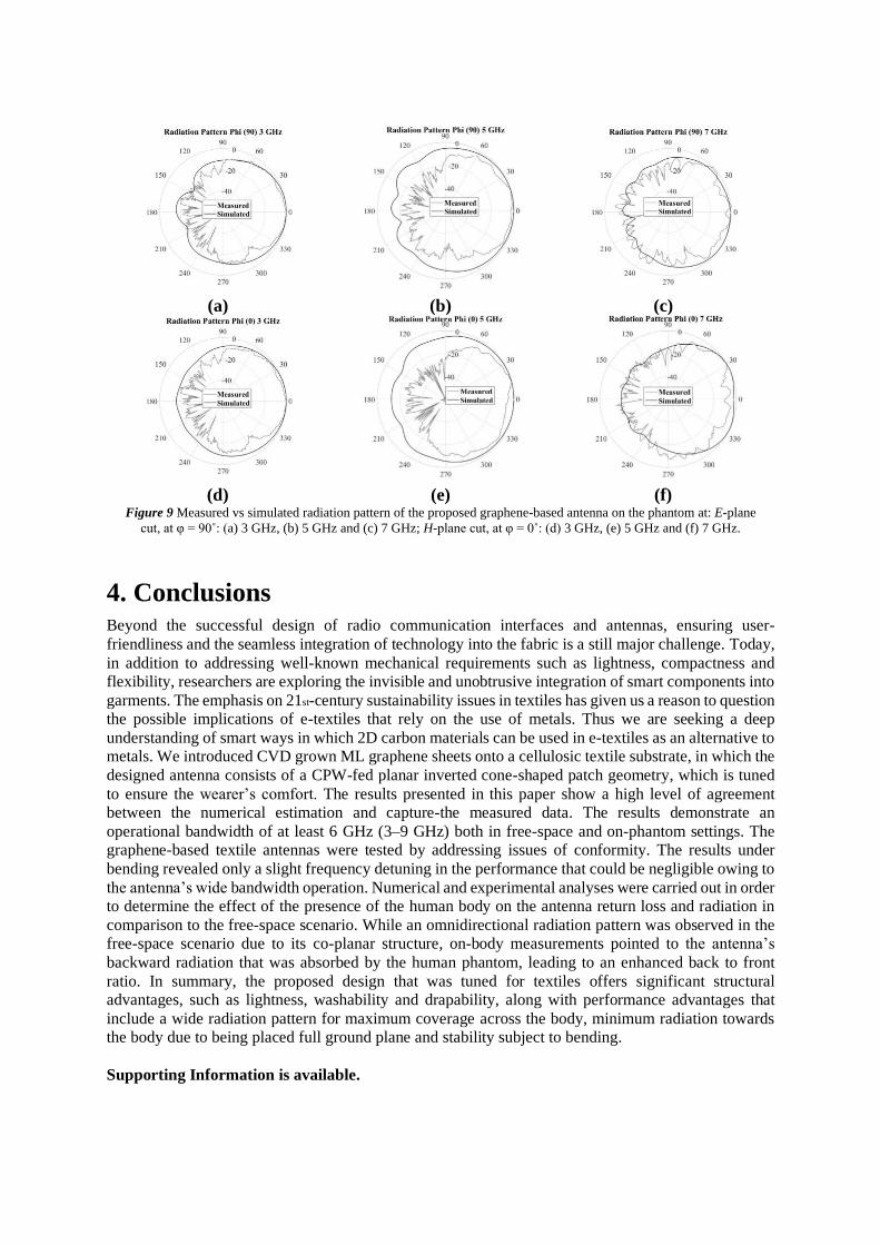
Figure 7 (a) reveals the effect of 5 and 50 wash cycles on computational S11 results of graphene-based
antennas and how the drastic change in conductivity impacted the gain. While the operational
bandwidth remained approximately constant in every three cases, S11 of graphene-based antennas
reduced and slightly shifted towards lower frequencies. After 50 wash cycles, the antenna gain showed
a -2.3 dB decrease. All these deviations in performance opened up another discussion in wearable
antennas, apart from the stability of the structure that we might look into tuneable monitoring systems.
Figure S3 presents the on-body representation of washed graphene-based antennas by depicting the S11.
It is intriguing how these graphene-based antennas suffer from the distortions associated with body
movement. Ergoktas et al. [39] performed cyclic bending and compression tests on cotton/ML
graphene/PE samples and measured the sheet resistance change over time in order to understand the
stability of the ML graphene on cotton samples for wearable applications. The results revealed that the
resistivity of ML graphene attached to cotton samples exhibited a steady profile and was not affected
by cyclic bending. The smooth and interconnected graphene sheets might have a positive contribution
to bending stability. However, it is not yet understood to what extent antennas could compensate for
these slight changes in resistivity.
Building on the knowledge of bending endurance, we examined the conformity of graphene-based
antennas to assess the effects of bending, as presented in Figure S2. To this effect, these antennas were
placed on two foam cylinders that promote a bending effect in a similar degree of conformity to that of
human limbs. The foam cylinders that have a dielectric constant of 1 close to the air were used to
measure the bending effect alone. Figure 7 (b) demonstrates the simulated return loss as a function of
substrate curvature. Figure 7 (b) clearly points to the presence of a disseminative medium, the body.
Even though there is a strong correlation between simulated and measured return loss, a slight frequency
of detuning was noted in each bending ratio.
Figure 6 SEM micrographs of graphene-based inks screen-printed on cotton fabric (a) at 500x and (b) 5kx magnification (c)
SEM micrographs of ML graphene laminated on cotton fabric at 500x magnification and (d) Surface resistivity changes of
ML graphene on cotton and ML graphene on PE sheets according to wash cycles
Figure 7 (a) Simulated S11 of unwashed and washed graphene-based antennas after 5 and 50 cycles in free space (b)
Simulated vs Measured S11 of graphene-based antennas under bending
Return loss measurements, in combination with the radiation pattern and gain measurements, show the
effectiveness of graphene-based antennas in wireless personal and body area networks, targeting long-
range communications such as cellular networks, wireless LAN and personal area networks. The

radiation pattern taken inside an anechoic chamber presented in Figure 8 was measured in order to
evaluate the radiation properties of the antenna in free space and on the phantom. Figure 8 shows the
CST-simulated radiation patterns (black) of the antenna, along with the measurements (light grey) in
free-space settings. Three main frequencies along the operation frequency band were selected as 3, 5
and 7 GHz. In each frequency, electric field E-plane (φ = 90˚) and magnetic field H-plane cuts (φ = 0˚)
were shown. The calculation of radiation patterns is provided in detail in the supporting information.
The shape of the radiation pattern is fairly consistent for the three sets of frequencies – 3, 5 and 7 GHz
– and correlated well with the simulations with minimum frequency detuning. The antenna exhibited
an omnidirectional pattern; this was expected, due to its CPW design. At higher frequencies (5 and 7
GHz i.e.), we observed slightly distorted omnidirectional patterning that could be related to the
antenna’s ability to resonate or operate in an ultra-wideband setting while the design and its dimensions
were optimized for use at 3 GHz.
(a) (b) (c)
(d) (e) (f)
Figure 8 Measured vs simulated radiation pattern of the graphene-based textile antenna in free space at: E-plane cut, at φ
= 90˚: (a) 3 GHz, (b) 5 GHz and (c) 7 GHz; H-plane cut, at φ = 0˚: (d) 3 GHz, (e) 5 GHz and (f) 7 GHz.
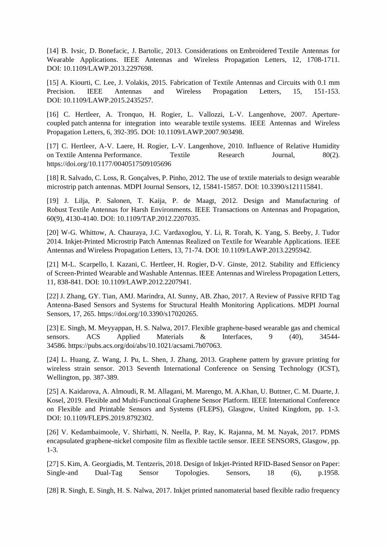
The antenna was placed on the phantom’s chest, where the antenna suffers less physical stress [77,81-
82], during the on-body measurements. The radiation pattern of the antenna was also measured, in order
to evaluate the radiation properties of the antenna on a phantom with no arms and legs [87-88]. Figure
9 (a-f) presents the measured and simulated radiation patterns for the antenna at three different
frequencies, 3 GHz, 5 GHz and 7 GHz, on the phantom. The results suggest that the on-body
measurements agree significantly with the simulated results. However, due to the absence of shielding
that isolates the antenna from the dissipative medium of the human body, the antenna radiation
performance drastically differed from the free-space measurements including the front-to-back ratio
and main radiation beam properties. In fact, the human body absorbed the reflected waves that
accompanied radiation at the front. From Figure 9 (a-f) it can be observed that the torso phantom absorbs
more energy than the numerical phantom model. This deviation in behaviour could be due to the
complexity of reproducing the human body and all its properties. Antenna design itself with a directivity
function pointing towards the centre of the curvature enhanced the intensity of surface waves and
increased the radiation into the body.
(a) (b) (c)
(d) (e) (f)
Figure 9 Measured vs simulated radiation pattern of the proposed graphene-based antenna on the phantom at: E-plane
cut, at φ = 90˚: (a) 3 GHz, (b) 5 GHz and (c) 7 GHz; H-plane cut, at φ = 0˚: (d) 3 GHz, (e) 5 GHz and (f) 7 GHz.
4. Conclusions Beyond the successful design of radio communication interfaces and antennas, ensuring user-
friendliness and the seamless integration of technology into the fabric is a still major challenge. Today,
in addition to addressing well-known mechanical requirements such as lightness, compactness and
flexibility, researchers are exploring the invisible and unobtrusive integration of smart components into
garments. The emphasis on 21st-century sustainability issues in textiles has given us a reason to question
the possible implications of e-textiles that rely on the use of metals. Thus we are seeking a deep
understanding of smart ways in which 2D carbon materials can be used in e-textiles as an alternative to
metals. We introduced CVD grown ML graphene sheets onto a cellulosic textile substrate, in which the
designed antenna consists of a CPW-fed planar inverted cone-shaped patch geometry, which is tuned
to ensure the wearer’s comfort. The results presented in this paper show a high level of agreement
between the numerical estimation and capture-the measured data. The results demonstrate an
operational bandwidth of at least 6 GHz (3–9 GHz) both in free-space and on-phantom settings. The
graphene-based textile antennas were tested by addressing issues of conformity. The results under
bending revealed only a slight frequency detuning in the performance that could be negligible owing to
the antenna’s wide bandwidth operation. Numerical and experimental analyses were carried out in order
to determine the effect of the presence of the human body on the antenna return loss and radiation in
comparison to the free-space scenario. While an omnidirectional radiation pattern was observed in the
free-space scenario due to its co-planar structure, on-body measurements pointed to the antenna’s
backward radiation that was absorbed by the human phantom, leading to an enhanced back to front
ratio. In summary, the proposed design that was tuned for textiles offers significant structural
advantages, such as lightness, washability and drapability, along with performance advantages that
include a wide radiation pattern for maximum coverage across the body, minimum radiation towards
the body due to being placed full ground plane and stability subject to bending.
Supporting Information is available.

Acknowledgements
This project has received funding from the European Union’s Horizon 2020 research and innovation
programme under grant agreement No 796640.
References
[1] S. Gorgutsa, M. Blais-Roberge, J. Viens, S. LaRochelle, Y. Messaddeq, 2016. User-Interactive and
Wireless-Communicating RF Textiles. Advanced Materials Technologies, 1 (4), 160003.
https://doi.org/10.1002/admt.201600032.
[2] L. Zhang, Z. Wang, J. Volakis, 2012. Textile antennas and sensors for body-worn applications. IEEE
Antennas and Wireless Propagation Letters, 11, 1690-1693. DOI: 10.1109/LAWP.2013.2239956.
[3] A. Alomainy, A. Sani, A. Rahman, J. Santas, Y. Hao, 2009. Transient characteristics of wearable
antennas and radio propagation channels for ultrawideband body-centric wireless communications.
IEEE Transactions on Antennas and Propagation, 57 (4 PART. 1), 875-884. DOI:
10.1109/TAP.2009.2014588.
[4] A. Köhler, L. Hilty, C. Bakker, 2011. Prospective Impacts of Electronic Textiles on Recycling and
Disposal. Journal of Industrial Ecology, 15(4), 496-511. https://doi.org/10.1111/j.1530-
9290.2011.00358.x.
[5] P. Chancerel, S. Rotter, S., 2009. Recycling-oriented characterization of small waste electrical and
electronic equipment. Waste Management, 29(8), 2336-2352.
https://doi.org/10.1016/j.wasman.2009.04.003.
[6] Peter S. Hall, Antennas and Propagation for Body-Centric Wireless Communications, Second
Edition, 9781608073764 (Book).
[7] Z. Wang, L. Zhang, Y. Bayram, J. Volakis, 2012. Embroidered Conductive Fibers on Polymer
Composite for Conformal Antennas. IEEE Transactions on Antennas and Propagation, 60(9), 4141-
4147. DOI: 10.1109/TAP.2012.2207055.
[8] T. Kaufmann, C. Fumeaux, 2013. Wearable Textile Half-Mode Substrate-Integrated
Cavity Antenna Using Embroidered Vias. IEEE Antennas and Wireless Propagation Letters, 12, 805-
808. DOI: 10.1109/LAWP.2013.2270939.
[9] L. Zhang, Z. Wang, J. Volakis, 2012. Textile Antennas and Sensors for Body-Worn Applications.
IEEE Antennas and Wireless Propagation Letters, 11, 1690-1693. DOI: 10.1109/LAWP.2013.2239956
[10] M.A.R. Osman, M. K. A. Rahim, N.A. Samsuri, H.A.M. Salim, M.F. Ali, 2011. Embroidered Fully
Textile Wearable Antenna for Medical Monitoring Applications. Progress in Electromagnetics
Research, Vol. 117, 321-337. DOI: 10.2528/PIER11041208.
[11] Z. Wang, Zheyu, L.Z. Lee, D. Psychoudakis, J. Volakis, 2014. Embroidered Multiband Body-
Worn Antenna for GSM/PCS/WLAN Communications. IEEE Transactions on Antennas and
Propagation, 62(6), 3321-3329. DOI: 10.1109/TAP.2014.2314311.
[12] J-S. Roh, Y-S. Chi, J-H. Lee, Y. Tak, S. Nam, T-J. Kang, 2010. Embroidered Wearable
Multiresonant Folded Dipole Antenna for FM Reception. IEEE Antennas and Wireless Propagation
Letters, 9, 803-806. DOI: 10.1109/LAWP.2010.2064281.
[13] R. Seager, S. Zhang, A. Chauraya, W. Whittow, Y. Vardaxoglou, T. Acti, T. Dias, 2013. Effect of
the fabrication parameters on the performance of embroidered antennas. IET Microwaves Antennas &
Propagation, 1174-1181. DOI: 10.1049/iet-map.2012.0719.
[14] B. Ivsic, D. Bonefacic, J. Bartolic, 2013. Considerations on Embroidered Textile Antennas for
Wearable Applications. IEEE Antennas and Wireless Propagation Letters, 12, 1708-1711.
DOI: 10.1109/LAWP.2013.2297698.
[15] A. Kiourti, C. Lee, J. Volakis, 2015. Fabrication of Textile Antennas and Circuits with 0.1 mm
Precision. IEEE Antennas and Wireless Propagation Letters, 15, 151-153.
DOI: 10.1109/LAWP.2015.2435257.
[16] C. Hertleer, A. Tronquo, H. Rogier, L. Vallozzi, L-V. Langenhove, 2007. Aperture-
coupled patch antenna for integration into wearable textile systems. IEEE Antennas and Wireless
Propagation Letters, 6, 392-395. DOI: 10.1109/LAWP.2007.903498.
[17] C. Hertleer, A-V. Laere, H. Rogier, L-V. Langenhove, 2010. Influence of Relative Humidity
on Textile Antenna Performance. Textile Research Journal, 80(2).
https://doi.org/10.1177/0040517509105696
[18] R. Salvado, C. Loss, R. Gonçalves, P. Pinho, 2012. The use of textile materials to design wearable
microstrip patch antennas. MDPI Journal Sensors, 12, 15841-15857. DOI: 10.3390/s121115841.
[19] J. Lilja, P. Salonen, T. Kaija, P. de Maagt, 2012. Design and Manufacturing of
Robust Textile Antennas for Harsh Environments. IEEE Transactions on Antennas and Propagation,
60(9), 4130-4140. DOI: 10.1109/TAP.2012.2207035.
[20] W-G. Whittow, A. Chauraya, J.C. Vardaxoglou, Y. Li, R. Torah, K. Yang, S. Beeby, J. Tudor
2014. Inkjet-Printed Microstrip Patch Antennas Realized on Textile for Wearable Applications. IEEE
Antennas and Wireless Propagation Letters, 13, 71-74. DOI: 10.1109/LAWP.2013.2295942.
[21] M-L. Scarpello, I. Kazani, C. Hertleer, H. Rogier, D-V. Ginste, 2012. Stability and Efficiency
of Screen-Printed Wearable and Washable Antennas. IEEE Antennas and Wireless Propagation Letters,
11, 838-841. DOI: 10.1109/LAWP.2012.2207941.
[22] J. Zhang, GY. Tian, AMJ. Marindra, AI. Sunny, AB. Zhao, 2017. A Review of Passive RFID Tag
Antenna-Based Sensors and Systems for Structural Health Monitoring Applications. MDPI Journal
Sensors, 17, 265. https://doi.org/10.3390/s17020265.
[23] E. Singh, M. Meyyappan, H. S. Nalwa, 2017. Flexible graphene-based wearable gas and chemical
sensors. ACS Applied Materials & Interfaces, 9 (40), 34544-
34586. https://pubs.acs.org/doi/abs/10.1021/acsami.7b07063.
[24] L. Huang, Z. Wang, J. Pu, L. Shen, J. Zhang, 2013. Graphene pattern by gravure printing for
wireless strain sensor. 2013 Seventh International Conference on Sensing Technology (ICST),
Wellington, pp. 387-389.
[25] A. Kaidarova, A. Almoudi, R. M. Allagani, M. Marengo, M. A.Khan, U. Buttner, C. M. Duarte, J.
Kosel, 2019. Flexible and Multi-Functional Graphene Sensor Platform. IEEE International Conference
on Flexible and Printable Sensors and Systems (FLEPS), Glasgow, United Kingdom, pp. 1-3.
DOI: 10.1109/FLEPS.2019.8792302.
[26] V. Kedambaimoole, V. Shirhatti, N. Neella, P. Ray, K. Rajanna, M. M. Nayak, 2017. PDMS
encapsulated graphene-nickel composite film as flexible tactile sensor. IEEE SENSORS, Glasgow, pp.
1-3.
[27] S. Kim, A. Georgiadis, M. Tentzeris, 2018. Design of Inkjet-Printed RFID-Based Sensor on Paper:
Single-and Dual-Tag Sensor Topologies. Sensors, 18 (6), p.1958.
[28] R. Singh, E. Singh, H. S. Nalwa, 2017. Inkjet printed nanomaterial based flexible radio frequency

identification (RFID) tag sensors for the internet of nano things. RSC Advances, 7 (77), 48597- 48630.
[29] M. Rizwan, A. A. Kutty, M. Kgwadi, T. D. Drysdale, L. Sydänheimo, L. Ukkonen, J. Virkki, J,
2017. Possibilities of Fabricating Copper-Based RFID Tags With Photonic-Sintered Inkjet Printing and
Thermal Transfer Printing. IEEE Antennas and Wireless Propagation Letters, 16, pp.1828-1831.
[30] M. Akbari, H. He, J. Juuti, M.M. Tentzeris, J. Virkki, L. Ukkonen, 2017. 3D Printed and
Photonically Cured Graphene UHF RFID Tags on Textile, Wood, and Cardboard Substrates.
International Journal of Antennas and Propagation, 7327398. https://doi.org/10.1155/2017/7327398.
[31] X. Huang, T. Leng, M. Zhu, X. Zhang, J-C. Chen, K. Chang, M. Aqeeli, A.K. Geim, K.S.
Novoselov, Z. Hu, 2015. Highly Flexible and Conductive Printed Graphene for Wireless Wearable
Communications Applications. Scientific Reports 5, 18298. https://doi.org/10.1038/srep18298.
[32] X. Huang, T. Leng, K. Chang, J-C. Chen, K.S. Novoselov, Z. Hu, 2016. Graphene radio frequency
and microwave passive components for low cost wearable electronics. IOP 2D Materials, 3(2), 025021.
https://doi.org/10.1088/2053-1583/3/2/025021.
[33] S. Anand, D.S. Kumar, R.J. Wu, M. Chavali, 2014. Graphene nanoribbon based terahertz antenna
on polyimide substrate. Optik - International Journal for Light and Electron Optics, 125(19), 5546-
5549. DOI: 10.1016/j.ijleo.2014.06.085.
[34] M. Akbari, M.W.A. Khan, M. Hasani, T. Björninen, L. Sydänheimo, L. Ukkonen, 2016.
Fabrication and characterization of graphene antenna for low-cost and environmentally friendly RFID
tags. IEEE Antennas and Wireless Propagation Letters, 15, 1569-1572. DOI:
10.1109/LAWP.2015.2498944.
[35] M. Akbari, J. Virkki, L. Sydänheimo, L. Ukkonen, 2016. Toward Graphene-Based Passive UHF
RFID Textile Tags: A Reliability Study. IEEE Transactions on Device and Materials Reliability, 16 (3),
1-1. DOI: 10.1109/TDMR.2016.2582261.
[36] S. Kosuga, R. Suga, O. Hashimoto, S. Koh, 2017. Graphene-based optically transparent dipole
antenna. Appl. Phys. Lett. 110, 233102. https://doi.org/10.1063/1.4984956.
[37] M. Grande, G. Valerio Bianco, D. Laneve, P. Capezzuto, V. Petruzzelli, M. Scalora, F.
Prudenzano, G. Bruno, A. D'Orazio, 2018. Optically transparent wideband CVD graphene-based
microwave antennas. Appl. Phys. Lett. 112, 251103. https://doi.org/10.1063/1.5037409.
[38] K. Jaakkola, V. Ermolov, P.G. Karagiannidis, S.A. Hodge, L. Lombardi, X. Zhang, R.
Grenman, H. Sandberg, A. Lombardo, A.C. Ferrari, 2019. Screen-printed and spray coated graphene-
based RFID transponders. IOP 2D Materials, 7(1), 015019. https://doi.org/10.1088/2053-1583/ab48d8.
[39] Ergoktas, M.S., Bakan, G., Steiner, P., Bartlam, C., Malevich, Y., Yenigun, E.O., He, G., Karim,
N., Cataldi, P., Bissett, M. and Kinloch, I.A., 2020. Graphene-enabled adaptive infrared textiles. arXiv
preprint arXiv:2004.08629.
[40] S.R. Chowdhury, K. Ali, 2016. Effects of human body on antenna performance: A quantitative
study. 19th International Conference on Computer and Information Technology (ICCIT), 16692823.
DOI: 10.1109/ICCITECHN.2016.7860178.
[41] N-H-A. Rahman, Y. Yamada, M-S-A. Nordin, 2019. Analysis on the Effects of the Human Body
on the Performance of Electro-Textile Antennas for Wearable Monitoring and Tracking Application.
MDPI Materials, 12(10). DOI: 10.3390/ma12101636.
[42] S. Minyoung, Chapter 12 - Wearable sensors for athletes, Electronic Textiles: Smart Fabrics and
Wearable Technology, Woodhead Publishing, 2015.
[43] C.S. Survase, V.V. Deshmukh, 2013. Simulation and Design of Wearable Antenna for
Telemedicine Application. International Journal of Advanced Research in Electrical, Electronics and
Instrumentation Engineering, 2(5).
[44] L. Corchia, G. Monti, E. de Benedetto, L. Tarricone, 2017. Wearable Antennas for Remote Health
Care Monitoring Systems. International Journal of Antennas and Propagation, 3012341.
https://doi.org/10.1155/2017/3012341.
[45] J. Singh, P. Kalra, S. Singh, E. Sindhu, 2016. High Gain Textile Rectangular Microstrip Patch
Antenna design employing Denim Substrate for Satellite Space to Earth downlink applications.
International Conference on Global Trends in Signal Processing, Information Computing and
Communication. DOI: 10.1109/ICGTSPICC.2016.7955324.
[46] A.A. Wael, M.M. Asmaa, A.M. Darwish, 2016. Compact UWB wearable planar antenna mounted
on different phantoms and human body. Microwave and Optical Technology Letters, 58(10), 2531-
2536. https://doi.org/10.1002/mop.30088.
[47] L. Januszkiewicz, P. Di Barba, S. Hausman, 2016. Field-Based Optimal Placement of Antennas
for Body-Worn Wireless Sensors. MDPI Sensors, 16(5), 713. https://doi.org/10.3390/s16050713.
[48] H.G. Schantz, 2003. Introduction to ultra-wideband antennas. IEEE Conf. Ultra Wideband Syst.
Technol, 1–9. DOI: 10.1109/UWBST.2003.1267792.
[49] S. Yan, P-J. Soh, G.A.E. Vandenbosch, 2018. Wearable Ultrawideband Technology—A Review
of Ultrawideband Antennas, Propagation Channels, and Applications in Wireless Body Area Networks.
IEEE Access, 6, 42177 – 42185. DOI: 10.1109/ACCESS.2018.2861704.
[50] L. Qingshuang, Y. Liu, 2014. CPW-fed wearable textile L-shape patch antenna. 3rd Asia-Pacific
Conference on Antennas and Propagation, 14824628. DOI: 10.1109/APCAP.2014.6992526.
[51] U. Farooq, A. Iftikhar, A. Fida, M.S. Kahn, M.F. Shafique, S.M. Asif, R.M. Shubair, 2019. Design
of a 1×4 CPW Microstrip Antenna Array on PET substrate for Biomedical Applications. IEEE
International Symposium on Antennas and Propagation and USNC-URSI Radio Science Meeting,
19114607. DOI: 10.1109/APUSNCURSINRSM.2019.8889355.
[52] F. Wang, T. Arslan, 2016. Inkjet-printed antenna on flexible substrate for wearable microwave
imaging applications. Loughborough Antennas & Propagation Conference (LAPC), 16582324.
DOI: 10.1109/LAPC.2016.7807499.
[53] M. Grande, G. V. Bianco, M. A. Vincenti, D. Ceglia, P. Capezzuto, M. Scalora, A.
D’Orazio, G. Bruno, 2015. Optically Transparent Microwave Polarizer Based On Quasi-Metallic
Graphene. Sci Rep 5, 17083. https://doi.org/10.1038/srep17083
[54] Four-Point Probe Manual.http://four-point-probes.com/four-point-probe-manual/, 2020 (accessed
12 February 2020).
[55] S.B. Kjeldby, O.M. Evenstad, S.P. Cooil, J.W. Wells, 2017. Probing dimensionality using a
simplified 4-probe method. IOP Journal of Physics: Condensed Matter, 29,394008.
https://doi.org/10.1088/1361-648X/aa8296.
[56] S. Sankaralingam, G. Bhaskar, 2010. Determination of Dielectric Constant of Fabric Materials and
Their Use as Substrates for Design and Development of Antennas for Wearable Applications. IEEE
Transactions on Instrumentation and Measurements, 59(12), 3122-3130.
DOI: 10.1109/TIM.2010.2063090.

[57] J. Lesnikowski, 2012. Dielectric permittivity measurement methods of textile substrate of textile
transmission lines Przeglad Elektrotechniczny 0033-2097 R.88 NR-3.
[58] H. Henson, J.L. Sexton, Microwave Electronics, John Wiley & Sons, Chichester, 2004, 142.
[59] W.E. Morton, 2008. Physical Properties of Textile Fibres, 4th Edition. The Textile Institute CRC
Press Woodhead 360 Publishing Ltd.
[60] S. Sankaralingam, B. Gupta, 2010. Determination of Dielectric Constant of Fabric Materials and
Their Use as Substrates for Design and Development of Antennas for Wearable Applications. IEEE
Transactions on Instrumentation and Measurement, vol. 59, no. 12, pp. 3122-3130.
[61] A. M. Faiz, N. Gogosh, S. A. Khan, M.F. Shafique, 2014. Effects of an ordinary adhesive material
on radiation characteristics of a dielectric resonator antenna. Microwave and Optical Technology
Letters, Volume56, Issue6. https://doi.org/10.1002/mop.28349.
[62] D.M. Pozar, Microwave Engineering, Hoboken NJ Wiley & Sons, 2009.
[63] C.A. Balanis, Antenna theory: analysis and design, Hoboken NJ John Wiley & Sons, 2012.
[64] Antennas & Electromagnetics Research Group, Queen Mary University of London.
http://antennas.eecs.qmul.ac.uk/facilities/antenna-measurement-laboratory/, 2020 (accessed 12
February 2020).
[65] T. Takimoto, T. Onishi, K. Saito, M. Takahashi, S. Uebayashi, K. Ito, 2007. Characteristics of
biological tissue equivalent phantoms applied to UWB communications. Elec. Commun. Japan (Part I:
Commun.), 90(5), 48-55. DOI: 10.1002/ecja.20300.
[66] J. Garrett, E. Fear, 2014. Stable and flexible materials to mimic the dielectric properties of human
soft tissues. IEEE Antennas Wireless Propagation Letters, 13, 599-602.
DOI: 10.1109/LAWP.2014.2312925.
[67] G.A. Conway, W.G. Scanlon, 2009. Antennas for Over-Body-Surface Communication at 2.45
GHz. IEEE Transactions on Antennas and Propagation, 57(4), 844-855, 10560828.
DOI: 10.1109/TAP.2009.2014525.
[68] J. Liang, L. Guo, C.C. Chiau, X. Chen, C.G. Parini, 2005. Study of CPW-fed circular disc
monopole antenna for ultra wideband applications. IEE Proceedings - Microwaves, Antennas and
Propagation, 152(6), 520-526. DOI: 10.1049/ip-map:20045179.
[69] B. Allen, M. Dohler, E. Okon, W. Malik, A. Brown, D. Edwards, Ultra-Wideband Antennas and
Propagation: For Communications, Radar and Imaging, Technology & Engineering, John Wiley &
Sons, 2006.
[70] E.A. Bengio, D. Senic, L.W. Taylor, R.J. Headrick, M. King, P. Chen, C.A. Little, J. Ladbury, C.J.
Long, C.L. Holloway, A. Babakhani, J.C. Booth, N.D. Orloff, M. Pasquali, 2019. Carbon nanotube thin
film patch antennas for wireless communications. Appl. Phys. Lett. 114(2), 203102.
https://doi.org/10.1063/1.5093327.
[71] R. Perez, Interference into Circuits, Wireless Communications Design Handbook, 1998.
[72] CST Microwave Studio. https://www.3ds.com/products-services/simulia/products/cst-studio-
suite/?utm_source=cst.com&utm_medium=301&utm_campaign=cst, 2020 (accessed 12 February
2020).
[73] G. Lehner, Electromagnetic Field Theory for Engineers and Physicits, Springer Science & Business
Media Book, 2010.

[74] A.A. Azlan, M.T.Ali, M.Z. Awang, M.F. Jamlos, 2014. A Simulation of Single Patch Antenna
with Phantom Tissue for ISM Band. National Conference on Medical at Center of Medical Electronic
Politeknik Shah Alam.
[75] Institute for Applied Physics, Dielectric properties of body tissues in the frequency range 10 Hz -
100 GHz Italian National Research Council. http://niremf.ifac.cnr.it/tissprop/, 2020 (accessed 12
February 2020).
[76] S. Castelló-Palacios, A. Vallés-Lluch, C. Garcia-Pardo, A. Fornes-Leal, N. Cardona, 2017.
Formulas for easy-to-prepare tailored phantoms at 2.4 GHz ISM band. 11th International Symposium
on Medical Information and Communication Technology (ISMICT), Lisbon, 2017, pp. 27-31, doi:
10.1109/ISMICT.2017.7891760.
[77] S. M. Abbas, H. Zahra, R. Hashmi, K. P. Esselle, J. L. Volakis, 2019. Compact On-Body Antennas
for Wearable Communication Systems. International Workshop on Antenna Technology (iWAT),
Miami, FL, USA, 2019, pp. 65-66, doi: 10.1109/IWAT.2019.8730638.
[78] P. Salonen, Y. Rahmat-Samii, 2006. Textile antennas: Effects of antenna bending on input
matching and impedance bandwidth. First European Conference on Antennas and Propagation, 2164-
3342. DOI: 10.1109/EUCAP.2006.4584859.
[79] Y. Sun, S.W. Cheung, T.I. Yuk, 2014. Design of a textile ultra-wideband antenna with stable
performance for body-centric wireless communications. IET Microwaves, Antennas & Propagation,
8(15), 1363-1375. DOI: 10.1049/iet-map.2013.0658.
[80] I. Oppermann, M. Hamalainen, J. Linatti, UWB Theory and Applications, John Wiley & Sons,
Chichester, 2004, 0-470-86917-8.
[81] A. Alomainy, Y. Hao, C.G. Parini, P.S. Hall, 2005. Comparison Between Two Different Antennas
for UWB On-Body Propagation Measurements. IEEE Antennas and Wireless Propagation Letters, 4(1),
31-34. DOI: 10.1109/LAWP.2005.844143.
[82] J.C. Yang, J. Mun, S.Y. Kwon, S. Park, Z. Bao, S. Park, 2019. Electronic Skin: Recent Progress
and Future Prospects for Skin-Attachable Devices for Health Monitoring, Robotics, and Prosthetics.
Advance Materials, 31(48), 1904765. DOI: 10.1002/adma.201904765.
[83] T. Kellomaki, J. Virkki, S. Merilampi, L. Ukkonen, 2012. Towards Washable Wearable Antennas:
A Comparison of Coating Materials for Screen-Printed Textile-Based UHF RFID Tags. Hindawi
Publishing Corporation International Journal of Antennas and Propagation Volume 2012, Article ID
476570, 11 pages. DOI:10.1155/2012/476570
[84] M. L. Scarpello, I. Kazani, C. Hertleer, H. Rogier, D. Vande Ginste, 2012. Stability and Efficiency
of Screen-Printed Wearable and Washable Antenna. IEEE Antennas and Wireless Propagation Letters,
vol. 11, pp. 838-841. DOI: 10.1109/LAWP.2012.2207941.
[85] I. Kazani, M.L. Scarpello, C. Hertleer, H. Rogier, G. de Mey, G. Guxho, L. Van Langenhove,
2012. Washable Screen Printed Textile Antennas. Advances in Science and Technology 80, 118–122.
https://doi.org/10.4028/www.scientific.net/ast.80.118
[86] K. Kazani, F. Declercq, M.L. Scarpello, C. Hertleer, H. Rogier, V. Ginste, G. de Mey, G. Guxho,
L. Van Langenhove, 2014. Performance Study of Screen-Printed Textile Antennas after Repeated
Washing. Autex Research Journal, Volume 14: Issue 2. https://doi.org/10.2478/v10304-012-0049-x.
[87] A.T. Mobashsher, A.M. Abbosh, 2015. Artificial Human Phantoms: Human Proxy in Testing
Microwave Apparatuses That Have Electromagnetic Interaction with the Human Body. IEEE
Microwave Magazine 16(6). DOI: 10.1109/MMM.2015.2419772.

[88] S. Castello-Palacios, A. Valles-Lluch, C. Garcia-Pardo, A. Fornes-Leal, N. Cardona, 2017.
Formulas for Easy-To-Prepare Tailored Phantoms at 2.4 GHz ISM Band. 11th International Symposium
on Medical Information and Communication Technology (ISMICT), 16792664.
DOI: 10.1109/ISMICT.2017.7891760.


