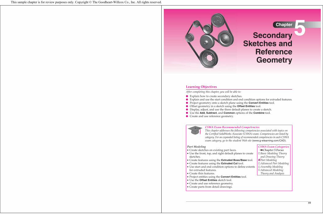
5
99
Secondary Sketches and
Reference Geometry
Learning ObjectivesAfter completing this chapter, you will be able to:
Explain how to create secondary sketches.Explain and use the start condition and end condition options for extruded features.Project geometry onto a sketch plane using the Convert Entities tool.Offset geometry in a sketch using the Offset Entities tool.Display, adjust, and use the three default planes to create a sketch.Use the Add, Subtract, and Common options of the Combine tool.Create and use reference geometry.
CSWA Exam Recommended CompetenciesThis chapter addresses the following competencies associated with topics on the Certifi ed SolidWorks Associate (CSWA) exam. Competencies are listed by category. For an expanded listing of recommended competencies in each CSWA exam category, go to the student Web site (www.g-wlearning.com/CAD).
Part ModelingCreate sketches on existing part faces.Use the front, top, and right default planes to create sketches.Create features using the Extruded Boss/Base tool.Create features using the Extruded Cut tool.Use start and end condition options to defi ne extents for extruded features.Create thin features.Project entities using the Convert Entities tool.Use the Offset Entities sketch tool.Create and use reference geometry.Create parts from detail drawings.
CSWA Exam CategoriesChapter 5 Focus
Basic Modeling Theory and Drawing TheoryPart ModelingAdvanced Part ModelingAssembly ModelingAdvanced Modeling Theory and Analysis
This sample chapter is for review purposes only. Copyright © The Goodheart-Willcox Co., Inc. All rights reserved.
Ands jspois a thspo cnb angoxu igcuostues tre poiust piod agousgas on few ousi zougosa eossougsgo.
100 Learning SolidWorks 2010
Creating Secondary Sketches and Adding Features
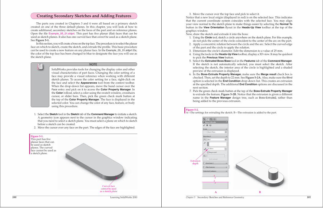
The parts you created in Chapters 3 and 4 were all based on a primary sketch created on one of the three default planes. In this chapter, you will look at how to create additional, secondary sketches on the faces of the part and on reference planes. Open the fi le Example_05_01.sldprt. This part has fi ve planar (fl at) faces that can be used as sketch planes. It also has one curved face that cannot be used as a sketch plane. See Figure 5-1.
In this section, you will create a boss on the top face. The procedure is to select the planar face on which to sketch, create the sketch, and extrude the profi le. This basic procedure can be used to create a new feature on any planar face. In the Example_05_01.sldprt fi le, the color of the top face has been changed to blue to designate the face you will use as the sketch plane.
NOTE
SolidWorks provides tools for changing the display color and other visual characteristics of part faces. Changing the color setting of a face may provide a visual reference when working with different sketch planes. To access the color setting for a face, right-click on the face and select the Appearances tool from the context toolbar. When the drop-down list appears, move the hand cursor over the Face entry and pick on it to access the Color Property Manager. In the Color rollout, select a color using the swatch window, crosshairs cursor, or slider bars. Then, pick the green check mark button at the top of the Color Property Manager. The face is displayed in the selected color. You can change the color of any face, feature, or body using this procedure.
1. Select the Sketch tool in the Sketch tab of the Command Manager to initiate a sketch. A geometry icon appears next to the cursor in the graphics window indicating that you need to select a sketch plane. You must select a plane on which to sketch before a sketch can be created.
2. Move the cursor over any face on the part. The edges of the face are highlighted.
Figure 5-1.This part has fi ve planar faces that can be used as sketch planes. The curved face cannot be used as a sketch plane.
Curved facecannot be used
as a sketch plane
Chapter 5 Secondary Sketches and Reference Geometry 101
3. Move the cursor over the top face and pick to select it.Notice that a new local origin (displayed in red) is on the selected face. This indicatesthat the current coordinate system coincides with the selected face. You may alignyour view normal to the sketch plane to make things easier by selecting the Normal Tobutton in the View Orientation flyout in the Heads-Up View toolbar at the top of thegraphics window.Now, draw the sketch and extrude it into the boss:
1. Using the Circle tool, sketch a circle anywhere on the sketch plane. For this example,do not pick the center of the circle coincident to the center of the arc on the part.
2. Apply a concentric relation between the circle and the arc. Select the curved edgeof the part and the circle to apply the relation.
3. Dimension the circle’s diameter. Edit the dimension to a value of 25 mm.4. Using the tools in the Heads-Up View toolbar, display a 3D view. It may be quickest
to pick the Previous View button.5. Select the Extruded Boss/Base tool in the Features tab of the Command Manager.
If the sketch is not automatically selected, you must select the sketch. Afterselecting the sketch, the interior area of the circle is highlighted and a shadedpreview of the extrusion is displayed.
6. In the Boss-Extrude Property Manager, make sure the Merge result check box ischecked. Then, set the depth to 22 mm. See Figure 5-2A. Also, make sure the Blindoption is selected in the End Condition drop-down list. This creates an extrusionat the specified depth. The additional End Condition options are discussed in thenext section.
7. Pick the green check mark button at the top of the Boss-Extrude Property Managerto extrude the feature, Figure 5-2B. Notice that the extrusion is given a differentname in the Feature Manager design tree, such as Boss-Extrude2, rather thanbeing added to the previous extrusion.
A B
Extrusiondepth
Figure 5-2.A—The settings for extruding the sketch. B—The extrusion is added to the part.
Ands jspois a thspo cnb angoxu igcuostues tre poiust piod agousgas on few ousi zougosa eossougsgo.
102 Learning SolidWorks 2010
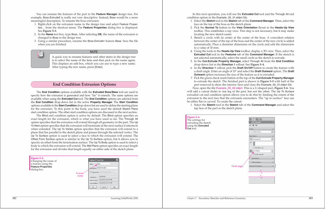
You can rename the features of the part in the Feature Manager design tree. For example, Boss-Extrude2 is really not very descriptive. Instead, Boss would be a more meaningful description. To rename the boss extrusion: 1. Right-click on the extrusion name in the design tree and select Feature Proper-
ties… from the shortcut menu. The Feature Properties dialog box is displayed. See Figure 5-3.
2. In the Name text box, type Boss. After selecting OK, the name of the extrusion is changed to Boss in the design tree.
3. Using a similar procedure, rename the Boss-Extrude1 feature Base. Save the fi le when you are fi nished.
NOTE
A quick way to rename features and other items in the design tree is to select the name of the item and then pick on the name again. This displays an edit box, which you can use to type a new name. After typing the new name, press [Enter].
End Condition Extrusion Options
The End Condition options available with the Extruded Boss/Base tool are used to specify how the extrusion is generated and how “far” it extends. The same options are available when using the Extruded Cut tool. The End Condition options are selected from the End Condition drop-down list in the active Property Manager. The Start Conditionoptions available in the Start Condition drop-down list are used to defi ne the starting plane for the extrusion. To this point in the book, you have used the default Sketch Planestart condition option. The other start condition options are discussed in the next section.
The Blind end condition option is active by default. The Blind option specifi es an exact length for the extrusion, which is what you have used so far. The Through Alloption specifi es that the extrusion will extend through all geometry in the part. The Up To Next option specifi es that the extrusion will terminate at the next surface it intersects when extended. The Up To Vertex option specifi es that the extrusion will extend to a plane that lies parallel to the sketch plane and passes through the selected vertex. The Up To Surface option is used to select a face to which the extrusion will extend. The Offset From Surface option is similar to the Up To Surface option, but it allows you to specify an offset from the termination surface. The Up To Body option is used to select a body to which the extrusion will extend. The Mid Plane option specifi es an exact length for the extrusion and divides that length equally on either side of the sketch plane.
Figure 5-3.Changing the name of a feature using the Feature Propertiesdialog box.
Featurename
Chapter 5 Secondary Sketches and Reference Geometry 103
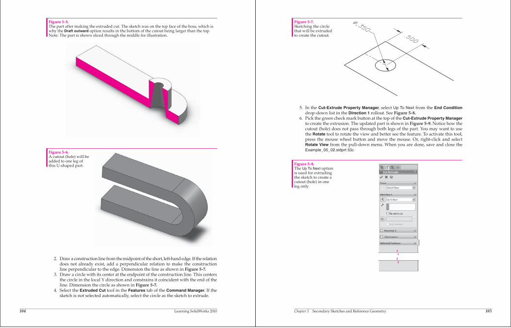
In this next operation, you will use the Extruded Cut tool and the Through All endcondition option in the Example_05_01.sldprt file.
1. Select the Sketch tool in the Sketch tab of the Command Manager. Then, select theface on the top of the boss as the sketch plane.
2. Pick the Normal To button in the View Orientation flyout in the Heads-Up Viewtoolbar. This establishes a top view. This step is not necessary, but it may makelocating the new sketch easier.
3. Sketch a circle with its center at the center of the boss. A coincident relationbetween the center of the top of the boss and the center of the new circle is addedautomatically. Place a diameter dimension on the circle and edit the dimensionto a value of 10 mm.
4. Using the tools in the Heads-Up View toolbar, display a 3D view. Then, select theExtruded Cut tool in the Features tab of the Command Manager. If the sketch isnot selected automatically, select the small circle as the sketch to extrude.
5. In the Cut-Extrude Property Manager, select Through All from the End Conditiondrop-down list in the Direction 1 rollout. See Figure 5-4.
6. In the Direction 1 rollout, pick the Draft On/Off button to create the feature witha draft angle. Enter an angle of 10 and select the Draft Outward option. The Draft Outward option increases the size of the feature as it is extruded.
7. Pick the green check mark button at the top of the Cut-Extrude Property Managerto extrude the sketch. The finished part is shown in Figure 5-5 with half of thepart removed to show the interior. Save and close the Example_05_01.sldprt file.
Now, open the file Example_05_02.sldprt. This is a U-shaped part, Figure 5-6. Youwill add a cutout (hole) to one leg of the part, but not the other. The Up To Surfaceextruded cut end condition option allows you to do this by limiting the extent of theextrusion to the next face that the extrusion encounters. The “up to surface” face canbe either flat or curved. To create the cutout:
1. Select the Sketch tool in the Sketch tab of the Command Manager and select thetop face of the part as the sketch plane.
Figure 5-4.The settings forextruding the sketchusing the Extruded Cut tool.
Draft angle
104 Learning SolidWorks 2010
2. Draw a construction line from the midpoint of the short, left-hand edge. If the relationdoes not already exist, add a perpendicular relation to make the constructionline perpendicular to the edge. Dimension the line as shown in Figure 5-7.
3. Draw a circle with its center at the endpoint of the construction line. This centersthe circle in the local Y direction and constrains it coincident with the end of theline. Dimension the circle as shown in Figure 5-7.
4. Select the Extruded Cut tool in the Features tab of the Command Manager. If thesketch is not selected automatically, select the circle as the sketch to extrude.
Figure 5-5.The part after making the extruded cut. The sketch was on the top face of the boss, which iswhy the Draft outward option results in the bottom of the cutout being larger than the top.Note: The part is shown sliced through the middle for illustration.
Figure 5-6.A cutout (hole) will beadded to one leg ofthis U-shaped part.
Chapter 5 Secondary Sketches and Reference Geometry 105
5. In the Cut-Extrude Property Manager, select Up To Next from the End Conditiondrop-down list in the Direction 1 rollout. See Figure 5-8.
6. Pick the green check mark button at the top of the Cut-Extrude Property Managerto create the extrusion. The updated part is shown in Figure 5-9. Notice how thecutout (hole) does not pass through both legs of the part. You may want to usethe Rotate tool to rotate the view and better see the feature. To activate this tool,press the mouse wheel button and move the mouse. Or, right-click and selectRotate View from the pull-down menu. When you are done, save and close theExample_05_02.sldprt file.
Figure 5-7.Sketching the circlethat will be extrudedto create the cutout.
Figure 5-8.The Up To Next optionis used for extrudingthe sketch to create acutout (hole) in oneleg only.
106 Learning SolidWorks 2010
Start Condition Extrusion Options
The Start Condition options available in the From rollout in the active Extrude Property Manager allow you to start the extrusion from a plane other than the sketchplane. In the next example, you will use the start and end condition extrusion optionsto create an extruded feature in an existing part.
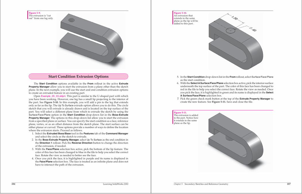
Open Example_05_03.sldprt. This part is similar to the U-shaped part with whichyou have been working. However, one leg has a small lip projecting to the interior ofthe part. See Figure 5-10. In this example, you will add a pin to the leg that extendsonly as far as the lip. The Up To Surface extrude option allows you to do this. The circlesketch that you will extrude is already drawn and is located on the top surface of thepart. You will select a different plane from which to extrude the sketch by using theSurface/Face/Plane option in the Start Condition drop-down list in the Boss-Extrude Property Manager. The options in this drop-down list allow you to start the extrusionfrom a specified plane or surface. You can specify the start condition as a face, referenceplane, vertex, or as an offset distance from the sketch plane. The start surface can beeither planar or curved. These options provide a number of ways to define the locationwhere the extrusion starts. Proceed as follows.
1. Select the Extruded Boss/Base tool in the Features tab of the Command Managerand select the circle as the sketch to extrude.
2. In the Boss-Extrude Property Manager, select Up To Surface as the end condition inthe Direction 1 rollout. Pick the Reverse Direction button to change the directionof the extrusion, if needed.
3. With the Face/Plane selection box active, pick the bottom of the lip feature. Thecolor of this face has been changed to blue in the file to help you select the correctface. Rotate the view as needed to better see the face.
4. Once you pick the face, it is highlighted in purple and its name is displayed inthe Face/Plane selection box. The face is treated as an infinite plane and does nothave to intersect the path of the extrusion.
Figure 5-9.The extrusion is “cutout” from one leg only.
Chapter 5 Secondary Sketches and Reference Geometry 107
5. In the Start Condition drop-down list in the From rollout, select Surface/Face/Planeas the start condition.
6. With the Select A Surface/Face/Plane selection box active, pick the interior surfaceunderneath the top surface of the part. The color of this face has been changed tored in the file to help you select the correct face. Rotate the view as needed. Onceyou pick the face, it is highlighted in green and its name is displayed in the Select A Surface/Face/Plane selection box.
7. Pick the green check mark button at the top of the Extrude Property Manager tocreate the new feature. See Figure 5-11. Save and close the file.
Figure 5-10.An extrusion thatextends to the sameplane as the lip will beadded to this part.
Figure 5-11.The extrusion is addedto the part. Notice howit extends to the sameplane as the lip.
108 Learning SolidWorks 2010
PRACTICE 5-1Complete the practice problem on the student Web site.www.g-wlearning.com/CAD
Converting Geometry and Projecting It to the Sketch Plane
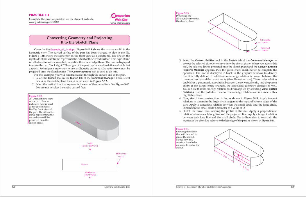
Open the fi le Example_05_04.sldprt. Figure 5-12A shows the part as a solid in the isometric view. The curved surface of the part has been changed to blue in the fi le. Figure 5-12B shows the same part in the front view as a wireframe. The line on the right side of the wireframe represents the extent of the curved surface. This type of line is called a silhouette curve, but, in reality, there is no edge there. The line is displayed to make the part “look right.” The edges of the part can be used to defi ne a sketch, but a special technique is necessary to use a silhouette curve. A silhouette curve must be projected onto the sketch plane. The Convert Entities tool is used to do this.
For this example, you will construct a slot through the curved end of the part. 1. Select the Sketch tool in the Sketch tab of the Command Manager. Then, select
face A as the sketch plane. Face A is indicated in Figure 5-12. 2. Select the vertical line that represents the end of the curved face. See Figure 5-13.
Be sure not to select the entire curved face.
Figure 5-12.A—An isometric view of the part. Face A indicated here is used as the sketch plane. B—The front view of the part. The silhouette curve representing the curved face will be projected onto the sketch plane. Face A
Silhouettecurve
Face A
Wireframe(Front View)
Solid(Isometric View)
A
B
www.g-wlearning.com
ompanionWeb Site
Chapter 5 Secondary Sketches and Reference Geometry 109
3. Select the Convert Entities tool in the Sketch tab of the Command Manager toproject the selected silhouette curve onto the sketch plane. When you access thistool, the selected line is projected onto the sketch plane and the Convert Entities Property Manager appears. Pick the green check mark button to complete theoperation. The line is displayed in black in the graphics window to identifythat it is fully defined. In addition, an on edge relation is created between theconverted entity and the parent entity (the silhouette curve). The on edge relationestablishes a parametric association between the converted entity and the parententity. If the parent entity changes, the associated geometry changes as well.You can see that the on edge relation has been applied by selecting View>Sketch Relations from the pull-down menu. The on edge relation icon is a cube with ahighlighted face.
4. Now, sketch two construction circles, as shown in Figure 5-14. Apply tangentrelations to constrain the large circle tangent to the top and bottom edges of thepart. Apply a concentric relation between the small circle and the large circle.Dimension the small circle’s diameter to a value of .2 .
5. Sketch the three lines forming the profile of the slot. Apply a perpendicularrelation between each long line and the projected line. Apply a tangent relationbetween each long line and the small circle. Use a dimension to constrain thelocation of the short line relative to the left edge of the part, as shown in Figure 5-14.
Figure 5-13.Projecting thesilhouette curve ontothe sketch plane.
Silhouettecurve
Projectedcurve
Figure 5-14.Drawing the sketchthat will be used tocreate the cutout.Notice how twoconstruction circlesare used to center thecutout.
110 Learning SolidWorks 2010
6. Select the Extruded Cut tool in the Features tab of the Command Manager. Usingthe Selected Contours selection box in the Selected Contours rollout, select oneof the edges defining the rectangular area formed by the projected line and thethree lines you just constructed. As an alternative, you can select the two internalareas within the rectangular boundary to create the intended slot.
7. Select Through All as the end condition in the Direction 1 rollout of the Cut-Extrude Property Manager. Then, pick the green check mark button to extrude the sketchand remove its volume from the part. See Figure 5-15. Save and close the file.
Offsetting Geometry in Sketches
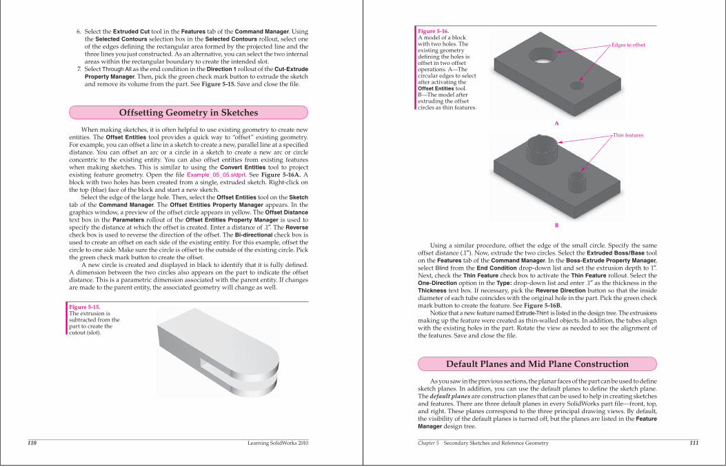
When making sketches, it is often helpful to use existing geometry to create newentities. The Offset Entities tool provides a quick way to “offset” existing geometry.For example, you can offset a line in a sketch to create a new, parallel line at a specifieddistance. You can offset an arc or a circle in a sketch to create a new arc or circleconcentric to the existing entity. You can also offset entities from existing featureswhen making sketches. This is similar to using the Convert Entities tool to projectexisting feature geometry. Open the file Example_05_05.sldprt. See Figure 5-16A. Ablock with two holes has been created from a single, extruded sketch. Right-click onthe top (blue) face of the block and start a new sketch.
Select the edge of the large hole. Then, select the Offset Entities tool on the Sketchtab of the Command Manager. The Offset Entities Property Manager appears. In thegraphics window, a preview of the offset circle appears in yellow. The Offset Distancetext box in the Parameters rollout of the Offset Entities Property Manager is used tospecify the distance at which the offset is created. Enter a distance of .1 . The Reversecheck box is used to reverse the direction of the offset. The Bi-directional check box isused to create an offset on each side of the existing entity. For this example, offset thecircle to one side. Make sure the circle is offset to the outside of the existing circle. Pickthe green check mark button to create the offset.
A new circle is created and displayed in black to identify that it is fully defined.A dimension between the two circles also appears on the part to indicate the offsetdistance. This is a parametric dimension associated with the parent entity. If changesare made to the parent entity, the associated geometry will change as well.
Figure 5-15.The extrusion issubtracted from thepart to create thecutout (slot).
Chapter 5 Secondary Sketches and Reference Geometry 111
Using a similar procedure, offset the edge of the small circle. Specify the sameoffset distance (.1 ). Now, extrude the two circles. Select the Extruded Boss/Base toolon the Features tab of the Command Manager. In the Boss-Extrude Property Manager,select Blind from the End Condition drop-down list and set the extrusion depth to 1 .Next, check the Thin Feature check box to activate the Thin Feature rollout. Select theOne-Direction option in the Type: drop-down list and enter .1 as the thickness in theThickness text box. If necessary, pick the Reverse Direction button so that the insidediameter of each tube coincides with the original hole in the part. Pick the green checkmark button to create the feature. See Figure 5-16B.
Notice that a new feature named Extrude-Thin1 is listed in the design tree. The extrusionsmaking up the feature were created as thin-walled objects. In addition, the tubes alignwith the existing holes in the part. Rotate the view as needed to see the alignment ofthe features. Save and close the file.
Default Planes and Mid Plane Construction
As you saw in the previous sections, the planar faces of the part can be used to definesketch planes. In addition, you can use the default planes to define the sketch plane.The default planes are construction planes that can be used to help in creating sketchesand features. There are three default planes in every SolidWorks part file—front, top,and right. These planes correspond to the three principal drawing views. By default,the visibility of the default planes is turned off, but the planes are listed in the Feature Manager design tree.
Figure 5-16.A model of a blockwith two holes. Theexisting geometrydefining the holes isoffset in two offsetoperations. A—Thecircular edges to selectafter activating theOffset Entities tool.B—The model afterextruding the offsetcircles as thin features.
B
A
Edges to offset
Thin features
112 Learning SolidWorks 2010
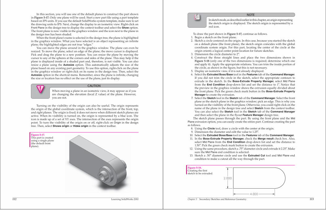
In this section, you will use one of the default planes to construct the part shown in Figure 5-17. Only one plane will be used. Start a new part fi le using a part template based on IPS units. If you use the default SolidWorks system template, make sure to set the drawing units to IPS. Next, change the display to an isometric view. Right-click on Front Plane in the design tree to display the context toolbar and select the Show option. The front plane is now visible in the graphics window and the icon next to the plane in the design tree has been shaded.
When the front plane’s name is selected in the design tree, the plane is highlighted in the graphics window. What you have selected is an object representing an infi nite plane; the highlighted edges are not true “edges.”
You can move the plane around in the graphics window. The plane can even be resized. To move the plane, select an edge of the plane; the move cursor is displayed. Pick and drag the plane to a new position. You can resize the plane by moving the cursor to any of the spheres at the corners and sides of the plane. This may help if the plane is displayed inside of a shaded part and, therefore, is not visible. You can also resize a plane using the Autosize option. This automatically adjusts the size of the plane based on any existing part geometry. To use this option, right-click on the plane in the graphics window or right-click on its name in the design tree. Then, select the Autosize option in the shortcut menu. Remember, since the plane is infi nite, changing the size or location has no effect on the use of the plane, just its display.
CAUTION
When moving a plane in an isometric view, it may appear as if you are changing the elevation (local Z value) of the plane. However, you are not.
Turning on the visibility of the origin can also be useful. The origin represents the origin of the global coordinate system, which is the intersection of the front, top, and right planes. The origin is fi xed; it does not move when different sketch planes are active. When its visibility is turned on, the origin is represented by a blue icon. The icon is made up of a set of XY axes. The intersection of the axes represents the origin point. To turn the visibility of the origin on or off, right-click on Origin in the design tree. Then, select Shows origin or Hides origin in the context toolbar.
Figure 5-17.This part is created using a single plane (the default front plane).
Ands jspois a thspo cnb angoxu igcuostues tre poiust piod agousgas on few ousi zougosa eossougsgo.
Chapter 5 Secondary Sketches and Reference Geometry 113
NOTE
In sketch mode, as described earlier in this chapter, an origin representing the sketch origin is displayed. The sketch origin is represented by a red icon.
To draw the part shown in Figure 5-17, continue as follows. 1. Begin a sketch on the front plane. 2. Sketch a circle centered on the origin. In this case, because you started the sketch
on a default plane (the front plane), the sketch origin coincides with the global coordinate system origin. For this part, locating the center of the circle at the origin orients a logical center point location for future sketches.
3. Dimension the circle diameter to 2 . 4. Construct the three straight lines and place the two dimensions shown in
Figure 5-18 (only one of the two dimensions is required; determine which one and apply it). Apply the appropriate relations. You can trim the inside portion of the circle, as shown in the fi gure, but this is not necessary.
5. Display an isometric view, if it is not already displayed. 6. Select the Extruded Boss/Base tool in the Features tab of the Command Manager.
If you did not trim the circle in the sketch, select the appropriate contours to extrude in the sketch. In the Boss-Extrude Property Manager, select Mid Planefrom the End Condition drop-down list and set the distance to 1 . Notice that the preview in the graphics window shows the extrusion equally divided about the front plane. Pick the green check mark button in the Boss-Extrude Property Manager to create the extrusion.
7. Select the Sketch tool in the Sketch tab of the Command Manager. Select the front plane as the sketch plane in the graphics window; pick an edge. This is why you turned on the visibility of the front plane. Otherwise, you could right-click on the name of the plane in the design tree and select Sketch from the context toolbar. You can also select the Sketch tool in the Sketch tab of the Command Managerand then select the plane in the fl yout Feature Manager design tree.
The sketch plane passes through the part. By using the front plane and the Mid Plane extrusion option, you can easily create the entire part. Continue creating the part as follows. 8. Using the Circle tool, draw a circle with the center at the origin. 9. Dimension the diameter and edit the value to 1.25 . 10. Select the Extruded Boss/Base tool in the Features tab of the Command Manager. 11. In the Boss-Extrude Property Manager, check the Merge result check box. Also,
select Mid Plane from the End Condition drop-down list and set the distance to 1.50 . Pick the green check mark button to create the extrusion.
12. Using the same procedure, sketch a .75 diameter circle and extrude it 2.25 . Make sure the Mid Plane end condition is selected.
13. Sketch a .50 diameter circle and use the Extruded Cut tool and Mid Plane end condition to make a cutout all the way through the part.
Figure 5-18.Creating the fi rst sketch to be extruded.
114 Learning SolidWorks 2010
The part is complete and should look like Figure 5-17. To turn off the visibility of the frontplane, right-click on it in the graphics window or right-click on its name in the designtree. Then, select Hide from the context toolbar. Save the part as Example_05_06.sldprt.
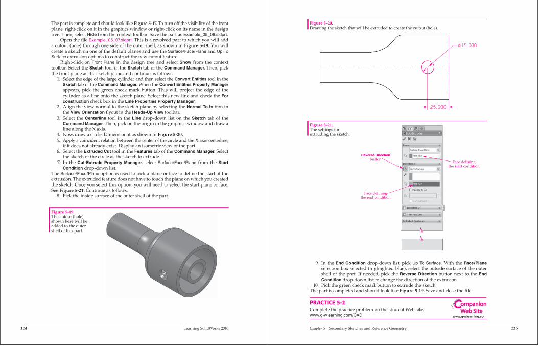
Open the file Example_05_07.sldprt. This is a revolved part to which you will adda cutout (hole) through one side of the outer shell, as shown in Figure 5-19. You willcreate a sketch on one of the default planes and use the Surface/Face/Plane and Up To Surface extrusion options to construct the new cutout feature.
Right-click on Front Plane in the design tree and select Show from the contexttoolbar. Select the Sketch tool in the Sketch tab of the Command Manager. Then, pickthe front plane as the sketch plane and continue as follows.
1. Select the edge of the large cylinder and then select the Convert Entities tool in theSketch tab of the Command Manager. When the Convert Entities Property Managerappears, pick the green check mark button. This will project the edge of thecylinder as a line onto the sketch plane. Select this new line and check the For construction check box in the Line Properties Property Manager.
2. Align the view normal to the sketch plane by selecting the Normal To button inthe View Orientation flyout in the Heads-Up View toolbar.
3. Select the Centerline tool in the Line drop-down list on the Sketch tab of theCommand Manager. Then, pick on the origin in the graphics window and draw aline along the X axis.
4. Now, draw a circle. Dimension it as shown in Figure 5-20.5. Apply a coincident relation between the center of the circle and the X axis centerline,
if it does not already exist. Display an isometric view of the part.6. Select the Extruded Cut tool in the Features tab of the Command Manager. Select
the sketch of the circle as the sketch to extrude.7. In the Cut-Extrude Property Manager, select Surface/Face/Plane from the Start
Condition drop-down list.The Surface/Face/Plane option is used to pick a plane or face to define the start of theextrusion. The extruded feature does not have to touch the plane on which you createdthe sketch. Once you select this option, you will need to select the start plane or face.See Figure 5-21. Continue as follows.
8. Pick the inside surface of the outer shell of the part.
Figure 5-19.The cutout (hole)shown here will beadded to the outershell of this part.
Chapter 5 Secondary Sketches and Reference Geometry 115
9. In the End Condition drop-down list, pick Up To Surface. With the Face/Planeselection box selected (highlighted blue), select the outside surface of the outer shell of the part. If needed, pick the Reverse Direction button next to the End Condition drop-down list to change the direction of the extrusion.
10. Pick the green check mark button to extrude the sketch.The part is completed and should look like Figure 5-19. Save and close the fi le.
PRACTICE 5-2Complete the practice problem on the student Web site.www.g-wlearning.com/CAD
Figure 5-20.Drawing the sketch that will be extruded to create the cutout (hole).
Figure 5-21.The settings for extruding the sketch.
Reverse Directionbutton
Face definingthe end condition
Face definingthe start condition
www.g-wlearning.com
ompanionWeb Site
116 Learning SolidWorks 2010
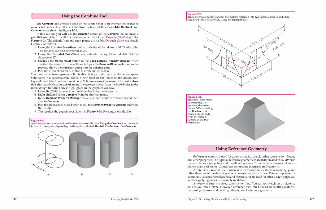
Using the Combine Tool
The Combine tool creates a solid of the volume that is an intersection of two ormore solid bodies. The effects of the three options of this tool—Add, Subtract, andCommon—are shown in Figure 5-22.
In this section, you will use the Common option of the Combine tool to create apart that would be difficult to create any other way. Open Example_05_08.sldprt. SeeFigure 5-23. The default front and right planes are visible. On each plane is a sketch.Continue as follows.
1. Using the Extruded Boss/Base tool, extrude the left-hand sketch 300 to the right.The distance can also be entered as 25.
2. Using the Extruded Boss/Base tool, extrude the right-hand sketch. Set thedistance to 25.
3. Uncheck the Merge result button in the Boss-Extrude Property Manager whencreating the second extrusion. If needed, pick the Reverse Direction button so thepreview shows the extrusion going into the existing part.
4. Pick the green check mark button to create the extrusion.You now have two separate solid bodies that partially occupy the same space.SolidWorks has automatically added a new Solid Bodies folder to the design tree.Expand this folder to see each solid body. SolidWorks uses the name of the last featurethat affected a body as its default name. If you select a body from the Solid Bodies folderin the design tree, the body is highlighted in the graphics window.
5. Using the [Ctrl] key, select both solid bodies from the design tree.6. Right-click and select Combine from the shortcut menu.7. In the Combine Property Manager, make sure both bodies are selected, and then
choose Common.8. Pick the green check mark button to exit the Combine Property Manager and view
the results.9. The result is the pagoda roof shown in Figure 5-24. Save and close the file.
A B C D
Figure 5-22.A—A wireframe representation of two separate solid bodies. Using the Combine tool can resultin one of three parts, depending on the option selected. B—Add. C—Subtract. D—Common.
Chapter 5 Secondary Sketches and Reference Geometry 117
Using Reference Geometry
Reference geometry is used for constructing features, locating construction objects,and other purposes. The types of reference geometry that can be created in SolidWorksinclude planes, axes, points, and coordinate systems. This chapter addresses referenceplanes, axes, and points. Coordinate systems are discussed in Chapter 19.
A reference plane is used when it is necessary to establish a working planeother than one of the default planes or an existing part surface. Reference planes arecommonly used to create sketches and features and are used for other design purposes,such as applying mates in assembly modeling.
A reference axis is a fixed construction line. You cannot sketch on a referenceaxis as you can a plane. However, reference axes can be used in creating features,patterning features, and creating other types of reference geometry.
Figure 5-23.These are two separate sketches that will be extruded into two separate bodies and thencombined into a single body using the Combine tool.
Figure 5-24.This part is the resultof extruding thesketches shown inFigure 5-23 and usingthe Combine tool tocreate a single bodyfrom the sharedvolume of the twoextrusions.
118 Learning SolidWorks 2010
A reference point is a fixed point. Reference points are used in the creation offeatures as well as other types of reference geometry.
You will encounter many uses for reference geometry throughout this book. Thischapter focuses on the use of reference planes and presents related applications forreference axes and points.
Creating Reference PlanesReference planes are used to terminate extrusions, to establish angled and offset
sketch planes, and to constrain assembly components. The latter application is very usefulfor the assembly mates that you will use in assembly modeling later in this text.
SolidWorks makes it easy to create a plane in any orientation by allowing theuser to select up to three references from the existing geometry in a part or assembly.Planes can be constructed by selecting planar or curved surfaces, edges, lines, curves,endpoints, and other reference geometry.
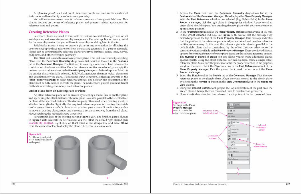
The Plane tool is used to create a reference plane. This tool is activated by selectingPlane from the Reference Geometry drop-down list, which is located in the Featurestab of the Command Manager. The first step in creating a reference plane is to select acombination of reference entities. Once the reference entities are selected, you apply thenecessary constraint options in the Plane Property Manager to define the plane. Based onthe entities that are initially selected, SolidWorks generates the most logical placementand orientation for the plane. If additional input is needed, a message appears in thePlane Property Manager to select reference entities. The position and orientation of theplane must be fully defined to create the plane. The next sections present several differentmethods for creating commonly used reference planes.
Offset Plane from an Existing Face or PlaneAn offset reference plane can be created by selecting a model face or another plane
and specifying the offset distance. The new plane is created parallel to the selected faceor plane at the specified distance. This technique is often used when creating a featureattached to a cylinder. Typically, the required reference plane for creating the sketchcan be created from a default plane or an existing part surface. Since it is impossibleto move an existing plane, a new one is created a set distance away from the old plane.Now, sketching the required shape is possible.
For example, look at the existing part in Figure 5-25A. The finished part is shownin Figure 5-25B. To create the new feature, you will offset the default right plane. OpenExample_05_09.sldprt. Right-click on Right Plane in the design tree and select Showfrom the context toolbar to display the plane. Then, continue as follows.
Figure 5-25.A—The original part.B—A feature is addedto the part.
A B
Chapter 5 Secondary Sketches and Reference Geometry 119
1. Access the Plane tool from the Reference Geometry drop-down list in theFeatures tab of the Command Manager. This displays the Plane Property Manager.With the First Reference selection box selected (highlighted blue) in the Plane Property Manager, pick the right plane in the graphics window. A preview of anoffset plane should appear. You can drag the new plane with your mouse into anapproximate position.
2. In the First Reference rollout of the Plane Property Manager, enter a value of 100 mmin the Offset Distance text box. See Figure 5-26. Notice that the message Fully defined appears at the top of the Plane Property Manager. This message indicatesthat the position of the reference plane is fully constrained and no other referenceentities are necessary. In this case, the reference plane is oriented parallel to thedefault right plane and is constrained by the offset distance. Also notice theconstraint options available in the Plane Property Manager. These provide additionaloptions for creating the new reference plane based on the selected reference entities.The Number of planes to create text box allows you to create additional planesspaced equally using the offset distance. For this example, create a single offsetreference plane. Makesure the plane is offset in the proper direction in the graphicswindow. If needed, check the Flip check box in the First Reference rollout of thePlane Property Manager. Pick the green check mark button to exit the Plane Property Manager.
3. Select the Sketch tool in the Sketch tab of the Command Manager. Pick the newreference plane as the sketch plane. Align the view normal to the sketch planeby selecting the Normal To button in the View Orientation flyout in the Heads-Up View toolbar.
4. Using the Convert Entities tool, project the top and bottom of the part onto thesketch plane. Change the two converted lines to construction geometry.
5. Draw a vertical construction line between the midpoints of the two projected lines.
Figure 5-26.Settings in the Plane Property Managerused to create theoffset reference plane.
Selectedreference
entity
Enter theoffset distance
Constraintoptions
Reference planeis fully defined
120 Learning SolidWorks 2010
6. Draw a circle. Dimension the diameter and edit the value to 35 mm.7. Apply a coincident relation between the center of the circle and the construction
line you drew in step 5.8. Add a dimension between the projected top edge and the center of the circle. Edit
the dimension to a value of 40 mm. See Figure 5-27. Display an isometric view.9. Select the Extruded Boss/Base tool in the Features tab of the Command Manager.
10. Select the circle as the sketch to extrude.11. In the Boss-Extrude Property Manager, check the Merge result check box and select
Up To Surface as the end condition. Then, with the Face/Plane selection box selected(highlighted blue), pick the outside surface of the cylinder.
12. Pick the green check mark button in the Boss-Extrude Property Manager to createthe extrusion. The new feature is added to the part. Save and close the file.
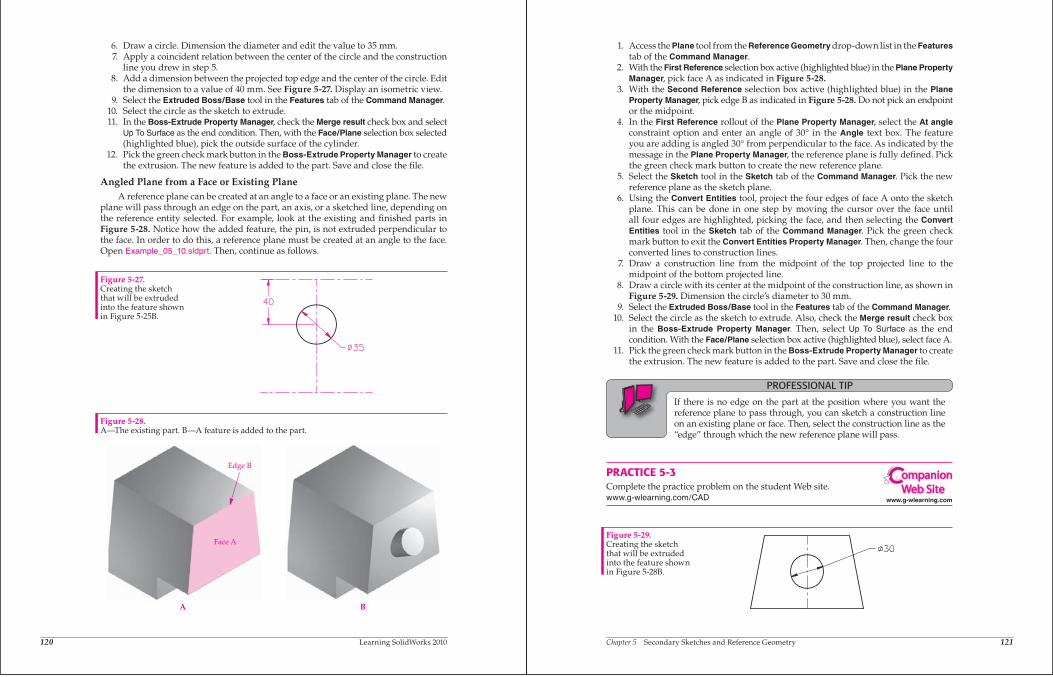
Angled Plane from a Face or Existing PlaneA reference plane can be created at an angle to a face or an existing plane. The new
plane will pass through an edge on the part, an axis, or a sketched line, depending onthe reference entity selected. For example, look at the existing and finished parts inFigure 5-28. Notice how the added feature, the pin, is not extruded perpendicular tothe face. In order to do this, a reference plane must be created at an angle to the face.Open Example_05_10.sldprt. Then, continue as follows.
Figure 5-27.Creating the sketchthat will be extrudedinto the feature shownin Figure 5-25B.
Edge B
Face A
A B
Figure 5-28.A—The existing part. B—A feature is added to the part.
Chapter 5 Secondary Sketches and Reference Geometry 121
1. Access the Plane tool from the Reference Geometry drop-down list in the Features tab of the Command Manager.
2. With the First Reference selection box active (highlighted blue) in the Plane Property Manager, pick face A as indicated in Figure 5-28.
3. With the Second Reference selection box active (highlighted blue) in the Plane Property Manager, pick edge B as indicated in Figure 5-28. Do not pick an endpoint or the midpoint.
4. In the First Reference rollout of the Plane Property Manager, select the At angleconstraint option and enter an angle of 30 in the Angle text box. The feature you are adding is angled 30 from perpendicular to the face. As indicated by the message in the Plane Property Manager, the reference plane is fully defi ned. Pick the green check mark button to create the new reference plane.
5. Select the Sketch tool in the Sketch tab of the Command Manager. Pick the new reference plane as the sketch plane.
6. Using the Convert Entities tool, project the four edges of face A onto the sketch plane. This can be done in one step by moving the cursor over the face until all four edges are highlighted, picking the face, and then selecting the Convert Entities tool in the Sketch tab of the Command Manager. Pick the green check mark button to exit the Convert Entities Property Manager. Then, change the four converted lines to construction lines.
7. Draw a construction line from the midpoint of the top projected line to the midpoint of the bottom projected line.
8. Draw a circle with its center at the midpoint of the construction line, as shown in Figure 5-29. Dimension the circle’s diameter to 30 mm.
9. Select the Extruded Boss/Base tool in the Features tab of the Command Manager. 10. Select the circle as the sketch to extrude. Also, check the Merge result check box
in the Boss-Extrude Property Manager. Then, select Up To Surface as the end condition. With the Face/Plane selection box active (highlighted blue), select face A.
11. Pick the green check mark button in the Boss-Extrude Property Manager to create the extrusion. The new feature is added to the part. Save and close the fi le.
PROFESSIONAL TIP
If there is no edge on the part at the position where you want the reference plane to pass through, you can sketch a construction line on an existing plane or face. Then, select the construction line as the “edge” through which the new reference plane will pass.
PRACTICE 5-3Complete the practice problem on the student Web site.www.g-wlearning.com/CAD
Figure 5-29.Creating the sketch that will be extruded into the feature shown in Figure 5-28B.
www.g-wlearning.com
ompanionWeb Site
122 Learning SolidWorks 2010
Plane through Lines/PointsYou can also select three points, or a combination of lines and points, as reference
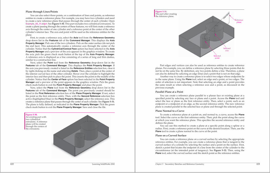
entities to create a reference plane. For example, you may have two cylinders and needto create a new reference plane that passes through the center of each cylinder. OpenExample_05_11.sldprt. See Figure 5-30. This part includes two cylindrical extrusions. Tocreate a plane passing through the centers of these features, we will first create a referenceaxis through the center of one cylinder and a reference point at the center of the othercylinder’s interior face. The axis and point will be used as the reference entities for theplane.
First, to create a reference axis, select the Axis tool from the Reference Geometrydrop-down list in the Features tab of the Command Manager. This displays the Axis Property Manager. Pick one of the two cylinders. Pick on the outer surface (do not pickthe end face). This automatically creates a reference axis through the center of thecylinder. Notice that the Cylindrical/Conical Face option has been selected in the Axis Property Manager and a preview of the axis appears in the graphics window. To createthe axis, pick the green check mark button at the top of the Axis Property Manager.A reference axis is displayed as a line consisting of a series of long and thin dashes,similar to a construction line.
Next, select the Point tool from the Reference Geometry drop-down list in theFeatures tab of the Command Manager. This displays the Point Property Manager. Ifthe axis you previously created is listed in the Reference Entities selection box, clear itby right-clicking on the name and selecting Delete. Then, place a point at the center ofthe interior curved face of the other cylinder. Hover over the cylinder to highlight theinterior face and then pick to place the point. This inserts the point in the middle of thecylinder. Notice that the Center of Face option has been selected in the Point Property Manager and a preview of the point appears in the graphics window. Pick the greencheck mark button to exit the Point Property Manager and place the point.
Now, select the Plane tool from the Reference Geometry drop-down list in theFeatures tab of the Command Manager. The point you previously created should belisted in the First Reference selection box of the Plane Property Manager. If not, selectthe point as the first reference entity. Then, with the Second Reference selection boxactive (highlighted blue) in the Plane Property Manager, select the reference axis. Thiscreates a reference plane that passes through the center of each cylinder. See Figure 5-31.The plane is fully defined, as indicated in the Plane Property Manager. Pick the greencheck mark button to exit the Plane Property Manager. Save and close the file.
Figure 5-30.An existing part withtwo cylindricalextrusions. A referenceplane will be createdthrough the centers ofthe extrusions.
Chapter 5 Secondary Sketches and Reference Geometry 123
Part edges and vertices can also be used as reference entities to create referenceplanes. For example, you can define a reference plane by selecting three points that donot lie on the same line. By definition, any two points define a line. Therefore, a planecan also be defined by selecting an edge (line) and a point that is not on that edge.
Another way to create a reference plane is to select two edges whose endpoints liein the same plane. Using the Plane tool, select an edge and a point, or two edges. Theorder of selection is not important. Note that selecting an edge and a point providesthe same result as when selecting a reference axis and a point, as discussed in theprevious example.
Parallel Plane at a PointYou can create a reference plane parallel to a planar face or existing plane at a
specified point by selecting any face or plane and a point. Access the Plane tool andselect the face or plane as the first reference entity. Then, select a point, such as anendpoint or a midpoint of an edge, as the second reference entity. The new referenceplane is created parallel to the selected face or plane and through the selected point.
Plane Normal to a CurveTo create a reference plane at a point on, and normal to, a curve, access the Plane
tool. Select the curve as the first reference entity. Then, pick the point along the curveat which you want the reference plane. This specifies the second reference entity anddefines the plane.
You can use this method to create a plane at a specific point along a spline or aradius. First, create a reference point on the curve at the desired location. Then, use thePlane tool to create a plane normal to the curve at the point.
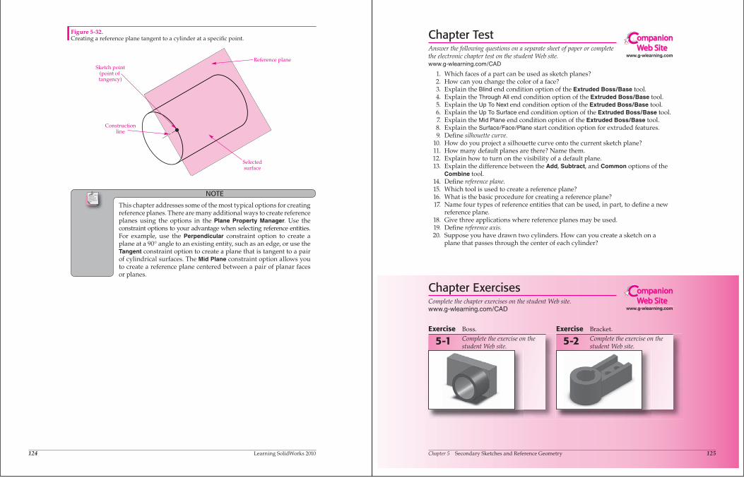
Plane on a Curved SurfaceYou can create a reference plane on a curved surface by selecting the appropriate
reference entities. For example, you can create a reference plane that is tangent to thecurved surface of a cylinder by selecting the surface and a point on the surface. First,sketch a point that locates the endpoint of a line from the center of the cylinder to thecircumference (at the intended point of tangency). See Figure 5-32. Then, using thePlane tool, select the curved surface and the sketch point as the reference entities.
Figure 5-31.The part after creatingthe reference plane.
Referenceplane
Selectedaxis
Selectedpoint
Ands jspois a thspo cnb angoxu igcuostues tre poiust piod agousgas on few ousi zougosa eossougsgo.
124 Learning SolidWorks 2010
NOTE
This chapter addresses some of the most typical options for creating reference planes. There are many additional ways to create reference planes using the options in the Plane Property Manager. Use the constraint options to your advantage when selecting reference entities. For example, use the Perpendicular constraint option to create a plane at a 90 angle to an existing entity, such as an edge, or use the Tangent constraint option to create a plane that is tangent to a pair of cylindrical surfaces. The Mid Plane constraint option allows you to create a reference plane centered between a pair of planar faces or planes.
Sketch point(point of tangency)
Constructionline
Reference plane
Selectedsurface
Figure 5-32.Creating a reference plane tangent to a cylinder at a specifi c point.
Chapter 5 Secondary Sketches and Reference Geometry 125
Chapter TestAnswer the following questions on a separate sheet of paper or complete the electronic chapter test on the student Web site.www.g-wlearning.com/CAD
1. Which faces of a part can be used as sketch planes? 2. How can you change the color of a face? 3. Explain the Blind end condition option of the Extruded Boss/Base tool. 4. Explain the Through All end condition option of the Extruded Boss/Base tool. 5. Explain the Up To Next end condition option of the Extruded Boss/Base tool. 6. Explain the Up To Surface end condition option of the Extruded Boss/Base tool. 7. Explain the Mid Plane end condition option of the Extruded Boss/Base tool. 8. Explain the Surface/Face/Plane start condition option for extruded features. 9. Defi ne silhouette curve. 10. How do you project a silhouette curve onto the current sketch plane? 11. How many default planes are there? Name them. 12. Explain how to turn on the visibility of a default plane. 13. Explain the difference between the Add, Subtract, and Common options of the
Combine tool. 14. Defi ne reference plane. 15. Which tool is used to create a reference plane? 16. What is the basic procedure for creating a reference plane? 17. Name four types of reference entities that can be used, in part, to defi ne a new
reference plane. 18. Give three applications where reference planes may be used. 19. Defi ne reference axis. 20. Suppose you have drawn two cylinders. How can you create a sketch on a
plane that passes through the center of each cylinder?
Exercise Boss.Complete the exercise on the student Web site.
5-1Exercise Bracket.
Complete the exercise on the student Web site.
5-2
www.g-wlearning.com
ompanionWeb Site
Chapter ExercisesComplete the chapter exercises on the student Web site.www.g-wlearning.com/CAD www.g-wlearning.com
ompanionWeb Site
126 Learning SolidWorks 2010
Exercise Cutouts.Complete the exercise on the student Web site.
5-3Exercise Angled Part.
Complete the exercise on the student Web site.
5-4
Exercise Combined Bodies.Complete the exercise on the student Web site.
5-5Exercise Cylinder with Inlet.
Complete the exercise on the student Web site.
5-6
Exercise Center Cutouts.Complete the exercise on the student Web site.
5-7Exercise Yoke.
Complete the exercise on the student Web site.
5-8
Exercise Brace.Complete the exercise on the student Web site.
5-9


