9th Annual Sucker Rod Pumping
Workshop
Renaissance Hotel
Oklahoma City, Oklahoma
September 17 - 20, 2013
Gas Locked Pumps are NOT Gas Locked!
Lynn Rowlan
Ken Skinner
Echometer Company
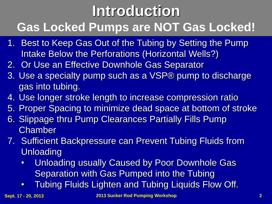
1. Best to Keep Gas Out of the Tubing by Setting the Pump
Intake Below the Perforations (Horizontal Wells?)
2. Or Use an Effective Downhole Gas Separator
3. Use a specialty pump such as a VSP® pump to discharge
gas into tubing.
4. Use longer stroke length to increase compression ratio
5. Proper Spacing to minimize dead space at bottom of stroke
6. Slippage thru Pump Clearances Partially Fills Pump
Chamber
7. Sufficient Backpressure can Prevent Tubing Fluids from
Unloading
• Unloading usually Caused by Poor Downhole Gas
Separation with Gas Pumped into the Tubing
• Tubing Fluids Lighten and Tubing Liquids Flow Off.
Introduction Gas Locked Pumps are NOT Gas Locked!
Sept. 17 - 20, 2013 2013 Sucker Rod Pumping Workshop 2

Sept. 17 - 20, 2013 2013 Sucker Rod Pumping Workshop 3
What is a Gas Locked Pump
• Both traveling valve, TV, and standing valve,
SV, remain closed during the entire stroke
• Pump is completely filled with gas
• Gas Lock occurs if:
– Downstroke the tubing pressure on top of the plunger is always
greater than the compressed pressure inside pump chamber
– Upstroke the expanding pump chamber pressure is always
greater than the outside wellbore pressure at the pump intake.
• TV and SV open if pressure below the valve is greater
than the pressure above the valve.

Sept. 17 - 20, 2013 2013 Sucker Rod Pumping Workshop 4
Synthetic Pump Card Shape: Gas Locked Pump
Gas Locked Pump...Both valves
remain closed because the
discharge tubing pressure, (Pd), is
greater the pump chamber
pressure, (Pchamber), which is also
greater than the pump intake
pressure, Pint. The compression
ratio of the sucker rod pump is too
small, with the result that neither
valve opens until the clearance
space between valves fills by
slippage of fluids past the plunger,
or the fluid level is allowed to rise
so that a smaller compression ratio
is required to discharge gas from
the pump into the tubing.
Pd > Pchamber > Pint
Pd > Pchamber at
bottom of stroke
Pchamber > Pint
at top of stroke
Zero Load Line FoDn = 0
Fo from Fluid Level

Expansion
Should Open SV Compression
Should Open TV Zero Load Reached Pchamber > PD
Fo reached when Pchamber < Pint
Pint Pint
PD
PD
Sept. 17 - 20, 2013 2013 Sucker Rod Pumping Workshop 5
Vint
VD
PIVI PDVD
Intake (-----) = (------) Discharge
ZI ZD
Iso-thermal
No Change in Rs
Up Stroke
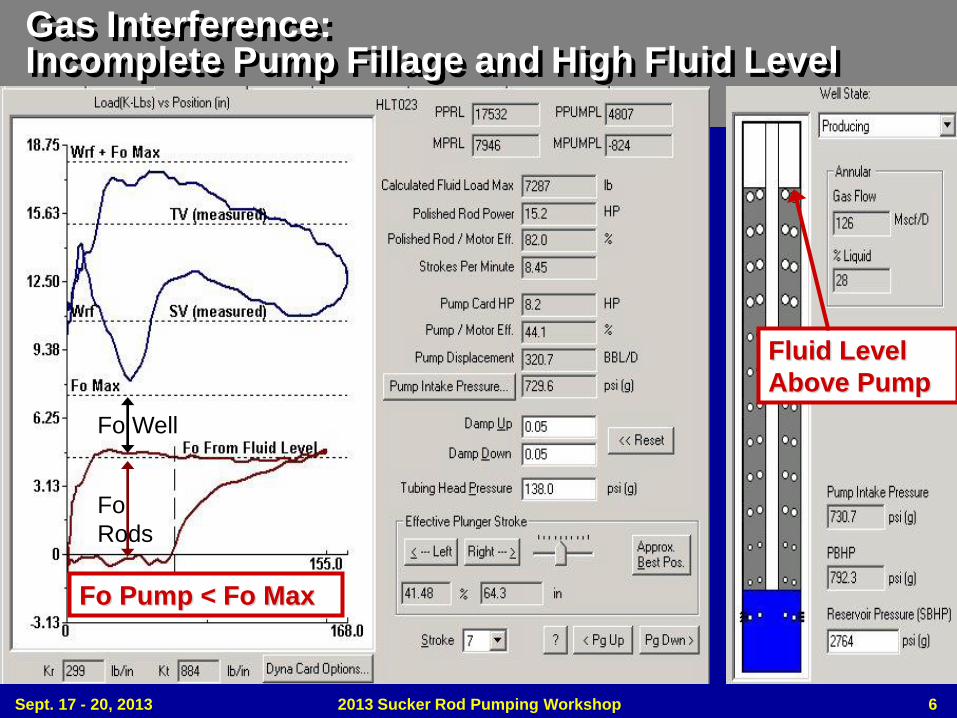
Gas Interference: Incomplete Pump Fillage and High Fluid Level
Fo
Rods
Fo Well
Fluid Level
Above Pump
Fo Pump < Fo Max
Sept. 17 - 20, 2013 2013 Sucker Rod Pumping Workshop 6
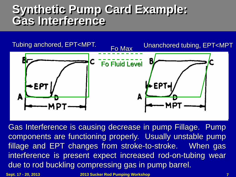
Synthetic Pump Card Example: Gas Interference
Gas Interference is causing decrease in pump Fillage. Pump
components are functioning properly. Usually unstable pump
fillage and EPT changes from stroke-to-stroke. When gas
interference is present expect increased rod-on-tubing wear
due to rod buckling compressing gas in pump barrel.
Tubing anchored, EPT<MPT.
Unanchored tubing, EPT<MPT
Fo Fluid Level
Fo Max
Sept. 17 - 20, 2013 2013 Sucker Rod Pumping Workshop 7
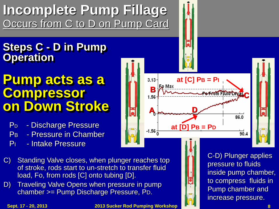
Steps C - D in Pump Operation Pump acts as a Compressor on Down Stroke A
B C
D
Incomplete Pump Fillage Occurs from C to D on Pump Card
C) Standing Valve closes, when plunger reaches top of stroke, rods start to un-stretch to transfer fluid load, Fo, from rods [C] onto tubing [D].
D) Traveling Valve Opens when pressure in pump chamber >= Pump Discharge Pressure, PD.
C-D) Plunger applies
pressure to fluids
inside pump chamber,
to compress fluids in
Pump chamber and
increase pressure.
at [C] PB = PI
at [D] PB = PD PD - Discharge Pressure
PB - Pressure in Chamber
PI - Intake Pressure
Sept. 17 - 20, 2013 2013 Sucker Rod Pumping Workshop 8
2013 Sucker Rod Pumping Workshop
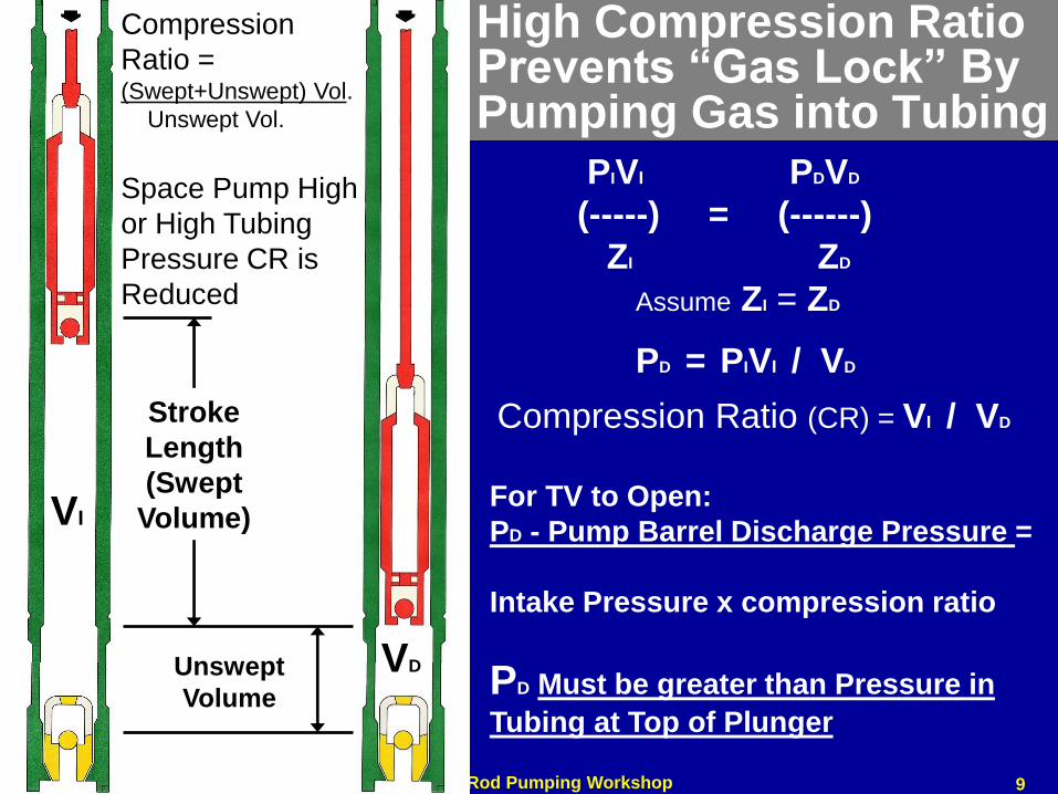
High Compression Ratio Prevents “Gas Lock” By Pumping Gas into Tubing
A
Stroke
Length
(Swept
Volume)
Unswept
Volume
Compression
Ratio = (Swept+Unswept) Vol.
Unswept Vol.
For TV to Open:
PD - Pump Barrel Discharge Pressure =
Intake Pressure x compression ratio
PD Must be greater than Pressure in
Tubing at Top of Plunger
PIVI PDVD
(-----) = (------)
ZI ZD
Assume ZI = ZD
PD = PIVI / VD
Space Pump High
or High Tubing
Pressure CR is
Reduced
Compression Ratio (CR) = VI / VD
VI
VD
9
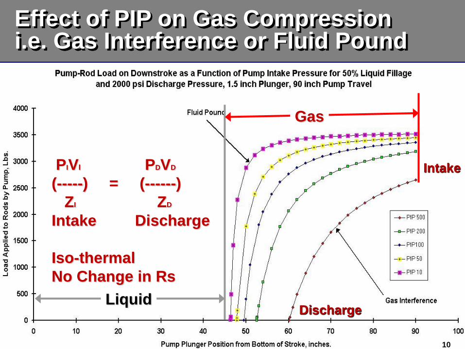
Effect of PIP on Gas Compression i.e. Gas Interference or Fluid Pound
Liquid
Gas
PIVI PDVD
(-----) = (------)
ZI ZD
Intake Discharge
Iso-thermal
No Change in Rs
Intake
Discharge
10
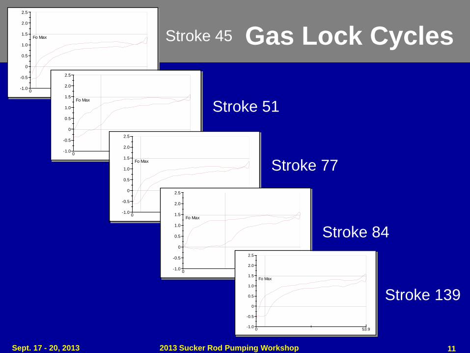
Gas Lock Cycles
0 53.9-1.0
-0.5
0
0.5
1.0
1.5
2.0
2.5
Fo Max Stroke 45
0 53.9-1.0
-0.5
0
0.5
1.0
1.5
2.0
2.5
Fo Max
Stroke 51
0 54.0-1.0
-0.5
0
0.5
1.0
1.5
2.0
2.5
Fo Max
Stroke 77
0 54.3-1.0
-0.5
0
0.5
1.0
1.5
2.0
2.5
Fo Max
Stroke 84
0 53.9-1.0
-0.5
0
0.5
1.0
1.5
2.0
2.5
Fo Max
Stroke 139
Sept. 17 - 20, 2013 2013 Sucker Rod Pumping Workshop 11

“Gas Lock” Occurs, When Both: 1) Point “A” is Above 0 Line 2) Point “C” is Below Fo From the Fluid Level
A
C
Tag
Tag Bad for Equipment, but
Many tag due to “Gas Locking”
Fo From the Fluid Level
2013 Sucker Rod Pumping Workshop 12 Sept. 17 - 20, 2013
NOT GAS LOCKED

Pump Gas Up the Tubing
Gas Locked?
13
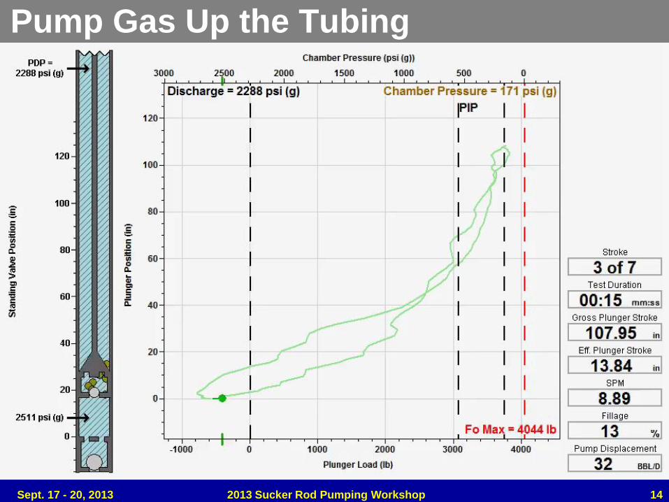
Pump Gas Up the Tubing
Sept. 17 - 20, 2013 2013 Sucker Rod Pumping Workshop 14
2013 Sucker Rod Pumping Workshop Sept. 11 - 14, 2007
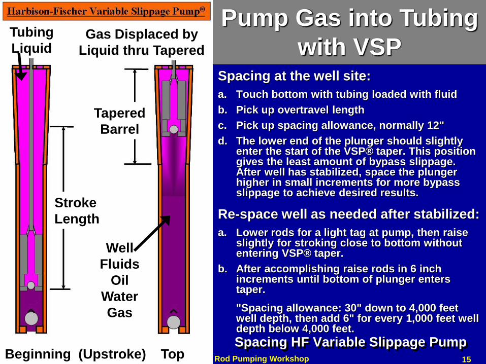
Spacing HF Variable Slippage Pump
Spacing at the well site:
a. Touch bottom with tubing loaded with fluid
b. Pick up overtravel length
c. Pick up spacing allowance, normally 12"
d. The lower end of the plunger should slightly enter the start of the VSP® taper. This position gives the least amount of bypass slippage. After well has stabilized, space the plunger higher in small increments for more bypass slippage to achieve desired results.
Re-space well as needed after stabilized:
a. Lower rods for a light tag at pump, then raise slightly for stroking close to bottom without entering VSP® taper.
b. After accomplishing raise rods in 6 inch increments until bottom of plunger enters taper.
"Spacing allowance: 30" down to 4,000 feet well depth, then add 6" for every 1,000 feet well depth below 4,000 feet.
Stroke
Length
Tapered
Barrel
Beginning (Upstroke) Top
Tubing
Liquid
Well
Fluids
Oil
Water
Gas
Gas Displaced by
Liquid thru Tapered
Pump Gas into Tubing
with VSP
15
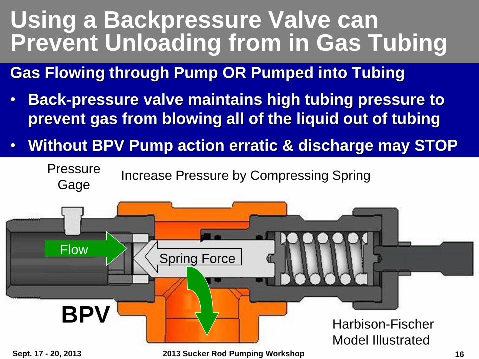
Using a Backpressure Valve can Prevent Unloading from in Gas Tubing Gas Flowing through Pump OR Pumped into Tubing
• Back-pressure valve maintains high tubing pressure to
prevent gas from blowing all of the liquid out of tubing
• Without BPV Pump action erratic & discharge may STOP
Flow
Harbison-Fischer
Model Illustrated
Increase Pressure by Compressing Spring Pressure
Gage
Spring Force
BPV
Sept. 17 - 20, 2013 2013 Sucker Rod Pumping Workshop 16
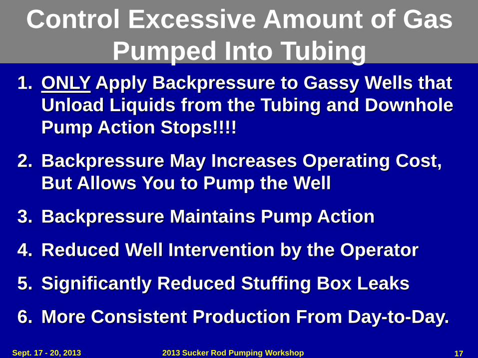
Control Excessive Amount of Gas
Pumped Into Tubing 1. ONLY Apply Backpressure to Gassy Wells that
Unload Liquids from the Tubing and Downhole
Pump Action Stops!!!!
2. Backpressure May Increases Operating Cost,
But Allows You to Pump the Well
3. Backpressure Maintains Pump Action
4. Reduced Well Intervention by the Operator
5. Significantly Reduced Stuffing Box Leaks
6. More Consistent Production From Day-to-Day.
Sept. 17 - 20, 2013 2013 Sucker Rod Pumping Workshop 17
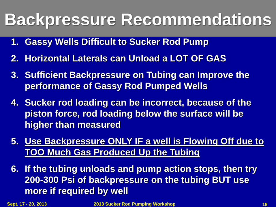
Backpressure Recommendations 1. Gassy Wells Difficult to Sucker Rod Pump
2. Horizontal Laterals can Unload a LOT OF GAS
3. Sufficient Backpressure on Tubing can Improve the
performance of Gassy Rod Pumped Wells
4. Sucker rod loading can be incorrect, because of the
piston force, rod loading below the surface will be
higher than measured
5. Use Backpressure ONLY IF a well is Flowing Off due to
TOO Much Gas Produced Up the Tubing
6. If the tubing unloads and pump action stops, then try
200-300 Psi of backpressure on the tubing BUT use
more if required by well
Sept. 17 - 20, 2013 2013 Sucker Rod Pumping Workshop 18
2013 Sucker Rod Pumping Workshop
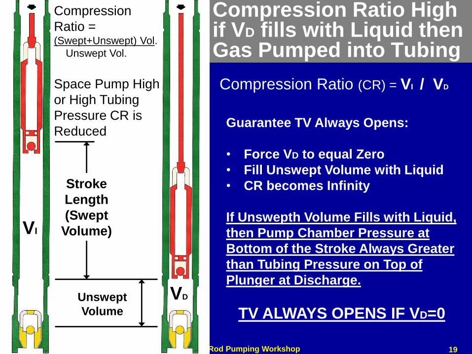
Compression Ratio High if VD fills with Liquid then Gas Pumped into Tubing
A
Stroke
Length
(Swept
Volume)
Unswept
Volume
Compression
Ratio = (Swept+Unswept) Vol.
Unswept Vol.
Guarantee TV Always Opens:
• Force VD to equal Zero
• Fill Unswept Volume with Liquid
• CR becomes Infinity
If Unswepth Volume Fills with Liquid,
then Pump Chamber Pressure at
Bottom of the Stroke Always Greater
than Tubing Pressure on Top of
Plunger at Discharge.
TV ALWAYS OPENS IF VD=0
Space Pump High
or High Tubing
Pressure CR is
Reduced
Compression Ratio (CR) = VI / VD
VI
VD
19
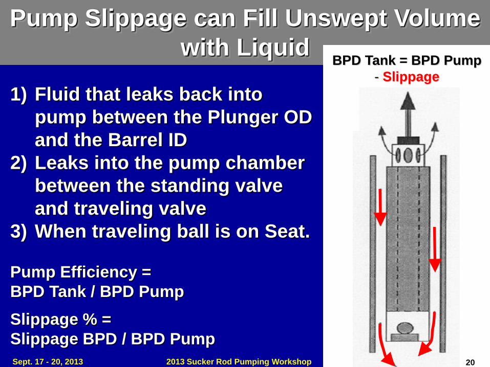
BPD Tank = BPD Pump
- Slippage
Pump Slippage can Fill Unswept Volume
with Liquid
1) Fluid that leaks back into
pump between the Plunger OD
and the Barrel ID
2) Leaks into the pump chamber
between the standing valve
and traveling valve
3) When traveling ball is on Seat.
Pump Efficiency =
BPD Tank / BPD Pump
Slippage % =
Slippage BPD / BPD Pump
Sept. 17 - 20, 2013 2013 Sucker Rod Pumping Workshop 20
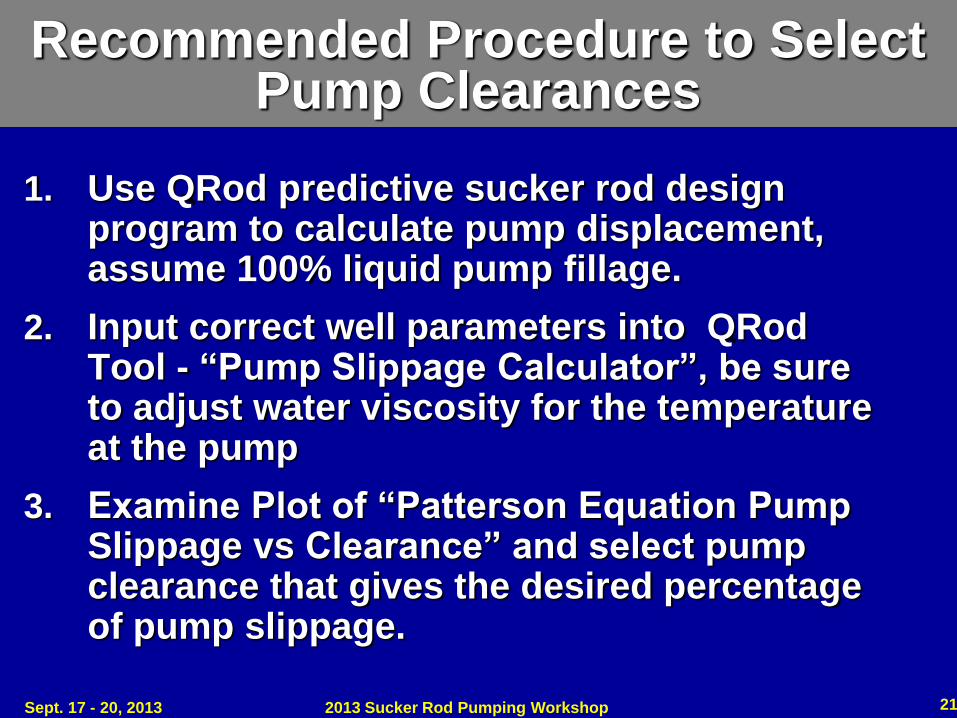
Recommended Procedure to Select Pump Clearances
1. Use QRod predictive sucker rod design program to calculate pump displacement, assume 100% liquid pump fillage.
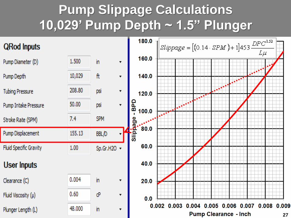
2. Input correct well parameters into QRod Tool - “Pump Slippage Calculator”, be sure to adjust water viscosity for the temperature at the pump
3. Examine Plot of “Patterson Equation Pump Slippage vs Clearance” and select pump clearance that gives the desired percentage of pump slippage.
Sept. 17 - 20, 2013 2013 Sucker Rod Pumping Workshop 21

651 BPD
Sept. 17 - 20, 2013 2013 Sucker Rod Pumping Workshop 22
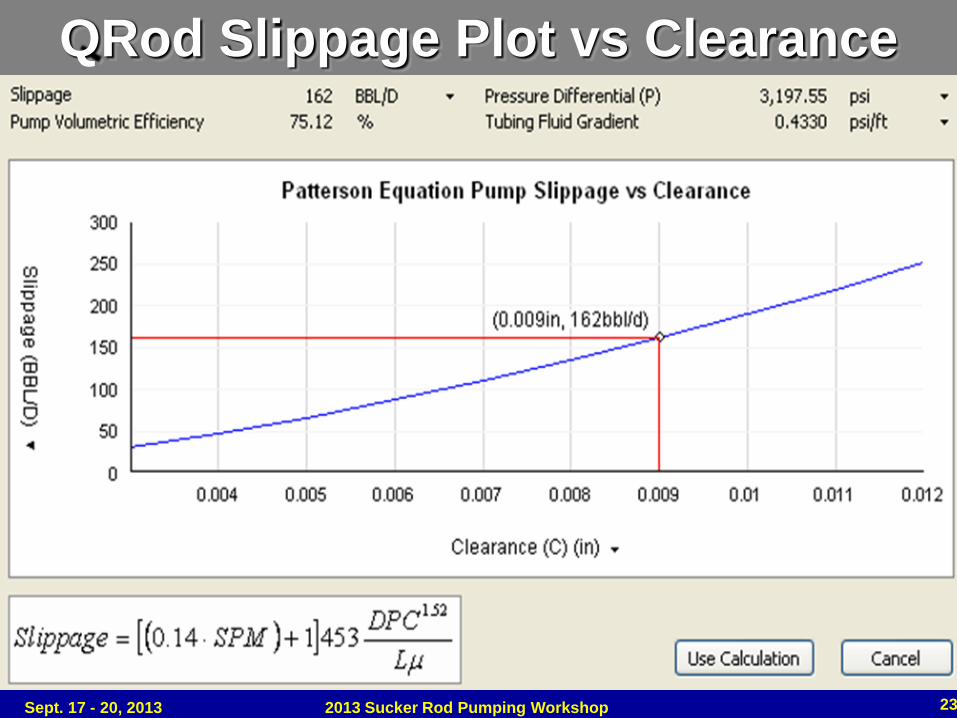
QRod Slippage Plot vs Clearance
Sept. 17 - 20, 2013 2013 Sucker Rod Pumping Workshop 23
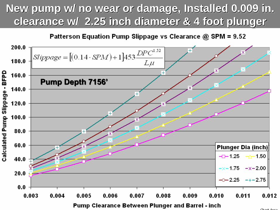
New pump w/ no wear or damage, Installed 0.009 in.
clearance w/ 2.25 inch diameter & 4 foot plunger
Pump Depth 7156’
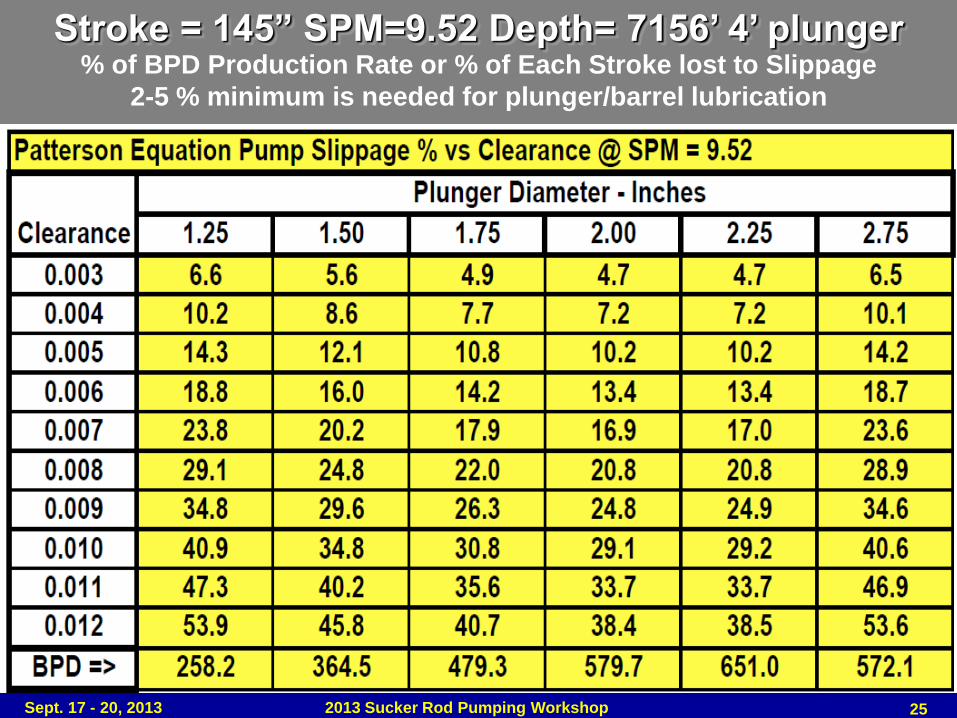
Stroke = 145” SPM=9.52 Depth= 7156’ 4’ plunger % of BPD Production Rate or % of Each Stroke lost to Slippage
2-5 % minimum is needed for plunger/barrel lubrication
Sept. 17 - 20, 2013 2013 Sucker Rod Pumping Workshop 25
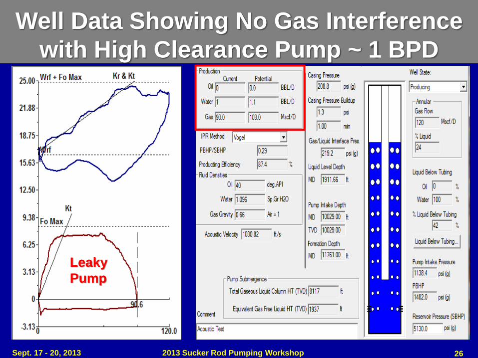
Leaky
Pump
Well Data Showing No Gas Interference
with High Clearance Pump ~ 1 BPD
26 Sept. 17 - 20, 2013 2013 Sucker Rod Pumping Workshop
Leaky
Pump
Pump Slippage Calculations
10,029’ Pump Depth ~ 1.5” Plunger
27
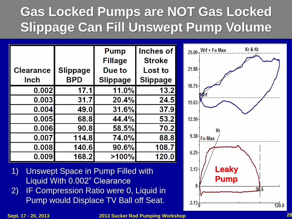
Leaky
Pump 1) Unswept Space in Pump Filled with
Liquid With 0.002” Clearance
2) IF Compression Ratio were 0, Liquid in
Pump would Displace TV Ball off Seat.
Gas Locked Pumps are NOT Gas Locked
Slippage Can Fill Unswept Pump Volume
Sept. 17 - 20, 2013 2013 Sucker Rod Pumping Workshop 28
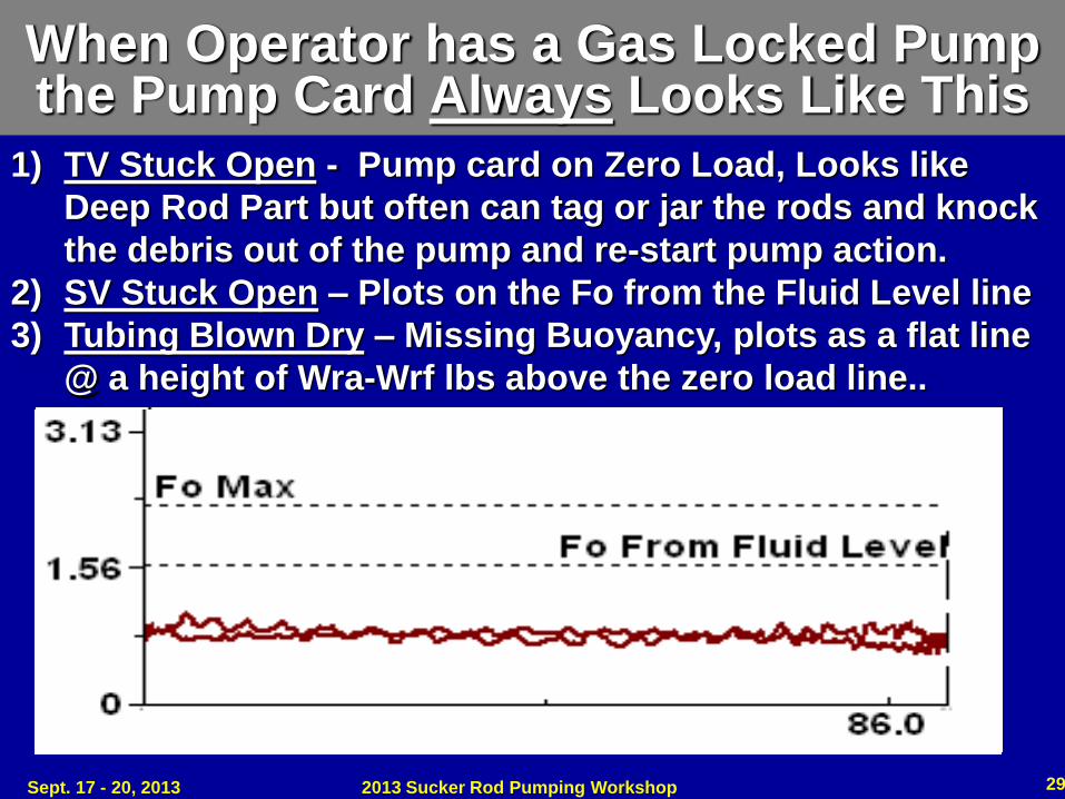
When Operator has a Gas Locked Pump the Pump Card Always Looks Like This
1) TV Stuck Open - Pump card on Zero Load, Looks like
Deep Rod Part but often can tag or jar the rods and knock
the debris out of the pump and re-start pump action.
2) SV Stuck Open – Plots on the Fo from the Fluid Level line
3) Tubing Blown Dry – Missing Buoyancy, plots as a flat line
@ a height of Wra-Wrf lbs above the zero load line..
Sept. 17 - 20, 2013 2013 Sucker Rod Pumping Workshop 29
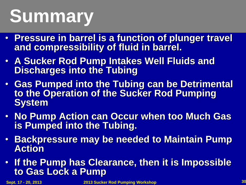
Summary • Pressure in barrel is a function of plunger travel
and compressibility of fluid in barrel.
• A Sucker Rod Pump Intakes Well Fluids and Discharges into the Tubing
• Gas Pumped into the Tubing can be Detrimental to the Operation of the Sucker Rod Pumping System
• No Pump Action can Occur when too Much Gas is Pumped into the Tubing.
• Backpressure may be needed to Maintain Pump Action
• If the Pump has Clearance, then it is Impossible to Gas Lock a Pump
Sept. 17 - 20, 2013 2013 Sucker Rod Pumping Workshop 30
Sept. 17 - 20, 2013 2013 Sucker Rod Pumping Workshop 31
Copyright
Rights to this presentation are owned by the company(ies) and/or author(s) listed on the title page. By submitting this presentation to the Sucker Rod Pumping Workshop, they grant to the Workshop, the Artificial Lift Research and Development Council (ALRDC), and the Southwestern Petroleum Short Course (SWPSC), rights to:
– Display the presentation at the Workshop.
– Place it on the www.alrdc.com web site, with access to the site to be as directed by the Workshop Steering Committee.
– Place it on a CD for distribution and/or sale as directed by the Workshop Steering Committee.
Other use of this presentation is prohibited without the expressed written permission of the author(s). The owner company(ies) and/or author(s) may publish this material in other journals or magazines if they refer to the Sucker Rod Pumping Workshop where it was first presented.
Sept. 17 - 20, 2013 2013 Sucker Rod Pumping Workshop 32
Disclaimer
The following disclaimer shall be included as the last page of a Technical Presentation or Continuing Education Course. A similar disclaimer is included on the front page of the Sucker Rod Pumping Web Site.
The Artificial Lift Research and Development Council and its officers and trustees, and the Sucker Rod Pumping Workshop Steering Committee members, and their supporting organizations and companies (here-in-after referred to as the Sponsoring Organizations), and the author(s) of this Technical Presentation or Continuing Education Training Course and their company(ies), provide this presentation and/or training material at the Sucker Rod Pumping Workshop "as is" without any warranty of any kind, express or implied, as to the accuracy of the information or the products or services referred to by any presenter (in so far as such warranties may be excluded under any relevant law) and these members and their companies will not be liable for unlawful actions and any losses or damage that may result from use of any presentation as a consequence of any inaccuracies in, or any omission from, the information which therein may be contained.
The views, opinions, and conclusions expressed in these presentations and/or training materials are those of the author and not necessarily those of the Sponsoring Organizations. The author is solely responsible for the content of the materials.
The Sponsoring Organizations cannot and do not warrant the accuracy of these documents beyond the source documents, although we do make every attempt to work from authoritative sources. The Sponsoring Organizations provide these presentations and/or training materials as a service. The Sponsoring Organizations make no representations or warranties, express or implied, with respect to the presentations and/or training materials, or any part thereof, including any warrantees of title, non-infringement of copyright or patent rights of others, merchantability, or fitness or suitability for any purpose.


