FW102C
Motorized Filter Wheel
Operating Manual
Motorized Filter Wheel
20242-D02 Rev C, June 17, 2011 Page 2 www.thorlabs.com
Table of Contents
Part 1. Description ...................................................................................................................................4
Part 2. Basic Operation ............................................................................................................................6 2.1. Changing and Removing Filters ............................................................................................................. 6
2.2. Mounting ................................................................................................................................................... 6
2.3. Power ......................................................................................................................................................... 6
2.4. Aperture .................................................................................................................................................... 7
2.5. Manual Control ........................................................................................................................................ 7
2.6. External Trigger ....................................................................................................................................... 7
Part 3. Software Control ..........................................................................................................................8 3.1. Application Software Operation ............................................................................................................. 8
Establishing Communications with FW102C ............................................................................................................ 8 Programmed Sequence Operation (Scan Mode) ........................................................................................................ 9 Help Menu ................................................................................................................................................................. 9 Minimum PC Requirements ...................................................................................................................................... 9
3.2. Command Line Interface ...................................................................................................................... 10 Keywords (Commands and Queries) ....................................................................................................................... 10
3.3. ActiveX Control ...................................................................................................................................... 11
Part 4. Troubleshooting and Maintenance ...........................................................................................13 Removing Filter Holder ........................................................................................................................................... 13
Part 5. Specifications .............................................................................................................................14 5.1. Performance............................................................................................................................................ 14
5.2. Electrical ................................................................................................................................................. 14
5.3. Physical Characteristics and Interface ................................................................................................. 14
Part 6. Mechanical Drawings ................................................................................................................15
Part 7. Regulatory ..................................................................................................................................16
Part 8. Thorlabs Worldwide Contacts ...................................................................................................17
Motorized Filter Wheel
20242-D02 Rev C, June 17, 2011 Page 3 www.thorlabs.com
Table of Figures Figure 1 Filter Wheel System ............................................................................................................... 5 Figure 2 Filter Wheel Mounting Holes ................................................................................................ 6 Figure 3 Filter Wheel Apertures ........................................................................................................... 7 Figure 4 Software Screen Shot: Initial Startup Screen ......................................................................... 8 Figure 5 Software Screen Shot: Setting the COM Port ........................................................................ 8 Figure 6 Software Screen Shot: Changing the Filter Position.............................................................. 9 Figure 7 Open Filter Wheel ................................................................................................................ 13 Figure 8 Mechanical Drawing ............................................................................................................ 15
Motorized Filter Wheel
20242-D02 Rev C, June 17, 2011 Page 4 www.thorlabs.com
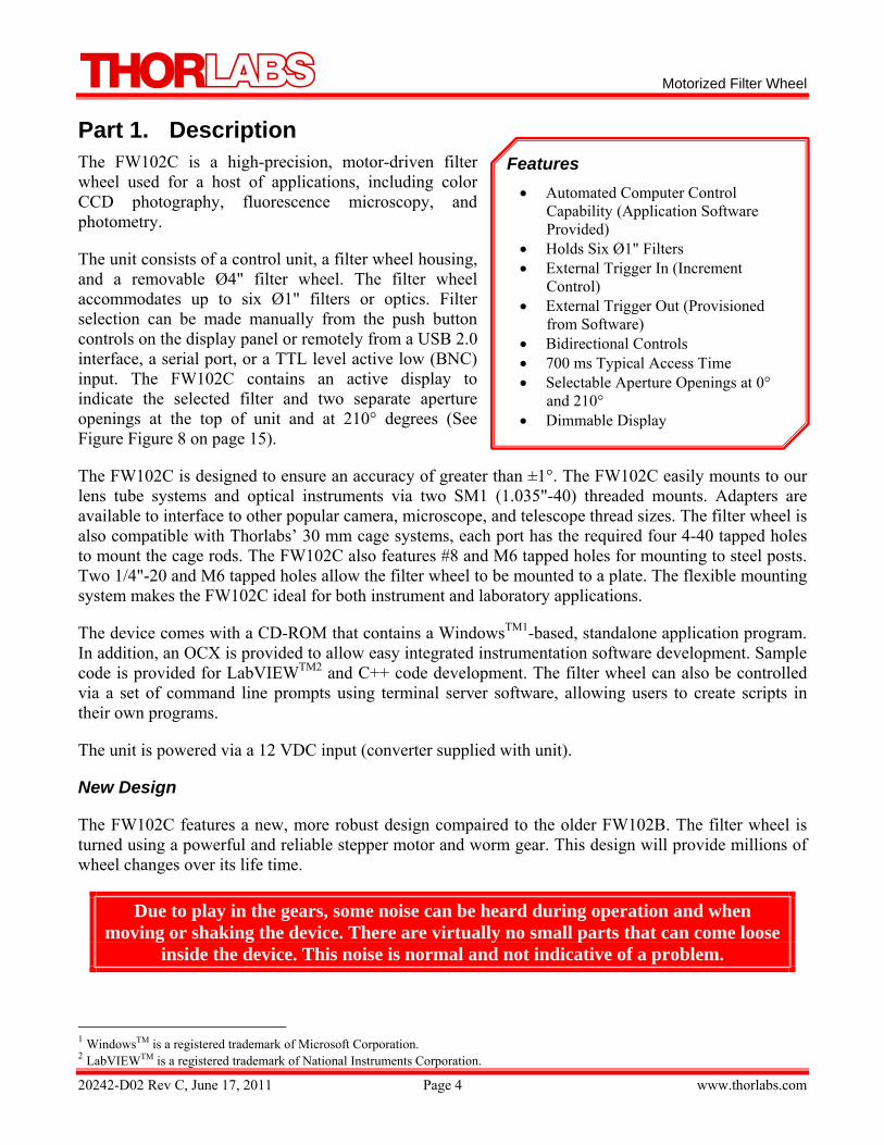
Part 1. Description The FW102C is a high-precision, motor-driven filter wheel used for a host of applications, including color CCD photography, fluorescence microscopy, and photometry.
The unit consists of a control unit, a filter wheel housing, and a removable Ø4" filter wheel. The filter wheel accommodates up to six Ø1" filters or optics. Filter selection can be made manually from the push button controls on the display panel or remotely from a USB 2.0 interface, a serial port, or a TTL level active low (BNC) input. The FW102C contains an active display to indicate the selected filter and two separate aperture openings at the top of unit and at 210° degrees (See Figure Figure 8 on page 15).
The FW102C is designed to ensure an accuracy of greater than ±1°. The FW102C easily mounts to our lens tube systems and optical instruments via two SM1 (1.035"-40) threaded mounts. Adapters are available to interface to other popular camera, microscope, and telescope thread sizes. The filter wheel is also compatible with Thorlabs’ 30 mm cage systems, each port has the required four 4-40 tapped holes to mount the cage rods. The FW102C also features #8 and M6 tapped holes for mounting to steel posts. Two 1/4"-20 and M6 tapped holes allow the filter wheel to be mounted to a plate. The flexible mounting system makes the FW102C ideal for both instrument and laboratory applications.
The device comes with a CD-ROM that contains a WindowsTM1-based, standalone application program. In addition, an OCX is provided to allow easy integrated instrumentation software development. Sample code is provided for LabVIEWTM2 and C++ code development. The filter wheel can also be controlled via a set of command line prompts using terminal server software, allowing users to create scripts in their own programs.
The unit is powered via a 12 VDC input (converter supplied with unit).
New Design
The FW102C features a new, more robust design compaired to the older FW102B. The filter wheel is turned using a powerful and reliable stepper motor and worm gear. This design will provide millions of wheel changes over its life time.
Due to play in the gears, some noise can be heard during operation and when moving or shaking the device. There are virtually no small parts that can come loose
inside the device. This noise is normal and not indicative of a problem.
1 WindowsTM is a registered trademark of Microsoft Corporation. 2 LabVIEWTM is a registered trademark of National Instruments Corporation.
Features • Automated Computer Control
Capability (Application Software Provided)
• Holds Six Ø1" Filters • External Trigger In (Increment
Control) • External Trigger Out (Provisioned
from Software) • Bidirectional Controls • 700 ms Typical Access Time • Selectable Aperture Openings at 0°
and 210° • Dimmable Display
Motorized Filter Wheel
20242-D02 Rev C, June 17, 2011 Page 5 www.thorlabs.com
Shipping Inventory
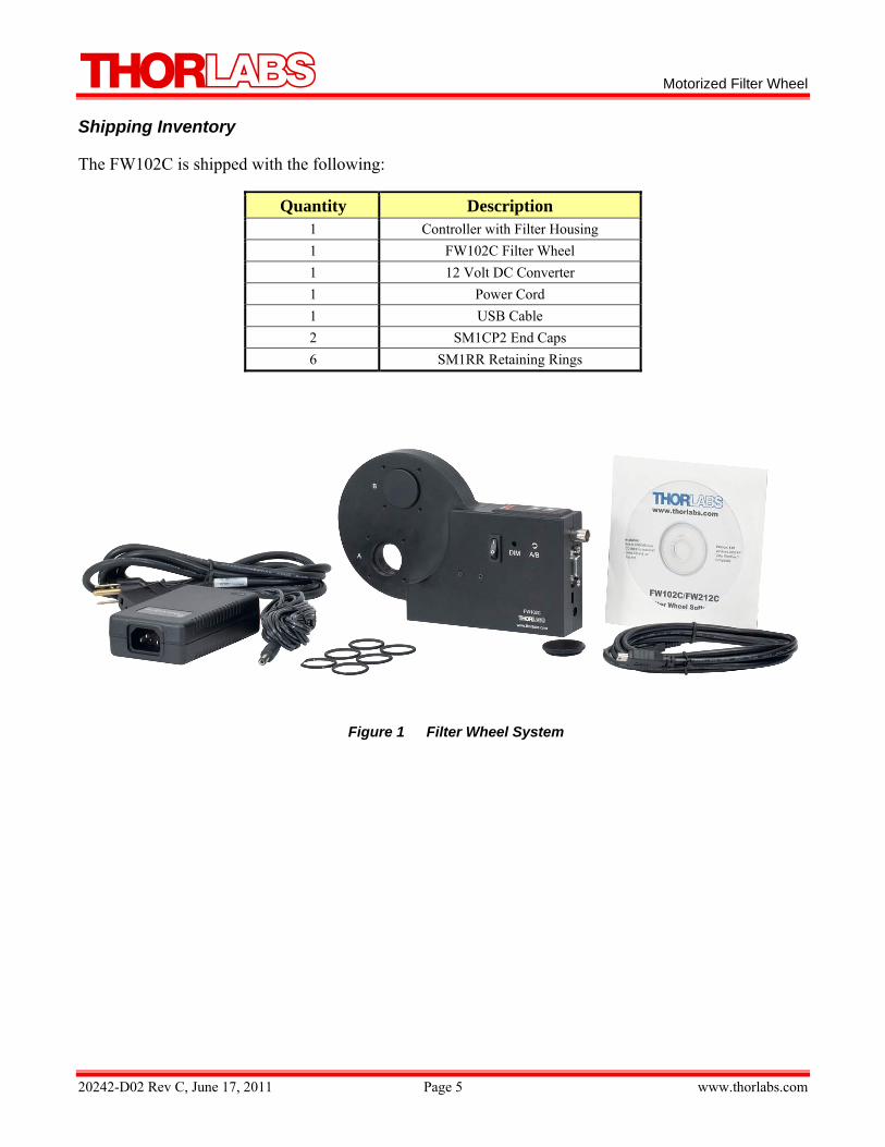
The FW102C is shipped with the following:
Quantity Description 1 Controller with Filter Housing 1 FW102C Filter Wheel 1 12 Volt DC Converter 1 Power Cord 1 USB Cable 2 SM1CP2 End Caps 6 SM1RR Retaining Rings
Figure 1 Filter Wheel System
Motorized Filter Wheel
20242-D02 Rev C, June 17, 2011 Page 6 www.thorlabs.com
Part 2. Basic Operation The following sections describe the basic operation of the motorized filter wheel and application software.
2.1. Changing and Removing Filters
WARNING Prior to changing filters, ensure that the power is off and the unit is disconnected from the
DC source.
The filters can be changed by first removing the filter wheel cover, which is held in place with a single thumbscrew. Filters can then be inserted into the desired locations. The filters are secured to the wheel via SM1RR-1CT retaining rings, which are included with the unit. For easy access, the entire filter wheel can be lifted out of the filter wheel housing. Please note that the rear edge of the threaded filter holes contain a retaining lip that secures one edge of a Ø1" filter. Some filters with a Ø25 mm may need to be mounted between two SM1RR-1CT retaining rings.
When replacing the filter wheel in the housing, slip the wheel over the shaft and turn slightly to allow the gears to mesh. Replace the cover and tighten the thumb screw. It is not necessary to return the wheel to any particular orientation, since the unit will reorient automatically when the power is turned on.
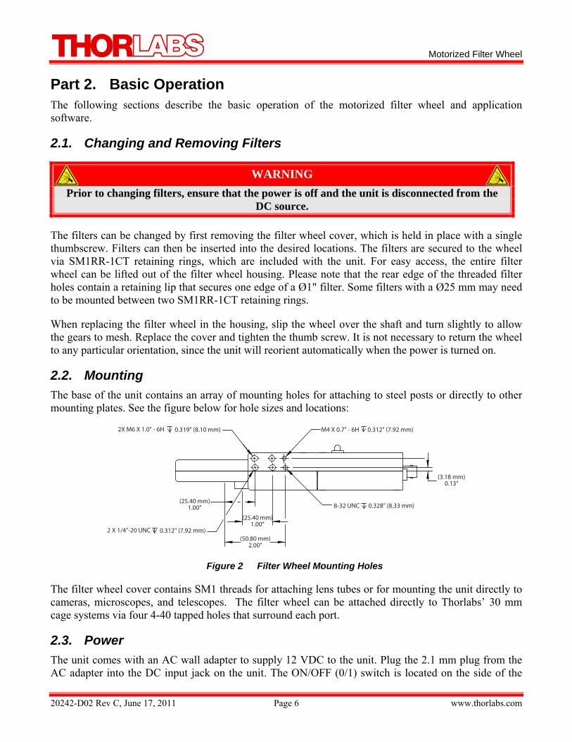
2.2. Mounting The base of the unit contains an array of mounting holes for attaching to steel posts or directly to other mounting plates. See the figure below for hole sizes and locations:
Figure 2 Filter Wheel Mounting Holes
The filter wheel cover contains SM1 threads for attaching lens tubes or for mounting the unit directly to cameras, microscopes, and telescopes. The filter wheel can be attached directly to Thorlabs’ 30 mm cage systems via four 4-40 tapped holes that surround each port.
2.3. Power The unit comes with an AC wall adapter to supply 12 VDC to the unit. Plug the 2.1 mm plug from the AC adapter into the DC input jack on the unit. The ON/OFF (0/1) switch is located on the side of the
2X M6 X 1.0" - 6H 0.319" (8.10 mm)
2 X 1/4"-20 UNC 0.312" (7.92 mm)
(25.40 mm)1.00"
(25.40 mm)1.00"
(50.80 mm)2.00"
M4 X 0.7" - 6H 0.312" (7.92 mm)
8-32 UNC 0.328" (8.33 mm)
(3.18 mm)0.13"
Motorized Filter Wheel
20242-D02 Rev C, June 17, 2011 Page 7 www.thorlabs.com
unit. Upon power up, the unit will display the filter number that is located at the selected aperture. If the wheel is not located at a valid location, it will rotate to the closest valid position.
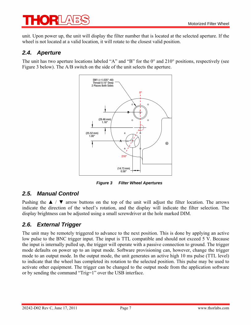
2.4. Aperture The unit has two aperture locations labeled “A” and “B” for the 0° and 210° positions, respectively (see Figure 3 below). The A/B switch on the side of the unit selects the aperture.
Figure 3 Filter Wheel Apertures
2.5. Manual Control Pushing the / arrow buttons on the top of the unit will adjust the filter location. The arrows indicate the direction of the wheel’s rotation, and the display will indicate the filter selection. The display brightness can be adjusted using a small screwdriver at the hole marked DIM.
2.6. External Trigger The unit may be remotely triggered to advance to the next position. This is done by applying an active low pulse to the BNC trigger input. The input is TTL compatible and should not exceed 5 V. Because the input is internally pulled up, the trigger will operate with a passive connection to ground. The trigger mode defaults on power up to an input mode. Software provisioning can, however, change the trigger mode to an output mode. In the output mode, the unit generates an active high 10 ms pulse (TTL level) to indicate that the wheel has completed its rotation to the selected position. This pulse may be used to activate other equipment. The trigger can be changed to the output mode from the application software or by sending the command “Trig=1” over the USB interface.
SM1 (Ø1.035"-40)Thread 0.15" Deep
2 Places Both Sides
(29.46 mm)1.16"
(25.52 mm)1.00"
210°
0°
(14.73 mm)0.58"
2
P
3T2bP
T
ETUO
A
20242-D02 Rev
Part 3.
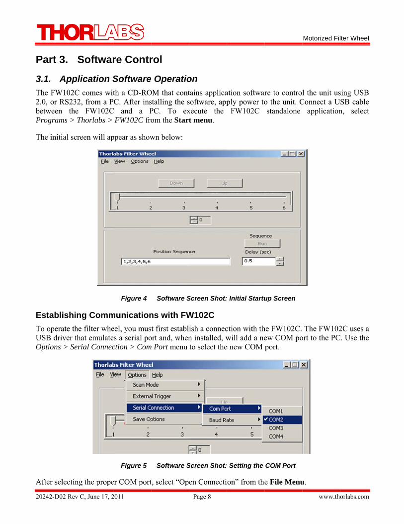
3.1. AppThe FW102C2.0, or RS23between thePrograms >
The initial sc
EstablishiTo operate thUSB driver tOptions > Se
After selectin
v C, June 17, 2
Softwar
plication SC comes wit32, from a Pe FW102CThorlabs >
creen will ap
ing Commhe filter whethat emulateerial Connec
ng the prope
2011
re Contr
Softwareth a CD-RO
PC. After insC and a P
FW102C fro
ppear as show
Figure 4
municationeel, you muses a serial poction > Com
Figure 5
er COM port
rol
e OperatioOM that contstalling the sPC. To exom the Start
wn below:
Software S
ns with FWt first establ
ort and, whenm Port menu
Software S
t, select “Op
Page 8
on tains applicasoftware, appxecute the t menu.
Screen Shot:
W102C ish a connecn installed, wto select the
Screen Shot:
en Connecti
ation softwarply power to
FW102C
: Initial Startu
ction with thwill add a nee new COM
: Setting the
ion” from the
re to controo the unit. Cstandalone
up Screen
he FW102C. ew COM poport.
COM Port
e File Menu
Motorized Fil
www.th
l the unit usConnect a U
application
The FW102ort to the PC
u.
lter Wheel
orlabs.com
sing USB SB cable n, select
2C uses a C. Use the
2
Tt
F
PTs
TSt
Tt
HTs
MTN
20242-D02 Rev
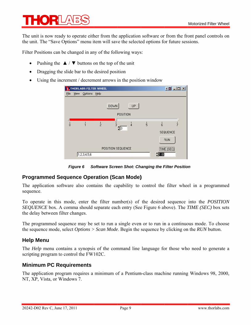
The unit is nthe unit. The
Filter Positio
• Pushi
• Drag
• Using
ProgrammThe applicatsequence.
To operate SEQUENCEthe delay bet
The programthe sequence
Help MenuThe Help mscripting pro
Minimum The applicatNT, XP, Vist
v C, June 17, 2
now ready toe “Save Optio
ons can be ch
ing the /
ging the slid
g the increm
F
med Sequetion softwar
in this modE box. A comtween filter c
mmed sequene mode, selec
u menu containogram to con
PC Requition programta, or Windo
2011
o operate eithons” menu i
hanged in an
buttons o
de bar to the
ment / decrem
Figure 6 So
ence Opere also cont
de, enter thmma should changes.
nce may be ct Options >
s a synopsisntrol the FW
rements m requires a ows 7.
her from the tem will sav
ny of the foll
on the top of
desired posi
ment arrows i
oftware Scre
ration (Sctains the ca
he filter numseparate eac
set to run a > Scan Mode
s of the com102C.
minimum o
Page 9
application ve the selecte
lowing ways
f the unit
ition
in the positio
een Shot: Ch
can Mode)apability to
mber(s) ofch entry (See
single evene. Begin the s
mmand line
of a Pentium
software ored options fo
s:
on window
hanging the F
) control the
the desirede Figure 6 ab
n or to run insequence by
language fo
m-class mach
r from the froor future ses
Filter Positio
filter whee
d sequence bove). The T
n a continuoy clicking on
or those who
hine running
Motorized Fil
www.th
ont panel cosions.
on
el in a prog
into the POTIME (SEC)
ous mode. Tn the RUN bu
o need to ge
g Windows 9
lter Wheel
orlabs.com
ontrols on
grammed
OSITION ) box sets
To choose utton.
enerate a
98, 2000,
Motorized Filter Wheel
20242-D02 Rev C, June 17, 2011 Page 10 www.thorlabs.com
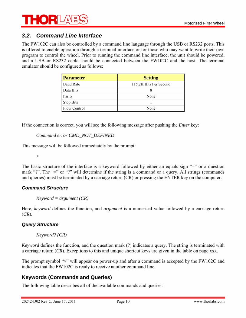
3.2. Command Line Interface The FW102C can also be controlled by a command line language through the USB or RS232 ports. This is offered to enable operation through a terminal interface or for those who may want to write their own program to control the wheel. Prior to running the command line interface, the unit should be powered, and a USB or RS232 cable should be connected between the FW102C and the host. The terminal emulator should be configured as follows:
Parameter Setting Baud Rate 115.2K Bits Per Second Data Bits 8 Parity None Stop Bits 1 Flow Control None
If the connection is correct, you will see the following message after pushing the Enter key:
Command error CMD_NOT_DEFINED
This message will be followed immediately by the prompt:
>
The basic structure of the interface is a keyword followed by either an equals sign “=” or a question mark “?”. The “=” or “?” will determine if the string is a command or a query. All strings (commands and queries) must be terminated by a carriage return (CR) or pressing the ENTER key on the computer.
Command Structure
Keyword = argument (CR)
Here, keyword defines the function, and argument is a numerical value followed by a carriage return (CR).
Query Structure
Keyword? (CR)
Keyword defines the function, and the question mark (?) indicates a query. The string is terminated with a carriage return (CR). Exceptions to this and unique shortcut keys are given in the table on page xxx.
The prompt symbol “>” will appear on power-up and after a command is accepted by the FW102C and indicates that the FW102C is ready to receive another command line.
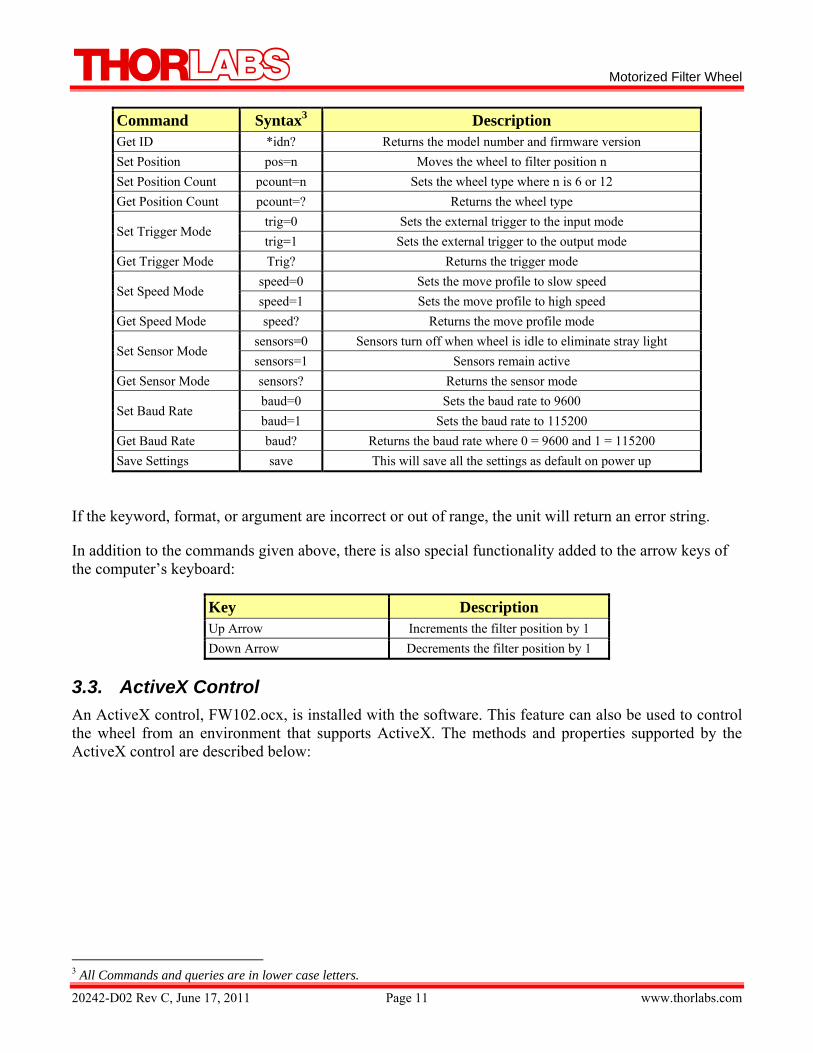
Keywords (Commands and Queries) The following table describes all of the available commands and queries:
Motorized Filter Wheel
20242-D02 Rev C, June 17, 2011 Page 11 www.thorlabs.com
Command Syntax3 Description Get ID *idn? Returns the model number and firmware version Set Position pos=n Moves the wheel to filter position n Set Position Count pcount=n Sets the wheel type where n is 6 or 12 Get Position Count pcount=? Returns the wheel type
Set Trigger Mode trig=0 Sets the external trigger to the input mode trig=1 Sets the external trigger to the output mode
Get Trigger Mode Trig? Returns the trigger mode
Set Speed Mode speed=0 Sets the move profile to slow speed speed=1 Sets the move profile to high speed
Get Speed Mode speed? Returns the move profile mode
Set Sensor Mode sensors=0 Sensors turn off when wheel is idle to eliminate stray light sensors=1 Sensors remain active
Get Sensor Mode sensors? Returns the sensor mode
Set Baud Rate baud=0 Sets the baud rate to 9600 baud=1 Sets the baud rate to 115200
Get Baud Rate baud? Returns the baud rate where 0 = 9600 and 1 = 115200 Save Settings save This will save all the settings as default on power up
If the keyword, format, or argument are incorrect or out of range, the unit will return an error string.
In addition to the commands given above, there is also special functionality added to the arrow keys of the computer’s keyboard:
Key Description Up Arrow Increments the filter position by 1 Down Arrow Decrements the filter position by 1
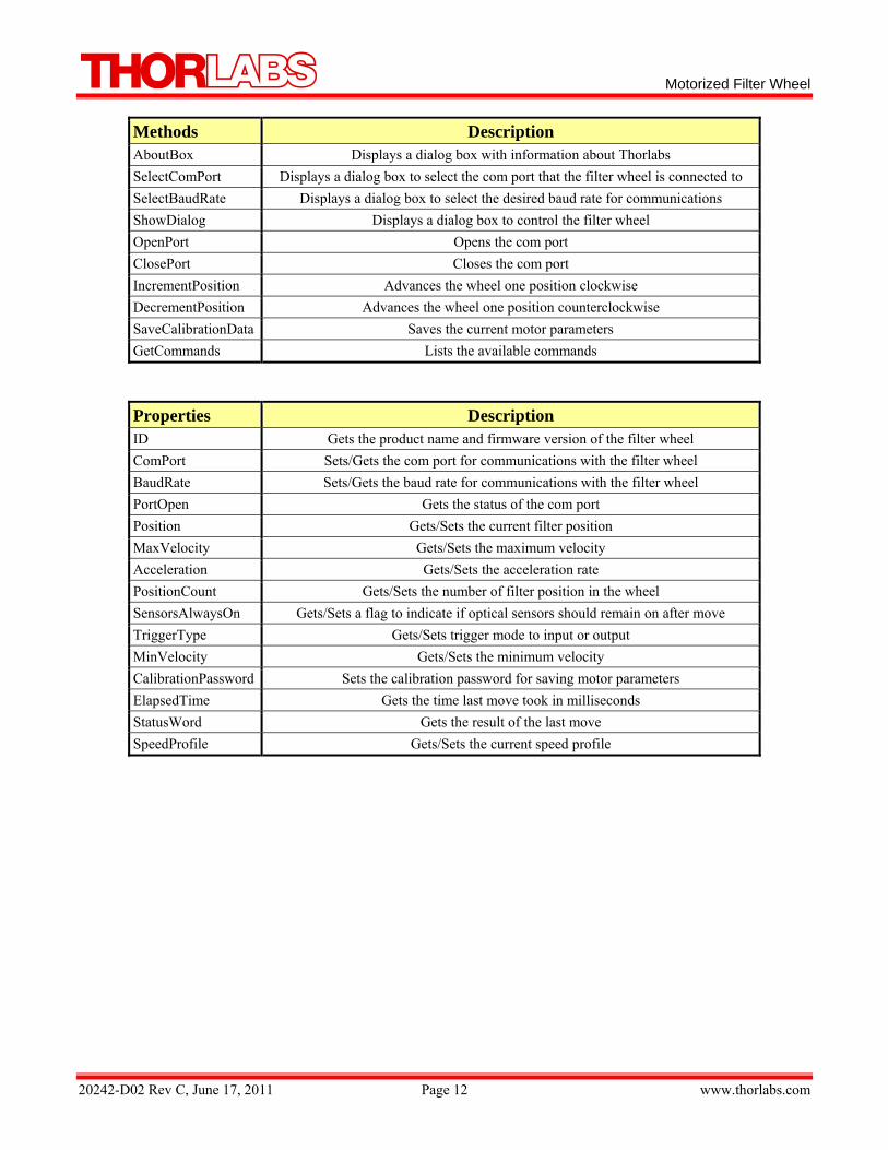
3.3. ActiveX Control An ActiveX control, FW102.ocx, is installed with the software. This feature can also be used to control the wheel from an environment that supports ActiveX. The methods and properties supported by the ActiveX control are described below:
3 All Commands and queries are in lower case letters.
Motorized Filter Wheel
20242-D02 Rev C, June 17, 2011 Page 12 www.thorlabs.com
Methods Description AboutBox Displays a dialog box with information about Thorlabs SelectComPort Displays a dialog box to select the com port that the filter wheel is connected to SelectBaudRate Displays a dialog box to select the desired baud rate for communications ShowDialog Displays a dialog box to control the filter wheel OpenPort Opens the com port ClosePort Closes the com port IncrementPosition Advances the wheel one position clockwise DecrementPosition Advances the wheel one position counterclockwise SaveCalibrationData Saves the current motor parameters GetCommands Lists the available commands
Properties Description ID Gets the product name and firmware version of the filter wheel ComPort Sets/Gets the com port for communications with the filter wheel BaudRate Sets/Gets the baud rate for communications with the filter wheel PortOpen Gets the status of the com port Position Gets/Sets the current filter position MaxVelocity Gets/Sets the maximum velocity Acceleration Gets/Sets the acceleration rate PositionCount Gets/Sets the number of filter position in the wheel SensorsAlwaysOn Gets/Sets a flag to indicate if optical sensors should remain on after move TriggerType Gets/Sets trigger mode to input or output MinVelocity Gets/Sets the minimum velocity CalibrationPassword Sets the calibration password for saving motor parameters ElapsedTime Gets the time last move took in milliseconds StatusWord Gets the result of the last move SpeedProfile Gets/Sets the current speed profile
2
PDtw
RTfa
Wc
20242-D02 Rev
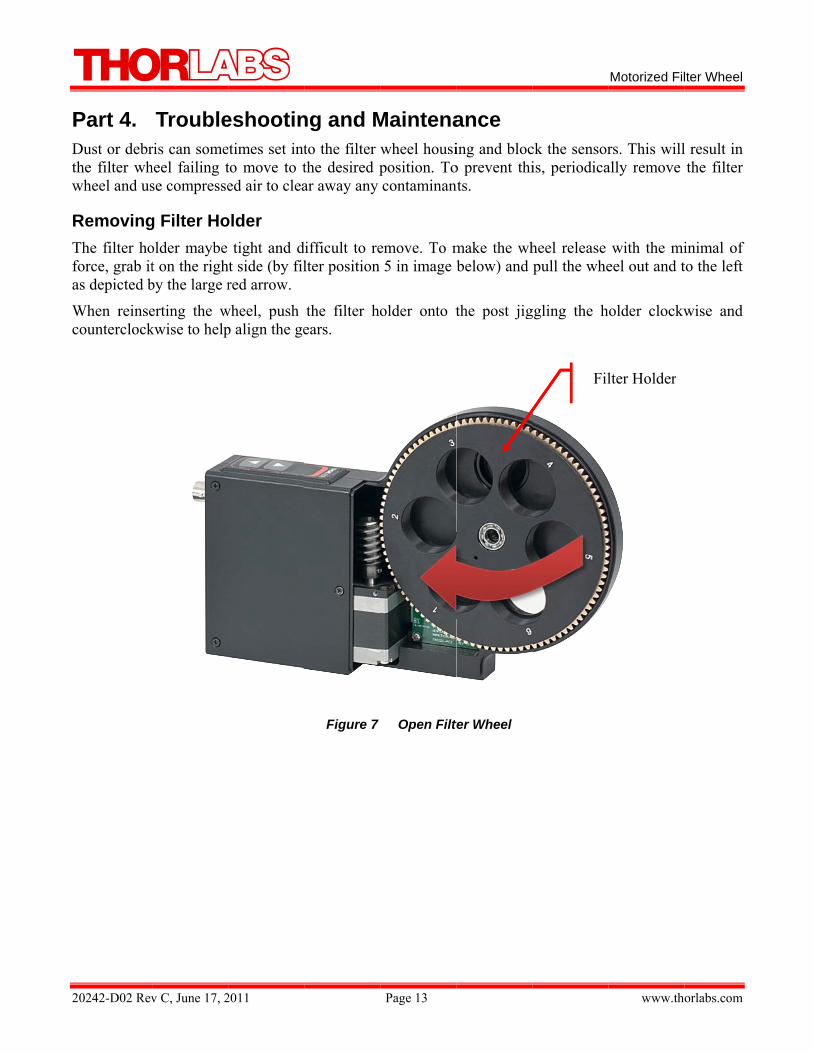
Part 4. Dust or debrthe filter whwheel and us
RemovingThe filter hoforce, grab itas depicted b
When reinsecounterclock
v C, June 17, 2
Troubleris can someheel failing tse compresse
g Filter Hoolder maybe t on the righby the large r
erting the wkwise to help
2011
eshootinetimes set intto move to ted air to clea
older tight and d
ht side (by filred arrow.
wheel, push p align the ge
ng and Mto the filter the desired par away any
difficult to relter position
the filter hoears.
Figure 7
Page 13
Maintenawheel housiposition. Tocontaminan
emove. To m5 in image b
older onto t
Open Filt
ance ing and bloco prevent thints.
make the whbelow) and
the post jig
ter Wheel
ck the sensoris, periodica
heel release pull the whe
ggling the h
Fil
Motorized Fil
www.th
rs. This willally remove
with the mieel out and t
older clockw
lter Holder
lter Wheel
orlabs.com
l result in the filter
inimal of to the left
wise and
Motorized Filter Wheel
20242-D02 Rev C, June 17, 2011 Page 14 www.thorlabs.com
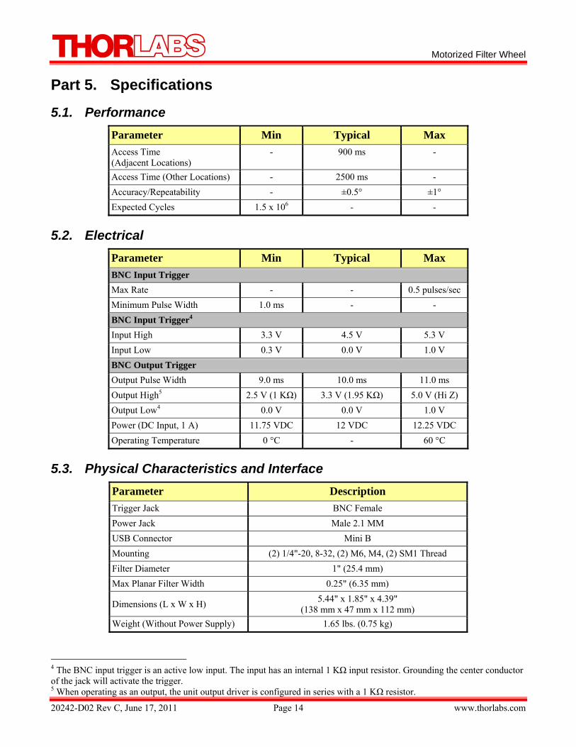
Part 5. Specifications
5.1. Performance Parameter Min Typical Max Access Time (Adjacent Locations)
- 900 ms -
Access Time (Other Locations) - 2500 ms - Accuracy/Repeatability - ±0.5° ±1° Expected Cycles 1.5 x 10⁶ - -
5.2. Electrical Parameter Min Typical Max BNC Input Trigger Max Rate - - 0.5 pulses/sec Minimum Pulse Width 1.0 ms - - BNC Input Trigger4 Input High 3.3 V 4.5 V 5.3 V Input Low 0.3 V 0.0 V 1.0 V BNC Output Trigger Output Pulse Width 9.0 ms 10.0 ms 11.0 ms Output High5 2.5 V (1 KΩ) 3.3 V (1.95 KΩ) 5.0 V (Hi Z) Output Low4 0.0 V 0.0 V 1.0 V Power (DC Input, 1 A) 11.75 VDC 12 VDC 12.25 VDC Operating Temperature 0 °C - 60 °C
5.3. Physical Characteristics and Interface Parameter Description Trigger Jack BNC Female Power Jack Male 2.1 MM USB Connector Mini B Mounting (2) 1/4"-20, 8-32, (2) M6, M4, (2) SM1 Thread Filter Diameter 1" (25.4 mm) Max Planar Filter Width 0.25" (6.35 mm)
Dimensions (L x W x H) 5.44" x 1.85" x 4.39" (138 mm x 47 mm x 112 mm)
Weight (Without Power Supply) 1.65 lbs. (0.75 kg)
4 The BNC input trigger is an active low input. The input has an internal 1 KΩ input resistor. Grounding the center conductor of the jack will activate the trigger. 5 When operating as an output, the unit output driver is configured in series with a 1 KΩ resistor.
Motorized Filter Wheel
20242-D02 Rev C, June 17, 2011 Page 15 www.thorlabs.com
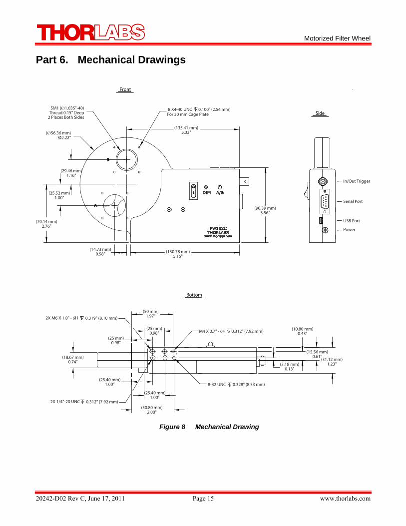
Part 6. Mechanical Drawings
Figure 8 Mechanical Drawing
SM1 (Ø1.035"-40)Thread 0.15" Deep
2 Places Both Sides
(Ø56.36 mm)Ø2.22"
(29.46 mm)1.16"
(25.52 mm)1.00"
(70.14 mm)2.76"
(14.73 mm)0.58" (130.78 mm)
5.15"
(135.41 mm)5.33"
2X M6 X 1.0" - 6H 0.319" (8.10 mm)
(18.67 mm)0.74"
2X 1/4"-20 UNC 0.312" (7.92 mm)
(25 mm)0.98"
(25.40 mm)1.00"
(25.40 mm)1.00"
(50.80 mm)2.00"
M4 X 0.7" - 6H 0.312" (7.92 mm)
8 X4-40 UNC 0.100" (2.54 mm)For 30 mm Cage Plate
(90.39 mm)3.56"
(50 mm)1.97"
(25 mm)0.98"
8-32 UNC 0.328" (8.33 mm)
(3.18 mm)0.13"
(15.56 mm)0.61"
(31.12 mm)1.23"
(10.80 mm)0.43"
In/Out Trigger
Serial Port
USB Port
Power
Front
Side
Bottom
2
PACt
Ao
If
7Ir
7ITp
Tl
20242-D02 Rev
Part 7. As required Community to return “en
• This • Sold • Mark• Sold • Curre• Still c
As the WEEof life take b
• Pure drive
• Comp• Mech• Left o
If you wish tfor further in
7.1. WasIf you do notrecovery. Do
7.2. EcoIt is well knoThe aim of products in th
The intent oflife products
v C, June 17, 2
Regulatby the WE
and the corrnd of life” un
offer is validafter August
ked correspoto a compan
ently owned complete, no
EE directive back service
OEM produr cards) ponents hanics and opover parts of
to return a Tnformation.
ste Treatmt return an “eo not dispose
ological Bown that WEthe Europeahe future.
f the WEEE will thereby
2011
tory EEE (Wasteresponding nnits without i
d for Thorlabt 13, 2005 ndingly with
ny or institutby a compa
ot disassemb
applies to sedoes not refe
ucts, that me
ptics f units disass
Thorlabs uni
ment is Yend of life” ue of the unit
BackgrouEEE pollutesan RoHS di
directive is y avoid nega
Electrical national lawincurring dis
bs electrical
h the crossedte within the any or institubled and not
elf-containedfer to other T
eans assemb
sembled by t
it for waste r
Your Ownunit to Thorlin a litter bin
nd s the environirective is t
to enforce tative impacts
Page 16
and Electros, Thorlabs sposal charg
and electron
d out “wheelEC
ute within thecontaminate
d operationaThorlabs prod
blies to be bu
the user (PC
recovery, pl
n Responlabs, you mun or at a pub
nment by relo reduce th
the recyclings on the envi
onic Equipmoffers all enes.
nic equipme
lie bin” logo
e EC ed
al electrical aducts, such a
uilt into a u
CB’s, housing
ease contact
nsibility ust hand it toblic waste di
leasing toxiche content o
g of WEEE. ironment.
ment Directivnd users in th
nt:
o (see right)
and electronas:
unit by the u
gs etc.).
t Thorlabs o
o a companysposal site.
c products duof toxic subs
A controlle
Motorized Fil
www.th
ve) of the Ehe EC the p
nic products,
user (e. g. OE
or your neare
y specialized
uring decomstances in e
d recycling
Wheelie Bin
lter Wheel
orlabs.com
European ossibility
, this end
EM laser
est dealer
d in waste
mposition. electronic
of end of
n Logo

Motorized Filter Wheel
20242-D02 Rev C, June 17, 2011 Page 17 www.thorlabs.com
Part 8. Thorlabs Worldwide Contacts
USA, Canada, and South America Thorlabs, Inc. 435 Route 206 Newton, NJ 07860 USA Tel: 973-579-7227 Fax: 973-300-3600 www.thorlabs.com email: [email protected]
Europe Thorlabs GmbH Hans-Böckler-Str. 6 85221 Dachau Germany Tel: +49-(0)8131-5956-0 Fax: +49-(0)8131-5956-99 www.thorlabs.de email: [email protected]
UK and Ireland Thorlabs LTD. 1 Saint Thomas Place, Ely Cambridgeshire CB7 4EX Great Britain Tel: +44 (0)1353-654440 Fax: +44 (0)1353-654444 www.thorlabs.de email: [email protected]
France Thorlabs SAS 109, rue des Côtes 78600 Maisons-Laffitte France Tel: +33 (0) 970 444 844 Fax: +33 (0) 811 381 748 www.thorlabs.de email: [email protected]
Scandinavia Thorlabs Sweden AB Box 141 94 400 20 Göteborg Sweden Tel: +46-31-733-30-00 Fax: +46-31-703-40-45 www.thorlabs.de email: [email protected]
Japan Thorlabs Japan Inc. Higashi Ikebukuro Q Building 1st Floor 2-23-2 Toshima-ku, Tokyo 170-0013 Japan Tel: +81-3-5979-8889 Fax: +81-3-5979-7285 www.thorlabs.jp email: [email protected]
China Thorlabs China Oasis Middlering Centre 3 Building 712 Room 915 Zhen Bei Road Shanghai China Tel: +86 (0)21-32513486 Fax: +86 (0)21-32513480 www.thorlabs.com email: [email protected]

Thorlabs, I435 Route 20Newton, NJ 0 Phone: (973)www.thorlab
Inc. 06N 07860 USA
) 579-7227 ♦ Fbs.com
Fax: (973) 300-3600


