DN
3-4
3-1
3-2
3-3
3-3.8
3-H
REF10
1-L
3-3.5
REF1
3-K
R.2
3-5
3-G
4-22
3-J3-L
3-M
3-N
3-P
3-Q
3-R
REF12
4-17
4-18
4-19
4-20
4-21
4-16.8
4-19.4
4-E
4-G
4-K
4-M
4-Q 4-R 4-S
4-Q.2
1
2
3
4
8
7
8
9A
9C
Cooler Remote Condensing Unit
Freezer Remote Condensing Unit
FREEZER
COOLER
11
9D
1010
1010
1010 10
9B
11
12
12
12 12
13
DRY FOOD
STORAGE
STAFF
TOILET
OFFICE
17 18 18
19 20
21
2223
24
16
27 27
28
29
30
31
3332
23
24
16
34
38
37
39
40
1819
41
42
18
44
43
50
52
45
46
55
54
53
23
24
59
58
6061
19
62
63 64
65
66
6767
71
70A70B
72
70
73
74
75
76A
76
77
78
79
82
82
STAIR 7
ST7-1
CUST
145B
STAIR 6
ST6-1
TOILET
T1-5B
GIRLS TOILET
T1-6A
TOILET
T1-6B
CORRIDOR
C106
51
1
2
34
5
NORTH ARROW
KEYPLAN
DRAWING NAME:
DRAWN BY:
REVIEWED BY:
SCALE:
JOB NO:
DATE:
DRAWING NUMER:
KEYNOTE LEGEND:
CABOT STREETBEVERLY, MA 01915
_ÉîÉêäó
jfaaib
p`elli
Cop
yrig
ht c
201
5 A
i3 A
rchi
tect
s, L
LC
VMB=ÅçåëíêìÅíáçå
ÇçÅìãÉåíë
klq=clo
`lkpqor`qflk
1/4" = 1'-0"
8/1
2/2
016 9
:11:2
3 A
M C:\
Users
\Rob\D
eskto
p\R
evit W
ork
File
s\6
46 B
EV
ER
LY
MS
Revit2016\B
MS
-FO
OD
SE
RV
ICE
_R
ob.r
vt
1403.00
08/12/16
RM
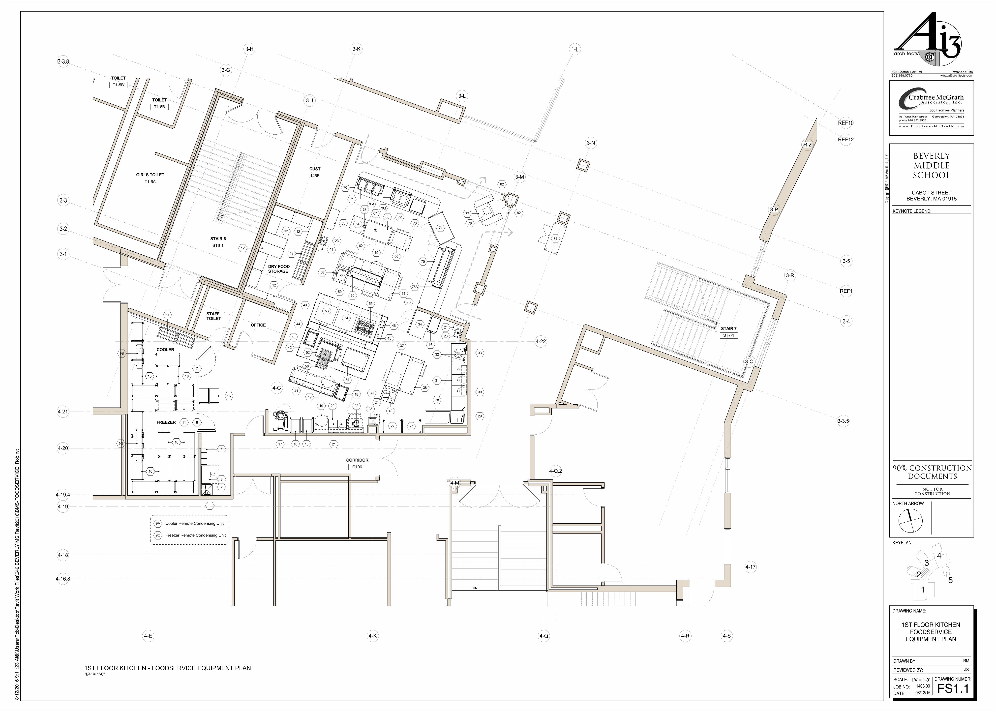
1ST FLOOR KITCHENFOODSERVICE
EQUIPMENT PLAN
FS1.1
JS 1/4" = 1'-0"
1ST FLOOR KITCHEN - FOODSERVICE EQUIPMENT PLAN

2-G
REF10 REF11
REF4
REF5
1-L
REF2
2-4
R.1R.2
R.3
REF7
REF8
2-3
2-F.5 2-G.8
2-H
REF9
REF13
REF14
REF15
82
89
83
85
84
85A
87
7886
88
89
82
91
83
90A
86
90
87
78
88
1
2
34
5
NORTH ARROW
KEYPLAN
DRAWING NAME:
DRAWN BY:
REVIEWED BY:
SCALE:
JOB NO:
DATE:
DRAWING NUMER:
KEYNOTE LEGEND:
CABOT STREETBEVERLY, MA 01915
_ÉîÉêäó
jfaaib
p`elli
Cop
yrig
ht c
201
5 A
i3 A
rchi
tect
s, L
LC
VMB=ÅçåëíêìÅíáçå
ÇçÅìãÉåíë
klq=clo
`lkpqor`qflk
1/4" = 1'-0"
8/1
2/2
016 9
:11:2
6 A
M C:\
Users
\Rob\D
eskto
p\R
evit W
ork
File
s\6
46 B
EV
ER
LY
MS
Revit2016\B
MS
-FO
OD
SE
RV
ICE
_R
ob.r
vt
1403.00
08/12/16
RM
1ST FLOOR SERVERYFOODSERVICE
EQUIPMENT PLAN
FS1.2
JS
1/4" = 1'-0"
1ST FLOOR SERVERY - FOODSERVICE EQUIPMENT PLAN

J-Box by EC
Conduit by ECSealing hub by EC
Walk-in ceiling panelWalk-in ceiling panel
EC to cut holes as directed by KECVinyl sleeve and grommets by EC
Rigid steel conduitby EC thru walk-in panel
EC to seal between conduit andsleeve with expanding foam
EC to seal betweenfixture base and ceiling
Light fixture provided by KEC
Notes:
1. All light fixture to be furnished by KEC
2. Mounting light fixtures, all conduit and interwiring by EC
3. All conduit to be on exterior of walk-in by EC
4. All penetrations thru walk-in panels to be thoroughly sealed by EC
3-43-1
3-2
3-3
3-3.8
3-H 1-L
3-3.5
REF1
3-K
3-5
3-G
4-22
3-J3-L
3-M
3-N
4-19
4-20
4-21
4-19.4
4-E
4-G
4-K
4-M
4-Q
4-Q.2
FD
120/1 +96" DFA BTC
208/1 +96" DFA BTC
1" IW to FD by KEC
1" IW to FD by KEC
1/2" H&CW 36" BTC(hose bibb by PC)
Drain in floor
24" floor typemop sink by PC
Light fixtures by KECmounted & wired by EC
Light fixtures by KECmounted & wired by EC
10 A - 208/3 +48" BTC
FS
20 A circuit - 120/1 DR +50"
1/2" H&CW +18" BTC
20 A circuit - 120/1 DR +50"
(2) 2" IW to FS
1/2" HW +22" BTC
1-1/2" W +20" BTC
1/2" CW +22" BTC
1/2" CW +42" BTC
1/2" HW +42" BTC
45.4 A - 208/3 +18" BTC
FS
3/4" 120°FH&CW +16" BTC
3/4" 120°FH&CW +16" BTC
(3) 2" W manifold thru GI by PC(verify GI rough-in location)
6.6 A - 208/3 +54" BTC
2" W +12" BTC
1/2" CW +18" BTC
1/2" CW +18" BTC
1/2" HW +18" BTC
1/2" CW +22" BTC
1/2" HW +22" BTC
1-1/2" W +20" BTC
8.2 A - 120/1 DR +90"
FS
2" IW to FS
1/2" H&CW +4" BTC
(3) 20 A circuit - 120/1 +4"BT mounted DR by KEC
(2) 20 A circuit - 120/1 +4"BT mounted DR by KEC
1/2" HW +22" BTC
1-1/2" W +20" BTC
1/2" CW +22" BTC
(2) 20 A circuit - 120/1in ceiling for drop cord
(2) 20 A circuit - 120/1 +4"BT mounted DR by KEC
(2) 20 A circuit - 1020/1 +4"BT mountred DR by KEC
1.1 KW - 120/1 +96" DFA BTC
1.5 KW - 120/1 +96" DFA BTC
1-1/2" IW to FS
26" x 26" x 9" deeprecess BFF by GC
26" x 42" x 9" deeprecess BFF by GC
(2) 3" W conn 7" BFF
2" G @ 653 MBTU+80" DFA BTC
1" HW +80" DFA BTC
1" CW +80" DFA BTC
50 A circuit - 120/208/3 +80" DFA BTC
120/1; J-box +9'-6" for connection to buildingalarm system & equipment shutdown
See Note E-46 (DFA)
20 A circuit - 120/1 DFA for conn to ventilator control & hood lights at Items 42 & 43;EC to provide CAT5 connection to remote touch screen (cable supplied with system);EC to provide high voltage conns from VFDs to EHX fan;EC to provide wiring to temp sensors at hoods;EC to provide wiring to room temp sensors;EC to provide wiring from building management system remote control
E-46
Field connections by Related Tradesfrom UDS (Item 44) to Items 51 thru 55
(flexible water & gas connectors provided by KEC)
Support by GC fromstructure above for Item 60
FS
(3) 20 A circuit - 120/1 +4"BT mounted DR by KEC
1" IW to FS
3.0 KW - 208/1 +4" BTmounted SW by KEC
1" IW to FS
(3) 20 A circuit - 120/1 +4"BT mounted DR by KEC
20 A circuit - 208/1 +4" BTmounted NEMA 6-20R by KEC
Flush-in-floor data receptacle
20 A circuit - 120/1DR flush-in-floor
20 A circuit - 120/1DR +85" DFA
Recessed type fire suppression pullstation +48" (conceal conduit in wall)
12'-4"
3'-1"
6'-2"
3'-1"
5'-0"
1'-2"
5'-0"
9"
9"
2'-10"
5'-8"
2'-10"
EXH 2,837 total CFM thru (2) 10" x 13"collars @ 0.653" SP +9'-6" AFF
EXH 2,663 total CFM thru (2) 10" x 12"collars @ 0.582" SP +9'-6" AFF
Power to lights from Item 46
Power to lights from Item 46
3"
FM
7"
deep r
ecess b
y G
C
2"
Fin
ished f
loor
& s
ettin
g b
ed b
y G
C4"
1"
Finished Ceiling by GC
Closure Panel by KEC
Webs by KEC Building Wall
Partition Panel
Entrance Door
Concrete Fillby Others
Anti-condensateHeater (for BelowFreezing Rooms)
Exterior Panel
Insulated Wall, Roof& Floor Panels by KEC
Building Floor Depression by GC Leveling Sand by KEC
6-1/2"
Grate Opening1-1/2"1-1/2"
1-1/2"1-1/2"
1" 1"
3-3/8"
1"
3"9"
3/4" Clear
4" C/C 1" C/C
2" min
Fiberglass Grating
Flush withfinished floor
Back fill by GC
4'-0" 1'-6" 4'-0"
1'-4"Item 9C
29" high315 lbs
Item 9A29" high330 lbs
TBD - 208/3 TBD - 208/3
Pitch pocket by GCRoof supports by GC
Air flo
w
Air flo
w
3'-0" 2'-0"
1'-0"
3'-0"
Clearance
Mount on roof(verify location) 1
2
34
5
NORTH ARROW
KEYPLAN
DRAWING NAME:
DRAWN BY:
REVIEWED BY:
SCALE:
JOB NO:
DATE:
DRAWING NUMER:
KEYNOTE LEGEND:
CABOT STREETBEVERLY, MA 01915
_ÉîÉêäó
jfaaib
p`elli
Cop
yrig
ht c
201
5 A
i3 A
rchi
tect
s, L
LC
VMB=ÅçåëíêìÅíáçå
ÇçÅìãÉåíë
klq=clo
`lkpqor`qflk
As indicated
8/1
2/2
016 9
:11:3
0 A
M C:\
Users
\Rob\D
eskto
p\R
evit W
ork
File
s\6
46 B
EV
ER
LY
MS
Revit2016\B
MS
-FO
OD
SE
RV
ICE
_R
ob.r
vt
1403.00
08/12/16
RM
1ST FLOOR KITCHENFOODSERVICE
EQUIPMENT ROUGH-INPLAN
FS1.3
JS
1/4" = 1'-0"
1ST FLOOR KITCHEN - FOODSERVICE EQUIPMENT ROUGH-IN PLAN
1/4" = 1'-0"FS1.3
1 Detail - Exhaust Ventilator (Items 42 & 43)
NTSFS1.3
2 Section - Walk-in Typical
NTSFS1.3
3 Section - Floor Trough & Grate
Abbreviations used:
A Amperes EXH Exhaust IW Indirect waste
AFF Above finished floor FD Floor drain KEC Kitchen Equip. Contractor
BFF Below finished floor FFD Funnel floor drain KW Kilowatt
BTC Branch to connection FHW Fahrenheit hot water MBTU BTU per hour/1000
C&P Cord & plug provided FS Floor sink MUA Make-up air
CFM Cubic feet per minute G Gas PC Plumbing Contractor
CR Condensate return GC General Contractor QD Quick disconnect
CW Cold water GI Grease interceptor SP Static pressure (WG)
DFA Drop from above HP Horsepower SR Single receptacle
DR Duplex receptacle HW Hot water SS Steam supply
EC Electrical contractor H&CW Hot & cold water W Waste (direct connection)
Notes: Following apply to all Foodservice Equipment Drawings.Connections, stub-outs and dimensions shown are to be used for estimating engineering requirementsonly. No architectural or engineering service is intended or assumed.
The Kitchen Equipment Contractor shall provide accurate 1/4"=1'-0" stub-outs plans showing exactsizes and locations of all service stubs through walls and/or floors. Services of fixtures shall shall comeout of walls whenever possible allowing clearance for traps, valves, switches, and the like.
Traps, drainlines, grease interceptors, shut-off valves and connecting piping shall be provided andinstalled by the Plumbing Sub-Contractor.
Conduit, junction boxes, outlets, disconnects, and connecting wiring shall be provided and installed bythe Electrical Sub-Contractor. Interwiring of refrigeration components and remote controls such asfound on a garbage disposer shall be installed by the Electrical Sub-Contractor.
Blowers, ductwork and duct connections shall be provided and installed by the Heating and VentilationSub-Contractor. Controls for such systems shall be provided and installed by the specified sub-contractor.
NTSFS1.3
4 Detail - Remote Condensing UnitsNTS
Typical Detail - Refrigerated Room Light Fixture

2-G
REF10 REF11
REF4
REF5
1-L
REF2
2-4
R.1R.2
R.3
REF7
REF8
2-3
2-F.5 2-G.8
2-H
REF9
REF13
REF14
REF15
13.3 A - 120/1 DR +48"
8.9 A - 120/1 DR +24"
1.1 KW - 208/1 +24" BTmounted control by KEC
16 A - 120/1 DR +24"
20 A circuit - 120/1 DR +24"
Data receptacle +24"
13.3 A - 120/1 DR +48"
1" IW to FS
6.8 A - 120/1 DR +24"
16 A - 120/1 DR +24"
20 A circuit - 120/1 DR +24"
Data receptacle +24"
FS
1
2
34
5
NORTH ARROW
KEYPLAN
DRAWING NAME:
DRAWN BY:
REVIEWED BY:
SCALE:
JOB NO:
DATE:
DRAWING NUMER:
KEYNOTE LEGEND:
CABOT STREETBEVERLY, MA 01915
_ÉîÉêäó
jfaaib
p`elli
Cop
yrig
ht c
201
5 A
i3 A
rchi
tect
s, L
LC
VMB=ÅçåëíêìÅíáçå
ÇçÅìãÉåíë
klq=clo
`lkpqor`qflk
1/4" = 1'-0"
8/1
2/2
016 9
:11:3
1 A
M C:\
Users
\Rob\D
eskto
p\R
evit W
ork
File
s\6
46 B
EV
ER
LY
MS
Revit2016\B
MS
-FO
OD
SE
RV
ICE
_R
ob.r
vt
1403.00
08/12/16
RM
1ST FLOOR SERVERYFOODSERVICE
EQUIPMENT ROUGH-INPLAN
FS1.4
JS 1/4" = 1'-0"
1ST FLOOR SERVERY - FOODSERVICE EQUIPMENT ROUGH-IN PLAN
Abbreviations used:
A Amperes EXH Exhaust IW Indirect waste
AFF Above finished floor FD Floor drain KEC Kitchen Equip. Contractor
BFF Below finished floor FFD Funnel floor drain KW Kilowatt
BTC Branch to connection FHW Fahrenheit hot water MBTU BTU per hour/1000
C&P Cord & plug provided FS Floor sink MUA Make-up air
CFM Cubic feet per minute G Gas PC Plumbing Contractor
CR Condensate return GC General Contractor QD Quick disconnect
CW Cold water GI Grease interceptor SP Static pressure (WG)
DFA Drop from above HP Horsepower SR Single receptacle
DR Duplex receptacle HW Hot water SS Steam supply
EC Electrical contractor H&CW Hot & cold water W Waste (direct connection)
3-4
3-1
3-2
3-3
3-3.8
3-H
REF10
1-L
3-3.5
REF1
3-K
R.1R.2
3-5
3-G
4-22
3-J3-L
3-M
3-N
3-P
3-Q
3-R
REF12
4-G
4-K
103
101
102
105
105
106106
106106
107
108
106
106
111
112
113
114116
115
117
117
118
121
122121A
123121B
124
125
126
127A
127
128
129
132
132
130
MEDIA READING
AREA
317C
KITCHEN
345
STAIR 6
ST6-3
GIRLS TOILET
T3-6A
TOILET
T3-6B
KITCHEN
OFFICE
109
1
2
34
5
NORTH ARROW
KEYPLAN
DRAWING NAME:
DRAWN BY:
REVIEWED BY:
SCALE:
JOB NO:
DATE:
DRAWING NUMER:
KEYNOTE LEGEND:
CABOT STREETBEVERLY, MA 01915
_ÉîÉêäó
jfaaib
p`elli
Cop
yrig
ht c
201
5 A
i3 A
rchi
tect
s, L
LC
VMB=ÅçåëíêìÅíáçå
ÇçÅìãÉåíë
klq=clo
`lkpqor`qflk
1/4" = 1'-0"
8/1
2/2
016 9
:11:3
3 A
M C:\
Users
\Rob\D
eskto
p\R
evit W
ork
File
s\6
46 B
EV
ER
LY
MS
Revit2016\B
MS
-FO
OD
SE
RV
ICE
_R
ob.r
vt
1403.00
08/12/16
RM
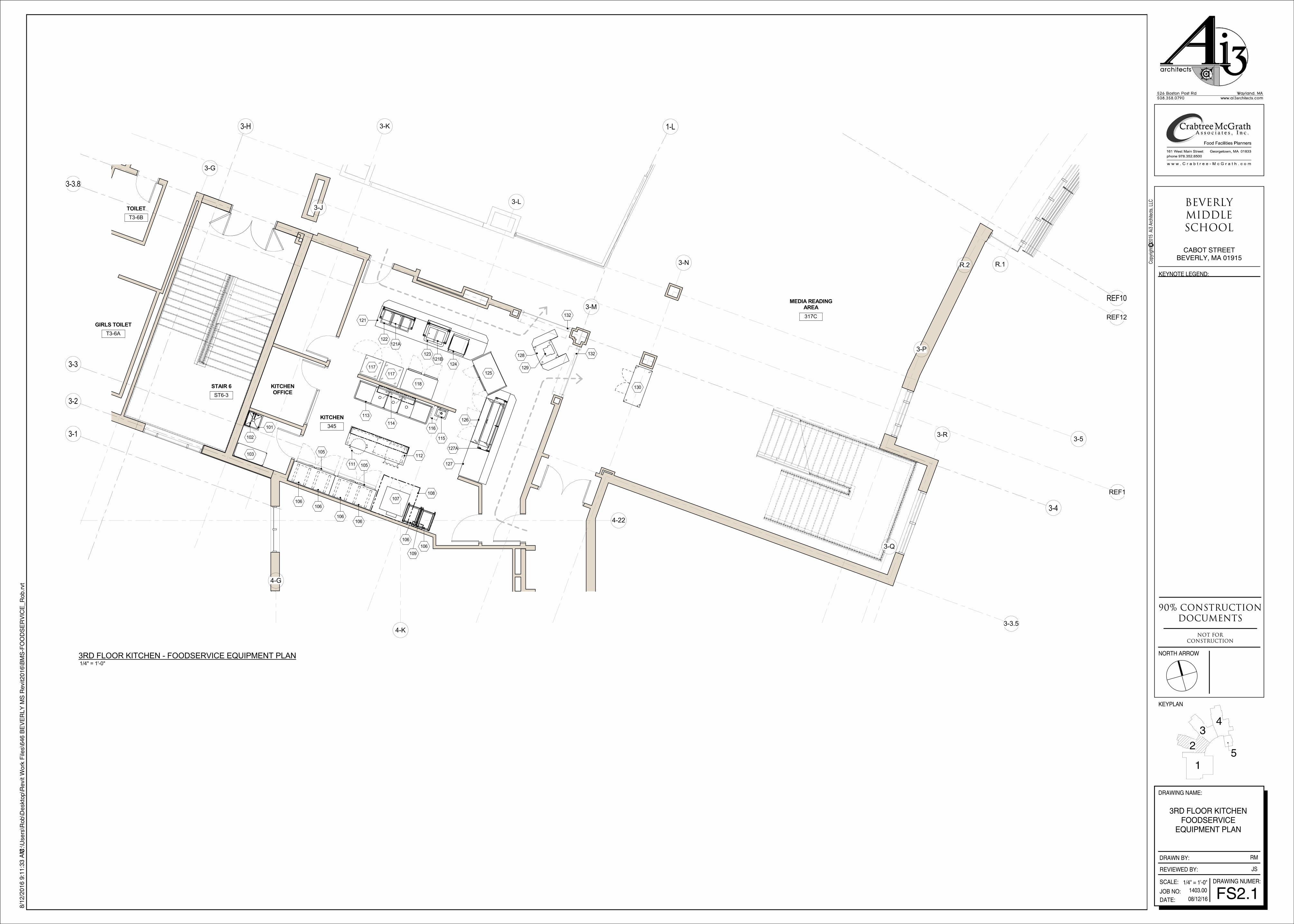
3RD FLOOR KITCHENFOODSERVICE
EQUIPMENT PLAN
FS2.1
JS
1/4" = 1'-0"
3RD FLOOR KITCHEN - FOODSERVICE EQUIPMENT PLAN
2-G
2-1
2-2
REF10 REF11
REF4
REF5
1-L
REF2
2-4
R.1R.2
R.3
REF7
REF8
2-3
2-F.5 2-G.8
2-H
REF9
REF13
REF14
REF15
133
134
135A
136
135
139
137
129 138
132
133
142
143A
136
143
137
129
138
139
1
2
34
5
NORTH ARROW
KEYPLAN
DRAWING NAME:
DRAWN BY:
REVIEWED BY:
SCALE:
JOB NO:
DATE:
DRAWING NUMER:
KEYNOTE LEGEND:
CABOT STREETBEVERLY, MA 01915
_ÉîÉêäó
jfaaib
p`elli
Cop
yrig
ht c
201
5 A
i3 A
rchi
tect
s, L
LC
VMB=ÅçåëíêìÅíáçå
ÇçÅìãÉåíë
klq=clo
`lkpqor`qflk
1/4" = 1'-0"
8/1
2/2
016 9
:11:3
5 A
M C:\
Users
\Rob\D
eskto
p\R
evit W
ork
File
s\6
46 B
EV
ER
LY
MS
Revit2016\B
MS
-FO
OD
SE
RV
ICE
_R
ob.r
vt
1403.00
08/12/16
RM
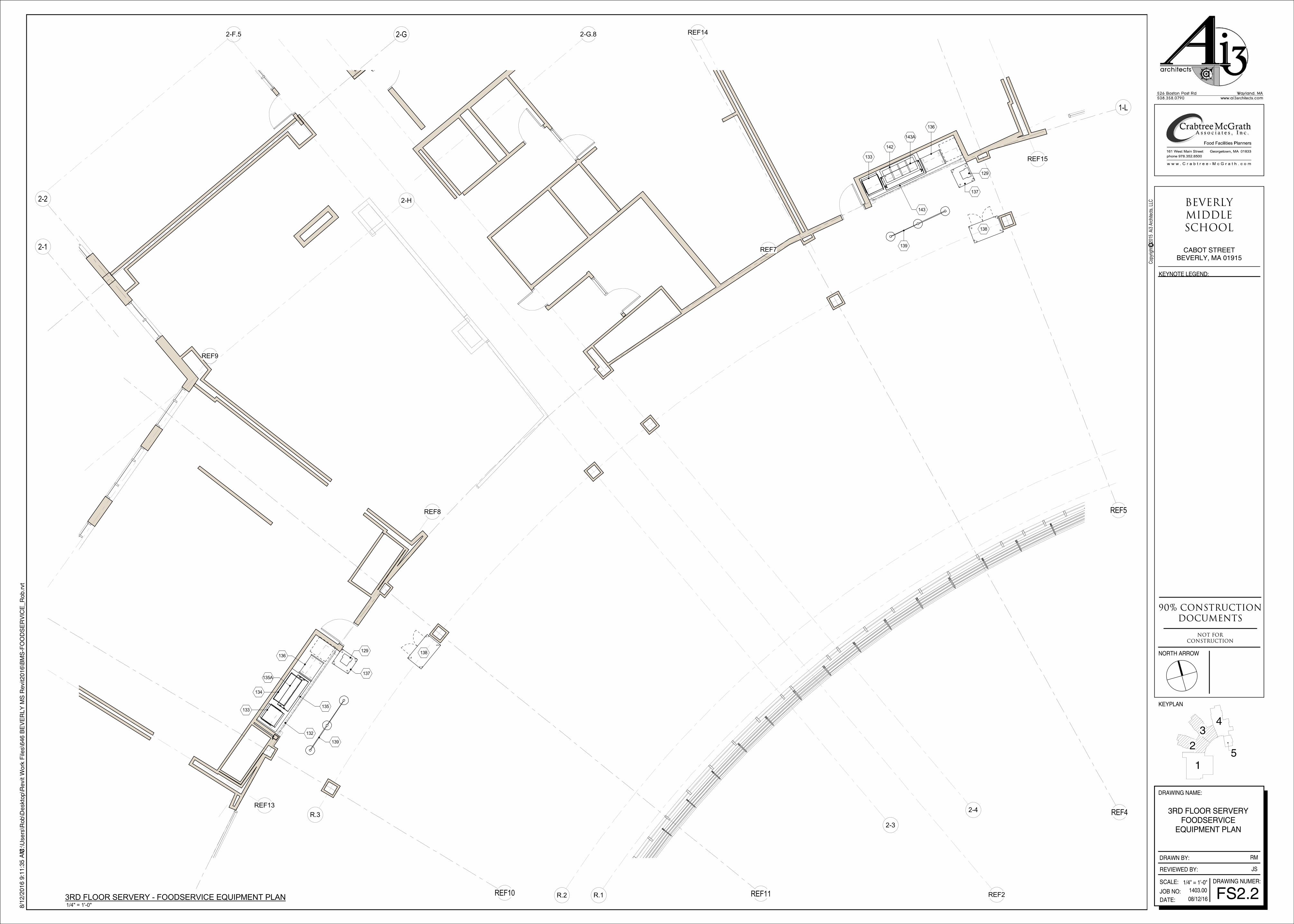
3RD FLOOR SERVERYFOODSERVICE
EQUIPMENT PLAN
FS2.2
JS
1/4" = 1'-0"
3RD FLOOR SERVERY - FOODSERVICE EQUIPMENT PLAN

3-4
3-1
3-2
3-3
3-3.8
3-H 1-L
3-3.5
REF1
3-K
3-5
3-G
4-22
3-J3-L
3-M
3-N
4-G
4-K
FS
(3) 20 A circuit - 120/1 +4"BT mounted DR by KEC
1" IW to FS
3.0 KW - 208/1 +4" BTmounted SW by KEC
1" IW to FS
(3) 20 A circuit - 120/1 +4"BT mounted DR by KEC
20 A circuit - 208/1 +4" BTmounted NEMA 6-20R by KEC
Flush-in-floor data receptacle
20 A circuit - 120/1DR flush-in-floor
1/2" H&CW +36" BTC(hose bibb by PC)
Drain in floor
24" sq floor typemop sink by PC
11.4 A - 120/1 DR +84"
11.4 A - 120/1 DR +84"
3/4" G @ 100 MBTU +12" BTC QD
(2) 8 A - 120/1 SR +48"
Blower control SW +54" w/ pilot by EC for Item 108
Ventilator light SW +54" w/ pilot by EC for Item 108
(3) 2" W manifold thru GI by PC(verify GI rough-in location)
3/4" 120°FH&CW +16" BTC
3/4" 120°FH&CW +16" BTC
1/2" HW +22" BTC
1-1/2" W +20" BTC
1/2" CW +22" BTC
(2) 20 A circuit - 120/1 +4"BT mounted DR by KEC
8.2 A - 120/1 DR +84"
13.75 A - 120/1 DR +48"
13.75 A - 120/1 DR +48"
120/1; J-box +96" for connection to buildingalarm system & equipment shutdown
5'-0"
11'-7"
2'-6"
5'-0"
8 1
/2"
EXH 875 CFM thru a 9" x 9"collar @ 0.405" SP +9'-6" AFF
Integral 3" air space stand-off
0.1 KW - 120/1 +9'-6" DFABTC from remote SW by EC
1
2
34
5
NORTH ARROW
KEYPLAN
DRAWING NAME:
DRAWN BY:
REVIEWED BY:
SCALE:
JOB NO:
DATE:
DRAWING NUMER:
KEYNOTE LEGEND:
CABOT STREETBEVERLY, MA 01915
_ÉîÉêäó
jfaaib
p`elli
Cop
yrig
ht c
201
5 A
i3 A
rchi
tect
s, L
LC
VMB=ÅçåëíêìÅíáçå
ÇçÅìãÉåíë
klq=clo
`lkpqor`qflk
1/4" = 1'-0"
8/1
2/2
016 9
:11:3
9 A
M C:\
Users
\Rob\D
eskto
p\R
evit W
ork
File
s\6
46 B
EV
ER
LY
MS
Revit2016\B
MS
-FO
OD
SE
RV
ICE
_R
ob.r
vt
1403.00
08/12/16
RM
3RD FLOOR KITCHENFOODSERVICE
EQUIPMENT ROUGH-INPLAN
FS2.3
JS
1/4" = 1'-0"
3RD FLOOR KITCHEN - FOODSERVICE EQUIPMENT ROUGH-IN PLAN
1/4" = 1'-0"FS2.3
1 Detail - Exhaust Ventilator (Item 108)

2-G
2-1
2-2
REF10 REF11
REF4
REF5
1-L
REF2
2-4
R.1R.2
R.3
REF7
REF8
2-3
2-F.5 2-G.8
2-H
REF9
REF13
REF14
REF15
13.3 A - 120/1 DR +48"
8.9 A - 120/1 DR +24"
1.1 KW - 208/1 +24" BTmounted control by KEC
16 A - 120/1 DR +24"
20 A circuit - 120/1 DR +24"
Data receptacle +24"
13.3 A - 120/1 DR +48"
1" IW to FS
6.8 A - 120/1 DR +24"
16 A - 120/1 DR +24"
20 A circuit - 120/1 DR +24"
Data receptacle +24"
FS
1
2
34
5
NORTH ARROW
KEYPLAN
DRAWING NAME:
DRAWN BY:
REVIEWED BY:
SCALE:
JOB NO:
DATE:
DRAWING NUMER:
KEYNOTE LEGEND:
CABOT STREETBEVERLY, MA 01915
_ÉîÉêäó
jfaaib
p`elli
Cop
yrig
ht c
201
5 A
i3 A
rchi
tect
s, L
LC
VMB=ÅçåëíêìÅíáçå
ÇçÅìãÉåíë
klq=clo
`lkpqor`qflk
1/4" = 1'-0"
8/1
2/2
016 9
:11:4
0 A
M C:\
Users
\Rob\D
eskto
p\R
evit W
ork
File
s\6
46 B
EV
ER
LY
MS
Revit2016\B
MS
-FO
OD
SE
RV
ICE
_R
ob.r
vt
1403.00
08/12/16
RM
3RD FLOOR SERVERYFOODSERVICE
EQUIPMENT ROUGH-INPLAN
FS2.4
JS
1/4" = 1'-0"
3RD FLOOR SERVERY - FOODSERVICE EQUIPMENT ROUGH-IN PLAN
30
33
31
32
29
28 37
39
40
23 20
21
18 18
1722
41
18
60
59 61
58
71 727070A 70B
73
74
76A
75
76
83
85A
85
78
87
8684
83
90A
90
78
87
8691
112
115113
114
1
2
34
5
NORTH ARROW
KEYPLAN
DRAWING NAME:
DRAWN BY:
REVIEWED BY:
SCALE:
JOB NO:
DATE:
DRAWING NUMER:
KEYNOTE LEGEND:
CABOT STREETBEVERLY, MA 01915
_ÉîÉêäó
jfaaib
p`elli
Cop
yrig
ht c
201
5 A
i3 A
rchi
tect
s, L
LC
VMB=ÅçåëíêìÅíáçå
ÇçÅìãÉåíë
klq=clo
`lkpqor`qflk
3/8" = 1'-0"
8/1
2/2
016 9
:11:4
1 A
M C:\
Users
\Rob\D
eskto
p\R
evit W
ork
File
s\6
46 B
EV
ER
LY
MS
Revit2016\B
MS
-FO
OD
SE
RV
ICE
_R
ob.r
vt
1403.00
08/12/16
Author
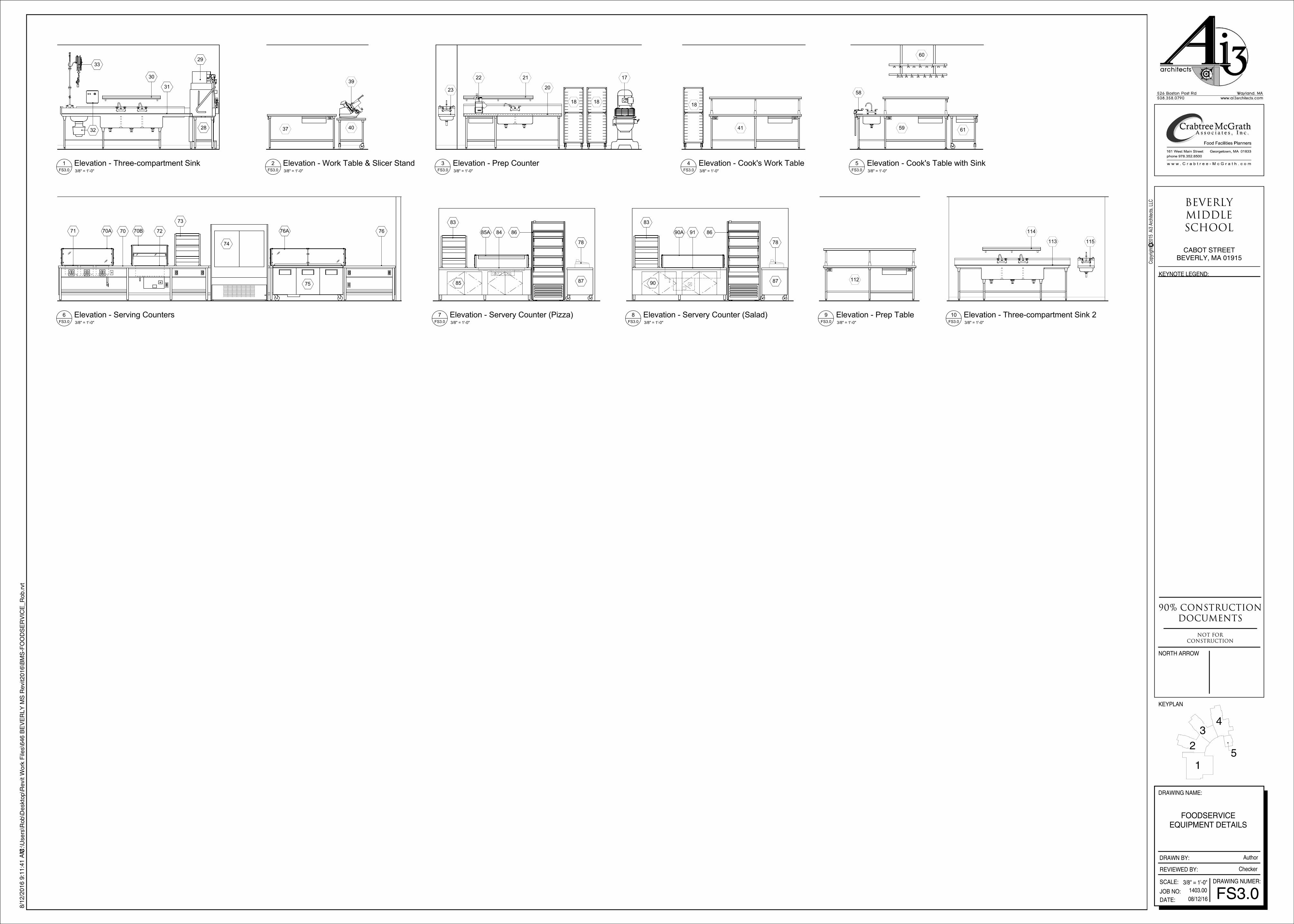
FOODSERVICEEQUIPMENT DETAILS
FS3.0
Checker
3/8" = 1'-0"FS3.0
1 Elevation - Three-compartment Sink 3/8" = 1'-0"FS3.0
2 Elevation - Work Table & Slicer Stand 3/8" = 1'-0"FS3.0
3 Elevation - Prep Counter 3/8" = 1'-0"FS3.0
4 Elevation - Cook's Work Table 3/8" = 1'-0"FS3.0
5 Elevation - Cook's Table with Sink
3/8" = 1'-0"FS3.0
6 Elevation - Serving Counters 3/8" = 1'-0"FS3.0
7 Elevation - Servery Counter (Pizza) 3/8" = 1'-0"FS3.0
8 Elevation - Servery Counter (Salad) 3/8" = 1'-0"FS3.0
9 Elevation - Prep Table 3/8" = 1'-0"FS3.0
10 Elevation - Three-compartment Sink 2


