International Journal of Computer Applications (0975 – 8887)
Volume 156 – No 1, December 2016
12
Free Vibration Analysis of Stiffened Laminated
Composite Plates
Arafa El-Helloty Associated Professor of structures,
Department of Civil Engineering, Al-Azhar University,
ABSTRACT
Stiffened Laminated composite plates are widely used in the
aerospace, civil, marine, and automotive industries due to their
high specific stiffness and strength, excellent fatigue resistance,
long durability and many other superior properties compared to
ordinary plates. In this paper, the effect of stiffener
configuration, number of layers and boundary conditions on the
free vibration response of stiffened laminated composite plates
are examined with respect to natural frequencies and mode
shapes. Six rectangular stiffeners configurations models are
used with two types of boundary conditions which are simply
and clamped supported. Comparative study is conducted to
investigate the effect of stiffener configuration, number of
layers and boundary conditions on the free vibration response of
stiffened laminated composite plates using the finite element
system ANSYS16.
Keywords
Laminated, composite plate, stiffener, cross-ply, number of
layers, modal analysis, frequency.
1. INTRODUCTION Stiffened laminated composite plates are extensively used in the
construction of aerospace, civil, marine, automotive and other
high performance structures due to their high strength to
weight, stiffness to weight ratios and modulus, excellent
fatigue resistance, long durability and many other superior
properties compared to ordinary plates. The high specific
strength and specific stiffness which are the bases of the
superior structural performance of composite materials provide
the composite materials many application choices. The correct
and effective use of such laminates require more complex
analysis in order to predict accurately the static and dynamic
response of these structures under external loading. Most of the
structures generally work under severe dynamic loading and
different constrained conditions during their service life. To use
stiffened laminated composite plates efficiently, an accurate
knowledge of vibration characteristics is essential.
Problems are often occurred in structures due to vibrations and
it is important to prevent such problems because it can cause
structural fatigue and damage. Therefore, determination of the
natural frequency of the stiffened laminated composite plates is
a practical demand when the structures are subjected to periodic
exciting loads. To assessing the natural frequency of the
stiffened laminated composite plates, the modal analysis is
required to obtain the data that are required to avoid resonance
in structures affected by external periodic dynamic loads. Using
the finite element method, many researchers have been devoted
to the analysis of vibrations and dynamics, buckling and post
buckling behavior, failure and damage analysis of laminated
composite plates [1-12]. The finite element method is especially
versatile and efficient for the analysis of complex structural
behavior of laminated composite plates.
The vibration behavior of laminated composite plates without
stiffener has been studied by extensive researchers[1-
3,5,7,8,11,12]. Also, a number of analytical and numerical
models for the free vibration response of stiffened laminated
composite plates have been presented in the literature. R.
Rikards et al. (2001) [9] developed of triangular finite element
for buckling and vibration analysis of laminated composite
stiffened shells. For the laminated shell, an equivalent layer
shell theory was employed and the first-order shear deformation
theory including extension of the normal line was used.
Numerical examples were presented and laminated composite
plate with one stiffener was considered to show the accuracy
and convergence characteristics of the element. G. Qing et al. (2006)[4] developed a novel mathematical model for free
vibration analysis of stiffened laminated plates based on the
semi-analytical solution of the state-vector equation theory. The
transverse shear deformation and the rotary inertia were also
considered in the model and the thickness of plate and the
height of stiffeners were not restricted. several numerical
examples that were plates with two stiffeners in one direction
and a plate with four stiffeners in two orthogonal directions
were analyzed and the convergence of all examples was tested.
T. I. Thinh and N. N. Khoa (2008)[10] presented a new 9-noded
rectangular stiffened plat element for the vibration analysis of
stiffened laminated plates which was based on Mindlin's
deformation plate theory. The stiffened plate element was a
combination of basic rectangular element and beam bending
component. Some problems on free vibration analysis of
stiffened laminated composite plates that were made of
graphite/ epoxy and glass/polyester with three stiffeners in one
direction were analyzed with the presented element. L.
Yanhong et al. (2014)[6] developed a three-dimensional semi-
analytical model for the free vibration analysis of stiffened
composite laminates with interfacial imperfections that were
based on the state space method and the linear spring layer
model. Several numerical examples which were plates with two
stiffeners in one direction were carried out to demonstrate an
excellent predictive capability of this model in assessing the
natural frequencies and vibration modes.
Therefore, the aim of this paper is to study the effect of stiffener
configuration, number of layers and boundary conditions on the
free vibration response of stiffened laminated composite plates
using the finite element system ANSYS16. Simply and clamped
supported stiffened laminated composite plates are considered
with symmetric cross-ply laminates arrangements and the
modal analysis is carried out.
2. MODAL ANALYSIS The modal analysis is used to determine the vibration
characteristics of a structure which it are natural frequencies
and mode shapes while it is being designed. It also can be a
starting point for another dynamic analysis such as a transient
dynamic analysis, a harmonic response analysis, or a spectrum
analysis. The dynamic behavior of the structure is defined by a

International Journal of Computer Applications (0975 – 8887)
Volume 156 – No 1, December 2016
13
special frequency spectrum which consisting of an infinite
number of natural frequencies and mode shapes which can be
found by knowing the geometrical shape, mass distribution,
stiffness and boundary conditions of the structures. In general,
the equation of motion for a linear dynamic system is [1-12]:
M u + C u + K u = F t (1)
Where:
[M] = mass matrix, [C] = damping matrix, [K] = stiffness
matrix, {F(t)} = time varying load vector, u = nodal
acceleration vector, u = nodal velocity vector and u =
nodal displacement vector.
For free vibration the equation (1) becomes:
M u + C u + K u = 0 (2)
When undamped linear structures are initially displaced into a
certain shape, they will oscillate indefinitely with the same
mode shape but varying amplitudes. The oscillation shapes are
called the mode shapes and the corresponding frequencies are
called natural frequencies. For undamped linear structures, the
equation (2) reduces to:
M u + K u = 0 (3)
With no externally applied loads, the structure is assumed to
vibrate freely in a harmonic form which is defined by:
U t = φ sin wt + θ (4)
which leads to the eigenvalue problem as:
K − w2 M φ = 0 (5)
Where w is the natural frequency and φ is the corresponding
mode shape of the structure.
3. NUMERICAL EXAMPLE To study the effect of stiffener configuration, number of layers
and boundary conditions on the free vibration response of
stiffened laminated composite plates, the modal analysis of a
laminated composite plate without and with stiffeners is
considered with dimensions 1.0 m x 1.0 m and thickness h = 1
mm as shown in Fig. 1. Six rectangular stiffeners configurations
models are used in the numerical studies with dimension 1.0 m
x 0.10 m and thickness h = 1 mm as shown in Fig. 1 where
model 1 has one stiffener in one direction, model 2 has two
stiffeners in one direction, model 3 has three stiffeners in one
direction, model 4 has four stiffeners in one direction, model 5
has two stiffeners in two orthogonal directions and model 6 has
four stiffeners in two orthogonal directions.
In this study, two different boundary conditions which are
simply supported and clamped supported on all four sides are
considered. Laminates and stiffeners are composite plates
consisting of four, six, eight and ten orthotropic plies of the
same material and equal thickness with the overall thickness
kept constant. Symmetric cross-ply laminates arrangements
with simple and clamped boundary conditions are considered. A
Epoxy/ Carbon composite material (UD 395 Gpa Prepreg) from
ANSYS16 composite materials library is used and the materials
properties are given as E1 = 209 GPa, E2 = 9.45 GPa, E3 = 9.45
GPa, G12 = 5.5 GPa, G13= 5.0 GPa, G23 = 3.9 GPa, ν12= 0.27,
ν13= 0.27 , ν23= 0.4 and ρ = 1540 kg/m3 for Young’s modulus,
shear modulus, Poisson’s ratio and density respectively.
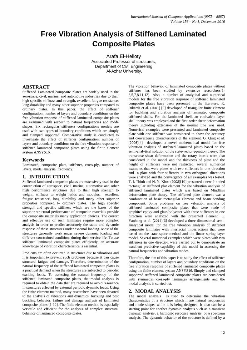
3.1 Method of analysis The modal analysis has been done by 8-node SHELL281
element in finite element system ANSYS16. The SHELL281 as
shown in Fig. 2 is a eight-node element with six degrees of
freedom at each node that are translations in the x, y, and z
axes, and rotations about the x, y, and z-axes. The element is
suitable for analyzing thin to moderately- thick shell structures and it is appropriate for linear, large rotation and/ or large strain
nonlinear applications. SHELL281 may be used for layered
applications for modeling laminated composite shells or sandwich construction and the accuracy in modeling composite shells is governed by the first order shear
deformation theory.
Fig. 1: Plates without and with stiffeners
xo = Element x-axis if element orientation is not provided.
x = Element x-axis if element orientation is provided.
International Journal of Computer Applications (0975 – 8887)
Volume 156 – No 1, December 2016
14
Fig. 2: 8-node SHELL281 element
3.2 Numerical verification. To verify the analysis and results obtained in this study by the
finite element system ANSYS16, A Free vibration analysis of
ten layers simply supported laminated composite square plate is
considered as reported in reference [8] by M. Reddy et al. The
dimension of plate is 0.2 m x 0.2 m and the orientation of layers
of plate is symmetry which is [0°/90°/0°/90°/0°]s and each layer
has equal thickness with overall thickness of plate 0.00269 m.
The material is considered to be T300/934 CFRP with the
mechanical properties as: E1 = 120 GPa, E2 =7.9 GPa, G12 = 5.5
GPa, ν12= 0.33 and ρ = 1580 kg/m3 for Young’s modulus, shear
modulus, Poisson’s ratio and density respectively.
The modal analysis is done for plate and the first natural
frequency is carried out and compared with that obtained by M.
Reddy et al. As shown in Table 1, the result obtained by finite
element system ANSYS16 is in very good agreement with the
result that is obtained by M. Reddy et al.
Table 1: Verification of analysis and results
Reference. Natural frequency. HZ
M. Reddy et al. 302.05
ANSYS16 302.8
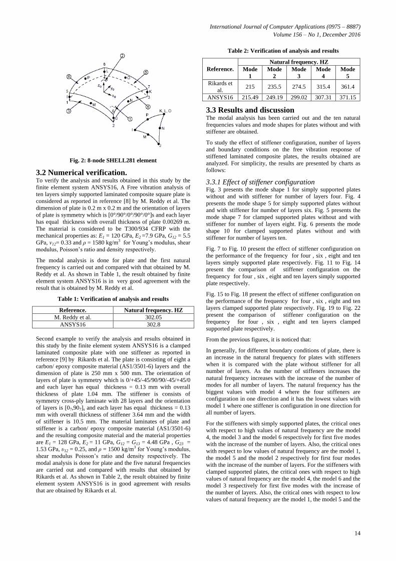
Second example to verify the analysis and results obtained in
this study by the finite element system ANSYS16 is a clamped
laminated composite plate with one stiffener as reported in
reference [9] by Rikards et al. The plate is consisting of eight a
carbon/ epoxy composite material (AS1/3501-6) layers and the
dimension of plate is 250 mm x 500 mm. The orientation of
layers of plate is symmetry which is 0/+45/-45/90/90/-45/+45/0
and each layer has equal thickness = 0.13 mm with overall
thickness of plate 1.04 mm. The stiffener is consists of
symmetry cross-ply laminate with 28 layers and the orientation
of layers is [07,907]s and each layer has equal thickness = 0.13
mm with overall thickness of stiffener 3.64 mm and the width
of stiffener is 10.5 mm. The material laminates of plate and
stiffener is a carbon/ epoxy composite material (AS1/3501-6)
and the resulting composite material and the material properties
are E1 = 128 GPa, E2 = 11 GPa, G12 = G13 = 4.48 GPa , G23 =
1.53 GPa, υ12 = 0.25, and ρ = 1500 kg/m3 for Young’s modulus,
shear modulus Poisson’s ratio and density respectively. The
modal analysis is done for plate and the five natural frequencies
are carried out and compared with results that obtained by
Rikards et al. As shown in Table 2, the result obtained by finite
element system ANSYS16 is in good agreement with results
that are obtained by Rikards et al.
Table 2: Verification of analysis and results
Reference.
Natural frequency. HZ
Mode
1
Mode
2
Mode
3
Mode
4
Mode
5
Rikards et
al. 215 235.5 274.5 315.4 361.4
ANSYS16 215.49 249.19 299.02 307.31 371.15
3.3 Results and discussion The modal analysis has been carried out and the ten natural
frequencies values and mode shapes for plates without and with
stiffener are obtained.
To study the effect of stiffener configuration, number of layers
and boundary conditions on the free vibration response of
stiffened laminated composite plates, the results obtained are
analyzed. For simplicity, the results are presented by charts as
follows:
3.3.1 Effect of stiffener configuration Fig. 3 presents the mode shape 1 for simply supported plates
without and with stiffener for number of layers four. Fig. 4
presents the mode shape 5 for simply supported plates without
and with stiffener for number of layers six. Fig. 5 presents the
mode shape 7 for clamped supported plates without and with
stiffener for number of layers eight. Fig. 6 presents the mode
shape 10 for clamped supported plates without and with
stiffener for number of layers ten.
Fig. 7 to Fig. 10 present the effect of stiffener configuration on
the performance of the frequency for four , six , eight and ten
layers simply supported plate respectively. Fig. 11 to Fig. 14
present the comparison of stiffener configuration on the
frequency for four , six , eight and ten layers simply supported
plate respectively.
Fig. 15 to Fig. 18 present the effect of stiffener configuration on
the performance of the frequency for four , six , eight and ten
layers clamped supported plate respectively. Fig. 19 to Fig. 22
present the comparison of stiffener configuration on the
frequency for four , six , eight and ten layers clamped
supported plate respectively.
From the previous figures, it is noticed that:
In generally, for different boundary conditions of plate, there is
an increase in the natural frequency for plates with stiffeners
when it is compared with the plate without stiffener for all
number of layers. As the number of stiffeners increases the
natural frequency increases with the increase of the number of
modes for all number of layers. The natural frequency has the
biggest values with model 4 where the four stiffeners are
configuration in one direction and it has the lowest values with
model 1 where one stiffener is configuration in one direction for
all number of layers.
For the stiffeners with simply supported plates, the critical ones
with respect to high values of natural frequency are the model
4, the model 3 and the model 6 respectively for first five modes
with the increase of the number of layers. Also, the critical ones
with respect to low values of natural frequency are the model 1,
the model 5 and the model 2 respectively for first four modes
with the increase of the number of layers. For the stiffeners with
clamped supported plates, the critical ones with respect to high
values of natural frequency are the model 4, the model 6 and the
model 3 respectively for first five modes with the increase of
the number of layers. Also, the critical ones with respect to low
values of natural frequency are the model 1, the model 5 and the

International Journal of Computer Applications (0975 – 8887)
Volume 156 – No 1, December 2016
15
model 2 respectively for first four modes with the increase of
the number of layers.
Fig. 3: Mode shape 1 for simply supported plates without and with stiffener for number of layers four

International Journal of Computer Applications (0975 – 8887)
Volume 156 – No 1, December 2016
16
Fig. 4: Mode shape 5 for simply supported plates without and with stiffener for number of layers six

International Journal of Computer Applications (0975 – 8887)
Volume 156 – No 1, December 2016
17
Fig. 5: Mode shape 7 for clamped supported plates without and with stiffener for number of layers eight

International Journal of Computer Applications (0975 – 8887)
Volume 156 – No 1, December 2016
18
Fig. 6: Mode shape 10 for clamped supported plates without and with stiffener for number of layers ten

International Journal of Computer Applications (0975 – 8887)
Volume 156 – No 1, December 2016
19
Fig. 7: Effect of stiffener configuration on the performance
of the frequency for four layers simply supported plate
Fig. 8: Effect of stiffener configuration on the performance
of the frequency for six layers simply supported plate
Fig. 9: Effect of stiffener configuration on the performance
of the frequency for eight layers simply supported plate
Fig. 10: Effect of stiffener configuration on the performance
of the frequency for ten layers simply supported plate
Fig. 11: Comparison of stiffener configuration on the
frequency of four layers simply supported plate
Fig. 12: Comparison of stiffener configuration on the
frequency of six layers simply supported plate
Fig. 13: Comparison of stiffener configuration on the
frequency of eight layers simply supported plate
Fig. 14: Comparison of stiffener configuration on the
frequency of ten layers simply supported plate

International Journal of Computer Applications (0975 – 8887)
Volume 156 – No 1, December 2016
20
Fig. 15: Effect of stiffener configuration on the performance
of the frequency for four layers clamped supported plate
Fig. 16: Effect of stiffener configuration on the performance
of the frequency for six layers clamped supported plate
Fig. 17: Effect of stiffener configuration on the performance
of the frequency for eight layers clamped supported plate
Fig. 18: Effect of stiffener configuration on the performance
of the frequency for ten layers clamped supported plate
Fig. 19: Comparison of stiffener configuration on the
frequency of four layers clamped supported plate
Fig. 20: Comparison of stiffener configuration on the
frequency of six layers clamped supported plate
Fig. 21: Comparison of stiffener configuration on the
frequency of eight layers clamped supported plate
Fig. 22: Comparison of stiffener configuration on the
frequency of ten layers clamped supported plate

International Journal of Computer Applications (0975 – 8887)
Volume 156 – No 1, December 2016
21
3.3.2 Effect of number of layers. Fig. 23 to Fig. 25 present effect of number of layers on the
performance of frequency for simply supported plate for modes
1, 2, 3, 4, 9 and 10 respectively. Fig. 26 to Fig. 28 present
comparison of number of layers on the performance of
frequency for simply supported plate for modes 1, 2, 3, 4, 9 and
10 respectively.
Fig. 29 to Fig. 31 present effect of number of layers on the
performance of frequency for clamped supported plate for
modes 1, 2, 3, 4, 9 and 10 respectively. Fig. 32 to Fig. 34
present comparison of number of layers on the performance of
frequency for clamped supported plate for modes 1, 2, 3, 4, 9
and 10 respectively.
Fig. 23: Effect of number of layers on the performance of
frequency for simply supported plate for modes 1 and 2
Fig. 24: Effect of number of layers on the performance of
frequency for simply supported plate for modes 3 and 4
Fig. 25: Effect of number of layers on the performance of
frequency for simply supported plate for modes 9 and 10
Fig. 26: Comparison of number of layers on the frequency
of simply supported plate for modes 1 and 2
Fig. 27: Comparison of number of layers on the frequency
of simply supported plate for modes 3 and 4
Fig. 28: Comparison of number of layers on the frequency
of simply supported plate for modes 9 and 10
Fig. 29: Effect of number of layers on the performance of
frequency for clamped supported plate for modes 1 and 2

International Journal of Computer Applications (0975 – 8887)
Volume 156 – No 1, December 2016
22
Fig. 30: Effect of number of layers on the performance of
frequency for clamped supported plate for modes 3 and 4
Fig. 31: Effect of number of layers on the performance of
frequency for clamped supported plate for modes 9 and 10
Fig. 32: Comparison of number of layers on the frequency
of clamped supported plate for modes 1 and 2
Fig. 33: Comparison of number of layers on the frequency
of clamped supported plate for modes 3 and 4
Fig. 34: Comparison of number of layers on the frequency
of clamped supported plate for modes 9 and 10
From the previous figures, it is noticed that:
In generally, for different boundary conditions of plate, as the
number of layers increases there is an increase in the natural
frequency for plates with stiffeners when it is compared with
the plate without stiffener with the increase of the number of
modes. For different boundary conditions of plate, as the
number of layers increases there is no much variation in the
natural frequency for all models with the increase of the number
of modes. The natural frequency has the biggest values when
the number of layers equals four for all models with the
increase of the number of modes.
3.3.2 Effect of boundary conditions. Fig. 35 to Fig. 38 present the comparison of stiffener
configuration on the frequency for simply and clamped
supported plate for modes 1, 2, 3 and 10 respectively.
Fig. 35: Comparison of stiffener configuration on the
frequency of simply and clamped supported plate for
mode1
Fig. 36: Comparison of stiffener configuration on the
frequency of simply and clamped supported plate for mode
2

International Journal of Computer Applications (0975 – 8887)
Volume 156 – No 1, December 2016
23
Fig. 37: Comparison of stiffener configuration on the
frequency of simply and clamped supported plate for mode
3
Fig. 38: Comparison of stiffener configuration on the
frequency of simply and clamped supported plate for mode
10
From the previous figures, it is noticed that:
In general, for simply and clamped supported stiffened plates,
there is an increase in the natural frequency for plates with
stiffeners when it is compared with the plate without stiffener
with the increase of the number of modes for all models and all
number of layers. The natural frequency for stiffened plates
with clamped supported is higher than that for stiffened plates
with simply supported with the increase of the number of
modes for all models and all number of layers. The natural
frequency has the biggest values with clamped supported
stiffened plates when the number of layers equals four for all
models with the increase of the number of modes.
4. CONCLUSIONS In this paper, the modal analysis of stiffened laminated
composite plates has been done to study the effect of stiffener
configuration, number of layers and boundary conditions on the
free vibration response of stiffened laminated composite plates.
From the results reported herein, the following conclusions are
obtained:
1. Presence, arrangement and configuration of stiffeners have
important effects on the free vibration response of stiffened
laminated composite plates which should be considered in
the design of stiffened laminated composite plates.
2. As the number of stiffener increase the natural frequency
increase with the increase of the number of modes for all
number of layers.
3. The natural frequency is higher with model four where the
four stiffeners are configuration in one direction than that
with other models with the increase of the number of
modes for all number of layers.
4. Boundary conditions of plates have a significant influence
on the free vibration response of stiffened laminated
composite plates where the natural frequency for clamped
supported are higher than that for the simply supported
with the increase of the number of modes for all models
and all number of layers.
5. As the number of layers increases there is no much
variation in the natural frequency for all models with the
increase of the number of modes.
5. REFERENCES [1] A.S. Ashour, 2009.The free vibration of symmetrically
angle-ply laminated fully clamped skew plates. Journal of
Sound and Vibration, 323, 444–450.
[2] A. K. Sharma and N. D. Mittal, 2013. Free vibration
analysis of laminated composite plates with elastically
restrained edges using FEM. Cent. Eur. J. Eng., 3(2), 306-
315.
[3] B. S. Reddy, M. S. Reddy and V. Nageswara, 2013.
Vibration analysis of laminated composite plates using
design of experiments approach. International Journal of
Scientific Engineering and Technology, Volume No.2,
Issue No.1, pp. 40-49.
[4] G. Qing, J. Qiu and Y. Liu, 2006. Free vibration analysis
of stiffened laminated plates. International Journal of
Solids and Structures, 43, 1357–1371.
[5] H. K. Bhardwaj, J. Vimal and A. K. Sharma, 2015. Study
of free vibration analysis of laminated composite plates
with triangular cutouts. Engineering Solid Mechanics, 3,
43-50.
[6] L. Yanhong, L. Dinghe and W. Yanli, 2014. Free vibration
analysis of stiffened composite laminated plates with
interfacial imperfections. IAENG International Journal of
Applied Mathematics, 44:1, IJAM.
[7] M. Ganapathi , A. Kalyani, B. Mondal and T. Prakash,
2009. Free vibration analysis of simply supported
composite laminated panels. Composite Structures, 90,
100–103.
[8] M. S. Reddy, B. S. Reddy, V. N. Reddy and S.
Sreenivasulu, 2012. Prediction of natural frequency of
laminated composite plates using artificial neural
networks. Engineering, 4, 329-337.
[9] R. Rikards, A. Chate and O. Ozolinsh, 2001. Analysis for
buckling and vibrations of composite stiffened shells and
plates. Composite Structures, 51, 361-370.
[10] T. I. Thinh and N. N. Khoa, 2008. Free vibration analysis
of stiffened laminated plates using a new stiffened
element. Technische Mechanik, Band 28, Heft 3-4, 227-
236.
[11] U. Topal and Uzman, 2008. Frequency optimization of
laminated composite angle-ply plates with circular hole.
Materials and Design 29, 1512–1517.
[12] U. Topal and Uzman, 2009. Frequency optimization of
laminated skew plates. Materials and Design 30, 3180–
3185.
IJCATM : www.ijcaonline.org


