1
FLIGHTZOOMER 1.5
FUNCTIONAL ASPECTS

2
1 Contents 2 Disclaimer .................................................................................................................................................. 4
3 FlightZoomer in a nutshell ......................................................................................................................... 4
4 Functional aspects ..................................................................................................................................... 5
4.1 Overview ............................................................................................................................................ 5
4.2 he apps .............................................................................................................................................. 7
4.3 How does it work ............................................................................................................................... 8
4.4 System requirements ........................................................................................................................ 8
4.5 Operation scenarios .......................................................................................................................... 9
4.5.1 Normal operation ...................................................................................................................... 9
4.5.2 Normal operation, multiple groundstations.............................................................................. 9
4.5.3 Replay file operation ............................................................................................................... 10
4.5.4 Simulated operation ................................................................................................................ 10
4.5.5 Simulated operation, with joystick .......................................................................................... 10
4.5.6 Live position ............................................................................................................................. 11
4.6 Network connectivity ...................................................................................................................... 11
4.6.1 Principle ................................................................................................................................... 11
4.6.2 Control the preferred network ................................................................................................ 11
4.6.2.1 FlightZoomer Sensorics-app ................................................................................................ 11
4.6.2.2 FlightZoomer Groundstation-app ........................................................................................ 12
4.7 State Model ..................................................................................................................................... 12
4.8 Sensor data via MAVLink ................................................................................................................. 13
4.8.1 MAVLink requirements ............................................................................................................ 13
4.9 Navigation data ............................................................................................................................... 14
4.9.1 Navigation aid .......................................................................................................................... 16
4.9.2 Airport ...................................................................................................................................... 17
4.9.3 Runway .................................................................................................................................... 17
4.10 System accuracy .............................................................................................................................. 19
4.10.1 Time accuracy (lag time) .......................................................................................................... 20
4.10.2 Position accuracy ..................................................................................................................... 22
4.10.3 Altitude accuracy ..................................................................................................................... 24
4.10.4 Turn indication accuracy .......................................................................................................... 25
4.10.5 Compass accuracy ................................................................................................................... 26
4.10.6 Attitude accuracy ..................................................................................................................... 27
4.11 Units of measurement ..................................................................................................................... 28
5 Appendix .................................................................................................................................................. 29

3
5.1 Glossary ........................................................................................................................................... 29

4
2 Disclaimer
While FlightZoomer offers fantastic features, the following operation rules are strictly to be followed:
- The system is intended for hobby usage.
- Be familiar with the operation of RC aircraft having 1kg flying weight or more.
- Use FlightZoomer only aboard a proved combination of RC equipment, airframe, flight controller,
motors, propeller, battery and ESCs.
- Operate FlightZoomer strictly within the safety boundaries of any other used components.
- Operate FlightZoomer strictly within the boundaries of any local regulatory requirement.
- Fully respect any disclaimer and safety note which is associated with any other used component.
3 FlightZoomer in a nutshell
FlightZoomer is a smartphone based system which can be used to navigate, track, control and record the
flight of remote controlled model aircraft, especially fixed wing planes and multicopters. A special emphasis
is laid on the implementation of the systems and procedures of a real airliner cockpit.
FlightZoomer is supplementary to an existing setup consisting of an RC aircraft (which can be a multicopter
or an airplane), a flight controller and an RC transmitter.
There are many use cases covered with the first version of FlightZoomer:
- Transmission of sensor data from an onboard smartphone to a ground-based smartphone
groundstation via cellular network: so your range is virtually unlimited!
- The source of sensor data preferably is the flight controller (connected via MAVLink): Get the
highest available accuracy!
- The phone offers an additional sensor set which can be used (though by far not as accurate):
Get a fully redundant second sensor stack!
- Provide a display to the pilot showing the position of the aircraft on a moving map: so you can
navigate, guide or even track lost copters!
- Display speed, altitude and attitude to the pilot: so you get the information like in a real cockpit!
- Allowing the pilot to navigate the aircraft based on self-created flightplans: prepare, plan and
execute routes like real pilots do (according to instrument flight rules)!
- Even scale RC aircraft usually just remind visually on their originals but are flown with systems that
bare no similarity with their real world counterparts: operate your RC aircraft using an avionics
suite that reproduces the cockpit of a real Boeing 787 Dreamliner!
- Synthetic voice to guide the pilot along the flightplan: experience guidance from a simulated co-
pilot!
- Allowing to navigate based on a radio navigation aid simulation: create your own airspace with
airports and navigation aids!
- Instrument Landing System (ILS) offering the full set of real world instruments including the
beeping at the outer, middle and inner markers: capture and follow the glideslope performing
precision approaches with your RC aircraft!
- Let the camera of the onboard device record images or videos of the flight: make use of the stuff a
smartphone brings with it!

5
- Provide extensive flight telemetry/logging capabilities: dig into masses of data for post flight
analysis!
- Flight replay feature: show your friends at any time, how your cockpit looked during a flight!
- Flight simulation feature: induce simulated flight movements (altitude, course, speed and vertical
speed) to explore the capabilities of the groundstation in your living room!
- Testpilot feature: let the system automatically measure some of the required flight performance
parameters!
4 Functional aspects
4.1 Overview
The following diagram shows the control loop over all involved elements:
FlightZoomer consists of three components:
1. The FlightZoomer Sensorics device. This is a Windows Phone device, mounted on a RC aircraft. It is
connected via MAVLink to the flight controller.
2. The relay server. This is a PC at home (or alternatively in the cloud) on which the
FlightZoomer Relay Server application runs. The relay server connects the FlightZoomer Sensorics
and the FlightZoomer Groundstation devices over the Internet.
Multicopter or another aircraft with a flight controller
Mounted on the multicopter: the sensor device with the
FlightZoomer Sensorics-app.
A Windows computer at home (with internet connection),
where the FlightZoomer Relay Server application runs.
Another smartphone running the FlightZoomer
Groundstation-app
You as a pilot of the RC aircraft!
And, last but not least, a RC transmitter for
controlling the aircraft
1
3
2
6
3. The FlightZoomer Groundstation device. This is also a Windows Phone device, which is used as
display and touchscreen interface for the pilot.
The principle is very simple: Overall FlightZoomer is a pure software solution that fully relies on off-the-
shelf hardware.
There is the FlightZoomer Sensorics app. This app runs on a smartphone device, which is mounted on an RC
aircraft. The app receives all flight parameters in real time from the flight controller via the MAVLink
interface and transmits them via cellular network to the Relay server, which then forwards the data in near
real time to a second smartphone device, which runs the FlightZoomer Groundstation app and acts as a
groundstation.

7
4.2 he apps

8
4.3 How does it work
A detailed functional description would exceed the reasonable scope of this document. Therefore the
following diagram shall just show a bunch of ingredients (technologies/algorithms/formulas), which have
been used or have been under consideration for FlightZoomer:
4.4 System requirements
- FlightZoomer is a sole software solution which currently runs on Windows Phone (the apps) and
Windows 7 or higher (the relay server).
- The devices, on which the software runs, are off-the-shelf devices.
- The typical latency of FlightZoomer is not bad (0.03 to 0.13 seconds, on average about 0.08
seconds) but…
- Occasional latency spikes prohibit controlling the RC aircraft without additional stabilization. Thus
the RC aircraft must be equipped with a MAVLink based flight controller (APM, Pixhawk, AUAV
X2,…). The flight controller must offer predictable and reliable flight characteristics.
- The onboard device can be mounted on the aircraft in any attitude (there is a geometry capturing
sequence to measure the actual attitude).

9
4.5 Operation scenarios
There are many operation scenarios, which serve different purposes and use cases.
4.5.1 Normal operation
During normal operation the sensor device transmits sensor and location data to the relay server. The data
is then fed forward to the groundstation.
In the opposite direction certain commands can be sent from the groundstation to the sensor device.
The sensor and location data are automatically written into a flight-logfile on the relay server as soon as the
system switches to flight locked (armed) mode (see 4.7).
4.5.2 Normal operation, multiple groundstations
Supplementary to the normal operation scenario, additional groundstations can connect to the relay
server. This allows observing flights from multiple devices. So you can you onboard your wife or your
friends when taking off with your RC aircraft! Regardless where they are on the world!
Sensor device
Ground-
station
Sensor device
Ground-
station

10
4.5.3 Replay file operation
The flight logfiles, which have been created while flying, can be used later to replay the flight in real time.
This allows repeating earlier flights for analysis, training or demonstration purposes.
4.5.4 Simulated operation
Beside the option to replay logfiles from earlier flights, the flight parameters (location, speed, course and
altitude) can also be generated directly by providing these parameters on the relay server GUI. This allows
to simulate very precise flight movements again for training purposes and system acquainting.
4.5.5 Simulated operation, with joystick
The input for the flight simulation can also come from standard joystick, which is connected to the relay
server. This allows to train and inspect the features of the groundstation nearly as realistic as flying with the
real model.
Sensor device
Ground-
station
Sensor device
Ground-
station Pos, Spd, Crs
entered via GUI
Sensor device
Ground-
station

11
4.5.6 Live position
The last operation scenario allows to observe and track the position of the sensor device directly on the
relay server. Again a feature to impress those, who stayed at home. This capability is also available during
normal operation.
4.6 Network connectivity
4.6.1 Principle
Between both apps and the relay server bi-directional UDP connections are established. While the relay
server is just listening for (and responding to) incoming messages, the two apps need to initiate the
communication.
The user therefore needs to provide UDP connectivity between the phones and the PC where the relay
server runs. This might involve usage of DSN services, firewall configuration and port forwarding
configuration. How this is actually is done is described in the chapter Prepare the FlightZoomer Relay Server
in the Installation document.
The backward channel from the relay server to the smartphone apps does not need to be configured,
because the relay server just responds to the sender of the incoming messages.
The UDP port number on which the relay server is listening for incoming messages is statically configured
with 57778. Both phones connect to this port and are differentiated by the relay server based on their
respective endpoint.
4.6.2 Control the preferred network
4.6.2.1 FlightZoomer Sensorics-app
The FlightZoomer Sensorics-app allows to define whether the preferred connectivity would be via cellular
or WIFI network interfaces (switching on the connection either with the CELULAR or the WIFI button).
Setting the network preference just means that the operating system will pick the preferred network
interface type if more than one are available. Without preference the operating system would just pick the
best available network. And if only one network is available, the device will establish connectivity using that
network interface in all cases. Independent of the selected network interface, the FlightZoomer Sensorics
app will display which network interface type is being used.
Sensor device
Ground-
station
12
While flying, cellular network connectivity should be selected as preference. The WIFI option on the other
hand allows setting up local communication between the sensor device and the relay server at home
without burdening the mobile data plan. This can be used for testing purposes and to download videos
from the device (if FlightZoomer Sensorics is used to record videos, the only way to download them is the
built-in download functionality).
4.6.2.2 FlightZoomer Groundstation-app
The FlightZoomer Groundstation-app will always automatically connect to the relay server with cellular
network preference. There is no option to choose the network type preference.
4.7 State Model
The whole system has three end-to-end modes:
- Idle
- Connected
- Flight Lock
These three modes reflect the state of the communication between the FlightZoomer components. In all
three modes the source of the transmitted sensor data can either be the MAVLink, the phone’s sensors or
both.
Idle-mode:
The app on either smartphone has been started but not yet connected to the relay server.
Connected-mode:
The connection from either of the smartphones to the relay server has been established. In this state all the
sensor data is already passed from the sensor device to the groundstation device. The whole flight
preparations can take place in this mode.
Flight Lock-mode:
Immediately before taking off, the devices need to be switched into the Flight Lock-mode. This prevents
further user input on the touchscreen of the FlightZoomer Sensorics device and starts recording the flight
data on the relay server. In addition the camera starts recording a video or taking images (if any of the two
options is activated, see Error! Reference source not found.).
If the sensor device is mated with the flight controller (which is typically the case) the Flight Lock-mode
goes along with the armed state of the aircraft’s throttle. These two states are kept in sync automatically in
both directions:
- Whenever the flight controller is brought into armed state (e.g. via RC transmitter), the
FlightZoomer Sensorics-app detects it and switches automatically into the Flight Lock-mode.
- Likewise if FlightZoomer is brought into the Flight Lock-mode (e.g. using the respective button on
the groundstation), also the flight controller is commanded to switch into armed state.

13
4.8 Sensor data via MAVLink
The onboard FlightZoomer Sensorics app offers two sources for sensor data:
- From the phone´s own sensors
- From the flight controller via a MAVLink connection
Up to FlightZoomer 1.5 only the phones sensors were considered, which led to rather large errors and
unreliable accuracy (sometimes good enough, sometimes insufficient, especially the GPS). With
FlightZoomer 1.5 a Bluetooth MAVLink interface was incorporated to easily mate a MAVLink capable flight
controller with the onboard smartphone.
With that setup the following data source options/priorities are supported:
Data source priority Description
1 Phone always Mode if no MAVLink connection is available (e.g. low tech devices, flight controller does not support it).
2 Weighted priority Reserved for future use; currently not implemented this mode is intended to blend the two sources based on estimated errors per parameter including the ever increasing error due to passed time since the last data was received (reward the source with more frequent updates).
3 Flight controller unless failed
Clear preference for MAVLink, unless the MAVLink stops providing fresh data (e.g. due to technical outages in the Bluetooth connection). This is the recommended option.
4 Flight controller always
Never mind the phone and its sensor stack. If the Bluetooth proves to be trustworthy enough, the phone´s sensors can be ignored altogether.
As explained in chapter 4.10 the accuracy of flight controller sourced data generally is excellent and should
be preferred whenever possible. Using FlightZoomer without MAVLink is not impossible but seriously
restricts the usability of the system.
4.8.1 MAVLink requirements
FlightZoomer is using a number of MAVLink packets to extract relevant sensor data. These can be
broadcasted from the flight controller to the onboard smartphone via Bluetooth using preconfigured
streams.

14
The following table shows the required streams, the relevant packets and the recommended rate to
transmit them (per second):
Stream Recommended rate per second
Contained packets/ used packets
Used by FlightZoomer
RAW_SENS 10x - RAW_IMU - SCALED_IMU2 - SCALED_PRESSURE - SENSOR_OFFSETS
X
EXT_STAT 1x - SYS_STATUS - MEMINFO - MISSION_CURRENT - GPS_RAW_INT - NAV_CONTROLLER_OUTPUT - POWER_STATUS
X
X
RC_CHAN 2x - SERVO_OUTPUT_RAW - RC_CHANNELS_RAW
X X
POSITION 5x - GLOBAL_POSITION_INT X
EXTRA1 5x - ATTITUDE - SIMSTATE (SITL)
X
Using a baud rate of 57600 well supports the recommended packet rate. Using the default baud rate of
9600 of an out-of-the-box HC-06 device however would not support the mentioned frequencies.
4.9 Navigation data
FlightZoomer allows to simulate the structure and elements of a real air space. There is a navigation
database, consisting of navigation aids (radio beacons), airports and runways, which can freely be defined
wherever you like.
Navigation data is used to fly the RC model in a controlled manner. There are a number of possibilities:
capture simulated radials of radio beacons, follow glideslopes of a simulated ILS (Instrument Landing
System) or create flightplans and fly any predefined route at will.
The system does not need real radio equipment to implement these features. A navigation aid is nothing
but a data record, which consists typically of an ID, a location and a frequency. If the also simulated
navigation receiver on the groundstation is tuned to the frequency of a navigation aid, the groundstation
cockpit displays will simulate the appearance of the real instruments based on the aircrafts location, the
navigation aid location and some other parameter.
FlightZoomer stores the navigation data in a database that is located on the relay server. Any groundstation
which connects to the relay server will automatically download and import a copy of the navigation data.
Also the creation and modification of navigation data is done with the FlightZoomer Relay Server
application. The application has convenient features for that purpose (see Error! Reference source not
found.). Creating navigation aids and airports is one of the preparation steps. With the present version of
FlightZoomer it is not possible adding navigation aids (=waypoints) on the fly.

15
The navigation database consists of text files (ending *.txt) which are located in the following folder on the
relay server:
What Folder
1 Navigation aids C:\ProgramData\FlightZoomer\Navigation.Navaids
2 Airports (and runways) C:\ProgramData\FlightZoomer\Navigation.Airports
Navigation data which is generated within the Relay Server application is stored automatically in two files
named navaids.base.txt and airports.base.txt. Other *.txt files can be added manually in the two folder and
will be included automatically into the navigation database. Due to technical limitations for downloading
the files to the groundstation the total size of all the *.txt-files must not exceed 10kB.
The following diagram shows the navigation data model (+ the relations to a flightplan):
16
4.9.1 Navigation aid
Navigation aids are points on the landscape, which allow to determine the position of the aircraft and are
also used as waypoints for flight routes.
In real aviation there are three basic types of navigation aids:
1. Non-directional beacon (NDB): The ID for NDBs has three letters. This type of radio beacons is
mostly obsolete nowadays. They operate at low frequencies and don´t provide inherent and
precise directional information. FlightZoomer does not model NDBs.
More information can be found here:
http://en.wikipedia.org/wiki/Non-directional_beacon
2. VHF omnidirectional range (VOR): The ID for VORs has three letters. VORs are still in use in aviation
today. They offer exact measurements of the radial on which the aircraft is located. A subtype are
VORDMEs which additionally offer a distance measurement. Tuning to a single VORDME allows to
determine the current position unambiguously.
More information can be found here:
http://en.wikipedia.org/wiki/VHF_omnidirectional_range
3. Fixed geographic coordinates (GPS FIX): The ID for GPS FIXs has five letters. These are fixed
positions which were defined to support airways and flight paths without the need to install ground
based radio beacons. They far outnumber VORs in real airspaces. As they don’t emit any radio
signals they can only be used for aircrafts which can determine their location autonomously. Due to
GPS and other advanced systems this is almost always the case today.
FlightZoomer implements the VOR, VORDME and GPS FIX navigation aid types.
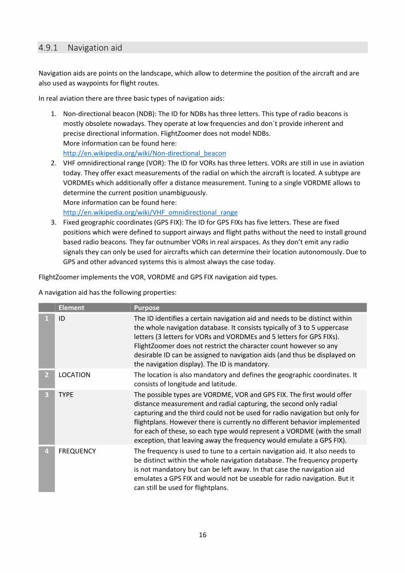
A navigation aid has the following properties:
Element Purpose
1 ID The ID identifies a certain navigation aid and needs to be distinct within the whole navigation database. It consists typically of 3 to 5 uppercase letters (3 letters for VORs and VORDMEs and 5 letters for GPS FIXs). FlightZoomer does not restrict the character count however so any desirable ID can be assigned to navigation aids (and thus be displayed on the navigation display). The ID is mandatory.
2 LOCATION The location is also mandatory and defines the geographic coordinates. It consists of longitude and latitude.
3 TYPE The possible types are VORDME, VOR and GPS FIX. The first would offer distance measurement and radial capturing, the second only radial capturing and the third could not be used for radio navigation but only for flightplans. However there is currently no different behavior implemented for each of these, so each type would represent a VORDME (with the small exception, that leaving away the frequency would emulate a GPS FIX).
4 FREQUENCY The frequency is used to tune to a certain navigation aid. It also needs to be distinct within the whole navigation database. The frequency property is not mandatory but can be left away. In that case the navigation aid emulates a GPS FIX and would not be useable for radio navigation. But it can still be used for flightplans.

17
4.9.2 Airport
Airports can be placed freely on the landscape. They are needed as origin or destination for flightplans and
can also be used to fly ILS approaches.
Airports are a composite data structure because beside the common properties their data model also
contains a list of runways, which are described in the next chapter.
An airport typically also has a radio navigation aid. The data model thus has properties for the airport
navigation aid ID and frequency.
In FlightZoomer the code of airports follows the guidelines from the ICAO (although the airport codes you
define will never be visible outside your mini world!). In real world the ICAO defines the airport codes for
any airport worldwide. ICAO codes have four letters as opposed to the IATA codes having three letters. The
first or the first and the second letter stand for the country and are defined statically (see this map ICAO
countries prefix map).
An airport has the following properties:
Element Purpose
1 CODE The CODE identifies a certain airport according to the ICAO scheme and needs to be distinct within the whole navigation database. It consists of 4 uppercase letters. FlightZoomer does not restrict however the character count so any desirable name can be assigned as CODE to an airport (and thus be displayed on the navigation display). The CODE is mandatory.
2 LOCATION The location is also mandatory and defines the geographic coordinates of the airport navigation aid. It consists of longitude and latitude.
3 ID The ID identifies the radio navigation aid which is located on the airport. The description for ID in chapter 4.9.1 does apply here as well.
4 FREQUENCY This property defines the frequency of the navigation aid which is located on the airport. The description for FREQUENCY in chapter 4.9.1 does apply here as well.
4.9.3 Runway
Runways can also be placed freely on the landscape but they need to be assigned to an airport. They serve
the purpose to fly ILS approaches.

18
An ILS approach is defined by the following parameters (in red):
Additional properties not shown in the diagram is the runway direction.
A runway has the following properties:
Element Purpose
1 LOCATION The location is mandatory and defines the geographic coordinates of the center of the runway. It consists of longitude and latitude.
2 ALTITUDE Altitude of the runway in meter above sea level. It is one possibility to define the actual altitude of the runway. Due to the somewhat limited vertical accuracy of the system, it is recommended however, to define the runway altitude 5…10 m higher. This would give some safety buffer to complete also suboptimal approaches.
3 LENGTH Length of the runway in meter.
4 DIRECTION Direction (primary) between 0° and 360°. The reverse direction does not exist as attribute but is derived from this property.
5 PRIMARY RUNWAY ID The ID of a runway is formed by the first two digits of the direction (e.g. direction = 73° -> ID = 07, direction = 157° -> ID = 16) Parallel runways are suffixed with L, R or C: L for left, R for right and C for center (e.g. 28L and 28R).
6 PRIMARY FREQUENCY The next three properties are optional and describe the ILS approach to the primary runway direction. If the navigation receiver on the groundstation is tuned to this frequency, deviations from the ILS glideslope will be indicated on the primary and navigation displays. Like the frequency of any navigation aid, each ILS frequency needs to be distinct within the whole navigation database.
7 PRIMARY GLIDESLOPE ANGLE The primary glideslope angle is the vertical angle between glideslope and the earth surface. While real ILS typically have 3° glideslope angles, for multicopters 20° is recommended and for
Earth surface Runway
Glideslope Capturing
altitude Glideslope
angle
Recommended
altitude buffer (to be
added to the actual
runway elevation)
MSL
Runway elevation

19
fixed wing planes maybe 5°..10°. This property is only required if a frequency has been specified.
8 PRIMARY INTERCEPTION ALTITUDE
The interception altitude in meter is the altitude, at which the final approach ideally begins. In reality this altitude is 2000´ to 3000´ above the runway. For FlightZoomer the interception altitude typically would be defined 50m to 70m above the runway.
9 REVERSE RUNWAY ID The ID of the reverse runway is formed by the first two digits of the opposite direction (e.g. direction = 73° -> opposite direction = 253° -> ID = 25, direction = 157° -> opposite direction = 337° -> ID = 34). Parallel runways are differentiated as described under PRIMARY RUNWAY ID.
10 REVERSE FREQUENCY The next three properties are also optional and describe the ILS approach to the reverse runway direction. If the navigation receiver on the groundstation is tuned to this frequency, deviations from the ILS glideslope will be indicated on the primary and navigation displays. The frequency of the reverse runway ILS must not only be different than the frequency for the primary direction but also distinct from any other ILS or navigation aid frequency.
11 REVERSE GLIDESLOPE ANGLE The reverse glideslope angle is the vertical angle between the reverse glideslope and the earth surface. For details see PRIMARY GLIDESLOPE ANGLE.
12 REVERSE INTERCEPTION ALTITUDE
The interception altitude in meter is the altitude, at which the final approach ideally begins. For details see PRIMARY INTERCEPTION ALTITUDE.
4.10 System accuracy
As with any technical system, there is a gap between the ideal, perfect accuracy and what can be achieved
with the actual implementation. FlightZoomer is not different in that regard. There are several areas, which
need to be looked at separately in the following chapters.
In general the system accuracy largely depends on whether the flight controller feeds sensor data (via
MAVLink) or whether the phone´s sensor stack is being used (see chapter 4.8).
The information in this chapter mostly is applicable only for phone sourced data.
In each of the following chapters the two possible data sources are marked with the following two
symbols:
Data coming from the phone’s sensors
Data coming from via the MAVLink connection (the source is the flight controller)

20
4.10.1 Time accuracy (lag time)
Description Affected sensors
Due to the system architecture of FlightZoomer the transmission and display of sensor data is not possible in absolute real-time. Obviously mobile network coverage can be impaired temporarily or even be marginal for a longer period of time. As a result there is a lag time until the newest data appears on the groundstation.
Lag time in numbers Affected sensors
Value Unit
Typical lag time 40…120 ms
Sporadic max. lag time
Several seconds -
Contributing factors to the lag time Affected sensors
The currently available
network speed
While a stable 3G connection does easily support the figures above (min 40ms, max 120ms, average 80ms) a 2.5G connection will degrade the average lag time by several 100ms.
Phase while the network type
switches
During the phases while the device is switching between different network types (2.5G, 3G or 4G), the lag time temporarily can worsen. In order to avoid connectivity drops while the device switches between network modes, it is recommended to configure the sensor device to stick to a lower connection speed (than the highest). FlightZoomer does not need 4G, so restricting the network on the sensor device to 3G is sufficient.
Distance between sensor
device and groundstation
A very small impact also comes from the actual distance between the sensor device and the groundstation (via the relay server). Switching from a closely located relay server (e.g. home based) to a cloud based can add some dozens of milliseconds to the total lag time.

21
FlightZoomer design provisions to minimize the effect of lag time
Communication channel
The design of the communication channels from the sensor device to the groundstation is focused especially on recovering from any kind of failure modes. So whenever the connection is lost, connectivity will be reestablished as soon as the network will allow it.
Lag time indication on the ground-
station display
FlightZoomer does also measure and display the current time lag on the groundstation. At any time and on all screens on the top left of the display the time lag bar is indicated:
Lag time test
feature
The FlightZoomer Sensorics app has an in-built feature to measure and display exactly how long it takes for each single transmitted package over the entire communication channel from the sensor device to the groundstation device.
This test is accomplished solely by the Sensorics-app and the relay server and does not need the Groundstation-app. Once the test is started, a second connection from the sensor device to the relay server is established which is used to simulate the complete end-to-end connection.
While the test cannot be performed during the flight (because the Sensorics app needs to be manipulated), the test feature is still very helpful understanding the system time response and the factors that impact it positively and negatively.
The following screenshot shows the lag time test screen. For more details refer to FlightZoomer Sensorics app reference:
Time lag bar This bar grows to the right as long as no updated sensor data is
received. With each set of new received sensor data (location,
altitude, speed, track), the bar is reset. The white bar will reach
100% width after three consecutive seconds without receiving
updated sensor data.

22
Pilot guidelines to mitigate the lag time
The time lag bar needs to be considered while flying.
In case of excessive lag time the displayed information quickly becomes outdated and should not be trusted anymore.
With a multicopter: speed shall be reduced and the LOITER mode should be activated.
If connectivity does not recover before any situational awareness is lost, the flight must continue with visual guidance or the FlightZoomer independent fallback mechanism shall be triggered (e.g. the RETURN-TO-LAUNCH feature of the flight controller).
Especial caution is warranted whenever the current flight trajectory would intersect terrain (e.g. during descends or when flying towards higher terrain).
4.10.2 Position accuracy
Description Affected sensors
The position determination is crucial for the system. It is not only the primary source for navigation but also speed and course are derived from it. Position accuracy is one of the areas, where the flight controller offers greatly improved accuracy over data coming from the phone’s sensors. So the following description more or less applies only for phone sourced position data (see chapter 4.8 for details about how the data source priority can be configured).
Position error in numbers Affected sensors
Value Unit
Typical position error phone
5..15 m
Typical position error flight controller
0.5..2 m
Contributing factors to the position error Affected sensors
GPS inaccuracy The GPS accuracy depends on the momentary conditions (on the number of received satellites). Newer smartphones often also support GLONASS which improves the position accuracy a bit.
Capabilities of the chosen
device
More than one would expect, the actual device has an impact on the position accuracy. During flight testing several devices have been used and the accuracy differences between them has been notable.
Time lag of position feed
Any movement of the aircraft since the last received sensor data obviously adds to the location error.
Constant error of the aerial
images placement
Sometimes the aerial images have a constant error between real and displayed location. This can be corrected using the aerial image offset correction-feature (see also the FlightZoomer Groundstation app reference).

23
FlightZoomer design provisions to minimize the effect of the position error
Position error indication on the ground-
station display
The navigation display on the groundstation shows at any time a yellow circle around the center mark, which indicates the current position error:
Pilot guidelines to mitigate the position error
First and foremost make use of sensor data coming from the flight controller via MAVLink. That way the following points loose mostly their relevance.
The position error circle needs to be considered while flying.
The yellow position error circle should stay away from obstacles.
In case of a sudden loss of position accuracy the flight should be slowed down and continued using fallback navigation mechanisms (visual guidance, RETURN-TO-LAUNCH feature of the flight controller).
Considerable time should be spent flying simple flight profiles and circuits to become familiar with the system response.
This means that at any time fallback possibilities must be available.
Better results and more safety can be achieved with spacious and extensive flight profiles.
FlightZoomer ideally is used to cruise along routes with ample of straight legs and not too many (and too tight) turns.
FlightZoomer does not support 3D flying.
Position error circle This circle indicates at any time the largest possible error
between the displayed and the actual position. The actual
position therefore lays somewhere within the boundaries
of the yellow error circle. On this screenshot a quite
derogated accuracy is shown.
The circle size scales up and down with the display range
(zoom).
Maximum error On this screenshot the largest displayed error is
shown. In case of larger errors the error circle will still
stay within the compass rose.

24
4.10.3 Altitude accuracy
Description Affected sensors
The altitude is derived from the same source like the position (GPS). Therefore the description in the previous chapter is fully applicable for the altitude as well.
Position error in numbers Affected sensors
Value Unit
Typical altitude error phone
5..20 m
Typical altitude error flight controller
1..3 m
FlightZoomer design provisions to minimize the effect of the altitude error
Altitude error indication on the ground-
station display
The current altitude error is shown on the primary display as follows:
Pilot guidelines to mitigate the altitude error
As the terrain usually is much closer vertically than horizontally (except very close to mountains), the altitude tends to be more safety relevant than the position.
To create good altitude awareness therefore additional feedback should be considered (visual tracking, fly with activated ALTITUDE-hold mode, stick to one altitude while cruising…).
Especially double check the plausibility of altitude readouts while descending. Even rather short altitude feed interruptions can develop to dangerous situations. The plane quickly will be actually lower than indicated.
Altitude error bar: The vertical yellow bar indicates
at any time the largest possible
error between the displayed and
the actual altitude.
The actual altitude therefore
with a high probability lays
somewhere within the
boundaries of the error bar.

25
4.10.4 Turn indication accuracy
Description Affected sensors
One of the areas which is affected the most from lag time and the position error is the situational awareness during turns (both about the turn rate and the turn progress). Though using directional data from the flight controller gives much better results, getting turns right is so crucial, that the feature described below is useful in all cases.
FlightZoomer design provisions to optimize the turn accuracy
Flightplan turn countdown
timer
When following flightplan routes, the Flight Director provides a countdown timer both as synthetic voice (“Barking Bob”-feature) and visually on the primary display indicating the beginning of the turn. Once the turn has started there is another timer counting down the remaining turn time (assuming a constant turn rate, see below). The following screenshot shows the Flight Director indicating the current right turn to be continued for exactly another 7.5 seconds:
Once the countdown timers reach zero, the stick shall be released and the aircraft is expected to fly the new course. Additionally the synthetic voice counts down the seconds audibly. This feature requires the standard turn rate to be set for the given aircraft. The standard turn rate can either be set manually in the options…-menu of the Groundstation-app (see the FlightZoomer Groundstation app reference) or also be determined automatically by the turn test feature (see the FlightZoomer Groundstation app reference).
Pilot guidelines to improve the turn accuracy
During free flight apply only rather small turn rates (this behavior is not unrealistic when thinking about real aircraft).
Also don’t fly too long turns. In general apply rather small course corrections (also this is a realistic behavior looking at real aircraft).
Consider a RC transmitter configuration as described in the Installation document. This allows applying constant turn rates which helps getting a feeling about the turn progress even in case of a small time lag on the displays.
Use the mentioned feature above to control turns.

26
4.10.5 Compass accuracy
Description Affected sensors
Compass accuracy is one of the areas that benefits greatly from the much higher accuracy the flight controller usually offers. Therefore the following description more or less only applies for compass data coming from the phone’s internal magnetometer (see chapter 4.8 for details about how the data source priority can be configured). The direction of the compass rose on the primary display always displays either the magnetic direction from the compass sensor (= heading) or - alternatively - the calculated track from the GPS (called Track Lock mode). The accuracy of the later is covered in chapter 4.8. The requirements for a good flight experience with the compass is a small lag time and a smooth step response. While the compass of the smartphone usually responds quicker to directional changes than the GPS Track Lock, the output of the phone’s magnetometer sensor almost always proved to be quite erratic. Therefore avoiding the heading mode completely and choosing the Track Lock mode would be the recommended option when flying without MAVLink. The GPS Track Lock mode has the disadvantage that it does not show the direction if there is no forward speed. Also crab angles can’t be derived from the GPS track only. On the other hand the track above ground is more relevant for navigation.
Contributing factors to the compass error Affected sensors
The actual device
Upper class (and newer) devices like the Lumia 925 have performed better regarding magnetometer accuracy. While still far outclassed by heading data coming from the flight controller it was marginally useable while the older OMNIA 7 had to be flown in GPS Track Lock mode all the time.
The compass calibration
After each power on the compass of the smartphone needs to be calibrated. See Error! Reference source not found..
How the phone is mounted on
the aircraft
Proximity of the magnetometer sensor to other electrical (especially high power) devices.
The compass smoothing
setting
There are four compass smoothing settings available on the groundstation (none, soft, medium or strong).
Pilot guidelines to mitigate the compass error
Enough time should be spent testing various options (with GPS track, witch compass, compass smoothing options) to find out, which combination is the best match for the actual hardware setup and the personal preferences.
If a reliable compass feedback can’t be achieved, revert to the GPS Track Lock mode (which offers nearly the same flying experience).

27
4.10.6 Attitude accuracy
Description Affected sensors
Like the compass the attitude benefits greatly from improved accuracy when coming from the flight controller. Because horizontal accelerations do wrongly impact the gravity determination bank and pitch should only be trusted when the source is the MAVLink. Nevertheless the attitude arguably is of lesser importance when flying with stabilized aircraft like a multicopter, so for all practical purposes the attitude is usually accurate enough.
Contributing factors to the attitude error Affected sensors
Geometry capturing
Conducting the geometry capturing sequence precisely (see also the FlightZoomer Sensorics app reference).
Transmission lag time
The current time lag of the data feed.
28
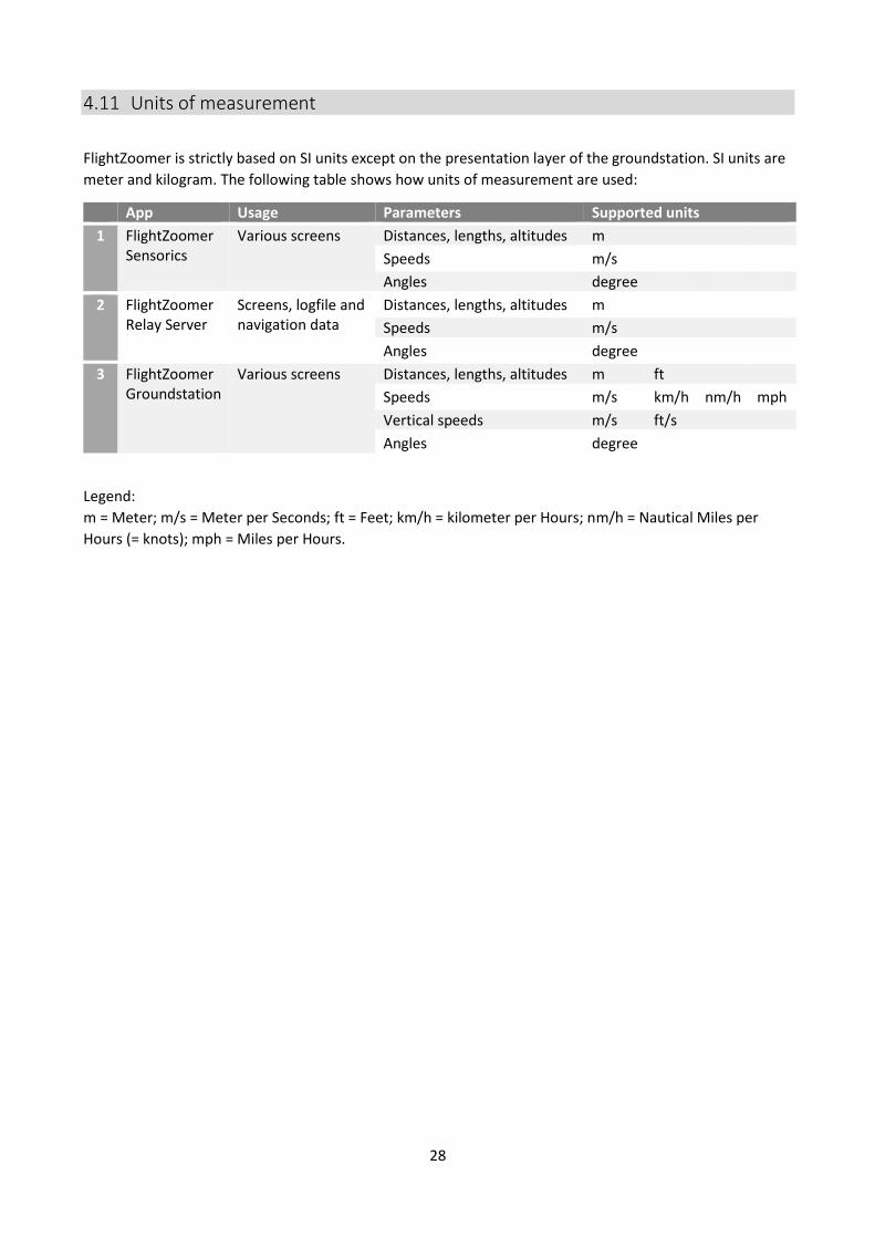
4.11 Units of measurement
FlightZoomer is strictly based on SI units except on the presentation layer of the groundstation. SI units are
meter and kilogram. The following table shows how units of measurement are used:
App Usage Parameters Supported units
1 FlightZoomer Sensorics
Various screens Distances, lengths, altitudes m
Speeds m/s
Angles degree
2 FlightZoomer Relay Server
Screens, logfile and navigation data
Distances, lengths, altitudes m
Speeds m/s
Angles degree
3 FlightZoomer Groundstation
Various screens Distances, lengths, altitudes m ft
Speeds m/s km/h nm/h mph
Vertical speeds m/s ft/s
Angles degree
Legend:
m = Meter; m/s = Meter per Seconds; ft = Feet; km/h = kilometer per Hours; nm/h = Nautical Miles per
Hours (= knots); mph = Miles per Hours.

29
5 Appendix
5.1 Glossary
Abbreviation/term Description Real aviation term
FMS Flight Management System X
ILS Instrument Landing System X
IM Inner Marker X
LNAV Lateral Navigation Auto flight mode where the loaded flightplan is being followed.
X
MM Middle Marker X
ND Navigation Display X
OM Outer Marker X
PFD Primary Flight Display X
VOR VHF omnidirectional range X


