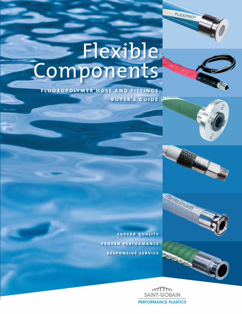
f lu o r o p o lym e r h o s e a n d f it t i n g s b uy e r ’s g u i d e
FlexibleComponents
s u p e r b q u a l i t y
p r o v e n p e r f o r m a n c e
r e s p o n s i v e s e r v i c e
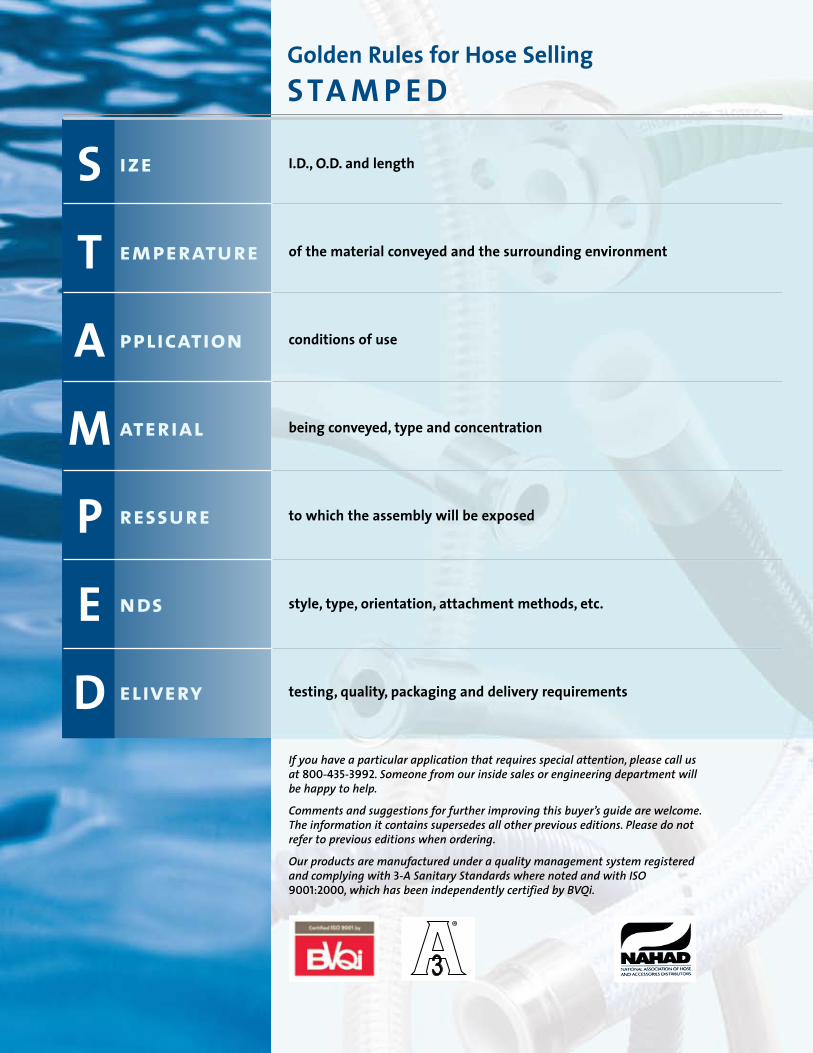
I.D., O.D. and length
of the material conveyed and the surrounding environment
conditions of use
being conveyed, type and concentration
to which the assembly will be exposed
style, type, orientation, attachment methods, etc.
testing, quality, packaging and delivery requirements
S
T
A
M
P
E
D
ize
emperature
pplication
aterial
ressure
nds
elivery
If you have a particular application that requires special attention, please call us at 800-435-3992. Someone from our inside sales or engineering department will be happy to help.
Comments and suggestions for further improving this buyer’s guide are welcome. The information it contains supersedes all other previous editions. Please do not refer to previous editions when ordering.
Our products are manufactured under a quality management system registered and complying with 3-A Sanitary Standards where noted and with ISO 9001:2000, which has been independently certified by BVQi.
Golden Rules for Hose SellingS TA M P E D
1
These characteristics should be a given with any manufacturer of hose assemblies. Flexible Components of Saint-Gobain Performance Plastics meets — indeed, greatly exceeds — these fundamental standards.
As this catalog makes clear, innovative engineering and close attention to the issues facing those who use our products set Flexible Components hose assemblies apart from all others on the market.
Our Chemfluor® fluoropolymer extruded tubing — the foundation of all our hose products — sets the industry standard for chemical and corrosion resistance, ease of use, and compliance with all key industry standards.
Our S.I.B.® (Smooth Inner Bore) technology provides a totally seamless transition between hose and fitting, virtually eliminating the problems caused by particle entrapment in standard barb assemblies and simplifying maintenance.
Our unique Flare-Thru fitting design ensures that the material being conveyed contacts only pure, non-contaminating Chemfluor® fluoropolymer tubing from end to end.
Everything we do at Flexible Components is based on one simple premise: We want our hose and fitting products to be best in class. We believe the many customers who swear by our products are the most compelling proof of the success of this single-minded focus.
Chemfluor® — the Flexible Components AdvantageSaint-Gobain’s Chemfluor® fluoropolymer resins offer a number of key performance advantages that extend across the entire line of Flexible Components hose products.
Superior Chemical Resistance • Chemically inert to all materials
Unsurpassed Corrosion Resistance
Mechanically Tough, Yet Flexible
Approvals • Complies with major sanitary standards - FDA (21CFR177.1550), USDA and U.S. Pharmacopeia
Class VI (certain materials vary in terms of meeting one or both standards)
- Imparts no taste or odor to media being conveyed
Wide Range of Operating Temperatures • Hose available rated from -100ºF (-73ºC) to +500ºF (+260ºC)• Proven durability in hot and cold steam cycling applications (e.g., plywood manufacture, laundry press)
High Pressure Ratings/Superior Resistance to Volumetric Expansion• Facilitates use in quick-response hydraulic and pneumatic systems
Zero Maintenance• Non-stick inner surface prevents material build-up
Good Erosion Resistance• No significant loss of wall thickness, even after many years of service in corrosive environments
Low Thermal Conductivity• Hose construction helps insulate conveyed materials from outside environment• May reduce process costs
IMPORTANT NOTE: Data given is for hose only. Fitting vs. hose pressure limitations must be considered and the lower of the two ratings must be used on assemblies.
A Word about This Buyer’s GuideThis comprehensive buyer’s guide provides an in-depth view of the full range of products available from the Flexible Components brand of Saint-Gobain Performance Plastics. The guide is divided into three main color-coded sections: Hose (blue), Fittings and Adapters (green) and Engineering Guide (teal).
You will find application information, complete hose specification data, basic dimensional drawings of the many types of fittings we offer, installation instructions and much more. We envision this buyer’s guide as the ultimate reference source for those who are responsible for determining exactly what combination of hose and fitting is required to meet their individual application requirements.
Dimensional data is for reference only! For manufacturing tolerances, please consult factory.
Saint-Gobain Performance PlasticsFlexible Components
• Superb quality
• Proven performance
• Responsive service
! Important:
2
Smooth Tube Hose
PharmaSmoothTM................................... 6
FlexPro® Series . . . . . . . . . . . . . . . . . . . . . . . . . . . . . . . . . . . . .7
TLCTCOSeries Hose Assemblies. . . . . . . . . . . . . . . . . . . . . 8
CTLCTSeries . . . . . . . . . . . . . . . . . . . . . . . . . . . . . . . . . . . . . . . . 9
TLCT/WTLCT/SFTLSeries . . . . . . . . . . . . . . . . . . . . . . . . . . . . 10
WTLCTPFASeries. . . . . . . . . . . . . . . . . . . . . . . . . . . . . . . . . . . .11
W.S.I.B.Series Hose Assemblies. . . . . . . . . . . . . . . . . . . . . 12
TS/TBSeries. . . . . . . . . . . . . . . . . . . . . . . . . . . . . . . . . . . . . . . 13
TSSSeries . . . . . . . . . . . . . . . . . . . . . . . . . . . . . . . . . . . . . . . . . 14
THSeries. . . . . . . . . . . . . . . . . . . . . . . . . . . . . . . . . . . . . . . . . . 15
MTLSeries Hose Assemblies . . . . . . . . . . . . . . . . . . . . 16–17
MTLSJSeries Hose Assemblies. . . . . . . . . . . . . . . . . . . 18–19
Convoluted Hose
TWOB/TBOB/TWOBHV/TBOBHVSeries . . . . . . . . . . . . .20
TWOY/TBOYSeries . . . . . . . . . . . . . . . . . . . . . . . . . . . . . . . . . 21
TWOK/TBOKSeries . . . . . . . . . . . . . . . . . . . . . . . . . . . . . . . . 22
TWOP/TBOPSeries . . . . . . . . . . . . . . . . . . . . . . . . . . . . . . . . . 23
WCS/BCSSeries. . . . . . . . . . . . . . . . . . . . . . . . . . . . . . . . . . . . 24
WCSSSeries. . . . . . . . . . . . . . . . . . . . . . . . . . . . . . . . . . . . . . . 25
WCP/BCPSeries. . . . . . . . . . . . . . . . . . . . . . . . . . . . . . . . . . . .26
Stainless Steel Metal Hose . . . . . . . . . . . . . . . . . . . . . 27–28
Sight Flow Indicators. . . . . . . . . . . . . . . . . . . . . . . . . . . 29–30
CL Series Chlorine Transfer Hose Assemblies. . . . . . . . . 31
EHH Series Electrically Heated Hose . . . . . . . . . . . . . . . . 32
Overview . . . . . . . . . . . . . . . . . . . . . . . . . . . . . . . . . . . . . . . . . . . . . 1
Product Selection Guide. . . . . . . . . . . . . . . . . . . . . . . . . . . . .4–5
tabl
e of
con
tent
s
Table of Contents
hose
introduction
Introduction . . . . . . . . . . . . . . . . . . . . . . . . . . . . . . . . . . . . . 33–34
Swiv-L-Flex® . . . . . . . . . . . . . . . . . . . . . . . . . . . . . . . . . . . . . . . . . 35
Flare-Thru . . . . . . . . . . . . . . . . . . . . . . . . . . . . . . . . . . . . . . . . . . .36
Style10FT•Sanitary Clamp Style . . . . . . . . . . . . . . . . . . 37
Style12FT•150#Flanged. . . . . . . . . . . . . . . . . . . . . . . . . . .38
Style16FT•Female Cam and Groove . . . . . . . . . . . . . . . .39
Style50FT/51FT•Male/Female “I” Line Sanitary. . . . . .40
PermaSeal® . . . . . . . . . . . . . . . . . . . . . . . . . . . . . . . . . . . . . . . . . 41
NPT . . . . . . . . . . . . . . . . . . . . . . . . . . . . . . . . . . . . . . . . . . . . . . .42
Style02•J.I.C. Female Swivel . . . . . . . . . . . . . . . . . . . . . . 43
Style03•Male NPT . . . . . . . . . . . . . . . . . . . . . . . . . . . . . . . .44
Style05/06•Female NPT . . . . . . . . . . . . . . . . . . . . . . . . . . 45
Style08•J.I.C.Adapter Union Male . . . . . . . . . . . . . . . .46
Flange. . . . . . . . . . . . . . . . . . . . . . . . . . . . . . . . . . . . . . . . . . . . . 47
Style12•316L Stainless Steel Flange Retainer . . . . . . 48
Style12T•PFA EncapsulatedFlange Retainer . . . . . . . .49
Sanitary . . . . . . . . . . . . . . . . . . . . . . . . . . . . . . . . . . . . . . . . . . .50
Style10/10U•Sanitary Clamp/Step Up . . . . . . . . . . . . . 51
Style10L/11L•90°Elbow Full Size/Mini. . . . . . . . . . . . . . 52
Style11•Mini Sanitary Clamp . . . . . . . . . . . . . . . . . . . . . . 53
Style20•Bevel Seat . . . . . . . . . . . . . . . . . . . . . . . . . . . . . . . 54
Style40•Male with Threads. . . . . . . . . . . . . . . . . . . . . . . 55
Style41•Butt Weld/Tube Size . . . . . . . . . . . . . . . . . . . . . . 56
Style50/51•Male/Female “I” Line . . . . . . . . . . . . . . . . . . 57
fittings
NEW!
NEW!
NEW!
3
table of contents
Pipe Interface Adapters . . . . . . . . . . . . . . . . . . . . . . . . . . . . . . 71
10x12Sanitary x150#Flanged . . . . . . . . . . . . . . . . . . . . 72
12x16150#Flanged xFemale Cam and Groove . . . . . 73
12x50150#Flanged x Male “I” Line. . . . . . . . . . . . . . . . 74
12x51150#Flanged x Female “I” Line . . . . . . . . . . . . . . . 75
Style 18T•PFA Encapsulated Male Cam and Groove x 150# Flanged . . . . . . . . . . . . . . . . . . . . . . . . . . . . . . . . . . . 76
Style 19T•PFAEncapsulated Male Spool . . . . . . . . . . . . 77
PureFit® 316 Stainless Steel. . . . . . . . . . . . . . . . . . . . . . . . . 78
Cam and Groove . . . . . . . . . . . . . . . . . . . . . . . . . . . . . . . . . . . 58
Style16•Female 316 Stainless Steel Swivel. . . . . . . . . . 59
Style16T•Female PFA Encapsulated Swivel . . . . . . . . .60
Style17•Male 316 Stainless Steel . . . . . . . . . . . . . . . . . . . 61
Style17T•Male PFA Encapsulated . . . . . . . . . . . . . . . . . .62
Instrumentation . . . . . . . . . . . . . . . . . . . . . . . . . . . . . . . . . . .63
Style31•Tube Connector . . . . . . . . . . . . . . . . . . . . . . . . . 64
Style31FN•Tube Connector with Ferrules and Nut . .65
Style32•Tube Adapter . . . . . . . . . . . . . . . . . . . . . . . . . . . .66
Style33•O-Ring . . . . . . . . . . . . . . . . . . . . . . . . . . . . . . . . . . . 67
Style34•Vacuum Female . . . . . . . . . . . . . . . . . . . . . . . . . 68
Style35•Vacuum Male . . . . . . . . . . . . . . . . . . . . . . . . . . . .69
Style01•Butt Weld/Pipe Size. . . . . . . . . . . . . . . . . . . . . 70
Additional Product Services . . . . . . . . . . . . . . . . . . . . . 79–80
Steam Table . . . . . . . . . . . . . . . . . . . . . . . . . . . . . . . . . . . . . . . . . 81
Testing and Measurement. . . . . . . . . . . . . . . . . . . . . . . . . . . 82
Live Hose Length for Offset Motion . . . . . . . . . . . . . . . . . . .83
Material Specification References . . . . . . . . . . . . . . . . . . . . .84
Application References . . . . . . . . . . . . . . . . . . . . . . . . . . . . . . 85
Technical Terms Used . . . . . . . . . . . . . . . . . . . . . . . . . . . . . . . .86
General Hose Installation Precautions . . . . . . . . . . . . 87–88
Installation . . . . . . . . . . . . . . . . . . . . . . . . . . . . . . . . . . . . . 88-89
Temperature Conversion Chart . . . . . . . . . . . . . . . . . . . . . . .90
Chemfluor® Fluoropolymer References. . . . . . . . . . . . . . . . 91
Industry Approval and Compliance References. . . . . . . . . 91
Chemical Resistance Ratings . . . . . . . . . . . . . . . . . . . . . 92–94
How to Order Hose Assemblies . . . . . . . . . . . . . . . . . 95–100
engineering guide
4
product description
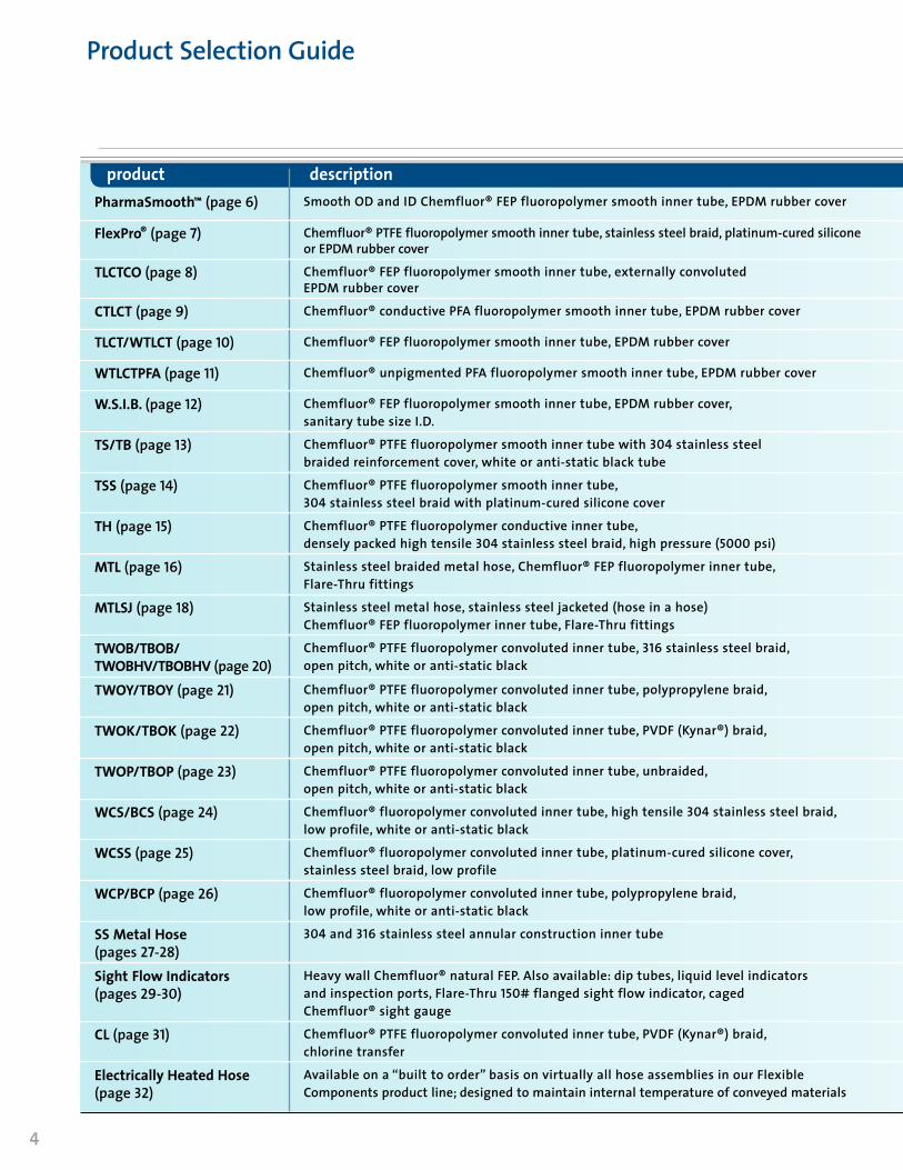
Product Selection Guide
PharmaSmooth™ (page 6) Smooth OD and ID Chemfluor® FEP fluoropolymer smooth inner tube, EPDM rubber cover • • • • • •FlexPro® (page 7) Chemfluor® PTFE fluoropolymer smooth inner tube, stainless steel braid, platinum-cured silicone
or EPDM rubber cover• • • • • •
TLCTCO (page 8) Chemfluor® FEP fluoropolymer smooth inner tube, externally convoluted EPDM rubber cover
• • • • •CTLCT (page 9) Chemfluor® conductive PFA fluoropolymer smooth inner tube, EPDM rubber cover • • •TLCT/WTLCT (page 10) Chemfluor® FEP fluoropolymer smooth inner tube, EPDM rubber cover • • • • • •WTLCTPFA (page 11) Chemfluor® unpigmented PFA fluoropolymer smooth inner tube, EPDM rubber cover • •W.S.I.B. (page 12) Chemfluor® FEP fluoropolymer smooth inner tube, EPDM rubber cover,
sanitary tube size I.D.• • •
TS/TB (page 13) Chemfluor® PTFE fluoropolymer smooth inner tube with 304 stainless steel braided reinforcement cover, white or anti-static black tube
• • • • •TSS (page 14) Chemfluor® PTFE fluoropolymer smooth inner tube,
304 stainless steel braid with platinum-cured silicone cover• • • •
TH (page 15) Chemfluor® PTFE fluoropolymer conductive inner tube, densely packed high tensile 304 stainless steel braid, high pressure (5000 psi)
• •MTL (page 16) Stainless steel braided metal hose, Chemfluor® FEP fluoropolymer inner tube,
Flare-Thru fittings• • •
MTLSJ (page 18) Stainless steel metal hose, stainless steel jacketed (hose in a hose)Chemfluor® FEP fluoropolymer inner tube, Flare-Thru fittings
• •TWOB/TBOB/TWOBHV/TBOBHV (page 20)
Chemfluor® PTFE fluoropolymer convoluted inner tube, 316 stainless steel braid, open pitch, white or anti-static black
• • •TWOY/TBOY (page 21) Chemfluor® PTFE fluoropolymer convoluted inner tube, polypropylene braid,
open pitch, white or anti-static black• • •
TWOK/TBOK (page 22) Chemfluor® PTFE fluoropolymer convoluted inner tube, PVDF (Kynar®) braid, open pitch, white or anti-static black
• • •TWOP/TBOP (page 23) Chemfluor® PTFE fluoropolymer convoluted inner tube, unbraided,
open pitch, white or anti-static black• • • •
WCS/BCS (page 24) Chemfluor® fluoropolymer convoluted inner tube, high tensile 304 stainless steel braid, low profile, white or anti-static black
• • • • •WCSS (page 25) Chemfluor® fluoropolymer convoluted inner tube, platinum-cured silicone cover,
stainless steel braid, low profile• • • •
WCP/BCP (page 26) Chemfluor® fluoropolymer convoluted inner tube, polypropylene braid, low profile, white or anti-static black
• • •SS Metal Hose (pages 27-28)
304 and 316 stainless steel annular construction inner tube • •Sight Flow Indicators(pages 29-30)
Heavy wall Chemfluor® natural FEP. Also available: dip tubes, liquid level indicators and inspection ports, Flare-Thru 150# flanged sight flow indicator, caged Chemfluor® sight gauge
• • • • •
CL (page 31) Chemfluor® PTFE fluoropolymer convoluted inner tube, PVDF (Kynar®) braid,chlorine transfer
•Electrically Heated Hose(page 32)
Available on a “built to order” basis on virtually all hose assemblies in our Flexible Components product line; designed to maintain internal temperature of conveyed materials
• • • •

5
Pharmaceutical & Biotech
Chemical
Laboratory
Food & Beverage
Semi Conductor
Industrial
PharmaSmooth™ (page 6) Smooth OD and ID Chemfluor® FEP fluoropolymer smooth inner tube, EPDM rubber cover • • • • • •FlexPro® (page 7) Chemfluor® PTFE fluoropolymer smooth inner tube, stainless steel braid, platinum-cured silicone
or EPDM rubber cover• • • • • •
TLCTCO (page 8) Chemfluor® FEP fluoropolymer smooth inner tube, externally convoluted EPDM rubber cover
• • • • •CTLCT (page 9) Chemfluor® conductive PFA fluoropolymer smooth inner tube, EPDM rubber cover • • •TLCT/WTLCT (page 10) Chemfluor® FEP fluoropolymer smooth inner tube, EPDM rubber cover • • • • • •WTLCTPFA (page 11) Chemfluor® unpigmented PFA fluoropolymer smooth inner tube, EPDM rubber cover • •W.S.I.B. (page 12) Chemfluor® FEP fluoropolymer smooth inner tube, EPDM rubber cover,
sanitary tube size I.D.• • •
TS/TB (page 13) Chemfluor® PTFE fluoropolymer smooth inner tube with 304 stainless steel braided reinforcement cover, white or anti-static black tube
• • • • •TSS (page 14) Chemfluor® PTFE fluoropolymer smooth inner tube,
304 stainless steel braid with platinum-cured silicone cover• • • •
TH (page 15) Chemfluor® PTFE fluoropolymer conductive inner tube, densely packed high tensile 304 stainless steel braid, high pressure (5000 psi)
• •MTL (page 16) Stainless steel braided metal hose, Chemfluor® FEP fluoropolymer inner tube,
Flare-Thru fittings• • •
MTLSJ (page 18) Stainless steel metal hose, stainless steel jacketed (hose in a hose)Chemfluor® FEP fluoropolymer inner tube, Flare-Thru fittings
• •TWOB/TBOB/TWOBHV/TBOBHV (page 20)
Chemfluor® PTFE fluoropolymer convoluted inner tube, 316 stainless steel braid, open pitch, white or anti-static black
• • •TWOY/TBOY (page 21) Chemfluor® PTFE fluoropolymer convoluted inner tube, polypropylene braid,
open pitch, white or anti-static black• • •
TWOK/TBOK (page 22) Chemfluor® PTFE fluoropolymer convoluted inner tube, PVDF (Kynar®) braid, open pitch, white or anti-static black
• • •TWOP/TBOP (page 23) Chemfluor® PTFE fluoropolymer convoluted inner tube, unbraided,
open pitch, white or anti-static black• • • •
WCS/BCS (page 24) Chemfluor® fluoropolymer convoluted inner tube, high tensile 304 stainless steel braid, low profile, white or anti-static black
• • • • •WCSS (page 25) Chemfluor® fluoropolymer convoluted inner tube, platinum-cured silicone cover,
stainless steel braid, low profile• • • •
WCP/BCP (page 26) Chemfluor® fluoropolymer convoluted inner tube, polypropylene braid, low profile, white or anti-static black
• • •SS Metal Hose (pages 27-28)
304 and 316 stainless steel annular construction inner tube • •Sight Flow Indicators(pages 29-30)
Heavy wall Chemfluor® natural FEP. Also available: dip tubes, liquid level indicators and inspection ports, Flare-Thru 150# flanged sight flow indicator, caged Chemfluor® sight gauge
• • • • •
CL (page 31) Chemfluor® PTFE fluoropolymer convoluted inner tube, PVDF (Kynar®) braid,chlorine transfer
•Electrically Heated Hose(page 32)
Available on a “built to order” basis on virtually all hose assemblies in our Flexible Components product line; designed to maintain internal temperature of conveyed materials
• • • •
product selection guide
6
features & benefits details
applications
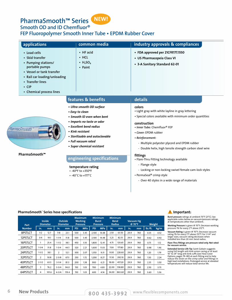
• Load cells• Skid transfer• Pumping stations/ portable pumps• Vessel or tank transfer• Rail car loading/unloading• Transfer lines• CIP• Chemical process lines
temperature rating • -40ºF to +350ºF• -40˚C to +177˚C
engineering specifications
Burst pressure ratings at ambient 70°F (21°C). See applicable notes below on vacuum/pressure ratings at temperatures other than ambient.Working Pressure is given @ 70°F; Decrease working pressure 1% for every 2°F above 212°F.Vacuum Rating is given @ 70°F; Decrease vacuum rating 1% for every 2°F above 212°F. For 1-1/4" and larger sizes, vacuum rating decreases when installed less than 2X min. bend radius.Flare-Thru fittings are pressure rated only. Not rated for vacuum service.Extended Service Life Tip: Saint-Gobain suggests using full-length anti-kink armor casing or at least 16" to 24" long anti-kink cuffs (see Hose Cover Options, pages 79–80) at each fitting end to help reduce the strain on the crimp collar and fittings in high load installations. Prolonged service at elevated temperatures will reduce total service life.
PharmaSmooth™
PharmaSmoothTM Series hose specifications
•UltrasmoothODsurface•Easytoclean•SmoothIDevenwhenbent•Impartsnotasteorodor•Excellentbendradius•Kinkresistant•Sterilizableandautoclavable•Fullvacuumrated•Superchemicalresistant
colors • Light gray with white layline in gray lettering
• Special colors available with minimum order quantities
construction • Inner Tube: Chemfluor® FEP
• Cover: EPDM rubber
• Reinforcement:
- Multiple polyester plycord and EPDM rubber
- Double helix, high tensile strength carbon steel wire
fittings • Flare-Thru Fitting technology available
- Flange style
- Locking or non-locking swivel female cam-lock styles
• PermaSeal® crimp style
- Over 40 styles in a wide range of materials
PharmaSmooth™ SeriesSmooth OD and ID Chemfluor®FEP Fluoropolymer Smooth Inner Tube • EPDM Rubber Cover
8PSTLCT12PSTLCT16PSTLCT20PSTLCT24PSTLCT32PSTLCT40PSTLCT48PSTLCT64PSTLCT
NEW!
8 0 0 4 3 5 - 3 9 9 2 www.flexiblecomponents.comNew Products
! Important:
New Products
common media industry approvals & compliances
• FDA approved per 21CFR177.1550• US Pharmacopeia Class VI
• 3-A Sanitary Standard 62-01
• HF acid• HCL • H2SO4
• Paint
Maximum Minimum Minimum Inside Outside Working Burst Bend Vacuum Hg Part Diameter Diameter Pressure Pressure Radius @ 70°F Weight Number in. mm in. mm PSI MPa PSI MPa in. mm in. mm lb./ft. kg/m
1/2
3/4
1
1-1/4
1-1/2
2
2-1/2
3
4
12.7
19.1
25.4
31.8
38.1
50.8
63.5
76.2
101.6
7/8
1-1/4
1-1/2
1-3/4
2
2-5/8
3-1/4
3-3/4
4-3/4
23.1
31.8
38.1
44.5
52.1
67.3
81.3
94.0
119.4
500
500
450
320
300
250
200
150
150
3.45
3.45
3.10
2.21
2.07
1.72
1.38
1.03
1.03
2,100
2,100
1,800
1,600
1,350
1,200
900
700
600
14.48
14.48
12.41
11.03
9.31
8.27
6.21
4.83
4.14
2.50
3.25
4.75
7.00
9.00
11.50
18.00
22.00
34.00
63.50
82.55
120.65
177.80
228.60
292.10
457.20
558.80
863.60
29.9
29.9
29.9
29.9
29.9
29.9
29.9
29.9
29.9
760
760
760
760
760
760
760
760
760
0.35
0.62
0.75
0.98
1.20
1.50
2.35
2.50
3.60
0.52
0.92
1.12
1.46
1.79
2.24
3.50
3.73
5.36
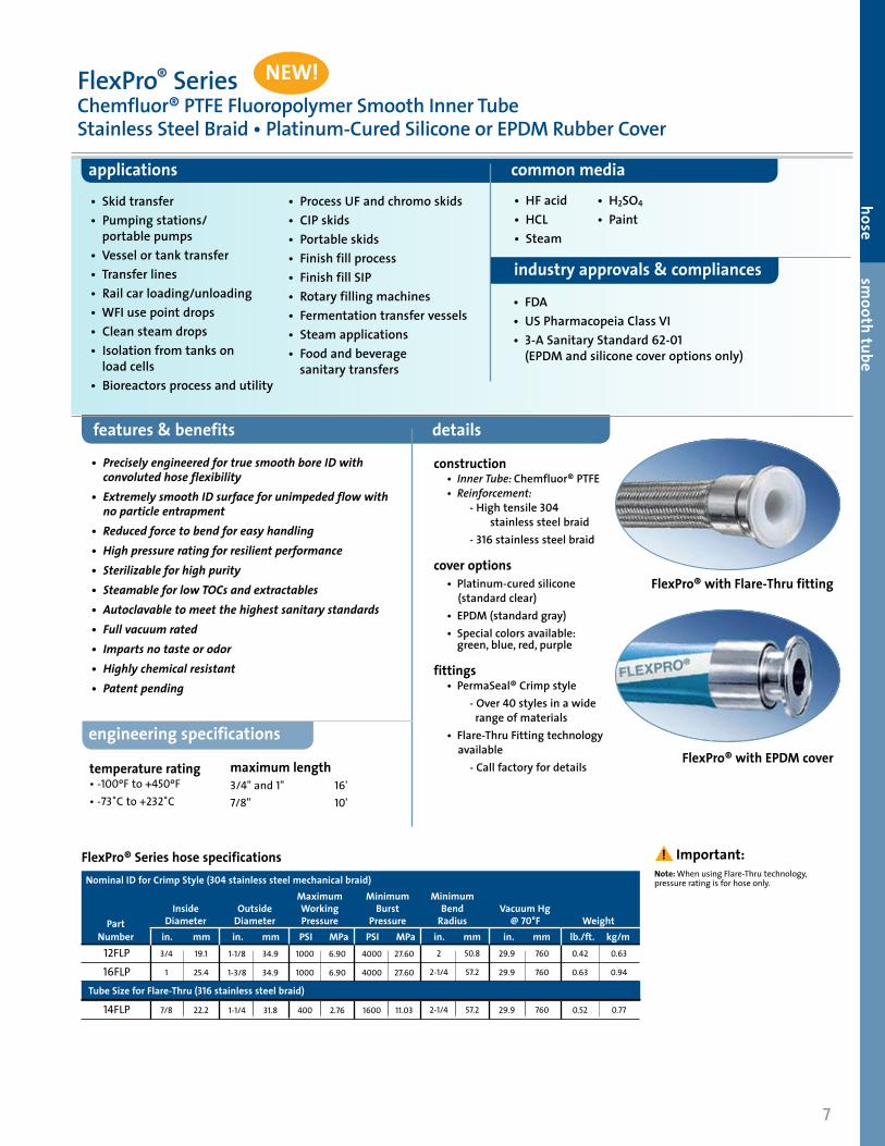
FlexPro® SeriesChemfluor® PTFE Fluoropolymer Smooth Inner TubeStainless Steel Braid • Platinum-Cured Silicone or EPDM Rubber Cover
features & benefits details
applications common media
• PreciselyengineeredfortruesmoothboreIDwith convolutedhoseflexibility• ExtremelysmoothIDsurfaceforunimpededflowwith noparticleentrapment• Reducedforcetobendforeasyhandling• Highpressureratingforresilientperformance• Sterilizableforhighpurity• SteamableforlowTOCsandextractables• Autoclavabletomeetthehighestsanitarystandards• Fullvacuumrated• Impartsnotasteorodor• Highlychemicalresistant• Patentpending
construction • Inner Tube: Chemfluor® PTFE • Reinforcement: - High tensile 304
stainless steel braid - 316 stainless steel braid
cover options • Platinum-cured silicone
(standard clear) • EPDM (standard gray) • Special colors available:
green, blue, red, purple
fittings • PermaSeal® Crimp style
- Over 40 styles in a wide range of materials
• Flare-Thru Fitting technology available
- Call factory for details
• Skid transfer• Pumping stations/ portable pumps• Vessel or tank transfer• Transfer lines• Rail car loading/unloading• WFI use point drops• Clean steam drops• Isolation from tanks on load cells• Bioreactors process and utility
• Process UF and chromo skids• CIP skids• Portable skids• Finish fill process• Finish fill SIP• Rotary filling machines• Fermentation transfer vessels• Steam applications• Food and beverage sanitary transfers
FlexPro® with Flare-Thru fitting
FlexPro® with EPDM cover
hose smooth tube
engineering specifications
NEW!
7
industry approvals & compliances
• FDA• US Pharmacopeia Class VI• 3-A Sanitary Standard 62-01 (EPDM and silicone cover options only)
temperature rating • -100ºF to +450ºF• -73˚C to +232˚C
Maximum Minimum Minimum Inside Outside Working Burst Bend Vacuum Hg Part Diameter Diameter Pressure Pressure Radius @ 70°F Weight Number in. mm in. mm PSI MPa PSI MPa in. mm in. mm lb./ft. kg/m
FlexPro® Series hose specifications
12FLP16FLP
14FLP
3/4
1
7/8
19.1
25.4
22.2
1-1/8
1-3/8
1-1/4
34.9
34.9
31.8
1000
1000
400
6.90
6.90
2.76
4000
4000
1600
27.60
27.60
11.03
2
2-1/4
2-1/4
50.8
57.2
57.2
29.9
29.9
29.9
0.42
0.63
0.52
760
760
760
0.63
0.94
0.77
Nominal ID for Crimp Style (304 stainless steel mechanical braid)
Tube Size for Flare-Thru (316 stainless steel braid)
maximum length 3/4"and 1" 16'7/8" 10'
• HF acid• HCL • Steam
• H2SO4
• Paint
Note: When using Flare-Thru technology, pressure rating is for hose only.
! Important:
8
features & benefits details
applications
• Load cells• Skid transfer• Pumping stations/ portable pumps• Vessel or tank transfer• Rail car loading/unloading• Transfer lines• Chemical process lines
temperature rating • -40ºF to +350ºF• -40˚C to +177˚C
engineering specifications
Burst pressure ratings at ambient 70°F (21°C). See applicable notes below on vacuum/pressure ratings at temperatures other than ambient.Working Pressure is given @ 70°F; Decrease working pressure 1% for every 2°F above 212°F.Vacuum Rating is given @ 70°F; Decrease vacuum rating 1% for every 2°F above 212°F. For 1-1/2" and larger sizes, vacuum rating decreases when installed less than 2X min. bend radius.Extended Service Life Tip: Saint-Gobain suggests using full-length anti-kink armor casing or at least 16" to 24" long anti-kink cuffs (see Hose Cover Options, pages 79–80) at each fitting end to help reduce the strain on the crimp collar and fittings in high load installations. Prolonged service at elevated temperatures will reduce total service life.
Maximum Minimum Minimum Inside Outside Working Burst Bend Vacuum Hg Part Diameter Diameter Pressure Pressure Radius @ 70°F Weight Number in. mm in. mm PSI MPa PSI MPa in. mm in. mm lb./ft. kg/m
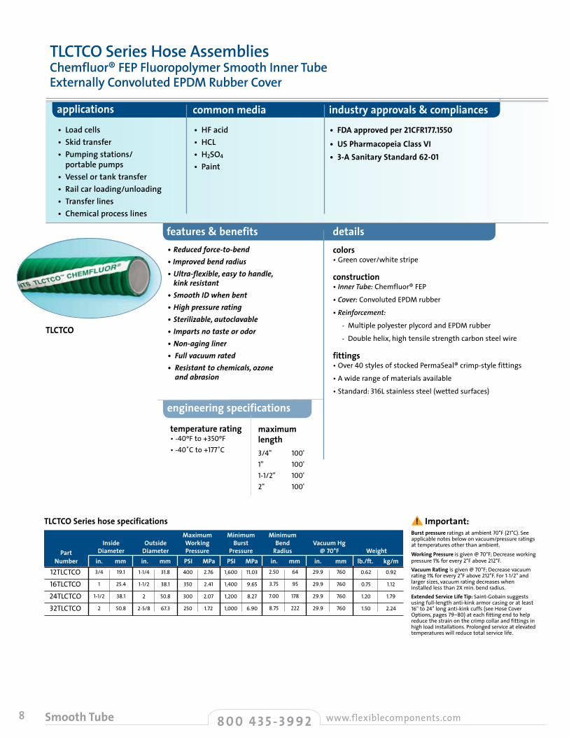
TLCTCO
TLCTCO Series hose specifications
•Reducedforce-to-bend•Improvedbendradius• Ultra-flexible,easytohandle,kinkresistant
•SmoothIDwhenbent•Highpressurerating•Sterilizable,autoclavable•Impartsnotasteorodor•Non-agingliner•Fullvacuumrated•Resistanttochemicals,ozoneandabrasion
colors • Green cover/white stripe
construction • Inner Tube: Chemfluor® FEP
• Cover: Convoluted EPDM rubber
• Reinforcement:
- Multiple polyester plycord and EPDM rubber
- Double helix, high tensile strength carbon steel wire
fittings • Over 40 styles of stocked PermaSeal® crimp-style fittings
• A wide range of materials available
• Standard: 316L stainless steel (wetted surfaces)
TLCTCO Series Hose AssembliesChemfluor® FEP Fluoropolymer Smooth Inner TubeExternally Convoluted EPDM Rubber Cover
12TLCTCO16TLCTCO24TLCTCO32TLCTCO
3/4
1
1-1/2
2
19.1
25.4
38.1
50.8
1-1/4
1-1/2
2
2-5/8
31.8
38.1
50.8
67.3
400
350
300
250
2.76
2.41
2.07
1.72
1,600
1,400
1,200
1,000
11.03
9.65
8.27
6.90
2.50
3.75
7.00
8.75
64
95
178
222
29.9
29.9
29.9
29.9
760
760
760
760
0.62
0.75
1.20
1.50
0.92
1.12
1.79
2.24
8 0 0 4 3 5 - 3 9 9 2 www.flexiblecomponents.comNew Products
! Important:
Smooth Tube
maximumlength3/4" 100'1" 100'1-1/2" 100'2" 100'
common media industry approvals & compliances
• FDA approved per 21CFR177.1550• US Pharmacopeia Class VI• 3-A Sanitary Standard 62-01
• HF acid• HCL • H2SO4
• Paint
features & benefits details
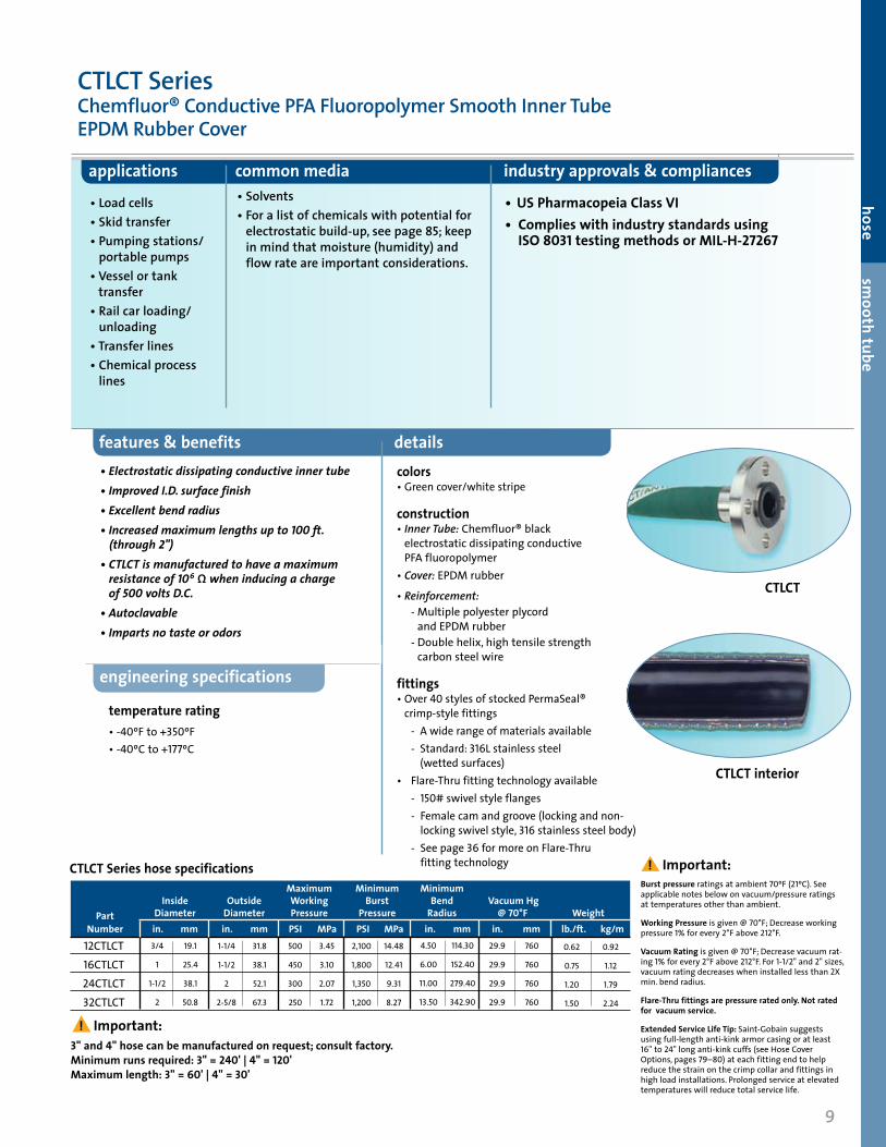
applications common media industry approvals & compliances
• Load cells• Skid transfer• Pumping stations/
portable pumps• Vessel or tank
transfer• Rail car loading/
unloading• Transfer lines• Chemical process
lines
• US Pharmacopeia Class VI• Complies with industry standards using
ISO 8031 testing methods or MIL-H-27267
colors • Green cover/white stripe
construction • Inner Tube: Chemfluor® black
electrostatic dissipating conductive PFA fluoropolymer
• Cover: EPDM rubber
• Reinforcement: - Multiple polyester plycord
and EPDM rubber - Double helix, high tensile strength
carbon steel wire
fittings • Over 40 styles of stocked PermaSeal®
crimp-style fittings - A wide range of materials available - Standard: 316L stainless steel
(wetted surfaces)• Flare-Thru fitting technology available - 150# swivel style flanges - Female cam and groove (locking and non-
locking swivel style, 316 stainless steel body) - See page36 for more on Flare-Thru
fitting technology
temperature rating• -40ºF to +350ºF • -40ºC to +177ºC
engineering specifications
CTLCT Series hose specifications
CTLCT SeriesChemfluor® Conductive PFA Fluoropolymer Smooth Inner Tube EPDM Rubber Cover
Maximum Minimum Minimum Inside Outside Working Burst Bend Vacuum Hg Part Diameter Diameter Pressure Pressure Radius @ 70°F Weight Number in. mm in. mm PSI MPa PSI MPa in. mm in. mm lb./ft. kg/m
3" and 4" hose can be manufactured on request; consult factory. Minimum runs required: 3" = 240' | 4" = 120' Maximum length: 3" = 60' | 4" = 30'
12CTLCT16CTLCT24CTLCT32CTLCT
3/4
1
1-1/2
2
19.1
25.4
38.1
50.8
1-1/4
1-1/2
2
2-5/8
31.8
38.1
52.1
67.3
500
450
300
250
3.45
3.10
2.07
1.72
2,100
1,800
1,350
1,200
14.48
12.41
9.31
8.27
4.50
6.00
11.00
13.50
114.30
152.40
279.40
342.90
29.9
29.9
29.9
29.9
760
760
760
760
• Solvents• For a list of chemicals with potential for
electrostatic build-up, see page 85; keep in mind that moisture (humidity) and flow rate are important considerations.
•Electrostaticdissipatingconductiveinnertube•ImprovedI.D.surfacefinish•Excellentbendradius•Increasedmaximumlengthsupto100ft. (through2")•CTLCTismanufacturedtohaveamaximumresistanceof106Ωwheninducingachargeof500voltsD.C.
•Autoclavable•Impartsnotasteorodors
0.62
0.75
1.20
1.50
0.92
1.12
1.79
2.24
9
hose smooth tube
Burst pressure ratings at ambient 70ºF (21ºC). See applicable notes below on vacuum/pressure ratings at temperatures other than ambient.
Working Pressure is given @ 70°F; Decrease working pressure 1% for every 2°F above 212°F.
Vacuum Rating is given @ 70°F; Decrease vacuum rat-ing 1% for every 2°F above 212°F. For 1-1/2" and 2" sizes, vacuum rating decreases when installed less than 2X min. bend radius.
Flare-Thru fittings are pressure rated only. Not rated for vacuum service.
Extended Service Life Tip: Saint-Gobain suggests using full-length anti-kink armor casing or at least 16" to 24" long anti-kink cuffs (see Hose Cover Options, pages 79–80) at each fitting end to help reduce the strain on the crimp collar and fittings in high load installations. Prolonged service at elevated temperatures will reduce total service life.
! Important:
! Important:
CTLCT interior
CTLCT
10
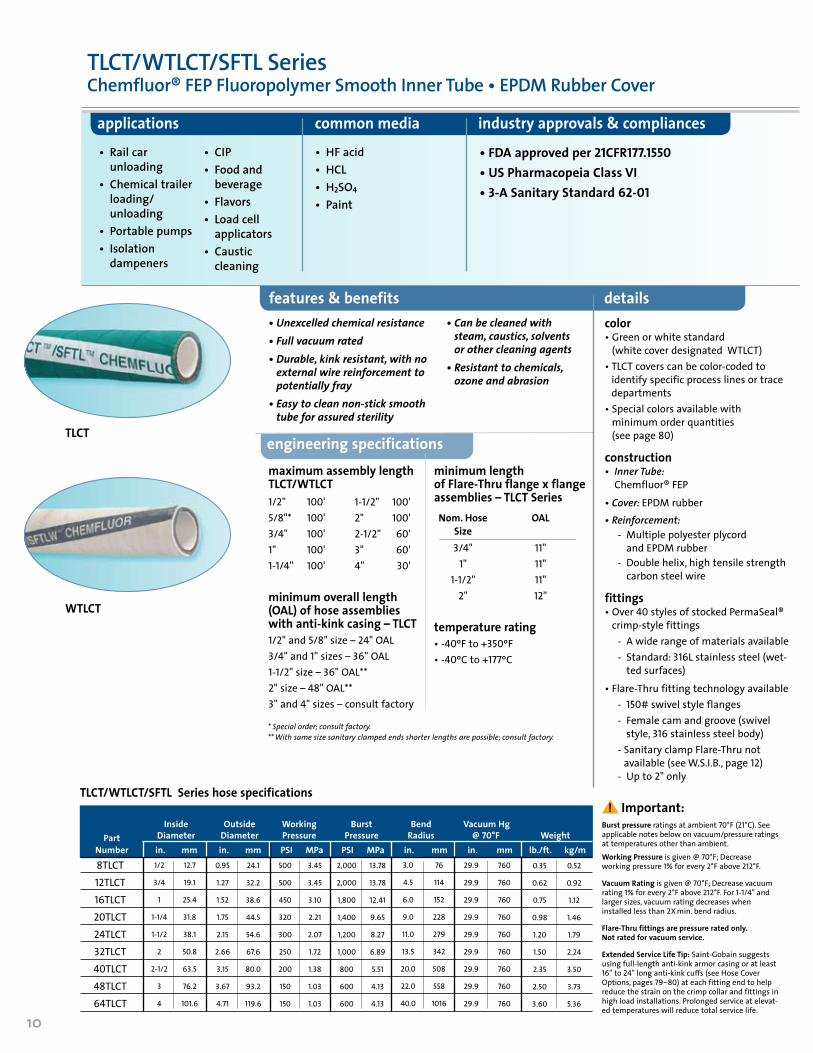
TLCT
WTLCT
applications common media industry approvals & compliances
• Rail car unloading
• Chemical trailer loading/ unloading
• Portable pumps• Isolation
dampeners
• CIP• Food and
beverage• Flavors• Load cell
applicators• Caustic
cleaning
• HF acid• HCL • H2SO4
• Paint
• FDA approved per 21CFR177.1550• US Pharmacopeia Class VI• 3-A Sanitary Standard 62-01
color • Green or white standard
(white cover designated WTLCT)• TLCT covers can be color-coded to
identify specific process lines or trace departments
• Special colors available with minimum order quantities (see page 80)
construction • Inner Tube:
Chemfluor® FEP
• Cover: EPDM rubber • Reinforcement: - Multiple polyester plycord
and EPDM rubber - Double helix, high tensile strength
carbon steel wire
fittings • Over 40 styles of stocked PermaSeal®
crimp-style fittings - A wide range of materials available - Standard: 316L stainless steel (wet-
ted surfaces)
• Flare-Thru fitting technology available - 150# swivel style flanges - Female cam and groove (swivel
style, 316 stainless steel body) - Sanitary clamp Flare-Thru not
available (see W.S.I.B., page 12) - Up to 2" only
Burst pressure ratings at ambient 70°F (21°C). See applicable notes below on vacuum/pressure ratings at temperatures other than ambient.Working Pressure is given @ 70°F; Decrease working pressure 1% for every 2°F above 212°F.
Vacuum Rating is given @ 70°F; Decrease vacuum rating 1% for every 2°F above 212°F. For 1-1/4" and larger sizes, vacuum rating decreases when installed less than 2X min. bend radius.
Flare-Thru fittings are pressure rated only. Not rated for vacuum service.
Extended Service Life Tip: Saint-Gobain suggests using full-length anti-kink armor casing or at least 16" to 24" long anti-kink cuffs (see Hose Cover Options, pages 79–80) at each fitting end to help reduce the strain on the crimp collar and fittings in high load installations. Prolonged service at elevat-ed temperatures will reduce total service life.
features & benefits details
minimum length of Flare-Thru flange x flange assemblies – TLCT Series Nom. Hose OAL Size 3/4" 11" 1" 11" 1-1/2" 11" 2" 12"
temperature rating • -40ºF to +350ºF • -40ºC to +177ºC
engineering specificationsmaximum assembly length TLCT/WTLCT1/2" 100'5/8"* 100'3/4" 100'1" 100'1-1/4" 100'
minimum overall length (OAL) of hose assemblies with anti-kink casing – TLCT1/2"and5/8"size–24"OAL3/4"and1"sizes–36"OAL1-1/2"size–36"OAL**2"size–48"OAL**3"and4"sizes–consult factory
•Unexcelledchemicalresistance•Fullvacuumrated•Durable,kinkresistant,withnoexternalwirereinforcementtopotentiallyfray
•Easytocleannon-sticksmoothtubeforassuredsterility
•Canbecleanedwithsteam,caustics,solventsorothercleaningagents
•Resistanttochemicals,ozoneandabrasion
* Special order; consult factory.** With same size sanitary clamped ends shorter lengths are possible; consult factory.
TLCT/WTLCT/SFTL SeriesChemfluor® FEP Fluoropolymer Smooth Inner Tube • EPDM Rubber Cover
TLCT/WTLCT/SFTL Series hose specifications
8TLCT12TLCT16TLCT20TLCT24TLCT32TLCT40TLCT48TLCT64TLCT
1/2
3/4
1
1-1/4
1-1/2
2
2-1/2
3
4
12.7
19.1
25.4
31.8
38.1
50.8
63.5
76.2
101.6
0.95
1.27
1.52
1.75
2.15
2.66
3.15
3.67
4.71
24.1
32.2
38.6
44.5
54.6
67.6
80.0
93.2
119.6
500
500
450
320
300
250
200
150
150
3.45
3.45
3.10
2.21
2.07
1.72
1.38
1.03
1.03
2,000
2,000
1,800
1,400
1,200
1,000
800
600
600
13.78
13.78
12.41
9.65
8.27
6.89
5.51
4.13
4.13
3.0
4.5
6.0
9.0
11.0
13.5
20.0
22.0
40.0
76
114
152
228
279
342
508
558
1016
29.9
29.9
29.9
29.9
29.9
29.9
29.9
29.9
29.9
760
760
760
760
760
760
760
760
760
0.35
0.62
0.75
0.98
1.20
1.50
2.35
2.50
3.60
0.52
0.92
1.12
1.46
1.79
2.24
3.50
3.73
5.36
1-1/2" 100'2" 100'2-1/2" 60'3" 60'4" 30'
! Important: Inside Outside Working Burst Bend Vacuum Hg Part Diameter Diameter Pressure Pressure Radius @ 70°F Weight Number in. mm in. mm PSI MPa PSI MPa in. mm in. mm lb./ft. kg/m
11
hose smooth tube
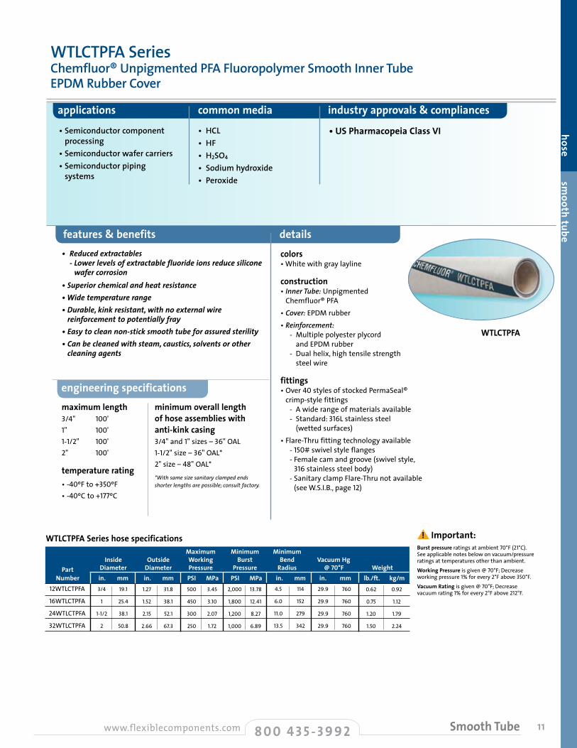
WTLCTPFA SeriesChemfluor® Unpigmented PFA Fluoropolymer Smooth Inner TubeEPDM Rubber Cover
features & benefits details
applications common media industry approvals & compliances
maximum length 3/4" 100'1" 100'1-1/2" 100'2" 100'
temperature rating• -40ºF to +350ºF• -40ºC to +177ºC
minimum overall length of hose assemblies with anti-kink casing 3/4"and1"sizes–36"OAL1-1/2"size–36"OAL*2"size–48"OAL*
colors • White with gray layline
construction • Inner Tube: Unpigmented
Chemfluor® PFA• Cover: EPDM rubber• Reinforcement:
- Multiple polyester plycord and EPDM rubber
- Dual helix, high tensile strength steel wire
fittings • Over 40 styles of stocked PermaSeal®
crimp-style fittings - A wide range of materials available - Standard: 316L stainless steel
(wetted surfaces)• Flare-Thru fitting technology available - 150# swivel style flanges - Female cam and groove (swivel style,
316 stainless steel body) - Sanitary clamp Flare-Thru not available
(see W.S.I.B., page 12)
engineering specifications
• Semiconductor component processing
• Semiconductor wafer carriers• Semiconductor piping
systems
• HCL • HF • H2SO4
• Sodium hydroxide• Peroxide
• US Pharmacopeia Class VI
Burst pressure ratings at ambient 70°F (21°C). See applicable notes below on vacuum/pressure ratings at temperatures other than ambient.Working Pressure is given @ 70°F; Decrease working pressure 1% for every 2°F above 350°F.Vacuum Rating is given @ 70°F; Decrease vacuum rating 1% for every 2°F above 212°F.
WTLCTPFA
WTLCTPFA Series hose specifications Maximum Minimum Minimum Inside Outside Working Burst Bend Vacuum Hg Part Diameter Diameter Pressure Pressure Radius @ 70°F Weight Number in. mm in. mm PSI MPa PSI MPa in. mm in. mm lb./ft. kg/m
12WTLCTPFA
16WTLCTPFA
24WTLCTPFA
32WTLCTPFA
3/4
1
1-1/2
2
19.1
25.4
38.1
50.8
1.27
1.52
2.15
2.66
31.8
38.1
52.1
67.3
500
450
300
250
3.45
3.10
2.07
1.72
2,000
1,800
1,200
1,000
13.78
12.41
8.27
6.89
4.5
6.0
11.0
13.5
114
152
279
342
29.9
29.9
29.9
29.9
760
760
760
760
0.62
0.75
1.20
1.50
0.92
1.12
1.79
2.24
• Reducedextractables -Lowerlevelsofextractablefluorideionsreducesilicone
wafercorrosion•Superiorchemicalandheatresistance•Widetemperaturerange•Durable,kinkresistant,withnoexternalwirereinforcementtopotentiallyfray
•Easytocleannon-sticksmoothtubeforassuredsterility•Canbecleanedwithsteam,caustics,solventsorothercleaningagents
*With same size sanitary clamped ends shorter lengths are possible; consult factory.
8 0 0 4 3 5 - 3 9 9 2www.flexiblecomponents.com Smooth Tube
! Important:

12 8 0 0 4 3 5 - 3 9 9 2 www.flexiblecomponents.comSmooth Tube
maximum assembly length 20' OAL
temperature rating • -40ºF to +350ºF • -40ºC to +177ºC
minimum recommended assembly length 14WSIB 12"22WSIB 15"30WSIB 18"46WSIB 24"
minimum manufacturing assembly length* 14WSIB 12"22WSIB 12"30WSIB 12"46WSIB 15"
features & benefits details
applications common media industry approvals & compliances
• Pharmaceutical processing• Chemical transfer• Acid transfer• Sensitive product transfer• Load cells• Storage vessels
• Ultra-pure water (DI)• Caustic solutions
• FDA approved per 21CFR177.1550• US Pharmacopeia Class VI• 3-A Sanitary Standard 62-01
colors • White cover with gray layline
construction • Inner Tube: Chemfluor® FEP - Tube ID matches stainless
steel sanitary tubing
• Cover: EPDM rubber
• Reinforcement: - Multiple polyester plycord
and EPDM rubber
- Dual helix, high tensile strength steel wire
fittings • Flare-Thru Fitting technology available - Clamp style (sanitary only)
- 316L stainless steel sanitary back-up ends, Flare-Thru Chemfluor® FEP fluoropolymer liner
- Male and female “I” Line® sanitary fittings also available
• W.S.I.B. hose assemblies are not rated for
vacuum process conditions.
• Solid PTFE clamp style gaskets must be used with W.S.I.B. assemblies to ensure leak-tight performance.
• W.S.I.B. sold as assembly only.
• Consult factory for additional sizes and cover color options.
engineering specifications
W.S.I.B. Series hose specifications (smooth inner bore)
W.S.I.B
•Flexibleface-to-faceChemfluor®-linedhoseassembly•Inertandchemicallyresistanttomostchemicals andreagents•S.I.B.®(SmoothInnerBore)technologyensures crevice-freefluoropolymercontactsurface - Ensuressmoothtransitionfromstainless steeltubingthroughhosefitting - Optimizesprocesstransfer - Fullflowcharacteristics - Noentrapment - Fullyself-draining - Reducedpressuredropthroughthefitting comparedtocrimp-stylefittingsystems•CleanablebyCIP,SIP•Resistanttochemicals,ozoneandabrasion
W.S.I.B. Series Hose AssembliesChemfluor® FEP Fluoropolymer Smooth Inner TubeEPDM Rubber Cover • Sanitary Tube Size I.D.
Nominal Actual Maximum Minimum Inside Inside Outside Working Bend Part Diameter Diameter Diameter Pressure Radius Number in. mm. in. mm. PSI MPa PSI MPa in. mm.
14WSIB22WSIB30WSIB46WSIB
7/8
1-3/8
1-7/8
2-7/8
22.1
34.5
47.5
72.9
7/8
1-3/8
1-7/8
2-7/8
22.1
34.3
47.5
72.9
1.50
2.10
2.63
3.70
38.10
53.34
66.80
93.98
450
300
250
150
3.10
2.07
1.72
1.03
4.75
9.00
11.50
22.00
120.65
228.60
292.10
558.80
* While these short lengths can be manufactured, little “free hose” is included in the assembly and almost no flexibility is present.
! Important:
! Important:
13
hose smooth tube
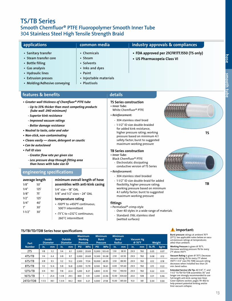
TS
TB
features & benefits details
applications common media industry approvals & compliances
• Sanitary transfer• Steam transfer core• Bottle filling• Gas analysis• Hydraulic lines• Extrusion presses• Molding/Adhesive conveying
• Chemicals• Steam• Solvents• Inks and dyes• Paint• Injectable materials• Plastisols
• FDA approved per 21CFR177.1550 (TS only)• US Pharmacopeia Class VI
average length 1/8" 50'1/4" 125'3/8" 75'1/2" 125'3/4" 40'1" 30'1-1/2" 30'
minimum overall length of hose assemblies with anti-kink casing1/4" size – 18"OAL 3/8"and 1/2" sizes – 24"OAL
temperature rating• -100ºF to +450ºF continuous;
500˚F intermittent
• -73˚C to +232˚C continuous; 260˚C intermittent
engineering specifications
TS/TB/TD/TDB Series hose specificationsBurst pressure ratings at ambient 70°F (21°C). See applicable notes below on vacu-um/pressure ratings at temperatures other than ambient.Working Pressure is given @ 70°F; Decrease working pressure 1% for every 2°F above 350°F.Vacuum Rating is given @ 70°F; Decrease vacuum rating 1% for every 2°F above 350°F. 1-1/2" size (TD, TDB) vacuum rating decreases when installed less than 2X min. bend radius.Extended Service Life Tip: All 3/4", 1", and 1-1/2" TS/TB/TD/TDB assemblies 36" and longer are strongly recommended to use full-length anti-kink casing (see Hose Cover Options section, pages 79–80) to help prevent potential kinking and/or liner vacuum collapse.
•GreaterwallthicknessofChemfluor®PTFEtube -Upto33%thickerthanmostcompetingproducts (tubewall.040minimum) -Superiorkinkresistance -Improvedvacuumratings -Betterdamageresistance•Neutraltotaste,colorandodor•Non-stick,non-contaminating•Cleanseasily—steam,detergentorcaustic•Canbeautoclaved•FullIDsizes -Greaterflowratepergivensize -LesspressuredropthroughfittingareathanhoseswithtubesizeID
TS Series construction • Inner Tube:
White Chemfluor® PTFE
• Reinforcement:
- 304stainless steel braid - 1-1/2" ID size double-braided
for added kink resistance, higher pressure rating; working pressure based on minimum 4:1 safety factor; burst to suggested maximum working pressure
TB Series construction • Inner Tube:
Black Chemfluor® PTFE - Electrostatic dissipating
conductive version of TS Series
• Reinforcement: - 304stainless steel braided - 1-1/2" ID size double-braid for added
flexibility, higher pressure rating; working pressure based on minimum 4:1 safety factor; burst to suggested maximum working pressure
fittings • PermaSeal® crimp-style - Over 40 styles in a wide range of materials - Standard: 316L stainless steel
(wetted surfaces)
Maximum Minimum Minimum Inside Outside Working Burst Bend Vacuum Hg Part Diameter Diameter Pressure Pressure Radius @ 70°F Weight Number in. mm in. mm PSI MPa PSI MPa in. mm in. mm lb./ft. kg/m
2TS4TS/TB6TS/TB8TS/TB12TS/TB16TS/TB24TD/TDB
1/8
1/4
3/8
1/2
3/4
1
1-1/2
3.2
6.4
9.5
12.4
19.1
25.4
38.1
1/4
3/8
1/2
5/8
7/8
1-1/8
1-3/4
6.1
9.7
13.2
16.8
22.4
29.5
44.2
3,000
3,000
2,500
2,000
1,200
800
900
20.69
20.69
17.24
13.79
8.27
5.51
6.21
15,000
13,500
10,000
8,500
4,800
3,200
4,000
103.43
93.08
68.95
58.61
33.10
22.06
27.58
1.50
2.50
3.50
4.00
7.50
12.00
15.00
38.10
63.50
88.90
101.60
190.50
304.60
381.00
29.9
29.9
29.9
29.9
29.9
20.0
15.0
760
760
760
760
760
508
381
0.05
0.08
0.12
0.15
0.22
0.31
0.44
0.07
0.12
0.18
0.22
0.33
0.46
0.66
! Important:
TS/TB SeriesSmooth Chemfluor® PTFE Fluoropolymer Smooth Inner Tube304 Stainless Steel High Tensile Strength Braid

14
TSS
features & benefits details
applications common media industry approvals & compliances
average length 1/4" 125'3/8" 75'1/2" 125'3/4" 40'1" 30'
temperature rating• -80ºF to +500ºF for
intermittent service• -62ºC to +260ºC for
intermittent service• +450ºF (+232˚C) continuous
service
colors • Natural silicone
construction • I nner Tube: Chemfluor®
white PTFE• Cover: platinum-cured
silicone• Reinforcement: 304 stainless
steel braid
fittings • PermaSeal® crimp-style - Over 40 styles in a wide range
of materials - Standard: 316L stainless steel
(wetted surfaces)
engineering specifications
• Wash down hoses• Transfer and equipment lines• Filling equipment
• Caustic solutions• Ultra-pure water (DI)• Clean steam (low pressure)• Mascara/creams/lotions
• FDA approved per 21CFR177.1550 • US Pharmacopeia Class VI• 3-A Sanitary Standard 62-01
TSS Series hose specificationsBurst pressure ratings at ambient 70°F (21°C). See applicable notes below on vacuum/pressure ratings at temperatures other than ambient.Working Pressure is given @ 70°F; Decrease working pressure 1% for every 2°F above 350°F.Vacuum Rating is given @ 70°F; Decrease vacuum rating 1% for every 2°F above 350°F. 1" size vacuum rating decreases when installed less than 2X min. bend radius.
•Pureplatinum-curedsiliconeoutercoverextrudedoverTSSerieshose
•Permitseasycleaning•Ultra-smoothoutercoverensuresnoparticleentrapmentinstainlesssteelbraids
•Reducesbraidfraying•Helpsinsulateexteriorfrom“burn”potential•Singlecrimpcollarlocksinhosebarbandsealsoffsiliconecover;eliminatesbulkysecondaryring
•Extrudedcoveris“locked”ontostainlesssteelbraid,willnotmovewhenhandled
•ConsultfactoryforspecialorderTBSeries(conductive)versionwithsiliconecover
•Canbeautoclaved
TSS SeriesChemfluor® PTFE Fluoropolymer Smooth Inner Tube Stainless Steel Braid • Silicone Cover
Maximum Minimum Minimum Inside Outside Working Burst Bend Vacuum Hg Part Diameter Diameter Pressure Pressure Radius @ 70°F Weight Number in. mm in. mm PSI MPa PSI MPa in. mm in. mm lb./ft. kg/m
4TSS6TSS8TSS12TSS16TSS
1/4
3/8
1/2
3/4
1
6.4
9.5
12.7
19.1
25.4
1/2
9/16
3/4
1
1-1/4
11.6
15.2
19.2
25.0
31.6
3,000
2,500
2,000
1,200
800
20.69
17.24
13.79
8.27
5.52
13,500
10,000
8,500
4,800
3,200
93.08
68.95
58.61
33.10
22.06
2.50
3.50
4.00
7.50
12.00
63.50
88.90
101.60
190.50
304.80
29.9
29.9
29.9
29.9
29.9
760
760
760
760
760
0.12
0.18
0.25
0.30
0.40
0.18
0.27
0.37
0.45
0.60
8 0 0 4 3 5 - 3 9 9 2 www.flexiblecomponents.comSmooth Tube
! Important:
TH Series fitting options
J.I.C Female SwivelStyle 02
Male NPTStyle 03
Female NPTStyle 06
J.I.C. Adapter Union Male Style 08
O-RingStyle 33
15
engineering specifications details
applications common media features & benefits
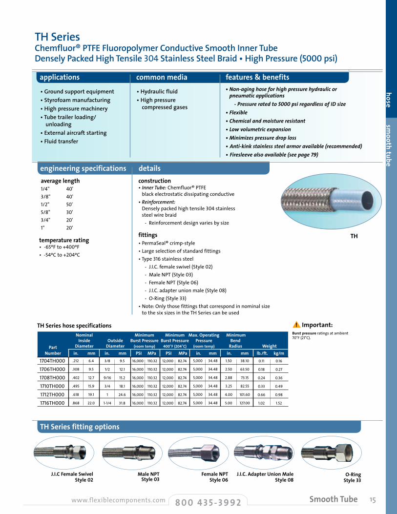
• Ground support equipment• Styrofoam manufacturing• High pressure machinery• Tube trailer loading/ unloading• External aircraft starting• Fluid transfer
• Hydraulic fluid• High pressure compressed gases
•Non-aginghoseforhighpressurehydraulicorpneumaticapplications
-Pressureratedto5000psiregardlessofIDsize•Flexible•Chemicalandmoistureresistant•Lowvolumetricexpansion•Minimizespressuredroploss•Anti-kinkstainlesssteelarmoravailable(recommended)•Firesleevealsoavailable(seepage79)
average length 1/4" 40'3/8" 40'1/2" 50'5/8" 30'3/4" 20'1" 20'
temperature rating • -65ºF to +400ºF• -54ºC to +204ºC
TH Series hose specifications
TH
hose smooth tube
Nominal Minimum Minimum Max. Operating Minimum Inside Outside Burst Pressure Burst Pressure Pressure Bend Part Diameter Diameter (room temp) 400˚F (204˚C) (room temp) Radius Weight Number in. mm in. mm PSI MPa PSI MPa in. mm in. mm lb./ft. kg/m
1704TH0001706TH0001708TH0001710TH0001712TH0001716TH000
.212
.308
.402
.495
.618
.868
6.4
9.5
12.7
15.9
19.1
22.0
3/8
1/2
9/16
3/4
1
1-1/4
9.5
12.1
15.2
18.1
24.6
31.8
16,000
16,000
16,000
16,000
16,000
16,000
110.32
110.32
110.32
110.32
110.32
110.32
12,000
12,000
12,000
12,000
12,000
12,000
82.74
82.74
82.74
82.74
82.74
82.74
5,000
5,000
5,000
5,000
5,000
5,000
34.48
34.48
34.48
34.48
34.48
34.48
1.50
2.50
2.88
3.25
4.00
5.00
38.10
63.50
73.15
82.55
101.60
127.00
0.11
0.18
0.24
0.33
0.66
1.02
0.16
0.27
0.36
0.49
0.98
1.52
Burst pressure ratings at ambient 70°F (21°C).
construction • Inner Tube: Chemfluor® PTFE
black electrostatic dissipating conductive• Reinforcement:
Densely packed high tensile 304 stainless steel wire braid
- Reinforcement design varies by size
fittings• PermaSeal® crimp-style• Large selection of standard fittings • Type 316stainless steel - J.I.C. female swivel (Style 02) - Male NPT (Style 03) - Female NPT (Style 06) - J.I.C. adapter union male (Style 08) - O-Ring (Style 33)• Note: Only those fittings that correspond in nominal size
to the six sizes in the TH Series can be used
8 0 0 4 3 5 - 3 9 9 2www.flexiblecomponents.com Smooth Tube
! Important:
TH SeriesChemfluor® PTFE Fluoropolymer Conductive Smooth Inner Tube Densely Packed High Tensile 304 Stainless Steel Braid • High Pressure (5000 psi)

16
features & benefits details
applications common media
•Excellentchemicalresistance•Highpurity,non-contaminating•Non-sticksurfaceprovidesmaximumflowrate,minimizespotentialcontamination
•Notsubjecttocorrosion,pinholingorflexcracking•Themostflexiblesmooth-tubefluoropolymerhoseofitstype•Allstainlesssteelconstruction(exceptliner)
construction • Inner tube: Chemfluor® FEP • Inner housing: 304 stainless steel
annular inner hose (standard) - 316L stainless steel inner
hose available• Reinforcement: 304 stainless steel
outer braid• Vent holes: 1/8" diameter vent holes - One per end (for permeation and leak
detection)
cover option • Custom EPDM cover (call factory for details)
fittings • Flare-Thru fitting technology available• Standard flanges:150# epoxy-coated
carbon steel lap-joint style - 300# flanges available for interface
connection only - 304 and 316L stainless steel
flanges available (optional)• Female cam and groove (swivel style) - 316 stainless steel body - Chemfluor® PFA encapsulated
gaskets installed in assembly (standard)
• 1", 1-1/2" and 2" sanitary clamp style available
• See page 36 for more on Flare-Thru fitting technology
• Tank car and truck loading and unloading• Weigh cells/tank isolation• Pump connectors• Food and beverage• CIP lines
• Sulfuric acid base chemicals• Product chemicals• Syrups/food products• Caustic
industry approvals & compliances• 3-A Sanitary Standard 62-01 ( EPDM cover option only)
MTL
MTL Series Hose AssembliesStainless Steel Braided Metal HoseChemfluor® FEP Fluoropolymer Smooth Inner Tube • Flare-Thru Fittings
MTL Series hose specifications Maximum Minimum Inside Outside Working Bend Vacuum Hg Part Nominal Size Diameter Diameter Pressure Radius @ 70˚F Number* in. mm in. mm in. mm PSI MPa in. mm in. mm
Replace XXXX with 1010 for sanitary clamp fitting (1", 1-1/2", and 2" only). Replace XXXX with 1212 for 150# swivel flanges (1" to 8"). Replace XXXX with 1616 for female swivel cam and grooves (1" to 3" only)
16MTLXXXXSCT-“L”
24MTLXXXXSCT-“L”
32MTLXXXXSCT-“L”
48MTLXXXXSCT-“L”
64MTLXXXXSCT-“L”
96MTLXXXXSCT-“L”
128MTLXXXXSCT-“L”
1
1-1/2
2
3
4
6
8
25.4
38.1
50.8
76.2
101.6
152.4
203.2
7/8
1-3/8
1-3/4
2-3/4
3-3/4
5-3/4
7-3/8
21.8
35.6
45.7
71.1
96.5
147.3
198.1
1-3/8
2-1/8
2-1/2
4
5
7-1/8
9-3/8
34.3
53.3
64.8
102.9
127.0
180.3
237.5
275
275
275
275
250
200
185
1.90
1.90
1.90
1.90
1.72
1.38
1.28
10.00
12.00
18.00
28.00
42.00
60.00
84.00
254.00
304.80
457.20
711.20
1066.80
1524.00
2133.60
29.9
29.9
29.9
29.9
29.9
22.0
22.0
760
760
760
760
760
559
559
8 0 0 4 3 5 - 3 9 9 2 www.flexiblecomponents.comSmooth Tube
! Important:
maximum length 1"-4" 20' max. 6"-8" 10' max.
temperature rating • -65ºF to +350ºF• -54ºC to +177ºC
vacuum rating • 29.9 in. Hg@70ºF
minimum length of Flare-Thru flange x flange assemblies
Nom. Hose OAL Size
1" 11" 1-1/2" 11" 2" 12" 3" 12" 4" 12" 6" 14" 8" 14"
engineering specifications
NEW!

MTL Series Flare-Thru Fitting Styles
17
hose smooth tube
details
For more information on these fittings, see pages 37-39
• For fitting length dimensions, see charts on pages 37-39
• For combination of Flare-Thru fitting styles on MTL Series hose assemblies, please consult factory
• Not all fitting combinations and sizes of hoses can be manufactured
• Crimp style fittings may be installed on certain size MTL hose assemblies for special interface to all-metal or solid plastic piping systems utilizing male or female pipe threads; consult factory for availability and delivery
• Minimum and maximum length of hose assemblies listed on preceding page
Working Working Minimum Nominal Inside Outside Pressure Pressure Bend Vacuum Hg Part Size Diameter Diameter 70˚F 350˚F Radius @ 70˚F Number in. mm in. mm in. mm PSI MPa PSI MPa in. mm in. mm
16MTL1010S6FT-“L”
24MTL1010S6FT-“L”
32MTL1010S6FT-“L”
1
1-1/2
2
25.4
38.1
50.8
7/8
1-3/8
1-3/4
21.8
35.6
45.7
1-3/8
2-1/8
2-1/2
34.3
53.3
64.8
250
250
250
1.72
1.72
1.72
250
250
250
1.72
1.72
1.72
10.00
12.00
18.00
254.00
304.80
457.20
MTL Series: Sanitary Clamp Style Assemblies
29.9
29.9
29.9
760
760
760
Working Working Minimum Nominal Inside Outside Pressure Pressure Bend Vacuum Hg Part Size Diameter Diameter 70˚F 350˚F Radius @ 70˚F Number in. mm in. mm in. mm PSI MPa PSI MPa in. mm in. mm
Codes for materials: C = Epoxy coated carbon steel 150# flange. 4 = 304 stainless steel lap-joint flange 150# flange. 6 = 316 stainless steel lap-joint flange 150# flange.
16MTL1212SCT-“L”
24MTL1212SCT-“L”
32MTL1212SCT-“L”
48MTL1212SCT-“L”
64MTL1212SCT-“L”
96MTL1212SCT-“L”
128MTL1212SCT-“L”
1
1-1/2
2
3
4
6
8
25.4
38.1
50.8
76.2
101.6
152.4
203.2
7/8
1-3/8
1-3/4
2-3/4
3-3/4
5-3/4
7-3/8
21.8
35.6
45.7
71.1
96.5
147.3
198.1
1-3/8
2-1/8
2-1/2
4
5
7-1/8
9-3/8
34.3
53.3
64.8
102.9
127.0
180.3
237.5
275
275
275
275
250
200
185
1.90
1.90
1.90
1.90
1.72
1.38
1.28
200
200
200
200
190
160
160
1.38
1.38
1.38
1.38
1.31
1.10
1.10
10.00
12.00
18.00
28.00
42.00
60.00
84.00
254.00
304.80
457.20
711.20
1,066.80
1,524.00
2,133.60
MTL Series: 150# Flanged Assemblies
29.9
29.9
29.9
29.9
29.9
22.0
22.0
760
760
760
760
760
559
559
Working Working Minimum Nominal Inside Outside Pressure Pressure Bend Vacuum Hg Part Size Diameter Diameter 70˚F 350˚F Radius @ 70˚F Number in. mm in. mm in. mm PSI MPa PSI MPa in. mm in. mm
Consult factory for these fittings
16MTL1616S6FT-“L”
24MTL1616S6FT-“L”
32MTL1616S6FT-“L”
48MTL1616S6FT-“L”
1
1-1/2
2
3
25.4
38.1
50.8
76.2
7/8
1-3/8
1-3/4
2-3/4
21.8
35.6
45.7
71.1
1-3/8
2-1/8
2-1/2
4
34.3
53.3
64.8
102.9
250
250
250
150
1.72
1.72
1.72
1.03
250
250
250
150
1.72
1.72
1.72
1.03
10.00
12.00
18.00
28.00
254.00
304.80
457.20
711.20
MTL Series: Female Cam and Groove (Swivel) Assemblies
29.9
29.9
29.9
29.9
760
760
760
760
! Important:
Sanitary Clamp Style
Female Cam and Groove(Swivel)
150# Flanged
18
features & benefits details
applications common media
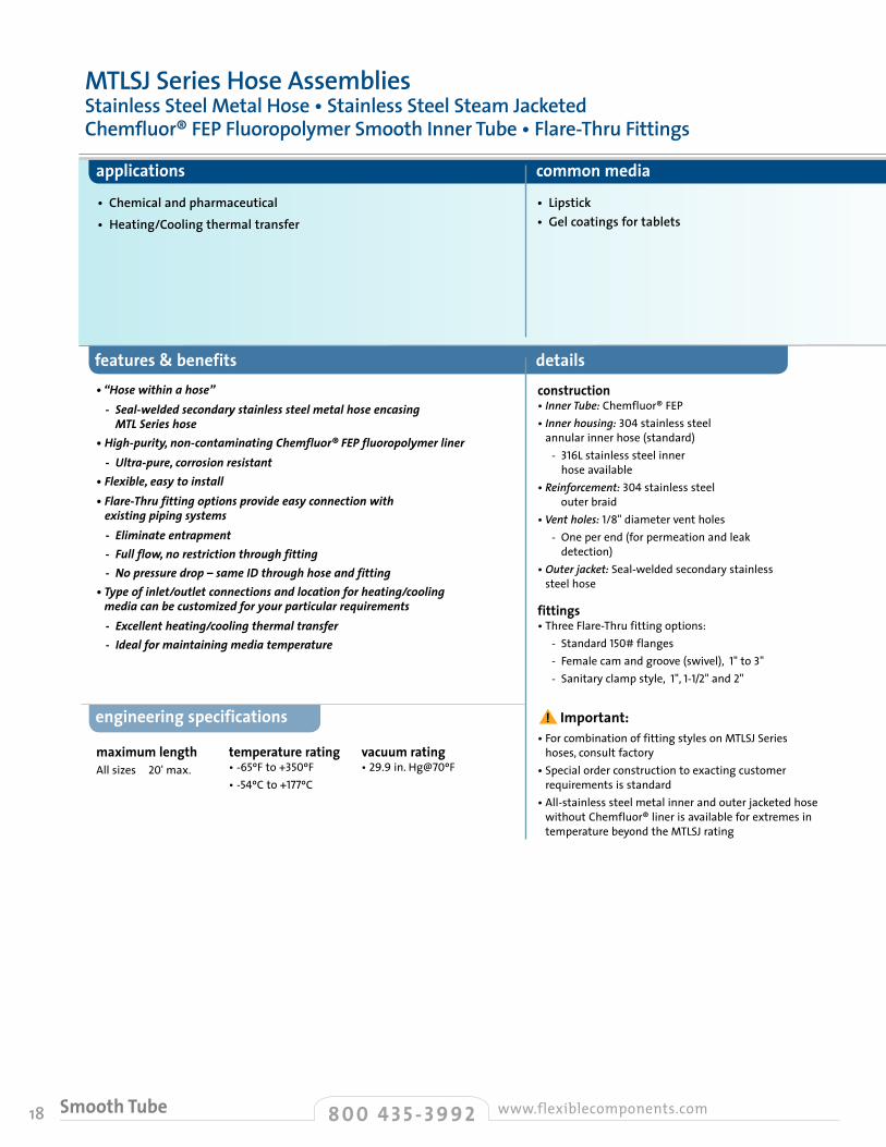
• Chemical and pharmaceutical• Heating/Cooling thermal transfer
• Lipstick• Gel coatings for tablets
construction • Inner Tube: Chemfluor® FEP • Inner housing: 304 stainless steel
annular inner hose (standard) - 316L stainless steel inner
hose available• Reinforcement: 304 stainless steel
outer braid• Vent holes: 1/8" diameter vent holes - One per end (for permeation and leak
detection)• Outer jacket: Seal-welded secondary stainless
steel hose
fittings • Three Flare-Thru fitting options: - Standard 150# flanges - Female cam and groove (swivel), 1" to 3" - Sanitary clamp style, 1", 1-1/2" and 2"
• For combination of fitting styles on MTLSJ Series
hoses, consult factory• Special order construction to exacting customer
requirements is standard• All-stainless steel metal inner and outer jacketed hose
without Chemfluor® liner is available for extremes in temperature beyond the MTLSJ rating
maximum length All sizes 20' max.
temperature rating • -65ºF to +350ºF• -54ºC to +177ºC
vacuum rating • 29.9 in. Hg@70ºF
engineering specifications
•“Hosewithinahose” -Seal-weldedsecondarystainlesssteelmetalhoseencasing
MTLSerieshose•High-purity,non-contaminatingChemfluor®FEPfluoropolymerliner -Ultra-pure,corrosionresistant•Flexible,easytoinstall•Flare-Thrufittingoptionsprovideeasyconnectionwithexistingpipingsystems
-Eliminateentrapment -Fullflow,norestrictionthroughfitting -Nopressuredrop–sameIDthroughhoseandfitting•Typeofinlet/outletconnectionsandlocationforheating/coolingmediacanbecustomizedforyourparticularrequirements
-Excellentheating/coolingthermaltransfer -Idealformaintainingmediatemperature
MTLSJ Series Hose AssembliesStainless Steel Metal Hose • Stainless Steel Steam Jacketed Chemfluor® FEP Fluoropolymer Smooth Inner Tube • Flare-Thru Fittings
8 0 0 4 3 5 - 3 9 9 2 www.flexiblecomponents.comSmooth Tube
! Important:
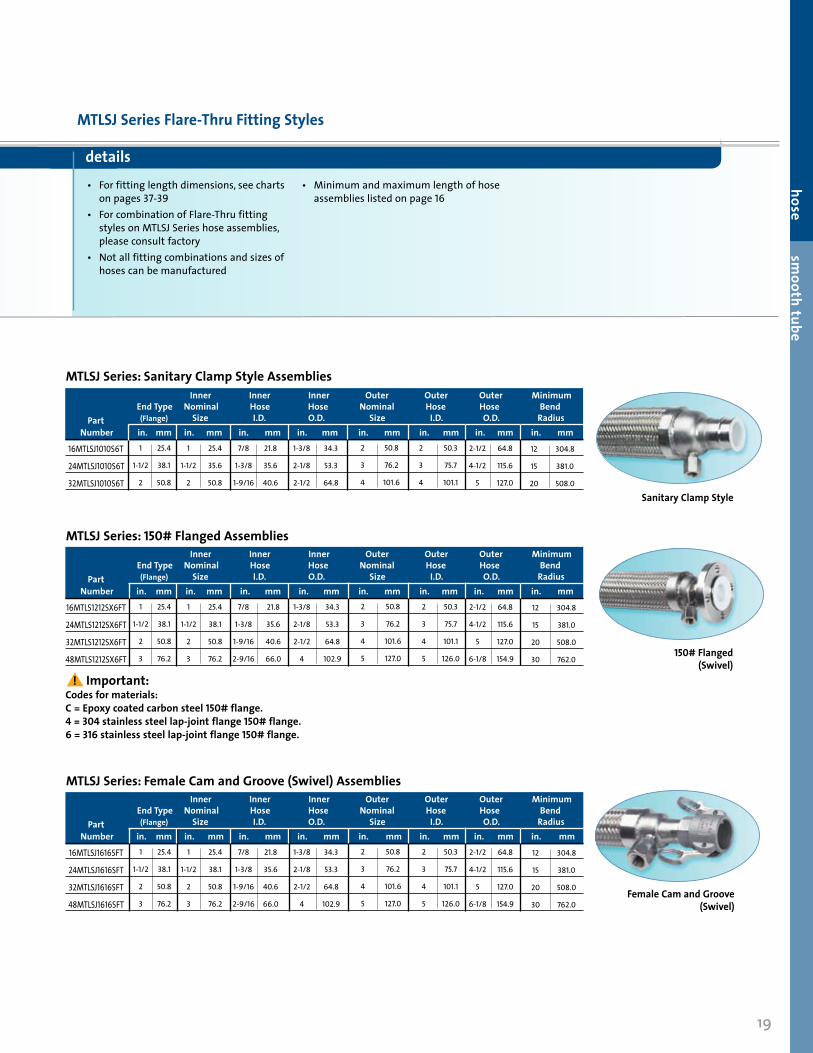
details• For fitting length dimensions, see charts
on pages 37-39• For combination of Flare-Thru fitting
styles on MTLSJ Series hose assemblies, please consult factory
• Not all fitting combinations and sizes of hoses can be manufactured
• Minimum and maximum length of hose assemblies listed on page 16
19
hose smooth tube
MTLSJ Series Flare-Thru Fitting Styles
Inner Inner Inner Outer Outer Outer Minimum End Type Nominal Hose Hose Nominal Hose Hose Bend Part (Flange) Size I.D. O.D. Size I.D. O.D. Radius Number in. mm in. mm in. mm in. mm in. mm in. mm in. mm in. mm
16MTLSJ1010S6T
24MTLSJ1010S6T
32MTLSJ1010S6T
1
1-1/2
2
25.4
38.1
50.8
1
1-1/2
2
25.4
35.6
50.8
7/8
1-3/8
1-9/16
21.8
35.6
40.6
1-3/8
2-1/8
2-1/2
34.3
53.3
64.8
2
3
4
50.8
76.2
101.6
2
3
4
50.3
75.7
101.1
MTLSJ Series: Sanitary Clamp Style Assemblies
2-1/2
4-1/2
5
64.8
115.6
127.0
12
15
20
304.8
381.0
508.0
Sanitary Clamp Style
Inner Inner Inner Outer Outer Outer Minimum End Type Nominal Hose Hose Nominal Hose Hose Bend Part (Flange) Size I.D. O.D. Size I.D. O.D. Radius Number in. mm in. mm in. mm in. mm in. mm in. mm in. mm in. mm
Codes for materials: C = Epoxy coated carbon steel 150# flange. 4 = 304 stainless steel lap-joint flange 150# flange. 6 = 316 stainless steel lap-joint flange 150# flange.
16MTLS1212SX6FT
24MTLS1212SX6FT
32MTLS1212SX6FT
48MTLS1212SX6FT
1
1-1/2
2
3
25.4
38.1
50.8
76.2
1
1-1/2
2
3
25.4
38.1
50.8
76.2
7/8
1-3/8
1-9/16
2-9/16
21.8
35.6
40.6
66.0
1-3/8
2-1/8
2-1/2
4
34.3
53.3
64.8
102.9
2
3
4
5
50.8
76.2
101.6
127.0
2
3
4
5
50.3
75.7
101.1
126.0
MTLSJ Series: 150# Flanged Assemblies
2-1/2
4-1/2
5
6-1/8
64.8
115.6
127.0
154.9150# Flanged
(Swivel)
12
15
20
30
304.8
381.0
508.0
762.0
Inner Inner Inner Outer Outer Outer Minimum End Type Nominal Hose Hose Nominal Hose Hose Bend Part (Flange) Size I.D. O.D. Size I.D. O.D. Radius Number in. mm in. mm in. mm in. mm in. mm in. mm in. mm in. mm
16MTLSJ1616SFT
24MTLSJ1616SFT
32MTLSJ1616SFT
48MTLSJ1616SFT
1
1-1/2
2
3
25.4
38.1
50.8
76.2
1
1-1/2
2
3
25.4
38.1
50.8
76.2
7/8
1-3/8
1-9/16
2-9/16
21.8
35.6
40.6
66.0
1-3/8
2-1/8
2-1/2
4
34.3
53.3
64.8
102.9
2
3
4
5
50.8
76.2
101.6
127.0
2
3
4
5
50.3
75.7
101.1
126.0
MTLSJ Series: Female Cam and Groove (Swivel) Assemblies
2-1/2
4-1/2
5
6-1/8
64.8
115.6
127.0
154.9
12
15
20
30
304.8
381.0
508.0
762.0
! Important:
Female Cam and Groove (Swivel)

20
features & benefits details
applications common media industry approvals & compliances• Sanitary transfer• Food, flavors and syrups• Solvent transfer• Drain and sample lines
• Base chemicals• Corn syrup• Hexane (TBOB)• Product transfer• Caustic solutions
• USDA• FDA (TWOB only)• US Pharmacopeia Class VI
construction • Inner Tube - TWOB: Chemfluor® white PTFE - TBOB: Chemfluor® black PTFE
electrostatic dissipating conductive• Reinforcement: 316 stainless steel braid - Other braid options available: - Polypropylene –
TWOY/TBOY, see page 21 - PVDF (Kynar®) –
TWOK/TBOK, see page 22
fittings• PermaSeal® crimp-style - Over 40 styles• Flare-Thru fitting technology available: - 150# lap-joint style flanged - Female cam and groove - Sanitary clamp style - 1/2" mini sanitary Flare-Thru
available using 3/8" ID open pitch hose
• Fitting details begin on page 33
• Hose assemblies may be autoclaved; however, flare faces of Flare-Thru fittings must be clamped down to prevent damage to sealing surface
maximum length1/2" 100' 3/4" 70' 1" 65' 1-1/4" 45' 1-1/2" 70' 2" 50' 2-1/2" 30' 3" 30' 4" 20'
engineering specifications
Burst pressure ratings at ambient 70°F (21°C). See applicable notes below on vacuum/pressure ratings at temperatures other than ambient.Working Pressure is given @ 70ºF; decrease working pressure 1% for every 2ºF above 250ºF.Vacuum Rating is given @ 70ºF @ 2X minimum bend radius; decrease vacuum rating 1% for every 2ºF above 250ºF. Vacuum rating decreases when installed @ less than 2X minimum bend radius. TWOBHV/TBOBHV Series (heavy duty vacuum option) allows full vacuum ratings for 1-1/2", 2" and 2-1/2" sizes up to 350ºF; decrease vacuum rating 1% for every 2ºF above 350ºF. Vacuum rating @ less than 2x minimum bend radius: 1-1/4" = 26" Hg; 1-1/2" = 25" Hg; 2" = 20" Hg; 2-1/2" = 17" Hg; 3" = 20" Hg; 4" = 17" Hg.Extended Service Life Tip: Saint-Gobain suggests using full-length anti-kink armor casing or at least 16" to 24" long anti-kink cuffs (see Hose Cover Options, pages 79-80) at each fitting end to help reduce the strain on the crimp collar and fittings in high load installations. Prolonged service at elevated temperatures will reduce total service life.
TWOBHV/TBOBHV Series• Fully rated vacuum hose• Recommended for full vacuum applications• Should always be used for 2-1/2", 3" and 4" I.D. assemblies
Chemfluor®PTFEinnertube•Excellentchemicalresistance•Compatiblewithalmostallmaterials•Rounded,open-pitchhelicalconvolutionsshapedtoensuresmoothproductflow
•Non-sticksurface,easytoclean(steam,caustics,solventsorothercleaningagents)
•Assuredsterility•Easytoflex,yetwon’tflattenwhenbent
Chemfluor®blackPTFEelectrostaticdissipatingconductiveinnertube•Co-extrusiondesignwithminuteamountofcarbonaddedtoinnerportionofthick-wallconstruction
•Processedtopreventchemicalleachingorfrictioncontamination
•Chemfluor®PTFEpropertiesarecompletelymaintained
TWOB/TBOB/TWOBHV/TBOBHV SeriesChemfluor® PTFE Fluoropolymer Helically Convoluted Inner Tube Stainless Steel Braid • Open Pitch
TWOB/TBOB/TWOBHV/TBOBHV Series hose specifications
8TWOB/TBOB
12TWOB/TBOB
16TWOB/TBOB
20TWOB/TBOB
24TWOB/TBOB/HV
32TWOB/TBOB/HV
40TWOB/TBOB/HV
48TWOB/TBOB/HV
64TWOB/TBOB/HV
1/2
3/4
1
1-1/4
1-1/2
2
2-1/2
3
4
12.7
19.1
25.4
31.8
38.1
50.8
63.5
76.2
101.6
3/4
1-1/8
1-1/4
1-5/8
2
2-1/2
3-1/8
3-7/8
5
19.1
28.6
31.8
41.3
50.8
63.5
79.4
98.4
127.0
500
425
350
337
275
250
212
175
150
3.45
2.93
2.41
2.32
1.90
1.72
1.46
1.21
1.03
2,000
1,700
1,400
1,350
1,100
1,000
850
700
600
13.79
11.72
9.65
9.31
7.58
6.90
5.86
4.83
4.14
2.00
2.75
4.00
5.50
7.00
8.50
13.00
14.00
16.00
50.80
69.85
101.60
139.70
177.80
215.90
330.20
355.60
406.40
25.0
25.0
25.0
25.0
29.9
29.9
29.9
29.9
29.9
635
635
635
635
760
760
760
760
760
0.20
0.30
0.40
0.70
0.75
1.05
1.35
1.75
2.10
0.30
0.45
0.60
1.04
1.12
1.56
2.01
2.61
3.13
temperature rating• -100ºF to +450ºF• -73ºC to +232ºC
! Important:
! Important: *Add HV to indicate Vacuum Rated Series
! Important:
TBOB
TWOBHV/TBOBHV
TWOB
Maximum Minimum Minimum Inside Outside Working Burst Bend Vacuum Hg Part Diameter Diameter Pressure Pressure Radius @ 70°F Weight Number* in. mm in. mm PSI MPa PSI MPa in. mm in. mm lb./ft. kg/m
21
hose convoluted
3/4" 70' 1" 65' 1-1/4" 45' 1-1/2" 70' 2" 50' 2-1/2" 30' 3" 30' 4" 20'
features & benefits details
applications common media industry approvals & compliances
maximum length
engineering specifications
• Sanitary transfer• Food, flavors and syrups• Solvent transfer• Drain and sample lines• Semi-transparent sight gauges• Corrosive environments
• Base chemicals• Corn syrup• Hexane (TBOY)• Product transfer• Caustic solutions
• USDA• FDA (TWOY only)• US Pharmacopeia Class VI
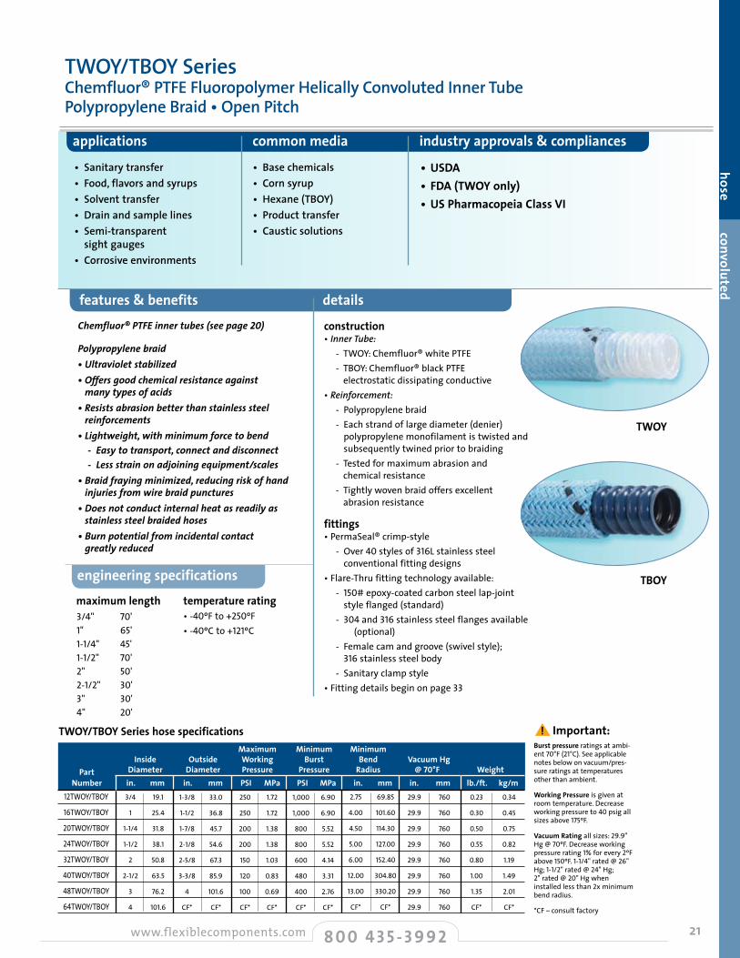
TWOY/TBOY Series hose specificationsBurst pressure ratings at ambi-ent 70°F (21°C). See applicable notes below on vacuum/pres-sure ratings at temperatures other than ambient.
Working Pressure is given at room temperature. Decrease working pressure to 40 psig all sizes above 175ºF.
Vacuum Rating all sizes: 29.9" Hg @ 70ºF. Decrease working pressure rating 1% for every 2ºF above 150ºF. 1-1/4" rated @ 26" Hg; 1-1/2" rated @ 24" Hg; 2" rated @ 20" Hg when installed less than 2x minimum bend radius.
*CF – consult factory
TWOY
TBOY
Chemfluor®PTFEinnertubes(seepage20)
Polypropylenebraid•Ultravioletstabilized•Offersgoodchemicalresistanceagainstmanytypesofacids
•Resistsabrasionbetterthanstainlesssteelreinforcements
•Lightweight,withminimumforcetobend -Easytotransport,connectanddisconnect -Lessstrainonadjoiningequipment/scales•Braidfrayingminimized,reducingriskofhandinjuriesfromwirebraidpunctures
•Doesnotconductinternalheatasreadilyasstainlesssteelbraidedhoses
•Burnpotentialfromincidentalcontactgreatlyreduced
construction • Inner Tube: - TWOY: Chemfluor® white PTFE - TBOY: Chemfluor® black PTFE
electrostatic dissipating conductive• Reinforcement: - Polypropylene braid - Each strand of large diameter (denier)
polypropylene monofilament is twisted and subsequently twined prior to braiding
- Tested for maximum abrasion and chemical resistance
- Tightly woven braid offers excellent abrasion resistance
fittings • PermaSeal® crimp-style - Over40styles of 316L stainless steel
conventional fitting designs• Flare-Thru fitting technology available: - 150# epoxy-coated carbon steel lap-joint
style flanged (standard) - 304 and 316 stainless steel flanges available
(optional) - Female cam and groove (swivel style);
316 stainless steel body - Sanitary clamp style• Fitting details begin on page33
TWOY/TBOY SeriesChemfluor® PTFE Fluoropolymer Helically Convoluted Inner Tube Polypropylene Braid • Open Pitch
temperature rating• -40ºF to +250ºF• -40ºC to +121ºC
Maximum Minimum Minimum Inside Outside Working Burst Bend Vacuum Hg Part Diameter Diameter Pressure Pressure Radius @ 70°F Weight Number in. mm in. mm PSI MPa PSI MPa in. mm in. mm lb./ft. kg/m12TWOY/TBOY
16TWOY/TBOY
20TWOY/TBOY
24TWOY/TBOY
32TWOY/TBOY
40TWOY/TBOY
48TWOY/TBOY
64TWOY/TBOY
3/4
1
1-1/4
1-1/2
2
2-1/2
3
4
19.1
25.4
31.8
38.1
50.8
63.5
76.2
101.6
1-3/8
1-1/2
1-7/8
2-1/8
2-5/8
3-3/8
4
CF*
33.0
36.8
45.7
54.6
67.3
85.9
101.6
CF*
250
250
200
200
150
120
100
CF*
1.72
1.72
1.38
1.38
1.03
0.83
0.69
CF*
1,000
1,000
800
800
600
480
400
CF*
6.90
6.90
5.52
5.52
4.14
3.31
2.76
CF*
2.75
4.00
4.50
5.00
6.00
12.00
13.00
CF*
69.85
101.60
114.30
127.00
152.40
304.80
330.20
CF*
29.9
29.9
29.9
29.9
29.9
29.9
29.9
29.9
760
760
760
760
760
760
760
760
0.23
0.30
0.50
0.55
0.80
1.00
1.35
CF*
0.34
0.45
0.75
0.82
1.19
1.49
2.01
CF*
8 0 0 4 3 5 - 3 9 9 2www.flexiblecomponents.com Convoluted
! Important:
22
features & benefits details
applications common media industry approvals & compliances
• Sanitary transfer• Food, flavors and syrups• Solvent transfer• Drain and sample lines• Semi-transparent sight gauges• Corrosive environments (external)• Liquid chlorine and bromine transfer• Chlorinated fluid and gas transfer
• Base chemicals• Corn syrup• Hexane (TBOK)• Product transfer• Caustic solutions• Liquid chlorine• Bromine
• USDA• FDA (TWOK only)• US Pharmacopeia Class VI
engineering specifications
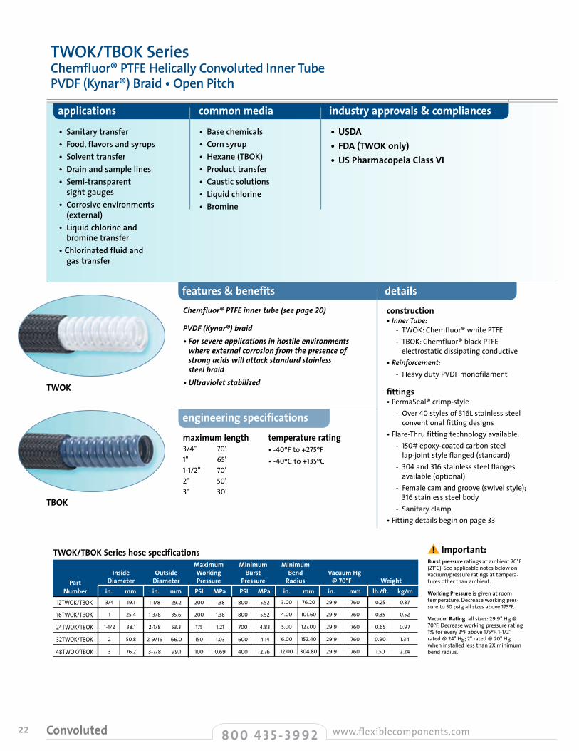
Burst pressure ratings at ambient 70°F (21°C). See applicable notes below on vacuum/pressure ratings at tempera-tures other than ambient.
Working Pressure is given at room temperature. Decrease working pres-sure to 50 psig all sizes above 175ºF.
Vacuum Rating all sizes: 29.9" Hg @ 70ºF. Decrease working pressure rating 1% for every 2ºF above 175ºF. 1-1/2" rated @ 24" Hg; 2" rated @ 20" Hg when installed less than 2X minimum bend radius.
Chemfluor®PTFEinnertube(seepage20)
PVDF(Kynar®)braid•Forsevereapplicationsinhostileenvironmentswhereexternalcorrosionfromthepresenceofstrongacidswillattackstandardstainlesssteelbraid
•Ultravioletstabilized
construction • Inner Tube:
- TWOK: Chemfluor® white PTFE - TBOK: Chemfluor® black PTFE
electrostatic dissipating conductive• Reinforcement: - Heavy duty PVDF monofilament
fittings • PermaSeal® crimp-style - Over40 styles of 316L stainless steel
conventional fitting designs• Flare-Thru fitting technology available: - 150# epoxy-coated carbon steel
lap-joint style flanged (standard) - 304and 316stainless steel flanges
available (optional) - Female cam and groove (swivel style);
316stainless steel body - Sanitary clamp• Fitting details begin on page33
TWOK
TBOK
TWOK/TBOK SeriesChemfluor® PTFE Helically Convoluted Inner Tube PVDF (Kynar®) Braid • Open Pitch
maximum length3/4" 70' 1" 65' 1-1/2" 70' 2" 50' 3" 30'
temperature rating• -40ºF to +275ºF• -40ºC to +135ºC
Maximum Minimum Minimum Inside Outside Working Burst Bend Vacuum Hg Part Diameter Diameter Pressure Pressure Radius @ 70°F Weight Number in. mm in. mm PSI MPa PSI MPa in. mm in. mm lb./ft. kg/m
12TWOK/TBOK
16TWOK/TBOK
24TWOK/TBOK
32TWOK/TBOK
48TWOK/TBOK
3/4
1
1-1/2
2
3
19.1
25.4
38.1
50.8
76.2
1-1/8
1-3/8
2-1/8
2-9/16
3-7/8
29.2
35.6
53.3
66.0
99.1
200
200
175
150
100
1.38
1.38
1.21
1.03
0.69
800
800
700
600
400
5.52
5.52
4.83
4.14
2.76
3.00
4.00
5.00
6.00
12.00
76.20
101.60
127.00
152.40
304.80
29.9
29.9
29.9
29.9
29.9
760
760
760
760
760
0.25
0.35
0.65
0.90
1.50
0.37
0.52
0.97
1.34
2.24
TWOK/TBOK Series hose specifications
8 0 0 4 3 5 - 3 9 9 2 www.flexiblecomponents.comConvoluted
! Important:

23
hose convoluted
features & benefits details
applications common media industry approvals & compliances
•Canbeclampedtosanitarytubingorpipe -Specifyattimeoforderentry
•Cufflengthscanbevariedtomeet customerrequirements•Canbesuppliedwithpermanently attachedFlexibleComponentsfittings•Extremelyflexible•Kinkresistant•Seepage20formoreonfeaturesandbenefitsofChemfluor®PTFEtubes
construction • TWOP: Chemfluor® white PTFE hose• TBOP: Chemfluor® black PTFE electrostatic
dissipating conductive hose
fittings • PermaSeal® crimp-style - Over 40 styles of 316L stainless steel
conventional fitting designs - Consult factory for optional fitting materials—
PVDF (Kynar®), polypropylene, special alloys and carbon steel
• Flare-Thru fitting technology available: - Available for hose sizes 3/4" to 4" - 150# lap-joint style flanged - Female cam and groove
(swivel style, 316 stainless steel body) - Sanitary clamp - Sanitary “I” line male and female• Fitting details begin on page33
engineering specifications
• Sanitary transfer• Food, flavors and syrups• Solvent transfer• Drain and sample lines• Semi-transparent sight gauges• Ideal for drain lines
• Base chemicals• Corn syrup• Product transfer• Caustic solutions
• USDA• FDA (TWOP only)• US Pharmacopeia Class VI
2:1 burst/pressure rating
TWOP
TBOP
TWOP/TBOP SeriesChemfluor® PTFE Fluroropolymer Helically Convoluted Inner Tube Unbraided • Open Pitch
maximum length temperature rating• -100ºF to +450ºF• -73ºC to +232ºC
1/4" 100' 3/8" 100' 1/2" 100' 3/4" 70' 1" 65' 1-1/2" 70' 2" 50' 2-1/2" 30' 3" 30' 4" 20'
TWOP/TBOP Series hose specifications Minimum A B D E C Inside Operating Bend Cuff Cuff Internal Convolution Standard Cuff Part Diameter Pressure Radius I.D. O.D. Diameter O.D. Length Number in. mm PSI MPa in. mm in. mm in. mm in. mm in. mm in. mm
4TWOP/TBOP
6TWOP/TBOP
8TWOP/TBOP
12TWOP/TBOP
16TWOP/TBOP
24TWOP/TBOP
32TWOP/TBOP
40TWOP/TBOP
48TWOP/TBOP
64TWOP/TBOP
1/4
3/8
1/2
3/4
1
1-1/2
2
2-1/2
3
4
6.4
9.5
12.7
19.1
25.4
38.1
50.8
63.5
76.2
101.6
65
50
50
50
50
40
30
20
15
10
0.45
0.34
0.34
0.34
0.34
0.28
0.21
0.14
0.10
0.07
0.75
1.00
2.00
2.75
4.00
6.00
7.50
8.00
9.00
10.00
19.05
25.40
50.80
69.85
101.60
152.40
190.50
203.20
228.60
254.00
0.25
0.38
0.50
0.75
1.00
1.50
2.00
2.38
2.55
3.45
6.35
9.53
12.70
19.05
25.40
38.10
50.80
60.33
64.77
87.63
0.31
0.44
0.57
0.84
1.10
1.63
2.13
2.50
2.70
3.68
7.87
11.05
14.48
21.34
27.94
41.28
53.98
63.50
68.58
93.35
0.24
0.36
0.48
0.72
0.91
1.41
1.90
2.50
3.00
4.00
5.97
9.14
12.07
18.29
23.11
35.81
48.26
63.50
76.20
101.60
0.43
0.55
0.69
1.03
1.22
1.87
2.43
3.60
3.70
4.68
10.80
13.97
17.53
26.04
30.86
47.50
61.72
91.44
93.98
118.75
0.75
0.75
1.00
1.00
1.50
2.00
2.00
2.00
3.00
3.00
19.05
19.05
25.40
25.40
38.10
50.80
50.80
50.80
76.20
76.20
! Important:
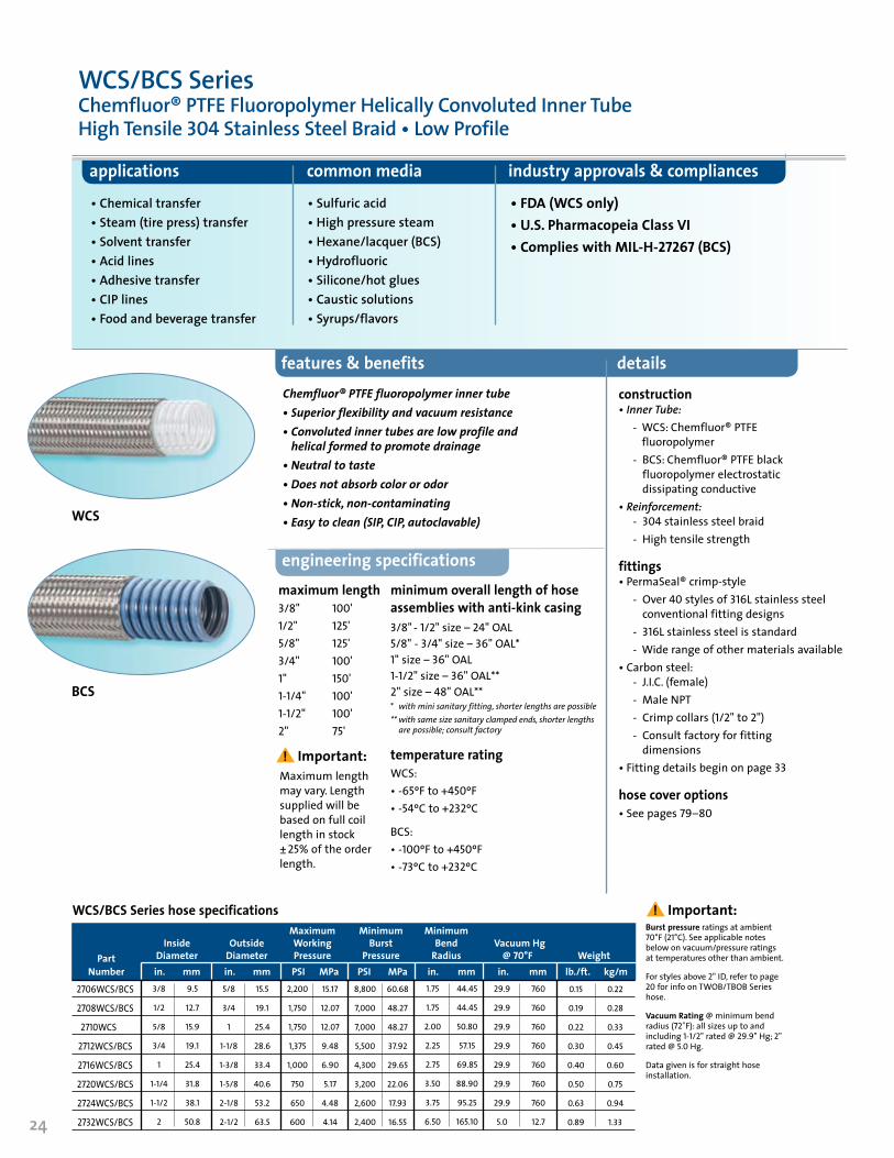
features & benefits details
applications common media industry approvals & compliances
• Chemical transfer• Steam (tire press) transfer• Solvent transfer• Acid lines• Adhesive transfer• CIP lines• Food and beverage transfer
• Sulfuric acid• High pressure steam• Hexane/lacquer (BCS)• Hydrofluoric• Silicone/hot glues• Caustic solutions• Syrups/flavors
• FDA (WCS only)• U.S. Pharmacopeia Class VI• Complies with MIL-H-27267 (BCS)
maximum length 3/8" 100'1/2" 125'5/8" 125'3/4" 100'1" 150'1-1/4" 100'1-1/2" 100'2" 75'
engineering specifications
WCS
construction • Inner Tube: - WCS: Chemfluor® PTFE
fluoropolymer - BCS: Chemfluor® PTFE black
fluoropolymer electrostatic dissipating conductive
• Reinforcement: - 304 stainless steel braid
- High tensile strength
fittings • PermaSeal® crimp-style - Over 40 styles of 316L stainless steel
conventional fitting designs - 316L stainless steel is standard - Wide range of other materials available• Carbon steel:
- J.I.C. (female) - Male NPT - Crimp collars (1/2" to 2") - Consult factory for fitting
dimensions• Fitting details begin on page 33
hose cover options• See pages79–80
Chemfluor®PTFEfluoropolymerinnertube•Superiorflexibilityandvacuumresistance•Convolutedinnertubesarelowprofileandhelicalformedtopromotedrainage
•Neutraltotaste•Doesnotabsorbcolororodor•Non-stick,non-contaminating•Easytoclean(SIP,CIP,autoclavable)
BCS
minimum overall length of hose assemblies with anti-kink casing3/8"-1/2" size – 24"OAL 5/8"- 3/4"size – 36"OAL*1"size – 36"OAL1-1/2"size – 36"OAL**2"size – 48"OAL** * with mini sanitary fitting, shorter lengths are possible** with same size sanitary clamped ends, shorter lengths
are possible; consult factory
temperature ratingWCS: • -65ºF to +450ºF • -54ºC to +232ºC
BCS: • -100ºF to +450ºF• -73ºC to +232ºC
WCS/BCS SeriesChemfluor® PTFE Fluoropolymer Helically Convoluted Inner Tube High Tensile 304 Stainless Steel Braid • Low Profile
WCS/BCS Series hose specifications Maximum Minimum Minimum Inside Outside Working Burst Bend Vacuum Hg Part Diameter Diameter Pressure Pressure Radius @ 70°F Weight Number in. mm in. mm PSI MPa PSI MPa in. mm in. mm lb./ft. kg/m
2706WCS/BCS
2708WCS/BCS
2710WCS
2712WCS/BCS
2716WCS/BCS
2720WCS/BCS
2724WCS/BCS
2732WCS/BCS
3/8
1/2
5/8
3/4
1
1-1/4
1-1/2
2
9.5
12.7
15.9
19.1
25.4
31.8
38.1
50.8
5/8
3/4
1
1-1/8
1-3/8
1-5/8
2-1/8
2-1/2
15.5
19.1
25.4
28.6
33.4
40.6
53.2
63.5
2,200
1,750
1,750
1,375
1,000
750
650
600
15.17
12.07
12.07
9.48
6.90
5.17
4.48
4.14
8,800
7,000
7,000
5,500
4,300
3,200
2,600
2,400
60.68
48.27
48.27
37.92
29.65
22.06
17.93
16.55
1.75
1.75
2.00
2.25
2.75
3.50
3.75
6.50
44.45
44.45
50.80
57.15
69.85
88.90
95.25
165.10
29.9
29.9
29.9
29.9
29.9
29.9
29.9
5.0
760
760
760
760
760
760
760
12.7
0.15
0.19
0.22
0.30
0.40
0.50
0.63
0.89
0.22
0.28
0.33
0.45
0.60
0.75
0.94
1.3324
Burst pressure ratings at ambient 70°F (21°C). See applicable notes below on vacuum/pressure ratings at temperatures other than ambient.
For styles above 2" ID, refer to page 20 for info on TWOB/TBOB Series hose.
Vacuum Rating @ minimum bend radius (72˚F): all sizes up to and including 1-1/2" rated @ 29.9" Hg; 2" rated @ 5.0 Hg.
Data given is for straight hose installation.
! Important:Maximum length may vary. Length supplied will be based on full coil length in stock ±25% of the order length.
! Important:
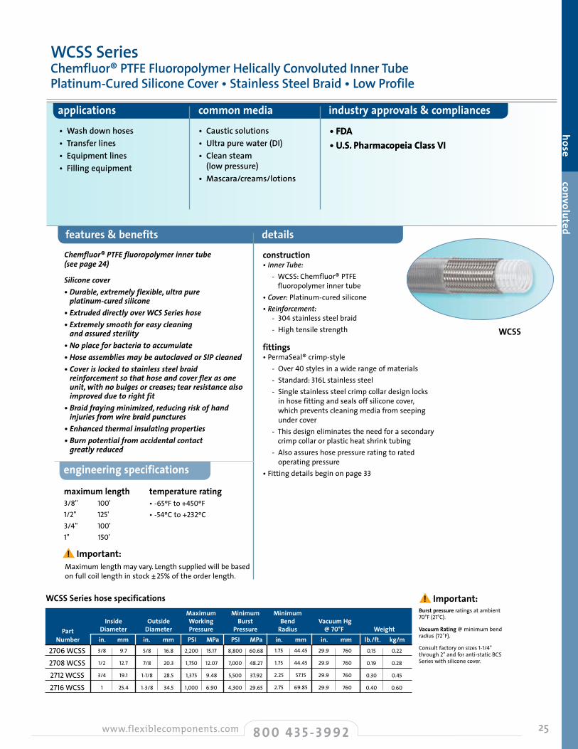
25
hose convoluted
features & benefits details
applications common media industry approvals & compliances
maximum length 3/8" 100'1/2" 125'3/4" 100'1" 150'
temperature rating• -65ºF to +450ºF • -54ºC to +232ºC
engineering specifications
• Wash down hoses• Transfer lines• Equipment lines• Filling equipment
• Caustic solutions• Ultra pure water (DI)• Clean steam (low pressure)• Mascara/creams/lotions
• FDA • U.S. Pharmacopeia Class VI• FDA • U.S. Pharmacopeia Class VI
WCSS
Chemfluor®PTFEfluoropolymerinnertube(seepage24)
Siliconecover•Durable,extremelyflexible,ultrapureplatinum-curedsilicone
•ExtrudeddirectlyoverWCSSerieshose•Extremelysmoothforeasycleaningandassuredsterility
•Noplaceforbacteriatoaccumulate•HoseassembliesmaybeautoclavedorSIPcleaned•Coverislockedtostainlesssteelbraidreinforcementsothathoseandcoverflexasoneunit,withnobulgesorcreases;tearresistancealsoimprovedduetorightfit
•Braidfrayingminimized,reducingriskofhandinjuriesfromwirebraidpunctures
•Enhancedthermalinsulatingproperties•Burnpotentialfromaccidentalcontactgreatlyreduced
construction • Inner Tube: - WCSS: Chemfluor® PTFE
fluoropolymer inner tube• Cover: Platinum-cured silicone • Reinforcement:
- 304 stainless steel braid - High tensile strength
fittings • PermaSeal® crimp-style - Over 40 styles in a wide range of materials - Standard: 316L stainless steel - Single stainless steel crimp collar design locks
in hose fitting and seals off silicone cover, which prevents cleaning media from seeping under cover
- This design eliminates the need for a secondary crimp collar or plastic heat shrink tubing
- Also assures hose pressure rating to rated operating pressure
• Fitting details begin on page 33
WCSS SeriesChemfluor® PTFE Fluoropolymer Helically Convoluted Inner Tube Platinum-Cured Silicone Cover • Stainless Steel Braid • Low Profile
Maximum Minimum Minimum Inside Outside Working Burst Bend Vacuum Hg Part Diameter Diameter Pressure Pressure Radius @ 70°F Weight Number in. mm in. mm PSI MPa PSI MPa in. mm in. mm lb./ft. kg/m
2706WCSS2708WCSS2712WCSS2716WCSS
3/8
1/2
3/4
1
9.7
12.7
19.1
25.4
5/8
7/8
1-1/8
1-3/8
16.8
20.3
28.5
34.5
2,200
1,750
1,375
1,000
15.17
12.07
9.48
6.90
8,800
7,000
5,500
4,300
60.68
48.27
37.92
29.65
1.75
1.75
2.25
2.75
44.45
44.45
57.15
69.85
29.9
29.9
29.9
29.9
760
760
760
760
WCSS Series hose specifications
0.15
0.19
0.30
0.40
0.22
0.28
0.45
0.60
Burst pressure ratings at ambient 70°F (21°C).
Vacuum Rating @ minimum bend radius (72˚F).
Consult factory on sizes 1-1/4"through 2" and for anti-static BCS Series with silicone cover.
8 0 0 4 3 5 - 3 9 9 2www.flexiblecomponents.com Convoluted
! Important:Maximum length may vary. Length supplied will be based on full coil length in stock ±25% of the order length.
! Important:

26
features & benefits details
applications common media industry approvals & compliances
• Chemical transfer• Solvent transfer• Acid lines• CIP lines• Food and beverage
• Sulfuric acid• Hexane/lacquer (BCP)• Hydrofluoric• Caustic solutions• Hot water cleaning
• USDA• FDA (WCP only)• U.S. Pharmacopeia Class VI
maximum length WCP:1/2" 100'3/4" 100'1" 100'
BCP:1/2" 100'3/4" 100'1" 100'
temperature rating• -40ºF to +250ºF• -40ºC to +121ºC
engineering specifications
Burst pressure ratings at ambient 70°F (21°C). See applicable notes below on vacuum/pressure ratings at temperatures other than ambient.Data given is for straight hose installation through 250ºF.Decrease working pressure to 30 psig for all sizes @ temperatures above 175ºF. Consult factory for higher temperature applications. Specifications shown here supercede all previous catalogs.
construction • Inner Tube: - WCP: Chemfluor® natural
PTFE fluoropolymer - BCP: Chemfluor® PTFE
fluoropolymer electrostatic dissipating conductive (black)
• Reinforcement: Polypropylene braid - Each strand of large diameter
(denier) polypropylene monofilament is twisted and subsequently twined prior to braiding
- Tested for maximum abrasion and chemical resistance
fittings PermaSeal® crimp-style• Over 40 styles of316L stainless steel con-
ventional fitting designs• Standard: 316L stainless steel• Consult factory for optional fitting
materials — carbon steel, PVDF (Kynar®), polypropylene or other alloys
• Fitting details begin on page 33
hose cover options • See pages 79-80
Chemfluor®PTFEfluoropolymerinnertube(seepage 24)
Polypropylenebraid•Ultraviolet(UV)stabilized•Lightweight•Doesnotconductinternalheatasreadilyasstainlesssteelbraidedhoses
•Burnpotentialfromaccidentalcontactgreatlyreduced
BCP
WCP
WCP/BCP SeriesChemfluor® PTFE Fluoropolymer Helically Convoluted Inner Tube Polypropylene Braid • Low Profile
Maximum Minimum Minimum Inside Outside Working Burst Bend Part Diameter Diameter Pressure Pressure Radius Vacuum Hg Weight Number in. mm in. mm PSI MPa PSI MPa in. mm in. mm lb./ft. kg/m2708WCP/BCP
2712WCP/BCP
2716WCP/BCP
1/2
3/4
1
12.7
19.1
25.4
7/8
1-1/4
1-1/2
21.3
32.8
39.6
250
250
250
1.72
1.72
1.72
1,000
1,000
1,000
6.90
6.90
6.90
1.75
2.25
2.75
44.45
57.15
69.85
29.9
25.0
22.0
760
635
559
WCP/BCP Series hose specifications
0.10
0.19
0.24
0.15
0.28
0.36
8 0 0 4 3 5 - 3 9 9 2 www.flexiblecomponents.comConvoluted
! Important:
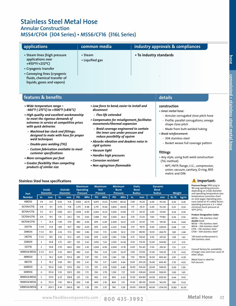
27
hose convoluted • stainless steel metal hose
applications common media industry approvals & compliances
• Steam lines (high pressure applications over +450ºF/+232ºC)
• Cryogenic transfer• Conveying lines (cryogenic
fluids, chemical transfer of liquids, gases and vapors)
• Steam• Liquified gas
• To industry standards
•Widetemperaturerange–-460°F(-273°C)to+1500°F(+816°C)
•Highqualityandexcellentworkmanshiptomeettherigorousdemandsofextremesinserviceatcompetitivepriceswithquickdeliveries
-Machinedbarstockendfittings;designedtomatewithhoseforproperweldtechniques
-Double-passwelding(TIG) -Customfabricationavailabletomeet
customerspecifications•Morecorrugationsperfoot•Greaterflexibilitythancompetingproductsofsimilarsize
•Lowforcetobend;easiertoinstallanddisconnect
-Flex-lifeextended•Compensatesformisalignment,facilitatesmovements/thermalexpansion
-Braidcoverageengineeredtocontaintheinnercoreunderpressureandreducepossibilityofsquirm
•Absorbsvibrationanddeadensnoiseinrigidsystems
•Vacuumtight•Handleshighpressures•Corrosionresistant•Non-aging/non-flammable
construction• Inner metal hose: - Annular corrugated close pitch hose - Profile: parallel corrugations, omega
shape close pitch - Made from butt-welded tubing• Braid reinforcement: - 304 stainless steel - Basket weave full coverage pattern
fittings• Any style, using butt weld construction (TIG method) - NPT, FNTP, flange, J.I.C., compression,
union, vacuum, sanitary, O-ring, BSP, metric and DIN
Pressure Range 3850 psig to 185 psig operating pressure, depending on inside diameter and operating temperature (see temperature correction chart on next page). Operating pres-sures based on 4:1 safety factor; operating pressure x4 = rated minimum burst pressure at 70ºF (21ºC).
Product Designation Codes MDS6 – 316 stainless steel double braid MSS6 – 316 stainless steel MSS4 – 304 stainless steel* CF16 – 316 stainless steel CF04 – 304 stainless steel*
*All braid reinforcement is 304 stainless steel.
Consult factory for availability of larger sizes and inner cores of other alloys.
Metal hose is rated for full vacuum.
Stainless Steel hose specifications Maximum Maximum Minimum Static Dynamic Inside Outside Operating Test Burst Bend Bend Part Diameter Diameter Pressure Pressure Pressure Radius Radius Weight Number in. mm in. mm PSI MPa PSI MPa PSI MPa in. mm in. mm lb./ft. kg/m
4MDS6
6CF04/CF16
8CF04/CF16
12CF04/CF16
16CF04/CF16
20CF16
24MSS4
24CF16
32MSS4
32CF16
40MSS4/MSS6
48MSS4
48CF16
64MSS4
64MSS6
80MSS4/MSS6
96MSS4/MSS6
128MSS4/MSS6
1/4
3/8
1/2
3/4
1
1-1/4
1-1/2
1-1/2
2
2
2-1/2
3
3
4
4
5
6
8
6.4
9.5
12.7
19.1
25.4
31.8
38.1
38.1
50.8
50.8
63.5
76.2
76.2
101.6
101.6
127.0
152.4
203.2
0.62
0.70
0.80
1.15
1.49
1.80
2.26
2.10
2.72
2.70
3.50
4.00
3.90
5.00
5.10
6.25
7.30
9.45
15.8
17.8
20.3
29.2
37.9
45.7
57.4
53.3
69.1
68.6
88.9
101.6
99.1
127.0
129.5
158.8
185.4
240.0
3,850
1,375
1,000
725
580
580
560
435
525
500
380
285
350
250
250
225
200
185
26.55
9.48
6.90
5.00
4.00
4.00
3.86
3.00
3.62
3.45
2.62
1.97
2.41
1.72
1.72
1.55
1.38
1.28
4,875
2,175
2,063
1,088
870
870
1,120
870
1,050
1,000
760
570
750
375
550
450
400
370
13,000
5,800
5,500
3,500
2,400
2,320
2,240
1,740
2,100
2,000
1,520
1,140
1,400
1,000
1,100
900
800
740
33.61
15.00
14.22
7.50
6.00
6.00
7.72
6.00
7.24
6.90
5.24
3.93
5.17
2.59
3.79
3.10
2.76
2.55
89.63
40.00
37.90
24.11
16.53
15.98
16.12
11.98
14.46
13.78
10.47
7.85
9.64
6.89
7.57
6.20
5.51
5.09
3.00
1.15
1.75
2.10
2.50
3.10
3.50
4.75
4.50
6.00
5.00
7.50
8.00
10.00
9.00
12.00
15.00
20.00
76.20
29.21
44.45
53.34
63.50
78.74
88.90
120.65
114.30
152.40
127.00
190.50
203.20
254.00
228.60
304.80
381.00
508.00
6.00
6.00
5.00
7.00
7.70
9.00
10.50
9.50
12.00
11.50
13.00
16.00
16.00
20.00
20.00
24.00
30.00
40.00
152.40
152.40
127.00
177.80
195.58
228.60
266.70
241.30
304.80
292.10
330.20
406.40
406.40
508.00
508.00
609.60
762.00
1,016.00
0.30
0.23
0.24
0.36
0.44
0.68
1.80
1.09
2.37
1.55
2.70
2.87
2.70
4.00
3.90
6.66
7.80
10.80
0.45
0.34
0.36
0.54
0.66
1.01
2.68
1.62
3.53
2.31
4.02
4.28
4.02
5.96
5.81
9.92
11.62
16.09
detailsfeatures & benefits
8 0 0 4 3 5 - 3 9 9 2www.flexiblecomponents.com Metal Hose
! Important:
Stainless Steel Metal Hose Annular Construction MSS4/CF04 (304 Series) • MSS6/CF16 (316L Series)

28
metal hose fitting options
specifying the proper metal hose temperature correction factorA number of factors should be taken into consideration when specifying 316L/304 Stainless Steel Metal Hose.
Material to be transferred• Select 316L or 304 stainless steel inner core,
depending on the type of medium.
Corrosion potential• The corrosive nature of both the medium to be
conveyed and the outside environment should be taken into account; the corrosive effects of many chemicals can be accelerated by higher temperatures.
• If the material to be transferred is gaseous, flow rates should be specified, especially if velocity is to approach or exceed 180 feet per second.
• Are the fittings to be of the same alloy material?
Inside diameter (ID) of hose
Relationship of pressure rating, temperature and type of service• Operating pressures listed in the accompanying
specifications chart on page 27 reflect a rating based on one braid reinforcement and a minimum safety ratio of 4:1, burst pressure to rated operation pressure.
• Ratings are based on operating at ambient temperature — 70ºF (21ºC). If your application exceeds this temperature, consult the accompanying temperature correction chart to calculate the adjusted pressure rating at your particular operation temperature.
Maximum service temperature• 316L stainless steel: +1500ºF (+815ºC)• 304 stainless steel: +850ºF (+454ºC)
As the service temperature increases, the maximum pressure a hose assembly can withstand decreases. Use the factors given in the accompanying chart to approximate the safe working pressure at elevated temperatures; this figure will enable you to determine the optimum assembly for your application.
ExampleIs 1" 304 Stainless Steel Metal Hose (product designation CF04) suitable for 200 PSI @ 700ºF?
Given:• Maximum operating temperature:
700ºF• Maximum operating pressure:
200 PSIG• Computations: - Check specifications chart
for minimum rated burst pressure for 1" CF04 = 2400
- Check temperature correction factors chart for correction factor for 1" CF04 at 700ºF = .70
- Rated burst pressure: 2400 x .70 = 1680 PSIG (rated burst pressure at 700ºF)
- Safe operating pressure: 1680/4 = 420 PSIG (using 4:1 safety factor)
• Result - 1" CF04 is rated at 420 PSIG MAWP,
well in excess of the 200 PSI of the example operating environment.
J.I.C. Female Swivel Style 02
Machined 37°and 45° seat withJ.I.C. swivel nut
Female NPT Style 06Pipe thread–hex style supplied
standard through 1"Style 05
Female NPT round with wrench flats
Flange Retainer, Lap-Joint Style Style 12Lap-joint forged flange per ASTM specifications
Schedule 10 Type “C” stub ends & 150# epoxy coated carbon steel lap-joint flanges standard.
Consult factory for optional stainless steel flanges and alternative stub end types/schedules
Male NPTStyle 03
Pipe thread–with integral hex
J.I.C. Adapter Union Male Style 08 Style 07
Consult factory for female adapter union
Female Cam and Groove (Swivel) Style 16316 stainless steel with or
without locking arms
Plain Pipe End /Tube End Style 01/Style 41
Style 01 Pipe end (Sch 40) or
heavy weight (Sch 80)Style 41
Plain end specified by O.D. and wall thickness
Male Pipe, Plain Style 04
Pipe thread–Sch 40 standard weight
Sanitary Clamp Style 10/Style 11316L mini (11) or full size clamp
style (10). 45° and 90° elbow also available
Male Cam and GrooveStyle 17 316 SS
Many different types of fittings can be attached to metal hose. Flexible Components stainless steel fittings are typically fully machined from bar stock and are engineered for a tight fit that allows for proper weld penetration and long service life. Some of the more popular fitting styles are shown below. However, due to the versatility of the welded hose construction, many types of fittings can be welded to meet your needs; consult the factory for availability and fitting dimensions. (More information on the following fittings can be found starting on page 33.)
TemperatureCorrection Factors
Temp. Temp. Correction °F Number
70 1.00 150 .97 200 .94 250 .92 300 .88 350 .86 400 .84 450 .82 500 .80 600 .75 700 .70 800 .66 900 .62 1000 .60 1100 .58 1200 .55 1300 .50 1400 .44 1500 .40
Stainless Steel Metal Hose • Annular Construction (continued)
8 0 0 4 3 5 - 3 9 9 2 www.flexiblecomponents.comMetal Hose
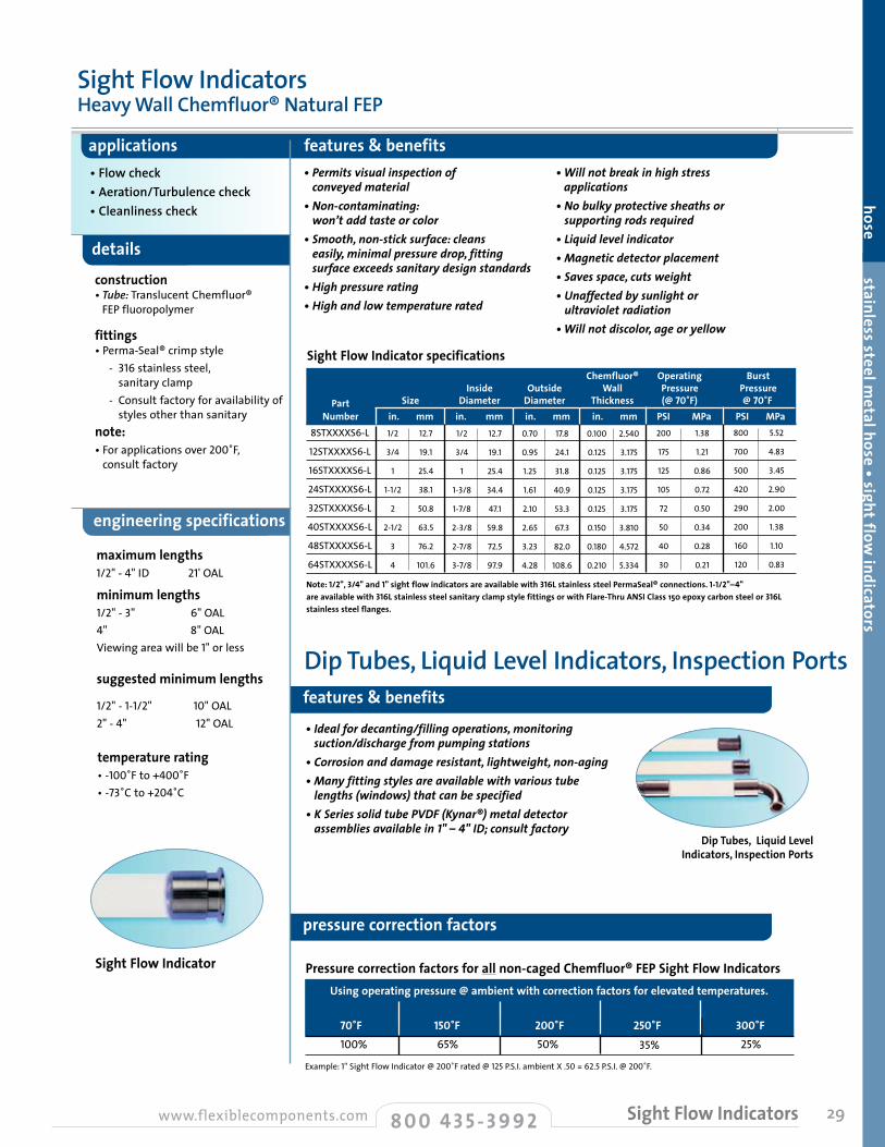
29
hose stainless steel metal hose • sight flow
indicators
•Idealfordecanting/fillingoperations,monitoringsuction/dischargefrompumpingstations
•Corrosionanddamageresistant,lightweight,non-aging•Manyfittingstylesareavailablewithvarioustubelengths(windows)thatcanbespecified
•KSeriessolidtubePVDF(Kynar®)metaldetectorassembliesavailablein1" – 4"ID;consultfactory
applications features & benefits• Flow check• Aeration/Turbulence check• Cleanliness check
maximum lengths 1/2" - 4" ID 21'OAL
temperature rating•-100˚F to +400˚F• -73˚C to +204˚C
•Permitsvisualinspectionofconveyedmaterial
•Non-contaminating:won’taddtasteorcolor
•Smooth,non-sticksurface:cleanseasily,minimalpressuredrop,fittingsurfaceexceedssanitarydesignstandards
•Highpressurerating•Highandlowtemperaturerated
•Willnotbreakinhighstressapplications
•Nobulkyprotectivesheathsorsupportingrodsrequired
•Liquidlevelindicator•Magneticdetectorplacement•Savesspace,cutsweight•Unaffectedbysunlightorultravioletradiation
•Willnotdiscolor,ageoryellow
Sight Flow Indicator specifications Chemfluor® Operating Burst Inside Outside Wall Pressure Pressure Part Size Diameter Diameter Thickness (@ 70˚F) @ 70˚F Number in. mm in. mm in. mm in. mm PSI MPa PSI MPa
Note: 1/2", 3/4" and 1" sight flow indicators are available with 316L stainless steel PermaSeal® connections. 1-1/2"–4" are available with 316L stainless steel sanitary clamp style fittings or with Flare-Thru ANSI Class 150 epoxy carbon steel or 316L stainless steel flanges.
8STXXXXS6-L
12STXXXXS6-L
16STXXXXS6-L
24STXXXXS6-L
32STXXXXS6-L
40STXXXXS6-L
48STXXXXS6-L
64STXXXXS6-L
1/2
3/4
1
1-1/2
2
2-1/2
3
4
12.7
19.1
25.4
38.1
50.8
63.5
76.2
101.6
1/2
3/4
1
1-3/8
1-7/8
2-3/8
2-7/8
3-7/8
12.7
19.1
25.4
34.4
47.1
59.8
72.5
97.9
0.70
0.95
1.25
1.61
2.10
2.65
3.23
4.28
17.8
24.1
31.8
40.9
53.3
67.3
82.0
108.6
0.100
0.125
0.125
0.125
0.125
0.150
0.180
0.210
2.540
3.175
3.175
3.175
3.175
3.810
4.572
5.334
200
175
125
105
72
50
40
30
1.38
1.21
0.86
0.72
0.50
0.34
0.28
0.21
800
700
500
420
290
200
160
120
5.52
4.83
3.45
2.90
2.00
1.38
1.10
0.83
Using operating pressure @ ambient with correction factors for elevated temperatures. 70˚F 150˚F 200˚F 250˚F 300˚F
Example: 1" Sight Flow Indicator @ 200˚F rated @ 125 P.S.I. ambient X .50 = 62.5 P.S.I. @ 200˚F.
100%
Pressure correction factors for all non-caged Chemfluor® FEP Sight Flow Indicators
65% 50% 35% 25%
construction • Tube: Translucent Chemfluor®
FEP fluoropolymer
fittings • Perma-Seal® crimp style - 316 stainless steel,
sanitary clamp - Consult factory for availability of
styles other than sanitarynote: • For applications over 200˚F,
consult factory
details
engineering specifications
Dip Tubes, Liquid Level Indicators, Inspection Portsfeatures & benefits
minimum lengths1/2" - 3" 6" OAL4" 8" OALViewing area will be 1" or less
suggested minimum lengths
1/2" - 1-1/2" 10" OAL2" - 4" 12" OAL
pressure correction factors
Sight Flow IndicatorsHeavy Wall Chemfluor® Natural FEP
8 0 0 4 3 5 - 3 9 9 2www.flexiblecomponents.com Sight Flow Indicators
Sight Flow Indicator
Dip Tubes, Liquid Level Indicators, Inspection Ports
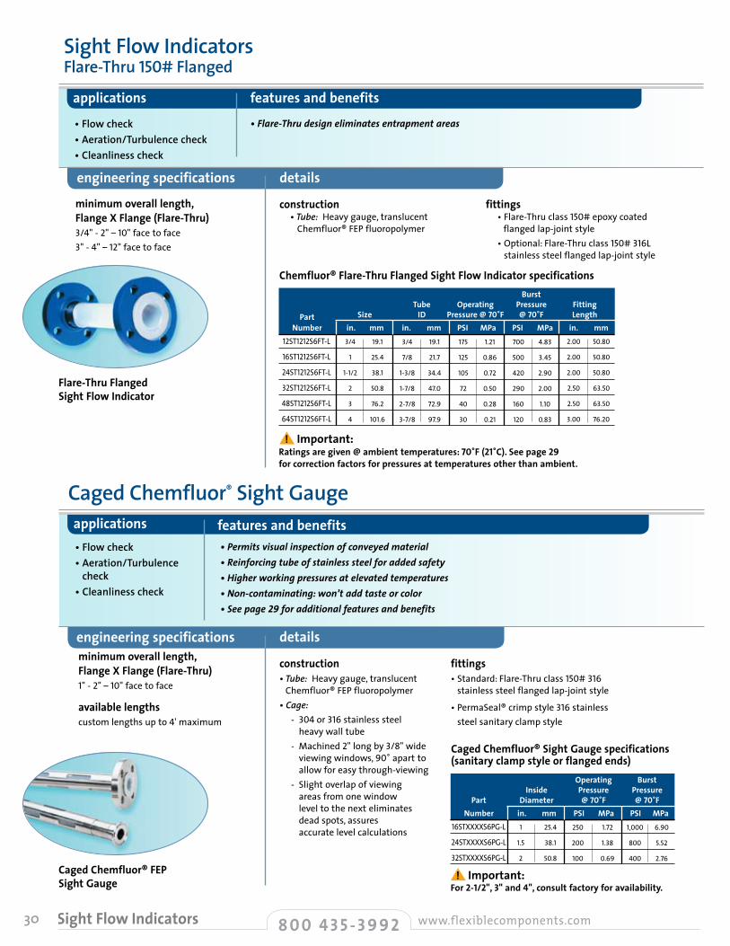
30
engineering specifications details
applications features and benefits
minimum overall length,Flange X Flange (Flare-Thru)3/4"-2"–10" face to face3"-4"–12" face to face
construction • Tube: Heavy gauge, translucent Chemfluor® FEP fluoropolymer
fittings • Flare-Thru class 150# epoxy coated flanged lap-joint style
• Optional: Flare-Thru class 150# 316L stainless steel flanged lap-joint style
• Flow check• Aeration/Turbulence check• Cleanliness check
•Flare-Thrudesigneliminatesentrapmentareas
details
applications features and benefits
minimum overall length,Flange X Flange (Flare-Thru)1"-2"–10" face to face
construction• Tube: Heavy gauge, translucent
Chemfluor® FEP fluoropolymer• Cage: - 304 or 316 stainless steel
heavy wall tube - Machined 2" long by 3/8" wide
viewing windows, 90˚ apart to allow for easy through-viewing
- Slight overlap of viewing areas from one window level to the next eliminates dead spots, assures accurate level calculations
fittings• Standard: Flare-Thru class 150# 316
stainless steel flanged lap-joint style
• PermaSeal® crimp style 316 stainless steel sanitary clamp style
• Flow check• Aeration/Turbulence
check• Cleanliness check
•Permitsvisualinspectionofconveyedmaterial•Reinforcingtubeofstainlesssteelforaddedsafety•Higherworkingpressuresatelevatedtemperatures•Non-contaminating:won’taddtasteorcolor•Seepage29foradditionalfeaturesandbenefits
Flare-Thru Flanged Sight Flow Indicator
Caged Chemfluor® FEP Sight Gauge
Burst Tube Operating Pressure Fitting Part Size ID Pressure @ 70˚F @ 70˚F Length Number in. mm in. mm PSI MPa PSI MPa in. mm
Ratings are given @ ambient temperatures: 70˚F (21˚C). See page 29 for correction factors for pressures at temperatures other than ambient.
12ST1212S6FT-L
16ST1212S6FT-L
24ST1212S6FT-L
32ST1212S6FT-L
48ST1212S6FT-L
64ST1212S6FT-L
3/4
1
1-1/2
2
3
4
19.1
25.4
38.1
50.8
76.2
101.6
3/4
7/8
1-3/8
1-7/8
2-7/8
3-7/8
19.1
21.7
34.4
47.0
72.9
97.9
175
125
105
72
40
30
1.21
0.86
0.72
0.50
0.28
0.21
700
500
420
290
160
120
4.83
3.45
2.90
2.00
1.10
0.83
2.00
2.00
2.00
2.50
2.50
3.00
50.80
50.80
50.80
63.50
63.50
76.20
Chemfluor® Flare-Thru Flanged Sight Flow Indicator specifications
Caged Chemfluor® Sight Gauge
available lengthscustom lengths up to 4'maximum
engineering specifications
Operating Burst Inside Pressure Pressure Part Diameter @ 70˚F @ 70˚F Number in. mm PSI MPa PSI MPa
For 2-1/2", 3" and 4", consult factory for availability.
16STXXXXS6PG-L
24STXXXXS6PG-L
32STXXXXS6PG-L
1
1.5
2
25.4
38.1
50.8
250
200
100
1.72
1.38
0.69
1,000
800
400
6.90
5.52
2.76
Caged Chemfluor® Sight Gauge specifications (sanitary clamp style or flanged ends)
8 0 0 4 3 5 - 3 9 9 2 www.flexiblecomponents.comSight Flow Indicators
Sight Flow Indicators Flare-Thru 150# Flanged
! Important:
! Important:

31
hose sight flow indicators • chlorine transfer hose
features & benefits details
applications common media industry approvals & compliances
temperature rating • -40˚F to +120˚F
• -40˚C to +49˚C
construction • Inner Tube: One-piece extruded
Chemfluor® PTFE fluoropolymer - No seams or voids
• Cover: Thick-strand chafe-resistant PVDF (Kynar®) - Protects against abrasion
• Reinforcement: Two high tensile strength PVDF (Kynar®) braids - For high pressure rating
fittings• Standard: Schedule 80 Monel® stub end 300# epoxy coated carbon steel lap-joint flange
• Schedule 80 Monel® hex male NPT (1" wide wrenching flats)
- Schedule 80 Monel® R405 male NPT or Schedule 80 stub end available
• Internal Monel® crimp ferrule locks fitting to inner tube and two reinforcement braids
• Special PVDF (Kynar®) fittings available• Special Hastelloy® fittings for wet
chlorine applications
engineering specifications
• Tank car loading/unloading• Pulp and paper bleaching• Chemical transfer
• Chlorine• Bromine• Sodium hydroxide• Sodium hypochlorite• Sulfuric and hydrochloric acids• Other corrosive materials
• Manufactured in accordance with Chlorine Institute Pamphlet 6 piping specifications
CL
Quality Control and Testing• Each hose is material lot traceable• Each hose is subject to stringent
QC procedures throughout the manufacturing process
• Each hose is permanently identified in accordance with Chlorine Institute specifications
• Each hose is thoroughly cleaned before assembly; no oils, solvents or other contaminants are used in the assembly process
• Each hose is pressure tested with nitrogen gas at twice the rated operating pressure while fully submerged under water
• Each hose is dried and capped for shipment
• A unique serial number is applied to each end of the hose for further traceability; permanent log of all hose assemblies maintained at factory
• Unexcelledchemicalresistanceforlongerservicelife• Notsubjecttostresscorrosion,pinholingorflexcracking
• Convolutedinnertubeislowprofileandhelical formedtopromoteself-drainage• Moisturewillnotaffectinnertube• Doesnotneedtobecleanedandcappedaftereveryuse
• Minimumpressuredropforfasterloadingandunloading
• Lightweightandultraflexibleforhandlingease• Lowforcetobend• Canbeinspectedsafely• LesscostlythanMonel®(metal)hose• Widehexflatsforeasywrenching
CL Series Chlorine Transfer Hose AssembliesChemfluor® PTFE Fluoropolymer Helically Convoluted Inner Tube PVDF (Kynar®) Braids
Maximum Minimum Minimum Inside Outside Working Burst Bend Part Diameter Diameter Pressure Pressure Radius Number in. mm in. mm PSI MPa PSI MPa in. mm
XXXX indicate fitting styles. See page 100for fitting style indicators and assembly part number details.
8CLXXXXMKY
16CLXXXXMKY
24CLXXXXMKY
1/2
1
1-1/2
12.7
25.4
38.1
1
1-5/8
2-1/8
26.0
41.9
54.0
500
375
375
3.45
2.59
2.59
2,500
1,875
1,875
17.24
12.93
12.93
2.50
8.00
10.00
63.50
203.20
254.00
CL Series hose specificationsBurst pressure ratings at ambient 70°F (21°C). Important note regarding part numbers: The X’s shown in part numbers at left are replaced with 03 (NPT) and/or 12 (Flange Lap Joint Style), depending on the type of fitting specified for the assembly. For example, the part number for a 1/2" assembly featuring NPT fittings at both ends would be 8CL0303MKY. The part number for a 1" assembly with an NPT fitting at one end and a flange fitting at the other would be 16CL0312MKY. When both fittings are flange, add a second “M” to the part number; in this case, the part number for a 1-1/2" assembly would be 24CL1212MMKY.Choose flange material: C3 = 300lbs. carbon steel 300#; 43=304 stainless steel 300#; 63 = 316 stainless steel 300#. See page 100 for ordering information.These hoses are not metrically sized; metric dimensions provided as a convenience only.Test Pressure = 2x maximum operating pressure.
StainlesssteelcrimpringsecuresPVDF(Kynar®)abrasioncover.ApermanentstainlesssteelIDbandprovidesthefollowinginformation:•“FlexibleComponents”•“ForChlorineService”•Dateofmanufacture•Maximumallowableworkingpressure
•Usabletemperaturerange•Minimumbendradius•Testpressure
8 0 0 4 3 5 - 3 9 9 2www.flexiblecomponents.com Chlorine Transfer Hose
! Important:
! Important:
maximum length 1/2" 30'OAL1" 50'OAL1-1/2" 30'OAL

32
description
applications features & benefits
• Hot glues• Filling machines• Food casings• Food processing machines• Food lines• Hot waxes• Pharmaceutical• Cosmetics• Outdoor applications where temperature
must be maintained
• Available on a “built to order” basis on virtually all hose assemblies manufactured by Flexible Components
• Electrically heated trace feature, designed to maintain internal temperature of conveyed materials regardless of hose installation
• Up to a maximum temperature of +250ºF/+121ºC
•CanbeusedwithflexiblestainlesssteelbraidedTS/WCS/TWOBSerieshoseassemblies
-ConsultfactoryforavailabilityofEHHoptionwithotherFlexibleComponentshoseassemblies
•Smalloutsidediametereliminatesbulkyhose•Externaltemperaturecontrolleravailable•Customfabricationavailable•Varietyofendfittingsavailable•HoseconstructionmaterialsFDAapproved
Electrically Heated Hose • EHH Series
construction• Externally controlled heaters• 115VAC or 220VAC• J or K thermocouples available• RTD available• A wide variety of external protection
available - Silicone - FEP heat shrink - Silicone/fiberglass firesleeve - Stainless steel anti-kink casing - Polypropylene braided - PVDF braided chafe guards
Consult factory for details on how to order. For a complete six-page catalog on EHH Series products, call customer service and ask for literature #FLS-3028.
details
8 0 0 4 3 5 - 3 9 9 2 www.flexiblecomponents.comElectrically Heated Hose
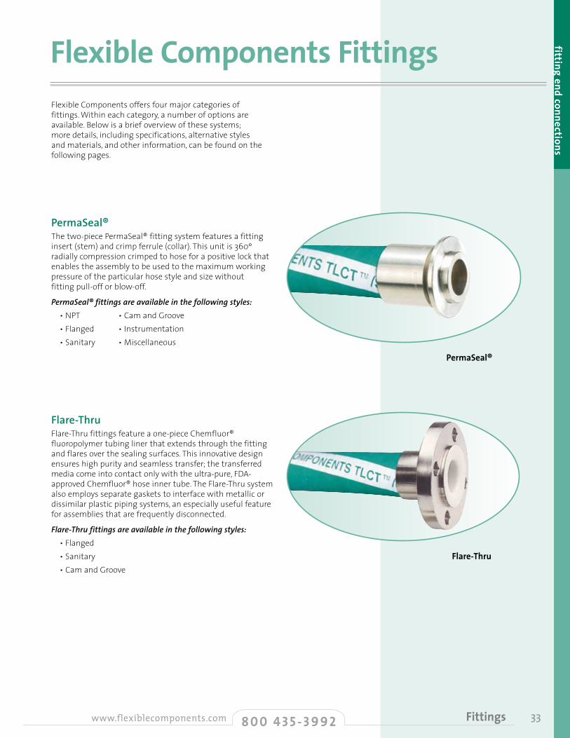
fitting end connections
Flexible Components FittingsFlexible Components offers four major categories of fittings. Within each category, a number of options are available. Below is a brief overview of these systems; more details, including specifications, alternative styles and materials, and other information, can be found on the following pages.
338 0 0 4 3 5 - 3 9 9 2www.flexiblecomponents.com Fittings
Flare-Thru
PermaSeal®The two-piece PermaSeal® fitting system features a fitting insert (stem) and crimp ferrule (collar). This unit is 360º radially compression crimped to hose for a positive lock that enables the assembly to be used to the maximum working pressure of the particular hose style and size without fitting pull-off or blow-off.
PermaSeal® fittings are available in the following styles:• NPT • Cam and Groove• Flanged • Instrumentation• Sanitary • Miscellaneous
Flare-ThruFlare-Thru fittings feature a one-piece Chemfluor® fluoropolymer tubing liner that extends through the fitting and flares over the sealing surfaces. This innovative design ensures high purity and seamless transfer; the transferred media come into contact only with the ultra-pure, FDA-approved Chemfluor® hose inner tube. The Flare-Thru system also employs separate gaskets to interface with metallic or dissimilar plastic piping systems, an especially useful feature for assemblies that are frequently disconnected.
Flare-Thru fittings are available in the following styles:• Flanged• Sanitary• Cam and Groove
PermaSeal®
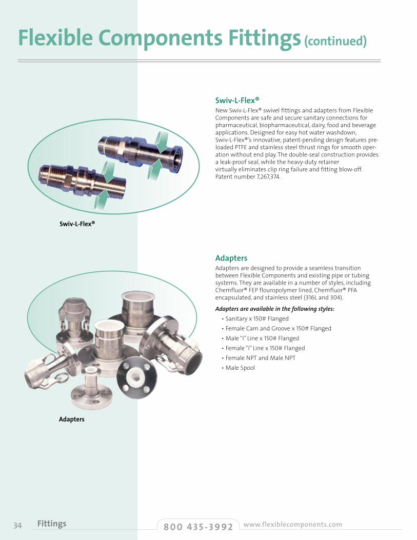
8 0 0 4 3 5 - 3 9 9 2 www.flexiblecomponents.comFittings34
Flexible Components Fittings (continued)
Swiv-L-Flex®New Swiv-L-Flex® swivel fittings and adapters from Flexible Components are safe and secure sanitary connections for pharmaceutical, biopharmaceutical, dairy, food and beverage applications. Designed for easy hot water washdown, Swiv-L-Flex®’s innovative, patent-pending design features pre-loaded PTFE and stainless steel thrust rings for smooth oper-ation without end play. The double-seal construction provides a leak-proof seal, while the heavy-duty retainer virtually eliminates clip ring failure and fitting blow-off. Patent number 7,267,374.
AdaptersAdapters are designed to provide a seamless transition between Flexible Components and existing pipe or tubing systems. They are available in a number of styles, including Chemfluor® FEP flouropolymer lined, Chemfluor® PFA encapsulated, and stainless steel (316L and 304).
Adapters are available in the following styles:• Sanitary x 150# Flanged• Female Cam and Groove x 150# Flanged• Male “I” Line x 150# Flanged• Female “I” Line x 150# Flanged• Female NPT and Male NPT• Male Spool
Swiv-L-Flex®
Adapters
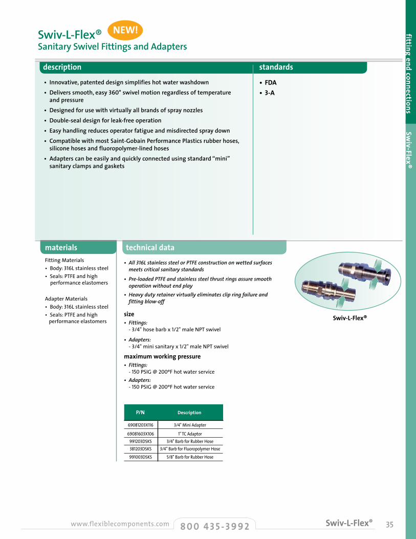
technical data
• All 316L stainless steel or PTFE construction on wetted surfaces meets critical sanitary standards
• Pre-loaded PTFE and stainless steel thrust rings assure smooth operation without end play• Heavy duty retainer virtually eliminates clip ring failure and fitting blow-off
size• Fittings: - 3/4" hose barb x 1/2" male NPT swivel
• Adapters: - 3/4" mini sanitary x 1/2" male NPT swivel
maximum working pressure• Fittings: - 150 PSIG @ 200ºF hot water service• Adapters: - 150 PSIG @ 200ºF hot water service
description standards
• Innovative, patented design simplifies hot water washdown• Delivers smooth, easy 360° swivel motion regardless of temperature and pressure• Designed for use with virtually all brands of spray nozzles• Double-seal design for leak-free operation• Easy handling reduces operator fatigue and misdirected spray down• Compatible with most Saint-Gobain Performance Plastics rubber hoses, silicone hoses and fluoropolymer-lined hoses• Adapters can be easily and quickly connected using standard “mini” sanitary clamps and gaskets
• FDA• 3-A
materialsFitting Materials• Body: 316L stainless steel• Seals: PTFE and high performance elastomers
Adapter Materials• Body: 316L stainless steel• Seals: PTFE and high performance elastomers
Swiv-L-Flex®Sanitary Swivel Fittings and Adapters
fitting end connections Swiv-Flex®
358 0 0 4 3 5 - 3 9 9 2www.flexiblecomponents.com Swiv-L-Flex®
Swiv-L-Flex®
P/N Description
69081203X116
69081603X106991203DSKS381203DSKS
991003DSKS
3/4" Mini Adapter
1"TCAdaptor3/4"Barb for Rubber Hose
3/4"Barb for Fluoropolymer Hose
5/8"Barb for Rubber Hose
NEW!
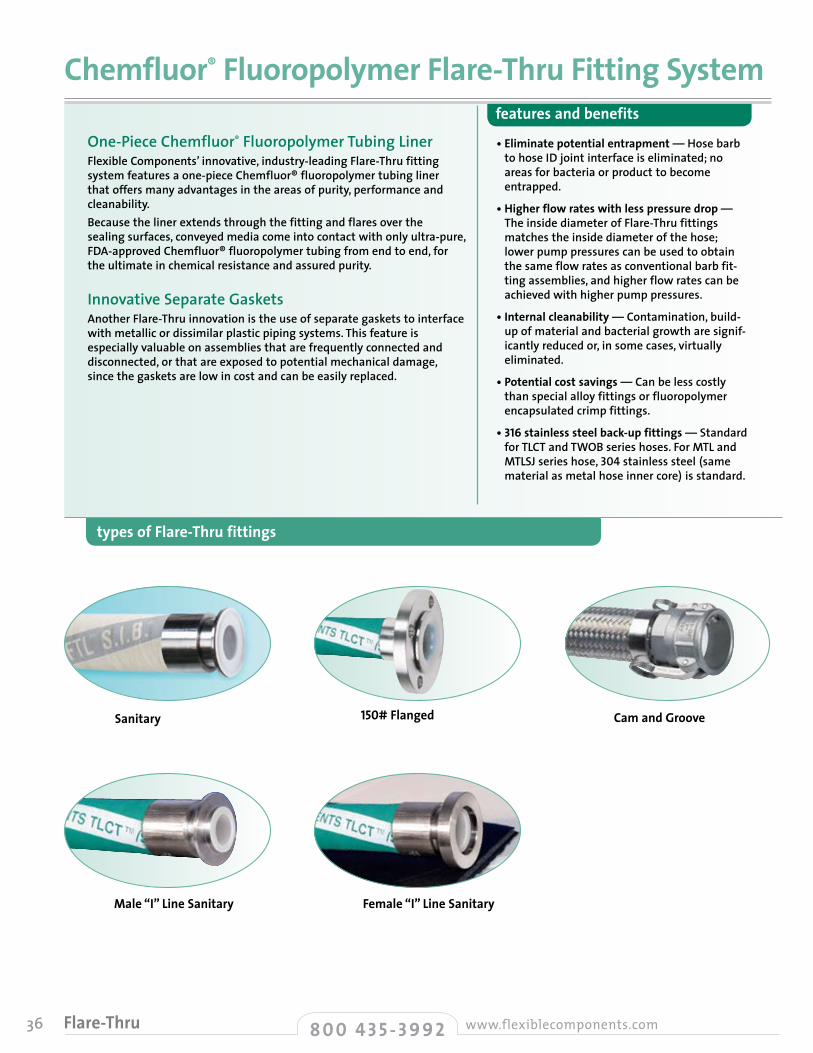
36 8 0 0 4 3 5 - 3 9 9 2 www.flexiblecomponents.comFlare-Thru
types of Flare-Thru fittings
One-Piece Chemfluor® Fluoropolymer Tubing LinerFlexible Components’ innovative, industry-leading Flare-Thru fitting system features a one-piece Chemfluor® fluoropolymer tubing liner that offers many advantages in the areas of purity, performance and cleanability. Because the liner extends through the fitting and flares over the sealing surfaces, conveyed media come into contact with only ultra-pure, FDA-approved Chemfluor® fluoropolymer tubing from end to end, for the ultimate in chemical resistance and assured purity.
Innovative Separate GasketsAnother Flare-Thru innovation is the use of separate gaskets to interface with metallic or dissimilar plastic piping systems. This feature is especially valuable on assemblies that are frequently connected and disconnected, or that are exposed to potential mechanical damage, since the gaskets are low in cost and can be easily replaced.
• Eliminate potential entrapment — Hose barb to hose ID joint interface is eliminated; no areas for bacteria or product to become entrapped.
• Higher flow rates with less pressure drop — The inside diameter of Flare-Thru fittings matches the inside diameter of the hose; lower pump pressures can be used to obtain the same flow rates as conventional barb fit-ting assemblies, and higher flow rates can be achieved with higher pump pressures.
• Internal cleanability — Contamination, build-up of material and bacterial growth are signif-icantly reduced or, in some cases, virtually eliminated.
• Potential cost savings — Can be less costly than special alloy fittings or fluoropolymer encapsulated crimp fittings.
• 316 stainless steel back-up fittings — Standard for TLCT and TWOB series hoses. For MTL and MTLSJ series hose, 304 stainless steel (same material as metal hose inner core) is standard.
Chemfluor® Fluoropolymer Flare-Thru Fitting Systemfeatures and benefits
Sanitary 150# Flanged
Male “I” Line Sanitary Female “I” Line Sanitary
Cam and Groove

37
fitting end connections Flare-Thrutechnical data
• Material conveyed touches only Chemfluor® PTFE solid gasket• Smooth Chemfluor® fluoropolymer interior surface• Promotes self-draining of entire hose assembly
temperature/pressure ratings• Pressure and temperature ratings of Flexible Components’
sanitary assemblies are dependent on clamp pressure ratings and gasket material temperature ratings
• Clamps: - Standard weight style: 150 PSIG @ 70ºF (21ºC);
125 PSIG @ 250ºF (121ºC) - Heavyweight style: 500 PSIG @ 70ºF (21ºC);
125 PSIG @ 250ºF (121ºC) - High pressure bolt style: 1500 PSIG @ 70ºF (21ºC);
125 PSIG @ 250ºF (121ºC)
• Gaskets: - Above 250ºF (121ºC), solid PTFE gaskets are required.
description standards
• Hose inner core of Chemfluor® fluoropolymer extends through stainless steel fitting and flares behind sealing gasket
• No joint between hose and fitting, no material entrapment• Temperature rated to exceed hose maximum temperature
• To industry standards• Gasket face dimensions
are standard to industry specifications
materials• 316L stainless steel
Flare-Thru FittingsSanitary Clamp Style • Style 10FT
Sanitary A I D Tube Outside Overall Inner Dia. Fitting Outer Diameter Length at Gasket Diameter
in. mm in. mm in. mm in. mm
W.S.I.B. Series hose is not vacuum rated material.
1.82
1.84
2.10
2.90
46.23
46.74
53.34
73.66
0.87
1.36
1.86
2.87
22.10
34.54
47.14
72.90
1.98
1.98
2.52
3.58
50.39
50.39
63.91
90.93
1.00
1.50
2.00
3.00
25.40
38.10
50.80
76.20
For W.S.I.B Series hose • Style 10FT
Sanitary A I D Tube Outside Overall Inner Dia. Fitting Outer Diameter Length at Gasket Diameter
in. mm in. mm in. mm in. mm2.50
3.30
4.30
63.50
83.82
109.22
0.86
1.40
1.86
22.10
35.56
47.14
1.98
1.98
2.52
50.39
50.39
63.91
1.00
1.50
2.00
25.40
38.10
50.80
For MTL Series hose • Style 10FT
! Important: All dimensions on this page are for components of Flare-Thru specification purpose only. Not sold as individual part.
8 0 0 4 3 5 - 3 9 9 2www.flexiblecomponents.com Flare-Thru • Sanitary
A I D Inside Overall Inner Dia. Fitting Outer Diameter Length at Gasket Diameter
in. mm in. mm in. mm in. mm1.88
1.90
2.16
2.63
47.75
48.26
54.86
66.80
0.87
1.36
1.86
2.86
22.10
34.54
47.14
72.54
1.98
1.98
2.52
3.58
50.39
50.39
63.91
90.93
1.00
1.50
2.00
3.00
25.40
38.10
50.80
76.20
For TWOB/TBOB, TWOY/TBOY, TWOK/TBOK, and TWOP/TBOP Series hose • Style 10FT
! Important:
Sanitary A I D Tube Outside Overall Inner Dia. Fitting Outer Diameter Length at Gasket Diameter
in. mm in. mm in. mm in. mm1.88 47.75 0.87 22.10 1.98 50.391.00 25.40
For FlexPro® Series hose • Style 10FT
Style 10FT
A
D I

38 8 0 0 4 3 5 - 3 9 9 2 www.flexiblecomponents.comFlare-Thru • Flanged
• Carbon steel• 304 stainless steel• 316 stainless steel
alternative styles
! Important: All dimensions on this page are for components of Flare-Thru specification purpose only. Not sold as individual part.
For TWOB/TBOB, TWOY/TBOY, TWOK/TBOK, TWOP/TBOP Series hose • Style 12FT A D I F Inside Overall Flare Inner Flange Outer Diameter Length Diameter Diameter Dia. Class 150 in. mm in. mm in. mm in. mm in. mm
2.40
2.40
2.50
2.50
2.50
2.70
3.50
4.00
60.96
60.96
63.50
63.50
63.50
68.58
88.90
101.60
1.68
1.68
2.00
2.50
2.88
3.62
4.12
5.00
42.67
42.67
50.80
63.50
73.15
91.95
104.65
127.00
0.75
0.75
1.00
1.25
1.50
2.00
2.38
2.95
19.05
19.05
25.40
31.75
38.10
50.80
60.45
74.93
3.50
3.88
4.25
4.63
5.00
6.00
7.00
7.50
88.90
98.43
107.95
117.48
127.00
152.40
177.80
190.50
0.50*
0.75
1.00
1.25
1.50
2.00
2.50
3.00
12.70
19.05
25.40
31.75
38.10
50.80
63.50
76.20
For PharmaSmoothTM, TLCT, WTLCT and SFTL Series hose • Style 12FT A D I F Inside Overall Flare Inner Flange Outer Diameter Length Diameter Diameter Dia. Class 150
in. mm in. mm in. mm in. mm in. mm
*Uses 3/4" TLCT hose with modified class 150 1/2" flange.
2.20
2.20
2.44
2.67
3.50
55.88
55.88
61.98
67.82
88.90
1.68
1.68
2.00
2.87
3.62
42.67
42.67
50.80
72.90
91.95
0.75
0.75
1.00
1.50
2.00
19.05
19.05
25.40
38.10
50.80
3.50
3.88
4.25
5.00
6.00
88.90
98.43
107.95
127.00
152.40
0.50*
0.75
1.00
1.50
2.00
12.70
19.05
25.40
38.10
50.80
For MTL Series hose • Style 12FT A D I F Inside Overall Flare Inner Flange Outer Diameter Length Diameter Diameter Dia. Class 150
in. mm in. mm in. mm in. mm in. mm
Note: Please check with factory for MTLSJ dimensions.
3.00
3.00
3.50
3.50
4.00
4.50
5.00
76.20
76.20
88.90
88.90
101.60
114.30
127.00
2.00
2.87
3.62
5.00
6.19
8.50
10.62
50.80
72.90
91.95
127.00
157.15
215.90
269.75
0.86
1.40
1.80
2.80
3.80
5.80
7.80
21.84
35.56
45.72
71.12
96.52
147.32
198.12
4.25
5.00
6.00
7.50
9.00
11.00
13.50
107.95
127.00
152.40
190.50
228.60
279.40
342.90
1.00
1.50
2.00
3.00
4.00
6.00
8.00
25.40
38.10
50.80
76.20
101.60
152.40
203.20
I
technical data
• Ultra pure Chemfluor® fluoropolymer liner assures cleanliness
• Full size ID through the fitting for better flow rates; maximum flow assured
• Smooth internal surface minimizes flow turbulence
• No fitting insertion to entrap material
• Maximum corrosion resistance is assured
standards
• ANSI B16.5, Class 150# and 300# ratings
• DIN P/N 16 and its equal BS4504 table 16
• BS 10 table E• J.I.S. 10 K flanges
Flare-Thru Fittings150# Flanged • Style 12FT
materials• Support stub end, crimp ring: 304or316L stainless steel• ANSI flanges available in 316L stainless steel or epoxy coated
carbon steel• 304 stainless steel, PVDF (Kynar®) or
polypropylene available special order• DIN or BS specification flanges available316 or 304 stainless
steel or zinc plated mild steel
description standards
• Swivel flange fitting design with integral Chemfluor® fluoropolymer liner and flared-over sealing surface
- Internal 316 stainless steel stub end mechanically supports liner
Style 12FT
A
D
F
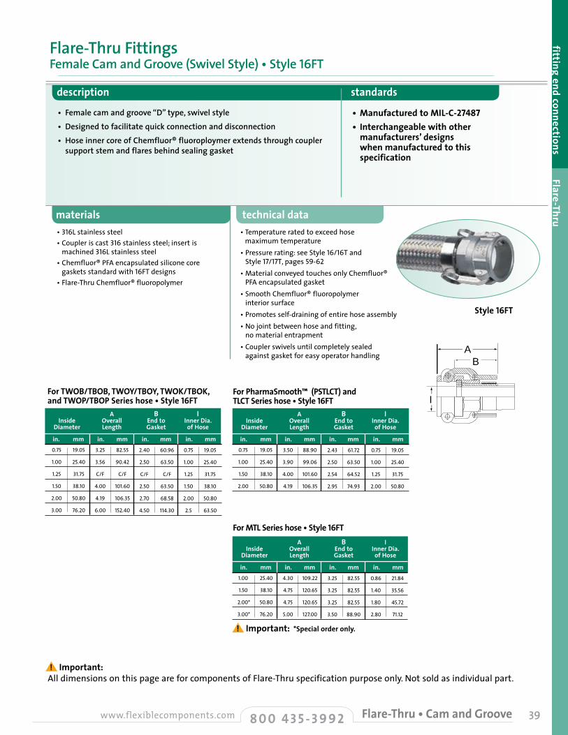
materials• 316L stainless steel • Coupler is cast 316 stainless steel; insert is
machined 316L stainless steel• Chemfluor® PFA encapsulated silicone core
gaskets standard with 16FT designs• Flare-Thru Chemfluor® fluoropolymer
technical data• Temperature rated to exceed hose
maximum temperature• Pressure rating: see Style 16/16T and
Style 17/17T, pages 59-62• Material conveyed touches only Chemfluor®
PFA encapsulated gasket• Smooth Chemfluor® fluoropolymer
interior surface• Promotes self-draining of entire hose assembly• No joint between hose and fitting,
no material entrapment• Coupler swivels until completely sealed
against gasket for easy operator handling
39
A
I
B
A B I Inside Overall End to Inner Dia. Diameter Length Gasket of Hose
in. mm in. mm in. mm in. mm3.50
3.90
4.00
4.19
88.90
99.06
101.60
106.35
2.43
2.50
2.54
2.95
61.72
63.50
64.52
74.93
0.75
1.00
1.25
2.00
19.05
25.40
31.75
50.80
0.75
1.00
1.50
2.00
19.05
25.40
38.10
50.80
A B I Inside Overall End to Inner Dia. Diameter Length Gasket of Hose
in. mm in. mm in. mm in. mm3.25
3.56
C/F
4.00
4.19
6.00
82.55
90.42
C/F
101.60
106.35
152.40
2.40
2.50
C/F
2.50
2.70
4.50
60.96
63.50
C/F
63.50
68.58
114.30
0.75
1.00
1.25
1.50
2.00
2.5
19.05
25.40
31.75
38.10
50.80
63.50
0.75
1.00
1.25
1.50
2.00
3.00
19.05
25.40
31.75
38.10
50.80
76.20
For MTL Series hose • Style 16FT A B I Inside Overall End to Inner Dia. Diameter Length Gasket of Hose
in. mm in. mm in. mm in. mm
*Special order only.
4.30
4.75
4.75
5.00
109.22
120.65
120.65
127.00
3.25
3.25
3.25
3.50
82.55
82.55
82.55
88.90
0.86
1.40
1.80
2.80
21.84
35.56
45.72
71.12
1.00
1.50
2.00*
3.00*
25.40
38.10
50.80
76.20
For PharmaSmooth™ (PSTLCT) and TLCT Series hose • Style 16FT
For TWOB/TBOB, TWOY/TBOY, TWOK/TBOK, and TWOP/TBOP Series hose • Style 16FT
fitting end connections Flare-Thru
• Female cam and groove “D” type, swivel style• Designed to facilitate quick connection and disconnection• Hose inner core of Chemfluor® fluoroploymer extends through coupler
support stem and flares behind sealing gasket
description standards
• Manufactured to MIL-C-27487• Interchangeable with other
manufacturers’ designs when manufactured to this specification
Flare-Thru FittingsFemale Cam and Groove (Swivel Style) • Style 16FT
! Important: All dimensions on this page are for components of Flare-Thru specification purpose only. Not sold as individual part.
8 0 0 4 3 5 - 3 9 9 2www.flexiblecomponents.com Flare-Thru • Cam and Groove
! Important:
Style 16FT

40 8 0 0 4 3 5 - 3 9 9 2 www.flexiblecomponents.comFlare-Thru • “I” Line
technical datamaterials
description standards
• Female internal gasket seal provides easy assembly for male connection
• Self-aligning interlocking sanitary fittings
• High pressure
• To industry standards
• 316 stainless steel• Flare-Thru Chemfluor® fluoropolymer
• Temperature rated to exceed hose maximum temperature
Flare-Thru FittingsMale/Female “I” Line Sanitary • Style 50FT /Style 51FT
Inside Overall Inner Dia. Fitting Outer Style Diameter Length of Hose Diameter
in. mm in. mm in. mm in. mm0.75
0.75
0.875
1.25
1.375
1.875
19.05
19.05
22.23
31.75
34.93
47.63
1.83
1.89
1.92
2.12
2.05
2.57
46.48
48.01
48.77
53.85
52.07
65.28
.75
.75
.875
1.25
1.375
1.875
19.05
19.05
22.23
31.75
34.93
47.63
2
2
2
2
2
2.65
50.80
50.80
50.80
50.80
50.80
67.31
50FTMale
51FTFemale
51FTFemale
51FTFemale
51FTFemale
51FTFemale
Male/Female “I” Line Sanitary • Style 50FT/Style 51FT
! Important: All dimensions on this page are for components of Flare-Thru specification purpose only. Not sold as individual part.
Style 51FT Female
Style 50FT Male
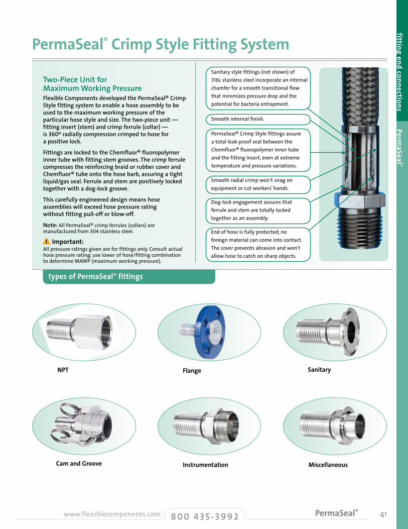
41
fitting end connections PermaSeal ®
types of PermaSeal® fittings
Two-Piece Unit for Maximum Working Pressure Flexible Components developed the PermaSeal® Crimp Style fitting system to enable a hose assembly to be used to the maximum working pressure of the particular hose style and size. The two-piece unit — fitting insert (stem) and crimp ferrule (collar) — is 360º radially compression crimped to hose for a positive lock.
Fittings are locked to the Chemfluor® fluoropolymer inner tube with fitting stem grooves. The crimp ferrule compresses the reinforcing braid or rubber cover and Chemfluor® tube onto the hose barb, assuring a tight liquid/gas seal. Ferrule and stem are positively locked together with a dog-lock groove.
This carefully engineered design means hose assemblies will exceed hose pressure rating without fitting pull-off or blow-off.
Note: All PermaSeal® crimp ferrules (collars) are manufactured from 304stainless steel.
All pressure ratings given are for fittings only. Consult actual hose pressure rating; use lower of hose/fitting combination to determine MAWP (maximum working pressure).
PermaSeal® Crimp Style Fitting System
PermaSeal® Crimp Style fittings assure a total leak-proof seal between the Chemfluor® fluoropolymer inner tube and the fitting insert, even at extreme temperature and pressure variations.
Smooth internal finish.
Sanitary style fittings (not shown) of 316L stainless steel incorporate an internal chamfer for a smooth transitional flow that minimizes pressure drop and the potential for bacteria entrapment.
Smooth radial crimp won’t snag on equipment or cut workers’ hands.
Dog-lock engagement assures that ferrule and stem are totally locked together as an assembly.
End of hose is fully protected; no foreign material can come into contact. The cover prevents abrasion and won’t allow hose to catch on sharp objects.
NPT Flange
Instrumentation Miscellaneous
8 0 0 4 3 5 - 3 9 9 2www.flexiblecomponents.com PermaSeal®
! Important:
Cam and Groove
Sanitary
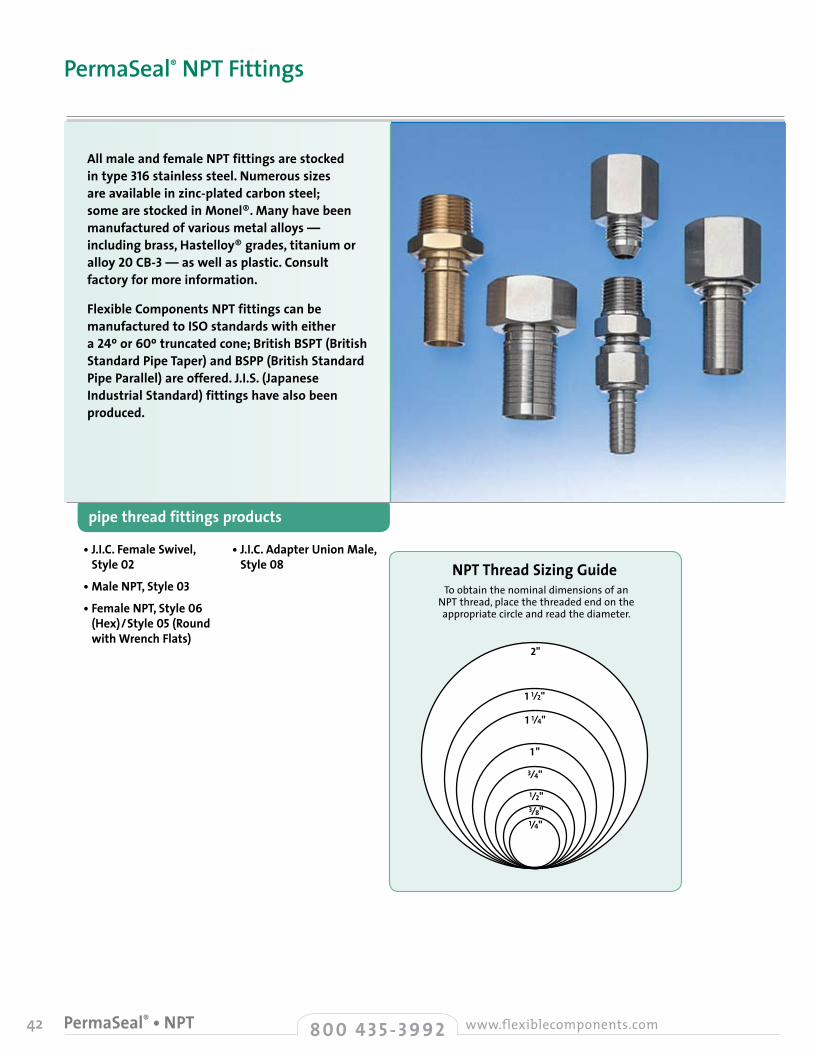
42 8 0 0 4 3 5 - 3 9 9 2 www.flexiblecomponents.comPermaSeal® • NPT
• J.I.C. Female Swivel, Style 02
• Male NPT, Style 03
• Female NPT, Style 06 (Hex) / Style 05 (Round with Wrench Flats)
• J.I.C. Adapter Union Male, Style 08
pipe thread fittings products
All male and female NPT fittings are stocked in type 316 stainless steel. Numerous sizes are available in zinc-plated carbon steel; some are stocked in Monel®. Many have been manufactured of various metal alloys — including brass, Hastelloy® grades, titanium or alloy 20 CB-3 — as well as plastic. Consult factory for more information.
Flexible Components NPT fittings can be manufactured to ISO standards with either a 24º or 60º truncated cone; British BSPT (British Standard Pipe Taper) and BSPP (British Standard Pipe Parallel) are offered. J.I.S. (Japanese Industrial Standard) fittings have also been produced.
PermaSeal® NPT Fittings
2"
1 1⁄2"
1 1⁄4"
1 "
3⁄4"
1⁄2"3⁄8"1⁄4"
To obtain the nominal dimensions of an NPT thread, place the threaded end on the appropriate circle and read the diameter.
NPT Thread Sizing Guide

43
fitting end connections PermaSeal ®
description standards
• J.I.C. female• SAE J514-37º sealing surface• Swivel fitting
• Joint Industrial Conference SAE J514
• Can be supplied with different materials in the wetted surface area; consult factory for more details
materials alternative styles
technical data
• 37º sealing surface machined to accept SAE taper of 45º in all sizes except 3/8" (-6) and 3/4" (-12), where threads differ
• Utilizing a female J.I.C. swivel style fitting with a J.I.C. by male pipe adapter results in a union fitting, enabling male by male or male by female FNPT connections to be made
• 316 stainless steel wetted surface
• 304 stainless steel swivel nut
• Standard zinc-plated steel available for WCS/BCS series hose (1/2"-2")
PermaSeal® J.I.C.J.I.C. Female Swivel • Style 02
A
I
J.I.C. Female Swivel fitting specifications • Style 02 A H I Inside Fitting Hex Inner J.I.C.
Part Diameter Length Size Dia. at Hose Thread
Number in. mm in. mm in. mm in. mm in. mm160202SKN
160402SKN
160402USKN
160602SKN
160802SKN
160802USKN
381202SKN
381602SKN
382002SKN
382402SKN
383202SKN
0.13
0.25
0.25
0.38
0.50
0.50
0.75
1.00
1.25
1.50
2.00
3.18
6.35
6.35
9.53
12.70
12.70
19.05
25.40
31.75
38.10
50.80
1.29
1.38
1.43
1.68
2.02
2.15
2.59
2.68
3.81
3.81
4.75
32.77
35.05
36.32
42.67
51.31
54.61
65.79
68.07
96.77
96.77
120.65
0.43
0.56
0.63
0.68
0.87
1.00
1.25
1.50
2.25
2.25
2.88
10.92
14.22
15.88
17.27
22.10
25.40
31.75
38.10
57.15
57.15
73.15
0.10
0.19
0.19
0.30
0.40
0.40
0.65
0.87
1.10
1.37
1.75
2.54
4.83
4.83
7.62
10.16
10.16
16.51
22.10
27.94
34.80
44.45
8 0 0 4 3 5 - 3 9 9 2www.flexiblecomponents.com PermaSeal® • J.I.C.
H
3/8
7/16
1/2
9/16
3/4
7/8
1-1/16
1-5/16
1-5/8
1-7/8
2-1/2
24
20
20
18
16
14
12
12
12
12
12
Style 02
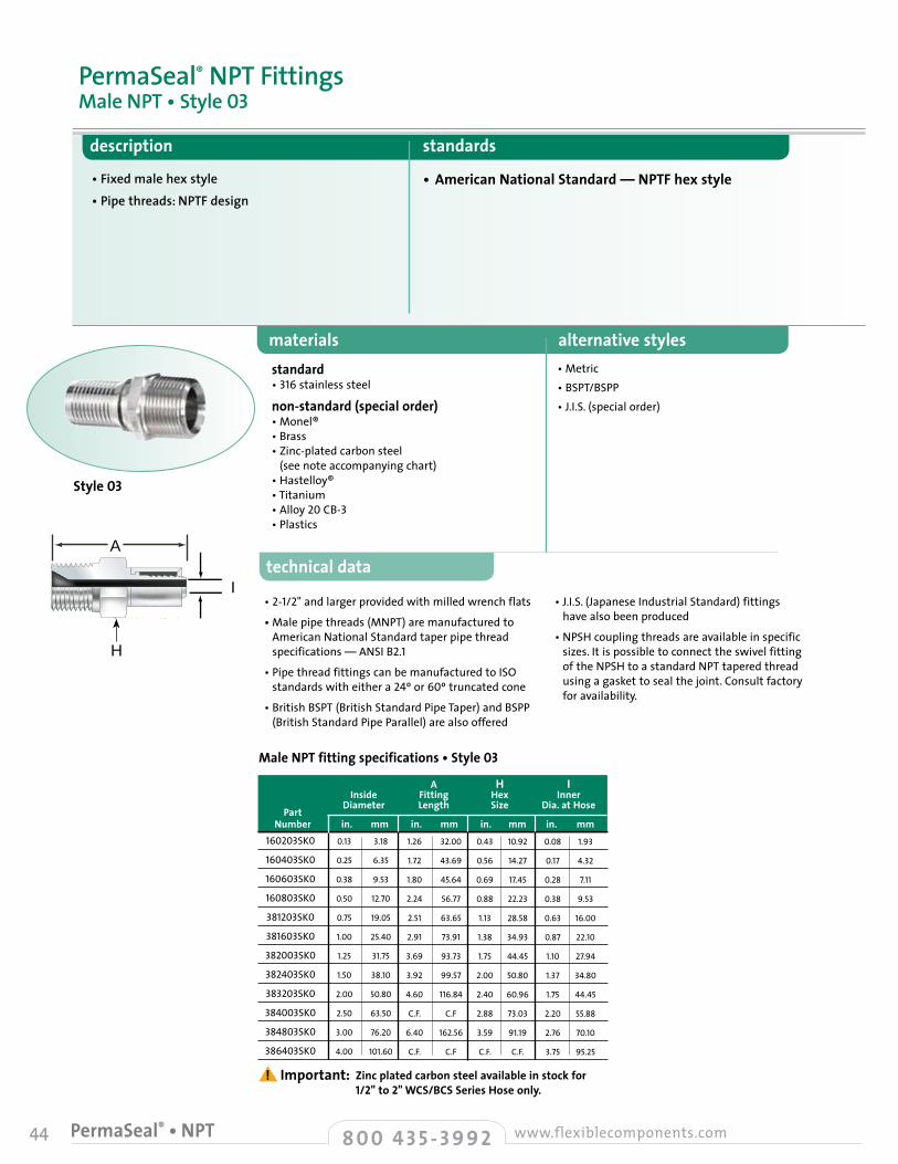
44 8 0 0 4 3 5 - 3 9 9 2 www.flexiblecomponents.comPermaSeal® • NPT
technical data
H ( Hex Size )
A
I
• Metric• BSPT/BSPP• J.I.S. (special order)
materials alternative stylesstandard • 316 stainless steel
non-standard (special order) • Monel®• Brass• Zinc-plated carbon steel
(see note accompanying chart)• Hastelloy®• Titanium• Alloy 20 CB-3• Plastics
Male NPT fitting specifications • Style 03
A H I Inside Fitting Hex Inner
Part Diameter Length Size Dia. at Hose
Number in. mm in. mm in. mm in. mm
Zinc plated carbon steel available in stock for 1/2" to 2" WCS/BCS Series Hose only.
160203SK0
160403SK0
160603SK0
160803SK0
381203SK0
381603SK0
382003SK0
382403SK0
383203SK0
384003SK0
384803SK0
386403SK0
0.13
0.25
0.38
0.50
0.75
1.00
1.25
1.50
2.00
2.50
3.00
4.00
3.18
6.35
9.53
12.70
19.05
25.40
31.75
38.10
50.80
63.50
76.20
101.60
1.26
1.72
1.80
2.24
2.51
2.91
3.69
3.92
4.60
C.F.
6.40
C.F.
32.00
43.69
45.64
56.77
63.65
73.91
93.73
99.57
116.84
C.F
162.56
C.F
0.43
0.56
0.69
0.88
1.13
1.38
1.75
2.00
2.40
2.88
3.59
C.F.
10.92
14.27
17.45
22.23
28.58
34.93
44.45
50.80
60.96
73.03
91.19
C.F.
0.08
0.17
0.28
0.38
0.63
0.87
1.10
1.37
1.75
2.20
2.76
3.75
1.93
4.32
7.11
9.53
16.00
22.10
27.94
34.80
44.45
55.88
70.10
95.25
description standards
• Fixed male hex style• Pipe threads: NPTF design
• American National Standard — NPTF hex style
PermaSeal® NPT FittingsMale NPT • Style 03
• J.I.S. (Japanese Industrial Standard) fittings have also been produced
• NPSH coupling threads are available in specific sizes. It is possible to connect the swivel fitting of the NPSH to a standard NPT tapered thread using a gasket to seal the joint. Consult factory for availability.
• 2-1/2" and larger provided with milled wrench flats
• Male pipe threads (MNPT) are manufactured to American National Standard taper pipe thread specifications — ANSI B2.1
• Pipe thread fittings can be manufactured to ISO standards with either a 24º or 60º truncated cone
• British BSPT (British Standard Pipe Taper) and BSPP (British Standard Pipe Parallel) are also offered
H
! Important:
Style 03
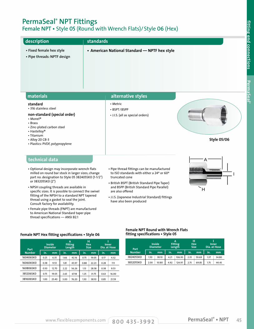
technical data
• Pipe thread fittings can be manufactured to ISO standards with either a 24º or 60º truncated cone
• British BSPT (British Standard Pipe Taper) and BSPP (British Standard Pipe Parallel) are also offered
• J.I.S. (Japanese Industrial Standard) fittings have also been produced
• Optional design may incorporate wrench flats milled on round bar stock in larger sizes; change part no. designation to Style 05 382405SK0(1-1/2") or 383205SK0(2")
• NPSH coupling threads are available in specific sizes. It is possible to connect the swivel fitting of the NPSH to a standard NPT tapered thread using a gasket to seal the joint. Consult factory for availability.
• Female pipe threads (FNPT) are manufactured to American National Standard taper pipe thread specifications — ANSI B2.1
45
fitting end connections PermaSeal ®
H (Hex Size)
materials alternative styles
description standards
• Fixed female hex style• Pipe threads: NPTF design
• American National Standard — NPTF hex style
standard • 316 stainless steel
non-standard (special order) • Monel®• Brass• Zinc-plated carbon steel • Hastelloy®• Titanium• Alloy 20 CB-3• Plastics: PVDF, polypropylene
• Metric
• BSPT/BSPP
• J.I.S.(all as special orders)
PermaSeal® NPT FittingsFemale NPT • Style 05 (Round with Wrench Flats)/ Style 06 (Hex)
Female NPT Hex fitting specifications • Style 06 A H I Inside Fitting Hex Inner
Part Diameter Length Size Dia. at Hose
Number in. mm in. mm in. mm in. mm160406SK0
160606SK0
160806SK0
381206SK0
381606SK0
0.25
0.38
0.50
0.75
1.00
6.35
9.53
12.70
19.05
25.40
1.66
1.81
2.22
2.65
3.00
42.16
45.97
56.26
67.18
76.20
0.75
0.88
1.13
1.25
1.50
19.05
22.23
28.58
31.75
38.10
0.17
0.28
0.38
0.63
0.85
4.32
7.11
9.53
16.00
21.59
Female NPT Round with Wrench Flats fitting specifications • Style 05
A H I Inside Fitting Hex Inner
Part Diameter Length Size Dia. at Hose
Number in. mm in. mm in. mm in. mm382405SK0
383205SK0
1.50
2.00
38.10
50.80
4.21
4.92
106.93
124.97
2.35
2.75
59.69
69.85
1.37
1.75
34.80
44.45
A
H
I
8 0 0 4 3 5 - 3 9 9 2www.flexiblecomponents.com PermaSeal® • NPT
Style 05/06

46 8 0 0 4 3 5 - 3 9 9 2 www.flexiblecomponents.comPermaSeal® • J.I.C.
technical data
• Also available Female Adapter Union, Style 07 (1/8"-1"); consult factory for availability
• Utilizing a female J.I.C. swivel style fitting with a J.I.C. by male adapter results in a union fitting, enabling male by male or male by female FNPT connections to be made
materials alternative styles
description standards
• Fixed male• Swivel male/female union style• Pipe threads: NPTF design
• American National Standard — NPTF hex style
standard • 316 stainless steel wetted surface
• 304stainless steel ferrule and nut
optional materials • Monel® • Brass • Zinc-plated carbon steel
• Metric
• BSPT/BSPP
• J.I.S. (special order)
PermaSeal® J.I.C.J.I.C. Adapter Union Male • Style 08
H D A Hose Fitting Hex 1 Hex 2 Fitting
Part Size Inner Diameter Size Size Length
Number in. mm in. mm in. mm in. mm in. mm
Consult factory for Style 07 female NPT union availability and technical information.
160208SK0
160408SK0
160608SK0
160808SK0
381208SK0
381608SK0
382408SK0
383208SK0
0.13
0.25
0.38
0.50
0.75
1.00
1.50
2.00
3.30
6.35
9.65
12.7
19.05
25.40
38.10
50.80
0.10
0.19
0.30
0.40
0.65
0.87
1.37
1.75
2.54
4.83
7.62
10.16
16.51
22.10
34.80
44.45
0.56
0.62
0.68
0.87
1.25
1.50
2.26
2.88
14.22
15.75
17.27
22.10
31.75
38.10
57.40
73.15
0.56
0.56
0.75
0.93
1.12
1.37
2.00
2.63
14.22
14.22
19.05
23.62
28.45
34.80
50.80
66.68
2.35
2.41
2.67
3.27
3.97
4.26
5.57
8.75
59.69
61.21
67.82
83.06
100.84
108.20
141.48
222.25
J.I.C. Adapter Union Male fitting specifications • Style 08
A
H (Hex Size)D (Hex Size)D H
A
! Important:
Style 08
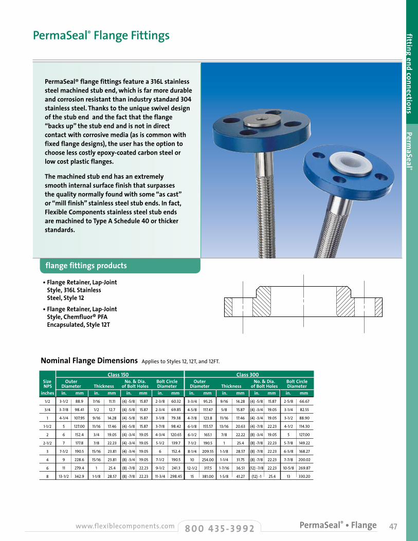
47
fitting end connections PermaSeal ®
• Flange Retainer, Lap-Joint Style, 316L Stainless Steel, Style 12
• Flange Retainer, Lap-Joint Style, Chemfluor® PFA Encapsulated, Style 12T
flange fittings products
PermaSeal® flange fittings feature a 316L stainless steel machined stub end, which is far more durable and corrosion resistant than industry standard 304 stainless steel. Thanks to the unique swivel design of the stub end and the fact that the flange “backs up” the stub end and is not in direct contact with corrosive media (as is common with fixed flange designs), the user has the option to choose less costly epoxy-coated carbon steel or low cost plastic flanges.
The machined stub end has an extremely smooth internal surface finish that surpasses the quality normally found with some “as cast” or “mill finish” stainless steel stub ends. In fact, Flexible Components stainless steel stub ends are machined to Type A Schedule 40 or thicker standards.
PermaSeal® Flange Fittings
Nominal Flange Dimensions Applies to Styles12,12T,and 12FT.
Class 150 Class 300 Size Outer No. & Dia. Bolt Circle Outer No. & Dia. Bolt Circle NPS Diameter Thickness of Bolt Holes Diameter Diameter Thickness of Bolt Holes Diameterinches in. mm in. mm in. mm in. mm in. mm in. mm in. mm in. mm
1/2
3/4
1
1-1/2
2
2-1/2
3
4
6
8
3-1/2
3-7/8
4-1/4
5
6
7
7-1/2
9
11
13-1/2
88.9
98.41
107.95
127.00
152.4
177.8
190.5
228.6
279.4
342.9
7/16
1/2
9/16
11/16
3/4
7/8
15/16
15/16
1
1-1/8
11.11
12.7
14.28
17.46
19.05
22.23
23.81
23.81
25.4
28.57
(4)-5/8
(4)-5/8
(4)-5/8
(4)-5/8
(4)-3/4
(4)-3/4
(4)-3/4
(8)-3/4
(8)-7/8
(8)-7/8
15.87
15.87
15.87
15.87
19.05
19.05
19.05
19.05
22.23
22.23
2-3/8
2-3/4
3-1/8
3-7/8
4-3/4
5-1/2
6
7-1/2
9-1/2
11-3/4
60.32
69.85
79.38
98.42
120.65
139.7
152.4
190.5
241.3
298.45
3-3/4
4-5/8
4-7/8
6-1/8
6-1/2
7-1/2
8-1/4
10
12-1/2
15
95.25
117.47
123.8
155.57
165.1
190.5
209.55
254.00
317.5
381.00
9/16
5/8
11/16
13/16
7/8
1
1-1/8
1-1/4
1-7/16
1-5/8
14.28
15.87
17.46
20.63
22.22
25.4
28.57
31.75
36.51
41.27
(4)-5/8
(4)-3/4
(4)-3/4
(4)-7/8
(8)-3/4
(8)-7/8
(8)-7/8
(8)-7/8
(12)-7/8
(12)-1
15.87
19.05
19.05
22.23
19.05
22.23
22.23
22.23
22.23
25.4
2-5/8
3-1/4
3-1/2
4-1/2
5
5-7/8
6-5/8
7-7/8
10-5/8
13
66.67
82.55
88.90
114.30
127.00
149.22
168.27
200.02
269.87
330.20
8 0 0 4 3 5 - 3 9 9 2www.flexiblecomponents.com PermaSeal® • Flange
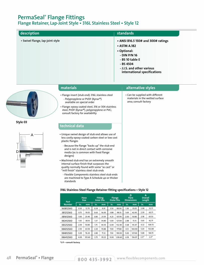
48 8 0 0 4 3 5 - 3 9 9 2 www.flexiblecomponents.comPermaSeal® • Flange
A
D
description standards
• Swivel flange, lap-joint style • ANSI B16.5 150# and 300# ratings• ASTM A.182• Optional: - DIN P/N 16 - BS 10 table E - BS 4504 - J.I.S. and other various
international specifications
• Can be supplied with different materials in the wetted surface area; consult factory
materials alternative styles
• Flange insert (stub end): 316L stainless steel - Polypropylene or PVDF (Kynar®)
available on special order
• Flange: epoxy coated steel, 316 or 304stainless steel, PVDF (Kynar®), polypropylene or PVC; consult factory for availability
PermaSeal® Flange FittingsFlange Retainer, Lap-Joint Style • 316L Stainless Steel • Style 12
D A Hose Fitting Flange Flare Overall
Part Size Inner Dia. Outer Dia. Dimensions Length
Number in. mm in. mm in. mm in. mm in. mm
*C/F – consult factory.
160812SK0
381212SK0
381612SK0
382412SK0
383212SK0
384012SK0
384812SK0
386412SK0
0.50
0.75
1.00
1.50
2.00
2.50
3.00
4.00
12.70
19.05
25.40
38.10
50.80
63.50
76.20
101.60
0.39
0.63
0.85
1.37
1.75
2.20
2.80
3.75
9.91
16.00
21.59
34.80
44.45
55.88
71.12
95.25
3.50
3.88
4.25
5.00
6.00
7.00
7.50
9.00
88.90
98.55
107.95
127.00
152.40
177.80
190.50
228.60
1.38
1.69
2.00
2.88
3.68
4.13
5.00
6.18
35.05
42.93
50.80
73.15
93.47
104.90
127.00
156.97
2.08
2.39
2.58
3.65
4.32
5.20
5.68
C/F*
52.71
60.71
65.53
92.71
109.73
132.08
144.15
C/F*
316L Stainless Steel Flange Retainer fitting specifications • Style 12
D
A
technical data
• Unique swivel design of stub end allows use of less costly epoxy-coated carbon steel or low cost plastic flanges
- Because the flange "backs up" the stub end and is not in direct contact with corrosive media (as is common with fixed flange designs)
• Machined stub end has an extremely smooth internal surface finish that surpasses the quality normally found with some “as cast” or “mill finish” stainless steel stub ends
- Flexible Components stainless steel stub ends are machined to Type A Schedule 40 or thicker standards
Style 03
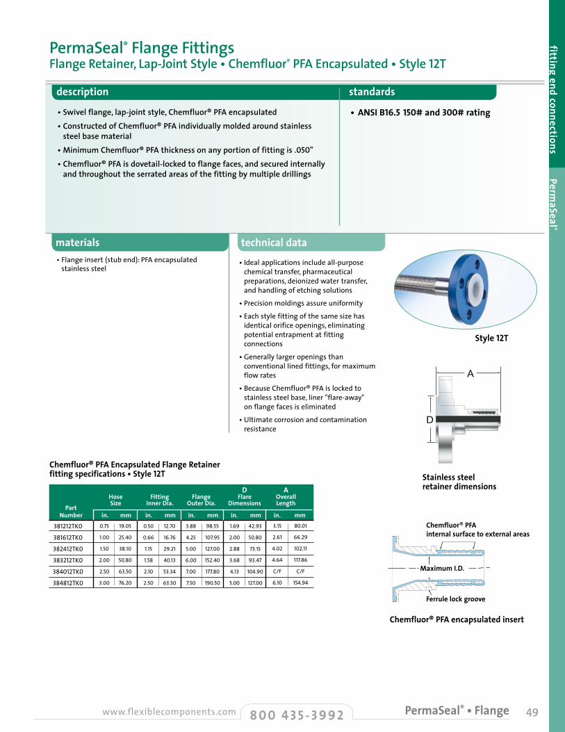
technical datamaterials
49
description standards
• Swivel flange, lap-joint style, Chemfluor® PFA encapsulated• Constructed of Chemfluor® PFA individually molded around stainless
steel base material• Minimum Chemfluor® PFA thickness on any portion of fitting is .050"• Chemfluor® PFA is dovetail-locked to flange faces, and secured internally
and throughout the serrated areas of the fitting by multiple drillings
• ANSI B16.5 150# and 300# rating
PermaSeal® Flange FittingsFlange Retainer, Lap-Joint Style • Chemfluor® PFA Encapsulated • Style 12T
fitting end connections PermaSeal ®
• Flange insert (stub end): PFA encapsulatedstainless steel
• Ideal applications include all-purpose chemical transfer, pharmaceutical preparations, deionized water transfer, and handling of etching solutions
• Precision moldings assure uniformity
• Each style fitting of the same size has identical orifice openings, eliminating potential entrapment at fitting connections
• Generally larger openings than conventional lined fittings, for maximum flow rates
• Because Chemfluor® PFA is locked to stainless steel base, liner "flare-away" on flange faces is eliminated
• Ultimate corrosion and contamination resistance
Ferrule lock groove.
Maximum I.D.
Teflon internal surfaceto external areas
D A Hose Fitting Flange Flare Overall
Part Size Inner Dia. Outer Dia. Dimensions Length
Number in. mm in. mm in. mm in. mm in. mm
381212TK0
381612TK0
382412TK0
383212TK0
384012TK0
384812TK0
0.75
1.00
1.50
2.00
2.50
3.00
19.05
25.40
38.10
50.80
63.50
76.20
0.50
0.66
1.15
1.58
2.10
2.50
12.70
16.76
29.21
40.13
53.34
63.50
3.88
4.25
5.00
6.00
7.00
7.50
98.55
107.95
127.00
152.40
177.80
190.50
1.69
2.00
2.88
3.68
4.13
5.00
42.93
50.80
73.15
93.47
104.90
127.00
3.15
2.61
4.02
4.64
C/F
6.10
80.01
66.29
102.11
117.86
C/F
154.94
Chemfluor® PFA Encapsulated Flange Retainer fitting specifications • Style 12T
A
DD
A
8 0 0 4 3 5 - 3 9 9 2www.flexiblecomponents.com PermaSeal® • Flange
Ferrule lock groove
Stainless steel retainer dimensions
Chemfluor® PFA encapsulated insert
Maximum I.D.
Chemfluor® PFA internal surface to external areas
Style 12T
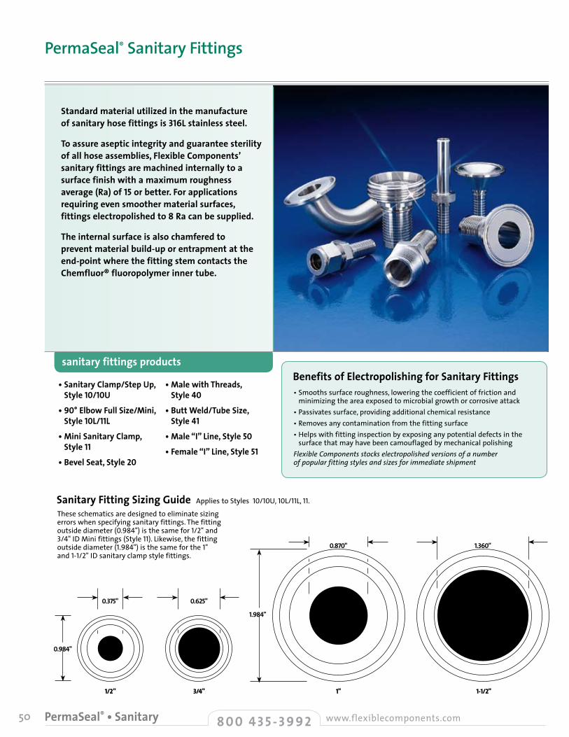
50 8 0 0 4 3 5 - 3 9 9 2 www.flexiblecomponents.comPermaSeal® • Sanitary
• Sanitary Clamp/Step Up, Style 10/10U
• 90° Elbow Full Size/Mini, Style 10L/11L
• Mini Sanitary Clamp, Style 11
• Bevel Seat, Style 20
• Male with Threads, Style 40
• Butt Weld/Tube Size, Style 41
• Male “I” Line, Style 50
• Female “I” Line, Style 51
Sanitary Fitting Sizing Guide Applies to Styles10/10U,10L/11L,11.
0.984"
1.984"
1/2 " 3/4" 1" 1-1/2"
0.375" 0.625"
0.870" 1.360"
These schematics are designed to eliminate sizing errors when specifying sanitary fittings. The fitting outside diameter (0.984") is the same for 1/2" and 3/4" ID Mini fittings (Style 11). Likewise, the fitting outside diameter (1.984") is the same for the 1" and 1-1/2"ID sanitary clamp style fittings.
sanitary fittings products
Standard material utilized in the manufacture of sanitary hose fittings is 316L stainless steel.
To assure aseptic integrity and guarantee sterility of all hose assemblies, Flexible Components’ sanitary fittings are machined internally to a surface finish with a maximum roughness average (Ra) of 15 or better. For applications requiring even smoother material surfaces, fittings electropolished to 8 Ra can be supplied.
The internal surface is also chamfered to prevent material build-up or entrapment at the end-point where the fitting stem contacts the Chemfluor® fluoropolymer inner tube.
PermaSeal® Sanitary Fittings
Benefits of Electropolishing for Sanitary Fittings• Smooths surface roughness, lowering the coefficient of friction and
minimizing the area exposed to microbial growth or corrosive attack• Passivates surface, providing additional chemical resistance• Removes any contamination from the fitting surface• Helps with fitting inspection by exposing any potential defects in the
surface that may have been camouflaged by mechanical polishingFlexible Components stocks electropolished versions of a number of popular fitting styles and sizes for immediate shipment
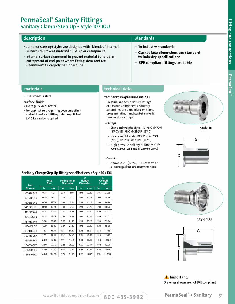
description standards
• Jump (or step-up) styles are designed with “blended” internal surfaces to prevent material build-up or entrapment
• Internal surface chamfered to prevent material build-up or entrapment at end-point where fitting stem contacts Chemfluor® fluoropolymer inner tube
• To industry standards• Gasket face dimensions are standard
to industry specifications• BPE compliant fittings available
materials technical data
temperature/pressure ratings• Pressure and temperature ratings
of Flexible Components’ sanitary assemblies are dependent on clamp pressure ratings and gasket material temperature ratings
• Clamps: - Standard weight style: 150 PSIG @ 70ºF
(21ºC); 125 PSIG @ 250ºF (121ºC) - Heavyweight style: 500 PSIG @ 70ºF
(21ºC); 125 PSIG @ 250ºF (121ºC) - High pressure bolt style: 1500 PSIG @
70ºF (21ºC); 125 PSIG @ 250ºF (121ºC)
• Gaskets: - Above 250ºF (121ºC), PTFE, Viton® or
silicone gaskets are recommended
• 316L stainless steel
surface finish • Average 15 Ra or better• For applications requiring even smoother
material surfaces, fittings electropolished to 10 Ra can be supplied
PermaSeal® Sanitary FittingsSanitary Clamp/Step Up • Style 10 / 10U
A
D
A
D
Sanitary Clamp/Step Up fitting specifications • Style 10/10U D A Hose Fitting Inner Flange Overall
Part Size Diameter Diameter Length
Number in. mm in. mm in. mm in. mm 0.25
0.38
0.50
0.50
0.75
0.75
1.00
1.00
1.50
1.50
2.00
2.50
3.00
4.00
6.35
9.53
12.70
12.70
19.05
19.05
25.40
25.40
38.10
38.10
50.80
63.50
76.20
101.60
0.19
0.28
0.38
0.38
0.65
0.65
0.87
0.87
1.37
1.37
1.75
2.22
2.80
3.75
4.83
7.11
9.53
9.53
16.51
16.51
22.10
22.10
34.67
34.67
44.45
56.39
71.12
95.25
1.98
1.98
1.98
1.98
1.98
1.98
1.98
1.98
2.52
2.51
2.50
3.05
3.58
4.68
50.29
50.29
50.29
50.29
50.29
50.29
50.29
50.29
63.91
63.75
63.50
77.47
90.93
118.75
1.46
1.90
1.90
1.90
2.39
2.39
2.24
2.30
2.88
2.88
4.00
4.02
4.54
5.16
37.08
48.26
48.26
48.26
60.71
60.71
56.90
58.29
73.15
73.15
101.60
102.11
115.19
130.94
160410SK0
160610SK0
160810SK0
160810USK
381210SK0
381210USK
381610SK0
381610USK
382410SK0
382410USK
383210SK0
384010SK0
384810SK0
386410SK0
51
fitting end connections PermaSeal ®
8 0 0 4 3 5 - 3 9 9 2www.flexiblecomponents.com PermaSeal® • Sanitary
A
D
A
D
Drawings shown are not BPE compliant ! Important:
Style 10
Style 10U
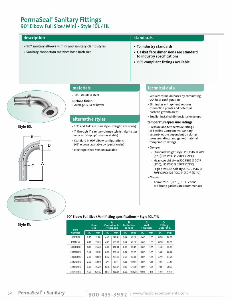
52 8 0 0 4 3 5 - 3 9 9 2 www.flexiblecomponents.comPermaSeal® • Sanitary
description standards
• 90º sanitary elbows in mini and sanitary clamp styles• Sanitary connection matches hose barb size
• To industry standards• Gasket face dimensions are standard
to industry specifications• BPE compliant fittings available
materials technical data• Reduces strain on hoses by eliminating 90º hose configuration
• Eliminates entrapment, reduces connection points and potential bacteria growth areas
• Smaller installed dimensional envelope
temperature/pressure ratings• Pressure and temperature ratings
of Flexible Components’ sanitary assemblies are dependent on clamp pressure ratings and gasket material temperature ratings
• Clamps: - Standard weight style: 150 PSIG @ 70ºF
(21ºC); 125 PSIG @ 250ºF (121ºC) - Heavyweight style: 500 PSIG @ 70ºF
(21ºC); 125 PSIG @ 250ºF (121ºC) - High pressure bolt style: 1500 PSIG @
70ºF (21ºC); 125 PSIG @ 250ºF (121ºC) • Gaskets: - Above 250ºF (121ºC), PTFE, Viton®
or silicone gaskets are recommended
• 316L stainless steel
surface finish • Average 15 Ra or better
alternative styles• 1/2" and 3/4" are mini style (straight sizes only)
• 1" through 4" sanitary clamp style (straight sizes only, no “step up” sizes available)
• Standard in 90º elbow configurations (45º elbows available by special order)
• Electropolished version available
PermaSeal® Sanitary Fittings90° Elbow Full Size/Mini • Style 10L / 11L
90˚ Elbow Full Size / Mini fitting specifications • Style 10L / 11L A B C D Hose Centerline to Centerline Wall Fitting
Part Size Fitting End to Face Thickness Outer Dia.
Number in. mm in. mm in. mm in. mm in. mm0.50
0.75
1.00
1.50
2.00
2.50
3.00
4.00
12.70
19.05
25.40
38.10
50.80
63.50
76.20
101.60
4.47
4.73
4.90
6.36
8.02
C/F
10.16
12.61
113.41
120.02
124.33
161.54
203.58
C/F
258.04
320.24
1.63
1.63
2.00
2.75
3.50
4.25
5.00
6.63
41.28
41.28
50.80
69.85
88.90
107.95
127.00
168.28
0.07
0.07
0.07
0.07
0.07
0.07
0.07
0.08
1.65
1.65
1.65
1.65
1.65
1.65
1.65
2.11
160811LSK
161211LSK
381610LSK
382410LSK
383210LSK
384010LSK
384810LSK
386410LSK
0.98
0.98
1.98
1.98
2.49
3.05
3.58
4.68
24.89
24.89
50.29
50.29
63.25
77.47
90.93
118.75
B
A
D
C
B
A
D
C
Style 10L
Style 11L
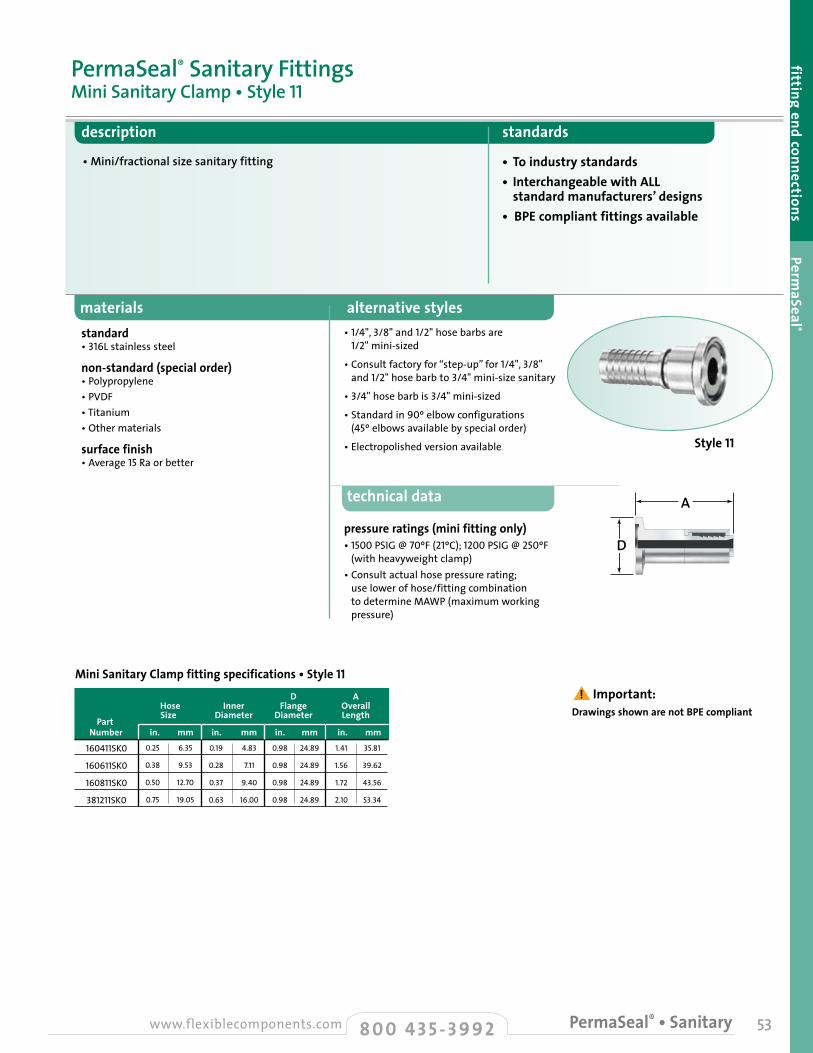
53
fitting end connections PermaSeal ®
materials alternative styles
description standards
• Mini/fractional size sanitary fitting • To industry standards• Interchangeable with ALL
standard manufacturers’ designs• BPE compliant fittings available
standard • 316L stainless steel
non-standard (special order) • Polypropylene• PVDF• Titanium• Other materials
surface finish • Average 15 Ra or better
• 1/4",3/8" and 1/2" hose barbs are 1/2" mini-sized
• Consult factory for “step-up” for1/4", 3/8"and 1/2" hose barb to 3/4" mini-size sanitary
• 3/4" hose barb is 3/4" mini-sized
• Standard in 90º elbow configurations (45º elbows available by special order)
• Electropolished version available
PermaSeal® Sanitary FittingsMini Sanitary Clamp • Style 11
technical data
pressure ratings (mini fitting only)• 1500 PSIG @ 70ºF (21ºC); 1200 PSIG @ 250ºF
(with heavyweight clamp)• Consult actual hose pressure rating;
use lower of hose/fitting combination to determine MAWP (maximum working pressure)
A
D
Mini Sanitary Clamp fitting specifications • Style 11 D A Hose Inner Flange Overall
Part Size Diameter Diameter Length
Number in. mm in. mm in. mm in. mm 0.25
0.38
0.50
0.75
6.35
9.53
12.70
19.05
0.19
0.28
0.37
0.63
4.83
7.11
9.40
16.00
0.98
0.98
0.98
0.98
24.89
24.89
24.89
24.89
1.41
1.56
1.72
2.10
35.81
39.62
43.56
53.34
160411SK0
160611SK0
160811SK0
381211SK0
A
D
8 0 0 4 3 5 - 3 9 9 2www.flexiblecomponents.com PermaSeal® • Sanitary
Drawings shown are not BPE compliant ! Important:
Style 11
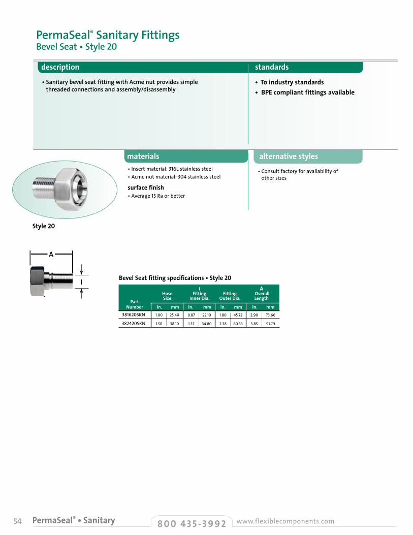
54 8 0 0 4 3 5 - 3 9 9 2 www.flexiblecomponents.comPermaSeal® • Sanitary
alternative styles
• Consult factory for availability of other sizes
materials
description standards
• Sanitary bevel seat fitting with Acme nut provides simple threaded connections and assembly/disassembly
• To industry standards• BPE compliant fittings available
• Insert material: 316L stainless steel• Acme nut material: 304 stainless steel
surface finish• Average 15 Ra or better
PermaSeal® Sanitary FittingsBevel Seat • Style 20
Bevel Seat fitting specifications • Style 20 I A Hose Fitting Fitting Overall
Part Size Inner Dia. Outer Dia. Length
Number in. mm in. mm in. mm in. mm 381620SKN
382420SKN
1.00
1.50
25.40
38.10
0.87
1.37
22.10
34.80
1.80
2.38
45.72
60.33
2.90
3.85
73.66
97.79
A
I
Style 20

55
fitting end connections PermaSeal ®
alternative styles• Consult factory for availability of
other sizes
description standards
• Internal surface chamfered to prevent material build-up or entrapment at end-point where fitting stem contacts Chemfluor® fluoropolymer inner tube
• To industry standards • BPE compliant fittings available
materials• 316L stainless steel
surface finish • Average 15 Ra or better• For applications requiring even smoother
material surfaces, fittings electropolished to 10 Ra can be supplied.
PermaSeal® Sanitary FittingsMale with Threads • Style 40
A
B IMale with Threads fitting specifications • Style 40
I B A Hose Fitting Fitting Overall Part Size Inner Dia. Outer Dia. Length Number in. mm in. mm in. mm in. mm 381640SK0
382440SK0
1.00
1.50
25.40
38.10
0.85
1.37
22.10
34.80
1.46
1.99
37.08
50.55
2.38
3.40
60.33
86.36
8 0 0 4 3 5 - 3 9 9 2www.flexiblecomponents.com PermaSeal® • Sanitary
Style 40
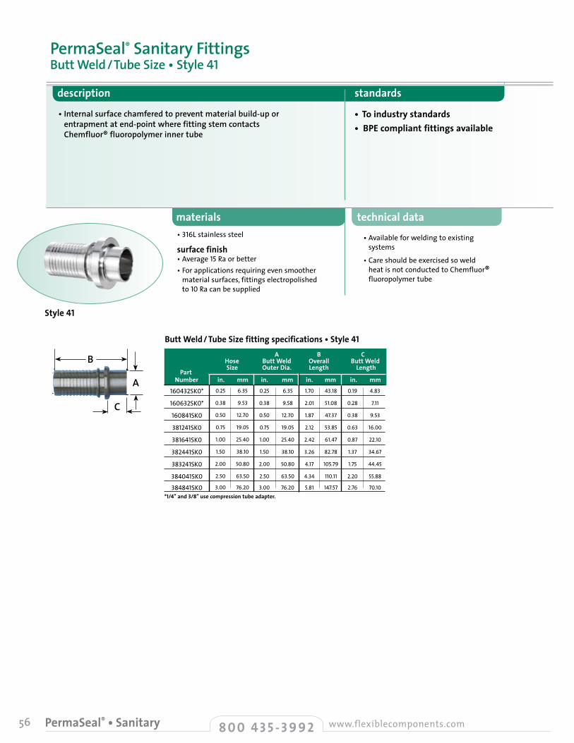
56 8 0 0 4 3 5 - 3 9 9 2 www.flexiblecomponents.comPermaSeal® • Sanitary
technical data
• Available for welding to existing systems
• Care should be exercised so weld heat is not conducted to Chemfluor® fluoropolymer tube
materials
description standards
• Internal surface chamfered to prevent material build-up or entrapment at end-point where fitting stem contacts Chemfluor® fluoropolymer inner tube
• To industry standards • BPE compliant fittings available
• 316L stainless steel
surface finish • Average 15 Ra or better• For applications requiring even smoother
material surfaces, fittings electropolished to 10 Ra can be supplied
PermaSeal® Sanitary FittingsButt Weld/Tube Size • Style 41
C
Butt Weld/ Tube Size fitting specifications • Style 41 A B C Hose Butt Weld Overall Butt Weld
Part Size Outer Dia. Length Length
Number in. mm in. mm in. mm in. mm
*1/4" and 3/8" use compression tube adapter.
0.25
0.38
0.50
0.75
1.00
1.50
2.00
2.50
3.00
6.35
9.53
12.70
19.05
25.40
38.10
50.80
63.50
76.20
0.25
0.38
0.50
0.75
1.00
1.50
2.00
2.50
3.00
6.35
9.58
12.70
19.05
25.40
38.10
50.80
63.50
76.20
43.18
51.08
47.37
53.85
61.47
82.78
105.79
110.11
147.57
0.19
0.28
0.38
0.63
0.87
1.37
1.75
2.20
2.76
4.83
7.11
9.53
16.00
22.10
34.67
44.45
55.88
70.10
1.70
2.01
1.87
2.12
2.42
3.26
4.17
4.34
5.81
160432SK0*
160632SK0*
160841SK0
381241SK0
381641SK0
382441SK0
383241SK0
384041SK0
384841SK0
Style 41
B
A
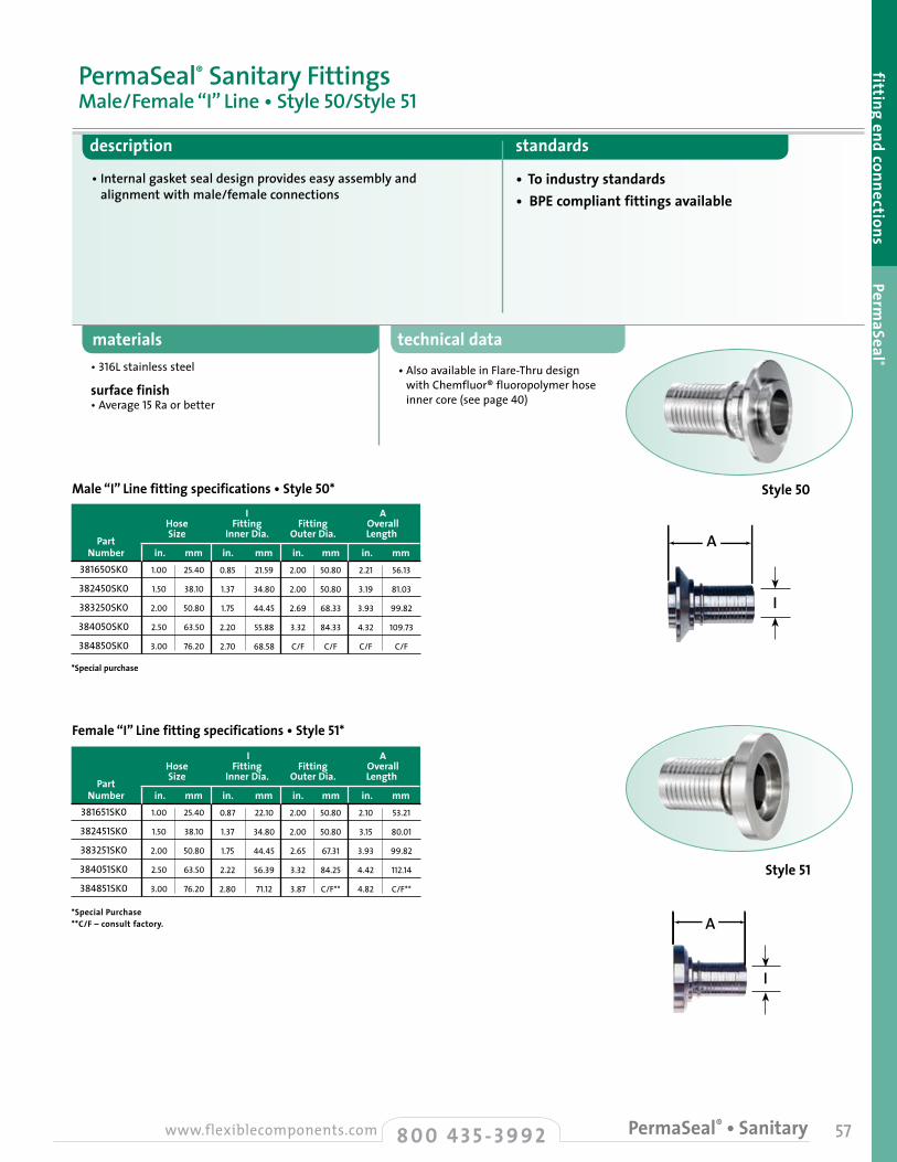
57
description standards
• Internal gasket seal design provides easy assembly and alignment with male/female connections
• To industry standards• BPE compliant fittings available
materials technical data• Also available in Flare-Thru design
with Chemfluor® fluoropolymer hose inner core (see page 40)
• 316L stainless steel
surface finish • Average 15 Ra or better
PermaSeal® Sanitary FittingsMale/Female “I” Line • Style 50/Style 51
fitting end connections PermaSeal ®
A
Male “I” Line fitting specifications • Style 50* I A Hose Fitting Fitting Overall
Part Size Inner Dia. Outer Dia. Length
Number in. mm in. mm in. mm in. mm
*Special purchase
381650SK0
382450SK0
383250SK0
384050SK0
384850SK0
1.00
1.50
2.00
2.50
3.00
25.40
38.10
50.80
63.50
76.20
0.85
1.37
1.75
2.20
2.70
21.59
34.80
44.45
55.88
68.58
2.00
2.00
2.69
3.32
C/F
50.80
50.80
68.33
84.33
C/F
2.21
3.19
3.93
4.32
C/F
56.13
81.03
99.82
109.73
C/F
I
I
A
Female “I” Line fitting specifications • Style 51*
I A Hose Fitting Fitting Overall
Part Size Inner Dia. Outer Dia. Length
Number in. mm in. mm in. mm in. mm
*Special Purchase **C/F – consult factory.
381651SK0
382451SK0
383251SK0
384051SK0
384851SK0
1.00
1.50
2.00
2.50
3.00
25.40
38.10
50.80
63.50
76.20
0.87
1.37
1.75
2.22
2.80
22.10
34.80
44.45
56.39
71.12
2.00
2.00
2.65
3.32
3.87
50.80
50.80
67.31
84.25
C/F**
2.10
3.15
3.93
4.42
4.82
53.21
80.01
99.82
112.14
C/F**
8 0 0 4 3 5 - 3 9 9 2www.flexiblecomponents.com PermaSeal® • Sanitary
Style 50
Style 51
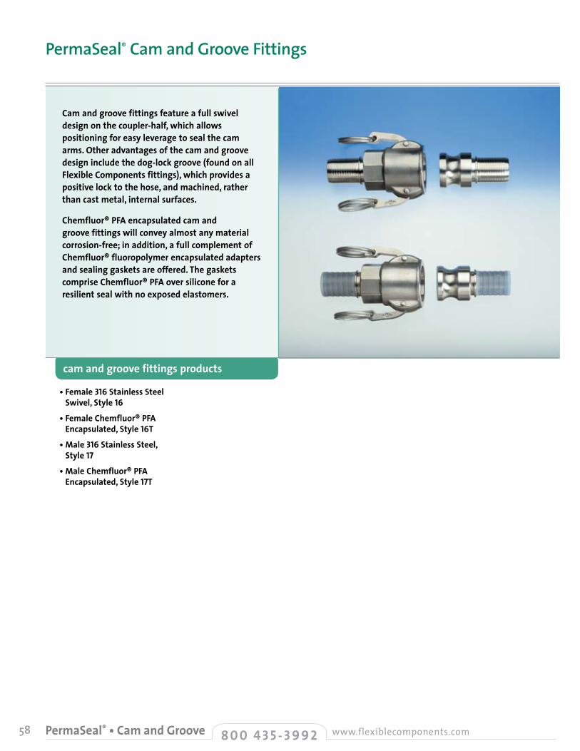
58 8 0 0 4 3 5 - 3 9 9 2 www.flexiblecomponents.comPermaSeal® • Cam and Groove
• Female 316 Stainless Steel Swivel, Style 16
• Female Chemfluor® PFA Encapsulated, Style 16T
• Male 316 Stainless Steel, Style 17
• Male Chemfluor® PFA Encapsulated, Style 17T
cam and groove fittings products
Cam and groove fittings feature a full swivel design on the coupler-half, which allows positioning for easy leverage to seal the cam arms. Other advantages of the cam and groove design include the dog-lock groove (found on all Flexible Components fittings), which provides a positive lock to the hose, and machined, rather than cast metal, internal surfaces.
Chemfluor® PFA encapsulated cam and groove fittings will convey almost any material corrosion-free; in addition, a full complement of Chemfluor® fluoropolymer encapsulated adapters and sealing gaskets are offered. The gaskets comprise Chemfluor® PFA over silicone for a resilient seal with no exposed elastomers.
PermaSeal® Cam and Groove Fittings
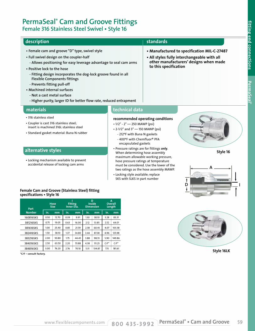
alternative styles
• Locking mechanism available to prevent accidental release of locking cam arms
59
description standards
• Female cam and groove “D” type, swivel style• Full swivel design on the coupler-half - Allows positioning for easy leverage advantage to seal cam arms• Positive lock to the hose - Fitting design incorporates the dog-lock groove found in all
Flexible Components fittings - Prevents fitting pull-off• Machined internal surfaces - Not a cast metal surface - Higher purity, larger ID for better flow rate, reduced entrapment
• Manufactured to specification MIL-C-27487• All styles fully interchangeable with all
other manufacturers’ designs when made to this specification
materials technical data
recommended operating conditions• 1/2"-2" — 250 MAWP (psi)• 2-1/2" and 3" — 150MAWP (psi) - 212ºF with Buna N gaskets - 400ºF with Chemfluor® PFA
encapsulated gaskets• Pressure ratings are for fittings only.
When determining hose assembly maximum allowable working pressure, hose pressure ratings at temperature must be considered. Use the lower of the two ratings as the hose assembly MAWP.
• Locking style available; replace SKS with SLKS in part number
• 316 stainless steel
• Coupler is cast 316 stainless steel; insert is machined 316L stainless steel
• Standard gasket material: Buna N rubber
PermaSeal® Cam and Groove FittingsFemale 316 Stainless Steel Swivel • Style 16
fitting end connections PermaSeal ®
D
A
I
I D A Hose Fitting Inside Overall
Part Size Inner Dia. Dimension Length
Number in. mm in. mm in. mm in. mm
*C/F – consult factory.
0.50
0.75
1.00
1.50
2.00
2.50
3.00
12.70
19.05
25.40
38.10
50.80
63.50
76.20
0.39
0.63
0.85
1.37
1.75
2.20
2.76
9.91
16.00
21.59
34.80
44.45
55.88
70.10
1.50
2.12
2.38
3.44
3.88
4.38
5.31
38.10
53.85
60.45
87.38
98.55
111.25
134.87
160816SKS
381216SKS
381616SKS
382416SKS
383216SKS
384016SKS
384816SKS
Female Cam and Groove (Stainless Steel) fitting specifications • Style 16
3.28
2.52
4.07
4.96
5.90
C/F*
7.15
83.31
64.01
103.38
125.98
149.86
C/F*
181.61
8 0 0 4 3 5 - 3 9 9 2www.flexiblecomponents.com PermaSeal® • Cam and Groove
Style 16
Style 16LK
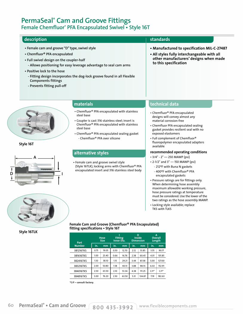
60 8 0 0 4 3 5 - 3 9 9 2 www.flexiblecomponents.comPermaSeal® • Cam and Groove
alternative styles
• Female cam and groove swivel style (Style 16TLK), locking arms with Chemfluor® PFA encapsulated insert and316 stainless steel body
technical data
• Chemfluor® PFA encapsulated designs will convey almost any material corrosion-free
• Chemfluor PFA encapsulated sealing gasket provides resilient seal with no exposed elastomers
• Full complement of Chemfluor® fluoropolymer encapsulated adapters available
recommended operating conditions• 3/4"-2" — 250 MAWP (psi)• 2-1/2" and 3"—150 MAWP (psi) - 212ºF with Buna N gaskets - 400ºF with Chemfluor® PFA
encapsulated gaskets• Pressure ratings are for fittings only.
When determining hose assembly maximum allowable working pressure, hose pressure ratings at temperature must be considered. Use the lower of the two ratings as the hose assembly MAWP.
• Locking style available; replace TKS with TLKS
materials
description standards
• Female cam and groove “D” type, swivel style• Chemfluor® PFA encapsulated• Full swivel design on the coupler-half - Allows positioning for easy leverage advantage to seal cam arms• Positive lock to the hose - Fitting design incorporates the dog-lock groove found in all Flexible
Components fittings - Prevents fitting pull-off
• Manufactured to specification MIL-C-27487• All styles fully interchangeable with all
other manufacturers’ designs when made to this specification
• Chemfluor® PFA encapsulated with stainless steel base
• Coupler is cast 316 stainless steel; insert is Chemfluor® PFA encapsulated with stainless steel base
• Chemfluor® PFA encapsulated sealing gasket - Chemfluor® PFA over silicone
PermaSeal® Cam and Groove FittingsFemale Chemfluor® PFA Encapsulated Swivel • Style 16T
I D A Hose Fitting Inside Overall
Part Size Inner Dia. Dimension Length
Number in. mm in. mm in. mm in. mm
*C/F – consult factory.
0.75
1.00
1.50
2.00
2.50
3.00
19.05
25.40
38.10
50.80
63.50
76.20
0.50
0.66
1.15
1.58
2.10
2.50
12.70
16.76
29.21
40.13
53.34
63.50
2.12
2.38
3.44
3.88
4.38
5.31
53.85
60.45
87.38
98.55
111.25
134.87
381216TKS
381616TKS
382416TKS
383216TKS
384016TKS
384816TKS
Female Cam and Groove (Chemfluor® PFA Encapsulated) fitting specifications • Style 16T
3.55
4.01
5.00
6.02
C/F*
7.19
90.17
101.85
127.00
152.91
C/F*
182.63
D
A
I
Style 16T
Style 16TLK
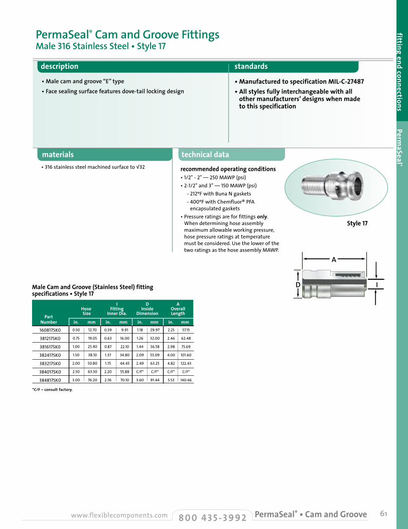
61
description standards
• Male cam and groove “E” type• Face sealing surface features dove-tail locking design
• Manufactured to specification MIL-C-27487• All styles fully interchangeable with all
other manufacturers’ designs when made to this specification
materials technical data
recommended operating conditions• 1/2"-2" — 250 MAWP (psi)• 2-1/2" and 3"—150 MAWP (psi) - 212ºF with Buna N gaskets - 400ºF with Chemfluor® PFA
encapsulated gaskets• Pressure ratings are for fittings only.
When determining hose assembly maximum allowable working pressure, hose pressure ratings at temperature must be considered. Use the lower of the two ratings as the hose assembly MAWP.
• 316 stainless steel machined surface to √32
PermaSeal® Cam and Groove FittingsMale 316 Stainless Steel • Style 17
fitting end connections PermaSeal ®
D
A
I
I D A Hose Fitting Inside Overall
Part Size Inner Dia. Dimension Length
Number in. mm in. mm in. mm in. mm
*C/F – consult factory.
0.50
0.75
1.00
1.50
2.00
2.50
3.00
12.70
19.05
25.40
38.10
50.80
63.50
76.20
0.39
0.63
0.87
1.37
1.75
2.20
2.76
9.91
16.00
22.10
34.80
44.45
55.88
70.10
1.18
1.26
1.44
2.09
2.49
C/F*
3.60
29.97
32.00
36.58
53.09
63.25
C/F*
91.44
160817SK0
381217SK0
381617SK0
382417SK0
383217SK0
384017SK0
384817SK0
Male Cam and Groove (Stainless Steel) fitting specifications • Style 17
2.25
2.46
2.98
4.00
4.82
C/F*
5.53
57.15
62.48
75.69
101.60
122.43
C/F*
140.46
8 0 0 4 3 5 - 3 9 9 2www.flexiblecomponents.com PermaSeal® • Cam and Groove
Style 17
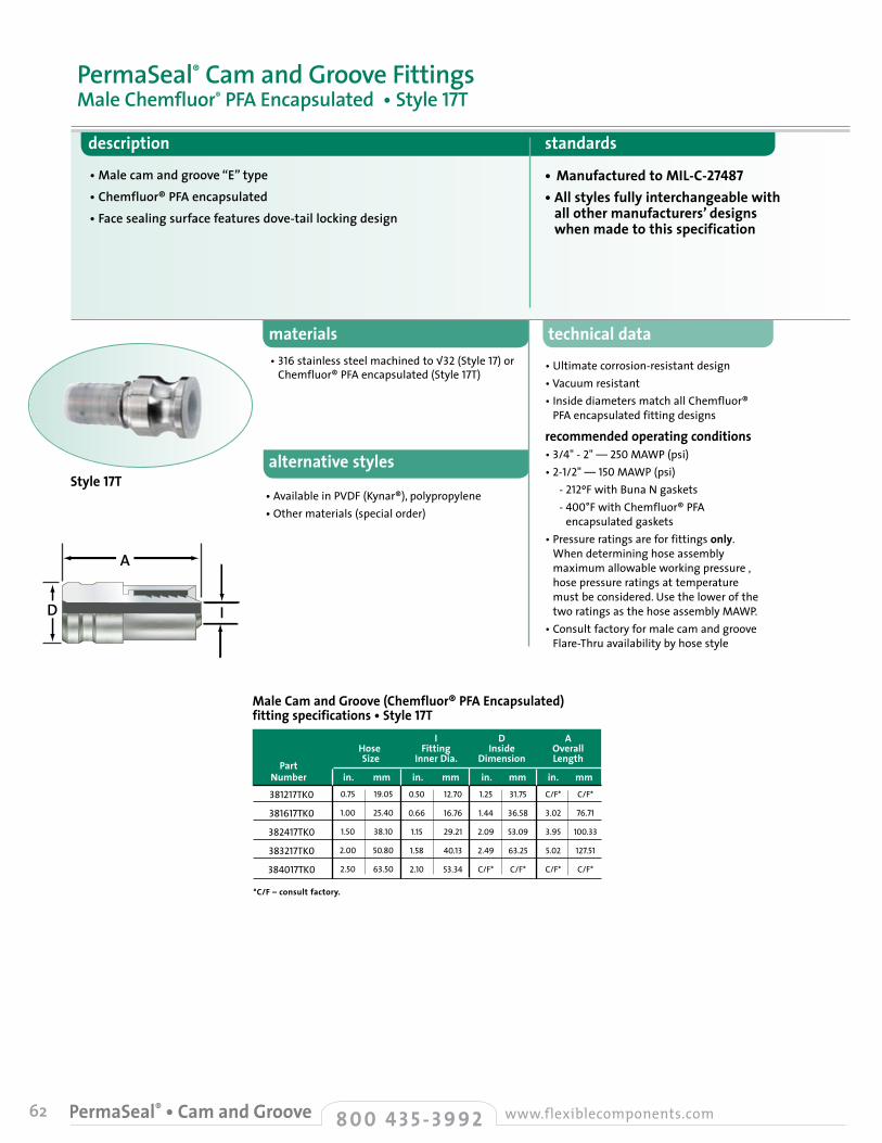
62 8 0 0 4 3 5 - 3 9 9 2 www.flexiblecomponents.comPermaSeal® • Cam and Groove
alternative styles
• Available in PVDF (Kynar®), polypropylene • Other materials (special order)
technical data
• Ultimate corrosion-resistant design• Vacuum resistant• Inside diameters match all Chemfluor®
PFA encapsulated fitting designs
recommended operating conditions• 3/4"-2" — 250 MAWP (psi)• 2-1/2"—150 MAWP (psi) - 212ºF with Buna N gaskets - 400°F with Chemfluor® PFA
encapsulated gaskets• Pressure ratings are for fittings only.
When determining hose assembly maximum allowable working pressure , hose pressure ratings at temperature must be considered. Use the lower of the two ratings as the hose assembly MAWP.
• Consult factory for male cam and groove Flare-Thru availability by hose style
materials
description standards
• Male cam and groove “E” type • Chemfluor® PFA encapsulated• Face sealing surface features dove-tail locking design
• Manufactured to MIL-C-27487• All styles fully interchangeable with
all other manufacturers’ designs when made to this specification
• 316 stainless steel machined to √32 (Style 17) or Chemfluor® PFA encapsulated (Style 17T)
PermaSeal® Cam and Groove FittingsMale Chemfluor® PFA Encapsulated • Style 17T
I D A Hose Fitting Inside Overall
Part Size Inner Dia. Dimension Length
Number in. mm in. mm in. mm in. mm
*C/F – consult factory.
0.75
1.00
1.50
2.00
2.50
19.05
25.40
38.10
50.80
63.50
0.50
0.66
1.15
1.58
2.10
12.70
16.76
29.21
40.13
53.34
1.25
1.44
2.09
2.49
C/F*
31.75
36.58
53.09
63.25
C/F*
381217TK0
381617TK0
382417TK0
383217TK0
384017TK0
Male Cam and Groove (Chemfluor® PFA Encapsulated) fitting specifications • Style 17T
C/F*
3.02
3.95
5.02
C/F*
C/F*
76.71
100.33
127.51
C/F*
D
A
I
Style 17T
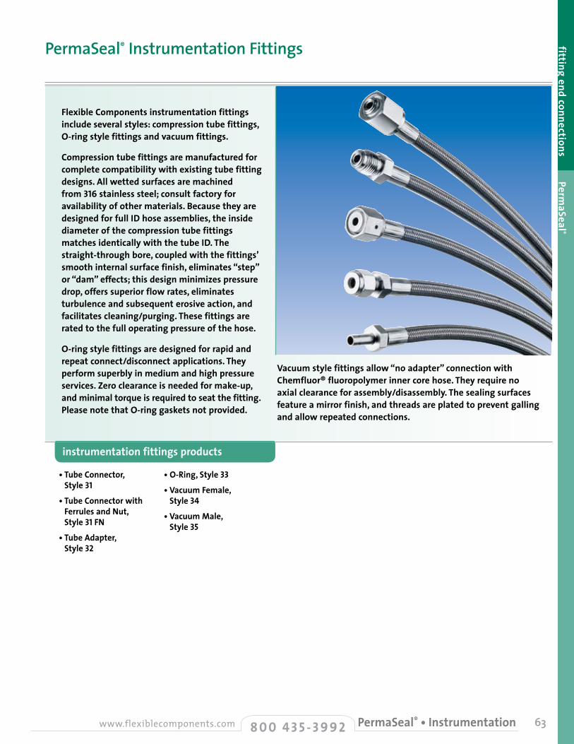
63
fitting end connections PermaSeal ®
• Tube Connector, Style 31
• Tube Connector with Ferrules and Nut, Style 31 FN
• Tube Adapter, Style 32
• O-Ring, Style 33
• Vacuum Female, Style 34
• Vacuum Male, Style 35
instrumentation fittings products
Flexible Components instrumentation fittings include several styles: compression tube fittings, O-ring style fittings and vacuum fittings.
Compression tube fittings are manufactured for complete compatibility with existing tube fitting designs. All wetted surfaces are machined from 316 stainless steel; consult factory for availability of other materials. Because they are designed for full ID hose assemblies, the inside diameter of the compression tube fittings matches identically with the tube ID. The straight-through bore, coupled with the fittings’ smooth internal surface finish, eliminates “step” or “dam” effects; this design minimizes pressure drop, offers superior flow rates, eliminates turbulence and subsequent erosive action, and facilitates cleaning/purging. These fittings are rated to the full operating pressure of the hose.
O-ring style fittings are designed for rapid and repeat connect/disconnect applications. They perform superbly in medium and high pressure services. Zero clearance is needed for make-up, and minimal torque is required to seat the fitting. Please note that O-ring gaskets not provided.
Vacuum style fittings allow “no adapter” connection with Chemfluor® fluoropolymer inner core hose. They require no axial clearance for assembly/disassembly. The sealing surfaces feature a mirror finish, and threads are plated to prevent galling and allow repeated connections.
PermaSeal® Instrumentation Fittings
8 0 0 4 3 5 - 3 9 9 2www.flexiblecomponents.com PermaSeal® • Instrumentation

I
TH
A
64 8 0 0 4 3 5 - 3 9 9 2 www.flexiblecomponents.comPermaSeal® • Instrumentation
description standards
• Manufactured for complete compatibility with existing tube fitting designs
• Straight-through bore eliminates “step” or “dam” effects
• To industry standards
materials technical data• Designed for full ID hose assemblies - When the fitting stem is inserted
into Chemfluor® fluoropolymer tube, resulting inside diameter matches identically with tube ID
• Straight-through bore, coupled with smooth internal surface finish:
- Minimizes pressure drop - Offers superior flow rates - Eliminates turbulence and subsequent
erosive action - Facilitates cleaning/purging - Rated to full operating pressure of
hose
• Furnished without ferrule(s) and nut to facilitate usage with existing inventories
• All wetted surfaces machined from 316stainless steel
- Consult factory for availability of other materials
PermaSeal® Instrumentation FittingsTube Connector •Style 31
I H A T Hose Inner Hex Overall Thread
Part Size Diameter Size Length
Number in. mm in. mm in. mm in. mm in. 0.25
0.38
0.50
0.75
1.00
6.35
9.53
12.70
19.05
25.40
0.19
0.28
0.38
0.65
0.87
4.83
7.11
9.53
16.51
22.10
0.56
0.68
0.88
1.06
1.37
14.22
17.27
22.23
26.92
34.80
160431SK0
160631SK0
160831SK0
381231SK0
381631SK0
Tube Connector fitting specifications • Style 31
1.44
1.70
1.95
2.50
2.61
36.58
43.18
49.40
63.50
66.24
7/16–20
5/8–20
3/4–20
1–20
1-1/2–20
alternative styles
• Jump sizes available
Style 31
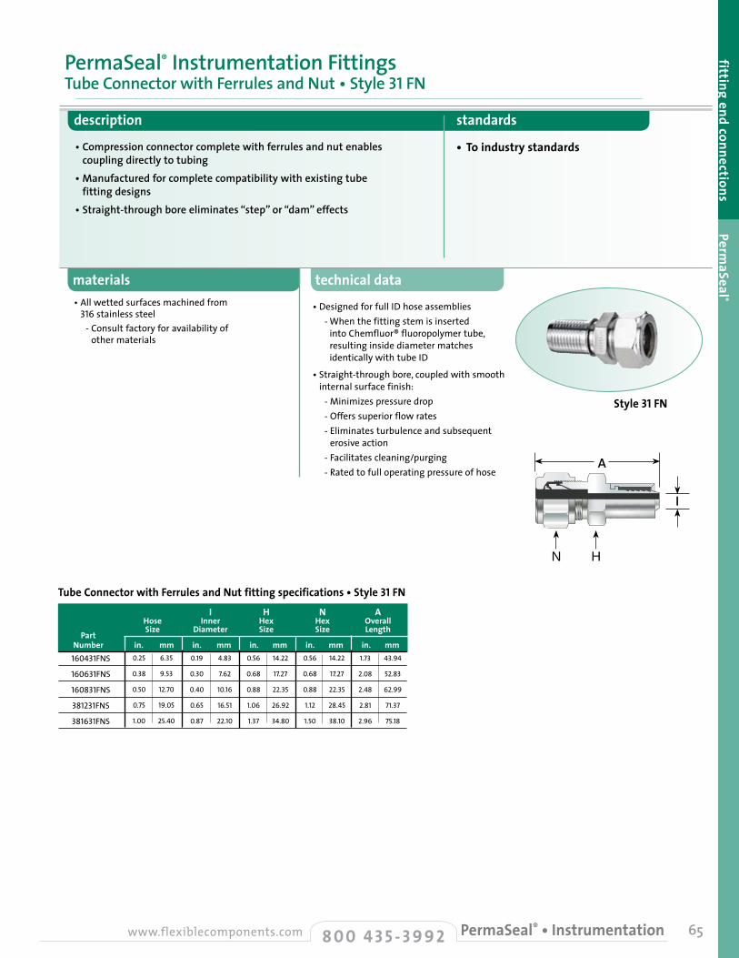
A
H (Hex Size)N (Hex Size)
technical data
• Designed for full ID hose assemblies - When the fitting stem is inserted
into Chemfluor® fluoropolymer tube, resulting inside diameter matches identically with tube ID
• Straight-through bore, coupled with smooth internal surface finish:
- Minimizes pressure drop - Offers superior flow rates - Eliminates turbulence and subsequent
erosive action - Facilitates cleaning/purging - Rated to full operating pressure of hose
65
materials
description standards
• Compression connector complete with ferrules and nut enables coupling directly to tubing
• Manufactured for complete compatibility with existing tube fitting designs
• Straight-through bore eliminates “step” or “dam” effects
• To industry standards
• All wetted surfaces machined from 316 stainless steel
- Consult factory for availability of other materials
PermaSeal® Instrumentation FittingsTube Connector with Ferrules and Nut • Style 31 FN
fitting end connections PermaSeal ®
I H N A Hose Inner Hex Hex Overall
Part Size Diameter Size Size Length
Number in. mm in. mm in. mm in. mm in. mm0.25
0.38
0.50
0.75
1.00
6.35
9.53
12.70
19.05
25.40
0.19
0.30
0.40
0.65
0.87
4.83
7.62
10.16
16.51
22.10
0.56
0.68
0.88
1.06
1.37
14.22
17.27
22.35
26.92
34.80
160431FNS
160631FNS
160831FNS
381231FNS
381631FNS
Tube Connector with Ferrules and Nut fitting specifications • Style 31 FN
0.56
0.68
0.88
1.12
1.50
14.22
17.27
22.35
28.45
38.10
1.73
2.08
2.48
2.81
2.96
43.94
52.83
62.99
71.37
75.18
A
N H
8 0 0 4 3 5 - 3 9 9 2www.flexiblecomponents.com PermaSeal® • Instrumentation
I
A
Style 31 FN

66 8 0 0 4 3 5 - 3 9 9 2 www.flexiblecomponents.comPermaSeal® • Instrumentation
description standards
• Readily accommodates other styles of fitting adapter connection• Manufactured for complete compatibility with existing
tube fitting designs• Straight-through bore eliminates “step” or “dam” effects
• To industry standards
materials technical data• Designed for full ID hose assemblies - When the fitting stem is inserted
into Chemfluor® fluoropolymer tube, resulting inside diameter matches identically with tube ID
• Straight-through bore, coupled with smooth internal surface finish:
- Minimizes pressure drop - Offers superior flow rates - Eliminates turbulence and subsequent
erosive action - Facilitates cleaning/purging - Rated to full operating pressure
of hose
• When utilizing Flexible Components hoses with Style 32 fittings, it is recommended that ferrules be pre-swaged to the tubing to eliminate potential torquing of the hose
• All wetted surfaces machined from 316 stainless steel
- Consult factory for availability of other materials
PermaSeal® Instrumentation FittingsTube Adapter • Style 32
I H A Hose Inner Hex Tube End Overall
Part Size Diameter Size OD Nominal Length
Number in. mm in. mm in. mm in. mm in. mm0.25
0.38
0.50
0.75
1.00
6.35
9.53
12.70
19.05
25.40
0.19
0.30
0.40
0.65
0.87
4.83
7.62
10.16
16.51
22.10
0.56
0.68
0.88
1.06
1.37
14.22
17.27
22.35
26.92
34.80
160432FNS
160632FNS
160832FNS
381232FNS
381632FNS
Tube Adapter fitting specifications • Style 32
0.25
0.38
0.50
0.75
1.00
6.35
9.65
12.70
19.05
25.40
1.70
2.00
2.53
3.04
3.28
43.18
50.80
64.26
77.22
83.31
A
H (Hex Size)
A
H
I
A
Style 32

technical data• Zero clearance needed for make-up
• Requires minimal torque to seat
• Performs superbly in medium and high pressure services
• Prevents torquing of hose during hook-up
• A number of manufacturers offer O-ring style connections; compare thread sizes of Style 33 fittings before attempting interchange
• Temperature ratings of O-ring assemblies are dependent on the temperature rating of the O-ring gasket material
- O-ring gaskets not provided
67
materials
description standards
• Designed for rapid and repeat connect/disconnect applications • To industry standards
• 316stainless steel
PermaSeal® Instrumentation FittingsO-Ring • Style 33
fitting end connections PermaSeal ®
I H A T Hose Inner Hex Overall Thread
Part Size Diameter Size Length
Number in. mm in. mm in. mm in. mm in. 0.25
0.38
0.50
0.75
1.00
6.35
9.53
12.70
19.05
25.40
0.19
0.30
0.40
0.65
0.87
4.83
7.62
10.16
16.51
22.10
0.68
1.00
1.12
1.50
1.75
17.27
25.40
28.45
38.10
44.45
160433SKN
160633SKN
160833SKN
381233SKN
381633SKN
O-Ring fitting specifications • Style 33
1.83
1.95
1.95
2.19
2.50
46.48
49.53
49.53
55.63
63.50
9/16–18
7/8–14
1–14
1-1/4–18
1-1/2–20
A
H (Hex Size)
T (Thread Size)T
8 0 0 4 3 5 - 3 9 9 2www.flexiblecomponents.com PermaSeal® • Instrumentation
H
I
A
Style 33
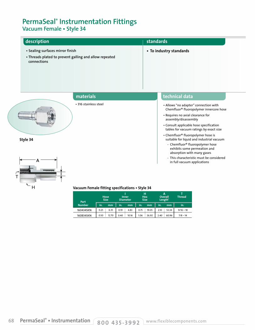
68 8 0 0 4 3 5 - 3 9 9 2 www.flexiblecomponents.comPermaSeal® • Instrumentation
description standards
• Sealing surfaces mirror finish• Threads plated to prevent galling and allow repeated
connections
• To industry standards
materials technical data• Allows “no adapter” connection with
Chemfluor® fluoropolymer innercore hose
• Requires no axial clearance for assembly/disassembly
• Consult applicable hose specification tables for vacuum ratings by exact size
• Chemfluor® fluoropolymer hose is suitable for liquid and industrial vacuum
- Chemfluor® fluoropolymer hose exhibits some permeation and absorption with many gases
- This characteristic must be considered in full vacuum applications
• 316stainless steel
PermaSeal® Instrumentation FittingsVacuum Female • Style 34
I H A T Hose Inner Hex Overall Thread
Part Size Diameter Size Length’
Number in. mm in. mm in. mm in. mm in. 0.25
0.50
6.35
12.70
0.19
0.40
4.83
10.16
0.75
1.06
19.05
26.92
160434SKN
160834SKN
Vacuum Female fitting specifications • Style 34
2.10
2.40
53.34
60.96
9/16–18
7/8–14
A
H (Hex Size)
T (Thread Size)TI
A
H
Style 34

technical data
• Allows “no adapter” connection with Chemfluor® fluoropolymer innercore hose
• Requires no axial clearance for assembly/disassembly
• Consult applicable hose specification tables for vacuum ratings by exact size
• Chemfluor® fluoropolymer hose is suitable for liquid and industrial vacuum
- Chemfluor® fluoropolymer hose exhibits some permeation and absorption with many gases
- This characteristic must be considered in full vacuum applications
69
materials
description standards
• Sealing surfaces mirror finish• Threads plated to prevent galling and allow repeated connections
• To industry standards
• 316stainless steel
PermaSeal® Instrumentation FittingsVacuum Male • Style 35
fitting end connections PermaSeal ®
T (Thread Size)
A
H (Hex Size)
I H A T Hose Inner Hex Overall Thread
Part Size Diameter Size Length
Number in. mm in. mm in. mm in. mm in. 0.25
0.50
6.35
12.70
0.19
0.40
4.83
10.16
0.68
0.94
17.27
23.88
160435SKN
160835SKN
Vacuum Male fitting specifications • Style 35
1.61
1.80
40.89
45.72
9/16–18
7/8–14
TH
8 0 0 4 3 5 - 3 9 9 2www.flexiblecomponents.com PermaSeal® • Instrumentation
I
A
Style 35

70 8 0 0 4 3 5 - 3 9 9 2 www.flexiblecomponents.comPermaSeal® • Miscellaneous
description standards
• Style 01 Schedule 40 (or alternative Schedule 10 or Schedule 80) butt weld fittings allow fabrication flexibility; when special non-standard connections must be made in lieu of standard Flexible Components styles, butt weld fittings provide a connection solution
• Schedule 40• Other pipe schedules available by special order;
consult factory
materials technical data• Alternative fitting styles may be welded
to butt weld pipe (or tube Style 41— see page 56) prior to PermaSeal attachment to finished hose assemblies
• Available for welding to existing systems when proper “heat sink” methods are employed to prevent hose liner damage
• 316stainless steel• Consult factory for availability of
alternative materials
PermaSeal® Miscellaneous FittingsButt Weld/Pipe Size • Style 01
B
AButt Weld /Pipe Size fitting specifications • Style 01 A B C Hose Butt Weld Overall Butt Weld
Part Size Outer Dia. Length Length
Number in. mm in. mm in. mm in. mm 0.50
0.75
1.00
1.25
1.50
2.00
2.50
3.00
4.00
12.70
19.05
25.40
31.75
38.10
50.80
63.50
76.20
101.60
0.84
1.05
1.31
1.66
1.90
2.38
2.88
3.50
4.50
21.34
26.67
33.27
42.16
48.26
60.33
73.03
88.90
114.30
1.92
2.23
2.67
3.26
3.36
4.30
3.71
4.16
4.28
48.64
56.52
67.82
82.80
85.32
109.09
94.23
105.66
108.79
0.50
0.75
0.75
0.75
0.75
1.00
0.50
0.60
0.25
12.70
19.05
19.05
19.05
19.05
25.40
12.70
15.24
6.35
160801SK0
381201SK0
381601SK0
382001SK0
382401SK0
383201SK0
384001SK0
384801SK0
386401SK0
A
B
C
Style 01

71
fitting end connections pipe interface adapters
types of pipe interface adapters
Chemfluor® FEP Fluoropolymer Lined
Chemfluor® PFA Fluoropolymer Encapsulated
Pure-Fit® Stainless Steel
8 0 0 4 3 5 - 3 9 9 2www.flexiblecomponents.com Pipe Interface Adapters
Flexible Components manu-factures an extensive array of transitional pieces designed to interface with Saint-Gobain hose assemblies and existing pipe and tubing systems. These adapters are offered in several materials:
• Stainless steel lined with Chemfluor® FEP fluoropolymer
• Chemfluor® PFA encapsulated stainless steel
• Stainless steel
• Exotic alloys
Adapters• Highest quality material —
316L stainless steel, compared to the 304 stainless steel used in many competing products.
• Wide range of sizes — 3/4" - 4" ID.• Common fitting styles — sanitary
clamp (including mini) by MNPT or FNPT standard.
• Smooth, highly finished ID — 12 - 15 Ra surface finish standard.
• Easy installation — Hex or “wrenching” flats eliminate pipe wrench surface marring.
• Reduced hose assembly connection labor — Sanitary clamp style connections speed up the process thanks to easy-to-use gasket and clamp Saint-Gobain PermaSeal® or Flare-Thru configured hose assemblies.
• Entrapment problems minimized — Smooth machined ID reduces surface roughness often found on “as cast” adapters.
• Traceability — Material Certifications available with PIN stamped heat trace numbers.
• Leak paths eliminated — Large range of multiple “step” by size transitions eliminate common practice of stacked single-step reducers.
• Specials available — Connection styles other than sanitary by NPT available to meet your unique application requirements.
• Alternative materials — Polypropylene and PVDF (Kynar®) available.
Sanitary End Caps• Highest quality material —
316L stainless steel standard.• Sizes — 3/4" - 4" ID.• Material Certification available.
features and benefits
Flexible Components Pipe Interface Adapters
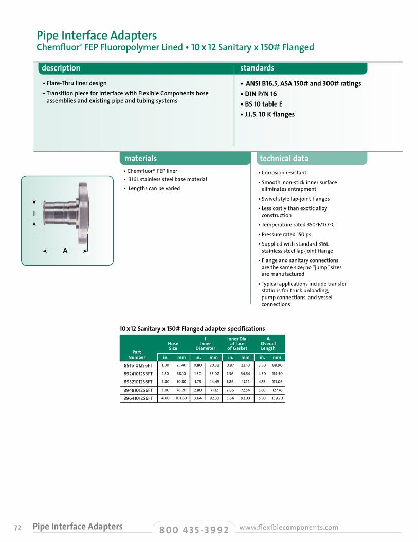
72 8 0 0 4 3 5 - 3 9 9 2 www.flexiblecomponents.comPipe Interface Adapters
description standards
• Flare-Thru liner design• Transition piece for interface with Flexible Components hose
assemblies and existing pipe and tubing systems
• ANSI B16.5, ASA 150# and 300# ratings• DIN P/N 16 • BS 10 table E• J.I.S. 10 K flanges
materials technical data• Corrosion resistant
• Smooth, non-stick inner surface eliminates entrapment
• Swivel style lap-joint flanges
• Less costly than exotic alloy construction
• Temperature rated 350ºF/177ºC
• Pressure rated 150 psi
• Supplied with standard 316L stainless steel lap-joint flange
• Flange and sanitary connections are the same size; no “jump” sizes are manufactured
• Typical applications include transfer stations for truck unloading, pump connections, and vessel connections
• Chemfluor® FEP liner• 316Lstainless steel base material
• Lengths can be varied
Pipe Interface AdaptersChemfluor® FEP Fluoropolymer Lined • 10 x 12 Sanitary x 150# Flanged
I Inner Dia. A Hose Inner at face Overall
Part Size Diameter of Gasket Length
Number in. mm in. mm in. mm in. mm1.00
1.50
2.00
3.00
4.00
25.40
38.10
50.80
76.20
101.60
0.80
1.30
1.75
2.80
3.64
20.32
33.02
44.45
71.12
92.33
0.87
1.36
1.86
2.86
3.64
22.10
34.54
47.14
72.54
92.33
89161012S6FT
89241012S6FT
89321012S6FT
89481012S6FT
89641012S6FT
10 x 12 Sanitary x 150# Flanged adapter specifications
3.50
4.50
4.53
5.03
5.50
88.90
114.30
115.06
127.76
139.70
A
I
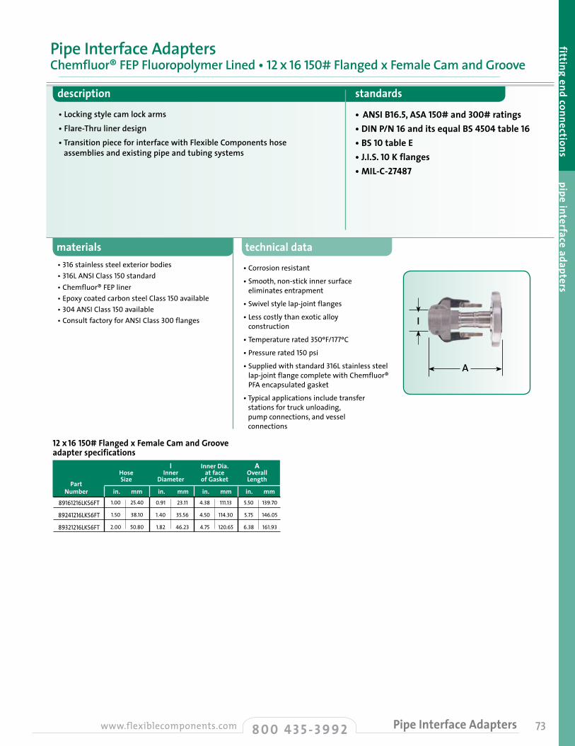
technical data
• Corrosion resistant
• Smooth, non-stick inner surface eliminates entrapment
• Swivel style lap-joint flanges
• Less costly than exotic alloy construction
• Temperature rated 350ºF/177ºC
• Pressure rated 150 psi
• Supplied with standard 316L stainless steel lap-joint flange complete with Chemfluor® PFA encapsulated gasket
• Typical applications include transfer stations for truck unloading, pump connections, and vessel connections
73
materials
description standards
• Locking style cam lock arms• Flare-Thru liner design• Transition piece for interface with Flexible Components hose
assemblies and existing pipe and tubing systems
• ANSI B16.5, ASA 150# and 300# ratings• DIN P/N 16 and its equal BS 4504 table 16 • BS 10 table E• J.I.S. 10 K flanges• MIL-C-27487
• 316stainless steel exterior bodies• 316LANSI Class 150 standard• Chemfluor® FEP liner• Epoxy coated carbon steel Class150 available• 304ANSIClass150available• Consult factory for ANSI Class 300 flanges
Pipe Interface AdaptersChemfluor® FEP Fluoropolymer Lined • 12 x 16 150# Flanged x Female Cam and Groove
fitting end connections pipe interface adapters
I Inner Dia. A Hose Inner at face Overall
Part Size Diameter of Gasket Length
Number in. mm in. mm in. mm in. mm1.00
1.50
2.00
25.40
38.10
50.80
0.91
1.40
1.82
23.11
35.56
46.23
4.38
4.50
4.75
111.13
114.30
120.65
89161216LKS6FT
89241216LKS6FT
89321216LKS6FT
12 x 16 150# Flanged x Female Cam and Groove adapter specifications
5.50
5.75
6.38
139.70
146.05
161.93
8 0 0 4 3 5 - 3 9 9 2www.flexiblecomponents.com Pipe Interface Adapters
A
I
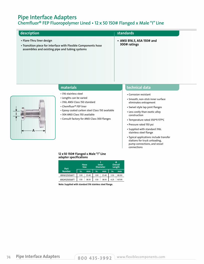
74 8 0 0 4 3 5 - 3 9 9 2 www.flexiblecomponents.comPipe Interface Adapters
description standards
• Flare-Thru liner design• Transition piece for interface with Flexible Components hose
assemblies and existing pipe and tubing systems
• ANSI B16.5, ASA 150# and 300# ratings
materials technical data• Corrosion resistant
• Smooth, non-stick inner surface eliminates entrapment
• Swivel style lap-joint flanges
• Less costly than exotic alloy construction
• Temperature rated 350ºF/177ºC
• Pressure rated 150 psi
• Supplied with standard 316L stainless steel flange
• Typical applications include transfer stations for truck unloading, pump connections, and vessel connections
• 316stainless steel• Lengths can be varied• 316LANSI Class 150 standard• Chemfluor® FEP liner• Epoxy coated carbon steel Class150 available• 304ANSIClass150available• Consult factory for ANSI Class 300 flanges
Pipe Interface AdaptersChemfluor® FEP Fluoropolymer Lined • 12 x 50 150# Flanged x Male “I” Line
I A Hose Inner Overall
Part Size Diameter Length
Number in. mm in. mm in. mm
Note: Supplied with standard 316 stainless steel flange.
1.00
1.50
25.40
38.10
1.00
1.50
25.40
38.10
3.50
4.25
88.90
107.95
89161250S6FT
89241250S6FT
12 x 50 150# Flanged x Male “I” Line adapter specifications
A
I
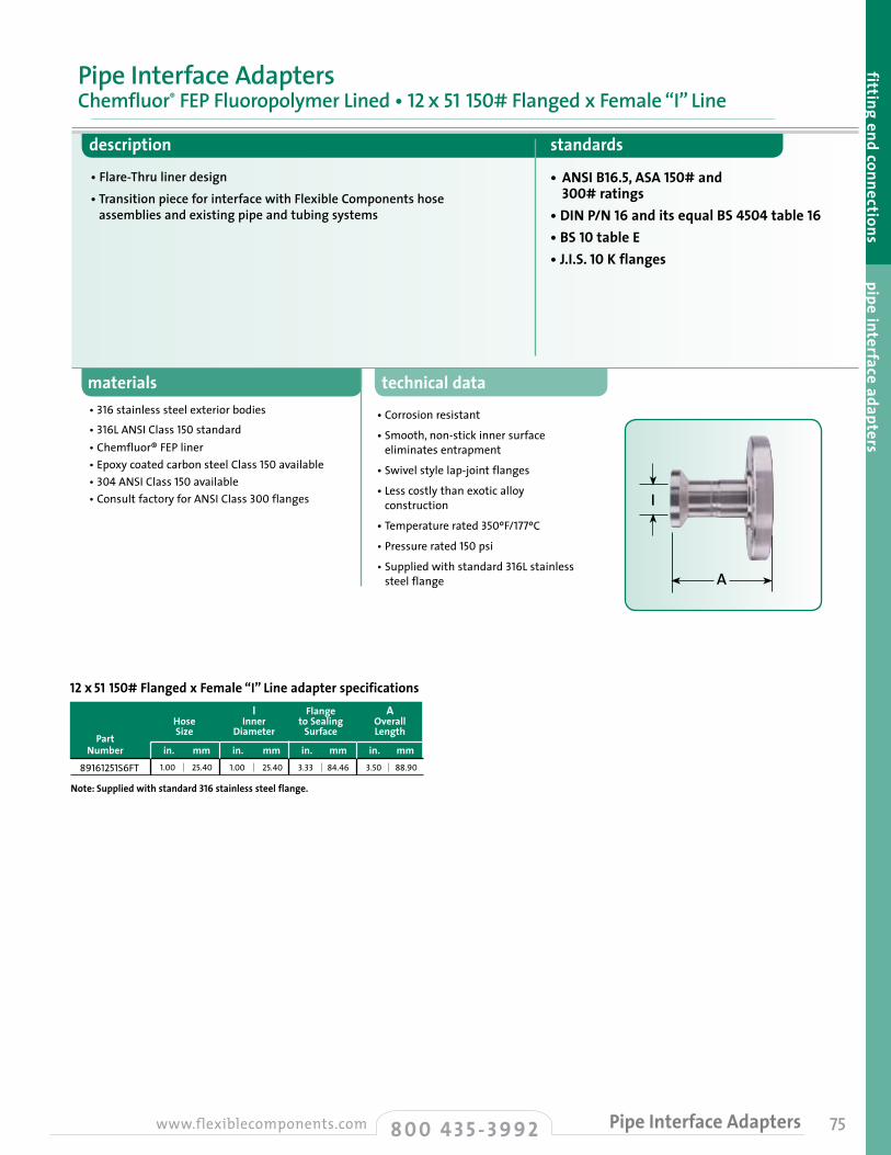
technical data
• Corrosion resistant
• Smooth, non-stick inner surface eliminates entrapment
• Swivel style lap-joint flanges
• Less costly than exotic alloy construction
• Temperature rated 350ºF/177ºC
• Pressure rated 150 psi
• Supplied with standard 316L stainless steel flange
75
materials
description standards
• Flare-Thru liner design• Transition piece for interface with Flexible Components hose
assemblies and existing pipe and tubing systems
• ANSI B16.5, ASA 150# and 300# ratings
• DIN P/N 16 and its equal BS 4504 table 16 • BS 10 table E• J.I.S. 10 K flanges
• 316stainless steel exterior bodies
• 316LANSI Class 150 standard• Chemfluor® FEP liner• Epoxy coated carbon steel Class150 available• 304ANSIClass150available• Consult factory for ANSI Class 300 flanges
Pipe Interface AdaptersChemfluor® FEP Fluoropolymer Lined • 12 x 51 150# Flanged x Female “I” Line
fitting end connections pipe interface adapters
I Flange A Hose Inner to Sealing Overall
Part Size Diameter Surface Length
Number in. mm in. mm in. mm in. mm
Note: Supplied with standard 316 stainless steel flange.
1.00 25.40 1.00 25.40 3.33 84.4689161251S6FT
12 x 51 150# Flanged x Female “I” Line adapter specifications
3.50 88.90
8 0 0 4 3 5 - 3 9 9 2www.flexiblecomponents.com Pipe Interface Adapters
A
I

76 8 0 0 4 3 5 - 3 9 9 2 www.flexiblecomponents.comPipe Interface Adapters
description standards
• Flange by cam and groove adapter; flange is 150# lap-joint (swivel) style
• Transition piece for interface with Flexible Components hose assemblies and existing pipe and tubing systems
• Chemfluor® PFA liner “locked in” to stainless steel body
• ANSI B16.5, ASA 150# and 300# ratings
• DIN P/N 16 and its equal BS 4504 table 16• BS 10 table E• J.I.S. 10 K flanges
materials technical data• Corrosion resistant• All 316 stainless steel exterior bodies• Smooth, non-stick inner surface
eliminates entrapment• Less costly than exotic alloy construction• Vacuum rated
temperature rating• -100ºFto450ºF•-73ºCto232ºC
pressure rating• Pressure rated to 150# lap-joint
flange rating or mating female cam and groove/gasket rating; see page60
•Consult factory for 300# flanges
• Chemfluor® PFA encapsulated with 316 stainless steel base material
•Standard flange: epoxy-coated carbon steel
•150#,304and316stainless steel, and300#flanges optional
Pipe Interface AdaptersChemfluor® PFA Fluoropolymer Encapsulated • Male Cam and Groove x 150# Flanged • Style 18T
Style 18T
A
I
Male Cam and Groove x 150# Flanged adapter specifications • Style 18T I A Hose Inner Outer Overall
Part Size Diameter Diameter Length
Number in. mm in. mm in. mm in. mm
• For adapter with epoxy-coated carbon steel flange, replace “00” with “C0” in part number.
• For adapter with 304 stainless steel flange, replace “00” with “S4” in part number.
• For adapter with 316L stainless steel flange, replace “00” with “S6” in part number.
0.75
1.00
1.50
2.00
3.00
19.05
25.40
38.10
50.80
76.20
0.70
0.83
1.19
1.75
2.86
17.78
20.96
30.23
44.45
72.64
1.25
1.44
2.15
2.49
3.60
31.75
36.58
54.61
63.25
91.44
3.35
3.75
4.13
4.50
5.13
85.09
95.25
104.78
114.30
130.18
381218T00
381618T00
382418T00
383218T00
384818T00
! Important:
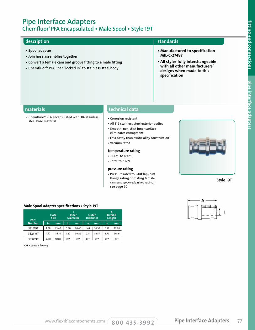
technical data
• Corrosion resistant• All 316 stainless steel exterior bodies• Smooth, non-stick inner surface
eliminates entrapment• Less costly than exotic alloy construction• Vacuum rated
temperature rating• -100ºFto450ºF•-73ºCto232ºC
pressure rating• Pressure rated to 150# lap-joint
flange rating or mating female cam and groove/gasket rating; see page 60
77
materials
description standards
• Spool adapter• Join hose assemblies together• Convert a female cam and groove fitting to a male fitting• Chemfluor® PFA liner “locked in” to stainless steel body
• Manufactured to specification MIL-C-27487
• All styles fully interchangeable with all other manufacturers’ designs when made to this specification
• Chemfluor® PFA encapsulated with 316 stainless steel base material
Pipe Interface AdaptersChemfluor® PFA Encapsulated • Male Spool • Style 19T
fitting end connections pipe interface adapters
Style 19T
Male Spool adapter specifications • Style 19T I A Hose Inner Outer Overall
Part Size Diameter Diameter Length
Number in. mm in. mm in. mm in. mm
*C/F – consult factory.
1.00
1.50
2.00
25.40
38.10
50.80
0.80
1.22
CF*
20.40
30.86
CF*
1.44
2.11
CF*
36.50
53.57
CF*
3.18
3.79
CF*
80.80
96.16
CF*
381619T
382419T
383219T
A
I
8 0 0 4 3 5 - 3 9 9 2www.flexiblecomponents.com Pipe Interface Adapters
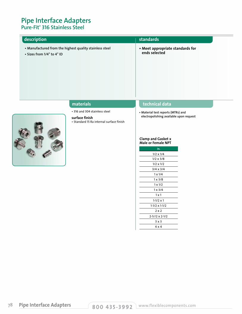
78 8 0 0 4 3 5 - 3 9 9 2 www.flexiblecomponents.comPipe Interface Adapters
description standards
• Manufactured from the highest quality stainless steel• Sizes from 1/4" to 4" ID
• Meet appropriate standards for ends selected
materials technical data• Material test reports (MTRs) and
electropolishing available upon request• 316 and 304 stainless steel
surface finish • Standard 15 Ra internal surface finish
Pipe Interface AdaptersPure-Fit® 316 Stainless Steel
Clamp and Gasket x Male or Female NPT in.
1/2x1/41/2x3/81/2x1/23/4x3/41x1/41x3/81x1/21x3/41x1
1-1/2x11-1/2x1-1/2
2x2
2-1//2x2-1/23x34x4
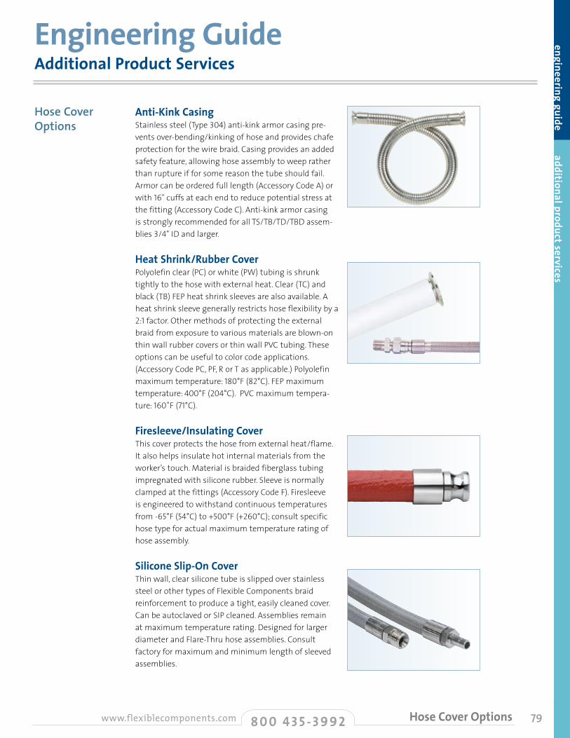
79
engineering guide additional product services
Anti-Kink CasingStainless steel (Type 304) anti-kink armor casing pre-vents over-bending/kinking of hose and provides chafe protection for the wire braid. Casing provides an added safety feature, allowing hose assembly to weep rather than rupture if for some reason the tube should fail. Armor can be ordered full length (Accessory Code A) or with 16" cuffs at each end to reduce potential stress at the fitting (Accessory Code C). Anti-kink armor casing is strongly recommended for all TS/TB/TD/TBD assem-blies 3/4" ID and larger.
Heat Shrink/Rubber CoverPolyolefin clear (PC) or white (PW) tubing is shrunk tightly to the hose with external heat. Clear (TC) and black (TB) FEP heat shrink sleeves are also available. A heat shrink sleeve generally restricts hose flexibility by a 2:1 factor. Other methods of protecting the external braid from exposure to various materials are blown-on thin wall rubber covers or thin wall PVC tubing. These options can be useful to color code applications. (Accessory Code PC, PF, R or T as applicable.) Polyolefin maximum temperature: 180°F (82°C). FEP maximum temperature: 400°F (204°C). PVC maximum tempera-ture: 160˚F (71°C).
Firesleeve/Insulating CoverThis cover protects the hose from external heat/flame. It also helps insulate hot internal materials from the worker’s touch. Material is braided fiberglass tubing impregnated with silicone rubber. Sleeve is normally clamped at the fittings (Accessory Code F). Firesleeve is engineered to withstand continuous temperatures from -65°F (54°C) to +500°F (+260°C); consult specific hose type for actual maximum temperature rating of hose assembly.
Silicone Slip-On CoverThin wall, clear silicone tube is slipped over stainless steel or other types of Flexible Components braid reinforcement to produce a tight, easily cleaned cover. Can be autoclaved or SIP cleaned. Assemblies remain at maximum temperature rating. Designed for larger diameter and Flare-Thru hose assemblies. Consult factory for maximum and minimum length of sleeved assemblies.
Additional Product ServicesEngineering Guide
Hose Cover Options
8 0 0 4 3 5 - 3 9 9 2www.flexiblecomponents.com Hose Cover Options

80 8 0 0 4 3 5 - 3 9 9 2 www.flexiblecomponents.comHose Cover/Hose Options
Various Covers and Braid Material Process segregation sometimes requires color hose assemblies to help prevent mismatching. Heat shrink sleeves also enable the hose exterior to be cleaned more easily and prevent material from sticking in the braid interstices. Sometimes a non-metallic braid is required. The blue hose shown near right has a polypropylene braid; Kynar® braid is black.
Color Coding OptionsColors may be special ordered for TLCT/SFTL, TLCTCO and CTLCT rubber covered hose. Consult factory for minimum order requirements.
Custom Hose TaggingMost Flexible Components hoses can be tagged with a stainless steel Band-it® clamp. We can tag hoses 1/2" ID and larger*. Customers can specify information; otherwise the following default information applies: • Maximum allowable working pressure • Date of manufacture • Flexible Components name or logo
*1/4" ID and 3/8" ID hoses are tagged with a roll stamped aluminum ring.
Stainless Steel Tag SpecificationsDimensions: • .75" x 1.94" x 0.010" thick • 0.625" x 1.44" printing area • Maximum characters —3 lines of 15 characters • Attachment— one 1/4" wide Band-it® clamp
Large Stainless Steel Tag SpecificationsDimensions: • 1.5" x 2.5" x 0.015" thick • 0.94" x 1.75" printing area • Maximum characters—6 lines of 15 characters • Attachment— two 1/4" wide Band-it® clamps
Hose Identification SystemThe SANIseal™ silicone label encapsulation system allows key information such as date of manufacture, lot number, approval criteria and re-order phone number to be permanently sealed and bonded to Flexible Components hoses — with no product contact and no areas where entrapment can occur. SANIseal™ meets or exceeds FDA requirements on hose identification, is very
durable, and operates at the touch of a single button. It is compatible with the full range of Flexible Components hoses through 3" ID, including those with silicone, stainless steel and EPDM rubber covers. Lightweight SANIseal™ field fabrication equipment is available for convenient on-site use.
Special Alloy and Non-Metallic FittingsFlexible Components has manufactured many types of special alloy and non-metallic fittings to complement our standard product line (Flare-Thru, PFA encapsulated 316 stainless steel). Materials from which we have fabricated fittings include:
This is only a partial list. Please do not hesitate to contact the factory for information on unusual fitting requirements, but bear in mind that cost and delivery schedule are directly related to the size, complexity and quantity of fittings ordered.
Hose Cover Options
Hose Options
Additional Product Services
• Brass• Carbon steel • Hastelloy® B and Hastelloy® C
• Monel® • Titanium • PVC • Polypropylene
• PVDF (Kynar®) • Solid PTFE • FEP-coated stainless steel
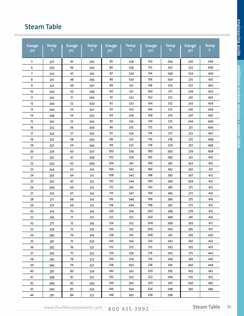
81
engineering guide additional product services • steam table
Gauge Temp Gauge Temp Gauge Temp Gauge Temp Gauge Temp psi ˚F psi ˚F psi ˚F psi ˚F psi ˚F
5
6
7
8
9
10
11
12
13
14
15
16
17
18
19
20
21
22
23
24
25
26
27
28
29
30
32
32
33
34
35
36
37
38
39
40
41
42
43
44
227
230
232
235
237
240
242
244
246
248
250
252
254
255
257
259
261
262
264
265
267
268
270
271
273
274
276
277
278
280
281
282
283
285
286
287
288
289
290
291
45
46
47
48
49
50
51
52
53
54
55
56
57
58
59
60
61
62
63
64
65
66
67
68
69
70
71
72
73
74
75
76
77
78
79
80
81
82
83
84
293
294
295
296
297
298
299
300
301
302
303
304
305
306
306
307
308
309
310
311
312
313
314
314
315
316
317
318
319
319
320
321
322
322
323
324
325
326
326
327
85
86
87
88
89
90
91
92
93
94
95
96
97
98
99
100
102
104
106
108
110
112
114
116
118
120
122
124
126
128
130
132
134
136
138
140
142
144
146
148
328
328
329
330
331
331
332
333
333
334
335
335
336
337
337
338
339
341
342
343
344
345
347
348
349
350
351
352
353
355
356
357
358
359
360
361
362
363
364
365
150
152
154
156
158
160
162
164
166
168
170
172
174
176
178
180
182
184
186
188
190
192
194
196
198
200
202
204
206
208
210
212
214
216
218
220
222
224
226
228
366
367
368
369
370
371
372
372
373
374
375
376
377
378
379
380
380
381
382
383
384
385
385
386
387
388
389
389
390
391
392
392
393
394
395
395
396
397
398
398
230
232
234
235
237
239
241
243
245
247
249
251
253
255
257
259
261
263
265
267
269
271
273
275
277
279
281
283
285
295
305
355
375
385
405
455
510
560
585
399
400
400
401
402
402
403
404
404
405
406
406
407
408
408
409
410
410
411
412
412
413
414
414
415
415
416
417
417
420
423
437
442
445
449
461
472
482
486
Steam Table
8 0 0 4 3 5 - 3 9 9 2www.flexiblecomponents.com Steam Table
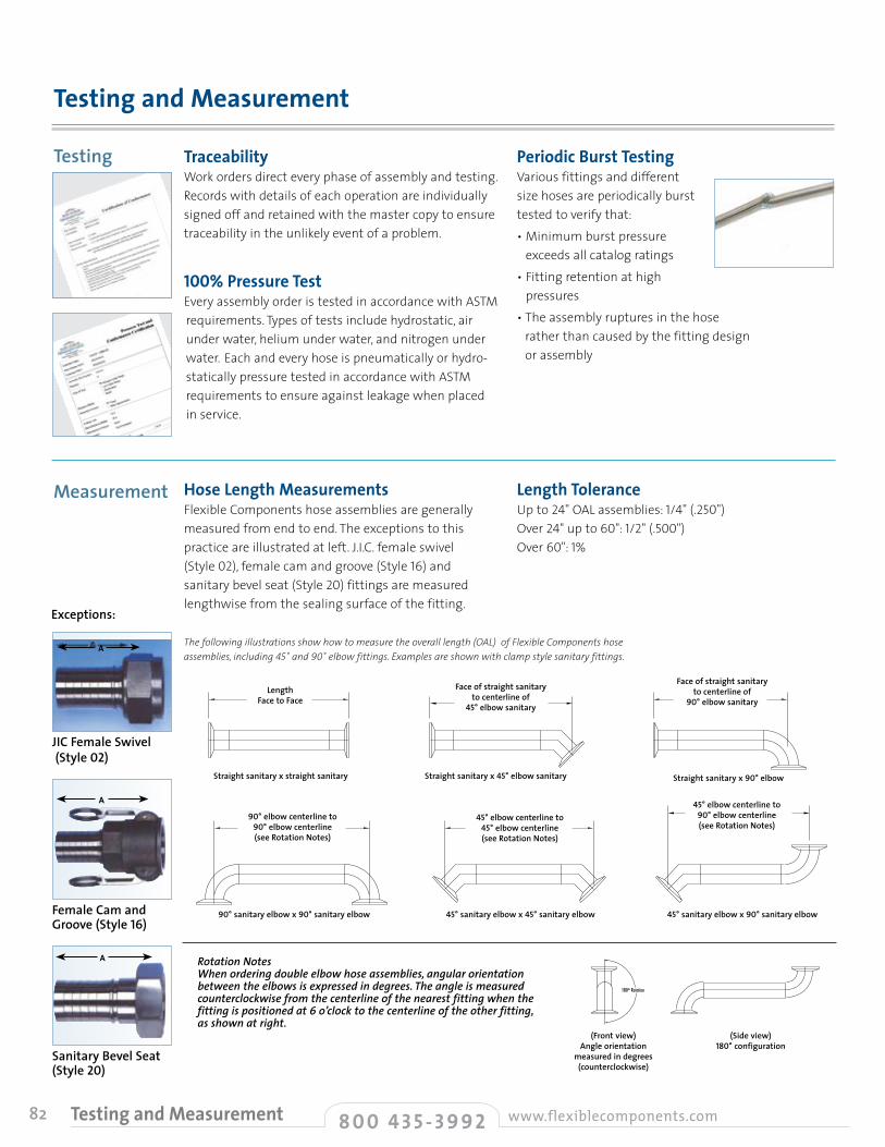
82
TraceabilityWork orders direct every phase of assembly and testing. Records with details of each operation are individually signed off and retained with the master copy to ensure traceability in the unlikely event of a problem.
100% Pressure TestEvery assembly order is tested in accordance with ASTM requirements. Types of tests include hydrostatic, air under water, helium under water, and nitrogen under water. Each and every hose is pneumatically or hydro-statically pressure tested in accordance with ASTM requirements to ensure against leakage when placed in service.
Periodic Burst TestingVarious fittings and different size hoses are periodically burst tested to verify that:• Minimum burst pressure
exceeds all catalog ratings• Fitting retention at high
pressures• The assembly ruptures in the hose
rather than caused by the fitting design or assembly
Hose Length MeasurementsFlexible Components hose assemblies are generally measured from end to end. The exceptions to this practice are illustrated at left. J.I.C. female swivel (Style 02), female cam and groove (Style 16) and sanitary bevel seat (Style 20) fittings are measured lengthwise from the sealing surface of the fitting.
Length ToleranceUp to 24" OAL assemblies: 1/4" (.250") Over 24" up to 60": 1/2" (.500") Over 60": 1%
Testing and Measurement
Testing
Measurement
(Front view) Angle orientation
measured in degrees (counterclockwise)
(Side view) 180° configuration
Rotation Notes When ordering double elbow hose assemblies, angular orientation between the elbows is expressed in degrees. The angle is measured counterclockwise from the centerline of the nearest fitting when the fitting is positioned at 6 o’clock to the centerline of the other fitting, as shown at right.
LengthFace to Face
Straight sanitary x straight sanitary Straight sanitary x 45° elbow sanitary Straight sanitary x 90° elbow
Face of straight sanitary to centerline of
45° elbow sanitary
Face of straight sanitary to centerline of
90° elbow sanitary
90° sanitary elbow x 90° sanitary elbow 45° sanitary elbow x 45° sanitary elbow 45° sanitary elbow x 90° sanitary elbow
90° elbow centerline to 90° elbow centerline (see Rotation Notes)
45° elbow centerline to 45° elbow centerline (see Rotation Notes)
45° elbow centerline to 90° elbow centerline (see Rotation Notes)
A
A
A
JIC Female Swivel (Style 02)
Female Cam and Groove (Style 16)
Sanitary Bevel Seat (Style 20)
Exceptions:
The following illustrations show how to measure the overall length (OAL) of Flexible Components hose assemblies, including 45˚ and 90˚ elbow fittings. Examples are shown with clamp style sanitary fittings.
8 0 0 4 3 5 - 3 9 9 2 www.flexiblecomponents.comTesting and Measurement

83
For Chemfluor® fluoropolymer hose assemblies, factor the live length shown below by 2.5, then add the fitting lengths to arrive at recommended OAL.
Assembly Length (Live and Overall Length)The live length and overall length of the assembly must be determined to complete the design. The live length is the flexible portion of an assembly. After the live length has been determined, the overall length is deter-mined by adding the dimensions for the end fittings.
Additional Information See page 47 for lap-joint flange data, and pages 59-62 for cam and groove recommended operating conditions.
Motion CalculationsAxial Motion: Motion that occurs when a hose is compressed along its longitudinal axis. Axial motion is only applicable in very short lengths of annular hose only. Fluoropolymer lined hose should not be subjected to axial motion.
Offset Motion: Motion that occurs when one end of the hose is deflected in a plane perpendicular to its longitudinal axis with the ends remaining parallel. In offset applications where motion is repeated, the offset should never exceed 25% of the minimum bend radius. To calculate the required live length to achieve a desired offset, use the following calculations:
Live Hose Length for Offset Motion in Metal Hose
engineering guide testing and measurem
ent • live hose length
LL = √ 6YR + Y2 LL = hose live length, inches R = min. bend radius, inches Y = offset, inches OAL = LL + fitting length + (2x nominal hose diameter)
Note: Where offset motion “Y” occurs on both sides of hose centerline, the hose live length should be based on total travel, or 2Y. The modified calculation will be:LL = √ 12YR + (2Y)2
O A L
L L
Intermittent Offset Motion Maximum Distance From Centerline 1⁄8" 1⁄4" 3⁄8" 1⁄2" 3⁄4" 1" 11⁄2" 2" 3" 4" 5" 6" 8" 10"5 2 3 31⁄2 4 5 6 7 71⁄4 101⁄4 121⁄4 131⁄2 15 18 201⁄26 21⁄4 31⁄4 31⁄4 41⁄2 51⁄4 61⁄4 71⁄4 81⁄4 103⁄4 123⁄4 141⁄4 16 19 211⁄27 21⁄8 33⁄8 4 43⁄4 53⁄4 63⁄4 81⁄4 91⁄4 111⁄2 131⁄2 151⁄4 17 193⁄4 238 21⁄2 31⁄2 41⁄4 5 6 7 81⁄4 10 121⁄4 141⁄2 161⁄4 18 211⁄2 241⁄49 21⁄8 31⁄4 41⁄2 51⁄4 61⁄2 71⁄2 91⁄4 103⁄4 131⁄4 151⁄4 17 19 221⁄2 251⁄210 23⁄4 4 43⁄4 51⁄2 63⁄4 8 93⁄4 111⁄4 133⁄4 16 18 20 231⁄2 261⁄211 27⁄8 41⁄8 5 53⁄4 71⁄4 81⁄4 101⁄4 113⁄4 141⁄2 163⁄4 183⁄4 203⁄4 241⁄2 271⁄212 3 41⁄4 51⁄4 6 71⁄2 81⁄2 101⁄4 121⁄4 15 171⁄2 191⁄2 211⁄2 251⁄2 283⁄413 31⁄8 41⁄2 51⁄2 61⁄4 73⁄4 9 103⁄4 123⁄4 153⁄4 18 201⁄4 221⁄2 261⁄4 293⁄414 31⁄4 43⁄4 53⁄4 61⁄2 8 91⁄4 111⁄4 131⁄4 161⁄4 183⁄4 21 231⁄2 271⁄4 303⁄415 33⁄8 47⁄8 57⁄8 63⁄4 81⁄4 93⁄4 113⁄4 131⁄2 163⁄4 191⁄4 213⁄4 241⁄4 28 313⁄416 31⁄2 5 6 7 81⁄2 10 121⁄4 14 171⁄4 20 221⁄2 25 29 331⁄217 35⁄8 51⁄8 61⁄4 71⁄4 83⁄4 101⁄4 121⁄2 141⁄2 173⁄4 201⁄2 231⁄4 251⁄2 293⁄4 331⁄218 33⁄4 51⁄4 61⁄2 71⁄2 9 101⁄2 13 15 181⁄4 211⁄4 24 26 301⁄2 3419 37⁄8 53⁄8 65⁄8 73⁄4 91⁄4 103⁄4 131⁄4 151⁄4 183⁄4 213⁄4 241⁄2 263⁄4 311⁄4 3520 4 51⁄2 63⁄4 8 91⁄2 11 131⁄2 153⁄4 191⁄4 221⁄2 25 271⁄2 321⁄4 361⁄422 41⁄8 53⁄4 7 81⁄4 93⁄4 111⁄2 14 161⁄4 20 231⁄4 253⁄4 281⁄2 331⁄2 371⁄224 41⁄4 6 71⁄4 81⁄2 10 12 141⁄2 17 203⁄4 24 261⁄2 291⁄2 343⁄4 3926 43⁄8 61⁄4 71⁄2 83⁄4 101⁄2 121⁄2 15 171⁄2 211⁄2 25 273⁄4 303⁄4 36 401⁄428 41⁄2 61⁄2 73⁄4 9 11 13 153⁄4 181⁄4 221⁄2 26 29 32 371⁄2 411⁄230 43⁄4 63⁄4 81⁄4 91⁄2 113⁄4 131⁄2 161⁄2 19 231⁄2 271⁄4 301⁄2 331⁄2 39 433⁄435 51⁄4 71⁄4 9 101⁄4 121⁄4 141⁄2 18 203⁄4 261⁄4 291⁄2 323⁄4 36 42 4740 51⁄2 73⁄4 91⁄2 11 131⁄2 151⁄2 19 22 27 311⁄4 35 381⁄2 443⁄4 5045 6 81⁄4 10 113⁄4 141⁄4 161⁄2 203⁄4 231⁄2 281⁄2 331⁄4 37 41 471⁄2 5350 61⁄4 83⁄4 103⁄4 121⁄4 15 171⁄2 211⁄2 243⁄4 30 35 39 43 50 5660 63⁄4 91⁄2 113⁄4 131⁄2 161⁄2 19 231⁄4 27 33 381⁄4 43 47 541⁄2 6170 71⁄4 101⁄4 121⁄4 143⁄4 173⁄4 201⁄2 251⁄4 29 351⁄2 411⁄2 46 51 583⁄4 653⁄480 73⁄4 11 131⁄2 151⁄2 19 22 27 31 38 44 491⁄2 54 623⁄4 7090 81⁄4 113⁄4 141⁄4 161⁄2 201⁄4 231⁄2 281⁄2 33 401⁄2 463⁄4 52 571⁄4 661⁄4 741⁄4
100 83⁄4 121⁄4 15 171⁄2 211⁄4 241⁄2 30 35 421⁄2 491⁄4 55 601⁄2 693⁄4 781⁄4
CenterlineBend Radius (in.)
Important NoteThe values shown in the shaded portion are applicable to static bends only. For intermittent flexing, the offset motion should never be greater than 25% of the centerline bend radius.
8 0 0 4 3 5 - 3 9 9 2www.flexiblecomponents.com Live Hose Length
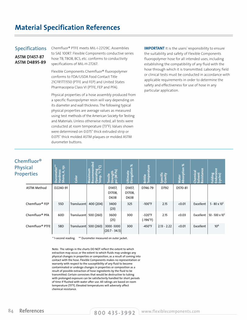
84
Chemfluor® PTFE meets MIL-I-22129C. Assemblies to SAE 100R7. Flexible Components conductive series hose TB, TBOB, BCS, etc. conforms to conductivity specifications of MIL-H-27267.
Flexible Components Chemfluor® fluoropolymer conforms to FDA/USDA Food Contact Title 21CFR177.1550 (PTFE and FEP) and United States Pharmacopeia Class VI (PTFE, FEP and PFA).
Physical properties of a hose assembly produced from a specific fluoropolymer resin will vary depending on its diameter and wall thickness. The following typical physical properties are average values as measured using test methods of the American Society for Testing and Materials. Unless otherwise noted, all tests were conducted at room temperature (73°F). Values shown were determined on 0.075" thick extruded strip or 0.075" thick molded ASTM plaques or molded ASTM durometer buttons.
IMPORTANT It is the users’ responsibility to ensure the suitability and safety of Flexible Components fluoropolymer hose for all intended uses, including establishing the compatibility of any fluid with the hose through which it is transmitted. Laboratory, field or clinical tests must be conducted in accordance with applicable requirements in order to determine the safety and effectiveness for use of hose in any particular application.
Material Specification References
SpecificationsASTM D1457-87ASTM D4895-89
Note: The ratings in the charts DO NOT reflect the extent to which extraction may occur, or the extent to which fluids may undergo any physical changes in properties or composition, as a result of coming into contact with the hose. Flexible Components makes no representation or warranty with respect to the susceptibility of any fluid to become contaminated or undergo changes in properties or composition as a result of possible extraction of hose ingredients by the fluid to be transmitted. Certain corrosives that would be destructive to tubing with prolonged exposure can be satisfactorily handled for short periods of time if flushed with water after use. All ratings are based on room temperature (73°F). Elevated temperatures will adversely affect chemical resistance.
* 1-second reading. ** Durometer measured on outer jacket.
ASTM Method D2240-91 D1457, D1457, D746-79 D792 D570-81 D1708, D1708, D638 D638
Chemfluor® FEP 55D Translucent 400(204) 3400 325 -100°F 2.15 <0.01 Excellent 5-80x103 (23)
Chemfluor® PFA 60D Translucent 500(260) 3600 300 -320°F 2.15 <0.03 Excellent 50-500x103 (25) (-196°F)
Chemfluor® PTFE 58D Translucent 500(260) 3000-5000 300 -450°F 2.13-2.22 <0.01 Excellent 106
(20.7-34.5)
Duro
met
er**
Har
dnes
sSh
ore,
A, 1
5s
Colo
r
Max
imum
Re
com
men
ded
Ope
ratin
g Te
mp.
°F (°
C)
Tens
ileSt
reng
thps
i (M
Pa)
Ulti
mat
eEl
onga
tion
%
Britt
leTe
mpe
ratu
re
Spec
ific
Grav
ity
Wat
er
Abso
rptio
n %
Chem
ical
So
lven
t Re
sist
ance
Fold
ing
Endu
ranc
e (c
ycle
s)
8 0 0 4 3 5 - 3 9 9 2 www.flexiblecomponents.comReferences
Chemfluor® Physical Properties

85
Most applications of Flexible Components Chemfluor® fluoropolymer hoses do not require the use of a conductive inner tube. Under certain applications, however, the potential for static discharge must be considered. Static electricity can be a hazard. Under those conditions where static discharge can occur, the use of conductive Flexible Components Chemfluor® PTFE hose is recommended.
When two different materials contact each other, electrons from one material can move across its boundary and associate with the other. These electrons align themselves with the material contacted. If the two materials are good conductors of electricity, the positive and negative electrons flow back and forth between them, keeping them in balance. If one or both are insulators, the flow will not occur. A charge will then build up on the surface of one of the materials. When the charge exceeds the electric strength of the material, dielectric breakdown results.
In applying this to Chemfluor® PTFE hose, we have to consider fluids and gases, which are poor conductors of electricity, and the flow rates of those fluids and gases. In order for a liquid or gas to be a poor electrical conductor it will generally satisfy one or both of the following conditions:
1. Be nonpolar; that is, an imbalance between protons and electrons, and/or
2. Contain a nonmixable component or a suspended solid; such as water in kerosene.
So when a liquid contacts a PTFE tube that isn’t a good conductor (white PTFE innercore), the result is phase separation, and the electric charge starts to build. The rate at which static electricity builds up now becomes a function of the fluid flow rate. When the dielectric strength of the PTFE tube is exceeded, the electric charge will puncture the tube wall and ground itself on the stainless steel braid of the hose. In hydraulics, high pressures generally mean high velocities. Historically, fluids were filtered upstream of the hoses using metallic filter elements. The metallic element helped to ground the charge. But, today, most filtration is done with paper type and glass-fiber elements that have a tendency to inject an electrostatic charge into the fluid they are filtering.
Fuels and steam are two specific areas of concern.Fuels are, for the most part, “nonconductive” liquids and have a resistivity greater than 108 ohm; i.e., gasoline and white spirits, hydrazine, benzene, diesel oils, etc. These fluids usually are transferred at fairly low velocities, but there still is a potential for an electrostatic discharge due to external factors, such as humidity and, to some extent, temperature. You should take all of these factors into account even at fluid velocities at or below 1 meter per second.
When using PTFE hose, you can offset the potential hazard of electrostatic discharge by using a conductive PTFE hose. Carbon is added to the Chemfluor® PTFE inner wall during manufacture. The carbon layer directs the electrostatic charge down the inner diameter of the hose to the metal end fittings. This prevents the charge from building up on the inner tube wall.
It’s important to examine any application where nonconductive fluids are used and any of the above conditions exist. This section is not meant to cover all conditions or situations involving fuels, steam or other media which may cause electrostatic buildup or potential discharge.
Following is a list of some of the chemicals which meet at least one of the criteria necessary to create electrostatic discharge:
Electrostatic Discharge
Application References
engineering guide material specification references • application references
Cyclohexane Decalin Diacetone Dibutyl Ether Dibutyl Phthalate Dibutyl Sebacate Dimethyl Phthalate Dioctyl Phthalate Dipentene Freon Fuel Oil Gasoline Hexane Hezene Hydraulic Oil Hydrazine Kerosene Lacquer Solvents
Lacquers Lacquers Decalin Mineral Oil n-Octane Naphtha Naphthalene Paint Petroleum Phosphate Ester Pinene Silicone Oils Skydrol 500 & 700 Steam Transformer Oil Toluene Turpentine Varnish Versilube
8 0 0 4 3 5 - 3 9 9 2www.flexiblecomponents.com References
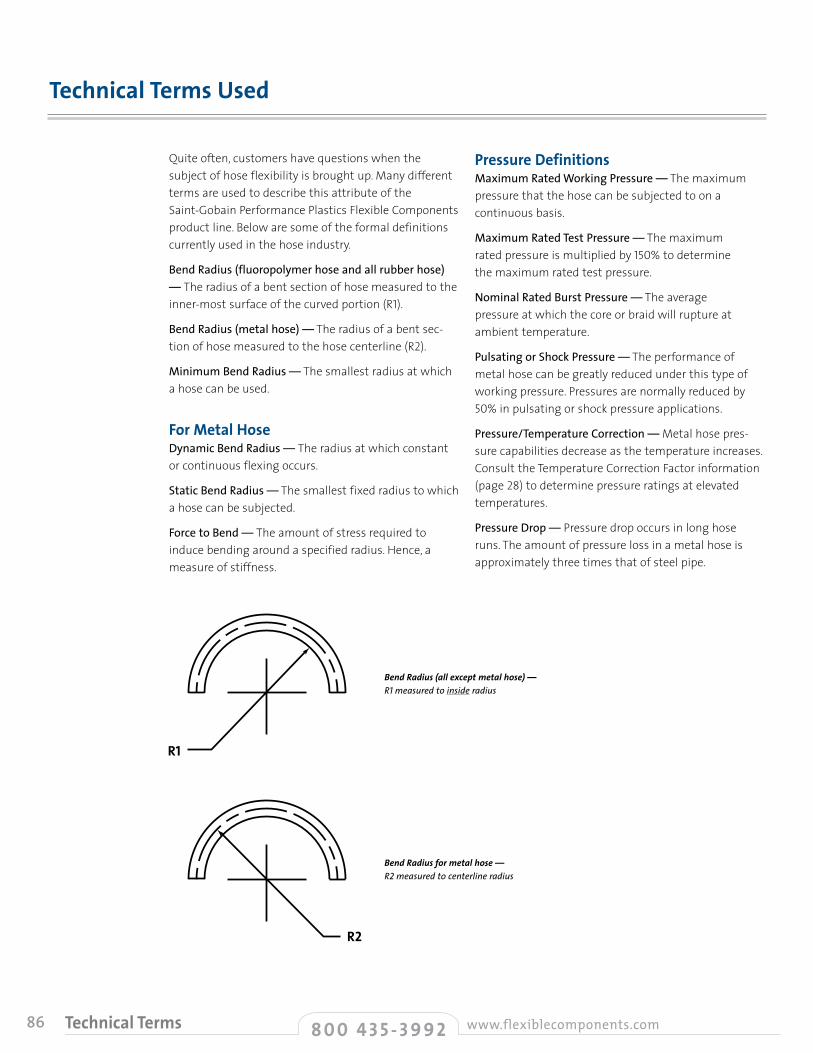
86
Quite often, customers have questions when the subject of hose flexibility is brought up. Many different terms are used to describe this attribute of the Saint-Gobain Performance Plastics Flexible Components product line. Below are some of the formal definitions currently used in the hose industry.
Bend Radius (fluoropolymer hose and all rubber hose) — The radius of a bent section of hose measured to the inner-most surface of the curved portion (R1).
Bend Radius (metal hose) — The radius of a bent sec-tion of hose measured to the hose centerline (R2).
Minimum Bend Radius — The smallest radius at which a hose can be used.
For Metal HoseDynamic Bend Radius — The radius at which constant or continuous flexing occurs.
Static Bend Radius — The smallest fixed radius to which a hose can be subjected.
Force to Bend — The amount of stress required to induce bending around a specified radius. Hence, a measure of stiffness.
Pressure DefinitionsMaximum Rated Working Pressure — The maximum pressure that the hose can be subjected to on a continuous basis.
Maximum Rated Test Pressure — The maximum rated pressure is multiplied by 150% to determine the maximum rated test pressure.
Nominal Rated Burst Pressure — The average pressure at which the core or braid will rupture at ambient temperature.
Pulsating or Shock Pressure — The performance of metal hose can be greatly reduced under this type of working pressure. Pressures are normally reduced by 50% in pulsating or shock pressure applications.
Pressure/Temperature Correction — Metal hose pres-sure capabilities decrease as the temperature increases. Consult the Temperature Correction Factor information (page 28) to determine pressure ratings at elevated temperatures.
Pressure Drop — Pressure drop occurs in long hose runs. The amount of pressure loss in a metal hose is approximately three times that of steel pipe.
Technical Terms Used
BendRadius(allexceptmetalhose)— R1 measured to inside radius
R1
BendRadiusformetalhose— R2 measured to centerline radius
R2
8 0 0 4 3 5 - 3 9 9 2 www.flexiblecomponents.comTechnical Terms

87
1. Examine the hose for any obvious damage. IF THE HOSE IS DAMAGED, DO NOT USE. Examples of damage may include slices to the cover, kinks, broken braid, and crushing of the hose (can reduce life and pressure rating).
2. Review application to ensure proper selection of hose has been made by examining materials, pressures, chemical compatibility, temperature and environment.
3. Hose movement should be restricted to a SINGLE PLANE (Drawing A) to minimize the resultant twisting (torque). Note: The flexing plane should also be the plane in which the bending occurs. Excessive bending will induce stress fatigue (Drawing B).
4. Axial movement should be eliminated. The hose should not be stretched or compressed along its longitudinal axis when installed in-line (Drawing C).
• Never use hose below minimum bend radius (Drawing D). Bend radii (measured to inside radius of fluoropolymer-lined hose and centerline for stainless steel metal hose) are given for individual products and sizes (consult factory for specific data). These values represent the minimum bend radius with which the hose can be properly installed. If these values are not maintained, the hose can fail prematurely. Note: In some cases, vacuum and pressure ratings are based on not exceeding 2 times minimum bend radius (consult factory for specific hose ratings).
• Do not allow severe bends (Drawing E). Severe bends can cause kinking in a hose or overstress the assembly/material, resulting in damage and ultimate failure. If severe bends cannot be avoided, use elbows designed to accommodate the direction change.
• Do not twist (torque) assembly along centerline during installation. The likelihood of leakage/failure increases for hoses that are twisted (torqued) during assembly. The proper use of floating flanges and swivel-type fittings (i.e., J.I.C.) can eliminate improper twisting.
Prior to Installation
Installation
General Hose Installation Precautions
engineering guide technical terms used • general hose installation precautions
A
B
C
movement
movement
D
E
W R O N G
W R O N G
W R O N G
W R O N G
W R O N G
8 0 0 4 3 5 - 3 9 9 2www.flexiblecomponents.com Hose Installation
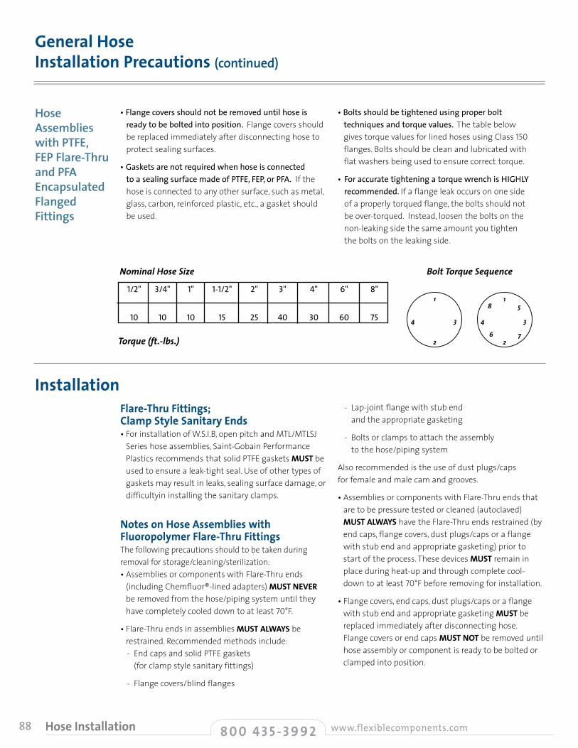
88
• Flange covers should not be removed until hose is ready to be bolted into position. Flange covers should be replaced immediately after disconnecting hose to protect sealing surfaces.
• Gaskets are not required when hose is connected to a sealing surface made of PTFE, FEP, or PFA. If the hose is connected to any other surface, such as metal, glass, carbon, reinforced plastic, etc., a gasket should be used.
• Bolts should be tightened using proper bolt techniques and torque values. The table below gives torque values for lined hoses using Class 150 flanges. Bolts should be clean and lubricated with flat washers being used to ensure correct torque.
• For accurate tightening a torque wrench is HIGHLY recommended. If a flange leak occurs on one side of a properly torqued flange, the bolts should not be over-torqued. Instead, loosen the bolts on the non-leaking side the same amount you tighten the bolts on the leaking side.
Flare-Thru Fittings;Clamp Style Sanitary Ends• For installation of W.S.I.B, open pitch and MTL/MTLSJ
Series hose assemblies, Saint-Gobain Performance Plastics recommends that solid PTFE gaskets MUST be used to ensure a leak-tight seal. Use of other types of gaskets may result in leaks, sealing surface damage, or difficultyin installing the sanitary clamps.
Notes on Hose Assemblies withFluoropolymer Flare-Thru Fittings The following precautions should to be taken duringremoval for storage/cleaning/sterilization:• Assemblies or components with Flare-Thru ends
(including Chemfluor®-lined adapters) MUST NEVER be removed from the hose/piping system until they have completely cooled down to at least 70°F.
• Flare-Thru ends in assemblies MUST ALWAYS be restrained. Recommended methods include: - End caps and solid PTFE gaskets
(for clamp style sanitary fittings)
- Flange covers/blind flanges
- Lap-joint flange with stub end and the appropriate gasketing
- Bolts or clamps to attach the assembly to the hose/piping system
Also recommended is the use of dust plugs/caps for female and male cam and grooves.
• Assemblies or components with Flare-Thru ends that are to be pressure tested or cleaned (autoclaved) MUST ALWAYS have the Flare-Thru ends restrained (by end caps, flange covers, dust plugs/caps or a flange with stub end and appropriate gasketing) prior to start of the process. These devices MUST remain in place during heat-up and through complete cool-down to at least 70°F before removing for installation.
• Flange covers, end caps, dust plugs/caps or a flange with stub end and appropriate gasketing MUST be replaced immediately after disconnecting hose. Flange covers or end caps MUST NOT be removed until hose assembly or component is ready to be bolted or clamped into position.
General Hose Installation Precautions (continued)
Installation
Hose Assemblies with PTFE, FEP Flare-Thru and PFA Encapsulated Flanged Fittings
Torque(ft.-lbs.)
NominalHoseSize
1/2" 3/4" 1" 1-1/2" 2" 3" 4" 6" 8"
10 10 10 15 25 40 30 60 75
1
2
4 3
18 5
6 72
4 3
BoltTorqueSequence
8 0 0 4 3 5 - 3 9 9 2 www.flexiblecomponents.comHose Installation
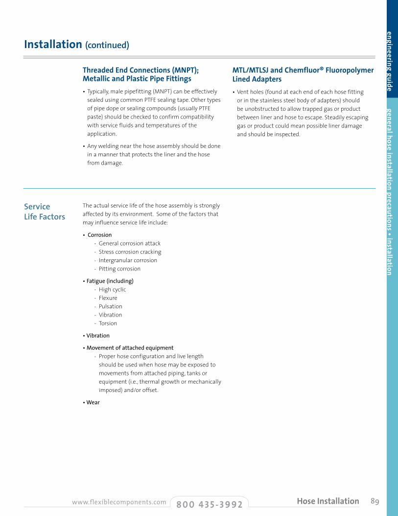
89
The actual service life of the hose assembly is strongly affected by its environment. Some of the factors that may influence service life include:
• Corrosion - General corrosion attack - Stress corrosion cracking - Intergranular corrosion - Pitting corrosion
• Fatigue (including) - High cyclic - Flexure - Pulsation - Vibration - Torsion
• Vibration
• Movement of attached equipment - Proper hose configuration and live length
should be used when hose may be exposed to movements from attached piping, tanks or equipment (i.e., thermal growth or mechanically imposed) and/or offset.
• Wear
Service Life Factors
Installation (continued)
engineering guide general hose installation precautions • installation
Threaded End Connections (MNPT); Metallic and Plastic Pipe Fittings• Typically, male pipefitting (MNPT) can be effectively
sealed using common PTFE sealing tape. Other types of pipe dope or sealing compounds (usually PTFE paste) should be checked to confirm compatibility with service fluids and temperatures of the application.
• Any welding near the hose assembly should be done in a manner that protects the liner and the hose from damage.
MTL/MTLSJ and Chemfluor® FluoropolymerLined Adapters• Vent holes (found at each end of each hose fitting
or in the stainless steel body of adapters) should be unobstructed to allow trapped gas or product between liner and hose to escape. Steadily escaping gas or product could mean possible liner damage and should be inspected.
8 0 0 4 3 5 - 3 9 9 2www.flexiblecomponents.com Hose Installation
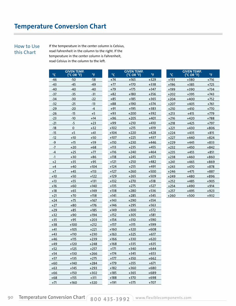
90
If the temperature in the center column is Celsius, read Fahrenheit in the column to the right. If the temperature in the center column is Fahrenheit, read Celsius in the column to the left.
Temperature Conversion Chart
How to Use this Chart
+193 +380 +716 +196 +385 +725 +199 +390 +734 +202 +395 +743 +204 +400 +752 +207 +405 +761 +210 +410 +770 +213 +415 +779 +216 +420 +788 +218 +425 +797 +221 +430 +806 +224 +435 +815 +227 +440 +824 +229 +445 +833 +232 +450 +842 +235 +455 +851 +238 +460 +860 +241 +465 +869 +243 +470 +878 +246 +475 +887 +249 +480 +896 +252 +485 +905 +254 +490 +914 +257 +495 +923 +260 +500 +932
-46 -50 -58 -43 -45 -49 -40 -40 -40 -37 -35 -31 -34 -30 -22 -32 -25 -13 -29 -20 -4 -26 -15 +5 -23 -10 +14 -21 -5 +23 -18 0 +32 -15 +5 +41 -12 +10 +50 -9 +15 +59 -7 +20 +68 -4 +25 +77 -1 +30 +86 +2 +35 +95 +4 +40 +104 +7 +45 +113 +10 +50 +122 +13 +55 +131 +16 +60 +140 +18 +65 +149 +21 +70 +158 +24 +75 +167 +27 +80 +176 +29 +85 +185 +32 +90 +194 +35 +95 +203 +38 +100 +212 +41 +105 +221 +43 +110 +230 +46 +115 +239 +49 +120 +248 +52 +125 +257 +54 +130 +266 +57 +135 +275 +60 +140 +284 +63 +145 +293 +66 +150 +302 +68 +155 +311 +71 +160 +320
+74 +165 +329 +77 +170 +338 +79 +175 +347 +82 +180 +356 +85 +185 +365 +88 +190 +374 +91 +195 +383 +93 +200 +392 +96 +205 +401 +99 +210 +410 +102 +215 +419 +104 +220 +428 +107 +225 +437 +110 +230 +446 +113 +235 +455 +116 +240 +464 +118 +245 +473 +121 +250 +482 +124 +255 +491 +127 +260 +500 +129 +265 +509 +132 +270 +518 +135 +275 +527 +138 +280 +536 +141 +285 +545 +143 +290 +554 +146 +295 +563 +149 +300 +572 +152 +305 +581 +154 +310 +590 +157 +315 +599 +160 +320 +608 +163 +325 +617 +166 +330 +620 +168 +335 +635 +171 +340 +644 +174 +345 +653 +177 +350 +662 +179 +355 +671 +182 +360 +680 +185 +365 +689 +188 +370 +698 +191 +375 +707
GIVEN TEMP. °C (°C OR °F) °F
GIVEN TEMP. °C (°C OR °F) °F
GIVEN TEMP. °C (°C OR °F) °F
8 0 0 4 3 5 - 3 9 9 2 www.flexiblecomponents.comTemperature Conversion Chart

91
Three types are used in Flexible Components hose assemblies:• PTFE (sometimes referred to as TFE) (Polyetrafluoroethylene) • FEP (Copolymer of tetrafluoroethylene and hexafluoropropylene) • PFA (Copolymer of tetrafluoroethylene and perfluoroalkyl)
The various types of fluoropolymer are ideal as hose materials because of the following characteristics: • Insolubility and inertness to chemical attack • Purity • High thermal stability and upper service temperature • High melting points • Low coefficient of friction • Low water absorptivity • Low dielectric constant and dissipation factor • Excellent weatherability • Flame resistance
Flexible Components Chemfluor® PTFE, PFA and FEP resins are either approved by the Food and Drug Administration or US Pharmacopeia Class VI. See below for specific details.
Chemical ResistanceSpecial care must be exercised when the following materials are to be conveyed through a Flexible Components Chemfluor® hose. The first three, quite simply, should never be used with Chemfluor® PTFE, FEP or PFA. The remaining 14 can be used, but special consideration should be given when applications require both high temperature and impact resistance or involve high temperature and pressure in combination.
Articles Intended for Food ContactReference: FDA 21CFR177.1550 Perfluorocarbon Resins Covers Chemfluor® PTFE and FEP resins, which may be safely used as articles or components of articles intended to contact food in compliance with this regulation. 3-A Sanitary Standards 3-A is a non-profit association that has established comprehensive objectives to develop and maintain uniform standards and practices for sanitary (hygienic) design and fabrication in food and beverage industries.
USDA AcceptanceThe Department of Agriculture (USDA) has accepted Chemfluor® PTFE and FEP fluoropolymer resins that comply with 21CFR177.1550 as components of materials in direct contact with meat or poultry food products prepared under federal inspection.
US Pharmacopeia Class VISamples of Chemfluor® PTFE, FEP and PFA (white/natural and black anti-static PTFE and PFA) have been tested in accordance with USP protocol, and all meet the requirements for Class VI plastics. USP testing was done to support the use of these fluoropolymers in pharmaceutical processing and food processing applications. While USP Class VI certification is not required for pharmaceutical processing, many pharmaceutical customers seeking ISO-9000 certification have requested it.
Colorants in Polymers FDA Reference: 21CFR178.3297 Colorants for PolymersThis regulation permits certain colorants for use in polymers intended for food contact. Included are TiO2, iron oxides, all-gas channel black (carbon black) and ultra marine colorants.
Chemfluor® Fluoropolymer Resins
Purity
Chemfluor® References
engineering guide temperature conversion chart • Chem
fluor® references
Never• Elemental Sodium• Elemental Potassium
• Elemental Lithium
Industry Approval and Compliance References
8 0 0 4 3 5 - 3 9 9 2www.flexiblecomponents.com Chemfluor® References
Need Consideration• Fluorine (F2)
(Fluorine is absorbed into the Chemfluor® resin)
• Chlorine Tri-fluoride (CIF3) (can be sensitive to impact ignition)
• Bromine Tri-fluoride• Iodine Pentafluoride• Oxygen Difluoride• Chlorine Difluoride• 80% Sodium Hydroxide
• 80% Potassium Hydroxide
• Borane (B2H6) (Only at 400°F to 500°F)
• Aluminum Chloride (at elevated temperatures)
• Ammonia (NH3)• Amines (R-NH2)
(at elevated temperatures)• Imine (R-NH)• 70% Nitric Acid – slow
oxidative attack only under pressure at 480°F

92
28-Day Immersions at 73° E = Excellent G = Good F = Fair U = Not Recommended
No. Environment, Conc. % Chem
fluor
® FE
PCh
emflu
or®
PFA
Chem
fluor
® PT
FE
Chem
fluor
® FE
PCh
emflu
or®
PFA
Chem
fluor
® PT
FE
Chem
fluor
® FE
PCh
emflu
or®
PFA
Chem
fluor
® PT
FE
No. Environment, Conc. % No. Environment, Conc. %
Environmental % Conc. * w = Water alc. = Alcohol
Chemical Resistance Ratings
1 Acetaldehyde E E E
2 Acetamide, 67% in w E E E
3 Acetate Solvents E E E
4 Acetic Acid, 10% in w E E E
5 Acetic Acid, 50-60% in w E E E
6 Acetic Acid, Glacial, 100% E E E
7 Acetic Anhydride E E E
8 Acetone E E E
9 Acetonitrile E E E
10 Acetyl Bromide E E E
11 Acetyl Chloride E E E
12 Acetylene Gas E E E
13 Acrylonitrile E E E
14 Adipic Acid, 100% in alc E E E
15 Air E E E
16 Alcohols General E E E
17 Aliphatic Hydrocarbons E E E
18 Alkyl Alcohol E E E
19 Alum, 5% in w E E E
20 Aluminum Chloride, 53% in w E E E
21 Aluminum Fluoride, 0.1% in w E E E
22 Aluminum Hydroxide, 2% in w E E E
23 Aluminum Nitrate, 39% in w E E E
24 Aluminum Sulfate, 50% in w E E E
25 Aluminum Salts E E E
26 Amines E E E
27 Ammonia Gas E E E
28 Ammonia, Anhydrous Liquid E E E
29 Ammonium Acetate, 45% in w E E E
30 Ammonium Bifluoride, 50% in w E E E
31 Ammonium Carbonate, 50% in w E E E
32 Ammonium Chloride, 23% in w E E E
33 Ammonium Hydroxide, 5-10% in w E E E
34 Ammonium Hydroxide, 30% in w E E E
35 Ammonium Nitrate, 54% in w E E E
36 Ammonium Persulfate, 30% in w E E E
37 Ammonium Phosphate, 21% in w E E E
38 Ammonium Salts E E E
39 Ammonium Sulfate, 30% in w E E E
40 Amyl Acetate E E E
41 Amyl Alcohol E E E
42 Amyl Chloride E E E
43 Aniline E E E
44 Aniline Hydrochloride E E E
45 Antimony Salts E E E
46 Antimony Trichloride E E E
47 Aqua Regia G E E
48 Aromatic Hydrocarbons E E E
49 Arsenic Acid, 20% in w E E E
50 Arsenic Salts E E E
51 ASTM Reference No. 1 Oil E E E
52 ASTM Reference No. 2 Oil E E E
53 ASTM Reference No. 3 Oil E E E
54 Barium Carbonate, 1% in w E E E
55 Barium Chloride, 27% in w E E E
56 Barium Hydroxide, 5% in w E E E
57 Barium Salts E E E
58 Barium Sulfate, <1% in dilute acids E E E
59 Barium Sulfide E E E
60 Beer E E E
61 Benzaldehyde E E E
62 Benzene E E E
63 Benzenesulfonic Acid E E E
64 Benzoic Acid E E E
65 Benzyl Alcohol E E E
66 Bleach Liquor, 22% in w E E E
67 Borax, 6% in w E E E
68 Boric Acid, 4% in w E E E
69 Bromine, Anhydrous Liquid U U U
70 Butadiene E E E
71 Butane E E E
72 Butyl Acetate E E E
73 Butyl Alcohol E E E
74 Butyric Acid E E E
75 Calcium Bisulfite, 1% in w E E E
76 Calcium Carbonate, 25% in dilute acids E E E
77 Calcium Chlorate, 30% in w E E E
78 Calcium Chloride, 30% in w E E E
79 Calcium Hydroxide, 10% in glycerol E E E
80 Calcium Hypochlorite, 20% in w E E E
81 Calcium Nitrate, 55% in w E E E
82 Calcium Oxide, 3% in w E E E
83 Calcium Salts E E E
84 Calcium Sulfate, 1% in w E E E
85 Carbon Dioxide, Wet/Dry E E E
86 Carbon Disulfide E E E
87 Carbonic Acid E E E
88 Carbon Monoxide E E E
89 Carbon Tetrachloride E E E
90 Castor Oil E E E
91 Cellosolve E E E
92 Cellosolve Acetate E E E
93 Chlorine, Dry Gas E E E
94 Chlorine, Wet Gas E E E
95 Chloroacetic Acid, 20% in w E E E
96 Chlorobenzene, Mono, Di, Tri E E E
97 Chloroform E E E
98 Chlorosulfonic Acid E E E
99 Chromic Acid, 10-20% in w E E E
100 Chromic Acid, 50% in w E E E
101 Chromium Salts E E E
102 Citric Acid, 10-20% in w E E E
103 Coconut Oil E E E
104 Copper Salts E E E
105 Corn Syrup E E E
106 Cottonseed Oil E E E
107 Cresol (m, o, or p) E E E
108 Cresylic Acid E E E
Three Chemfluor® Fluoropolymer Hose Products in 362 EnvironmentsThe ratings in the charts are based on the results of both laboratory and field tests. They reflect the relative capabilities of various Chemfluor® fluoropolymer resins to withstand specific chemicals. All ratings are based on room temperature. Although we believe these ratings
to be thoroughly reliable, no guarantee is expressed or should be implied. It is suggested that the user conduct tests using the conditions of the application prior to specifying a particular hose.
8 0 0 4 3 5 - 3 9 9 2 www.flexiblecomponents.comChemical Resistance Ratings
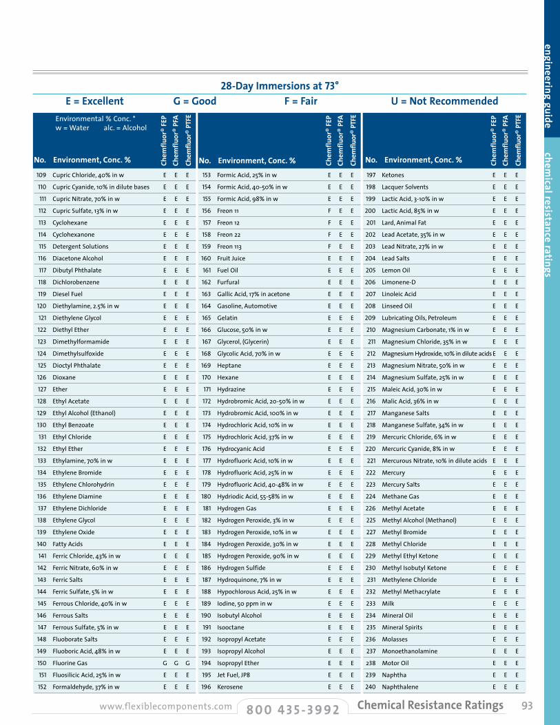
28-Day Immersions at 73° E = Excellent G = Good F = Fair U = Not Recommended
No. Environment, Conc. % No. Environment, Conc. % No. Environment, Conc. %
Environmental % Conc. * w = Water alc. = Alcohol
93
engineering guide chemical resistance ratings
109 Cupric Chloride, 40% in w E E E
110 Cupric Cyanide, 10% in dilute bases E E E
111 Cupric Nitrate, 70% in w E E E
112 Cupric Sulfate, 13% in w E E E
113 Cyclohexane E E E
114 Cyclohexanone E E E
115 Detergent Solutions E E E
116 Diacetone Alcohol E E E
117 Dibutyl Phthalate E E E
118 Dichlorobenzene E E E
119 Diesel Fuel E E E
120 Diethylamine, 2.5% in w E E E
121 Diethylene Glycol E E E
122 Diethyl Ether E E E
123 Dimethylformamide E E E
124 Dimethylsulfoxide E E E
125 Dioctyl Phthalate E E E
126 Dioxane E E E
127 Ether E E E
128 Ethyl Acetate E E E
129 Ethyl Alcohol (Ethanol) E E E
130 Ethyl Benzoate E E E
131 Ethyl Chloride E E E
132 Ethyl Ether E E E
133 Ethylamine, 70% in w E E E
134 Ethylene Bromide E E E
135 Ethylene Chlorohydrin E E E
136 Ethylene Diamine E E E
137 Ethylene Dichloride E E E
138 Ethylene Glycol E E E
139 Ethylene Oxide E E E
140 Fatty Acids E E E
141 Ferric Chloride, 43% in w E E E
142 Ferric Nitrate, 60% in w E E E
143 Ferric Salts E E E
144 Ferric Sulfate, 5% in w E E E
145 Ferrous Chloride, 40% in w E E E
146 Ferrous Salts E E E
147 Ferrous Sulfate, 5% in w E E E
148 Fluoborate Salts E E E
149 Fluoboric Acid, 48% in w E E E
150 Fluorine Gas G G G
151 Fluosilicic Acid, 25% in w E E E
152 Formaldehyde, 37% in w E E E
153 Formic Acid, 25% in w E E E
154 Formic Acid, 40-50% in w E E E
155 Formic Acid, 98% in w E E E
156 Freon 11 F E E
157 Freon 12 F E E
158 Freon 22 F E E
159 Freon 113 F E E
160 Fruit Juice E E E
161 Fuel Oil E E E
162 Furfural E E E
163 Gallic Acid, 17% in acetone E E E
164 Gasoline, Automotive E E E
165 Gelatin E E E
166 Glucose, 50% in w E E E
167 Glycerol, (Glycerin) E E E
168 Glycolic Acid, 70% in w E E E
169 Heptane E E E
170 Hexane E E E
171 Hydrazine E E E
172 Hydrobromic Acid, 20-50% in w E E E
173 Hydrobromic Acid, 100% in w E E E
174 Hydrochloric Acid, 10% in w E E E
175 Hydrochloric Acid, 37% in w E E E
176 Hydrocyanic Acid E E E
177 Hydrofluoric Acid, 10% in w E E E
178 Hydrofluoric Acid, 25% in w E E E
179 Hydrofluoric Acid, 40-48% in w E E E
180 Hydriodic Acid, 55-58% in w E E E
181 Hydrogen Gas E E E
182 Hydrogen Peroxide, 3% in w E E E
183 Hydrogen Peroxide, 10% in w E E E
184 Hydrogen Peroxide, 30% in w E E E
185 Hydrogen Peroxide, 90% in w E E E
186 Hydrogen Sulfide E E E
187 Hydroquinone, 7% in w E E E
188 Hypochlorous Acid, 25% in w E E E
189 Iodine, 50 ppm in w E E E
190 Isobutyl Alcohol E E E
191 Isooctane E E E
192 Isopropyl Acetate E E E
193 Isopropyl Alcohol E E E
194 Isopropyl Ether E E E
195 Jet Fuel, JP8 E E E
196 Kerosene E E E
197 Ketones E E E
198 Lacquer Solvents E E E
199 Lactic Acid, 3-10% in w E E E
200 Lactic Acid, 85% in w E E E
201 Lard, Animal Fat E E E
202 Lead Acetate, 35% in w E E E
203 Lead Nitrate, 27% in w E E E
204 Lead Salts E E E
205 Lemon Oil E E E
206 Limonene-D E E E
207 Linoleic Acid E E E
208 Linseed Oil E E E
209 Lubricating Oils, Petroleum E E E
210 Magnesium Carbonate, 1% in w E E E
211 Magnesium Chloride, 35% in w E E E
212 Magnesium Hydroxide, 10% in dilute acids E E E
213 Magnesium Nitrate, 50% in w E E E
214 Magnesium Sulfate, 25% in w E E E
215 Maleic Acid, 30% in w E E E
216 Malic Acid, 36% in w E E E
217 Manganese Salts E E E
218 Manganese Sulfate, 34% in w E E E
219 Mercuric Chloride, 6% in w E E E
220 Mercuric Cyanide, 8% in w E E E
221 Mercurous Nitrate, 10% in dilute acids E E E
222 Mercury E E E
223 Mercury Salts E E E
224 Methane Gas E E E
226 Methyl Acetate E E E
225 Methyl Alcohol (Methanol) E E E
227 Methyl Bromide E E E
228 Methyl Chloride E E E
229 Methyl Ethyl Ketone E E E
230 Methyl Isobutyl Ketone E E E
231 Methylene Chloride E E E
232 Methyl Methacrylate E E E
233 Milk E E E
234 Mineral Oil E E E
235 Mineral Spirits E E E
236 Molasses E E E
237 Monoethanolamine E E E
238 Motor Oil E E E
239 Naphtha E E E
240 Naphthalene E E E
8 0 0 4 3 5 - 3 9 9 2www.flexiblecomponents.com Chemical Resistance Ratings
Chem
fluor
® FE
PCh
emflu
or®
PFA
Chem
fluor
® PT
FE
Chem
fluor
® FE
PCh
emflu
or®
PFA
Chem
fluor
® PT
FE
Chem
fluor
® FE
PCh
emflu
or®
PFA
Chem
fluor
® PT
FE
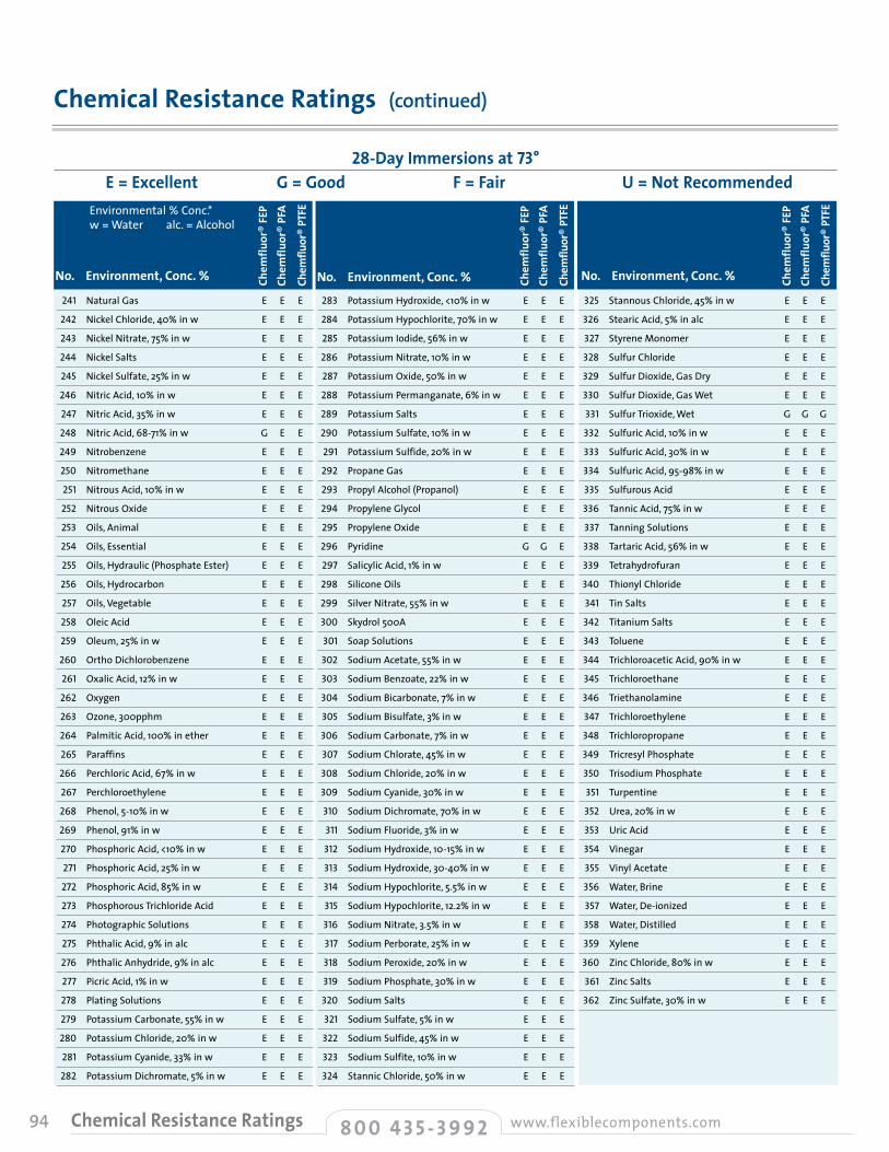
94
Chemical Resistance Ratings (continued)
28-Day Immersions at 73° E = Excellent G = Good F = Fair U = Not Recommended
No. Environment, Conc. % No. Environment, Conc. % No. Environment, Conc. %
Environmental % Conc. * w = Water alc. = Alcohol
241 Natural Gas E E E
242 Nickel Chloride, 40% in w E E E
243 Nickel Nitrate, 75% in w E E E
244 Nickel Salts E E E
245 Nickel Sulfate, 25% in w E E E
246 Nitric Acid, 10% in w E E E
247 Nitric Acid, 35% in w E E E
248 Nitric Acid, 68-71% in w G E E
249 Nitrobenzene E E E
250 Nitromethane E E E
251 Nitrous Acid, 10% in w E E E
252 Nitrous Oxide E E E
253 Oils, Animal E E E
254 Oils, Essential E E E
255 Oils, Hydraulic (Phosphate Ester) E E E
256 Oils, Hydrocarbon E E E
257 Oils, Vegetable E E E
258 Oleic Acid E E E
259 Oleum, 25% in w E E E
260 Ortho Dichlorobenzene E E E
261 Oxalic Acid, 12% in w E E E
262 Oxygen E E E
263 Ozone, 300pphm E E E
264 Palmitic Acid, 100% in ether E E E
265 Paraffins E E E
266 Perchloric Acid, 67% in w E E E
267 Perchloroethylene E E E
268 Phenol, 5-10% in w E E E
269 Phenol, 91% in w E E E
270 Phosphoric Acid, <10% in w E E E
271 Phosphoric Acid, 25% in w E E E
272 Phosphoric Acid, 85% in w E E E
273 Phosphorous Trichloride Acid E E E
274 Photographic Solutions E E E
275 Phthalic Acid, 9% in alc E E E
276 Phthalic Anhydride, 9% in alc E E E
277 Picric Acid, 1% in w E E E
278 Plating Solutions E E E
279 Potassium Carbonate, 55% in w E E E
280 Potassium Chloride, 20% in w E E E
281 Potassium Cyanide, 33% in w E E E
282 Potassium Dichromate, 5% in w E E E
283 Potassium Hydroxide, <10% in w E E E
284 Potassium Hypochlorite, 70% in w E E E
285 Potassium Iodide, 56% in w E E E
286 Potassium Nitrate, 10% in w E E E
287 Potassium Oxide, 50% in w E E E
288 Potassium Permanganate, 6% in w E E E
289 Potassium Salts E E E
290 Potassium Sulfate, 10% in w E E E
291 Potassium Sulfide, 20% in w E E E
292 Propane Gas E E E
293 Propyl Alcohol (Propanol) E E E
294 Propylene Glycol E E E
295 Propylene Oxide E E E
296 Pyridine G G E
297 Salicylic Acid, 1% in w E E E
298 Silicone Oils E E E
299 Silver Nitrate, 55% in w E E E
300 Skydrol 500A E E E
301 Soap Solutions E E E
302 Sodium Acetate, 55% in w E E E
303 Sodium Benzoate, 22% in w E E E
304 Sodium Bicarbonate, 7% in w E E E
305 Sodium Bisulfate, 3% in w E E E
306 Sodium Carbonate, 7% in w E E E
307 Sodium Chlorate, 45% in w E E E
308 Sodium Chloride, 20% in w E E E
309 Sodium Cyanide, 30% in w E E E
310 Sodium Dichromate, 70% in w E E E
311 Sodium Fluoride, 3% in w E E E
312 Sodium Hydroxide, 10-15% in w E E E
313 Sodium Hydroxide, 30-40% in w E E E
314 Sodium Hypochlorite, 5.5% in w E E E
315 Sodium Hypochlorite, 12.2% in w E E E
316 Sodium Nitrate, 3.5% in w E E E
317 Sodium Perborate, 25% in w E E E
318 Sodium Peroxide, 20% in w E E E
319 Sodium Phosphate, 30% in w E E E
320 Sodium Salts E E E
321 Sodium Sulfate, 5% in w E E E
322 Sodium Sulfide, 45% in w E E E
323 Sodium Sulfite, 10% in w E E E
324 Stannic Chloride, 50% in w E E E
325 Stannous Chloride, 45% in w E E E
326 Stearic Acid, 5% in alc E E E
327 Styrene Monomer E E E
328 Sulfur Chloride E E E
329 Sulfur Dioxide, Gas Dry E E E
330 Sulfur Dioxide, Gas Wet E E E
331 Sulfur Trioxide, Wet G G G
332 Sulfuric Acid, 10% in w E E E
333 Sulfuric Acid, 30% in w E E E
334 Sulfuric Acid, 95-98% in w E E E
335 Sulfurous Acid E E E
336 Tannic Acid, 75% in w E E E
337 Tanning Solutions E E E
338 Tartaric Acid, 56% in w E E E
339 Tetrahydrofuran E E E
340 Thionyl Chloride E E E
341 Tin Salts E E E
342 Titanium Salts E E E
343 Toluene E E E
344 Trichloroacetic Acid, 90% in w E E E
345 Trichloroethane E E E
346 Triethanolamine E E E
347 Trichloroethylene E E E
348 Trichloropropane E E E
349 Tricresyl Phosphate E E E
350 Trisodium Phosphate E E E
351 Turpentine E E E
352 Urea, 20% in w E E E
353 Uric Acid E E E
354 Vinegar E E E
355 Vinyl Acetate E E E
356 Water, Brine E E E
357 Water, De-ionized E E E
358 Water, Distilled E E E
359 Xylene E E E
360 Zinc Chloride, 80% in w E E E
361 Zinc Salts E E E
362 Zinc Sulfate, 30% in w E E E
8 0 0 4 3 5 - 3 9 9 2 www.flexiblecomponents.comChemical Resistance Ratings
Chem
fluor
® FE
PCh
emflu
or®
PFA
Chem
fluor
® PT
FE
Chem
fluor
® FE
PCh
emflu
or®
PFA
Chem
fluor
® PT
FE
Chem
fluor
® FE
PCh
emflu
or®
PFA
Chem
fluor
® PT
FE
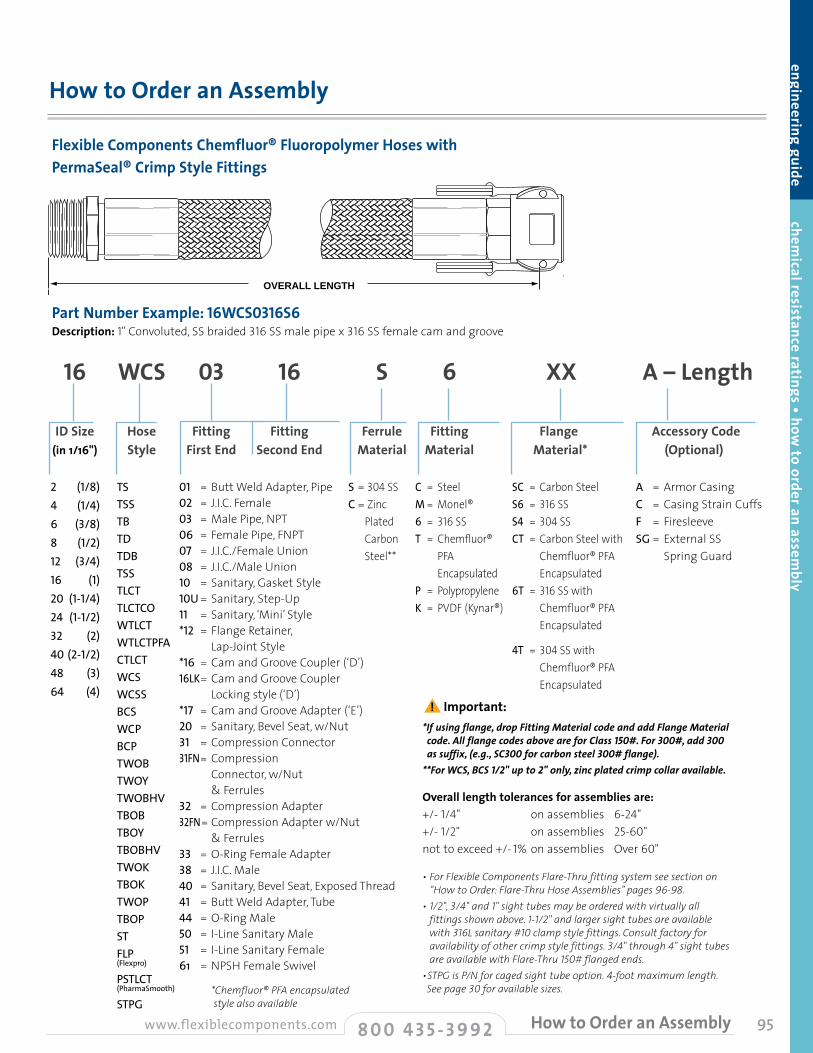
95
How to Order an Assembly
engineering guide chemical resistance ratings • how
to order an assembly
Flexible Components Chemfluor® Fluoropolymer Hoses with PermaSeal® Crimp Style Fittings
Part Number Example: 16WCS0316S6Description: 1" Convoluted, SS braided 316 SS male pipe x 316 SS female cam and groove
16 WCS 03 16
ID Size Hose Fitting Fitting (in 1/16") Style First End Second End
A – Length
Accessory Code (Optional)
S
Ferrule Material
6
Fitting Material
XX
Flange Material*
2 (1/8)4 (1/4)6 (3/8)8 (1/2)12 (3/4)16 (1)20(1-1/4)24 (1-1/2)32 (2)40(2-1/2)48 (3)64 (4)
TS TSS TB TD TDB TSS TLCTTLCTCO WTLCTWTLCTPFA CTLCT WCS WCSS BCS WCP BCP TWOBTWOYTWOBHV TBOB TBOYTBOBHV TWOK TBOK TWOP TBOP STFLP(Flexpro)
PSTLCT(PharmaSmooth)
STPG
01 = Butt Weld Adapter, Pipe 02 = J.I.C. Female 03 = Male Pipe, NPT 06 = Female Pipe, FNPT 07 = J.I.C./Female Union 08 = J.I.C./Male Union 10 = Sanitary, Gasket Style 10U = Sanitary, Step-Up 11 = Sanitary, ‘Mini’ Style *12 = Flange Retainer, Lap-Joint Style *16 = Cam and Groove Coupler (‘D’) 16LK= Cam and Groove Coupler Locking style (‘D’) *17 = Cam and Groove Adapter (‘E’) 20 = Sanitary, Bevel Seat, w/Nut 31 = Compression Connector 31FN = Compression Connector, w/Nut & Ferrules 32 = Compression Adapter 32FN= Compression Adapter w/Nut & Ferrules 33 = O-Ring Female Adapter 38 = J.I.C. Male 40 = Sanitary, Bevel Seat, Exposed Thread 41 = Butt Weld Adapter, Tube 44 = O-Ring Male 50 = I-Line Sanitary Male 51 = I-Line Sanitary Female 61 = NPSH Female Swivel *Chemfluor® PFA encapsulated style also available
A = Armor CasingC = Casing Strain CuffsF = FiresleeveSG = External SS
Spring Guard
S = 304 SSC = Zinc
Plated Carbon Steel**
C = SteelM = Monel®6 = 316 SST = Chemfluor®
PFA Encapsulated
P = PolypropyleneK = PVDF (Kynar®)
Overall length tolerances for assemblies are:+/- 1/4" on assemblies 6-24" +/- 1/2" on assemblies 25-60" not to exceed +/- 1% on assemblies Over 60"
OVERALL LENGTH
OVERALL LENGTHOVERALL LENGTH
• For Flexible Components Flare-Thru fitting system see section on “How to Order: Flare-Thru Hose Assemblies” pages 96-98.
• 1/2", 3/4" and 1" sight tubes may be ordered with virtually all fittings shown above. 1-1/2" and larger sight tubes are available with 316L sanitary #10 clamp style fittings. Consult factory for availability of other crimp style fittings. 3/4" through 4" sight tubes are available with Flare-Thru 150# flanged ends.
• STPG is P/N for caged sight tube option. 4-foot maximum length. See page 30 for available sizes.
*Ifusingflange,dropFittingMaterialcodeandaddFlangeMaterialcode.AllflangecodesaboveareforClass150#.For300#,add 300assuffix,(e.g.,SC300 forcarbonsteel300#flange).**ForWCS,BCS1/2"upto2"only,zincplatedcrimpcollaravailable.
SC = Carbon Steel S6 = 316 SSS4 = 304 SS CT = Carbon Steel with
Chemfluor® PFA Encapsulated
6T = 316 SS with Chemfluor® PFA Encapsulated
4T = 304 SS with Chemfluor® PFA Encapsulated
8 0 0 4 3 5 - 3 9 9 2www.flexiblecomponents.com How to Order an Assembly
! Important:
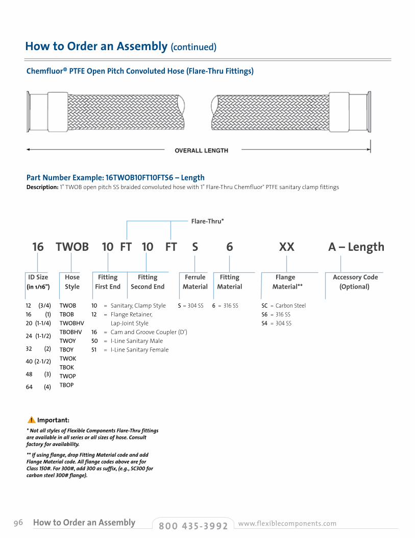
96
How to Order an Assembly (continued)
Chemfluor® PTFE Open Pitch Convoluted Hose (Flare-Thru Fittings)
16 TWOB 10 FT 10 FT
ID Size Hose Fitting Fitting (in 1/16") Style First End Second End
12 (3/4)16 (1)20(1-1/4)
24 (1-1/2)
32 (2)
40(2-1/2)
48 (3)
64 (4)
TWOB TBOB TWOBHVTBOBHVTWOYTBOYTWOKTBOKTWOPTBOP
10 = Sanitary, Clamp Style 12 = Flange Retainer, Lap-Joint Style 16 = Cam and Groove Coupler (D’) 50 = I-Line Sanitary Male 51 = I-Line Sanitary Female
Flare-Thru*
8 0 0 4 3 5 - 3 9 9 2 www.flexiblecomponents.comHow to Order an Assembly
Part Number Example: 16TWOB10FT10FTS6 – Length Description: 1" TWOB open pitch SS braided convoluted hose with 1" Flare-Thru Chemfluor® PTFE sanitary clamp fittings
A – Length
Accessory Code (Optional)
S
Ferrule Material
6
Fitting Material
XX
Flange Material**
S = 304 SS 6 = 316 SS SC = Carbon Steel S6 = 316 SSS4 = 304 SS
*NotallstylesofFlexibleComponentsFlare-Thrufittingsareavailableinallseriesorallsizesofhose.Consultfactoryforavailability.
**Ifusingflange,dropFittingMaterialcodeandaddFlangeMaterialcode.AllflangecodesaboveareforClass150#.For300#,add300assuffix,(e.g.,SC300forcarbonsteel300#flange).
! Important:
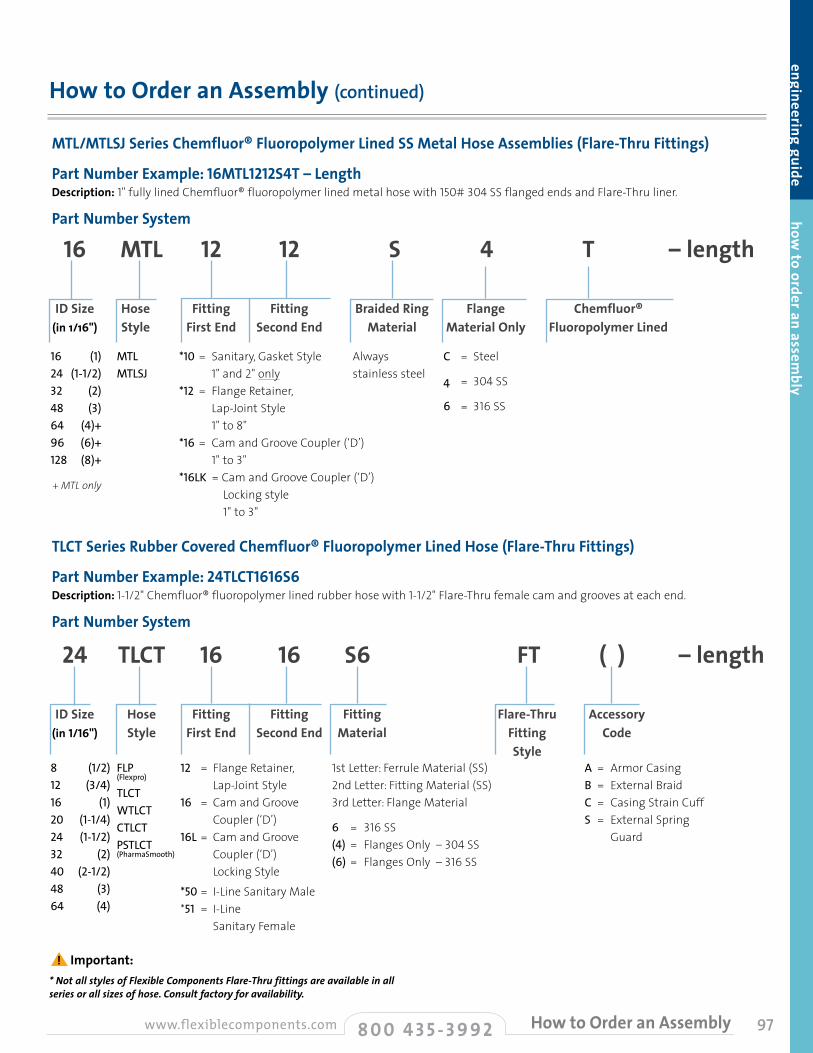
97
engineering guide how to order an assem
bly
How to Order an Assembly (continued)
8 0 0 4 3 5 - 3 9 9 2www.flexiblecomponents.com How to Order an Assembly
MTL/MTLSJ Series Chemfluor® Fluoropolymer Lined SS Metal Hose Assemblies (Flare-Thru Fittings)
Part Number Example: 16MTL1212S4T – LengthDescription: 1" fully lined Chemfluor® fluoropolymer lined metal hose with 150# 304 SS flanged ends and Flare-Thru liner.
Part Number System
16 MTL 12 12 S 4 T – length
ID Size Hose Fitting Fitting Braided Ring Flange Chemfluor® (in 1/16") Style First End Second End Material Material Only Fluoropolymer Lined
16 (1)24 (1-1/2)32 (2)48 (3)64 (4)+96 (6)+128 (8)+
+ MTL only
MTLMTLSJ
*10 = Sanitary, Gasket Style 1" and 2" only *12 = Flange Retainer, Lap-Joint Style 1" to 8"*16 = Cam and Groove Coupler (‘D’) 1" to 3"*16LK = Cam and Groove Coupler (‘D’) Locking style 1" to 3"
C = Steel
4 = 304 SS
6 = 316 SS
Always stainless steel
TLCT Series Rubber Covered Chemfluor® Fluoropolymer Lined Hose (Flare-Thru Fittings)
Part Number Example: 24TLCT1616S6 Description: 1-1/2" Chemfluor® fluoropolymer lined rubber hose with 1-1/2" Flare-Thru female cam and grooves at each end.
Part Number System
24 TLCT 16 16 S6 FT ( ) – length
ID Size Hose Fitting Fitting Fitting Flare-Thru Accessory (in 1/16") Style First End Second End Material Fitting Code Style 8 (1/2)12 (3/4)16 (1)20 (1-1/4)24 (1-1/2)32 (2)40 (2-1/2)48 (3)64 (4)
FLP(Flexpro)
TLCT WTLCT CTLCTPSTLCT(PharmaSmooth)
12 = Flange Retainer, Lap-Joint Style 16 = Cam and Groove Coupler (‘D’) 16L = Cam and Groove
Coupler (‘D’) Locking Style
*50 = I-Line Sanitary Male *51 = I-Line Sanitary Female
A = Armor CasingB = External BraidC = Casing Strain CuffS = External Spring
Guard
1st Letter: Ferrule Material (SS) 2nd Letter: Fitting Material (SS) 3rd Letter: Flange Material
6 = 316 SS (4) = Flanges Only – 304 SS (6) = Flanges Only – 316 SS
*NotallstylesofFlexibleComponentsFlare-Thrufittingsareavailableinallseriesorallsizesofhose.Consultfactoryforavailability.
! Important:
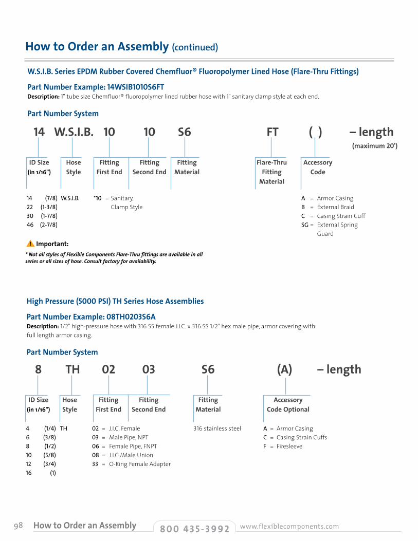
98
How to Order an Assembly (continued)
8 0 0 4 3 5 - 3 9 9 2 www.flexiblecomponents.comHow to Order an Assembly
W.S.I.B. Series EPDM Rubber Covered Chemfluor® Fluoropolymer Lined Hose (Flare-Thru Fittings)
Part Number Example: 14WSIB1010S6FTDescription: 1" tube size Chemfluor® fluoropolymer lined rubber hose with 1" sanitary clamp style at each end.
Part Number System
14 W.S.I.B. 10 10 S6 FT ( ) – length
ID Size Hose Fitting Fitting Fitting Flare-Thru Accessory (in 1/16") Style First End Second End Material Fitting Code Material
14 (7/8)22 (1-3/8)30 (1-7/8)46 (2-7/8)
W.S.I.B. *10 = Sanitary, Clamp Style
A = Armor CasingB = External BraidC = Casing Strain CuffSG = External Spring
Guard
(maximum 20')
High Pressure (5000 PSI) TH Series Hose Assemblies
Part Number Example: 08TH0203S6A Description: 1/2" high-pressure hose with 316 SS female J.I.C. x 316 SS 1/2" hex male pipe, armor covering with full length armor casing.
Part Number System
8 TH 02 03 S6 (A) – length
ID Size Hose Fitting Fitting Fitting Accessory (in 1/16") Style First End Second End Material Code Optional
4 (1/4)6 (3/8)8 (1/2)10 (5/8)12 (3/4)16 (1)
TH 02 = J.I.C. Female 03 = Male Pipe, NPT 06 = Female Pipe, FNPT 08 = J.I.C./Male Union 33 = O-Ring Female Adapter
A = Armor CasingC = Casing Strain CuffsF = Firesleeve
316 stainless steel
*NotallstylesofFlexibleComponentsFlare-Thrufittingsareavailableinallseriesorallsizesofhose.Consultfactoryforavailability.
! Important:

99
engineering guide how to order an assem
bly
Flexible Components All Stainless Steel Construction Metal Hose Assemblies MSS4/CF04 - MSS6/CF16 SeriesPart Number Example: 16CF040312CADescription: 1" 304 SS single braided metal hose with 304 1" hex male NPT one end x 150# epoxy coated carbon steel lap-joint flange with 304 SS stub end, full length armor casing.
Part Number System
16 CF04 03 12 C (A) – length
ID Size Hose Fitting Fitting Fitting Accessory (in 1/16") Style First End Second End Material Code
4 (1/4)+6 (3/8)8 (1/2)12 (3/4)16 (1)20 (1-1/4)24 (1-1/2)32 (2)40 (2-1/2)48 (3)64 (4)96 (6)128 (8)
MDS6+
MSS4CF04MSS6CF16
+ double braided
01 = Butt Weld Adapter, Pipe 02 = J.I.C. Female 03 = Male Pipe, NPT 04 = Plain Male NPT 05 = Female NPT (Round Stock) 06 = Female Pipe, FNPT 07 = J.I.C./Female Union 08 = J.I.C./Male Union 10 = Sanitary, Gasket Style 11 = Sanitary, ‘Mini’ Style 12 = Flange Retainer, Lap-Joint Style 14 = Flange, Fixed Weld Neck Style 16 = Cam and Groove Coupler (‘D’) 16L = Cam and Groove Coupler Locking Style (‘D’) 17 = Cam and Groove Adapter (‘E’) 21 = 1/2" SAE Female Flare 22 = 5/8" SAE Female Flare 26 = 1/2" SAE Female 90° Elbow 27 = 5/8" SAE Female 90° Elbow 28 = Male NPT Union 29 = Female Union, 150# 30 = Female Union, 300# 31FN = Compression Connector, w/Nut & Ferrules 32 = Compression Adapter 33 = O-Ring Female Adapter 34 = Vacuum Female 35 = Vacuum Male 38 = J.I.C. Male 40 = Sanitary, Bevel Seat, Exposed Thread 41 = Butt Weld Adapter, Tube
A = Armor Casing
C = Casing Strain Cuffs
F = Firesleeve
C = Steel
M = Monel®
S4 = Type 304 Stainless Steel Flanges Only
S6 = Type 316L Stainless Steel Flanges Only
SS4 = 304 SS Flange and Stub End
S4C = 304 SS Stub End, Steel Flange
SS6 = 316L SS Flange and Stub End
S6C = 316 SS Stub End Steel Flange
How to Order an Assembly (continued)
8 0 0 4 3 5 - 3 9 9 2www.flexiblecomponents.com How to Order an Assembly
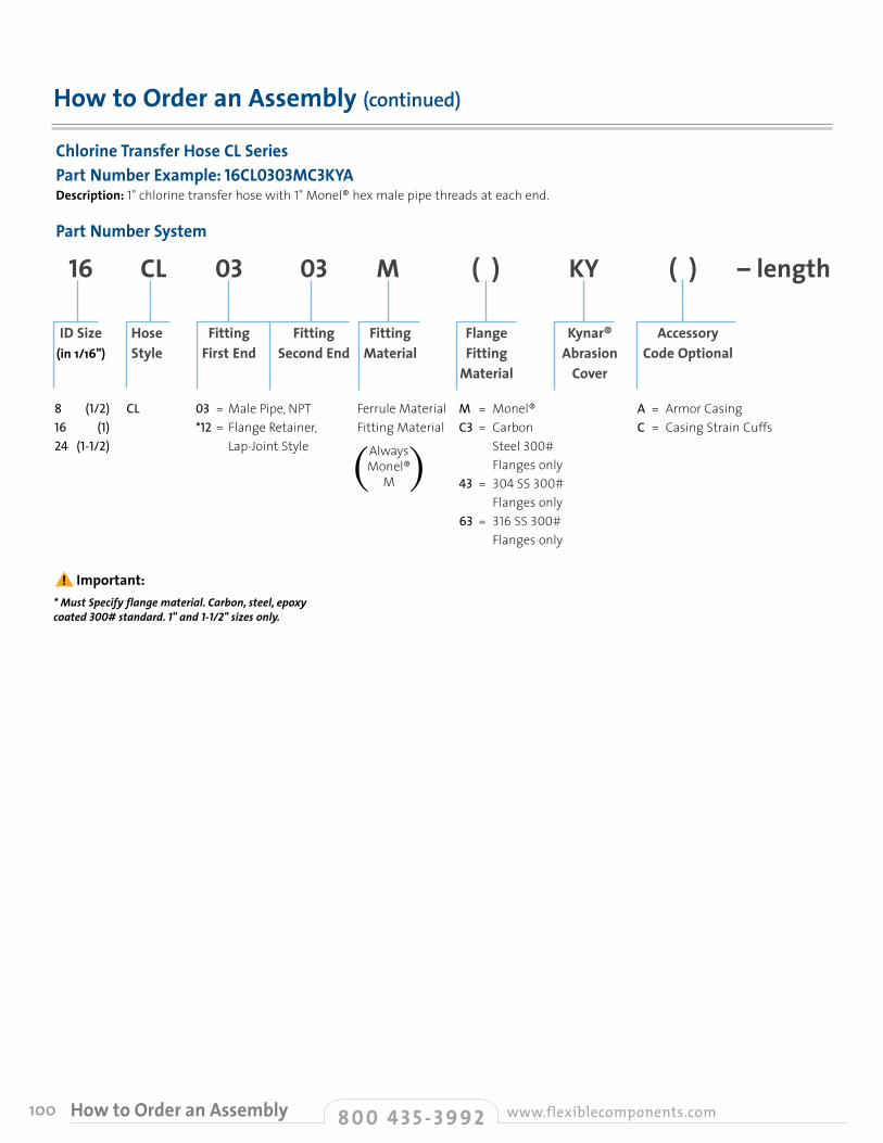
100
How to Order an Assembly (continued)
Chlorine Transfer Hose CL SeriesPart Number Example: 16CL0303MC3KYA Description: 1" chlorine transfer hose with 1" Monel® hex male pipe threads at each end.
Part Number System
16 CL 03 03 M ( ) KY ( ) – length
ID Size Hose Fitting Fitting Fitting Flange Kynar® Accessory (in 1/16") Style First End Second End Material Fitting Abrasion Code Optional Material Cover
8 (1/2)16 (1)24 (1-1/2)
CL 03 = Male Pipe, NPT *12= Flange Retainer, Lap-Joint Style
A = Armor CasingC = Casing Strain Cuffs
Ferrule Material Fitting Material
M = Monel® C3 = Carbon Steel 300# Flanges only 43 = 304 SS 300# Flanges only 63 = 316 SS 300# Flanges only
AlwaysMonel®
M( )
*MustSpecifyflangematerial.Carbon,steel,epoxycoated 300#standard.1"and1-1/2"sizesonly.
! Important:
8 0 0 4 3 5 - 3 9 9 2 www.flexiblecomponents.comHow to Order an Assembly
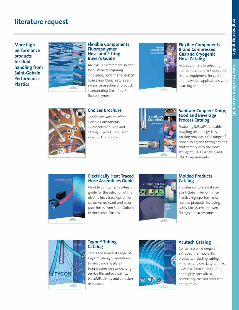
engineering guide how to order an assem
bly
literature request
More high performance products for fluid handling from Saint-Gobain Performance Plastics
Tygon® Tubing CatalogOffers the broadest range of Tygon® tubing formulations to meet such needs as temperature resistance, long service life, autoclavability, biocoMPatibility and abrasion resistance.
Flexible Components Fluoropolymer Hose and Fitting Buyer’s GuideAn invaluable reference source for customers requiring innovative, performance-tested hose assemblies. Features an extensive selection of products incorporating Chemfluor® fluoropolymers.
Choices BrochureCondensed version of the Flexible Components Fluoropolymer Hose and Fitting Buyer’s Guide. Useful as a quick reference.
Electrically Heat Traced Hose Assemblies GuideFlexible Components offers a guide for the selection of the electric heat trace option for corrosive-resistant and ultra pure hoses from Saint-Gobain Performance Plastics.
Flexible Components Brand Compressed Gas and Cryogenic Hose CatalogAids customers in selecting appropriate transfer hoses and related equipment for custom and individual applications with exacting requirements.
Sanitary Couplers Dairy, Food and Beverage Process CatalogFeaturing ReSeal®‚ re-usable coupling technology, this catalog provides a full range of hose, tubing and fitting options that comply with the most stringent 3-A, FDA/PMO, and USDA requirements.
Molded Products Catalog Provides complete data on Saint-Gobain Performance Plastics high-performance molded products, including tanks, biosystems, blowers, fittings and accessories.
Acutech Catalog Contains a wide range of extruded thermoplastic products, including tubing, pipe, rod and specialty profiles, as well as heat shrink tubing and highly specialized, proprietary custom products and profiles.
Saint-Gobain Performance Plastics460 Milltown RoadBridgewater, NJ 08807Tel: 1-800-435-3992Fax: 1-908-575-0459www.flexiblecomponents.com
FLS-3187-20M-0608-SGCS ©2008 Saint-Gobain Performance Plastics Corporation Printed in U.S.A
Saint-Gobain Performance PlasticsI-295 @ Harmony RoadMickleton, New Jersey 08056Tel: (800) 543-8823, (856) 423-6630 Fax: (856) 423-8182Roll Cover, Engineered Extrusions www.bunnell-plastics.com
Saint-Gobain Performance Plastics150 Dey RoadWayne, New Jersey 07470-4669Tel: (973) 696-4700 Fax: (973) 696-4056Chemware®
www.labpure.com
Saint-Gobain Performance Plastics700 Warner Blvd.Taunton, Massachusetts 02780Tel: (508) 823-7701 Fax: (508) 823-1438Specialty Extruded and Molded Silicone Products www.biopharm.saint-gobain.com www.medical.saint-gobain.com
Saint-Gobain Performance PlasticsLa Mothe-aux-AulnaiesF-89120 Charny FranceTel: (33) 3-86-63-78-78 Fax: (33) 3-86-63-77-77Silicone Products, Hose Assemblies www.verneret.com
Saint-Gobain Performance PlasticsP.O. Box 1344, 11 Sichio DrivePoestenkill, New York 12140Tel: (518) 283-5963 Fax: (518) 283-1418Specialty Closures www.labpure.com
Saint-Gobain Performance Plastics2316 West Wisconsin StreetPortage, Wisconsin 53901Tel: (800) 236-7600, (608) 742-8541 Fax: (608) 742-3179Specialty Molded Silicone Componentswww.medical.saint-gobain.com
Manufacturing FacilitiesSaint-Gobain Performance Plastics2664 Gilchrist RoadAkron, Ohio 44305Tel: (800) 798-1554, (330) 798-9240 Fax: (330) 798-6968Tygon® Brand Flexible Tubing, Chemfluor® Tubing www.tygon.com
Saint-Gobain Performance Plastics3910 Terry-Diane StreetBeaverton, Michigan 48612Tel: (888) 387-0067, (989) 435-9533 Fax: (989) 453-2355Tygon® Brand Extruded Silicone and Molded Components www.biopharm.saint-gobain.com www.medical.saint-gobain.com www.industrialsilicone.com
Saint-Gobain Performance Plastics460 Milltown RoadBridgewater, New Jersey 08807Tel: (800) 435-3992, (908) 218-8888 Fax: (908) 218-9009Flexible Components, Sanitary Couplers ReSeal® and PermaSeal®, Sani-Tech® Products, Tanks www.flexiblecomponents.com www.reseal.com
Sales OfficesSaint-Gobain Performance Plastics1468 Kun Yang RoadMinhang Economic & TechnologicalDevelopment Zone,Shanghai, China 200245Tel: (86) 21-5472-1568Fax: (86) 21-5472-2778/5472-2379
Saint-Gobain Performance Plastics19801-5, Haramura, Suwa-gunNagano 391-0100, JapanTel: (81) 266-79-6400Fax: (81) 266-70-1001
Saint-Gobain Performance Plastics13th Floor, Donghsin Building141-28, Samsung-DongKangnam-Ku Soeul, 135-090KoreaTel: (82) 2-501-7361Fax: (82) 2-554-1550
Saint-Gobain Performance PlasticsSuite 1203 147 Chienkwo North RoadSection 2, Taipei, 104 TaiwanTel: (886) 2-2503-4201Fax: (886) 2-2503-4202
Saint-Gobain Performance Plastics50, Jalan PJS 11/20, Bandar Sunway,46150 Petaling Jaya, Selangor DE,MalaysiaTel: (603) 56364082 Fax: (603) 56364099
Saint-Gobain Performance Plastics3-7, Kojimachi, Chiyoda-kuTokyo 102-0083, JapanTel: (81) 3-3263-0285Fax: (81) 3-3263-0286
Saint-Gobain Performance PlasticsGrindwell LtdVia Old Madras RoadBangalore 560 049, IndiaTel: (91) 80-847-2900Fax: (91) 80-847-2905
Saint-Gobain Performance Plastics 148 Newton RoadWetherill Park, NSW 2164 AustraliaTel: (61) 2-9749-3598 Fax: (61) 2-9643-2926
Saint-Gobain Performance Plastics Av Independicia 7031 13280-000 Vinhedo-SPBrazilTel: (55) 19-3876-8153 Fax: (55) 19-3876-8077
Limited Warranty: For a period of 6 months from the date of first sale, Saint-Gobain Performance Plastics Corporation warrants this product(s) to be free from defects in manufacturing. Our only obligation will be to provide replacement product for any portion proving defective, or at our option, to refund the purchase price thereof. User assumes all other risks, if any, including the risk of injury, loss or damage, whether direct or consequential, arising out of the use, misuse, or inability to use this product(s). SAINT-GOBAIN PERFORMANCE PLASTICS DISCLAIMS ANY AND ALL OTHER WARRANTIES, EXPRESSED OR IMPLIED, INCLUDING THE IMPLIED WARRANTIES OF MERCHANTABILITY AND FITNESS FOR A PARTICULAR PURPOSE.
NOTE: Saint-Gobain Performance Plastics Corporation does not assume any responsibility or liability for any advice furnished by it, or for the performance or results of any installation or use of the product(s) or of any final product into which the product(s) may be incorporated by the purchaser and/or user. The purchaser and/or user should perform its own tests to determine the suitability and fitness of the product(s) for the particular purpose desired in any given situation.
Tygon®, ReSeal®, Chemfluor®, Sani-Tech®, ReSeal®, PermaSeal®, Puregard®, Sanigard®, Cleargard®, Chemware®, FlexPro® and Swiv-L-Flex® are registered trademarks. PharmaSmooth™ is a registered trademark.Teflon® is a registered trademark of E.I. du Pont nemours and Company. Kynar® is a registered trademark of Arkema, Inc.
Monel® is a registered trademark of Special Metals Corp.Hastelloy® is a registered trademark of Haynes International, Inc.Viton® is a registered trademark of DuPont Performance Elastomers.
Notice:Due to our continuous efforts to improve our products, the information contained in this document is subject to change without notice. Saint-Gobain Performance Plastics assumes no obligations or liability for any advice furnished by it, or for results obtained with respect to those prod-ucts. All such advice is given and accepted at the buyers’ risk. Final determination of suitability of any information or product for the use to be contemplated is the sole responsibility of the user. This document contains proprietary information, which is protected by copyright, and may not be reproduced in any form without written consent of Saint-Gobain Performance Plastics.


