Download - Final Design Report - NASA


Final Design Report
on
Converting the Minuteman Missileinto a Small Satellite Launch System
Submitted to
Dr. George W. BotbylUSRA Design Professor
Department of Aerospace EngineeringThe University of Texas at Austin
by
The Minotaur Design Team
Rodrick McHaty - Team LeaderRodolfo Gonzalez - Chief Engineer
Vu Pham - Chief Administrative Officer
Engineers:Gordon MacKay
Greg HumbleBill Alexander
November 24, 1993


EXECUTIVE SUMMARY
m
Introduction
Due to the Strategic Arms Reduction
Talks (START) treaty between the United
States and Ex-Soviet Union, 450Stage III
Minuteman II (MMII) missiles were -qrecently taken out of service. Minotaur
Designs Incorporated (MDI) intends to StagelI
convert the MMII ballistic missile from a ""
nuclear" warhead carrier into a small- "] L__________
]satellite launcher. MDI will perform this
conversion by acquiring the Minuteman Stage Istages, purchasing currently available
control wafers, and designing a new
shroud and interfaces for the satellite.Figure 1. MDI missile
MDI is also responsible for properly
integrating all systems.The new MDI system still
System Description incorporates the original range-safetyraceway and attitude-control actuators.
MDI plans to purchase the 52 inchFigure 1 shows a representation of
diameter avionics, range-safety, andthe MDI missile. The stages that MDI
attitude-control wafers from Martinwill acquire from the Air Force are the
Marietta's Multi-Service Launch SystemMMII stage I and II, and the MMIII stage
(MSLS), "D" configuration missile,III. These stages define the propulsion
which is currently under development.system of the MDI missile, and an
MDI has designed a mechanicalanalysis of attainable orbits is performed.
interface to the payload, that uses fourThis analysis is also performed if the
truss elements and a Marmon clamp,satellite customer requires a STAR 17A
which can wrap around various satelliteor STAR 27 injection stage.
diameters (see Figures 2 and 3). The
support structure is able to support up to
1500 Ibm. The payload support bulkhead

has an allotted interface for any electrical California, and a secondary launch site is
connections the satellite requires. MDI also available at Cape Canaveral Air
has also sized a new shroud that fits Force Base in Florida. Combined, these
various small satellites and uses a two sites provide for a wide range of
thrusting-joint-separation mechanism, orbit inclinations (29° - 104°). Figure 4
displays attainable orbits when the missile
MarmonClampShearlip ;atellite is launched from VAFB with variousBand
ContinuityPlug injection stages at permissible orbitEED inclinations. As the figure indicates, the
PlungerMDI missile can launch payloads a big as
ReleaseSprings 1000 Ibm to circular orbits ranging from
100 to 2500 nautical miles (nm),Control BoxRelease
depending on orbit inclination and what
Free Set injection stage, if any, the customer
wishes to use. The expected launchDelay Set
• • environments (temperatures, pressures,+
Truss and vibrations) the satellite will be
PSBInterface ReleaseSpring exposed to during launch are carefully
Figure 2: Support Structure studied and taken into consideration in thedesign of the MDI launch vehicle.
Marmon
Clamp
_ qo L
{o looo 1_oo 2oo0 2_oo
od/t altitude[nm]
--- Figure 4: Attainable Orbits from
Figure 3: Payload Support VAFB
Bulkhead and Marmon Clamp
Mission ConceptsMDI Missile Performance
To stress the feasibility of its launch
The primary launch site is vehicle, MDI has performed two satellite
Vandenberg Air Force Base (VAFB) in mission designs as proof of concept. The

two payloads chosen are BATSAT and
the Asteroid Investigation
Microspacecraft (AIM). Each payload
has been properly interfaced with the
missile, and MDI shows how the orbit
needs are attainable with the launch
system.
Launch System Competitiveness
To show launch system
competitiveness, the MDI missile is
compared to other small satellite launch
systems (Scout and Pegasus). All
systems have comparable attainable
orbits, insertion errors, and usable
shroud volumes. However, the MDI
missile's launch costs ($7.5 million) are
considerably less than the other launch
systems ($12, $15 million)
TABLE OF CONTENTS
LIST OF FIGURES .................................................................................................. iii
LIST OF TABLES .................................................................................................... v
LIST OF ACRONYMS ........................................................................................... v i
ACKNOWLEDGMENTS ...................................................................................... v i i
1.0 INTRODUCTION ........................................................................................... 1
2.0 MISSION GOALS ............................................................................................ 3
3.0 SATELLITE SURVEY ..................................................................................... 4
4.0 SYSTEM DESCRIPTION ................................................................................ 6
4.1 Propulsion ............................................................................................ 74.2 Avionics ................................................................................................ 8
4.3 Attitude Control .................................................................................. 10
4.4 Range Safety ......................................................................................... 11
4.5 Support Structure ............................................................................... 12
4.5.1 Design Requirements and Strategy ........................................ 13
4.5.2 Support-Structure Design ........................................................ 144.6 Electrical Structure .............................................................................. 16
4.6.1 Design Requirements and Strategy ........................................ 16
4.6.2 Electrical-Structure Design ....................................................... 174.7 Shroud ................................................................................................... 18
4.7.1 Design Requirements and Strategy ........................................ 18
4.7.2 Shroud Design ............................................................................ 19
4.7.3 Separation Mechanisms ........................................................... 225.0 LAUNCH VEHICLE PERFORMANCE ...................................................... 24
5.1 Attainable Orbits ................................................................................. 24
5.2 Launch Profile ..................................................................................... 27
5.3 Expected Launch Environment ....................................................... 295.3.1 Thermal Environment ............................................................. 29
5.3.2 Pressure Environment ............................................................. 29
5.3.3 Dynamic Environment ............................................................ 30
6.0 .MISSION DESIGNS ........................................................................................ 32
6.1 BATSAT ................................................................................................ 32
6.2 AIM ........................................................................................................ 33
7.0 TIME LINE AND COST ANALYSIS ........................................................... 35

7.1 Research and Development ............................................................. 357.2 Launch Costs ........................................................................................ 36
7.3 Long-Term Profitability ..................................................................... 37
8.0 LAUNCH SYSTEM COMPETITIVENESS ................................................. 39
8.1 Attainable-Orbits Comparison ......................................................... 39
8.2 Insertion Errors ................................................................................... 39
8.3 Shroud-Size Comparison .................................................................. 40
8.4 Cost Comparison ................................................................................. 41
9.0 MANAGEMENT STATUS ........................................................................... 42
9.1 Management Goals ............................................................................. 42
9.2 Program Organization ....................................................................... 42
9.3 Program Control and Schedule ....................................................... 439.4 Workload Distribution ...................................................................... 43
9.5 Project Level of Effort ......................................................................... 44REFERENCES ......................................................................................................... 49
CONTACTS ............................................................................................................. 50
APPENDIX A Prospective Satellite Data .......................................................... A-1
APPENDIX B Launch-Performance Analysis ................................................. B-1
APPENDIX C Finite-Element Model Specifications ...................................... C-1
C.1 Payload-Support Bulkhead .............................................................. C-1C.2 Truss Elements ................................................................................... C-2
C.3 Shroud .................................................................................................. C-3
APPENDIX D Payload User's Guide .................................................................. D-1D.1 Attainable Orbits ................................................................................ D-1
D.2 Mechanical Interfaces ........................................................................ D-2
D.3 Launch Time and Costs .................................................................... D-3
D.4 Expected Launch Environment ...................................................... D-4
ii

LIST OF FIGURES
Figure 1.1 MSLS configurations ................................................................ 1
Figure 1.2 Launch Performance for the MSLS Rocket configurations ..................... 2
Figure 1.3 Design-process diagram ............................................................. 3
Figure 3.1 Diameters for various satellites ..................................................... 4
Figure 3.2 Heights for various satellites ....................................................... 5
Figure 3.3 Weights for various satellites ....................................................... 5
Figure 4.1 MDI missile systems ................................................................ 6
Figure 4.2 Propulsion system ................................................................... 8
Figure 4.3 Avionics wafer ....................................................................... 9
Figure 4.4 Actuator locations .................................................................... 10
Figure 4.5 Cut-away of TVC actuator ....................................................... i.. 11
Figure 4.6 Range-Safety System ................................................................ 12
Figure 4.7 Support structure ..................................................................... 13
Figure 4.8 Payload-support bulkhead .......................................................... 14
Figure 4.9 Tubular truss structure .............................................................. 15
Figure 4.10 Payload-Attach Fitting with injection stage ...................................... 16
Figure 4.11 Electrical structure .................................................................. 17
Figure 4.12 Missile shroud ...................................................................... 18
Figure 4.13 MDI shroud ......................................................................... 19
Figure 4.14 MSLS & MDI shroud dimensions ............................................... 20
Figure 4.15 Shroud Design Space Chart ....................................................... 21
Figure 4.16 Horizontal-Separation System (HSS) ........................................... 22
Figure 4.17 Vertical-Separation System ........................................................ 23
Figure 5.1 Launch vehicle performance at VAFB ............................................. 24
Figure 5.2 Launch vehicle performance at Cape Canaveral .................................. 25
°°°
111
Figure 5.3 VAFB restricted launch angles .................................................... 25
Figure 5.4 Cape Canaveral restricted launch angles .......................................... 26
Figure 5.5 Launch sequence of events ......................................................... 28
Figure 5.6 Thermal environment ................................................................ 29
Figure 5.7 Pressure environment ............................................................... 30
Figure 5.8 Random vibration environment .................................................... 30
Figure 5.9 Shock environment .................................................................. 31
Figure 6.1 BAT ............................ . ...................................................... 32
Figure 6.2 BATSAT Orbit Requirement and MDI Vehicle Capabilities .................... 33
Figure 6.3 AIM mounted in MDI missile ...................................................... 34
Figure 6.4 AIM orbit requirement and MDI missile capabilities ............................. 34
Figure 7.1 Research and development timeline ................................................ 36
Figure 7.2 Launch timeline ...................................................................... 37
Figure 7.3 MDI projected net worth ............................................................ 38
Figure 8.1 MDI missile, Scout, Pegasus attainable orbits ................................... 39
Figure 8.2 Relative shroud volumes ............................................................ 40
Figure 9.0 Group level of effort ................................................................. 44
Figure 9.1 Minotaur team organization ......................................................... 45
Figure 9.2 MDI Pert chart ........................................................................ 46
Figure 9.3 MDI GANT chart .................................................................... 47
iv

LIST OF TABLES
Table 4.1 Rocket stage properties ............................................................... 8
Table 4.2 PSB structural properties ............................................................. 14
Table 4.3 Single truss element properties ...................................................... 15
Table 5.1 Pre-launch sequence .................................................................. 27
Table 5.2 Launch sequence of events ........................................................... 28
Table 7.1 Research and Development Costs ................................................... 35
Table 7.2 Launch costs ........................................................................... 37
Table 8.1 MDI missile, Scout, Pegasus injection errors ..................................... 40
Table 8.2 Usable shroud volumes .............................................................. 40
Table 8.3 Launch cost comparison .............................................................. 41
V

LIST OF ACRONYMS
ACS Attitude Control
AFB Air Force Base
AIM Asteroid Investigation Microspacecraft
ARSS Airborne Range Safety System
EED Electrical Explosive Device
GPS Global Positioning System
GNC Guidance, Navigation and Control
HS S Horizontal Separation System
ICBM Inter Continental Ballistic Missile
IMU Inertial Measurement Unit
MDI Minotaur Designs Incorporated
MGS Missile Guidance Set
MMII Minuteman 17ICBM
MMII/ Minuteman m ICBM
MSLS Multi-Service Launch System
PAF Payload Attach Fitting
PSB Payload Support Bulkhead
PSD Power Spectral Density
RF Radio Frequency
R&D Research and Development
RSLP Re-entry System Launch Program
START Strategic Arms Reduction TalksTVC Thrust Vector Control
USRA Universities Space Research Association
VAFB Vandenberg Air Force Base
VSS Vertical Separation System
vi

ACKNOWLEDGMENTS
The Minotaur Design team would like to thank all the personnel who aided us in our
design, and more specifically:
NASA/USRA Advanced Design Program
Jet Propulsion Laboratory
Steve Johnson
Martin Marietta
Pat Albert
David Steel
TRACOR AEROSPACE
Ronda Foster
Les Richards
David Schorr
Texas Space Grant Consortium
Jim Wilson
United States Air Force
Captain Ron Ostroff
Universities Space Research Association
Dr. Coleman
Jack Sevier
Universi .tyof Texas
Dr. George W. Botbyl
Dr. Wallace. T. Fowler
George Hindman
Elfego Pifion
Scott Striepe
vii

1.0 INTRODUCTION
With the continuing decrease in funding for space-exploration projects, a greater need
for cost-effective launch systems has developed. Recently, 450 Minuteman II (MMII)
Intercontinental Ballistic Missiles (ICBM) have been taken out of service as part of the
Strategic Arms Reduction Talks (START) peace treaties between the United States and the
Ex-Soviet Union [1]. Consequently, converting these missiles from warhead to satellite
launchers may provide a cost-effective method for future payload launches.
Two existing programs already make use of MMII stages: the Re-entry Launch System
Program (RLSP) and the Multi-Service Launch System (MSLS). The RLSP uses MMIII
stages to propel research payloads to sub-orbital trajectories. The MSLS, which is being
developed by Martin Marietta, consists of several rocket configurations (A, B, C, and D)
that use variations of MMII and MMIII stages. These configurations are displayed in
Figure 1.1. Martin Marietta has also computed the expected launch performance for each
rocket configuration, and this data is shown in Figure 1.2 [2].
A ShroudShroud D = 54"
_ Shroud /_ / Shroud -- O = 40" ---- D = 40" Front Section
D = 40" -- m D = 52"-- Front Section _ Front Section -- --New Sep Joint/Front Section -- D = 37.5"
_D = 37.5" -- D = 37.5"-- _ MMIII ---- New Interstage = --New Interstage
Stage 3 Stage 3 MMII_ MMIIIMMII
= J - stage 3 _ Stage 3
MMII _ MMII MMII MMII
Stage 2 _ f Stage 2 Stage 2 Stage 2
MMII MMII MMII. MMIIStage 1 Stage 1 _tage 1 Stage 1
r-,r r',t
A B C D
Figure 1.1 MSLS configurations

1200
1000
i 800 D6O0
4oo_ B
200 _
_ I I n i I I i I i I I I I I I I l I I I I I Ii a I i i
0 100 200 300 400 500 600
Orbit Altitude (nm)
Figure 1.2 Launch Performance for the MSLS Rocket configurations
The Universities Space Research Association (USRA) has taken special interest in
converting the MMII rocket into one that can deploy small satellites into orbit. Minotaur
Designs Inc.'s (MDI) objective is to produce such a satellite launch system by making use
of available MMII systems.
Figure 1.3 shows the design-process that MDI followed to meet its design objective.
As the figure indicates, several inputs were considered, such as the mission requirements,
the existing satellite market needs, and the expected launch environments. A conceptual
design was analyzed and sized through a series of trade studies, which developed into
MDI's current preliminary design. To prove system competitiveness, MDI compared its
launch vehicle to other small-satellite launch vehicles such as the Pegasus and the Scout. In
addition, MDI decided to show a proof of concept by designing two specific satellite
mission concepts. The second half of the diagram indicates the future work needed to meet
the end goal of a building reliable launch vehicle.
2

Cost
StrategyC°rp°rate_ Analisis
] Survey Satellite t _ Conceptual _ Trade Studies, _ Compareto
• Market Design Design Analysis, _ Other Launch
Systems Integration - [ Systems
xpctLaunch Environment
IPreliminaryDesign ] I_ Concept [
V
IPr°vide' Fabricate' _ _ Final Design I
Test, and Integrate AnalysisComponents
Re-design
[ Final Design _----_ Satellite _ Post_flight Analysis _-_ Reliable Satellite [Mission/Launch ' - [Launch System
I Satellite Customer I
Figure 1.3 Design-process diagram
2.0 MISSION GOALS
MDI's goal is to produce a launch system design that incorporates available MMII
systems. The system uses launch pads at Vandenberg AFB as the primary launch site but
also can use Cape Canaveral as a secondary launch location. MDI also analyzes the
performance gained by using an injection stage to provide a wider range of orbits. Satellite
interfaces must be interchangeable and modular so that a variety of satellites can be housed.
The launch system should be reliable, competitive, and oriented to the satellite customer.
In addition, MDI requires that the launch system be a profitable venture.

3.0 SATELLITE SURVEY
MDI surveyed a number of potential satellite customers. The results of those surveys
are included in Appendix A. All of the satellites surveyed fall within the structural and
dimensional limits of the MDI design and are launchable with the MDI missile. All of these
satellites are viewed as tentative systems for MDI launch. The specific diameters, heights
and weights are shown in Figures 3.1 through 3.3.
44
45 4040 38 38 38
35
,.., 30 26 25 24
2o10
5
0 I I I I I I I I I
<
Figure 3.1 Diameters for various satellites.

l_ qel°a_qAI _
• _" IVSIV8
it3
±vsxv_ ..*_ _ _ ..*'_-" _ SIXH"IV ,.-"
009 8V __I r_
,_ SIX_I"IV m
,,-> IAIIV ..=
| a..1 *_
_ s_eslq3!l_" 009 8Vt,-,.
_13_I _.
' = " ! _]IA[:)V =,m ,,mr
r-- I ,_IIAI_)V ..............................I i I i l I
_,,,,: .... :.... :.... :.... :.... :.... :.... : _ _ _ _ _ _
(u!) _q3!_H (sql) _q3!o_A

4.0 SYSTEM DESCRIPTION
MDI will acquire MMII stages I and II, MMIII stage III from the U.S. Air Force, and
purchase STAR 17A or STAR 27 injection stages from Thiokol. MDI will also purchase
previously designed control wafers, all of which are currently available in the market.
Furthermore, MDI will also design a missile-to-satellite mechanical and electrical interface
as well as a shroud; these designs will then be sub-contracted out in order to minimize cost.
MDI will be responsible for the overall integration of all the missile systems. Figure 4.1
shows tiae launch system components.
Stage IIIShroud
10 feet
StageII
1 --Avionics
Stage I FrontSection ACS 6feet
_ ARSS ___
Figure 4.1 MDI missile systems
The Minuteman stages will come with attitude-control actuators that the MDI avionics
wafer will command. MDI will also use the range-safety raceway that was originally built
with the stages. The MSLS, "D" configuration avionics wafer, attitude-control wafer, and
range-safety wafer will be purchased from Martin Marietta. MDI has designed a Marmon
clamp, which uses 4 truss elements to connect the payload to the missile. The structure can
support a payload of 1500 lbm during the launch. Upon orbit insertion, this mechanical
6
interface will release the satellite. MDI also designed a shroud that uses a thrusting-joint-
separation system. All systems are discussed in more detail in the following sections.
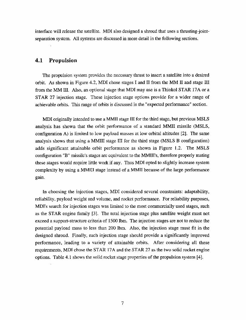
4.1 Propulsion
The propulsion system provides the necessary thrust to insert a satellite into a desired
orbit. As shown in Figure 4.2, MDI chose stages I and II from the MM II and stage III
from the MM III. Also, an optional stage that MDI may use is a Thiokol STAR 17A or a
STAR 27 injection stage. These injection stage options provide for a wider range of
achievable orbits. This range of orbits is discussed in the "expected performance" section.
MDI originally intended to use a MMII stage 111for the third stage, but previous MSLS
analysis has shown that the orbit performance of a standard MMII missile (MSLS,
configuration A) is limited to low payload masses at low orbital altitudes [2]. The same
analysis shows that using a MMIII stage IN for the third stage (MSLS B configuration)
adds significant attainable orbit performance as shown in Figure 1.2. The MSLS
configuration "B" missile's stages are equivalent to the MMHI's, therefore properly mating
these stages would require little work if any. Thus MDI opted to slightly increase system
complexity by using a MMIII stage instead of a MMII because of the large performance
gain.
In choosing the injection stages, MDI considered several constraints: adaptability,
reliability, payload weight and volume, and rocket performance. For reliability purposes,
MDrs search for injection stages was limited to the most commercially used stages, such
as the STAR engine family [3]. The total injection stage plus satellite weight must not
exceed a support-structure criteria of 1500 Ibm. The injection stages are not to reduce the
potential payload mass to less than 200 ibm. Also, the injection stage must fit in the
designed shroud. Finally, each injection stage should provide a significantly improved
performance, leading to a variety of attainable orbits. After considering all these
requirements, MDI chose the STAR 17A and the STAR 27 as the two solid rocket engine
options. Table 4.1 shows the solid rocket stage properties of the propulsion system [4].

i StarInjectionStage
_ MMIIIStage III
MMIIStage II
MMIIStage I
Figure 4.2 Propulsion system
Table 4.1 Rocket stage properties
MASS
STAGE Isp (sec) Dry (Ibm) Propellant (Ibm)
I 268 4680 45730
II 287 1753 13720
III 285 744 7289
STAR 27 286 53 741
STAR 17A 280 30 246
4.2 Avionics
The missile's avionics wafer is responsible for Guidance, Navigation and Control
(GNC). GNC consists of computing and controlling the missile's state (position, velocity,
attitude; and attitude rates). This wafer sits highest on the front section, as shown in
Figure 4.3. The avionics wafer holds the IMU and flight computer. In addition to housing
8
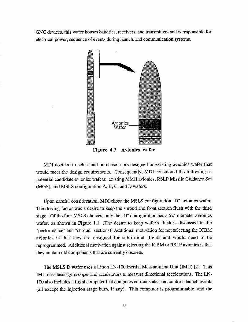
GNC devices, this wafer houses batteries, receivers, and transmitters and is responsible for
electrical power, sequence of events during launch, and communication systems.
AvionicsWafer
Figure 4.3 Avionics wafer
MDI decided to select and purchase a pre-designed or existing avionics wafer that
would meet the design requirements. Consequently, MDI considered the following as
potential candidate avionics wafers: existing MMII avionics, RSLP Missile Guidance Set
(MGS), and MSLS configuration A, B, C, and D wafers.
Upon careful consideration, MDI chose the MSLS configuration "D" avionics wafer.
The driving factor was a desire to keep the shroud and front section flush with the third
stage. Of the four MSLS choices, only the "D" configuration has a 52" diameter avionics
wafer, as shown in Figure 1.1. (The desire to keep wafer's flush is discussed in the
"performance" and "shroud" sections) Additional motivation for not selecting the ICBM
avionics is that they are designed for sub-orbital flights and would need to be
reprogrammed. Additional motivation against selecting the ICBM or RSLP avionics is that
they contain old components that are currently obsolete.
The MSLS D wafer uses a Litton LN-100 Inertial Measurement Unit (IMU) [2]. This
IMU uses laser-gyroscopes and accelerators to measure directional accelerations. The LN-
100 also includes a flight computer that computes current states and controls launch events
(all except the injection stage burn, if any). This computer is programmable, and the

launch profile can be modified depending on the mission [5]. The transmitters and
receivers are used to communicate with the ground and to relay data regarding the launch.
During launch, antennas have line-of-site view with the ground and are attached flush withthe outside surface of the wafer.
4.3 Attitude Control
For all phases of the launch, the attitude-control system must maintain the properorientation of the missile to ensure accurate orbit insertion. The avionics wafer will be
responsible for issuing commands to the attitude-control actuators up to the time of the
payload separation, and an injection stage will need its own logic to control its proper
attitude.
During first-stage flight, the first stage will use differential gimballing of the four
nozzles to control roll, and engine gimballing to control pitch and yaw. During second and
third-stage flight, the respective stage will use nozzle gimballing to control pitch and yaw,
and four tangential thrusters to control roll. For any necessary coasting phases (described
in the "performance" section), an attitude-control system (ACS) wafer will maintain proper
orientation. This ACS wafer will use four radial thrusters for pitch and yaw and four
tangential thrusters for roll. Figure 4.4 shows the actuator locations.
__ _ ACS Wafer
Roll Thrusters _"Gimballed
Nozzles
Figure 4.4 Actuator locations
10

The minuteman stages contain the attitude-control actuators with which the stages were
originally designed. Since they are robust enough to control a sub-orbital ICBM trajectory,
they should be adequate for MDI's purposes. The ACS wafer will be purchased from
Martin Marietta's MSLS program, and as mentioned before, a "D" Configuration wafer
will be used to keep the Front section flush with the rocket stage. This MSLS ACS wafer
uses cold nitrogen gas to provide the necessary thrusts.
If an injection stage is used, it will also need some form of attitude control. Since it can
not receive commands from the avionics wafer, the satellite will have to control the
injection stage. Therefore, the satellite customer will be required to purchase and provide
command controls for the injection stage. The STAR injection engine will have Thrust
Vector Control (TVC), which will use engine gimballing to control pitch and yaw. The
TVC actuator used to bend the flexible nozzle is shown in Figure 4.5.
Figure 4.5 Cut-away of TVC actuator
4.4 Range Safety
In the event of a hazardous situation, ground control must be able to destroy the launch
vehicle. The Airborne Range Safety System (ARSS) wafer provides the solution for this
need. The ARSS uses range transponders, control logic, and a raceway that detonates the
stages in case of a major malfunction.
11

The range transponders are used so that ground stations can track the missile
independently of the avionics wafer's computed state. If these transponders fail, a skin
track can still be performed. A command logic that resides in this wafer issues a destruct
command that will detonate the raceway's explosives in the stage casings (see Figure 4.6).
The stages will be purchased with the originally designed missile raceway. The MSLS,
configuration "D", ARSS wafer will be purchased, and MDI will make sure the wafer is
properly mated with the raceway. The MSLS ARSS wafer is designed with redundancy to
ensure safety. Each system has a one-fault tolerance. Again, configuration "D" wafers
were chosen so that the front section and shroud would be flush. This wafer will be
discarded with the third stage when it has outlived its purpose.
Raceway
ARSSWafer
Figure 4.6 Range Safety System
4.5 Support Structure
MDI designed the support structure (shown in Figure 4.7) that attaches the payload to
the missile. This support structure is composed of a Payload Support Bulkhead (PSB) and
four trusses. The PSB is a standardized structure that can support four trusses. These
trusses transfer the satellite loads during launch and are configurable for any size payload
12
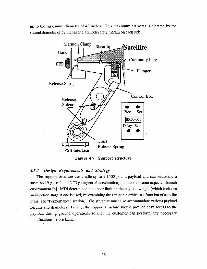
up to the maximum diameter of 48 inches. This maximum diameter is dictated by the
shroud diameter of 52 inches and a 2 inch safety margin on each side.
Marmon Clamp Shear lip ;atelliteBand
Continuity PlugEED
Plunger
Release Springs
Control BoxRelease
Solenoids • •Free Set
]00:00:00 ]Delay Set
+
Truss
Release SpringPSB Interface
Figure 4.7 Support structure
4.5.1 Design Requirements and Strategy
The support structure can cradle up to a 1500 pound payload and can withstand a
sustained 9 g axial and 3.75 g tangential acceleration, the most extreme expected launch
environment [6]. MDI determined the upper limit on the payload weight (which includes
an injection stage if one is used) by examining the attainable orbits as a function of satellite
mass (see "Performance" section). The structure must also accommodate various payload
heights and diameters. Finally, the support structure should provide easy access to the
payload during ground operations so that the customer can perform any necessarymodifications before launch.
13

4.5.2 Support Structure Design
The support structure consists of a payload-support bulkhead (PSB) mounted on top of
the avionics section, four truss elements mounted on the PSB, and a Marmon clamp that
connects to the payload.
The PSB, seen in Figure 4.8, is based on the RSLP bulkhead and is designed to mount
a variety of load-bearing structures and support the payload electrical interface. Each circle
represents a connection point that consists of 5 slots. Each truss is bolted through the
slots, and each connection point has a total tension pull-out capability of 15,000 Ibm [6, 3-
11]. The triangular object represents the electrical- interface connector, but the actual
connection point is circular to minimize stress concentrations.
ElectricalConnector
TopView
17A
Star 27
Figure 4.8 Payload support bulkhead
Table 4.2 PSB structural properties
Material Aluminum 7075
Finish Alodine 600
Thickness 2.0 inches
Weight 25 lbm
Truss Tension Pullout Capability 15,000 lbm per truss
14

Additional load-bearing structures consist of truss elements connected to the central
clamp. The structure is shown in Figure 4.9, and truss properties are shown in Table 4.3.
Each truss element consists of a rod, a clamping end, and two hinges. These hinges can be
set to properly fit various payloads. Upon payload separation, the rod elements rotate
outward to prevent contact with the payload.
Marmon
Clamp
Figure 4.9 Tubular truss structure
Table 4.3 Single truss element properties
Material Steel
Young's Modulus 30,000 psi
Poisson's Ratio 0.24
Cross Sectional Area 1.00 in
Length 36.00 in
Weight 8 lbm.
The trusses are connected to a payload lip with four wedges and a cinching ring, as seen
in Figure 4.7. When a separation discrete is issued, the Electrical Explosive Device (EED)
cuts the cinching ring; springs eject the wedges radially, and other springs eject the
payload: The clamp is designed with redundant separation initiators that send signals to the
EED.
In the case when the satellite needs an injection stage, MDI can provide a payload-attach
fitting (PAF). The MDI PAF design uses the same truss element as the support structure
does, except two clamping ends are attached to each side of a rod. These clamping ends
are attached to the injection stage and satellite as shown in Figure 4.10. If the satellite
needs to separate from the injection stage, a Marmon clamp with an EED will be used for
15

the upper attachment, while a permanent clamp will be used for the lower. If the satellite
does not need to separate from the injection stage, the two PAF clamps will be permanent.
_atellite
PayloadAttachFitting
Injection8_age
Figure 4.10 Payload-Attach Fitting (PAF) with injection stage
4.6 Electrical Structure
The electrical structure connects all the electrical systems. MDI has designed a wiring
harness that connects all required and optional electrical systems. MDI has also defined the
satellite interface, the flight data sensor connection and the missile interface.
4.6.1 Design Requirements and Strategy
The electrical structure is required to interface the system components, relay
information to ground control, initiate separation mechanisms and confirm separation. The
electrical structure is also required to determine the missile attitude and to control the state
vector.
MDI has decided that the electrical structure will not be mission specific; therefore MDI
has defined a wiring harness that connects all conceived electrical systems. Refitting the
wiring harness for mission specific requirements would be the satellite customer's
responsibility.
16

4.6.2 Electrical Structure Design
The control-block diagram shown in Figure 4.11 shows the components that are
supported by the electrical structure. The flight computer is housed with the IMU inside
the avionics wafer. This computer is programmable to accommodate different launch
profiles.[5]
,Telemetry Command I
I [ Modulat on I tec "
I
Rocket Stage I] _ _ sepH°rari6_:stalystem I
tComputer
- -- .__...._ PayloadSeparationSystem I
t ko, i PaYl°ed I• Differential Gimbaled nozzles
• Thrusters I FlightData (IMU, etc.)
_-----q Temperature ISensors I
Figure 4.11 Electrical structure
As Figure 4.11 shows, the computer receives data from the IMU's accelerometers,
which is housed in the same wafer. The computer electrically interfaces with all the
missile's attitude actuators across the stage separation planes. There are also electrical
interfaces between the computer and telemetry, and between the range safety wafer and
raceway. All the previously mentioned electrical interfaces are under the avionics wafer
and have been designed by Martin Marietta.
There are also electrical interfaces from the avionics through the bulkhead. The
shroud's thrusting-joint horizontal and vertical separation systems are commanded to
separate by the avionics wafer. In addition, flight data from a series of transponders
(vibration, acoustic, temperature, pressure) housed in the shroud are sent through the
17

avionics wafer to the ground. Finally, a payload-separation discrete is sent through the
bulkhead and causes the clamp to release the satellite or injection stage.
4.7 Shroud
The shroud shown in Figure 4.12 covers the payload and protects it during the
atmospfieric portion of the flight. The shroud is an expendable structure and is jettisoned
after the missile leaves the atmosphere.
Shroud
I_
Figure 4.12 Missile shroud
4.7.1 "Design Requirements and Strategy
The first requirement for the shroud is to be Radio Frequency (RF) transparent so that
satellite vendors can communicate with their payloads at any time during the launch if
necessary. Also, the shroud must allow easy access to the payload so that vendors can
access their payload easily once the shroud is on. Next, the shroud-separation mechanism
must be designed so that minimal shock is imparted to the payload during shroud
separation in order to protect the payload. Finally, the shroud should be lightweight and
have a simple, redundant mechanism for separation.
As for the design strategy, MDI has taken the initiative to use new technology to design
the shroud. The design of the shroud relies on maximizing the usable volume of the
payload and minimizing the shroud weight. In addition, the larger diameter of the shroud
increases the number of potential satellite customers.
18

4.7.2 Shroud Design
The MDI shroud is a fiberglass composite two-part structure as shown in Figure 4.13.
The composition of the shroud makes it RF transparent. The shroud uses a doubly
redundant thrusting-joint separation mechanism with a Horizontal-Separation System
(HSS) and a Vertical-Separation System (VSS).
VSS
HSS
Figure 4.13 MDI shroud
The basis for the MDI shroud design is the MSLS shroud that has a 40 in. outside
diameter and a 150 in. height as shown in Figure 4.14. The goals of the MDI shroud are to
have comparable drag and weight, as well as a more efficient use of volume than the MSLS
shroud.
19

150irt1,q3in
MSLS M i no tau r
y
r" 52ia : 52in
Figure 4.14 MSLS & MDI shroud dimensions
As shown in Figure 4.14, the MDI shroud diameter is 52 in. There are two reasons for
using a. 52 in. diameter shroud. First, a 52 in. shroud allows the shroud and wafer
sections to remain flush with the MMIII third stage, which eliminates the need for a
connecting skirt that would increase the drag on the missile. Also, a 52 in. shroud allows
MDI to attract a larger portion of the satellite market as shown in the satellite survey (most
of the satellites surveyed have diameters between 40 in. and 52 in). Although the MDI
shroud has more surface area, the MSLS and MDI shrouds have a similar amount of drag
due to the fact that the MSLS shroud has a connecting skirt [6].
Another goal of the MDI shroud design is to have a weight comparable to the MSLS
configuration. The MSLS shroud weighs 240 Ibm. and uses a hinge-and-thrusters
separation mechanism. In an attempt to reduce the weight of the shroud, MDI discovered a
lightweight thrusting-joint separation system developed by TRACOR Aerospace. Through
data provided by TRACOR, MDI determined that a shroud with MSLS dimensions that
uses a thrusting-joint would weight 215 ibm. Therefore, MDI has decided to use the
thrusting-joint separation system in order to save weight.
2O

The final goal of the shroud design is to have a more efficient use of volume than the
MSLS shroud. The MSLS is 150 in. high with a usable inside-volume height of 111 in.
However, since the satellite survey implies that none of the potential satellites is higher than
76 in, then the MSLS shroud would contain up to 35 in. of unused volume for each launch
[7]. The MDI shroud design eliminates some of the unused volume inside the shroud. The
MDI shroud height is chosen from a plot of total shroud weight against shroud diameter for
varying heights, which is shown in Figure 4.15. A shroud weight of 215 lbm. and a
diameter of 52 in. would give a shroud height of 120 in., which would have a usable
volume height of 90 in. A 90 in. usable volume height would still house all of our potential
satellites. Thus, in addition to minimizing unused volume, the MDI shroud would weigh
less and can house more potential satellites than the MSLS configuration.
26o
240 -" h = 88 in
220 _ h = 100 in
o_ 180 _h=124in
_ 160
A h = 150 in140 ' '
39 44 49 54
Diameter (in)
Figure 4.15 Shroud Design Space Chart
21

4.7.3 Separation Mechanisms
Two thrusting-joint separation mechanisms are employed to jettison the shroud; a
Vertical Separation System (VSS) and a Horizontal Separation System (HSS). The
separation systems use linear charges that are fired by electrical explosive devices (EED's).
Two EED's exist at either end of the linear charge. The EED's are fired simultaneously on
each charge. The HSS is fired 20 milliseconds before the VSS. During jettison, the
thrusting-joint separation mechanism imparts a lower shock to the payload than a hinge-
and-thrusters separation system. Also, the thrusting-joint system is a simple, one-step
separation system that is more reliable and has fewer components than a hinge-and-
thrusters separation system [7].
The HSS employs a heavy-rail thrusting-joint and a linear charge with dual EED's as
shown in Figure 4.16 The VSS uses a light-rail thrusting joint and a linear charge with
dual EED's as shown in Figure 4.17 [8]. For both thrusting joints, the explosive chord
inflates the bellows, forcing the ends of the joint apart. The separation force is sufficient to
shear the rivets holding the joint together. The force can impart a separation velocity of 600
mph to the shroud [6].
Attenuator Tubes Rivet (TYP)
Linear Explosive _ _J
'Li}ll_x_C "( x ruslon) Linear PistonFlexible Bellows (Extrusion)
Figure 4.16 Horizontal Separation System (HSS) [8]
Courtesy of TRACOR Aerospace
22

,---_[___- \xL\ \\\ \\n"_._ ,--,
Installed
Separated
Figure 4.17 Vertical Separation System [8]
Courtesy of TRACOR Aerospace
23

5.0 LAUNCH VEHICLE PERFORMANCE
5.1 Attainable Orbits
A satellite vendor's primary concern for any launch vehicle is what payload masses can
be taken to the desired orbits. The MDI team has performed a preliminary analysis of the
MDI launch vehicle to determine the attainable orbits as a function of payload mass. This
final orbit altitude is a function of launch location, rocket configuration, payload mass and
orbit inclination.
In order to satisfy the wide range of the satellite market, MDI has performed this orbit
analysis for VAFB and Cape Canaveral launch sites [9]. In addition, the analysis has been
extended to cover payloads with no injection stage, STAR 17A injection stage and STAR
27 injection stage. Details of MDI's analysis are shown in Appendix B
Figures 5.1 and 5.2 summarize the results of MDI's analysis. Figures 5.3 and 5.4
show the restricted launch azimuths for VAFB and Cape Canaveral launch sites. These
launch azimuths are restricted for range-safety reasons, and these restrictions bound the
range of attainable orbit inclinations.
1200-
1000,_, 800, _::_ii..........
i 600 "_i""_ N_
400,I
2oo: _'_' ___::_::_::_::;_;_;_::_:;_::_::_::_il_°..:':_
0, _f_i_ ,,'.-'_-"_::i_ ................
0 500 1000 1500 2(300 2500
orbit altitude [nm]
Figure 5.1 Launch vehicle performance at VAFB.
24

1000- tal A
'W 8oo-I
600- :_,, __i_!_i®_,.. o
•"_ 400-
200-
0 500 1000 1500 2000 2500
orbit altitude [nm]
Figure 5.2 Launch vehicle performance at Cape Canaveral.
38"
36 °
Allowable
Latitude (ON) 34 °
OrbitInclination
32 °
L tehAzimuth
30124° 122 ° 120 ° 118 ° 116 °
Longitude (°W)
Figure 5.3 VAFB restricted launch angles [8]
25

32°
Orbit
30°
Latitude (ON) 28°
26 °
24 °84° 82° 80° 78° 76 °
Longitude (*W)
Figure 5.4 Cape Canaveral restricted launch angles [8]
Figures 5.1 and 5.2 show the attainable orbits of MDI's rocket system launched from
VAFB and Cape Canaveral, respectively. The figures depict payload mass as a function of
circular orbit altitude for 3 rocket configurations:
• No injection stage
• STAR 17A injection stage
• STAR 27 injection stage
As expected, the attainable orbit altitude decreases as the payload mass increases. Also,
high orbit inclinations result in lower performance (a decrease in orbit altitude). As the
orbit inclination decreases, the launch system's performance increases because of the
additional boost from the Earth's angular velocity.
As shown in Figures 5.1 and 5.2, a STAR 17A increases the performance by carrying
heavier payloads to higher altitudes. The STAR 27 increases attainable orbit altitudes even
more, but the upper mass is bounded at 700 ibm. The payload mass is limited for the
STAR 27 because the mass of this injection stage, combined with the mass of the satellite,
exceeds the permissible structural support criteria of 1500 Ibm.
In addition to attainable orbits, the satellite customer must know the expected orbit-
insertion errors for MDI's launch vehicle. Based on previous MSLS analysis of the "B"
configuration missile, MDI made the following insertion-error estimates for the final orbit:
26

• + 15 NM in orbit altitude
• + 0.5 o in orbit inclination. [10]
If the desired orbit is within MDI's launch-system capability, the excess performance
must be, consumed during launch. The Minuteman stages are equipped with solid rocket
propellants and must burn all propellants within the stages. Conventional methods of
dissipating this excess performance are ballasting the launch vehicle with more mass or
burning out of plane and back [3]. MDI will opt for the latter.
Only circular orbits were considered for this preliminary analysis, since the satellite
market survey indicates most satellites require near-circular orbits. Nevertheless, MDI will
be able to service satellites with higher eccentricity orbits.
5.2 Launch Profile
MDI's launch system will follow the pre-launch sequence of events shown in Table
5.1. This sequence of events is controlled by the avionics wafer. If an injection stage is
included, the onboard logic will be responsible for the final events.
Table 5.1 Pre-launch sequence
Time (min.) Event
-10 Power decoupled - Batteries (140wmax,5A,28+ 2V DC)-9 Communication check
-7 System verification
-2 Nitrogen gas purge of encapsulated payload-1 Arm all destructs/disconnects
-0.5 Continuity confirmation
Figure 5.5 and Table 5.2 depict the sequence of events after launch. As seen from the
Figure and Table, stages I and II both have a one-minute bum time. Near stage II burnout,
the launch vehicle will have reached an altitude of approximately 300,000 ft where the
atmospheric forces are negligible [4]. At this altitude, the shroud will be ejected to reduce
propelled mass. During shroud separation stage II will continue burning to accelerate the
payloadpast the ejected shroud halves.
27

Orbit Insertion Satellite in OrbitThird-StageBurnout _
T=390s_ "_, _ . __Second-Stage Burnout _k,_n_ _,:^-Skirt Jettison _..._----....._y_tu o_Wa_tuuuBegin Coast _ / _ tim
T = 120s _ _-"-"_ __ _ tim _ Third-Stage Ignition
Ll_l_u F.ir.st-$tage Burnoutm I = a s Skirt Jetffson
_ __St_ge IgnitionLiftoff, First-Stage Ignition
T=0s
Figure 5.5 Launch sequence of events.
Table 5.2 Launch sequence of events.
Time (sec) Event
0 1st stage ignition
3 pitch over (gravity turn)
60 1st stage shutdown, 2nd stage ignition
110 shroud separation
120 2nd stage shutdown, begin coast
330 end coast, 3rd stage ignition
390 3rd stage shutdown, orbit insertion, pa_cloadseparation
A coasting phase will occur after stage II burnout. For the case of no additional
injection stage, the coast phase will end when the launch vehicle reaches the targeted orbit
altitude. At this altitude, stage III will ignite and burn out in one minute to insert the
payload into orbit. For the case of an additional STAR engine, stage III will burn and
insert the payload on a transfer trajectory to the desired orbit where orbit insertion will
occur with the injection stage burn.
28

5.3 Expected Launch Environment
MDI has studied the expected launch environments of the launch system by analyzing
the MSLS and TRACOR Aerospace data [11]. The main environmental factors of concern
are the thermal, pressure, and loading environments.
5.3.1 Thermal Environment
The thermal environment is controlled by an ablative coating of the shroud. The
ablative coating heats up and is shed, taking energy with it [8]. This shedding of energy
keeps the internal shroud temperature low. The expected temperature profile of MDI's
launch vehicle is shown in Figure 5.6. This profile shows internal shroud temperature as a
function of time [12].
160
14080
120
100
6O[,,,
4O
2O
0 I I I I [ | | | i l I I I I |I | I I I II | i i | i| | 1 I I 11
0 20 40 60 80 100 120
Time (sec)
Figure 5.6 Thermal environment
5.3.2 Pressure Environment
The pressure environment is controlled by venting of the payload through the avionics
wafer to the outside atmosphere. The internal pressure profile is provided for satellite
vendors and they are advised to provide venting in accordance with the pressure profile in
Figure 5.7 to avoid structural collapse of their payload [5-6,8].
29

16
14
_xta ,, Pressure
-" Ambiant12
10 I_ ----El---- Internal8 _,,. Pressure
6 x__X_" el,, ....4
"--'[],_____ __ _ _2
0 ' ' ' ' I ' ' ' ' I ' , "r_ _ == - O'-r'-_l
0 20 40 60 80
Time (see)
Figure 5.7 Pressure environment
5.3.3 Dynamic Environment
The Minuteman is a solid-fuel rocket and has high-frequency vibration typical of solid-
fuel rockets. The vibrational environments are detailed in the Figures 5.8 and 5.9. The
power spectral density (PSD) is shown in Figure 5.8 [12:LVS:4.1.5]. This PSD profile is
typical of solid-fuel rockets. The maximum accelerations are shown in Figure 5.9. This
acceleration profile is extracted from the MSLS project, and similar accelerations are
expected on MDI's launch vehicle [11].
0.1 Titan IUS/g3"_ 0.075
MDI
_m<_ 0.05 _-_+ j0.025
, e(0 ........ I ' ' '"I ' I ...... ', ........ ',
1 10 100 1000 10000
Frequency (Hz)
Figure 5.8 Random vibration environment
3O

1000
100
0
10<
10 100 1000 10000
Frequency (Hz)
Figure 5.9 Shock environment
31

6.0 MISSION DESIGNS
MDI has designed two different satellite missions to show proof of concept. These two
satellite missions will launch the BATSAT and AIM satellites (see Appendix A for satellite
details).
6.1 BATSAT
Figure 6.1 shows a scaled representation of the mechanical interfaces to BATSAT. For
mounting purposes, BATSAT requires a lip that fits on one of the structural latitudinal
rings. BATSAT cannot mount antennas on this ring. Figure 6.2 shows BATSAT's orbit
altitude and payload mass along with the attainable orbits of MDI's launch vehicle. As
Figure 6.2 indicates, MDI's vehicle is capable of inserting BATSAT into its desired orbit
by using only three stages.
Cross-section_
Side View_ _ Top View
I I
Figure 6.1 BATSAT Mounted in MDI Launch Vehicle.
32

With Injection InjectionSta ge
. /600 "_-
500 _ -_
_400 '_ / _'_ -,.
3oo ,,,.,200 N_.,
100
B:,TSt .T_ "_0
0 200 400 600 800 1000
Circular Altitude [nm]
Figure 6.2 BATSAT Orbit Requirement and MDI Vehicle Capabilities.
6.2 AIM
Figure 6.3 shows a scaled representation of the mechanical interfaces to the AIM
satellite. The AIM payload includes the STAR 17A injection stage, and MDI does not need
to provide the interface between the AIM and STAR 17A. The clamp fits on one of the
injection stage's lips since this clamp is designed to interface to both a STAR 17A and
STAR 27. The AIM payload will orbit in a circular, 200 nm orbit. Figure 6.4 shows that
MDI's launch vehicle can insert AIM into this orbit with the use of three stages. Once in
this parking orbit, AIM will use its own injection stage escape velocity to send it to
intercept near-earth asteroids.
33

Cross-section_
Side View/ _ Top View
Figure 6.3 AIM mounted in MDI missile
With Injection Without InjectionStage / Stage
700 .... .
6o0 /"_ AIh
_5oo -,,,, / --,,._.,400
3oo .,.,200 x_
100 " "-".x
o x,,,0 200 400 600 800 1000
Circular Altitude [nm]
Figure 6.4 AIM orbit requirement and MDI missile capabilities
34

7.0 TIME LINE AND COST ANALYSIS
The Department of Defense (DoD) issued a memorandum in February 1993 that allows
civilian contractors to acquire excess strategic missile assets such as the MMII rocket
system cost free upon request for use for orbital satellite-insertion launches. Consequently,
MDI plans to take advantage of this DoD policy in order to acquire the MMII rocket stages
free of cost.
MDI will purchase the MSLS "D" configuration wafers from Martin Marietta for a unit
cost of 2.2 million dollars. A non-recurring cost of 7 million dollars to complete a ground-
test program will increase the overall cost of those wafers. MDI will also purchase a
complete shroud set-up with a thrusting-joint separation system from TRACOR Aerospace
for a unit cost of 0.5 million dollars. The electrical structure and the payload support
structure will be built by a subcontractor that will have to meet MDI's quality and cost
requirements.
7.1 Research and Development
The'research and development (R&D) costs are summarized in Table 7.1. As the table
shows, the MDI project will need an initial investment of 11 million dollars for R&D
purposes. After all the initial contracts with the satellite customer are finalized, MDI
expects to offset the investment cost with the profits achieved. The timeline of the R&D
segment of the project is shown in Figure 7.1.
Table 7.1 Research and Development Costs
R&D Area Cost (USD)
Project Financing $11,000,000
Shroud R&D $500,000
Truss R&D $100,000
PSB and Wafer R&D $7,000,000
Full Scale Testing $1,500,000
Finite Element Modeling $250,000
Flight Data Reduction $50,000 / Flight
35

12000000Financing
10000000
8000000
6000000 Flight Data Reduction
4000000 12000000 Finite Element Model
0
-2000000 Testing
-4000000
-6000000
Contracts-8000000
0 6 12 18
Month
Figure 7.1 Research and development timeline
7.2 Launch Costs
The total launch cost for the MDI rocket will be 7.5 million dollars. The satellite
customer will prepay MDI for 2/3 of the launch cost, and the rest of the payment will be
made after successful the launch of the rocket. Launch costs are broken down in Table
7.2. A six-month period will be the standard customer waiting time between the contract
award and the rocket launch (see figure 7.2).
36

Table 7.2 Launch costs
Item Cost (USD)
Vendor Prepay -$5,000,000.
Wafers $2,400,000
Shroud $300,000
Trusses $15,000
Electrical $65,000
Insurance $1,000,000
Ground Support $2,200,000
Vendor Final Pay -$2,500,000
5,000,000.00 Vendor PrepayVendor Final Pay
2,500,000.00
0.00 I I I ___ t i
U Launch and
Model Testing
-2,500,000.00 InsuranceComponent Purchases
-5,000,000.00
0 1 2 3 4 5 6
Month
Figure 7.2 Launch timeline
7.3 Long Term Profitability
R&D and launch timelines have been combined to determine the overall net worth of
MDI once the project begins. The launch timelines assume one launch per month starting
in the 18th month. The net-worth calculation results are plotted in Figure 7.3.
37

20000000
15000000
10000000
5000000
0
-5000000
-10000000
-15000000
0 4 8 12 16 20 24
, Figure 7.3 MDI pr_ected net worth
38

8.0 LAUNCH SYSTEM COMPETITIVENESS
In order to show that MDI's launch system is feasible and competitive, a comparisonbetween the MDI launch vehicle and two other available small satellite launch vehicles in
the market is performed. The two other launch systems are the Scout and Pegasus.
Comparisons of attainable orbits, insertion errors, shroud volumes, and customer launch
costs are made, and the results show that MDI's conversion program will yield a profitable,
competitive satellite launch system.
8.1 Attainable Orbits Comparison
Figures 8.1 shows the altitude of attainable circular orbits versus payload mass for the
MDI missile, Scout, and Pegasus. The figure assumes a VAFB launch at an orbit
inclination of 90°. As the figure shows, the MDI rocket performs as well as the other two
launch vehicles and can be considered as a competitive system [14].
1200 /A _ • Minotaur Design1 1000_,_ • Pegasus
: oor-%\ . ,oou'u
200. "%.(nm) C . . _ . -_*
0 200 400 600 800
PayloadMass(lbs)
Figure 8.1 MDI missile, Scout, Pegasus attainable orbits.
8.2 Insertion Errors
Table 8.1 shows the insertion errors expected for the MDI missile along with those of
the Scout and Pegasus. As the table indicates, the MDI missile is on the same order of
error as the other launch systems [14].
39
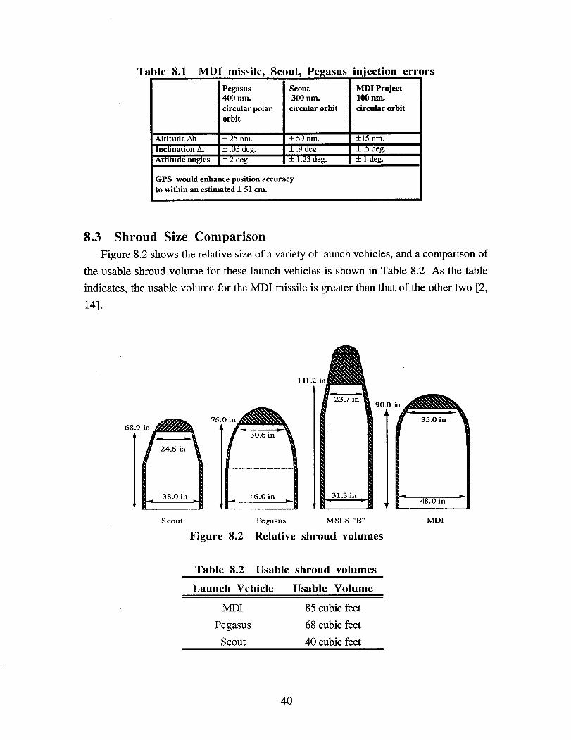
Table 8.1 MDI missile, Scout, Pegasus injection errors
Pegasus Scout MDI Project400 nm. 300 nm. 100 nm.
circular polar circular orbit circular orbitorbit
Altitude All + 25 nm. + 59 nm. +15 nm.
Inclination Ai + .03 deg. _+.9 deg. _+.5 deg.Attitude angles + 2 deg. + 1.23 deg. _ 1 deg.
GPS would enhance position accuracyto within an estimated + 51 cm.
8.3 Shroud Size Comparison
Figure 8.2 shows the relative size of a variety of launch vehicles, and a comparison of
the usable shroud volume for these launch vehicles is shown in Table 8.2 As the table
indicates, the usable volume for the MDI missile is greater than that of the other two [2,
14].
111
90
76.68 .9 in
1
Scout Pc gusus MSLS "B" MDI
Figure 8.2 Relative shroud volumes
Table 8.2 Usable shroud volumes
Launch Vehicle Usable Volume
MDI 85 cubic feet
Pegasus 68 cubic feet
Scout 40 cubic feet
40

8.4 Cost Comparison
The MDI design is a highly competitive launch system based on costs. MDI proposes
to charge 7.5 million dollars per launch. As mentioned before, the vendor will be required
to post 2/3 of the costs up front and the final 1/3 upon completion of the launch.
A comparison of the launch costs to the vendor for some comparable launch vehicles is
given in Table 8.3, and it clearly shows that the MDI design is the most cost effective
launch system [14].
Table 8.3 Launch cost comparison
Launch System Cost
MDI Minuteman II $7.5 million
Pegasus $12 million
Scout $15 million
41

9.0 MANAGEMENT STATUS
9.1 Management Goals
The primary management goal at Minotaur Designs Inc. was to efficiently use every
engineer's talent as best as possible. To achieve this purpose, The management team
implemented a dynamic program that promoted efficiency in the group by evenly
distributing the work among team members by individual talent and identifying/preventing
potential problems before they occurred. Therefore, by establishing a good communication
system within the team, the MDI management did not encounter any major problems and
was able to achieve the goals it set at the beginning of the project.
9.2 Program Organization
MDI's management team consisted of Rod McHaty as the team leader, Rodolfo
Gonzalez as the chief engineer/GNC subsystem manager, and Gordon MacKay as the
Structures subsystem manager. The team leader was MDI's primary point of contact, and
he kept.the contract monitor informed of the team's work progress on a regular basis, in
addition to any organizational changes or other potential problems that may have occurred.
The team leader set the project goals and milestones, in addition to adjusting manpower
within the team in order to conform to any major changes that were encountered over the
course of the project.
The chief engineer at the beginning of the project was Vu Pham. However, due to
other school obligations, Mr. Pham resigned his position halfway through the course of the
project and designated Rodolfo Gonzalez as his successor. Nevertheless, Mr. Pham stayed
involved in the management process as the project's chief administrative officer.
Overall, the chief engineer managed the technical aspects of the project and coordinated
the efforts of the team members in order to achieve the project goals. Consequently, the
chief engineer was the main point of contact for the team members, and all technical
developments within the project had to get his approval. Both the chief engineer and the
team leader served as assistant administrative officers by organizing the project records,
computing program costs, and maintaining the project's notebook.
42

The supporting organizational structure branched into two separate subsystem groups:
Structures and Guidance, Navigation and Control (GNC). The primary subsystem for the
project was the Structures subsystem and was managed by Gordon MacKay. The GNC
subsystem was managed by Rodolfo Gonzalez who later on became the chief engineer as
previously mentioned. The subsystem managers were responsible for dividing/distributing
the workload among the respective team members. Figure 9.1 shows the team's
organizational chart at the end of the project and the subsystem assignments. The
organization was flexible and was changed several times in order to meet new requirements
through out the course of the project.
9.3 Program Control and Schedule
Much of the work and designs in the two subsystems were interdependable. Therefore
certain subsystem work had to be completed before other work could begin. These
constraints made a PERT chart useful in the effective management of this project. The
PERT chart (see Figure 9.2) graphically organized the project's major milestones and
showed the tasks priority. Another important tool for management control was the GANT
chart (see Figure 9.3). These two tools provided a basis for a tight work schedule and
helped management foresee problems that would have occurred if a specific task was
delayed.
An agenda was prepared by the team leader or the chief engineer for every class
meeting. These agendas helped define the work that needed to be achieved and the
deadlines that needed to be met. Furthermore, the subsystem managers were required to
turn in a progress report memo to the team leader every week. These memos helped the
team leader track the progress in each of the two subsystems and also helped the rest of the
team members understand the progress made by their colleagues.
9.4 Workload Distribution
The management's primary concern at the beginning of this project was to insure an
even distribution of work among the team members. The subsystem managers were
responsible for distributing work assignments among the engineers. Workload and costs
43

were monitored through a Progress Planner document that needed to be tumed in by all
engineers every Monday. Engineers documented their work load on this Planner for
specific action items, and estimated other costs such as printing, copying, computer time,
and long distance phone calls.
9.5 Project Level of EffortI
Figure 9.0 summarizes the cumulative project effort through the end of the project. The
chart shows the actual team effort level compared to the effort predicted earlier in the
proposal. Due to increased man-hours in the management and engineering sections, MDrs
actual level of team effort surpassed the predicted levels. However, the increase in man-
hours led to better project results that made the MDI launch system more competitive than
the current available small satellite launch systems in the market.
1400
1200 Projected Effort .- .B
Actual Effort -'1000 ,"
..,
_n 800L_
0• = 600
4OO
2OO
pBO _
1 2 3 4 5 6 7 8 9 10 11 12
Week
Figure 9.0 Group level of effort
44

Minotaur Designs Inc.October November December January
Name Duration
Electrical Interf. Design 0d _10/15
MechanicalInterfacesStud. 10d 10/4 lijijijijijij_10/15i
MechanicalInterf.Design 0d i _10/15i!
InstrumentationStudies 10d 10/a. [Ijijljljij_ 10/15
InstrumentationDesign 0d _),10/15
PDR1 Oral Report 0d • 10125
PDR1 Documentation 6d 10/25 _ 11/1
PDR1 WrittenReport 0d ,I_11/1i
Second PreliminaryDesign 18d 11/1 _ v 11/24i
StructureIntegration 6d 11/1 i_i_i_ 11/8
GNC Integration 6d 11/1 iJijiji_J11/8
AlternativeStudies 3d ' 11/1 i_ 11/3
ProjectIntegration 3d 1/8 _ 11/10
PDR2 Oral Report 0d _,11/15
PDR2 Documentation 6d 11/17 jijl)i_IJ11/24
Final Report 0d @11!24
Crit ic al _11/////////////_ Ro l1e d Up <_
Noncritical DateProject: Minuteman II
Progress Start Date @Date: 11/24/93
Milestone • Completion Date
Summary ,v
Figure 9.3


Minotaur Designs Inc.Rod McHatyTeam Leader
Vu Pham I
Adnfinistrative Officer
Rodolfo Gonzalez i Budget AdministratorChief Engineer
1 I
Rodolfo Gonzalez _ ] Gordon MacKayGuidance & Navigational Control _ Structures
Propulsion _--_ Mechanical lnterfaces _
I BillAlexander i -- _ l _ 1
Instrumentation Greg Humble Rod McHaty/Vu PhamShroud Design _ Electrical Interfaces
Launch System Comparison Satelh" te Research_ Communications
Figure 9.1 Minotaur's Program Organization Structure

Minotaur Designs Inc.
I September J October 1131November I December I u..u.w I FetID Name Duration 291s 112119126,13 11011>124.I z11412112el51121191201219110123130161 1993 FALLSemester i 70d .i....... fllll'll'[[[,ll ...................... J.................. -_ 12/3 [ i
! i = = i i [
2 ProjectBegins i 0d _8/30 i i j i i3 ConceptualDesign i 15d i [ J J i '
...........................................................................................'......................' i l i ' i4 DesignConcepts j 15d i i j !i iJ
i i i '5 ConeptualDesignReview i 0d ! _,9/17 j ! i
• 6 ,..........................................................................................ProposalDevelopment i'......................12d 1 9/17 _ 10/4i ! i! [_ _Jl7 ..........................................................................................ProposalDelivered .;i.............2Od i il ', j i=
, , i
8 .........................................................................................[.............21d i 10/_ Tt.r _ 11/1 i ,i ,iFirstPreliminaryDesign i _ _ : i [ j
9 Structures Studies j 10d i 10/4 _ 10/15 [ '! i i'i E j !
10 ' ................................................................................................................Prelim.Struct.Design i 0d i i .10115 i ' J J.........................................................................................,......................i i i i11 SatelliteSelection/Analysis [ 5d J[ 10/41_i 1018 i! [J j [
......................................................................................... I. ......................
,_ _a,e,,,,oO.o,co i DO i .,o,_ i i i ,
_ .........................................................................................o..,,_,u_,es i'......................lO_ii lO,.__ ,o,,_,i ,i i ,i,4 .o,uo,es i '°°Z i ' i i..........................................................................................._,......................i _ i i15 GNC Design i 0d i i @10/15 i [ i J
..........................................................................................._......................i ! i ! !16 ElectricalInterfacesStud. i 10d i 10/4__ 10/15 _[ i i ii
Critical _ Rolled Up
Noncritical _ DateProject: Minuteman II
Progress Start Date @Date: 11/24/93
Milestone • Completion Date
Summary _,. .,
Figure 9.3

REFERENCES
1. Foster, Ronda. TRACOR Aerospace. Austin, TX. Interview in September 7, 1993.
2. Albert, Pat. MSLS Introductory guide. Martin Marietta. Denver, CO. Fax document
received October 6, 1993.
3. Hindman, George. Department of Aerospace Engineering, the university of Texas at
Austin. Interview in October 18, 1993.
4. Albert, Pat. Martin Marietta. Denver, CO. Fax document received October 15, 1993.
5. Albert, Pat Martin Marietta. Denver, CO. Fax documents received October 15 and
25, 1993.
6. Richards, Les. TRACOR Aerospace. Austin, TX. Interview in November 9, 1993.
7. Johnson, Steve. Jet Propulsion Laboratory. Telecommunications Division.
Pasadena, CA. Mailed document received October 10, 1993.
8. Thrusting Joint Separation Introductory Guide. TRACOR Aerospace. Austin, Tx.
9. Wertz James R., and Wiley J. Larson, ed. Space Mission Analysis and Design.
(Klewer Academic Publishers, Boston, 1991).
10. Ostroff, Ron. United States Air Force. Fax document received October 21, 1993.
11. Reentry Systems Launch Program. Boeing Aerospace Co. United States Air Force.
Washington, DC.
12. Comet User's Guide. United States Air Force. Washington, DC.
13. USRA/NASA. Spacecraft Subsystems. Department of Aerospace Engineering,
University of Texas at Austin. January 1993.
14. Isakowitz, Steven J., with the AIAA Space Transportation Systems Technical
Committee. International Guide to Space Launch Systems. (Washington, DC: AIAA
Publishing. 1991)
49

CONTACTS
MARTIN MARIETTA
• PatAlbert MSLS Project Engineer (303) 977-1049
• Mike Gughan MSLS Project Engineer (303) 977-9289
• David Steel MSLS Project Engineer (303) 971-6610
UNITED STATES AIR FORCE
• Captain Ron Ostroff USAF/NASA liaison (909) 382-2643
USRA
• Dr. Coleman USRA President (310) 825-1776
• Kevin Schmodel Washington DC office (202) 479-2609
• Jack Severe USRA/NASA (713) 244-2000
Jet Propulsion Laboratory (JPL)
• Rex Ridenoux Telecommunications Division (818) 354-2740
• Steve Johnson Telecommunications Division (818) 354-5808
TRACOR AEROSPACE
• Ronda Foster Engineer (512) 929-2407
• Les Richards Thrusting Joint Project Engineer (512) 929-4792
• David Short Engh_eer (512) 929-4043
Texas Space Grant Consortium
• Jim Wilson Engineer (512) 471-3583
50

APPENDIX A:PROSPECTIVE SATELLITE DATA
The following sections contain information on candidate satellites that could be
flown on a Minuteman II mission. The appendix contains information on missions,
dimensions, weight, power, attitude control, and communications for eight satellites. Most
of the satellite information in this appendix was provided to Minotaur Designs Inc. by JPL.
The following is a Table of Contents for this satellite appendix.
AIM .................................................. A2
BATSAT ............................................ A4
ACME 1............................................. A5
Eagle class lightsats ................................ A6
TOMS-EP ........................................... A7
HETE ................................................ A8
ALEXIS ............................................. A9
Microlab ............................................. A10
A-1

Asteroid Investigation with Microspacecraft (AIM)The AIM satellite was designed by the Jet Propulsion Lab (JPL) to perform flybys
of near earth asteroids for scientific investigation. The spacecraft must be placed in a 200
km parking orbit by the launch vehicle. The spacecraft then uses a STAR 17A injection
stage designed by Thiokol to reach the asteroids. Because the AIM satellite itself cannot be
easily spin stabilized, the injection stage will have thrust vector control to allow a non-
spinning injection. The AIM satellite has a hexagonal shape and is shown in Figure A1.
• Dimensions: - AIM - height = 23.6 in, width = 15.7 X 19.7 in.
STAR 17A - height = 30.7 in., diameter = 17.3 in.
- Total height = 54.3 in, Critical width = 19.7 in.
• Weight: - S/C wet = 56.6 lbs.
- SRM dry = 20.5 lbs.
- Propellant weight = 180.2 lbs.
- Total satellite weight = 258.4 lbs
• Power: - Maximum power generation at 1.2 AU is 55 W.
- Power generated by an array of multi-bandgap CulnSe 2
and GaAs solar cells.
• Attitude Control: 3-axis Attitude Control System with solid state inertial
measurement unit, star camera, course sun sensor, and
reaction wheel assembly with 3 small reaction wheels.
• Communication: Ka band
- Includes transponder, command detector unit, telemetry
modulation
unit, and an antenna.
A-2

O
Figure A1. AIM
A-3

BATSATThe BATSAT satellite was designed by Mockingbird Designs at the University of
Texas at Austin in the Spring of 1993. The mission of the BATSAT is to study X and Ka
band data transmission rates. BATSAT provides simultaneous X and Ka band
transmissions to three 34 meter high efficiency Deep Space Network (DSN) receivers.
BATSAT will be placed into a orbit of 1163 km and an inclination of 70 degrees. A
secondary goal of the satellite is to aid in training DSN personnel. Also, BATSAT has an
S-band transmitter which is used to study Doppler shift and blinking techniques. A
schematic of BATSAT is shown in figure A2.
• Dimensions: - height = 24.8 in.
- diameter = 24.8 in.
• Weight: - total launch weight = 144.2 lbs.
• Power: - maximum power consumption = 8.6 W
- power generated by Silicon solar cells.
• Attitude Control: - no data at this time.
• Communication: - Ka, X, or S band.
- downlink rates: Ka - 31.9 GHz.
X - 8.45 GHz.
S - 2.3 GHz.
- uplink rate = 7.19 GHz.
Figure A2. BATSAT
A-4

ACME 1ACME 1 was designed by JPL to use an ultraviolet spectrometer from an elliptical
lunar orbit to obtain science data on the Moon's atmosphere. ACME 1 requires a ballistic
insertion which means that there will not be a parking orbit around the earth. Therefore,
ACME 1 will need a STAR 27 injection stage designed by Thiokol in order to get to a lunar
orbit. In addition, the satellite will need to be spin stabilized at 60 rpm before separation
from the launch vehicle. The ACME 1 is shown in Figure A3.
• Dimensions: - ACME 1 - width = approx. 40 in.
- height = approx. 50 in.- STAR 27 - diameter = 27.3 in.
- Total height = approx. 76 in.
• Weight: - ACME 1 = 215 lbs.
- STAR 27 = 800 lbs
- Total weight = 1015 lbs.
• Power: - GaAs solar cells supply 70 W of power.
• Attitude Control: - 3-axis stabilized
- includes sun sensor, star tracker, and rate sensor.
• Communication: - S-band using two low gain antennas.
- data rate = 2000 bps.
Figure A3. ACME 1
A-5

Eagle Class LightsatsThe Eagle class lightsats developed by TRW and Defense Systems Inc. were
designed to carry out small, relatively inexpensive scientific investigations, technology
demonstrations, and operational missions. The payload and propulsion modules can be
custom tailored for each mission. The Eagle class lightsats module is shown in Figure A5.
• Dimensions: - Core vehicle: diameter = 38 in. (12-sided)
- height = 11.5 in.
- Payload module: - diameter = 38 in.
- height = 14.5 in.
- Propulsion module: - diameter = 38 in.
- height = 23 in.
- Power module: - diameter = 38 in.
- height = 11.5 in.
- Total possible height = 60.5 in.
- Critical diameter = 38 in.
• Weight: - No data at this time.
• Power: - Solar ceils on fixed or articulated arrays.
- orbital avg. power up to 450 W.
- 30 W power from core vehicle.
• Attitude Control: - 3-axis spin or gravity gradient stabilization.
• Communication: - S-band and UHF-RF options.
- downlink = 1.0 Mbps maximum.
- uplink = 2.4 kbps maximum.
(_Payload Module.
CoreVehicleModule=
PropulsionModule _
Figure A5. Eagle class lightsats modules
A-6

Total Ozone Mapping Spectrometer Earth Probe(TOMS-EP)
The TOMS-EP was designed by TRW for the NASA Goddard Space Center. The
satellite mission is to perform daily mapping of the global distribution of Earth's ozone
layer. TOMS-EP will be separated from the launch vehicle at an altitude of 355 km and
then proceed to a sun synchronous 955 km high polar orbit. The bus is a variation of the
Eagle class lightsats. TOMS-EP is shown in Figure A6.
• Dimensions: - diameter = 44 in.
- height = 70 in.
• Weight: - payload = 77 - 132 lbs.
- propellant = 155 lbs. full tank.
• Power: - 25 W avg. power demand.
• Attitude Control: - 3-axis stabilized.
• Communication: - S-band
- downlink > 0.25 Mbps.
- uplink = up to 2 kbps.
6Thrusters,10.4to1.0Ibeach)
SolarArray
Deployed_ All-
Zenith RIl-&-drainOmni
Antenna MonopropellantBlow-down
Orbit Tank(160Ib)Adjust
Module Batter mics
EquipmentModule--
Fine Solar
StowedPayload-to-spacecraftUmbilical
TOMS NadirInstrument toni
Figure A6. TOMS-EP
A-7

High Energy Transient Experiment (HETE)HETE was designed by AeroAstro for MIT in order to detect and observe high
energy events in the gamma ray, X-ray, and UV spectra. The HETE is placed in a 550 km
circular orbit with an inclination less than 40 degrees. HETE is shown in Figure A7.
•Dimensions: - diameter = 26 in.
- height = 35 in.
•Weight: - 265 lbs. maximum.
•Power: - 30 W avg. supplied to payload.
•Attitude Control: - sun pointing.
•Communication: - S-band.
- downlink = 230 kbps.
- uplink = 7.5 kbps.
Figure A7. HETE
A-8

ALEXISALEXIS was designed by AeroAstro for the Los Alamos National Laboratory to
provide high resolution maps of low energy X-ray sources and ionosphere physics.
ALEXIS is placed in a 750 km circular orbit at an inclination of 65 degrees. ALEXIS is
shown in Figure A8.
• Dimensions: - diameter = 23.6 in.
- height = 39.4 in.
• Weight: - 254 lbs.
• Power: - supplies an avg. of 50 W to the payload.
• Attitude Control: - sun pointing with a 2 rpm spin.
• Communication: - S-band
- downlink = 750 kbps.
- uplink = 9.6 kbps.
Figure A8. ALEXIS
A-9

MicrolabMicrolab was designed by Orbital Sciences Corporation in order to support small
space based science missions. Some of the applications that Microlab can accommodate are
remote sensing, communications, space physics, and materials research. The customer
provided payloads will be integrated into the spacecraft bus. The Microlab bus is shown in
Figure A9.
• Dimensions: - diameter = 38 in.
- height = 12 in.
• Weight: - experiment = 100 lbs. maximum.- S/C bus - no data at this time.
• Power: - Two deployable solar arrays
- 100 W provided to payload.
• Attitude Control: - Nadir pointing or sun pointing.
- spin stabilized.
- optional 3-axis stabilization.
• Communication: - S-band.- Payload data rate = 2.0 Mbps peak.
_ 38" Dial_lea I
• ,. I
Fxnclimpn! Volume BO$ AviOniCS
Figure A9. The Microlab Bus
A-10

APPENDIX B:Launch Performance Analysis
In order to compute the attainable orbits for different rocket configurations, MDI set up
a TK! Solver Model with simple rocket equations, (see appended TK! SOLVER rule and
variable sheet). All stage specific impulses, propellant masses and dry masses are from the
MSLS documentation [2]. The launch site latitudes for Vandenberg and Cape Canaveral
were found in Wertz[Wertz:]. The wafer and support structure masses were based those
used for the MSLS. The shroud mass was computed by MDI. The velocity losses during
launch were estimated by matching up the TK! SOLVER calculated altitude with the
previous MSLS, configuration B analysis, see Figure B. 1.
1200
1000
D
800
60O
_ 400
200
_ I I I I I I I a I I I I I I i i I I I I I I Im i i m i
0 100 200 300 400 500 600
Orbit Altitude (rim)
Figure B.1 MSLS configuration B performance.
The simplified model uses the basic rocket equation,
Av= g. Isp. ln(m°///mf /
where g is the gravity constant at the surface of the Earth, m0 is the mass before the
burn, mf is the mass after the burn, Isp is the specific impulse, and Av is the total velocity
change. Notice in the rule sheet that the various stages are accounted for.
B-1

The equations take into account the initial boost due to the rotation of the Earth, and
assume'that the complicated launch profile can be modeled as two impulsive bums (dv
launch and dvins) as indicated in the rules sheet and Figure B.2.
h _ orbit
V
Figure B.2 TK! model equation diagrams
Although the equations are an extreme simplification of the true trajectory (which must
be integrated), the model was considered valid for the following reasons. By appropriately
calibrating the velocity losses, the MDI derived performance chart very nearly duplicated
the MSLS chart, which was derived with a sophisticated integrating program [2]. Also,
when a STAR 17A injection stage was added to the model, the improved performance was
on the order of the performance for the Pegasus with a STAR 17A. Since the MDI shroud
is as wide as the MSLS third stage (but notice it isn't as thick as the MSLS "B" shroud),
MDI expects similar drag characteristics as the MSLS, configuration "B" missile.
The TK! model was used to generate the expected launch performances indicated in
Figures B.3 and B.4. Notice that when a STAR 27 is used, the permissible payload mass
is limited to 706 lbm due to a mass-above-the-bulkhead constraint of 1500 lbm, and the
injection stage weighs 794 lbm.
B-2

1200
00 500 1000 1500 21300 2500
orbit altitude [nm]
Figure B.3 Launch Performance for Launches from Vandenberg
1000-
_, 800.600-
•"_ 400-
oiiNi_iiiiiiiiii_':iiiiiiiii ___0 500 1000 1500 2000 2500
orbit altitude [nm]
Figure B.4 Launch Performance for Launches from Cape Canaveral
B-3

Sample TK! Solver Variable Sheet
St InPut Name OutPut Unit Comment
6378.137 re km radius of the Earth
7.2921E-5 we rad/s rotation rate of Earth
.90981 g km/s2 gravity const, at Earth surface
398600.44 mu km3/s2 gravity parameter
272 mwaf kg combined mass of wafers
109 mshr kg mass of shroud
20786 mIp kg stage I prop. mass
2129 mid kg stage I dry mass
6237 mIIp kg stage II prop. mass
797 mIId kg stage II dry mass
3313 mIIIp kg stage III prop. mass
338 mIIId kg stage III dry mass
0 mISp kg injection stage prop. mass
1 pmf prop. mass fraction
mISd 0 kg injection stage dry mass
268 Ispl s specific impulse 1
287 Isp2 s specific impulse 2
285 Isp3 s specific impulse 3
287.8 Isp4 specific impulse I.S.
0 dvster km/s steering loss
" 0 dvdrag km/s drag loss
0 dvgrav km/s gravity loss
1.2708961 dvatpr km/s atm. press, loss
h 277.8 km circular orbit altitude
rp 6378.137 km perigee radius of x-fer orbit (re)
ra 6655.937 km apogee radius of x-fer orbit (ins)
a 6517.037 km semi-major axis of transfer orbit
rvb 5257.6505 km radius of Vandenberg
vvb .38339437 km/s velocity of Vandenberg
vp 7.9891665 km/s peri.vel, of x-fer orbit
va 7.6557213 km/s apo.vel, of x-fer orbit
vins 7.7386336 km/s insertion vel. for cir. orbit
dvlaunc 8.1099709 km/s first speed dv.
dvins .08291233 km/s second speed dv.
34.48 lat deg latitude of Vandenberg
L 104 i deg orbit inclination
betal -17.06637 deg inertial launch azimuth candidate
beta2 197.06637 deg inertial launch azimuth candidate
eta 107.06637 deg local angle b/w vvb and vp
azl 199.6566 deg local launch azimuth (i>87)
az2 160.3434 deg local launch azimuth (i<87)
m0 34144.978 kg mass before burn 1
ml 13358.978 kg mass after burn 1
m2 11229.978 kg mass before burn 2
m3 4883.9778 kg mass after burn 2
m4 4086.9778 kg mass before burn 3
m5 773.97783 kg mass after burn 3
m6 163.97783 kg mass before burn 4
m7 163.97783 kg mass after burn 4
mf 163.97783 kg mass at orbit ins. (mpay)
dvl 2.4671993 km/s first burn
dv2 2.3442357 km/s second burn
dv3 4.6523443 km/s third burn
dv4 0 km/s fourth burn
dvtot 9.4637793 km/s total burn
mpay 163.97783 kg mass of the payload
B-4

TK! Rule Sheet
rp = re
ra = re + h
rvb = re * cosd(lat)
vvb = we * rvb
m0 = mIp + mid + mIIp + mshr +mIId + mIIIp + mIIId + mISp + mISd + mpay + mwaf
ml = m0 - mIp
m2 = ml - mid
m3 = m2 - mIIp - mshr
m4 = m3 -mIId
m5 = m4 - mIIIp
m6 = m5 - mIIId - mwaf
m7 = m6 - mISp
mf = m7 - mISd
pmf _ mISp/(mISp + mISd)
dvl = g * Ispl * in(m0/ml)
dv2 = g * Isp2 * in(m2/m3)
dv3 = g * Isp3 * in(m4/m5)
dv4 = g * Isp4 * in(m6/m7)
dvtot = dvl + dv2 + dv3 + dv4
a = (ra + rp)/2
vp = sqrt(mu * (2/rp - l/a))
va = sqrt(mu * (2/ra - l/a))
vins = sqrt(mu/ra)
dvins = vins - va
sind(betal) = cosd(i)/cosd(lat)
beta2 = 180 - betal
eta = beta2 - 90
dvlaunch = sqrt(vvb^2 + vp^2 - 2*vvb*vp*cosd(eta)
sind(eta)/dvlaunch = sind(alphal)/vp
alpha2 = 180 - alphal
azl = 270 - alphal
az2 _ 270 - alpha2
dvlaunch + dvins + dvdrag + dvgrav + dvster + dvatpr = dvtot
hnm = h / 1.852
mlbs = mpay * 2.24
B-5

APPENDIX C:Finite Element Model Specifications
Finite element properties are listed in this appendix. MDI felt that time would be best
spent coding a finite element model in the same language as the existing Minuteman finite
element model. To this end this appendix lists all the parameters needed to create the finalfinite element model.
C.1 Payload Support Bulkhead
The payload support bulkhead is identical to the MSLS payload support bulkhead with
the exception of the holes drilled in the bulkhead. The MDI design relies on a quadrilateral
truss design. MDI's design requires the MSLS bulkhead be delivered without payload
attach holes. The electrical interface is also different between designs. MSLS has three
electrical connector groups. MDI will have only one. The PSB then has the same
elemental and dimensional properties as the MSLS. The PSB dimensions are listed in
Table C. 1.1. Material properties are listed in Table C. 1.2. The PSB is shown in Figure
C.I.1.
Table C.I.1 PSB dimensions
Height 15 inches
Base Diameter 52 inches
Bulkhead Diameter 47.5 inches
Truss attach hole radius 20 inches
Electrical hole radius 20 inches
Electrical hole off axis 45 de_rees
Table C.1.2 PSB material properties
Material Aluminum 7075
Finish Alodine 600
Thickness 2.0 inches
Weight 25 lb.
Truss tension pullout capability 15,000 lb. per truss
C-1

ElectricalConnector
TopView
;tar 17A
Star 27
Side
Figure C.1.1 Payload Support Bulkhead
C.2 Truss Elements
The truss elements are composed of three members. There is a top piece which attaches
to the lip of the payload vehicle. There is a variable length center section that has a nominal
length of 32 inches. There is also a bottom piece which connects to the PSB. The truss is
shown in Figure C.2.1. The material properties of the truss support structure is shown in
Table C.2.1. Detailed modeling of the truss structure will be concluded during the R&D
phase of the project.
C-2
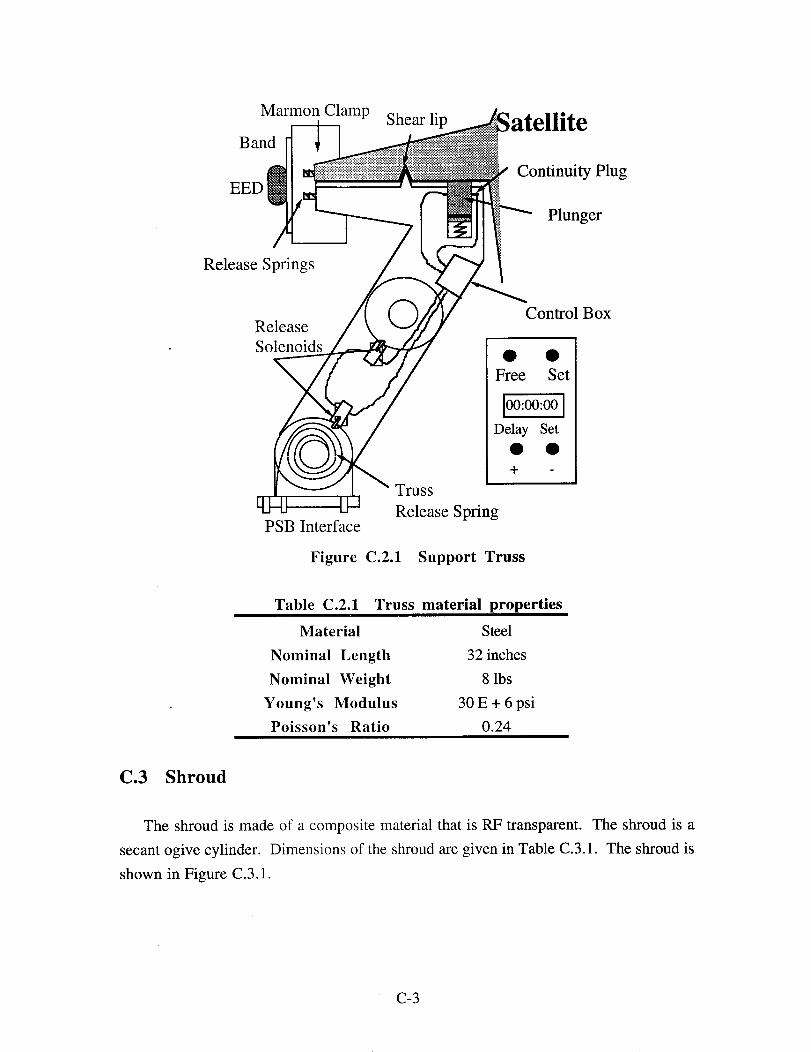
Marmon Clamp Shear lipBand
Continuity PlugEED
Plunger
Release Springs
Control BoxRelease
Solenoids • •Free Set
100:00:00]Delay Set
+
Truss
Release SpringPSB Interface
Figure C.2.1 Support Truss
Table C.2.1 Truss material properties
Material Steel
Nominal Length 32 inches
Nominal Weight 8 lbs
Young's Modulus 30 E + 6 psi
Poisson's Ratio 0.24
C.3 Shroud
The shroud is made of a composite material that is RF transparent. The shroud is a
secant ogive cylinder. Dimensions of the shroud are given in Table C.3.1. The shroud is
shown in Figure C.3.1.
C-3

Table C.3.1 Shroud dimensions
Diameter 52 inches
Height 120 inches
Weight 214 lbs
VSS
HSS
Figure C.3.1 MDI shroud
C-4

APPENDIX D:Payload User's Guide
For the benefit of satellite customers who are considering using the MDI missile as their
launch vehicle, MDI has compiled all the satellite concerns in one area. The main points
discussed are the attainable orbits of launch system, the mechanical interfaces used to
mount the satellite to the missile, electrical interfaces available for the payload, and launch
system costs.
D.1 Attainable Orbits
Figures D. 1 and D.2 summarize the attainable orbits customers can expect from the
MDI launch system. To meet a wide range of orbit needs, MDI can provide orbit
inclinations between 29° and 57 ° by launching from Cape Canaveral and inclinations
between 57° and 104° by launching from Vandenberg. The customer may use either a
STAR 17A or STAR 27 injection stage if the orbit requirements demand better
performance.
r-_ 1000-800-
!_ 600- _O I. !_iiiiii_:_............
400 ='N°I ....... ::'_:._::_i_i_i_!__:::..
-200_ _ -_;i%""":""""'_'_':i_iiiiii"i"i"i"iiiiiiiiiiiiiii_iif! '_
_ _
0 500 1000 1500 2000 2500
orbit altitude [nm]
Figure D.1 Launch Performance at VAFB Launch Site
D-1

.1000.__._ 800.r_
600-
-_ 400.¢¢
0;_ 200-¢h
00 500 1000 1500 2000 2500
orbit altitude [nm]
Figure D.2. Launch Performance at Cape Canaveral Launch Site
Like all launch systems, some orbit insertion error that the payload will need to tolerate.
MDI expects orbit altitude errors of + 15 nm and inclination errors of + 0.5 °.
D.2 Mechanical Interfaces
Payload customers may connect directly to the missile bulkhead with use of the flexible
MDI marmon clamp, see Figure D.3. If the payload requires an injection stage, MDI will
provide for an interface between the injection stage and payload as seen in Figure D.4.
Marmon
Clamp
Figure D.3. MDI Marmon Clamp
D-2

Marmon Clamp Shear ;atelliteBand
Continuity PlugEED
Plunger
Release Springs
Control BoxRelease
Solenoids • •Free Set
ioo:oo:ooIDelay Set
+
Truss
Release SpringPSB Interface
Figure D.4. MDI Payload Attach Fitting
D.3 Launch Time and Costs
Once a customer decides to use the MDI missile as their launch system, they can expect
a launch after 6 months and the following launch costs:
Launch Type Cost
Regular Launch $ 7,500,000
Added STAR 17A +$500,000
Added STAR 27A +$1,000,000
D-3

D.4 Expected Launch Environment
Figures D.4 thru D.9 show the anticipated launch environment that a potential satellite
will be exposed to.
160
14080
120
,o 100
_ _ _ .,,
[6° I
40
20
0 n ''' :' zn n II II' In nn aln n'': .... l
0 20 40 60 80 100 120
Time (see)
Figure D.5 Thermal environment
16
14
_'1_. " Ambiant12
"_ 10 %,_ PressureN_ -- -- 13--- - Internal8 Mhm
-'%= Pressure
6 _,__" 4
2 "_- El-..r'L _0 ..... , .... 1 ' ' _ -_- = -'-'_ -'_-53
0 20 40 60 80
Time (see)
Figure D.6 Pressure environment
D-4

0.1 Titan IUS q_k
0.075
0.05
0.025
0
1 10 100 1000 10000
Frequency (Hz)
Figure D.7 Random vibration environment
1000
"_ 100
o0
o 10.<
l ! I I ! IIII i I I I I I'''' i , a , , ,l,,, i
10 100 1000 10000
Frequency (Hz)
Figure D.8 Shock environment
D-5


