
FeatureIT: A Platform for Collaborative Software Development
by
GAVIN GEORGE SILLER
(3027-134-7)
Submitted in accordance with the requirements for the degree of
MASTER OF SCIENCE
in the subject
INFORMATION SYSTEMS
at the
UNIVERSITY OF SOUTH AFRICA
SUPERVISORS: HELENE GELDERBLOM AND PAULA KOTZE
FEBRUARY 2013

2
I declare that “FeatureIT: A Platform for Collaborative Software Development” is my own work and that all the sources that I have used or quoted have been indicated and acknowledged by means of complete references.
______________________________ ________________________________
SIGNATURE DATE

3
ABSTRACT
The development of enterprise software is a complex activity that requires a diverse set of
stakeholders to communicate and coordinate in order to achieve a successful outcome. In this
dissertation I introduce a high-level physical architecture for a platform titled FeatureIT that has
the goal of supporting the collaboration between stakeholders throughout the entire Software
Development Life Cycle (SDLC). FeatureIT is the result of unifying the theoretical foundations
of the multi-disciplinary field of Computer Supported Cooperative Work (CSCW) with the
paradigm and associated technologies of Web 2.0. The architecture was borne out a study of
literature in the fields of CSCW, Web 2.0 and software engineering, which facilitated the
identification of functional and non-functional requirements necessary for the platform. The
design science research methodology was employed to construct this architecture iteratively to
satisfy the requirements while validating its efficacy against a comprehensive set of scenarios
that typically occur in the SDLC.

4
Table of Contents
Chapter 1: Introduction ................................................................................................................... 9
1.1 Background ...................................................................................................................... 9
1.2 Research problem ........................................................................................................... 10
1.3 Research aims ...................................................................................................................... 11
1.4 Research methodology ........................................................................................................ 11
1.5 Assumptions, delimitations and limitations ........................................................................ 13
1.6 Significance of the study ..................................................................................................... 14
1.7 Layout of the dissertation .................................................................................................... 14
Chapter 2: Literature review ......................................................................................................... 16
2.1 Introduction ......................................................................................................................... 16
2.2 Collaboration within the enterprise context ........................................................................ 16
2.3 Collaboration and the software development process .................................................... 20
2.3.1 Introduction .................................................................................................................. 20
2.3.2 Stakeholders in the software development process ...................................................... 21
2.3.3 The Software Development Life Cycle (SDLC) .......................................................... 24
2.3.4 Information requirements for software development ................................................... 26
2.3.5 Distributed software development ................................................................................ 27
2.3.6 Conclusion .................................................................................................................... 29
2.4 Collaboration using Computer Supported Cooperative Work (CSCW) and Groupware ... 29
2.4.1 Introduction .................................................................................................................. 29
2.4.2 The technical nature of CSCW systems ....................................................................... 30
2.4.3 The social nature of CSCW systems ............................................................................ 33
2.4.4 The application of CSCW in software development: Computer Assisted Software Engineering (CASE) tools ..................................................................................................... 34
2.4.5 Problems with CSCW systems adoption ...................................................................... 35
2.5 Web 2.0 and its impact on collaboration ............................................................................. 37
2.5.1 What is Web 2.0?.......................................................................................................... 37

5
2.5.1.1 The Web 2.0 paradigm .............................................................................................. 37
2.5.1.2 Web 2.0 technology enablers..................................................................................... 39
2.5.1.3 Aggregating Web 2.0 applications: web portals ........................................................ 45
2.5.2 Conclusion ........................................................................................................................ 46
2.6 A critique of Web 2.0 .......................................................................................................... 47
2.7 What is Enterprise 2.0? ....................................................................................................... 48
2.8 Web 2.0 collaboration applications versus Computer Supported Cooperative Work Systems – substitute or complementary? .................................................................................. 50
2. 9 Functional requirements for constructing a modern collaboration system ........................ 52
2.10 Technology requirements for constructing a modern collaboration system ..................... 54
2.11 Implementing a collaboration platform for the enterprise ................................................ 55
2.11.1 Cloud computing layers and services ......................................................................... 56
2.11.2 Cloud computing deployment models ........................................................................ 58
2.12 Limitations of current collaboration solutions in the software development process ....... 59
2.13 Summary and conclusion .................................................................................................. 61
Chapter 3: Research design and methodology .............................................................................. 63
3.1 Introduction .................................................................................................................... 63
3.2 Research philosophy ...................................................................................................... 63
3.2.1 Research philosophy background ................................................................................. 63
3.2.2 Research philosophy applicable to my study ............................................................... 66
3.3 Research strategy and design ......................................................................................... 68
3.3.1 Research strategy and design background .................................................................... 68
3.3.2 Research strategy applicable to this study .................................................................... 70
3.4 Research method ............................................................................................................ 72
3.4.1Research method background ........................................................................................ 72
3.4.2 Research method applicable to this study ............................................................... 75
3.4.2.1 Awareness of a problem ............................................................................................ 75
3.4.2.2 Suggestion of a solution ............................................................................................ 76
3.4.2.3 Development of the artefact ...................................................................................... 77

6
3.4.2.4 Evaluation of the artefact ........................................................................................ 78
3.4.2.5 Conclusion ................................................................................................................. 78
3.5 Conclusion ...................................................................................................................... 79
Chapter 4: Research results ........................................................................................................... 80
4.1 Introduction .................................................................................................................... 80
4.2 The problem domain ........................................................................................................... 81
4.3 The requirements for a collaboration platform to facilitate the process of software development in the enterprise ................................................................................................... 84
4.3.1 Functional requirements for the collaboration platform .................................................. 84
4.3.1.1 Ease of entering software system requirements into the collaboration platform ...... 84
4.3.1.2 Information inside the platform must be viewable, modifiable and extendable for authorized users ..................................................................................................................... 85
4.3.1.3 The view of the system state must be determined by user role ................................. 86
4.3.1.4 The information in the platform must be searchable ................................................. 87
4.3.1.5 The collaboration platform must support the entire SDLC and all stakeholders ...... 87
4.3.1.6 Users must be aware of the activities taking place within the collaboration platform ............................................................................................................................................... 87
4.3.1.7 The collaboration style that best suits the user must be supported by the platform .. 88
4.3.2 Non-functional requirements for the collaboration platform ........................................... 88
4.3.2.1 The collaboration platform must be extensible ......................................................... 88
4.3.2.2 The collaboration platform must have open application programming interfaces (API’s) ................................................................................................................................... 89
4.3.2.3 The collaboration platform must co-exist and utilize with existing enterprise infrastructure .......................................................................................................................... 89
4.3.2.4 The collaboration platform must have multiple deployment options ........................ 90
4.4 Introducing FeatureIT ......................................................................................................... 90
4.4.1 The FeatureIT collaboration platform for software development ................................ 91
4.4.2 How FeatureIT facilitates collaboration throughout the SDLC ................................... 93
4.4.2.1 FeatureIT’s role during the development of a new software system ......................... 93
7
4.4.2.2 FeatureIT’s role during a project enhancement ......................................................... 97
4.4.2.3 FeatureIT’s role during operational project maintenance.......................................... 97
4.5 Integration of FeatureIT into the enterprise ........................................................................ 98
4.6 Extensibility and customization of the FeatureIT platform ................................................ 99
4.7 High-level architecture of the FeatureIT platform ....................................................... 101
4.7.1 Feature input/progress notification and workflow components ................................. 104
4.7.2 Platform logic, data domain and search components ................................................. 104
4.7.3 Enterprise infrastructure integration layer .................................................................. 106
4.7.4 Applications deployed inside the FeatureIT collaboration platform .......................... 107
4.7.5 Presentation subsystem (implemented using a web portal) ........................................ 107
4.7.6 External application integration layer......................................................................... 108
4.7.7 FeatureIT’s social container utilization ...................................................................... 109
4.8 Summary of the FeatureIT components ............................................................................ 110
4.9 Conclusion ......................................................................................................................... 113
Chapter 5: Validating the high-level architecture ....................................................................... 114
5.1 Introduction .................................................................................................................. 114
5.2 Scenarios validating the FeatureIT architecture ........................................................... 114
5.2.1 Impetus (the fictitious organization)........................................................................... 115
5.2.2 The current operating model of the Sales IT division ................................................ 115
5.2.3 Scenarios that illustrate how FeatureIT is introduced into the enterprise from an infrastructure perspective .................................................................................................... 117
5.2.3.1 Integration with the existing user registry ............................................................... 118
5.2.3.2 Integration with the existing source control management system ........................... 118
5.2.3.3 Integration with the existing document stores ......................................................... 118
5.2.3.4 Deployment and operation of FeatureIT ................................................................. 119
5.2.4 Scenarios that illustrate the use of FeatureIT at Impetus during the SDLC ............... 119
5.2.4.1 Requirement for a new project entered into FeatureIT............................................ 123
5.2.4.2 Analysis begins on the feature request .................................................................... 123
8
5.2.4.3 Deciding on whether the feature is worthy of realization ....................................... 124
5.2.4.4 Intensive business analysis to realize the feature begins ......................................... 125
5.2.4.5 Systems analysis to realize the feature begins ......................................................... 126
5.2.4.6 Systems architecture of the new system is defined and documented ...................... 127
5.2.4.7 The new commission system is designed ................................................................ 127
5.2.4.8 Development of the new commission system commences ..................................... 128
5.2.4.9 Testing the development efforts of the commission system ................................... 129
5.2.4.10 Implementing the production infrastructure for the new commission system ...... 129
5.2.4.11 Repairing a defect on the commission system ...................................................... 130
5.2.4.12 Making an operational change to the commission system .................................... 130
5.2.4.13 Implementing an enhancement to the commission system ................................... 130
5.2.5 Scenarios that illustrate the extensible nature of FeatureIT ....................................... 131
5.2.5.1 End user extensibility of FeatureIT ......................................................................... 131
5.2.5.2 Software developer extensibility of FeatureIT ........................................................ 132
5.3 Conclusion .................................................................................................................... 132
Chapter 6: Research study conclusion ........................................................................................ 134
6.1 Summary ........................................................................................................................... 134
6.2 Contribution ...................................................................................................................... 135
6.3 Reflections on the study .................................................................................................... 137
6.4 Future directions ................................................................................................................ 138
6.5 Conclusion ......................................................................................................................... 138
References ................................................................................................................................... 140

9
Chapter 1: Introduction
1.1 Background
Collaboration utilizing technology has become a prominent theme in our daily lives and
correspondingly features in the academic and information systems trade literature. Web 2.0 is the
term used to describe the concepts and technologies that are enabling collaboration on a scale
never before possible (O'Reilly, 2005). Philosophies such as user-generated content, utilizing the
crowd to solve problems and add value to information, and the internet as a software application
platform are coupled with technologies such as AJAX and Rich Internet Applications (RIA’s) to
produce applications that promote collaboration. Examples of these types of applications are
wikis, blogs and mashups.
Not long after Web 2.0 emerged organizations realized that they could utilize this collaboration
technology inside their institutions to reduce costs, increase information sharing and produce
better quality deliverables (Coleman & Levine, 2008). This trend was termed Enterprise 2.0
(McAfee, 2006) and it is now commonplace for Web 2.0 applications to be found in the work
environment.
A precursor to the Web 2.0 and Enterprise 2.0 concepts, that had similar goals in terms of
collaboration, is Computer Supported Cooperative Work (CSCW). CSCW is the discipline
concerned with the way in which computers and networks support communication and group
work (Lyytinen & Ngwenyama, 1992). Groupware, the physical system manifestation of the
CSCW paradigm, never gained widespread popularity due to a number of technical and design
issues such as hardware and operating system incompatibilities and the inability to understand
the effects of how groups and organizations function (Grudin, 1988).
One critical activity that takes place in many enterprises, across diverse industries, is the
development of software systems. The development of enterprise software is notorious for
delivering systems which are over budget, exceed time lines, are of poor quality and do not meet
the users’ expectations (Eeles & Cripps, 2010). I define an enterprise as an organization that is of
no particular size but whose software systems are critical for the successful operation of the
institution.

10
In this dissertation I marry the discipline of CSCW with the paradigm and associated
technologies of Web 2.0 to deliver a collaboration architecture that aids in the construction of
quality enterprise software. The development of enterprise software requires that many
individuals, with diverse roles and concerns, work together to produce a system that meets both
its functional and non-functional requirements. Considering that technology has become an
enabler to collaboration efforts, it is ironic that there exist no platforms that span the entire
Software Development Life Cycle (SDLC) process and all its participants.
The results of my study culminated in a high-level architecture for a collaboration platform that
enables the effective communication and coordination among all stakeholders in the
development of enterprise software.
1.2 Research problem
In my role as an architect involved in the creation of enterprise software, I am acutely aware of
the complexities inherent in this process. One of the primary reasons for this complexity is the
number of diverse stakeholders and their requirements throughout the SDLC. These stakeholders
need to collaborate in order to produce a system of value. The Web 2.0 paradigm of participation
and open, standards-compliant platforms appeared to have the potential to facilitate and enhance
the collaboration process. A survey of the existing system landscape and a study of the literature
confirmed that no such platforms have been devised. Products do exist that assist in collaboration
for certain of the phases of the SDLC (such as requirements gathering or software defect
management) but no single product supports collaboration across the entire SDLC. It was also
evident that an open platform that enables the building, assembling and configuring of
collaboration components to support the coordination and communication activities that occur
during the software development process does not exist.
As a result of this survey I undertook a research effort to formulate the architecture for a
platform that would assist in the collaboration required during the creation of enterprise software.
The platform presented in this study is also able to adapt to the structural dynamics of the
organization in which it is deployed, and the inevitable changes that will occur to the
organization over time.

11
1.3 Research aims
The purpose of this study was to define an architecture necessary for the construction of a
collaboration platform that would assist in the production of quality enterprise software. This
architecture was borne out of a comprehensive list of functional and non-functional requirements
necessary to support the complete SDLC.
The research questions investigated were therefore:
1. What are the functional and non-functional requirements for an architecture to support the
collaboration requirements throughout the complete SDLC?
2. What should an architecture for the construction of a collaboration platform to assist the
production of enterprise software (and that fulfil the requirements identified in 1 above) look
like?
The proposed platform embraces the paradigms and technologies of the Web 2.0 and Enterprise
2.0, yet is based on the firm theoretical principles of CSCW.
The architecture defined in this dissertation is the basis for the implementation of the proposed
platform.
1.4 Research methodology
Henver et al. (2004) states that there are two paradigms that comprise research in the field of
information systems:
1) The behavioural science paradigm that attempts to understand and then predict future
behaviour of the parties of interest.
2) The design science research paradigm the intention of which is to create deliverables that
enhance the current abilities of humans.
I employed design research as the paradigm for conducting my study. This is because my study
resulted in the architecture (deliverable) of a collaboration platform supporting the development
of enterprise software.

12
My suggestion for a solution involved a thorough study of the literature in the fields of:
1) Software engineering, to understand the requirements across the SDLC for effective
collaboration in the construction of enterprise software.
2) CSCW, to utilize the interdisciplinary knowledge in this field to understand how groups of
individuals work together and how systems should be designed to support effective
collaboration.
3) Web 2.0 and Enterprise 2.0, to understand the new technologies that underlie the modern
Web 2.0 philosophies of collaboration on a mass scale.
The development of my architecture resulted from the knowledge I gained through a literature
review that was conducted to provide me with functional and non-functional requirements
necessary for constructing an architecture for a collaboration platform to support the creation of
enterprise software.
This architecture produced was evaluated against how well it supported the functional and non-
functional requirements of a collaboration system that were identified during my literature study.
This evaluation was performed by validating the architecture against scenarios, typical in the
SDLC, that I formulated, which concretized these requirements.
Several times during the study, while validating the candidate architecture, I realized that it failed
to meet the requirements of a collaboration platform to support the development of enterprise
software. This resulted in me revisiting the literature to better understand how to construct a
more effective architecture (or to better understand whether the requirements themselves were
misunderstood or even unnecessary).
My research effort resulted in an architecture for a platform that supports the development of
quality enterprise software that was validated against a comprehensive set of real life scenarios
that take place during the SDLC.

13
1.5 Assumptions, delimitations and limitations
The proposed architecture was documented using only part of the “4+1” view model for systems
architecture (Kruchten, 1995). The “4+1” view model documents a software architecture using
the following distinct but complementary views:
1) The logical view that illustrates the system functionality to primarily non-technical end users.
2) The development view that shows the system in such a way that designers and programmers
can begin designing and building the system.
3) The process view that illustrates the dynamic nature of the system and how the various
subcomponents communicate at run-time.
4) The physical view which shows the physical topology of the system’s components,
particularly where these subcomponents will be deployed and how they will communicate
with each other.
These four views of a system are complemented by selected use cases or scenarios that assist in
clarifying the architecture of the system as a whole. This is the “+1” portion of the
documentation method’s name.
I employed only the physical view to document the FeatureIT collaboration platform. I did this
because I believe it offers the best high-level view of the system components and the manner in
which they interact.
This view uses the “box and lines” diagrams (Rozanski & Woods, 2012, p. 222) to represent the
visual aspects of the architecture documentation. Chapter 5 supplements this logical view with
scenarios to ensure traceability between the functional requirements and the proposed
architecture. This architecture documentation approach can be considered sufficient for
presenting a proposed system solution to stakeholders (Reekie & McAdam, 2006).
The proposed platform has not been implemented as an executing system. To successfully
implement the platform, I believe the remaining three views should be documented.

14
Finally, I have purposefully neglected to map the components of the FeatureIT platform to
specific products that can aid in implementation. I believe that mapping the architecture to
precise platforms and products should be done as close to implementation time as possible in
order to concentrate on the “what” of the problem as opposed to the “how”.
1.6 Significance of the study
I do not suggest that a collaboration platform for software development, as proposed in this
dissertation, will be the “silver bullet” that will alleviate the essential problems in the creation of
software (Brooks, 1995). I do however believe the results of the study will produce the blueprint
for a system that can contribute significantly to the collaboration effort required in the
development of enterprise software.
The process of developing software is often accompanied by issues such as poor communication
between stakeholders, duplication of effort and poor project management that typically manifest
themselves as project overruns in terms of budget and time, or worse, an abandoned project. I
believe a collaboration platform utilized in the SDLC domain, encompassing all stakeholders,
will aid significantly in alleviating these common, but often disastrous, difficulties.
A major problem with the deployment of collaboration platforms within an organization is poor
user adoption (Grudin, 1988). The reasons for this include the difficulty in specifying
requirements for the platform, the failure of the platform to support the day-to-day activities of
the users and the inability of the platform to adapt to organizational changes inevitable over time.
The proposed architecture overcomes these obstacles by harnessing the Web 2.0 paradigm and
associated technologies to create an open, standards-based, extensible and adaptable platform.
1.7 Layout of the dissertation
This dissertation is organized as follows:
• Chapter 2 is a literature review that describes all the theoretical foundations that were
relevant to my study. The areas of focus were the CSCW discipline, the concepts and
technologies of Web 2.0 and the process of software development across the entire SDLC. I

15
highlight the shortcomings of CSCW and as a result, its poor adoption in organizations.
Given the literature surveyed, I then describe the functional and non-functional requirements
necessary to construct a collaboration platform to aid in the successful development of
enterprise software.
• Chapter 3 describes the method I used to conduct my study. The chapter begins by describing
and differentiating between the various research paradigms. The reasons why the design
science paradigm was the most applicable to conducting my research are then provided. I
then describe the research strategy and methods I followed to conduct my research.
• Chapter 4 provides the research results of my study. The architecture for the collaboration
platform that assists in the development effort of enterprise software is presented. I have
called this collaboration platform FeatureIT. Furthermore, this chapter describes how the
functional and non-functional requirements for the proposed platform are satisfied. These
requirements were identified during my literature study.
• Chapter 5 presents scenarios typical during the development of enterprise software. These
scenarios are used to validate the correctness and completeness of the architecture for the
collaboration platform. A fictional organization, the stakeholders, their responsibilities and
the activities that take place during the SDLC are described in addition to their interactions
with FeatureIT. The scenarios illustrate how FeatureIT, as a result of the way it is architected,
facilitates the collaboration efforts required to build enterprise software.
• Chapter 6 concludes this dissertation. In this chapter I summarize what was accomplished as
a result of this research project. I present the contribution this research study has made to the
field of CSCW by listing the primary shortcomings of previous CSCW system
implementations, and describing the way that FeatureIT addresses these deficiencies. I also
briefly present opportunities for future research endeavours.
In the next chapter I present my literature review which outlines the theoretical foundation for
my research study.

16
Chapter 2: Literature review
2.1 Introduction
Since the earliest times, man has needed to communicate and collaborate to achieve goals and
progress as a species. Despite our societal and technological evolution, this need has not
diminished over time. What has changed however, are the mediums we utilize for our
communication and collaboration efforts. Advances in computer and network technologies have
resulted in a “smaller” planet where messages can be sent around the globe in a matter of
seconds (Friedman, 2006).
The earliest forms of computer-mediated communication and collaboration precede the internet
and its current Web 2.0 incarnation. In this chapter I will describe the evolution of the computer
based collaboration from the early Computer Supported Collaborative Work (CSCW) and
Groupware paradigms through to the modern web based social systems that have become
prevalent today. This will be done in the context of achieving goals within an enterprise,
particularly in the realm of software systems development.
This literature review is organized as follows: I will briefly introduce collaboration within the
enterprise followed by a greater discussion of the collaboration and communication efforts that
take place during the software development process. The field of CSCW will then be presented
paying particular attention to its role in the Software Development Life Cycle (SDLC). What
follows will be an introduction to Web 2.0 and Enterprise 2.0 and how this new paradigm shift
can aid CSCW in the context of software development. I will then ask the question of whether
the Web 2.0 paradigm is a substitute for CSCW or whether it is complementary. I will conclude
this review by presenting the functional and technical requirements required to construct a Web
2.0 software platform that would assist in the SDLC taking the needs of all project stakeholders
(and their requirements to collaborate and communicate) into account.
2.2 Collaboration within the enterprise context
In order for an organization to meet strategic and operational objectives all parties must be
informed of and aligned to these goals. Even if every employee and stakeholder is clear on what
needs to be achieved, these individuals will still need to communicate and work effectively with

17
one another in order to ensure a successful outcome with as little duplication of effort as
possible.
For the enterprise itself, in its attempts to reach its strategic and operational goals, there are a
number of benefits to collaboration. These are listed from most to least tangible (Coleman &
Levine, 2008):
1) Cost savings for the organization.
2) Increase in the quality of work performed.
3) Creating opportunities for innovation.
4) Creating an environment where it is easier to locate and engage experts in particular fields.
These benefits work in conjunction with each other: Utilizing collaboration technologies such as
blogs, wikis and social bookmarking in the enterprise intranet allows subject matter experts to
publish their knowledge in a searchable manner. This in turn allows others who need this
knowledge easily to locate not only the information but the author of this information. This can
lead to interaction and collaboration between parties to enable better quality outcomes much
faster than traditionally possible. This kind of grassroots collaboration eliminates the need for
middle managers to act as gatekeepers to information (Newman & Thomas, 2009) and stops the
formation of other new bureaucracies (Tapscott, 2006). This certainly has positive cost-cutting
implications for the organization.
These advantages of collaboration stem from the premise that, should a certain set of conditions
hold true, a group of individuals will be more intelligent than the most intelligent person in the
group (Surowiecki, 2005). These conditions state that the group must consist of diverse
individuals with differing points of view that are unafraid of expressing what they think.
Furthermore, there must be some mechanism to collect all the opinions gathered in the problem-
solving session and apply it to the matter at hand. The assumption that a group of individuals
working together to achieve a goal results in ideas and behaviour that would otherwise not have
been possible is known as collective intelligence (Alag, 2008). It is however difficult to verify if
collective intelligence yields true benefits to an organization.

18
Other than the difficulty in tangibly assessing the efficacy of collaboration, there are several
issues that could make collaboration less effective thereby lowering the perceived gains. These
include:
1) The level of trust between participants (Cheng & Macaulay, 2008). Collaboration requires
that each party must make themselves vulnerable by relying on the other parties to perform
their part in the collaboration process. If this trust is not present, the collaboration effort will
be ineffective, or worse, destructive.
2) The expertise and personality traits of participants (Balthazard, Potter, & Warren, 2004).
There needs to be a certain amount of similarity among personality traits of collaborating
members. Expertise in an individual, for example, is often linked with a high level of
extraversion which might not be present in the other collaborating members. This can lead to
difficult and unpleasant collaboration experiences whereby individuals find it difficult to
reach consensus and work productively in an enjoyable manner.
3) The possible negative effects that diversity in culture can have on collaboration (Diamant,
Fussell, & Lo, 2008). People from individualistic, typically western cultures such as Europe
and the United States are prone to view success and progress in a task as a result of
something innate in themselves such as intelligence. This is in stark contrast to individuals
from the eastern collectivistic cultures (such as China and Japan) who view the same
successes more in terms of situational attributes. Furthermore, the differences between
individualistic and collectivistic cultures in terms of working alone and working together on
tasks and attributing success to the individual as opposed to the collaborating group can
result in friction and negative experiences.
4) The rank differences between participants in terms of organizational hierarchy positions
(White, Lyons, & Swindler, 2007). Individuals who rank higher in an organization typically
have access to more information sources and are often the gatekeepers in terms of
information flow (Newman & Thomas, 2009). They might be reluctant to share information
or even embrace collaboration efforts as it can be seen as a threat to their standing and
usefulness. In addition, more senior personnel have access to tools and technologies such as
mobile devices that give them the upper hand in the collaboration process. Frustration and

19
resentment from lower ranking personnel coupled with the higher ranking individuals’ need
to maintain control might culminate in ineffective or counterproductive collaboration
experiences.
5) The type of technologies employed to aid in collaboration (Hedal, Spante, & Connell, 2006).
The usability of the collaboration platforms play a major part, as do factors such as network
speed and the ability of non deskbound workers to participate in collaboration efforts via
mobile devices. The correct fit of technology to the nature of collaboration is also important.
For example, a wiki might be more effective than a blog in certain situations (or vice versa).
The more content resources (such as documents and presentations) and tools to manage this
content (store, search and retrieve), the more likely it is that electronic collaboration systems will
be utilized. This creates a feedback loop increasing both the quantity and quality of the material
available (Millen & Fortaine, 2003).
Although collaboration is often discussed within the confines of a single organization, several
trends have resulted in collaboration efforts taking place between an organization and other
individuals and/or organizations (Tapscott & Williams, 2006). Some of these trends include:
1) Outsourcing, whereby an organization employs another organization to do work necessary for
a company’s operation. This work is not the outsourcing company’s core competency.
2) Offshoring, which involves moving activities (or parts thereof) such as customer service or
software development, overseas in order to utilize a cheaper workforce or to enable work to
continue 24/7.
3) “Coopetition” (Tapscott & Williams, 2006), where two or more, usually competing
companies, work together to achieve a single objective.
4) Crowdsourcing, whereby an organization places a problem onto the internet for any interested
parties to attempt to solve. The organization typically offers a financial reward to individuals
who assist them in coming up with a solution (Howe, 2008).
20
Computers and networks, since their early years, have played a role in facilitating collaboration
between organizations. Traditionally, this was via Electronic Data Interchange (EDI) which
suffered from various inhibiting factors such as high cost and low reliability largely related to
propriety data formats and transmission protocols (Shang, Chen, & Ying-Ching, 2005). The
internet with its standardized transmission protocols (TCP/IP, HTTP and later SOAP) and data
formats (XML) resolved many of the technical issues related to inter-organization
communication and popularized the collaborative term Business-to-Business or B2B (Medjahed,
Benatallah, Bouguettaya, Ngu, & Elmagarmid, 2003).
The interconnected computers that eased the effort required for inter-organization and intra-
organization collaboration gave rise to the study of how groups of people organize, communicate
and collaborate in order to achieve shared goals. This discipline, known as CSCW, has produced
a mass of theoretical knowledge that can aid in the design and construction of collaborative
systems. Since the focus of my study is the formulation of an architecture for a collaborative
platform to assist in the creation of enterprise software, I will concentrate on how CSCW has
attempted to facilitate the process of software creation.
2.3 Collaboration and the software development process
2.3.1 Introduction
Whether an organization develops software in house, purchases off the shelf software or utilizes
open source software solutions, anything but the simplest of software requires communication
and collaboration for its creation, maintenance and evolution. It has been argued that the creation
and maintenance of software systems of any significant size is an exceptionally complex
undertaking since it is an error-prone activity, that is increases in difficulty as the system evolves
over time (Mens, 2012).
Creating software in a team environment further complicates matters. Sawyer (2004) views the
creation of software as a complicated socio-technical undertaking in which both the social and
technical aspects must be studied in unison to determine the optimal functioning environment
given the group, the processes and the tools.

21
In this section I will describe the many stakeholders involved in the software development
process and illustrate the magnitude of communication and coordination required between these
parties to deliver enterprise software. The organization of the software development process by
means of a SDLC and the social effects of the chosen SDLC will also be discussed. In addition I
will explain the information and communication needs required for both co-located and
distributed software development teams.
2.3.2 Stakeholders in the software development process
The development of enterprise software is non-trivial and involves many stakeholders. A
stakeholder is any person or group of people who has an interest in the software system or will
be influenced (directly or indirectly) by the delivered software system (Rozanski & Woods,
2012). Table 2.1 below gives a brief overview of the stakeholders and their responsibilities in the
software development process.
Table 2.1: Stakeholders and their responsibilities in the development of enterprise software.
Stakeholder/Role Responsibility Business owners Individuals that have a business driven technology requirement
within their area of the enterprise. End users Parties that will be the ultimate recipients and users of the delivered
technology solution. End users often identify new requirements for an existing system that should be delivered to add business value.
Business analysts These individuals are the bridge between business and information technology (IT). They need to understand the business problems and requirements and translate them into intelligible descriptions of the problem space for system analysts.
System analysts Individuals that take the business requirements, as discovered and documented by the business analysts, and analyse them in terms of the impact they will have on existing systems and processes. They are also responsible for identifying whether there are existing software assets that can be reused or modified to fulfil the business requirements.
System architects They have a coherent view of all the relevant systems and their interconnections. Architects are responsible for laying down standards in terms of platform decisions and the high-level design that systems in the organization must adhere to. Any solution must conform to the constraints laid down. A solution could conceivably

22
Stakeholder/Role Responsibility result in necessary changes to platform or design decisions. These changes must be assessed and decisions communicated to software developers.
Project managers They are responsible for coordinating the various projects that IT needs to develop. Since IT resources are scarce and expensive the optimal delivery of projects needs to be managed. Unforeseen complications in one project could impact several running or future projects and this needs to be communicated to business parties and managed effectively.
Software developers These individuals are responsible for creating the software artefacts that will result in a business solution. Typically several developers work concurrently on one or more projects. They constantly need to communicate with each other during their work and with other parties such as business analysts (to clarify requirements) and project managers (to communicate progress), for example.
Technical leads The efforts of the various developers need to be coordinated at a technical level. Design patterns, coding standards and architectural vision needs to be adhered to and enforced by the technical leads. They also spend a significant amount of effort liaising between architects and infrastructure to ensure that various technical issues (such as possible changes to architecture and deployments of code artefacts to appropriate environments) are addressed. This frees developers to concentrate on producing quality code that meets the business requirements.
Testers/Quality assurers The responsibility of ensuring that the system meets its objectives in terms of functional (was the right solution built?) and non-functional (is the system responsive, secure and stable?) requirements. Communication between testers and developers is commonplace as errors are reported to the developers for resolution. Testers also need to ensure that they are clear on what the system needs to accomplish so that their testing is effective.
Infrastructure personnel Delivered software solutions needs to be moved from one environment to another as the project progresses. Technical leads or developers need to make sure that infrastructure (such as application servers and databases) are commissioned and correctly configured.
Operations personnel Once an application is in a production environment, operations personnel are responsible for the day-to-day monitoring of an application in terms of system incidents and performance. Should problems be encountered in production, they would need to liaise

23
Stakeholder/Role Responsibility with the development team and technical lead to resolve issues as early as possible before they impact business.
Process owners
These individuals are responsible for the day-to-day operations of an application from a business perspective. Initially, process owners are change agents ensuring that business processes assimilate the new software and that end users are familiar with the operation of the delivered solution. They typically engage with end users to resolve any business related issues that might emerge post-deployment and possess a wealth of knowledge with regards to how a production system can be changed to streamline an existing business process.
This description of roles involved in the SDLC is by no means complete and the role names and
scope can vary between organizations. It is also quite possible that several roles can be played by
one person depending on the size of the project and/or organization. To visualize the complexity
of the collaboration process for the delivery of enterprise software I refer you to Figure 2.1. This
figure shows only a subset of the roles and the information they pass amongst each other. What
is evident is that an enterprise software project involves many participants that need to
communicate and collaborate effectively for a project to be successfully implemented (Arora &
Goel, 2012).

24
Figure 2.1: A subset of the roles and the information passed between them in the development of enterprise software.
2.3.3 The Software Development Life Cycle (SDLC)
There is no universally agreed upon SDLC and the approach utilized by a team varies depending
on a diverse set of factors such as the nature and size of the project, the skill set of the project
team, personal preference and even what methodology is most popular in the industry at the time
of the project.
Regardless of the specific SDLC, there are fundamental activities that take place during the
process of developing software (Klopper, Gruner, & Kourie, 2007). These activities are:

25
gathering the requirements for the software to be built, analyzing the requirements in terms of
what needs to be built and its impact on any existing systems and processes, designing the
software solution (how will the software be built), implementing the software in terms of the
design and testing the software to ensure it meets its functional and nonfunctional requirements.
The software is then delivered and goes through a maintenance cycle. Maintenance might
involve fixing errors contained within the delivered software or improving non-functional
requirements such as performance. Maintenance could also kick-start the SDLC again as new
requirements for the software product are identified.
A primary difference between traditional SDLC’s (such as the waterfall and spiral model) and
newer agile SDLC’s (such as Scrum, eXtreme Programming [XP] and Kanban) is the amount of
contiguous time spent on each activity in the SDLC (Hashmi & Baik, 2007). The waterfall model
is an extreme where each step in the life cycle must be complete and signed off before the next
step can continue (Schach, 2004). Another traditional SDLC, the spiral model is iterative in
nature and therefore will complete several cycles before the end of the software project.
Although the agile SDLCs like XP and Scrum are also iterative, they stress much shorter releases
and therefore requires much less contiguous time spent in each activity per iteration.
The social impact on a team, and the methods required to facilitate collaboration between the
parties involved in the development of the software product is affected by the SDLC
implemented (Sawyer, 2004). The more rigid process-driven SDLCs such as the waterfall model,
where the final outcome is determined by well-defined sequential steps, require individuals with
specialized skills. The interaction between disciplines (such as between business analysts and
system architects) is via predefined and formal communication channels. Since documents are
typically the means of communicating the deliverables between activities in the SDLC, a
document management system will aid in collaboration. SDLCs such the spiral model which
utilize an iterative approach to delivering software require group work where team members are
required to harness their individual skills and work well with others. Group work tends to require
the means to reduce or eliminate conflict as well as collaboration tools focused on conflict
resolution such as version control of artefacts. Agile SDLCs are more product- than process-
driven and the way people work with each other defines the eventual delivered software product.
Here lies the need for the strongest set of collaboration tools to enable the individuals to

26
communicate with each other and facilitate the sharing of information amongst everyone in the
group. Such tools would include document stores, syndication mechanisms to communicate
updates of artefacts, and even instant messaging between team members.
It is evident that the SDLC chosen on a project has a significant impact on how the team
organizes, the nature of collaboration and tools required to support communication and
cooperation between project members.
2.3.4 Information requirements for software development
Regardless of the specific SDLC employed for the construction of software, there is an
overwhelming requirement for collaboration due to the essential nature of the process of
software development. This required communication and coordination becomes more difficult as
the size and complexity of the project increase (Mens, 2012).
Communication required during the development of software is not only between members of
the technical team. Collaboration between the technical team and experts in the problem domain
is also necessary (Vessey & Sravanapudi, 1995). In addition, more communication between all
the stakeholders in a software development effort takes place using both formal and informal
communication mechanisms (Evans, 2004). Formal communication includes written documents
such as specifications and test plans whereas informal communication encompasses spontaneous
conversations (face to face, via email or instant messages) between stakeholders.
The method of communication that is most effective depends on the task at hand. Formal
methods of communication prove most effective for structured and well defined activities, such
as specification handover sessions. Informal communication is favoured when the task is ill-
defined (such as finding the cause of a system error) which is commonplace in the practice of
software development. (Kraut & Streeter, 1995). In the day-to-day work of a software developer
the most common requirement in terms of information is awareness of co-workers’ activities
(Ko, DeLine, & Venolia, 2007). This kind of information is useful in order to answer questions
regarding successful integration of work into subsystems developed by others and to ensure that
the developers are following predefined conventions. Other stakeholders in the software
engineering practice have different information requirements (Lee & Shiva, 2009). For example,

27
project managers need to be aware of the progress of the project and what impediments, if any,
are keeping the project from progressing.
The multidisciplinary field of CSCW is concerned with applying the knowledge gained in
understanding how groups of individuals work together in order to accomplish shared goals.
CSCW then uses the results of their research to assist in the construction of tools (groupware) to
support collaboration. The resulting tools have been general in nature and the applications
delivered (such as email, instant messaging, and video conferencing) have not specifically
focused on the area of software development. An exception to this has been the development of
Computer Assisted Software Engineering (CASE) tools. However, some have argued that CASE
tools are centred on supporting individuals and are not designed effectively to support group
collaboration (Saeki, 1995).
The tools that are most widely used during the process of software development include change
management tools such as source control systems, incident managing tools and email. These
tools, although primitive, allow for coordination and communication between fellow developers
thereby facilitating at least rudimentary awareness of the project that complements face-to-face
informal communication.
2.3.5 Distributed software development
Economic pressures (among other reasons) have caused software development to become an
increasingly geographically distributed activity (Herbsleb & Moitra, 2001). This has been
facilitated by an increase in network bandwidth and tools that enable communication and
coordination between geographically dispersed entities. There are at least three models in the
area of distributed software development. These are outsourcing development to another
organization or department in the same organization, offshoring development to one or more
organizations resident in outside countries and the open source model of software development.
All three models will be briefly explained and their requirements for collaboration will be
presented.
Outsourcing of software development is the process where all or part of a required software
solution is handed over to another entity inside or outside of the organization for construction.
28
The reasons for outsourcing software could include the lack of required skills by the entity
(and/or the inability to locate such skills), a temporary surge in demand for software and/or a
required solution (or software development itself) is not considered part of the entity’s core
strategic objectives. It not uncommon for all, or some combination of these reasons to be the
driver for outsourcing of software development.
A trend that has emerged within the last ten years is the offshoring of software development to
one or more organizations in countries outside that of the requesting entity’s origin (Friedman,
2006). There are various reasons for this such as cheaper labour with the same or even better
skills and the ability to keep the development process operational twenty-four hours a day.
Offshoring can be thought of as a specialized type of outsourcing and therefore additional
reasons for offshoring might include those for outsourcing.
Open source development is the model of software development whereby volunteers or
organizations sponsor their time and other resources to deliver software products that are given
away freely under a licence. There are a number of open source licences that primarily govern
how the software may be used, modified and redistributed. The development of open source
development tools, frameworks, application servers and even complete software stacks are one
of the contributing reasons for the low cost barriers to entry in the Web 2.0 business model
(O'Reilly, 2005).
The information needs required for co-located development are also required in the case of
distributed development. However, due to the distributed nature of development, particularly if
development is performed offshore, these requirements are amplified. Time and space
differences between teams mean that the most effective and preferred mechanism for
communication between participants in the software development, informal face-to-face
communication, is difficult or impossible. The inability of the team members to leverage the
advantages of co-location, such as the exploitation of expertise, has cost and time implications
(Herbsleb & Moitra, 2001).
Basic groupware tools such as email, instant messaging and video conferencing are popular
means of communication when development of software is distributed. Integrated development

29
environments that include the ability for team members to collaborate are also becoming more
prevalent (Kotlarsky & Oshri, 2005).
Other than the development of executable code in software engineering activities are made more
complex where teams are distributed. For example, project management too becomes far more
difficult in a distributed environment as it requires more planning before project commencement
and there is a greater need for more frequent follow up with regard to issues and progress (Komi-
Sirvioand & Tihinen, 2005).
2.3.6 Conclusion
In this section I discussed the process of developing software and the collaboration that is
required due to factors such as the large number of stakeholders and their required interaction. A
brief overview of the SDLC was presented and I explained the differences inherent in each
model, paying particular attention to the social and technical impacts. Distributed development
and its requirements in terms of tools to support communication and coordination were also
briefly discussed.
2.4 Collaboration using Computer Supported Cooperative Work (CSCW) and Groupware
2.4.1 Introduction
The research field of CSCW has a long history that dates back to the early 1980s (Koch, 2008).
CSCW is an interdisciplinary field that attempts to explain how groups of people work together
on tasks as well as the context of these interactions. Experts from varying disciplines are
involved in the study of CSCW. These include sociologists, psychologists, cognitive scientists
and human computer interaction experts.
CSCW must be distinguished from groupware which refers to the software artefacts that support
the cooperation and communication of groups of people (Ellis, Gibbs, & Rein, 1991). Groupware
is therefore the tangible results that arise from the study of CSCW theory and principles.
Examples of groupware applications include email, instant messaging and video conferencing
systems.

30
The context in which the groupware system operates has been deemed just as important as the
system itself after noticing the different results the same system yielded when delivered to
different groups (Koch, 2008).The system and the context are said to influence each other and
therefore effort must be made to optimize the system and the deployment environment if success
is to be attained.
There has been much interest of late in combining what has been learned in the CSCW discipline
with Web 2.0 technologies in order to create a new generation of collaboration systems (Prilla &
Ritterskamp, 2008).
2.4.2 The technical nature of CSCW systems
Understanding the nature of CSCW systems requires an understanding of precisely what
cooperative work means. Cooperative work is a complex undertaking that requires two or more
individuals with the necessary skills to have a joint understanding of what needs to be
accomplished, as well as the social context in which the collaboration will take place, to
purposefully coordinate their activities in order to reach the end goal (Lyytinen & Ngwenyama,
1992).
According to Rama and Bishop (2005), there are two dimensions to CSCW systems: these are
space and time. With regard to the space dimension, two or more individuals can interact with
each other either in the same place or distributed across one or more locations. In terms of the
time dimension, the communication between individuals can either be synchronous (such as with
a telephone conversation) or asynchronous (such as with an exchange of emails). The space and
time dimensions form a matrix illustrated in Figure 2.2.

31
TimeSp
ace
Same Time(Synchronous)
Different Time(Asynchronous)
Dis
tribu
ted
Sam
esp
ace
1st Quadrant 2nd Quadrant
3rd Quadrant 4th Quadrant
Spontaneous collaborations, formal meetings, classrooms
Design rooms, project scheduling
Video conferencing, net meetings, phone calls
Emails, writing, voice mails, fax
Figure 2.2: Space and time dimensions of collaboration and associated technologies (Rama & Bishop, 2006)
CSCW implementations must support (and can be measured against) several key functional
requirements (Reinhard, Schweitzer, & Volksen, 1994):
1) The system must allow for both synchronous and asynchronous interaction patterns
depending on the task at hand and the duration of time required for a response.
2) Various levels of coordination between users in a CSCW system must be supported. There
are occasions when the participants are free to communicate in an ad hoc manner and other
times when communication occurs serially (for example, an email conversation).
3) The system should facilitate its use by geographically distributed individuals for coordination
and communication activities.
4) Ideally the system should be designed for collaboration by being aware of the roles of the
users and their collaboration requirements.

32
5) All users of the system should have a congruent view of the state of the system and its
artefacts.
6) There must a mechanism in place to selectively publish information that is deemed public
(consumable by all) and that which can only be consumed by a predefined group of
individuals (or nobody but the originating author).
In order to meet these functional requirements there are host of technical and infrastructure
requirements necessary. Collaboration systems by their nature require that the CSCW system and
all the users be connected via a network. In the case of a geographically distributed user base,
this requirement becomes more difficult to achieve: will access be via the internet or a virtual
private network? Role-based access typically needs to integrate into one or more existing user
credential stores (such as a Lightweight Directory Access Protocol [LDAP] directory) which
may be complicated or even impossible to realize. Publishing and consumption of artefacts
requires that the CSCW system access one or more databases. The greater the number of
databases, the more complex the integration becomes. Access to existing legacy data stores can
further complicate matters. Finally, it is possible that a CSCW system may need to integrate
several applications with each other in order to be effective (new and legacy applications). This
can be a substantial challenge especially if the applications are written in different languages,
operate on different platforms and were not designed with integration in mind (Bentley,
Horstmann, & Trevor, 1997).
A further difficulty in designing CSCW systems is temporal in nature (Kaplan & Seebeck, 2001).
CSCW systems need to be designed to adapt over time. This is because the organizational
structure and the issues (and therefore requirements of the system) that an organization faces
change over time. Further complicating the issue is the difficulty to assess the exact requirements
of CSCW systems even close to deployment time, much less how these will evolve over time.
Aside from the functional and technical challenges in implementing and rolling out CSCW
systems there are organizational and social aspects that can result in CSCW systems being
abandoned by the users and subsequently the organization.

33
2.4.3 The social nature of CSCW systems
Computer Supported Cooperative Work (CSCW) systems are socio-technical systems. Socio-
technical systems differ from traditional systems whose primary objective is to transform input
into output. The technical and social aspects of the system (how the system will function in the
group, or social system where it is introduced) have to be considered jointly in the design of a
CSCW system (Koch, 2008). This is because the introduction of such a system changes the way
individuals perform their day-to-day work activities.
There is little doubt that socio-technical systems affect the social aspects of the organization
wherein the system is deployed. Communication is an essential part of work performed using a
CSCW system. Research is being conducted to understand the way people interact in a
computer-mediated communication environment: from two people communicating, to small
groups interacting to how communication takes place on a network as large as the internet
(Wilson, Sala, Puttaswamy, & Zhao, 2012).
The nature of online textual communication removes many cues we are accustomed to in face-to-
face interactions. This has many significant effects on interaction (Kiesler, Siegel, & McGuire,
1988):
• Lack of non-verbal cues such as head nods or shakes makes people uncertain whether a
message has been understood or received.
• Status cues such as seating positions in meetings do not allow for noting positions of power
or influence.
• Anonymous communication can result in overly assertive communication and a lack of
etiquette.
Though it would seem at first glance that online textual communication has many negative
qualities, these can be viewed positively in various ways. For example, lack of overt power cues
or hierarchical awareness of participants could facilitate employees “speaking their minds” more
freely without fear of negative consequences. In an educational environment it was found that
students were more likely to engage with faculty using a text-based communication mechanism
(Kiesler, Siegel, & McGuire, 1988) than using face-to-face communication.

34
Greater internet connectivity bandwidth has meant that communication via text is not the only
viable alternative. This increased bandwidth has made voice and video communication between
individuals more commonplace. These new mediums for communication will also bring with
them distinct advantages and disadvantages. Each medium should be assessed for suitability
before it is employed to ensure it is the most effective communication mechanism given the
requirement at hand.
Socio-technical systems and the organization wherein the system is deployed affect each other.
Collaboration systems promote peer-to-peer communication in an organization as opposed to
traditional top down communication patterns. This often negates the need for middle
management to play the role of information gatekeepers (Newman & Thomas, 2009). As a result
it is possible that a collaboration system will meet with some resistance from individuals who
feel threatened by a sudden loss of power. Similarly, it used to be the case that the longest
serving members of an organization were the greatest source of knowledge of an organizations
processes, practices, people and artefacts. With easy access to information via collaboration
systems, this is not necessarily the case any longer (Wellman, 2001).
CSCW systems are particularly difficult to design in terms of present and future requirements.
This is because no single individual or group of individuals are completely aware of the entire
environment in which the system needs to operate and how the requirements will change in the
future due to the introduction of the system or the evolution of the organization. This requires
that the CSCW system must either be very generic in nature or highly customizable (Koch,
2008).
2.4.4 The application of CSCW in software development: Computer Assisted Software Engineering (CASE) tools
Computer Assisted Software Engineering (CASE) tools are a subset of groupware applications
that attempt to aid in the development of software systems. There are various collaboration tools
in the CASE space such as group editors which allow multiple users to edit a single resource
while still maintaining its integrity (Saeki, 1995).
CASE tool adoption has proven to be lower than expected considering the proclaimed benefits
(Iivar, 1996). There are various reasons attributed to this including the cost of tools, the

35
complexity and training required to use the tools effectively, and the lack of integration between
tools. This last point is particularly important as it appears that there are various CASE tools that
aid in certain phases of the SDLC but very few tools that cut across the entire SDLC.
Saeki (1995) contends that CASE tools are developed with the individual in mind without taking
into account that the development of software is actually a team effort. This kind of limitation
would make CASE tools less effective than if they were designed around the entire social system
of the software development team, taking all the stakeholders into account.
2.4.5 Problems with CSCW systems adoption
It must never be forgotten that Computer Supported Cooperative Work systems (CSCW) are
socio-technical in nature and that this presents additional challenges to those experienced when
designing, implementing and delivering traditional systems.
In general, system adoption is poor when functional and technical requirements do not meet end
user expectations. Accurately capturing requirements for CSCW systems is difficult because
many distinct groups (social systems) need to be considered and no one person (or group) is
aware of all the requirements for all the groups (Koch, 2008). In addition, before a CSCW
system can deliver value, as many people as possible need to utilize the system extensively in
order for the system to provide ever-increasing value to its user community. This phenomenon is
known as “network effect” (Murugesan, 2007).
To achieve this mass adoption the CSCW must implement an effective user interface, meet its
functional requirements and fit in seamlessly with the users’ day-to-day work (not become a
disjoint activity). The last point intuitively suggests that the CSCW must integrate into existing
applications at a service layer so that the end user does not have to jump between several
applications to complete work activities.
Grudin (1988) has identified several reasons why CSCW systems are difficult to design and
implement and hence not easily adopted or in some cases outright abandoned:
1) There is often a clear distinction between the individuals who desire the system
(management) and its perceived benefits and those that have to utilize the system (non-

36
management knowledge workers) in order for those benefits to be obtained. Often these users
of the system obtain little or no direct benefit from employing the system.
2) The primary stakeholder that commissions the system (often someone at an executive level)
is not in touch with the way subordinates perform their daily work. This can result in the
incorrect needs being specified if end users are not consulted at the time of requirements
elicitation. Such a system is unlikely to be embraced by the users of the system and the
network effects necessary for success will not be achieved.
3) It is difficult to evaluate whether the delivered CSCW system is successful in supporting the
individual users and the organization as a whole.
These issues with CSCW system adoption can be remedied in several ways. Item one above can
be tackled by ensuring that all individuals in the organization will receive value from the system
by providing functionality that balances management and end user requirements. Creating
incentives for system utilization can also be applied as a mechanism to induce network effects
and increase the value of the system (Grudin, 1988). In order to remove the problem with disjoint
activities, the CSCW system should be integrated effectively with as many lines of business
systems as possible, to minimize alternating between disparate applications when performing
work activities. Items two and three are closely related in terms of proposed solutions: Extensive
ethnographical studies should be conducted before the system is designed and delivered so that
the designers are aware of how individuals and groups conduct their day-to-day tasks and what
kinds of communication, coordination and collaboration is required between people and across
groups (Koch, 2008). Post system implementation, a similar ethnographical study should be
conducted to verify that the system is functioning in the manner intended. This will also help to
identify any assumptions that proved to be incorrect, requirements that were overlooked, or to
identify how to make the system more adaptable to an evolving organizational structure. These
shortcomings can then be addressed in a subsequent phase of the CSCW system project.
Failing fully to appreciate the difficulties in designing and implementing a CSCW solution
within an existing social system will result in poor adoption and the inability of the system to
deliver true value to the organization. Luckily there are mechanisms that can assist in ensuring a
successful rollout and provide the comfort of knowing that the system can be improved over time

37
as overlooked requirements are identified, incorrect assumptions are identified, or as the
organization and its social systems evolve.
2.5 Web 2.0 and its impact on collaboration
The term Web 2.0 originated outside of academia, closer to the community that had applications
with characteristics that defined Web 2.0. In this section I will describe the origins and
characteristics of Web 2.0 from both a philosophical and technological viewpoint, including a
critique of this term. I will then discuss Enterprise 2.0 as an extension of Web 2.0, followed by a
survey of several Web 2.0 software development platforms. Finally I will address the question of
whether Web 2.0 and traditional CSCW tools are competing or complementary.
2.5.1 What is Web 2.0?
In this section I will distinguish between Web 2.0 as a paradigm and the technologies that enable
Web 2.0. It should be clear after reading this section that Web 2.0 is not a product (or set of
products) that one can purchase or build in order to embrace this new incarnation of the internet,
but that it is a paradigm shift in the way that applications are designed, constructed and
employed.
2.5.1.1 The Web 2.0 paradigm
Web 2.0 is a term that describes the paradigm shift in the way that the internet is utilized for
business and social computing. In its earlier incarnation (often referred to as Web 1.0), the
internet was primarily a mechanism for information publishing and e-commerce. The users’
interaction with the web was in one direction only: they were consumers of information and
services (Bernal, 2009). Web 2.0 is a fundamental shift away from this one-sided use of the web
by allowing individuals without any programming knowledge to contribute content to the web.
This content does not necessarily have to be textual in nature. The proliferation of cost-effective
multimedia devices such as digital cameras, video and audio recorders allow for a rich and
diverse collection of content to be published in a cost effective manner. The reasons why
individuals contribute content to the web, range from monetary incentives to the desire to boost
their reputation (Anderson, 2007).

38
The web can now be viewed as many interconnected devices that utilize a network to allow
access and participation by individuals. As more individuals make use of the information and
services provided and contribute content, even by mixing content from diverse sources (thereby
creating new content), the richer the web becomes (O'Reilly, 2005). Systems must be designed
with participation and openness in mind, not only in terms of technology, as in the case of open
and standard application programming interfaces (API’s), but also in terms of who can access the
system and what they can do.
The network effect dictates that the more people that access a system and contribute content, the
more valuable that system (and its data) becomes over time (Murugesan, 2007). For instance,
allowing people to assign a relevant keyword to a section of content on a website (tagging) helps
others find that content more readily if the keywords are included in the search path of the site.
Utilizing the network effect in this manner to transform data in information essentially results in
data becoming a strategic asset (Musser & O'Reilly, 2007).
Another significant idea behind Web 2.0 is that the internet is now a platform. Successful Web
2.0 sites such as Facebook (http://www.facebook.com) and LinkedIn (http://www.linkedin.com)
no longer consider themselves as providing applications. These sites provide a platform whereby
they build their application features and allow others to utilize the same platform to deliver
applications that complement their own (Musser & O'Reilly, 2007).
It is important to note that despite the emphasis placed on aspects such as data and the web as a
platform, the user interface in a Web 2.0 environment is pivotal. Individuals are demanding user
interfaces that are far richer and more responsive than those previously surfaced on the web.
Since it is the end users that ultimately will add value to Web 2.0 applications, it is essential that
this be given sufficient attention.
All the ideas behind the Web 2.0 philosophy must be realized by technology. In the next section
I discuss the technologies, tools and applications that make Web 2.0 tangible.

39
2.5.1.2 Web 2.0 technology enablers
Most of the underlying technologies behind Web 2.0 are not new, they are merely exploited in
different ways to achieve user-driven content, application extension and richer user interfaces.
These technologies include:
1) Hyper Text Transfer Protocol (HTTP) that transfers information over the internet. HTTP
supports a number of request types including GET (retrieve information from a server),
POST (send information to a server) and DELETE (remove a resource from a server).
2) Hyper Text Markup Language (HTML), which creates content for display in a web browser
on a personal computer or mobile device.
A key idea behind the World Wide Web that utilizes HTTP and HTML is that of hyperlinking:
The internet is essentially a collection of resources (HTML, images, documents and other
artefacts) that can be navigated to by clicking on links inside HTML documents that serves up
the referenced content. Hyperlinking, and the idea that each resource on the internet has a
Uniform Resource Location (URL) is the basis for Representational State Transfer (REST) based
services, namely:
1) JavaScript – A weakly typed scripting language that executes within a browser and allows for
dynamic content without network trips to the server.
2) CSS (Cascading Style Sheets) – Used to format the appearance of a web page. Javascript can
be used in conjunction with CSS to change the appearance of the web page dynamically (the
way the HTML is presented) when certain user or system events occur.
3) XML (eXtensible Markup Language) – A superset of HTML that is used to structure data for
integration and remote web process calls.
None of the above technologies are new, but combined in interesting ways, they yield innovative
Web 2.0 technologies (Vossen & Hagemann, 2007), for example:

40
1) AJAX (Asynchronous JavaScript and XML) – The combination of HTTP, HTML,
JavaScript, CSS and XML allows for a richer user interface. Users no longer have to endure a
complete HTML page refresh when new content is to be displayed in the browser. AJAX
enabled web applications refresh only the portions of the web page that need to be updated.
Web applications are therefore made more user-friendly, faster and richer, behaving more
like traditional desktop applications.
2) REST (Representational State Transfer) – HTTP and XML provide the mechanism to invoke
services on web applications (replacing the traditional WS-* stack) thereby realizing the
“web as a platform” application extensibility. REST uses the concepts behind hyperlinking
and the idea that each resource on the internet has a unique address (URL) in order to invoke
services.
Some new technologies have emerged that have been tied to Web 2.0 (Bernal, 2009):
1) JSON (JavaScript Object Notation) – JSON is a name/value pair data exchange format
similar in intent to XML but without the machine and network overhead that XML brings
due to its verbose nature. JSON can be utilized with both AJAX and REST.
2) RSS (Really Simple Syndication) and Atom – Standardized data formats and web
syndication mechanisms that allow a user to subscribe to web content additions and changes.
Users can now be notified of changes (via a syndication reader) when web sites of interest
have new content without them having to go to those web sites to check manually.
The traditional web technologies (and their combinations in order to produce new technologies)
as well as the new Web 2.0 technologies have led to the creation of several new techniques and
applications that enable the open and collaborative nature of Web 2.0 (Murugesan, 2007):
1) Blogs – These provide the functionality for the authoring of journal style entries made on a
web site typically utilizing a WYSIWYG interface. No programming or scripting knowledge
is required to contribute this type of content to the web. The purpose of these blog posts can
be diverse and are typically the ideas and thoughts of the poster (otherwise known as a
blogger). Blogs usually allow readers to comment on the blog post or to subscribe to blog
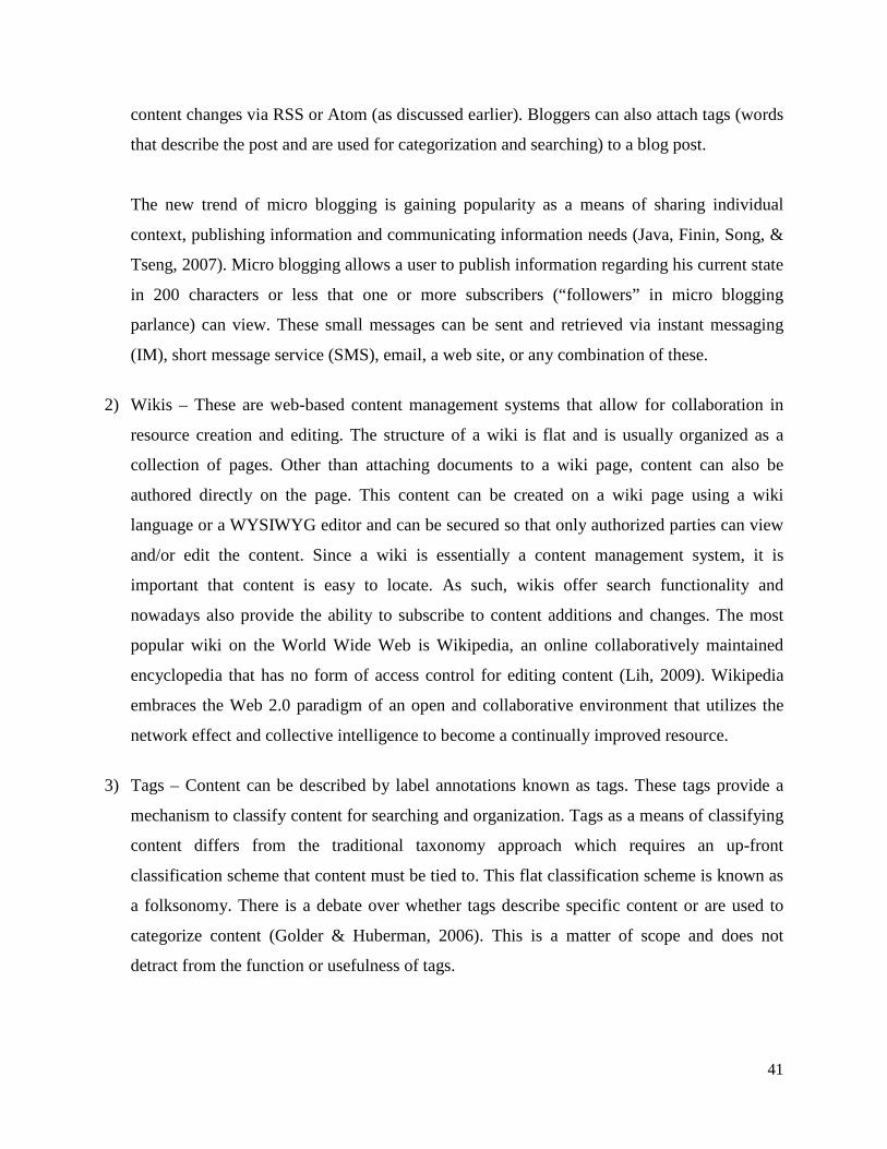
41
content changes via RSS or Atom (as discussed earlier). Bloggers can also attach tags (words
that describe the post and are used for categorization and searching) to a blog post.
The new trend of micro blogging is gaining popularity as a means of sharing individual
context, publishing information and communicating information needs (Java, Finin, Song, &
Tseng, 2007). Micro blogging allows a user to publish information regarding his current state
in 200 characters or less that one or more subscribers (“followers” in micro blogging
parlance) can view. These small messages can be sent and retrieved via instant messaging
(IM), short message service (SMS), email, a web site, or any combination of these.
2) Wikis – These are web-based content management systems that allow for collaboration in
resource creation and editing. The structure of a wiki is flat and is usually organized as a
collection of pages. Other than attaching documents to a wiki page, content can also be
authored directly on the page. This content can be created on a wiki page using a wiki
language or a WYSIWYG editor and can be secured so that only authorized parties can view
and/or edit the content. Since a wiki is essentially a content management system, it is
important that content is easy to locate. As such, wikis offer search functionality and
nowadays also provide the ability to subscribe to content additions and changes. The most
popular wiki on the World Wide Web is Wikipedia, an online collaboratively maintained
encyclopedia that has no form of access control for editing content (Lih, 2009). Wikipedia
embraces the Web 2.0 paradigm of an open and collaborative environment that utilizes the
network effect and collective intelligence to become a continually improved resource.
3) Tags – Content can be described by label annotations known as tags. These tags provide a
mechanism to classify content for searching and organization. Tags as a means of classifying
content differs from the traditional taxonomy approach which requires an up-front
classification scheme that content must be tied to. This flat classification scheme is known as
a folksonomy. There is a debate over whether tags describe specific content or are used to
categorize content (Golder & Huberman, 2006). This is a matter of scope and does not
detract from the function or usefulness of tags.

42
Tags are used to promote another Web 2.0 phenomenon known as Social Bookmarking
whereby individuals publish hyperlinks to information resources that they deem as worth
sharing onto a social bookmarking web site. These web site links are annotated by tags and
comments and foster a community pool of knowledge to be shared (and further annotated) by
acquaintances of the poster or anyone else that belongs to the social bookmarking site
community (Smith, 2008).
Tag clouds visually show the popularity of a group of tags on a web site by showing tags in
different sizes based on the number of times content was labeled with a specific tag. Clicking
on a tag in the cloud typically invokes a search that retrieves a list of all content that is
associated with that tag so that a user can locate specific information. A sample tag cloud is
illustrated in Figure 2.3.
Figure 2.3: A sample tag cloud (retrieved from: http://en.wikipedia.org/wiki/Tag_cloud, retrieved: 2012-01-04)

43
4) Mashups – Like most of the new Web 2.0 technologies and applications, mashups are a
combination of several other technologies that deliver a brand new application paradigm.
Mashups are custom, ad hoc applications that are constructed (often by non programmers) by
unifying a combination of data, user interface components, processes and services (Hanson,
2009). Technologies such as REST, RSS/Atom, XML, HTML and HTTP facilitate the
creation of these typically situational applications. The power behind mashups is their ability
to aid in the extensibility of an application by mixing data and functionality in unforeseen but
legitimate ways. If mashups are constructed utilizing the assets of a Service Oriented
Architecture (SOA), their creation and deployment should be governed and best practices
borne in mind (Ogrinz, 2009). This will assist in mitigating any negative consequences of
employing mashup technology (Bernal, 2009).
Mashups are giving rise to a new application paradigm inside the organization known as
situational applications. Situational applications are developed (or rather assembled) and
deployed by end users without the need to involve corporate IT departments (Cherbakov,
Bravery, Goodman, Pandya, & Baggett, 2007). These applications are not required to be of
enterprise standard in terms of, for instance, scalability and failover and are assembled
rapidly to solve specific business needs.
5) Rich Internet Applications (RIA’s) – The need for a richer user interface experience and the
ability for a user to store information locally and work in an occasionally connected (to the
internet, intranet or extranet) environment has prompted the development of rich internet
applications. Rich internet applications allow web applications to behave more like familiar
traditional desktop based applications. AJAX, as discussed earlier allows for a richer user
interface by utilizing JavaScript in the browser to refresh only the portions of a web page that
have changed as opposed to subjecting the user to a complete page refresh. AJAX itself does
not facilitate offline data storage for occasionally connected users but this need is being
addressed by the new HTML 5 specification. User interfaces based on the Flash runtime such
as Adobe Flex (http://www.adobe.com/products/flex), Adobe AIR
(http://www.adobe.com/products/air) and OpenLazlo (http://www.openlaszlo.org) allow for
very rich user interfaces and the ability to store information on the local system thereby

44
allowing for offline access to applications. These user interfaces however require an initial
download of the application to the user’s computer as well the requirement that a supporting
runtime (Flash or AIR in this case) be present. Other vendors including Oracle and Microsoft
have seen potential in the rich internet application arena and have released their own products
in this space: JavaFX (http://www.oracle.com/technetwork/java/javafx/index.html) and
Silverlight (http://msdn.microsoft.com/en-us/silverlight/bb187358.aspx) respectively.
What I have discussed in this section is summarised in Figure 2.4. It illustrates how the Web 2.0
paradigm and related technologies, applications and techniques are related.
Strategic positioning:
• The web as a platform
User positioning:
• You control your own data
Core competencies:
• Services, not packaged software• Architecture of Participation• Cost-effective scalability• Remixable data source and data transformation• Software above the level of a single device• Harnessing collective intelligence
Flikr, del.ici.ous, Tagging, not taxonomy
Gmail, Google Maps and AJAX: Rich User
Experiences
“As attitude, not a technology”
PageRank, eBay Reputation, Amazon
reviews: User as contributor
Google AdSense: customer self-service enabling the long tail
Blogs: Participation, Not publishing BitTorrent: Radical
Decentralization
Wikipedia: Radical Trust
The long tail
Data as the “Intel inside”
Hackability
The perpetual beta
The right to remix: “Some rights
reserved”
Software that gets better the more people
use it
Emergent: User behaviour not predetermined
Play
Granular Addressability of
content
Rich User Experience
Small Pieces Loosely Joined (Web as components)
Trust your users
Figure 2.4: Web 2.0 Meme Map (O'Reilly, 2005)

45
2.5.1.3 Aggregating Web 2.0 applications: web portals
The technology enablers in the previous section provide the building blocks for constructing rich,
interactive applications for end users. What is required is a platform that brings all the
applications together into a single user interface, with functionality such as navigation,
authentication (is the user allowed to use the portal?), authorization (what information the user is
allowed to view or what functionality they can access), personalization and customization. The
last two features will be explained in more detail.
Personalization and customization are used interchangeably in both commercial and academic
circles (Treiblmaier, Madlberger, & Knotz, 2004). I chose to describe the terms using the
definitions provided by Jakob (1998). Personalization refers to the manner in which the portal
alters its appearance or functionality based on the attributes of the user or the user’s previous
behaviour, according to parameters defined by the custodians of the portal. Customization refers
to functionality provided to end users that will enable them to adjust the appearance and
functionality of the portal and its content. The level of customization is a factor of both the portal
product and the portal custodian’s discretion.
Web portals are the platforms that provide this content aggregation, navigation, security,
personalization and customization. Portals consist of portal pages, each of which contains one or
more portlets. A portlet can be viewed as a web application bounded by a window that allows the
portlet to be visually separated from other portlets on the same page, and the portal itself (Sarin,
2011). In addition, the window might provide the facilities to allow the portlet to be maximized
(increased in screen size), minimized (decreased in screen size), customized in terms of
functionality, or allow for the display of help information on using the functionality provided by
the portlet. Portlets can be of several types: portlets can be purely content related, they can
contain specific functionality or they can be generic applications (such as wiki’s, blogs and
forums).
Portlets might run natively on the same server as the portal server itself or alternatively the
portlet might be remotely rendered inside the portal (on the portal page) using the Web Service
for Remote Portlets (WSRP) protocol (Wege, 2002). WSRP allows functionality, deployed as a
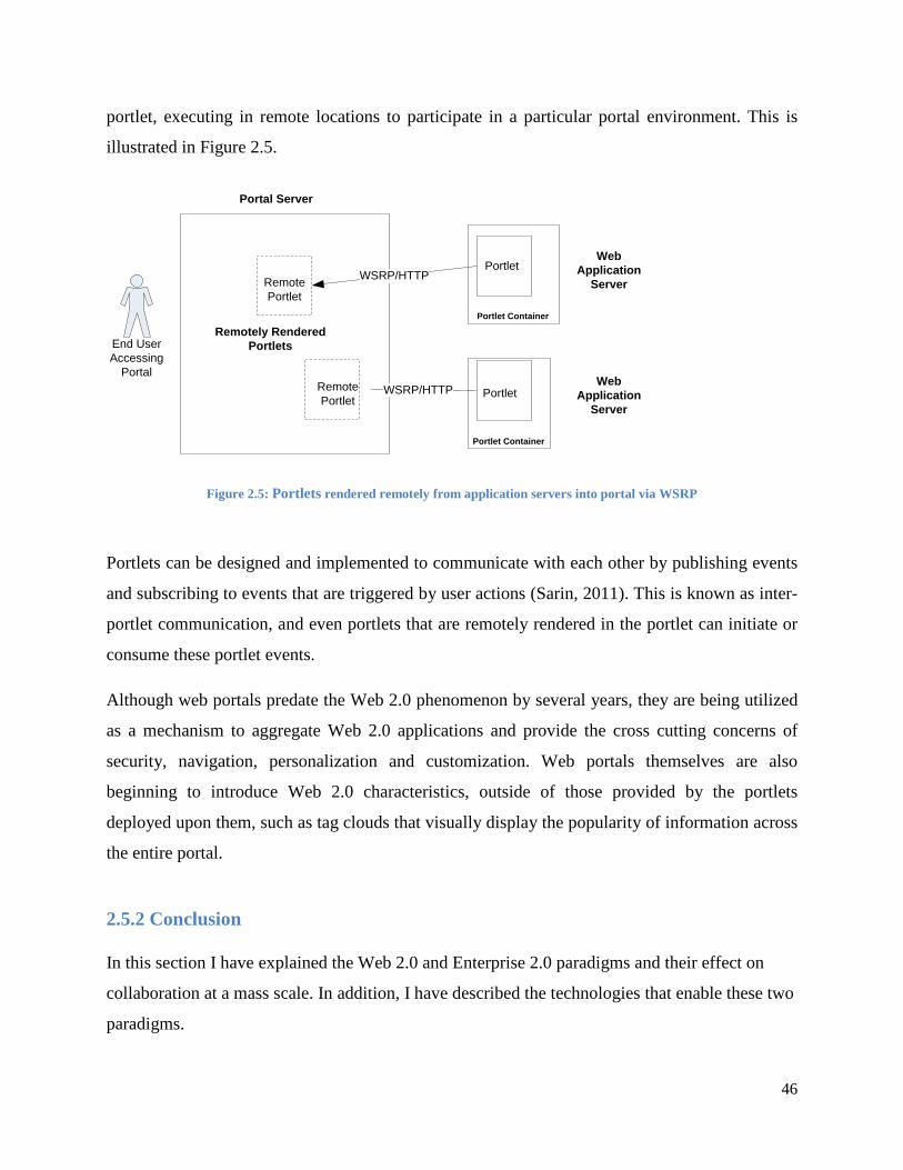
46
portlet, executing in remote locations to participate in a particular portal environment. This is
illustrated in Figure 2.5.
End UserAccessing
Portal
WSRP/HTTP
WSRP/HTTP
Portal Server
Portlet
Portlet
RemotePortlet
RemotePortlet
Web Application
Server
Web Application
Server
Portlet Container
Portlet Container
Remotely Rendered Portlets
Figure 2.5: Portlets rendered remotely from application servers into portal via WSRP
Portlets can be designed and implemented to communicate with each other by publishing events
and subscribing to events that are triggered by user actions (Sarin, 2011). This is known as inter-
portlet communication, and even portlets that are remotely rendered in the portlet can initiate or
consume these portlet events.
Although web portals predate the Web 2.0 phenomenon by several years, they are being utilized
as a mechanism to aggregate Web 2.0 applications and provide the cross cutting concerns of
security, navigation, personalization and customization. Web portals themselves are also
beginning to introduce Web 2.0 characteristics, outside of those provided by the portlets
deployed upon them, such as tag clouds that visually display the popularity of information across
the entire portal.
2.5.2 Conclusion
In this section I have explained the Web 2.0 and Enterprise 2.0 paradigms and their effect on
collaboration at a mass scale. In addition, I have described the technologies that enable these two
paradigms.

47
Despite the excitement of Web 2.0 and the proposed opportunities for collaboration there are
those that question the supposed paradigm shift and the innovation of its associated technologies.
I will address these arguments next.
2.6 A critique of Web 2.0
Web 2.0 as a phenomenon is not without detractors, the most notable being the father of the
World Wide Web, Berners-Lee. In an interview conducted by IBM via podcast with Berners-
Lee, a question was posed about whether Web 1.0 was about connecting computers while Web
2.0 was about connecting people (IBM, 7-28-2006). Berners-Lee answered that the Web, from
its origins, was always about connecting people and facilitating communication. He dismisses
the term Web 2.0 harshly as jargon saying that nobody “even knows what it means” (IBM, 7-28-
2006). He further contends that the original web technologies (HTTP, HTML, JavaScript and
hyperlinking) have always existed and are just being used in different combinations to enhance
the user’s experience.
Some scholars see the Web 2.0 meme as not only vague in its definition, but also as a marketing
tool employed with the hope of selling software and services (Scott, 2009). Scott elaborates that
Web 2.0 is primarily built on the same technologies as Web 1.0 and that any new technologies
are not as evolutionary as they are made out to be. He therefore contends that the term Web 2.0,
itself, is misnamed and misleading. Finally, he also warns of a Bubble 2.0 where, like the dot
com crash of the earlier twenty first century, a similar bubble could emerge by companies
establishing themselves on hype and marketing without any solid business plans.
No matter how Web 2.0 technologies and services are described (or indeed marketed) there have
been tangible improvements that end users can experience when interacting with Web 2.0 web
sites. Services and techniques such as blogs, wiki’s and social networking are not particularly
groundbreaking when compared to their Web 1.0 counterparts although they are much more
accessible and user-friendly (Yakovlev, 2007). Yakovlev does however see the following
technologies as more revolutionary:
48
1) Mashups – The ability to combine data and functionality from multiple sources into new
applications was not easy to achieve previously without the aid of professional programmers.
This ability is now in the hands of the end users which provides value and decreases costs.
2) Folksonomies – It is now possible to find information based on how other people using the
system have classified information and on what has been previously searched for. The need
for upfront content classification schemes has been decreased.
3) Really Simple Syndication – In the past, there was no standard mechanism to send users a
notification of changes to content in which they were interested.
Despite the criticisms leveled at the Web 2.0 paradigm, the excitement and exponential adoption
of everyday users have sparked interest in utilizing these technologies inside organizations. As
Web 2.0 technologies have matured they are finding their way into the enterprise with the hopes
of improving collaboration, productivity and ultimately, profitability.
2.7 What is Enterprise 2.0?
Not long after Web 2.0 applications started appearing on the internet, two things began to happen
to the organization. Firstly, users wanted the same types of web applications in terms of
functionality and usability to be available for their day-to-day work. Secondly, the management
of organizations began to wonder if the advantages and successes of Web 2.0 could be emulated
in their own environments (Newman & Thomas, 2009). Enterprise 2.0 is this implementation of
the Web 2.0 paradigm and associated technologies inside the organization (McAfee, 2006).
Enterprise 2.0 rollout and adoption is typically from the bottom up: seldom does an organization
roll out an application like a wiki for adoption by the entire enterprise. What typically occurs is
that a few employees install and utilize Web 2.0 technologies and the adoption becomes viral as
other individuals become aware of the advantages this collaborative technology can bring to their
day-to-day work (Newman & Thomas, 2009).
McAfee (2006) proposes the following conceptual components that are necessary for system to
facilitate the activities of an organization’s knowledge workers:

49
1) Search – A content indexing and searching mechanism should be provided that locates
content based on keyword searches.
2) Links – The ability to create content that is accessible via a link and that this content itself
links to related material aids in organizing and finding information.
3) Authoring – Platforms such as blogs allow for content publishing that grows in value as other
individuals contribute content to the original posts and comments. WYSIWYG editors should
be provided to allow for easy content authoring without the need to learn a platform-specific
language.
4) Tags – The ability to add short descriptions (typically a single word) to content allow for
better categorization, searchability and navigation of the collaboration system. The tag
system results in a folksonomy (categorization and structure of content by users over time) as
opposed to a taxonomy (content is added to a predefined structure).
5) Extensibility – It should be possible to add not only content but also subcomponents without
the need to program. In addition, data from sources outside of the system should be
consumable.
6) Signals – Emails, or nowadays, syndication mechanisms such as Really Simple Syndication
(RSS), should be utilized to inform individuals of changes or additions to content to which
they have subscribed.
These conceptual components are collectively referred to by the “SLATES” acronym. Later in
this chapter I will map these components to specific Web 2.0 technologies in order to formulate
the technical requirements that a collaboration system must implement.
Much like CSCW systems, Enterprise 2.0 implementations are having a profound effect on the
way individuals and groups in the organization perform their daily tasks. When information is
more easily accessible and locating and utilizing individuals with expertise in order to
collaborate on projects is a reality, the traditional top-down hierarchy in an organization is no
longer as relevant (Tapscott, 2006). What is important is peer-to-peer collaboration that can take

50
place almost effortlessly even in large multinational organizations thus crossing the boundaries
of time and space.
2.8 Web 2.0 collaboration applications versus Computer Supported Cooperative
Work Systems – substitute or complementary?
At first inspection there seems to be a number of differences between Computer Supported
Cooperative Work (CSCW) systems, or groupware, and social systems as embodied in Web 2.0
applications (Koch, 2008). These include:
1) The focus on the individual in Web 2.0 versus the focus on the group in groupware. Web 2.0
application users utilize the applications for self fulfilment and by doing so create value by
network effects almost as a side effect. Users of groupware systems are conscious of the fact
that they are working on a system with others for the benefit of the group.
2) Groupware systems are sponsored and implemented in a top-down fashion by management.
Web 2.0 systems are utilized voluntarily and their use by others is viral in nature (bottom-up
adoption).
3) Groupware systems are designed to achieve specific objectives. These objectives are
typically defined by management. Web 2.0 systems are not designed ahead of time in a way
that makes them complete. The user community is actively involved in the way the system
evolves over time as they dictate their wants and needs.
4) Groupware systems are not designed or built to support the same mass of users that Web 2.0
applications are expected to attract. With the proliferation of the internet into almost every
facet of daily life and its impact on the organization, this is becoming increasingly less true.
Figure 2.6 further illustrates the differences between the field of CSCW, the application of
CSCW in the form of groupware applications and Web 2.0 (Prilla & Ritterskamp, 2008). The
field of CSCW is concerned with the theory of groups and how they perform work activities.
Groupware applications apply this theory to the creation of applications that facilitate
communication and coordination between individuals and groups. Web 2.0 applications are more

51
focused on the user experience with communication, coordination and collaboration being the
result of interacting with the application.
Groupware
CSCW Web 2.0
WikisTagsBlogs
Communication &Coordination
Goal & WorkOrientation
Playfulness &User
Experience
Figure 2.6: Distinguishing between groupware, CSCW and Web 2.0. Adapted from Prilla & Ritterskamp
(2008)
Web 2.0 applications have succeeded in providing the collaboration platform that was always
desired by the designers of groupware systems while at the same time overcoming the difficulties
and limitations often inherent in these systems (Prilla & Ritterskamp, 2008). Some of the
advantages of Web 2.0 applications over their groupware counterparts include rich and
responsive user interfaces and open systems architectures that facilitate extensibility. These
advantageous aspects of Web 2.0 applications encourage users to collaborate, contribute content
and demand additional features leading to increased value by virtue of network effects.
Koch (2008) believes that a lesson that CSCW system designers can learn from Web 2.0 systems
is that not all requirements have to be thought up in advance. Rather provide a sufficient system
to the users and let them determine the future path the system will take. On the other hand, he
argues that while the field of CSCW can benefit from the technologies employed by Web 2.0

52
applications, the Web 2.0 system designers can learn from the theories formulated by CSCW in
terms of group dynamics and organization requirements. Therefore the infant field of Web 2.0
can benefit from the theoretical understanding based on many years of research in the
multidisciplinary field of CSCW.
What is evident from this discussion is that the fields of CSCW and Web 2.0 are not at odds with
each other. Each field adds valuable contributions that, if combined, will be to the benefit of
both.
2. 9 Functional requirements for constructing a modern collaboration system
Despite the inherent limitations with traditional collaboration systems such as groupware, much
can be learned from the CSCW research. The results of this research should be the foundation for
functional requirements of a modern collaboration system. In addition, the fundamental tenets of
Web 2.0 have to be incorporated into the results of this research to obtain the final list of
requirements.
Reviewing the CSCW research (Mandiviwalla & Olfman, 1994; Hoscka, 1998; Grudin, 1988)
and unifying this with the Web 2.0/Enterprise 2.0 paradigm (Koch, 2008; McAfee, 2006,
O’Reilly, 2005) yield the following list of functional requirements:
1) Individuals should be able to publish and edit content with ease. Users should have access to
web-based WYSIWYG editors in order to add or edit content. A user should not have to
learn the syntax or semantics of a publishing language.
2) Published content should be structured through meta-data. The ability to add descriptive
terms allows content to be organized and searched.
3) Published material should be enriched via comments and links to related content. Other
individuals should be allowed to publish their comments on published content. Meta-data
should allow for “click through” to related content.

53
4) It should be possible to subscribe to a notification mechanism that will inform a user of new
or amended content. These notifications should be via multiple mechanisms such as
syndication or email, depending on the user’s preferences.
5) Content should be searchable. The published content as well as the attached meta-data should
be included in the target of any searching mechanism.
6) Users should be able to make additions to the system itself, with little or no knowledge of
how to program. The ability to add predefined functional subcomponents (such as a user
interface widget) to the current system should be possible without the need to program.
7) Published content of a sensitive nature should be available only to authorized individuals. It
should be possible to restrict access to content as appropriate.
8) The system should allow for simple management of user groups. The modern organization is
fairly flat yet evolves its structure in order to reach predefined goals and strategies. As such,
it should be simple for the user groups as defined in the system to change as the
organizational structure does.
9) Interaction between individuals using the system should also support real-time
communication. Although notification of added or changed content is useful, mechanisms
such as instant messaging, video-conferencing and shared workspaces should be provided to
allow users to interact and share information in real-time.
The technology required to support the implementation of these functional requirements is
available under the Web 2.0 umbrella, that views the internet as platform (Musser & O'Reilly,
2007).

54
2.10 Technology requirements for constructing a modern collaboration system
In the earlier explanation of Enterprise 2.0 (Section 2.5.3) I described McAfee’s (2006) SLATES
components necessary for implementing a collaboration platform for knowledge workers. In the
list below I map these conceptual components to technology, particularly in the Web 2.0 space
(Section 2.5.1.2), in order to define the technical requirements for the collaboration system under
study.
1) Search – The user must be capable of searching for artefacts of interest such as documents
and people with required expertise. The system must allow for keyword searches that search
across the entire site. The search mechanism must search not only artefact content but also
against keywords (tags) assigned to content users. Tag clouds also facilitate locating artefacts
and must therefore also be provided by the system.
2) Links – All content must be addressable via a distinct Universal Resource Locator (URL).
This facilitates hyperlinking between resources and facilitates remixing content and function
via REST to create all new functionality.
3) Authoring – The system must support user generated content. All this user generated content
must be searchable and allow for fine grained access control. Authoring should allow for
WYSIWYG editing so that a user can utilize a familiar mechanism for adding or altering
content without having to learn a system specific language.
4) Tags – User-contributed keywords attached to artefacts stored on the system assist with
classifying and locating resources. Tags are a classification system known as a folksonomy
which is driven by the community using the system. This is in stark contrast to traditional
classification systems which are predefined and imposed in a top-down manner
(taxonomies). Tags tend to add value over time (via network effects) as more people classify
resources.
5) Extensibility – This concept is related to authoring. It must be possible for a user to extend
the system’s value not only by adding content but also by extending system functionality.
Breaking a system into components with defined REST-based interfaces should allow the

55
system to be extended by end users without any programming knowledge. This is done by
creating mashups and situational applications as needs arise or the organization evolves.
6) Signals – Automatic notification to users when content changes (or any other events that are
significant to the users of the system) via email, or newer syndication mechanisms such as
Really Simple Syndication (RSS) and Atom should be provided. Users should be able to
decide to which events they wish to subscribe. Notification mechanisms provide users with
awareness of what is happening on the system when they are offline. Lists such as those
illustrating latest content updated, or the showing the currently logged in users further aid in
awareness.
Mapping the SLATES components to specific technologies helps to ensure that we do not apply
Web 2.0 technologies without considering the functional requirements of a collaboration system.
2.11 Implementing a collaboration platform for the enterprise
As previously mentioned, CSCW systems are socio-technical in nature. Socio-technical systems
differ from traditional systems whose primary objective is to transform input into output. The
technical and social aspects of the system (how the system will function in the group, or social
system where it is introduced) have to be considered in combination when designing a CSCW
system (Koch, 2008). This is because the introduction of such a system alters the manner in
which individuals perform their day-to-day work activities.
The technical concerns when introducing a system into an organization revolve around the
physical infrastructure required to implement and operate the system. Traditionally, applications
are hosted on the premises of the organization. The implications of this approach are many.
On site hosting of applications requires that the IT operations personnel have the skills to install
and maintain the necessary hardware, operating systems, application servers and databases that
the application will require to function. Additionally, requirements in terms of scalability and
availability require forethought and can be costly (Eeles & Cripps, 2010).

56
An alternative to hosting the system on premise is to utilize cloud computing. Cloud computing
is the result of an evolution in hardware, networks and software that, like Web 2.0, has grown
out of the progression of the internet and its associated technologies. Cloud computing can
simply be defined as a platform that has the following characteristics (Rosenberg & Mateos,
2010):
1) A collection of computing resources that is available when needed.
2) These computing resources are only utilized when they are required.
3) These computing resources can be assigned dynamically to allow for (almost) unlimited
scalability.
The above is akin to the Just-In-Time paradigm adopted for resources in the supply chain
management discipline made popular by companies like Toyota (Benefield, 2009).
Furthermore:
1) The billing of resource utilization is on a per usage basis.
2) Access to the cloud is typically via a web browser or web service API.
3) Provisioning and configuration of computing resources require no human intervention.
4) Often, but not always, the computing resources are not on the premises of the organization
utilizing the cloud computing platform.
To better understand cloud computing it is important to describe the various cloud computing
layers and the services offered at these layers.
2.11.1 Cloud computing layers and services
The layers of cloud computing map onto those of traditional enterprise software applications as
illustrated in Figure 2.7.

57
InfrastructureServices
PlatformServices
ApplicationServices
Figure 2.7 - The layers of cloud computing. (Copied from Amrhein & Quint 2009)
These layers segment the services offered in the cloud computing paradigm (Rosenberg &
Mateos, 2010):
Infrastructure services
Infrastructure as a Service (IaaS), also known as Hardware as a Service (HaaS) is the most
coarsely grained service offering where assets such as servers, operating systems and storage
space are made available on demand. The infrastructure required can be commissioned from
prebuilt virtual images or customized according to requirements.
Platform services
Platform as a Service (PaaS) provides the base on which business applications can be built. This
base is in the form of languages and frameworks that utilize the infrastructure layer below to
enable business applications built on the platform layer to scale as required. Examples of
platform services include Google App Engine (http://appengine.google.com/ ) and Microsoft
Azure (http://www.microsoft.com/windowsazure/).

58
Application services
Software as a Service (SaaS) provides a user or organization with a business application
accessible via a web browser (or mobile device) without the user having to install any
application software on their local device. These software services range in purpose from
Customer Relationship Management (http://www.salesforce.com) to business collaboration
solutions (http://www.ibm.com/cloud-computing/social/us/en/).
All of the above service offerings provide benefits in terms of lower capital and operating
expenses, increased availability and scalability and faster time to market. However, this must be
measured against the lack of customization, particularly as we move further up the layers.
2.11.2 Cloud computing deployment models
There are several cloud computing deployment models as illustrated in Figure 2.8.
Figure 2.8 - Cloud computing deployment models (Copied from Amrhein & Quint, 2009)
Public clouds
These are offerings hosted and managed entirely by a third party and exist outside of the
organization’s firewall.

59
Private clouds
Service offerings are hosted and managed by the organization inside their firewall. Some authors
dispute whether private clouds are truly cloud-based. This is because private clouds often do not
provide the almost unlimited scalability provided by public clouds because they are limited by
the resources available in the organization’s data centre (Reese, 2009).
Hybrid clouds
These are a combination of public and private clouds. Any combination of services and/or
infrastructure can exist on the organization’s premises or on a public cloud. This is the newest
deployment model and deemed the most complex as governance and integration are inherently
difficult (Amrhein & Quint, 2009).
Cloud computing is a viable alternative to local hosting when delivering a collaboration platform
to the enterprise. There are many aspects and alternatives to consider to ensure that this approach
is a right fit for the organization.
I will now discuss the limitations of traditional collaboration software when applied to the
process of software development.
2.12 Limitations of current collaboration solutions in the software development process
A review of the literature has reaffirmed that collaboration is an essential requirement in the
creation of software systems. This is regardless of whether the development of systems is done
by a small collated team or undertaken by a large distributed workforce.
Earlier work done in the multidisciplinary field of CSCW resulted in the implementation of
CASE tools to facilitate software development that met with limited success.
I have noted the following shortcomings with the platforms and tools provided to aid in the
collaboration of enterprise software:
1) There are no solutions that provide a single interface across all the phases of the SDLC. It
should be possible to assess a project’s status and view all related artefacts (such as

60
specifications, configuration management documents and even source code) from a single
entry point. Current solutions focus on views, reports and other artefacts for only one (or a
few) phases of the SDLC – this serves to segment stakeholders based on their role and
eliminate the benefits of true SDLC crosscutting collaboration.
2) No solutions allow for the effective collaboration of all stakeholders in the SDLC. Current
collaboration mechanisms such as email, instant messaging (IM) and wiki’s are disjoint from
a platform that manages all the artefacts created and maintained during the SDLC.
3) Platforms for collaboration in the software development process are primarily “pull” in
nature: it is up to a stakeholder to discover how the project is progressing and what artefacts
have changed. I propose a subscription-based mechanism that will automatically notify
interested stakeholders, in the medium of their choice, of updates to the project progress and
artefacts as well as any relevant communication that has occurred.
4) Current software collaboration systems suffer from poor personalization. Views into the
project should be personalized based on the logged in stakeholder’s role to ensure they view
information relevant to their interests and concerns.
5) Collaboration systems are either not extendable or extensions are difficult and costly. This
issue is closely tied to the issue of the organization’s adaption when the new system is
introduced. A collaboration platform should adapt to the structures and processes of the
organization into which the system is introduced. It is impossible to predict with certainty
how any system will need to change in order to facilitate the changing needs of an
organization as time progresses. From a technical perspective, the system platform should be
constructed using open standards and technologies that can allow the organization to grow or
alter the system over time in order to meet new or changing demands.
Important lessons I have learned from studying the field of CSCW are that the social aspects of
the platform, due to the nature of the social system (the organization and the groups operating
inside the organization) where the platform will be deployed cannot be ignored and must be
given attention during design and implementation. The organization and the system are going to

61
co-adapt since the system changes the manner individuals and groups operate and the way the
organization, its structure and goals evolve over time. Finally, the system needs to be designed
and implemented so that it becomes a seamless part of all users’ day-to-day activities. If this is
not the case, the collaboration system will become part of a disjoint, jumping between multiple
application scenarios that will most likely result in poor adoption. Maximum adoption of the
platform is vital for the system to bring true value to the organization by virtue of network
effects.
Understanding the lessons learned from the multidisciplinary field of CSCW in conjunction with
the principles and technology enablers of the Web 2.0 paradigm and applying these to the
collaboration requirements of software development can result in an architecture for a
collaboration platform that will assist in the creation of quality enterprise software.
2.13 Summary and conclusion
This chapter has described why collaboration in the enterprise is important for achieving
strategic and operational objectives. My particular focus has been on the importance of
collaboration for the creation of enterprise software. Software development is inherently a
collaborative activity that requires a large amount of communication and coordination between
stakeholders in order to achieve a successful outcome (Lee & Shiva, 2009).
Early research in the multidisciplinary field of CSCW gave rise to CASE tools to support the
software development process. These tools have met with limited success for a number of
reasons. The increase in size and complexity software coupled with the distributed nature of
software development, partly due to economic factors, has fueled the need to find ways to
facilitate collaboration in the arena of software development.
At the same time the philosophies and enabling technologies of Web 2.0 and Enterprise 2.0 have
emerged as possible solutions that can aid in the collaboration required to construct successful
software systems.
I contend that it is possible to formulate an architecture for a Web 2.0 based collaboration
platform that will assist in the successful development of enterprise software systems. This
architecture will embrace the lessons learned from the field of CSCW and marry those with the

62
philosophies and technology enablers of the Web 2.0 paradigm. The result will be a collaboration
platform architecture that is open and extensible in terms of technology and processes and will
adapt to the organization’s structure and requirements.
I hope that the proposed architecture will facilitate a physical implementation that can then be
further studied using positivistic research techniques to assess whether such a system will add
measurable value to the construction of enterprise software.
In the next chapter I will describe how I conducted my research study in order to produce the
platform architecture.
63
Chapter 3: Research design and methodology
3.1 Introduction
The purpose of this chapter is to outline the scientific foundation for the research that was
conducted. Only through thorough and unbiased means can any contribution to academia be truly
meaningful. Therefore, it is important to clearly define what the objects of study were and to
elaborate on the methods that were employed to conduct the study.
The research questions investigated were:
1. What are the functional and non-functional requirements for an architecture to support the
collaboration requirements throughout the complete SDLC?
2. What should an architecture for the construction of a collaboration platform to assist the
production of enterprise software (and that fulfil the requirements identified in 1 above) look
like?
In this chapter I will begin by briefly discussing the various research philosophies in order to
make it clear why I selected the design science research paradigm for conducting my research. I
will then describe the research strategy that I employed and will conclude this chapter by
presenting the research method that was followed in conducting my research.
3.2 Research philosophy
In this section I will describe the different research philosophies and explain why the selected
philosophy was chosen for the purposes of my research.
3.2.1 Research philosophy background
Research is the activity that is undertaken to understand some phenomenon that occurs naturally
in the real world, or one that is constructed (Vaishnavi & Kuechler, 2009). These research
activities involve the application of appropriate research methods in order to gain an
understanding of the phenomenon (Hevner & Chatterjee, 2010).

64
Any research undertaken is based upon several beliefs that determine whether the research is
valid and what methods should be employed in order to conduct the research (Vaishnavi &
Kuechler, 2009):
1) Ontological assumptions – How reality is viewed by the researcher. Is there a single
objective reality, is reality separately constructed by the observer and research participants or
is reality the building of an artefact of some utility?
2) Epistemological assumptions – How the researcher views the nature of knowledge and his
beliefs on how well any phenomenon can really be known or understood.
3) Axiological assumptions – The nature of the value that the researcher would like to achieve
by conducting his research.
4) Methodological assumptions – The activities, practices and procedures that the researcher
will undertake to conduct his research.
A research paradigm appropriate for a specific research community is the combination of the
above four assumptions (Hevner & Chatterjee, 2010). The specific research paradigm determines
the way the researcher sees the world under study as well as the nature of the knowledge
obtained by conducting the research. The research paradigm also dictates what the desired
outcome of the research must be and as a consequence what specific method(s) must be applied
to reach those goals.
Some of the basic research paradigms include the following (Vaishnavi & Kuechler, 2009):
1) Positivistic research – An unbiased researcher observes a stable and measurable single
reality. The results of the research are quantifiable and these results can predict future
behaviour. Positivistic research utilizes quantitative and experimental methods to test a
theory or hypothesis (Marczyk, DeMatteo, & Festinger, 2005).
2) Interpretative research – The researcher studies multiple realities that are socially
constructed. In interpretative research, the researcher realizes his subjective biases and
acknowledges that he is a participant in what is being observed. Qualitative means are used
to gather and analyse relevant information (Durrheim, 1999).

65
3) Design science research – The researcher attempts to solve a problem in an organization by
the construction of an appropriate artefact. This is done in an iterative fashion by the constant
evaluation of the artefact’s usefulness when applied to the identified need.
Table 3.1 summarizes the philosophical assumptions of the three research paradigms.
Table 3.1: Philosophical beliefs of the three research paradigms adapted from Vaishnavi & Kuechler (2009)
Research Perspective
Philosophical Belief Positivist Interpretive Design Science
Ontology Single Reality; Knowable; Probabilistic
Multiple realities; Socially constructed
Multiple contextually situated realities; Socio-technologically enabled
Epistemology Objective; Detached observer of the truth
Subjective: values and knowledge emerge from the researcher-participant interaction
Knowing through making; Objective context-based construction; Iterative
Methodology Observation; Quantitative and statistical
Participation; Qualitative
Developmental; Measure artefactual impacts on the current system
Axiology Universal truth; Prediction
Based on researcher’s values and biases; Understanding contextually based
Control; Creation; Continuous improvement; Understanding
I will now discuss which one of the above three research paradigms I selected for my study and
the reasons for this decision.

66
3.2.2 Research philosophy applicable to my study
The purpose of the study was to define the architecture of a collaboration platform that will
facilitate the creation of enterprise software. This collaboration platform is the result of the
application of the multi-disciplinary theory of Computer Supported Cooperative Work (CSCW)
with the concept and associated technologies of Web 2.0. The nature of this study lends itself to
the design science research paradigm for a number of reasons:
1) Ontological assumptions – The study addresses the needs of organizations that have a
requirement to construct enterprise software. The construction of enterprise software requires
the collaboration of many diverse (possibly geographically dispersed) stakeholders. There are
therefore multiple contextually situated realities that are technologically enabled (Vaishnavi
& Kuechler, 2009). My study involves the creation of an architecture for a collaboration
platform to assist organizations in constructing software systems.
2) Epistemological assumptions – The creation of a software architecture is iterative by nature
(Rozanski & Woods, 2012). Each successive iteration builds on the knowledge gained from
evaluating the outcome of the previous iteration. This process results in a knowledge gain
about the problem and solution domains through the iterative construction and evaluation of
the architecture.
3) Methodological assumptions – A software architecture is a construction activity that
identifies the components of the system as well as the interactions of the subcomponents
(Eeles & Cripps, 2010). Although several possible architectures can fulfil the functional and
non-functional requirements, there are objective means of determining whether one
architecture is more suited than another by balancing the trade-offs in terms of cost,
resources and time to market (Bass, Clements, & Kazman, 2013). A way of determining
whether an architecture is more suitable than other candidate architectures is by evaluating
the architecture against a set of scenarios that describe how the system will be used. The
scenarios that I evaluate my architecture against are described in Chapter 5.
4) Axiological assumptions – The creation of an architecture for a collaboration platform of this
nature is only possible by the understanding of the problem domain (collaboration required

67
during the construction of enterprise software). The understanding of the problem domain
results in the identification of functional and non-functional requirements for the desired
platform. This understanding moves us from the problem space to the solution space and
only then can the iterative nature of constructing the platform’s architecture commence. Each
iteration of the process of creating the architecture increases our understanding of both the
problem and the solution domains as we learn by doing. The result of this is a constantly
improving architecture that better addresses the organization’s needs.
Given the discussion in the preceding section it is clear that the design science research paradigm
is the most appropriate for this study.
It is important to distinguish between design science research and the more every day design
effort and explain why my study falls within the realm of the former. The usual design effort
takes place using existing knowledge and practices to construct an artefact. Design science
research, on the other hand, is the design and construction of artefacts where there are unknowns
and existing knowledge and practices do not yet exist or are inadequate. The resulting artefact,
and in some cases, the process used to construct it, contributes knowledge that will in future aid
the more pedestrian design efforts for systems of a similar nature (Vaishnavi & Kuechler, 2009).
My study, to architect a collaboration platform for the development of enterprise software
(FeatureIT), takes knowledge from the field of CSCW and marries this with the technologies and
principles of the Web 2.0 paradigm in a way not previously done. Combining CSCW theory with
Web 2.0 results in a platform that addresses many of the shortcomings of previous CSCW
system instantiations.
Before I leave this section I would also like to distinguish between design research and design
science research. Design research is research into the process of design itself whereas design
science research “is research using design as a research method or technique” (Vaishnavi &
Kuechler, 2009). Since my project involves the design and development of an artefact (software
architecture for a collaboration platform) as opposed to research into the design process itself,
this research project clearly falls into the design science research paradigm.
In the next section will discuss the research strategy that was employed for conducting my study.

68
3.3 Research strategy and design
3.3.1 Research strategy and design background
A research strategy is the process of implementing the study by selecting the most appropriate
research methods. Research methods are the procedures employed to collect and analyse data
for the research study. The research strategy is driven by the philosophical assumptions of the
selected research paradigm but moves the study into design and the collection of data needed to
produce results or conclusions.
Design science research produces two processes and one or more of five types of design artefacts
(outputs) (March & Smith, 1995; Vaishnavi & Kuechler, 2009). The two processes are the
building and the evaluation of the artefact. The building process is sequence of activities that
takes place in order to construct the artefact while the evaluation process facilitates a better
understanding of the problem domain and ultimately an improved artefact (Hevner, March, Park,
& Ram, 2004). The types of artefacts that can be produced by design science research are briefly
described in Table 3.2.
Table 3.2: Possible outputs of design science research. Adapted from Vaishnavi & Kuechler (2009), March & Smith (1995)
Output (Artefact) Description
Construct The conceptual vocabulary of a domain.
Model A set of propositions or statements expressing relationships between constructs.
Method A set of steps used to perform a task.
Instantiation The operationalization of constructs, models and methods. These are implemented, prototyped systems.
Better Theory Artefact construction as analogous to experimental natural science, coupled with reflection and abstraction.
Hevner (2004) identifies seven guidelines for effectively conducting design science research. He
cautions that these guidelines should not be adhered to blindly. The researcher should use

69
judgment and creativity when deciding how to effectively apply these guidelines to the problem
under consideration. The guidelines are:
1) Design as an artefact – The result of design science research is the production of an artefact
that solves a problem in the organization. The artefact is not a production ready system. It
should be considered a prototype that proves an idea that addresses a need identified by the
researcher. Table 3.2 describes the types of artefacts.
2) Problem relevance – The artefact produced by design science research must address the
problem or need identified by the researcher for an organization. The iterative nature of
building the artefact and evaluating its utility continuously narrows the gap between the
problem and the solution space.
3) Design evaluation – The extent to which the artefact solves the business need must be
rigorously verified using appropriate evaluation methods. The iterative nature of design
science research provides the opportunities for the results of the evaluation to feed back into
the construction of the artefact. The “build-evaluate” iterations end when the evaluation of
the artefact demonstrates that the problem has been solved. Table 3.3, later in this chapter,
describes the various evaluation methods that can be applied to the artefact to assess whether
the problem has been solved.
4) Research contributions – Design science research must provide a contribution in terms of one
or more of the following: the nature of the artefact produced, the manner in which the
artefact was built or evaluation methods that were used to measure the artefact’s
effectiveness.
5) Research rigour – Rigour must be applied during the development and evaluation of the
artefact. In order to conduct the design science research effort with rigour, the appropriate
existing theoretical knowledge and research methodologies must be applied.
6) Design as a search process – Due to the iterative nature of design science research there are
opportunities with every iteration to find a more optimal solution to the problem. Design
itself is a process of searching for the best solution to the problem. For design to be effective,
70
a thorough understanding of the problem and solution domains is necessary. The problem
domain represents the functional and non-functional requirements that the artefact must
satisfy. The solution domain contains the technology and the way it will be utilized to solve
the problem.
7) Communication of results – The results obtained by conducting design science research must
be communicated to a diverse set of stakeholders. The artefact must be described in enough
detail to the technical parties who will be building a production version of the system. In
addition, management personnel will need to be informed as to the nature of the artefact so
that they will understand how it will operate and be utilized within the organization. Finally,
those in the information systems community must be communicated to as to the nature of the
artefact, and the process used to construct it, so that foundational information systems
knowledge can be enriched and repeatability can be established when building similar
systems.
The section that follows will describe the research strategy and design as applicable to my study.
3.3.2 Research strategy applicable to this study
The purpose of the study was to develop the architecture of a collaboration platform (the
artefact) that will facilitate the creation of enterprise software. This artefact was designed to
solve business needs for organizations that develop enterprise software. At present there is no
collaboration platform that supports all the stakeholders involved in the effort of creating
enterprise software. The initial architecture was constructed by a study of the appropriate
literature in the fields of software engineering, CSCW and Web 2.0 as well as through my
experience in designing enterprise software. An iterative build-evaluate cycle was followed that
resulted in an improved architecture with each iteration. Evaluation of the artefact was performed
by ensuring that scenarios typically required by such a platform could be fulfilled.
Table 3.4 explains how I applied the guidelines proposed by Henver (2004) to my research
strategy.

71
Table 3.4: Application of design science research guidelines to my study
Guideline Application to research study Design as an artefact Develop the architecture for a collaboration platform that will
facilitate in the creation of enterprise software. The artefact was produced by my research in a model (see Table 3.2).
Problem relevance The development of enterprise software is an expensive and complex task. Some of the factors that contribute to the expense and complexity are the collaboration required by many diverse stakeholders and the lack of a single project artefact repository store. Since the process of building enterprise software differs depending on the methodology followed by the organization and every organization differs in terms of their structure and roles, the platform must be open, customizable and extensible. It is critical that the platform introduced into the organization fits in with the organization’s people, processes and technology to ensure adoption.
Research evaluation The architecture is validated against scenarios typical through-out the entire Software Development Life Cycle (SDLC). These scenarios highlight the collaboration efforts required during the entire development process of software construction and will describe how the proposed platform facilitates this collaboration.
Research contributions The field of CSCW has noted many problems associated with adoption of collaboration systems. Marrying the Web 2.0 paradigms and technology to address the shortcomings of typical CSCW implementations will contribute to the CSCW discipline.
Research rigour A thorough literature study was conducted in the fields of CSCW, Web 2.0 and the process of software development. The knowledge gained by this literature review is applied to the development of a collaboration platform architecture that marries the theory in the field of CSCW with the concepts and technologies of Web 2.0 to aid in the collaboration efforts required for the construction of enterprise software.
Design as a search process
The development of an architecture is inherently an iterative process that uses evaluation in order to improve. The evaluation of the

72
architecture, against typical scenarios that take place in the development of enterprise software, highlighted areas where the architecture was not complete or was suboptimal. I then revisited the CSCW and Web 2.0 literature to seek better solutions and applied my findings in the next iteration of the architecture development.
Communication of research
For the purposes of this dissertation, the contribution and conclusion sections communicate the results of this research study.
In the next section I will describe the phases, or activities, that take place in design science
research and their applicability to my research study.
3.4 Research method
In this section I will briefly describe the activities that are undertaken during design science
research and apply them to my study.
3.4.1Research method background
Vaishnavi et al. (2009) describe a design science research process that involves a sequence of
activities to produce an artefact that solves a problem in an organization. Figure 3.1 illustrates
these activities, the flow of knowledge in the process, the logical formalisms involved in the
activities and the nature of the outputs (artefacts) of each activity.

73
Awareness of Problem
Suggestion
Development
Evaluation
Conclusion
Circ
umsc
riptio
n
Ope
ratio
n an
d G
oal K
now
ledg
eKnowledge
FlowsProcess Steps
(Activities)OutputsLogical
Formalism
Abduction
Deduction
Deduction
Proposal
Tentative Design
Artefact
Performance Measures
Results
Figure 3.1: Research Design Process. Adapted from Vaishnavi & Kuechler (2009)
A design science research project typically follows the following sequence of activities
(Vaishnavi & Kuechler, 2009):
1) Awareness of a problem - A problem or need can arise in many different ways such as the
introduction of new technologies or observations at an organization. The output of this
activity is a proposal for a research study to address the problem or opportunity.
2) Suggestion – The means of solving the problem is proposed and can be as simple as based
on a “hunch” of what could work. Abductive reasoning is at work during this activity, that is,
the hypothesis of what will solve the problem is proposed first, as opposed to examining
existing knowledge to derive a testable hypothesis (Gonzalez & Sol, 2012). The latter
process is known as deductive reasoning and will be employed during the next two activities

74
in the research design process. The output of this activity is a tentative design: a starting
point of what will solve the problem.
It is not uncommon for the outputs of the previous two activities to be combined into one
deliverable which will be delivered to a research project sponsor for consideration before
development of the artefact commences.
3) Development – The tentative design is implemented in order to produce an artefact that will
attempt to solve the identified problem.
4) Evaluation – The implemented artefact is evaluated against the expected outcomes
documented in the proposal. Attempts should be made to explain any failure of the artefact to
meet expectations. There are a number of ways in which an artefact can be effectively
evaluated. These are summarized in Table 3.3. It is important that the correct evaluation
method be selected based upon the nature of the artefact and metrics that will measure the
artefact’s utility.
Table 3.3: Design evaluation methods (Hevner, March, Park, & Ram, 2004)
Method Description Observational
Case study: Study artefacts in depth in business environment
Field study: Monitor use of artefact in multiple projects
Analytical
Static Analysis: Examine structure of artefact for static qualities (e.g. complexity)
Architecture Analysis: Study fit of artefact into technical IS architecture
Optimization: Demonstrate inherent optimal properties of artefact or provide optimality bounds on artefact behaviour Dynamic Analysis: Study artefact in use for dynamic qualities (e.g. performance)
Experimental Controlled Experiment: Study artefact in controlled environment for qualities (e.g. usability)
Simulation: Execute artefact with artificial data
Testing Functional (Black Box) Testing: Execute artefact interfaces to discover failures and identify defects
Structural (White Box) Testing: Perform coverage testing of some metric

75
(e.g. execution paths) in the artefact implementation
Descriptive Informed Argument: Use information from the knowledge base (e.g. relevant research) to build a convincing argument for the artefact’s utility Scenarios: Construct detailed scenarios around the artefact to demonstrate its utility
Deductive reasoning, as described above is at work during the development and evaluation
activities of the research design process.
As illustrated in Figure 3.1, circumscription is a process that can lead back to an earlier activity
in the design research process. This is the result of new knowledge gained through attempting to
construct and evaluate an artefact that solves a particular problem. The design science research
paradigm sees circumscription as essentially important since it is believed that only through the
construction of an artefact can a researcher determine whether his/her hypothesis was correct or
not. Any failure due to lack of knowledge can take a researcher from the development or
evaluation activity back to the problem awareness activity and the cycle begins anew. This time
however, the cycle begins with important knowledge gained during the previous iteration.
5) Conclusion – The results of the research effort are communicated. Knowledge gained while
performing the design science research process will aid in the predictable repeatability when
producing systems of a similar nature.
In the next section I will apply the activities, or phases, of design science research to my study.
3.4.2 Research method applicable to this study
In this section I will apply the phases, or activities that take place during design science research
to my study.
3.4.2.1 Awareness of a problem
The phases of the design science research begin with the awareness of a problem. In this
instance, the problem was the need to architect a collaborative platform that will assist in the
creation of quality enterprise software. As an architect involved in the construction of enterprise
software, I am conscious of the complexities in developing such software. There are various

76
reasons for this complexity, chief among them are the large number of stakeholders involved in
the software development process and the collaboration that needs to take place among these
parties in order to deliver a quality product. The Web 2.0 and Enterprise 2.0 paradigms of
participation and creating open system platforms made me wonder if a platform to support the
creation of enterprise software that spanned the entire SDLC was in existence. After a study of
the literature and a survey of software products, I realized that there were no platforms that
would allow for collaboration between stakeholders across the entire SDLC. There are a number
of products that provide collaboration support for a few of the phases of the SDLC (such as the
requirements elucidation or the construction phases). I also noticed that the idea of an open
platform that allows for building, assembling and configuring collaboration components to
support the coordination and communication efforts required in developing enterprise software
was not in existence. I realized that it is possible to use generic open platforms such as portals
and social containers to build a more specialized solution. These generic platforms will allow for
the platform to be extended within the problem domain in order to provide solutions despite a
lack of all the requirements being known beforehand.
3.4.2.2 Suggestion of a solution
The second phase is the suggestion of a solution based on the logical formalism of abduction (or
simply, an informed “hunch” of what will work). I believed that utilizing the Web 2.0 paradigm,
and its associated technologies, while coupling these with what has been learned from the CSCW
discipline would result in the knowledge necessary to construct an architecture for the
abovementioned system platform.
My suggestion for a solution required a thorough study of the literature in the fields of:
1) Software engineering, to understand the requirements across the SDLC for effective
collaboration in the construction of enterprise software.
2) CSCW, to utilize the interdisciplinary knowledge in this field to understand how groups of
individuals work together and how systems should be designed to support effective
collaboration.

77
3) Web 2.0 and Enterprise 2.0, to understand the new technologies that underlie the modern
Web 2.0 paradigms of collaboration on a mass scale.
3.4.2.3 Development of the artefact
The third phase is the development of the artefact that will address the problem or need. In my
case, the development of an architecture that was the result of the knowledge gained through a
thorough literature review in the fields of software engineering (more specifically the SDLC),
CSCW and Web 2.0. Conducting this literature review provided me with functional and non-
functional requirements necessary for constructing an architecture for a collaboration platform to
support the creation of enterprise software. In terms of design science research, the nature of the
artefact produced (an architecture of a collaboration platform) is a model (see Table 3.2).
The architecture was documented using the physical view of the “4+1” view model for systems
architecture (Kruchten, 1995). The “4+1”view model documents a software architecture using
the following distinct but complementary views:
1) The logical view that illustrates the system functionality to primarily non-technical end users.
2) The development view that shows the system in such a way that designers and programmers
can begin designing and building the system.
3) The process view that illustrates the dynamic nature of the system and how the various
subcomponents communicate at run-time.
4) The physical view which shows the physical topology of the system’s components,
particularly where these subcomponents will be deployed and how they will communicate
with each other.
These four views of a system are complemented by selected use cases or scenarios that assist in
clarifying the architecture of the system as a whole. This is “+1” portion of the documentation
method’s name. I discuss the applicability of scenarios in more detail in the next section.

78
I utilized only the physical view to document the FeatureIT collaboration platform architecture. I
did this because I believe it offers the best high-level view of the system components and the
manner in which these components interact.
This physical view of the architecture is presented using a “box and lines” diagram (Rozanski &
Woods, 2012, p. 222) to represent architecture visually. This architecture documentation
approach can be considered sufficient for presenting a proposed system solution to stakeholders
(Reekie & McAdam, 2006).
3.4.2.4 Evaluation of the artefact
Phase four is concerned with the evaluation of the artefact against the criteria outlined in the
suggestion phase. I evaluated whether the CSCW and Web 2.0 paradigms would support the
creation of an architecture for a collaboration platform to be applied in the development of
enterprise software. This was done by matching real-life scenarios in the SDLC against the
defined system architecture (See Table 3.3).
Scenarios are narratives of people and the activities they perform in a specific context (Carroll,
1999). It has become commonplace to utilize scenarios to evaluate various design alternatives to
come up with the final design that best satisfies the requirements (Kazman, Abowd, Bass, &
Clements, 1996).
The real life scenarios that I formulated, which take place during the SDLC, and were applied to
the significant components of my architecture, often resulted in a rework of the architecture. This
was due to faulty or incomplete assumptions made, that could only be verified against real life
scenarios in the problem domain. This resulted in me revisiting the literature to better understand
how to construct a more effective architecture (or better understand whether the requirements
themselves were misunderstood or even unnecessary).
3.4.2.5 Conclusion
The final phase is the conclusion that presents the final results of the study. The final results
highlight my contribution to the field of CSCW and describe future work that can be carried out
as a result of my study.

79
Figure 3.2 illustrates the activities, the knowledge flow and the outputs that were the result of
conducting my research study.
Awareness of Problem
Suggestion
Development
Evaluation
Conclusion
Circ
umsc
riptio
n
Ope
ratio
n an
d G
oal K
now
ledg
e
KnowledgeFlows
Process Steps(Activities) Outputs
Chapter 2 – Literature Review
Chapter 2 – Literature Review
Chapter 4 – Research Results
Chapter 5 – Validating the Architecture
Chapter 6 – Conclusion
Figure 3.2: Research method followed in study. Adapted from Vaishnavi & Kuechler (2009)
3.5 Conclusion
In this chapter I have scientifically explained the approach that I followed to conduct my
research. Since my research involved the creation of a system architecture, I employed the design
science research paradigm. This paradigm is iterative in nature and allowed me to refine my
architecture as I applied it to real life scenarios that take place during the SDLC of enterprise
software.
In the next chapter I present my research results that manifest as an architecture for a
collaboration platform to assist in the coordination and communication efforts that take place
during the development of enterprise software.

80
Chapter 4: Research results
4.1 Introduction 5
Computer Supported Cooperative Work (CSCW) systems that support the development of
enterprise software systems are difficult to design and implement. The difficulties are not only
inherent in the objective of the system, that of aid to building software systems, but lie primarily
in the nature of the system itself: a collaboration platform. In this chapter I will present an
architecture for a collaboration platform that will assist in the communication and coordination
efforts inherent in the construction of enterprise software.
To formulate this architecture I will describe the functional and non-functional requirements of
such a platform. I will begin by identifying the shortcomings typical of the collaboration process
that need to be resolved to develop enterprise software effectively in a team environment. In
doing this I will define the problem domain. In addition, I will draw upon the gaps identified in
Chapter 2 with regards to CSCW systems, particularly those that facilitate the process of
software development. These shortcomings will be used as the basis to formulate a number of
concrete functional and non-functional requirements necessary to move from the problem
domain to the solution domain. I will then apply these requirements to create a model that
describes several typical activities that occur during the development of enterprise software
within the enterprise itself. This model will also include common infrastructure requirements
necessary to integrate a new system into the enterprise.
I will conclude this chapter by presenting the high-level architecture of a collaboration platform
that will assist during the entire Software Development Life Cycle (SDLC).
Figure 4.1 provides a summary of how this chapter will present the architecture of the FeatureIT
platform.

81
4.3 The requirements for a collaboration platform to facilitate the process of software development in the
enterprise
Section
4.4 Introducing FeatureIT
4.2 Problem Domain
4.5 Integration of FeatureIT into the enterprise
4.6 Extensibility and customization of the FeatureIT platform
4.7 High-level architecture of the FeatureIT platform
4.8 Summary of the FeatureIT components
Describes the difficultiesin developing enterprise software
Describes the functional and non-functional requirements necessary to reduce the difficulties
in developing enterprise software
Describes how the FeatureIT platform addresses the functional requirements necessary to develop
enterprise software successfully
Describes how the FeatureIT platform addresses the non-functional requirements of utilizing existing
infrastructure and assets in an enterprise that develops enterprise software
Describes how the FeatureIT platform addresses the non-functional requirements to support the diverse needs of different organizations and
inevitable organizational change
Presents the FeatureIT architecture and explains the components that make up the platform. Explains
how these components satisfy the functional and non-functional requirements described in Section
4.3
Summary that maps the FeatureIT components to each of the functional and non-functional
requirements described in Section 4.3
Description
Figure 4.1: Chapter map illustrating how the FeatureIT platform architecture will be introduced in this chapter
4.2 The problem domain
The software development process (both pre- and post-implementation) is collaborative in nature
involving many diverse stakeholders, both technical and non-technical (Rozanski & Woods,
2012). These include business owners, business analysts, architects, developers and operations

82
staff. In Chapter 2 I described in detail who the stakeholders typically are and how critical
collaboration and information sharing is during the software development process.
The process of software development is often managed and controlled utilizing various artefacts
including, but not limited to, spreadsheets, Gantt charts, UML diagrams and word processor
files. These artefacts represent, for example, requirements specifications, design documents and
project plans required to plan, design, implement and maintain enterprise software systems. If the
organization has some level of sophistication, these artefacts are placed in a version control
system or a wiki to provide for central management to facilitate versioning, access control and
backup.
Traditionally, collaboration between stakeholders and the management of project artefacts are
performed separately from each other and are not guided by an overarching system. There are
several problems with this situation:
• There is no user interface into the development process that provides a coherent view of the
project from various stakeholder perspectives (architect, developer, project manager, project
owner, operations, end user etc.).
• Informal and ad hoc communication between stakeholders (via email, for example) often
plays an important role in the project development process and there is seldom a record of
this.
• No single repository exists that stores versioned project artefacts (formal and informal)
pertaining to the software project.
Designing and implementing a collaboration platform to overcome these inadequacies is a
complex undertaking. A collaboration platform is not a typical software system that is solely
concerned with transforming input into output. Rather, a system of this type is one that operates
inside a social environment and affects the way people perform their day-to-day activities and
how they communicate and interact with each other (Koch, 2008). This necessitates a thorough
understanding of the lessons learned, and the application of best practices, from the
multidisciplinary field of CSCW when designing any collaboration platform.

83
A complicating factor is that the requirements are difficult to define during the design and
implementation of a collaboration platform. One reason for this is temporal in nature since it is
impossible to predict the how the platform will have to adapt as the structure and the goals of the
organization evolve over time (Kaplan & Seebeck, 2001). Organizational changes that can
impact the operating of the platform, as a software development collaboration aid, include the
introduction of a new development methodology (for example, moving from a waterfall to a
Scrum SDLC), the decision to move to a development outsourcing model or embracing
geographically distributed software development. As a result, any collaboration platform must
have adaptability and extensibility as major drivers. Utilizing technologies that facilitate these
drivers are essential.
Closely related to the difficulty in defining the requirements for a collaboration platform is to
ensure that the right parties participate in the requirements elucidation process. It is not
uncommon for the individuals that commission a system to be different from those who will
actually make use of the system. These sponsors often do not know the details of how the end
users perform their day-to-day activities. This results in poor adoption of the delivered system
since those desiring the system do not have sufficient knowledge of how the end users perform
their tasks and at times the system is for the sole benefit of those commissioning the system
(Grudin, 1988). It is critical for a collaboration platform to gain full adoption. Failure to utilize
the system, by all parties, as required, will result in disjoint processes as well as duplication and
errors in information. Since this collaboration platform is intended to be used to assist in the
development of enterprise software, the ultimate effect will be a decrease in quality of the
systems delivered.
In the next section, I will present the functional and non-functional requirements of a
collaboration platform that will facilitate the development of enterprise software regardless of
development methodology (from the documentation and process heavy to the newer agile
processes) employed.

84
4.3 The requirements for a collaboration platform to facilitate the process of software development in the enterprise
The requirements outlined in this section were derived by identifying the collaboration inherent
in the process of software development. This collaboration effort required during the SDLC was
described in detail in Section 2.3.
4.3.1 Functional requirements for the collaboration platform
In this section I describe the functionality that the platform must support in order to effectively
facilitate the SDLC and the collaboration inherent in the process.
4.3.1.1 Ease of entering software system requirements into the collaboration platform
Whether the requirement is for a new system, a system enhancement or a defect repair request,
there should be sufficient, appropriate channels to enter the requirement. The channels to input
the requirements should include:
1) A web form on the platform itself.
2) A web form on another system that routes requirements into the platform.
3) A system-monitored email address that sends the requirement to the platform.
4) Micro message input via, for example, Short Message Service (SMS) that inputs the
requirement into the platform.
The first two items above allow for more structured data input and could allow for automatically
routing requirements. The web forms should ask the user if they wish to be notified of any
updates to the requirement.
The last two items, having no structure due to their nature, will route into the platform where an
administrator will have to assign the requirement manually. For an email message, any updates
to the requirement should send an email reply to the address from which the requirement
originated. The user who submitted the requirement should be able to opt out of future
notifications by replying to a notification with an opt-out request. In the case where a
requirement entered the platform via a micro message channel, any updates should be sent as a
message to the originating mobile number. The message should provide a URL to the update
85
information for access via a smartphone. The ability to opt out of further updates to the
requirement should be facilitated by the user replying to the message with a predefined reply.
The ability of the platform to support multiple input channels allows users to interact with the
system in the manner that best suits them given their current work context (Reinhard,
Schweitzer, & Volksen, 1994). Feedback on events of interest to the user is also important so
they are aware of important changes that occurred while they are not logged into the system
(McAfee, 2006).
4.3.1.2 Information inside the platform must be viewable, modifiable and extendable for authorized users
Information that enters the platform must be viewable, modifiable and extendible to facilitate the
collaboration process. Some of the actions that will occur when utilizing the platform include:
1) Adding comments to posted information such as requirements, specification, project plans
and other comments.
2) Assigning users belonging to various SDLC roles to appropriate tasks.
3) Assigning priorities to tasks by users of the platform by providing a voting mechanism where
they can vote a task or requirement up (important) or down (less important). Weights can be
assigned to votes based on the user’s role.
4) Adding estimates to complete tasks and the actual time taken. Time spent on a task can be
incrementally logged against a requirement. Visibility of and the ability to comment on
estimates by other users of the collaboration platform can assist in more accurate estimations.
5) Attaching supporting documentation to tasks (such as specifications, business cases and
architecture documents).
6) Tasks will spawn subtasks, attached to the original task, in order to partition large tasks into
logical chunks that may be worked on in parallel by different members of a team.
7) Adding meta-data to the tasks to assist in searching (discussed later).
8) Assigning one or more users to a task.
9) One or more users subscribing to notifications when a task is updated.
Users must be able to add information to existing data within the platform without switching
between applications. This is vital to ensure that users embrace the platform (Koch, 2008). To

86
assist in this, all information must be added or edited either from the platform user interface itself
or via a plug-in that interfaces into the platform. An example of the latter is a plug-in for a word
processor that allows a current document being worked on to be imported into the collaboration
platform without the user having to switch out of the word processor and log into the platform.
Plug-ins for other common office productivity software such as email clients, spreadsheet editors
and project planning tools should be provided. In addition, plug-ins for Integrated Development
Environments (IDE’s) should also be made available to software developers.
Access control mechanisms for determining who will be able to view and edit a particular piece
of information are essential. This is to restrict access to sensitive information and maintain
information integrity. Since a collaboration platform’s ability to integrate with an organization’s
existing infrastructure assets is important to aid in system adoption, it must be possible for the
platform to utilize the organization’s existing directory store for authentication and authorization
(Bentley, Horstmann, & Trevor, 1997).
4.3.1.3 The view of the system state must be determined by user role
The development of software systems has a number of diverse stakeholders from business level
executives to technical personnel. These different classes of stakeholders should view the
information contained in a collaboration platform at the level most appropriate for their job role
(by default). Nothing should however prevent a user from seeing information from a different
role’s perspective (access rights permitting).
It is often the case that those parties commissioning a platform (executive personnel) are not the
same people who will use the platform (project team). These system sponsors are not in touch
with how their staff perform their day-to-day tasks and commission the system for their benefit.
This has lead to poor adoption of traditional CSCW systems (Grudin, 1988). Designing the
platform for all stakeholder roles should allow executive personnel and project team members to
gain equal benefit from utilizing the platform.

87
4.3.1.4 The information in the platform must be searchable
It must be possible to locate any required information as effortlessly as possible. Therefore a
number of search mechanisms must be implemented:
1) Traditional indexing of information and artefacts and the ability to search for content using
these indexes.
2) Adding keywords to information and artefacts to later assist in locating information
(folksonomies). These keywords can be used to construct tag clouds that support searching
by recognition as opposed to recall.
Effective information retrieval makes navigating the platform easier and will therefore contribute
to end user satisfaction (McAfee, 2006).
4.3.1.5 The collaboration platform must support the entire SDLC and all stakeholders
In order for the collaboration platform to add maximum value by means of network effects
(Koch, 2008), it must support every phase of the SDLC and all the diverse stakeholders involved.
Failure to do so will require that personnel use other systems to accomplish necessary tasks. This
will result in application switching and information spread across different stores. Ultimately,
this could lead to poor system adoption and system abandonment (Grudin, 1988).
4.3.1.6 Users must be aware of the activities taking place within the collaboration platform
The collaboration platform will facilitate much communication and coordination during the
SDLC of a software product amongst a diverse group of stakeholders. Users of the platform must
be cognizant of the activities which are of concern to them (Koch & Gross, Computer-Supported
Cooperative Work - Concepts and Trends, 2006).
A subscription mechanism for delivering messages via email, or microfeed (RSS/Atom) must
allow the user to decide on activities that they wish to be notified of and what medium should be
used to deliver this notification. An activity stream (a list of all the activities of interest, listed in
chronological order) can provide awareness of the activities taking place when the user is logged
into the platform.

88
4.3.1.7 The collaboration style that best suits the user must be supported by the platform
The collaboration style that is most effective will differ depending on the task at hand or the
context (Reinhard, Schweitzer, & Volksen, 1994). In addition to the structured communication
and coordination provided by the platform (see Section 4.3.1.2), ad hoc communication via
instant messaging or email will also take place in the work context. These ad hoc communication
events often contain important information that will need to be captured in the system for the
consumption of others.
4.3.2 Non-functional requirements for the collaboration platform
Although it is critical that the collaboration platform support the functionality required to aid in
the development of enterprise software, there are a number of non-functional requirements that
must also be satisfied to ensure adoption of the platform.
4.3.2.1 The collaboration platform must be extensible
The nature of collaboration platforms is such that is impossible to fully specify all requirements
upfront (Ellis, Gibbs, & Rein, 1991). This is because not one group of users is aware of all the
requirements for all the groups of users that will utilize the system. In addition, over time, there
will be changes to the organization’s structure or the manner in which the work is performed,
which means the platform is in a state of “perpetual beta” (O'Reilly, 2005). Related to this, the
very introduction of the platform into the organization can change the original requirements for
the system (Koch, 2008). In order for the platform to be able to adapt to the organization it must
be extensible.
It should be possible to build and deploy additional functionality for consumption inside the
platform. Using technologies like mashups will enable users to create their own functionality
using existing data and services provided by the platform. More sophisticated requirements will
require IT personnel.
89
4.3.2.2 The collaboration platform must have open application programming interfaces (API’s)
Open application programming interfaces (API’s) allow external applications to interface with
the platform. The ability of an external application to invoke platform functionality, consume
data from the platform and publish data to the platform extends the functionality of the platform.
These API’s allow existing systems, the functionality of which is out of scope of the
collaboration platform, to continue to be utilized, adding value to the platform.
An example of this is a plug-in for a word processor. Word processor functionality is clearly out
of scope of the collaboration platform, but this kind of application is critical for creating artefacts
during the software development process (for design documents, technical specifications, etc.). A
plug-in for a word processor, that allows the author to publish the document directly into the
collaboration platform from the word processor, extends the platform capabilities and avoids the
problem of application switching, commonly associated with user dissatisfaction (Koch, 2008).
This kind of integration is only possible if the collaboration platform exposes appropriate
services via a published API.
4.3.2.3 The collaboration platform must co-exist and utilize with existing enterprise infrastructure
An enterprise has existing infrastructure assets that the platform must co-exist with and utilize.
Examples of this kind of asset include:
1) Source control management systems that keep the source code for software systems that the
organization builds.
2) User directory stores that hold information about the users of the organization, including their
reporting lines, their roles and their credentials.
3) Document stores that hold artefacts such as project plans, design documents and
requirements specifications.
The platform should utilize existing enterprise infrastructure assets so as to reduce or eliminate
duplication which increases the likelihood of the success of the platform (Bentley, Horstmann, &
Trevor, 1997).

90
4.3.2.4 The collaboration platform must have multiple deployment options
The enterprise should have the freedom to decide how they wish to deploy the platform. An on-
premise solution means more control of the platform and easier integration with existing
infrastructure assets. The disadvantages of an on-premise deployment are the costs for procuring
the hardware and the staff required to install and maintain the solution (Eeles & Cripps, 2010).
A cloud-based deployment model reduces the cost of hardware and support staff but increases
the complexity of integration into the enterprise (Reese, 2009). Custom development to extend
the platform also becomes more difficult. Finally, the organization might not wish to store
artefacts off-premise for security reasons. (Bass, Clements, & Kazman, 2013).
In larger organizations, a hybrid cloud model might be adopted where a single division
commissions the platform and provides the collaboration platform as a service to other
organizational units (Amrhein & Quint, 2009).
In this section I described the functional and non-functional requirements that must be satisfied
to ensure the collaboration platform achieves maximum adoption. In the next section, I introduce
FeatureIT, the collaboration platform the goal of which is to assist in the collaboration inherent
throughout the SDLC.
4.4 Introducing FeatureIT
In this section I introduce FeatureIT, the Web 2.0 platform that assists in collaboration inherent
in the development of enterprise software. I begin this section by describing FeatureIT’s
functionality and explain how the platform is utilized during the various phases of the SDLC. I
then describe how the platform integrates with the organization’s infrastructure to ensure ease of
deployment and the maximum reuse of existing assets. Finally, I provide the high-level
architecture view of the FeatureIT and describe the subsystems that make up this collaboration
platform.

91
4.4.1 The FeatureIT collaboration platform for software development
FeatureIT is a Web 2.0 based collaboration platform that attempts effectively to facilitate the
interaction and communication that takes place between stakeholders during the processes of
development and maintenance of enterprise software.
The FeatureIT platform is the result of studying the collaboration requirements inherent in the
SDLC and applying the theory of CSCW in conjunction with the modern Web 2.0 paradigm in
order to utilize the strengths of both.
At the heart of FeatureIT, all work items are represented as features. Features contain the
information (including any interactions between stakeholders) about a task that needs to be
addressed during the SDLC. These features themselves can contain zero or more features (sub-
features) to allow for associating work items with each other.
Features can originate from various stakeholders:
• End users
• Business owners
• Business analysts (after consultation with end users or business owners)
• Developers
• Testers
• Process owners
The nature and scope of these features include:
• Complete system to be developed
• Major new requirements to be implemented
• System errors to be repaired
• Operational issues to be addressed
• Requests for minor system enhancements

92
Individuals registered as stakeholders in the project are notified of new features (via email,
RSS/Atom, the FeatureIT web console or SMS) and are given an opportunity to “vote up” (deem
it important) or “vote down” (deem it unimportant) a feature. These votes can be used to rate a
feature with regards to priority.
Should a feature move on to the development process, all documentation and interactions,
including functional specifications, technical specifications, meeting minutes, emails and even
instant messages can be attached to the feature. FeatureIT will offer version management of
documentation and will allow a reviewer to see the differences between various versions of an
artefact. Changes to documentation can trigger a notification to interested parties informing them
that a change has taken place.
There are other functions of the proposed platform that support collaboration and knowledge
sharing:
• Parties can be notified of the progress of a feature as it passes through each phase of the
SDLC.
• Parties can be “tagged” with regard to their skills and knowledge and can have tasks assigned
to them or can be queried for information based on their proficiencies.
• Since it is recommended that all communication about a feature take place via FeatureIT,
“email-like” correspondence can be entered into the system and recorded for future review.
FeatureIT uses microblogging as the mechanism for capturing these communications.
• Parties can subscribe to finer grained artefacts such as documentation (attached to a feature).
This allows for notification when an item of interest changes state.
• Since features can have defects attached to them (seen as a sub-feature), developers and
testers can communicate using FeatureIT without the need for email or a separate issue
tracking system.

93
• FeatureIT integrates directly with the source control management system which allows for
developers to track features back to source code versions and communicate with previous
developers of a code module if necessary.
A positive consequence of collaboration between the end user and the development team is that
the end user can test software early to ensure that it meets its intended objectives.
Collaboration between project stakeholders, a unified view of the project and a single repository
of software artefacts will add great value to a project. This, regardless of the software
development methodology employed.
What follows is a discussion of the most important activities (both technical and social) that
occur within the realm of software development as well as what is required of any software
system when introduced into an existing enterprise. This discussion will explain the role that
FeatureIT plays in the collaboration intensive process of software development and the support
that it provides. The roles participating in these activities were described in detail in Section
2.3.2.
4.4.2 How FeatureIT facilitates collaboration throughout the SDLC
In this section I describe how the FeatureIT collaboration platform facilitates the collaboration
effort inherent in the various phases of the SDLC. I discuss FeatureIT’s role in both new projects
and project maintenance.
4.4.2.1 FeatureIT’s role during the development of a new software system
A new project commences with a feature request. This feature request can originate from a party
internal or external to the organization. A feature representing a new project can be entered into
the system utilizing a number of different mechanisms:
1) A standalone web page with input fields that allow the party adequately to describe the new
project.

94
2) An email to an address automatically monitored by FeatureIT. This email will result in a less
structured input into the FeatureIT system that would need to be re-entered by a FeatureIT
administrator.
3) A SMS or other micro feed that can be entered into the system for further processing as in
item 2 above. This kind of input will typically require engagement with the requestor since
only a minimum amount of information can be transmitted via this input channel.
No matter in which of the three ways feature requests enter the FeatureIT system, they do so via
a well-defined interface. This interface is an externally exposed API that has operations which
accept feature requests and can be extended to facilitate other feature input mechanisms over
time.
Feature requestors can choose to be notified as the feature makes its way through the SDLC. It is
likely that the project team will need to liaise with the feature requestor to get more details on the
request or to gain clarity on one or more aspects of the feature request.
Feature requests that represent a new project are recorded in FeatureIT where they can be
reviewed by project personnel. FeatureIT contains a voting mechanism where features can be
voted up (deemed important and worth developing) or voted down (not worthy of development
at this time, or at all). This voting process is typically performed by business owners. The feature
will be augmented with the results of the voting process. It is up to the organization if it wants to
extend this ability to other roles and if it wants to assign weight to votes based upon the role of
the voter. The results of the voting process will assign the project a priority amongst all the other
projects waiting for development. Again, the feature will be augmented with the priority. If the
feature requestor subscribed to the notification mechanism they will be notified as to the results
of the voting process.
Assuming that a project is deemed worthy of development it will trigger the beginning of a
SDLC. Business owners, end users, business analysts, architects and project managers will
engage with each other to discover, describe, prioritize and schedule business requirements for
the project. This will result in various sub-features and artefacts attached to these sub-features.
These artefacts could include functional specifications, project plans and informal
communication (such as attached emails, links to wiki pages or blog posts).

95
Artefacts can be assigned to a predefined taxonomy (such as “project plans”) or can be given one
or more keywords (or tags) to create a folksonomy. In addition, access rights can be assigned to
artefacts to ensure that only authorized personnel are allowed to view or edit content.
All features and sub-features must be assigned an estimated time to complete. As a feature is
realized its progress should be updated and subscribers must be notified. This will allow
stakeholders to gauge overall project progress and take preventative action if the project is in
danger of time and cost overruns.
In order to provide the diverse stakeholders in the SDLC with the most appropriate view of the
information contained in the platform, the concept of feature altitude is introduced. Each feature
and sub-feature must also be assigned an altitude from a predefined altitude range. An altitude
range begins at 0 metres and extends as high as 10 000 metres. The lower the altitude the more
technically-oriented the feature is. A new project feature would typically be assigned the highest
altitude, while a feature to deploy code to a production server would be assigned the lowest
altitude. Default altitudes would typically be assigned per project role. Feature altitudes do not
preclude any party from viewing features of higher or lower altitude than those assigned to them
by default. In the case of a party performing multiple roles, they will, by default, view the system
from the role with the lowest altitude. An example of a feature altitude configuration where
levels can be assigned to features is illustrated in Figure 4.2.

96
Feat
ure
Alti
tude
Low Level of Technical Detail
(Business Focus)
High Level of Technical Detail
(IT Focus)
10 000 metres
0 metres
5 000 metres
7 500 metres
2 500 metres
CEO
Business Analyst
Architect
Systems Analyst
Developer
Operations Personnel
Figure 4.2: SDLC stakeholder view of the system in terms of technical detail using feature altitudes
Once the business requirements for the feature have been clarified, a systems analyst and
architect will analyze these requirements to assess the impact on existing systems, processes and
architectures. This process will typically result in artefacts (such as system specifications) and
possibly sub-features to be implemented. These features will be passed on to an implementation
team where architects, technical leads, and developers will collaborate to realize the features
defined. Again, the process of implementation will result in sub-features and associated artefacts
(such as technical specifications). The project manager will need to assess these new sub-features
to determine the effect they will have on the project delivery timeline. The business owner and
the feature requestor (if different people) can be notified as the project progresses or as project
timelines change.
Testers and other quality assurance staff will be responsible for ensuring that the implementation
of features meets the predefined functional and non-functional requirements. Any defects
discovered are attached to the features for development resources to repair. A defect might

97
require clarification from business users and these kinds of interactions will be attached to the
feature.
It is important to remember that the process of defining (or changing) business requirements and
the implementation effort to realize those requirements may be iterative in nature. The view,
collaboration and notification mechanisms provided by FeatureIT allows for a real-time view on
the status of the project in terms of what has to be, and what has already been delivered.
The final set of activities that needs to be performed is the deployment and operational aspects of
commissioning a new system. These activities are also presented as features to operational
personnel and process owners. Features at this level are at a very low altitude but are vital for the
successful operation of the system. Operational personnel will typically be assigned features
such as setting up application servers and deploying executable artefacts onto those servers.
Process owners will be assigned features relating to communicating the existence and functions
of the new system to the user community and the training of end users.
Features (and their associated sub-features) are the vehicles that allow for collaboration and
artefact sharing. Individuals are free to view feature information and the artefacts attached to it.
In addition they can enrich the features by adding comments to them. A view on the number of
features and their status allows stakeholders to view the overall progress of a new project.
4.4.2.2 FeatureIT’s role during a project enhancement
A project enhancement such as adding a new feature to an existing system enters FeatureIT
through the mechanisms described in Section 4.4.2.1 (for example, email, via the platform’s web
console). These enhancements can originate from business owners, end users of the system or
process owners who work together with end users and notice the requirement through this
interaction. Enhancements are rated in terms of importance and if deemed worthwhile initiatethe
software development process.
4.4.2.3 FeatureIT’s role during operational project maintenance
Any system in production will invariably suffer from defects that can be discovered by any
person who interacts with the software. Defects are also handled like features and follow the

98
same process as described in Section 4.4.2.2 above (although most likely on a much smaller
scale depending on severity). The prioritization process will determine the severity of the defect
and therefore direct the schedule for repairing the defect.
Other operational issues such as adding an server to a cluster in order to increase system
throughput and lower response times are also handled as features. In these cases a feature will
involve a much smaller subset of project members, for example, perhaps just an architect and a
member of the operational team.
In this section I described how the FeatureIT collaboration platform facilitates the collaboration
efforts required during the software development process. In the next section I will briefly
discuss how FeatureIT integrates into the organization, utilizing existing enterprise assets.
4.5 Integration of FeatureIT into the enterprise
All enterprises will have existing people, processes, artefacts and infrastructure. For successful
system adoption it is imperative that any newly introduced system (in this case FeatureIT) cause
as little disruption as possible by successfully utilizing what is already available (Bentley,
Horstmann, & Trevor, 1997). It is of course up to the enterprise whether it wishes to integrate its
existing assets and infrastructure with FeatureIT or use the FeatureIT platform as a blank slate.
An existing directory store that houses user account and organization structure information can
be integrated into FeatureIT. The benefits of this include same sign on capabilities and the
elimination of the need to recapture the organization’s structure. Keeping the two systems in
sync in terms of user profiles (legacy directory store and FeatureIT) is therefore no longer an
issue.
Source code control systems must also be integrated into FeatureIT. This negates the need to
migrate source code into FeatureIT. FeatureIT does not ship with a source code control system
but assumes that one is present in the organization.
Existing project artefacts such as project plans, specifications and other documentation can also
be imported into the FeatureIT artefact store. This is a once-off exercise and no synchronization

99
capabilities will be provided by FeatureIT. It will however be possible to export documents from
FeatureIT to a user’s computer, on demand, if required.
Since FeatureIT is an extensible platform whose aim is to assist in the collaboration effort
required to build quality enterprise software, the goal is to customize the system around existing
people and processes rather than vice versa.
In this section I described how FeatureIT integrates into the organization into which it is
deployed so as best to utilize existing enterprise assets. In the next section I describe the
extensibility and customization capabilities of the FeatureIT platform.
4.6 Extensibility and customization of the FeatureIT platform
As described in Section 4.3.2.1, it is especially difficult to gather all the requirements necessary
for the construction of a collaboration platform. In addition, changes to the organization and even
the introduction of the collaboration itself may result in new or changing requirements. For these
reasons is necessary that the collaboration platform be able to be extended and customized so
that it can keep pace with the organization’s requirements.
FeatureIT is foremost a platform (as opposed to a standalone software system) to enable
collaboration during the development of enterprise software. To that end, although this platform
does come standard with an array of prebuilt functionality, it is designed around the Web 2.0
philosophy of user-driven extensibility and customization.
There are situations where required functionality may be missing from the platform or an
organization would like to replace functionality with application components that utilize the
platform but are more suited to their exact needs.
Examples of components that might be developed for deployment on the FeatureIT platform
(thereby extending functionality) are project progress dashboards, defect trend graphs or a
customized defect management system.
There are a number of ways in which FeatureIT can be extended in order to meet requirements
not initially identified or new requirements that surface over time. These are:

100
1) Create application components using the same technology as that used to construct
FeatureIT. Deploy these applications directly on the FeatureIT platform.
2) Create application components utilizing the same or different technology that was used to
build FeatureIT but deploy these applications on a platform outside of FeatureIT.
Technologies such as remote portlets can be utilized to display these applications inside
FeatureIT.
3) Build mashups to create new applications by wiring up two or more existing application
components.
Each of these extensibility mechanisms has advantages and disadvantages that would need to be
considered before making a decision:
1) Creating a mashup requires no programming knowledge but the necessary data, in a
consumable form, must be available in order to create the new component. Strict governance
is required when introducing mashups to ensure that providers of data and other services are
aware of their consumers so that they make no changes to their interfaces that can affect
these consumers (Hanson, 2009).
2) Writing an application outside of FeatureIT offers flexibility in terms of language and
platform but will require additional infrastructure and therefore entail all the management
responsibilities of a separate subsystem.
3) Writing and deploying an application inside FeatureIT will constrain the choice of
programming language but there will be no requirements in terms of additional
infrastructure.
It is possible to use all of these options (in any combination) to extend FeatureIT.
Customization is also supported by the FeatureIT platform. Individual users can decide what
application components they are interested in utilizing and where these components should be
placed on the user interface.

101
The extensibility and customization abilities of the FeatureIT platform were discussed in this
section. In the next section I introduce the high-level architecture of the FeatureIT collaboration
platform.
4.7 High-level architecture of the FeatureIT platform
In this section I present the high-level architecture of FeatureIT, the collaboration platform the
aim of which is to facilitate the collaboration and coordination efforts required during the entire
process of enterprise software construction. I will then focus on each of the components of the
platform providing more detail in terms of functionality and technologies (as required).
Software architecture can be defined as “the fundamental organization of a system embodied in
its components, their relationships with each other, and to the environment and the principles
guiding its design and evolution” (Eeles & Cripps, 2010, p. 9).
The architecture of a system should be driven by the functional and non-functional requirements
needed to move from the problem domain to the solution domain. In Sections 2.11 and 4.2 we
discussed the current shortcomings of collaboration during the SDLC. These shortcomings were
used to identify a comprehensive list of functional and non-functional requirements necessary to
construct the FeatureIT platform and ensure its successful delivery and sustainability within the
enterprise.
The proposed architecture will be documented using the physical view of the “4+1” view model
for systems architecture (Kruchten, 1995). The physical view of the model illustrates the
physical topology of the system’s components, particularly where these subcomponents will be
deployed and how they will communicate with each other.
This view will be presented using a “box and lines” diagram (Rozanski & Woods, 2012, p. 222)
to represent the visual aspect of the architecture documentation. Chapter 5 will supplement this
high-level physical view with scenarios to both document the architecture further and to ensure
traceability between the functional requirements and the proposed architecture. This architecture
documentation approach can be considered sufficient for presenting a proposed system solution
to stakeholders (Reekie & McAdam, 2006).

102
Figure 4.3 presents the high-level physical view of the FeatureIT collaboration platform.
In the subsections that follow, I will describe several aspects of this physical architecture and
explain how they fulfil the requirements identified in Section 4.3.

103
Feature
FeatureIT
Source Control System
User Account Repository
Enterprise Legacy Integration Layer
Web Portal
….
External FeatureIT
Applications
External Application Programming
Interface
FeatureIT Core Domain Logic
Service Layer
FeatureIT Core Data
Service Layer
Search sub-system
Service Layer
UI SurfacedExternal
Applications
Feature routing & workflow
FeatureITApplications
Project Document Store
Feed
back
on
feat
ure
Application Agnostic Core Data, Domain Logic &
Services
External Feature Input and Feature Progress Notification
Native Applications
Application
Feature
Feature creation,
update and status
change notification
Feed (microblog
sms email)
Feed
back
on
feat
ure
Office productivityApplication
Plug-ins
Social Container
Artefact DataArtefact
Domain Logic
ExternalUser
Figure 4.3: High-level physical view of the FeatureIT collaboration platform

104
4.7.1 Feature input/progress notification and workflow components
Figure 4.4 illustrates how a feature enters FeatureIT. An external user can enter a feature via a
web console; from an application that makes an application programming interface (API) call
into FeatureIT or by sending a specifically formatted email to a mail server monitored by the
system. The feature input mechanism will be developed by implementing a predefined interface
that will be designed to facilitate supporting new feature input mechanisms as required in the
future. Once a feature enters the system, the feature meta-data is used to route the feature to the
appropriate party for inspection. A workflow component is responsible for routing and assigning
tasks.
The feedback mechanism back to the feature requestor is also shown. Once the feature changes
state (for example, work on a feature has started, or the feature is complete), the party that
requested the feature (as well as anyone who has subsequently subscribed to the state change
event of the feature) will be notified.
Figure 4.4: Feature input and feedback
4.7.2 Platform logic, data domain and search components
The domain and search subsystems are shown in Figure 4.5. Two primary domain areas have
been identified:
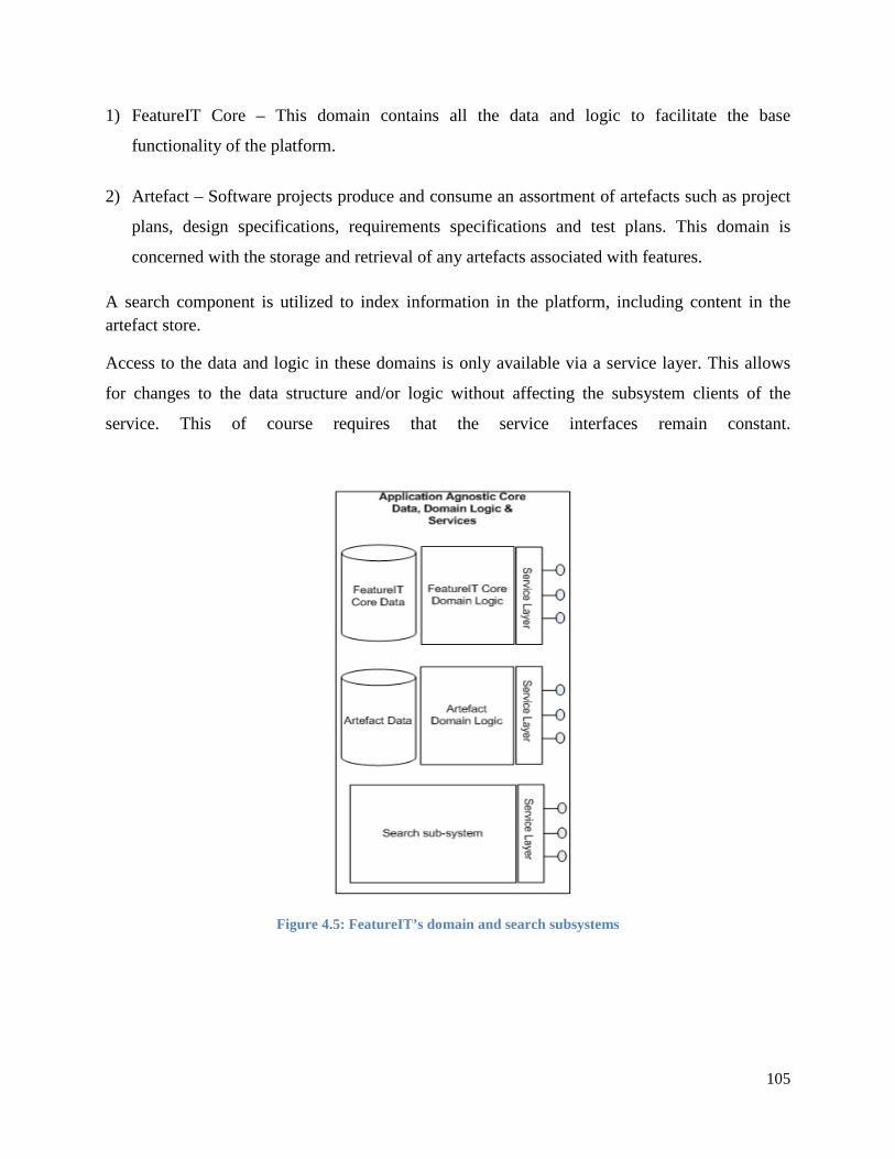
105
1) FeatureIT Core – This domain contains all the data and logic to facilitate the base
functionality of the platform.
2) Artefact – Software projects produce and consume an assortment of artefacts such as project
plans, design specifications, requirements specifications and test plans. This domain is
concerned with the storage and retrieval of any artefacts associated with features.
A search component is utilized to index information in the platform, including content in the artefact store.
Access to the data and logic in these domains is only available via a service layer. This allows
for changes to the data structure and/or logic without affecting the subsystem clients of the
service. This of course requires that the service interfaces remain constant.
Figure 4.5: FeatureIT’s domain and search subsystems

106
4.7.3 Enterprise infrastructure integration layer
Figure 4.6 illustrates the integration layer of the FeatureIT application. In an enterprise there are
several systems already exist and should be utilized if available. These include source control
management (SCM) systems, user registries that hold authentication, authorization and role
information and document stores. I will address each of these in turn:
1) Source control system – FeatureIT does not ship with a source control system. Instead it
assumes that there is already one installed and available in the enterprise. The integration
layer will provide access to link source control meta-data such as change lists and change
comments to a feature.
2) User account repositories – If an enterprise already employs a user directory such as
Lightweight Directory Access Protocol (LDAP) they can utilize this so that a user can use
their existing credentials to access the FeatureIT application. Roles and relationships will be
imported into the social container that will manage these (discussed later).
3) Project document stores – FeatureIT will provide the functionality to import documents that
reside outside of the system so that they can be linked to existing features.
It is important to note that FeatureIT will not synchronize users’ accounts or documents back to
the originating source.
Figure 4.6: FeatureIT integration with legacy systems

107
4.7.4 Applications deployed inside the FeatureIT collaboration platform
There are of two kinds of applications deployed inside the FeatureIT collaboration platform:
1) Native FeatureIT applications that make up the base functionality as outlined in the
functional requirements. These include applications for viewing and updating features,
prioritizing features, etc.
2) Applications that the enterprise have developed to enhance the FeatureIT functionality. These
applications are written in the same language as FeatureIT and deployed into the same
container. An example of a custom application might be a dashboard application to monitor
the states that features are in at a given point in time. There might also be cases where native
FeatureIT applications are insufficient to meet the needs of the organization and are replaced
by custom build applications.
It is important to note that these FeatureIT applications only contain business logic and interface
directly with the domain services. The user interfaces of these applications are developed and
deployed separately into a portal container and communicate with application via services. This
will be discussed in more detail next.
4.7.5 Presentation subsystem (implemented using a web portal)
User interfaces of FeatureIT applications are deployed separately into a web portal and
communicate with the application logic by means of services. The reasons for this are as follows:
1) A clear separation between business logic and presentation logic is made explicit for all
FeatureIT applications.
2) We can increase the scalability of a portal by moving data access and business logic into
separate physical tier. The portal is only responsible for presentation logic.
An existing web portal product is used to house the presentation logic as it provides various
services, by default including authentication and authorization, personalization and the ability to
surface user interfaces from remote applications. Modern portal containers also support the
deployment of mashups which are a key Web 2.0 technology for rapidly assembling new

108
applications. Other Web 2.0 applications including tagging, news feeds (via RSS or Atom), blogs
and wiki’s that come standard with portals will also be used.
4.7.6 External application integration layer
The final important aspect of FeatureIT’s architecture is its ability to surface the presentation
logic of custom built applications inside the same user interface portal as other FeatureIT
applications. This is illustrated in Figure 4.7. The application logic can be written and deployed
onto any platform that allows its presentation logic to be remoted via Web Services Remote
Portlets (WSRP) protocol. If this is not possible, basic user interface integration can be
accomplished via HTML IFrames.
It is possible to write remote application logic in almost any langauge of choice because REST
based application programming interfaces (API’s) are exposed that facilitate access to
FeatureIT’s business logic and data.
Plug-ins for office productivity tools such as word processors, spreadsheet programs, project
planning applications and email clients will also publish information and artefacts into the
FeatureIT platform without having to leave these systems. This will reduce application switching
and create a more satisfying end user experience.

109
Figure 4.7: Consuming remote applications and artefacts from inside FeatureIT
4.7.7 FeatureIT’s social container utilization
FeatureIT makes use of a social container to maintain the user profiles. The user profiles, their
roles and relationships with each other are imported from an existing user store, such as
Lightweight Directory Access Protocol (LDAP), and the information is synchronized with the
social container inside FeatureIT at regular intervals. The social container also manages the
relationships between artefacts stored in the system and the relationships between users and these
artefacts. The social container exposes this profile and relationship information via an API that is
consumed by FeatureIT applications.

110
In this section I have provided the high-level physical architecture of the FeatureIT collaboration
platform. I have also described the various components of the platform and their relationships
with each other.
4.8 Summary of the FeatureIT components
Table 4.1 provides a summary of the components of the FeatureIT collaboration platform describing which of requirements listed in Section 4.3 they satisfy.
Table 4.1: FeatureIT components and the requirements they satisfy
Requirement
Architecture component(s) responsible
Description of how architecture component(s) satisfies requirement
Ease of entering software system requirements into the system
- Feature input/progress notification component - Workflow component - Web portal
The FeatureIT platform has an interface component that allows features to enter the platform using multiple mediums. These include a user interface on the FeatureIT web portal, email, microformat or a web form on an existing application that communicates with the feature input component. The workflow component of the FeatureIT platform allows for the routing of features based on the attached meta-data.
Information inside the platform must be viewable, modifiable and extendable for authorized users
- Platform logic, data domain - Web portal - External application integration layer
The web portal of the FeatureIT platform allows role-based access to information and services. The notion of a “feature” which is a rich data item, that itself can contain one of more other features (to any depth) is implemented in the platform logic of the platform and stored in the FeatureIT data domain. FeatureIT has an artefact store that supports the saving of documents and other resources inside the platform (connected to a “feature”). The external application integration layer interfaces with the existing user repository to import user accounts, user roles and the relationships between users. This user account, and role information is utilized by the web portal to allow role based access.

111
Requirement
Architecture component(s) responsible
Description of how architecture component(s) satisfies requirement
The view of the system state must be determined by user role
- Web portal - External application integration layer - Social container
The external application integration layer interfaces with an enterprise’s existing user repository to import user accounts, user roles and the relationships between users. This user account, role and relationship information is utilized by the web portal to facilitate views most applicable to the logged-in user’s role (personalization). In addition, this information is stored in the social container and used to manage the relationships between people, artefacts and any combination of these.
The information in the platform must be searchable
- Web Portal - Search component
FeatureIT allows for the searching of artefacts and information via two mechanisms:
(1) Traditional indexing of artefacts and the searching of these indexes to locate resources.
(2) The web portal allows for the adding keywords to resources (tagging and the creation of folksonomies) by users.
Both of these mechanisms should be included in the search process. Tagging allows for the formulation of tag clouds which aid in search via recognition rather than recall. Since tags are hyperlinks, they also allow the platform and its information to be navigated.
The collaboration platform must support the entire SDLC and all stakeholders
-Web portal - Platform logic and data - External application programming interface - External application integration layer
Since FeatureIT is first and foremost a collaboration platform, any applications that will aid in the SDLC processes can be developed and plugged into the platform for consumption via the web portal or even applications external to the platform. The platform has a powerful and extensible logic and data domain available via a well-defined service layer. All stakeholders are provided role-based access to

112
Requirement
Architecture component(s) responsible
Description of how architecture component(s) satisfies requirement
the web portal. The external application integration layer interfaces with an enterprise’s existing user repository to import user accounts and user roles.
Users must be aware of the activities taking place within the collaboration platform
- Feature input/progress notification component - Web portal
Users of the FeatureIT platform can subscribe to events they are interested in and have those notifications delivered in the medium of their choice. This is asynchronous awareness of activities that took place by others using the platform. An activity stream (a chronologically ordered list of events that took place) can be surfaced in the web portal for synchronous awareness.
The collaboration style that best suits the user must be supported by the platform
- Feature input/progress notification component - Web portal - External application integration layer
Use of the platform will most likely be through the user interface of the web portal. However, users should be able to publish into and consume from the platform even if they are outside of the platform, using a plug-in that interfaces into FeatureIT via the external application integration layer. There are numerous ways of entering information and receiving notifications via the feature input/progress notification component.
The collaboration platform must be extensible
- Web portal - External application programming interface - Platform logic & data domain
The web portal allows users to construct their own extensions to the platform and the functionality provided using mashup technology. Trained IT personnel can create applications that extend the platform using and/or expanding the platform logic and data domain of FeatureIT. These applications can be deployed inside the platform or can be external to FeatureIT and interface with the platform via the external application programming interface (when developing plug-ins for example).
The collaboration platform must have
External application programming
There might be requirement to publish into or consume data from the FeatureIT platform by

113
Requirement
Architecture component(s) responsible
Description of how architecture component(s) satisfies requirement
open application programming interfaces (API’s)
interface external applications. This is accomplished by applications outside of the platform interfacing with the external application programming interface.
The collaboration platform must co-exist and utilize with existing enterprise infrastructure
External application integration layer
The external application integration layer allows the FeatureIT platform to consume existing information from user registries, artefact stores and source code management systems. This eliminates duplication of resources and easier management for the enterprise infrastructure personnel.
The collaboration platform must have multiple deployment options
The entire platform The nature of the platform is such that it can be deployed as an on-premise solution, utilized as Software as a Service (SaaS) or deployed as a private cloud offering. In the later case, a single division in the enterprise can provision multiple instances of the platform for different divisions within the organization.
4.9 Conclusion
This chapter has provided a description of the problem domain in terms of building a
collaborative platform for the development of enterprise software. Studying the problem domain
allowed me to formulate a number of requirements, functional and non-functional, necessary to
construct an effective collaboration platform. The problem domain was defined in terms of the
difficulties inherent in developing enterprise software and the limitations of current CSCW
systems in the realm of assisting in the process of software development. These requirements
were used to formulate an architecture for a collaboration platform that can assist in the creation
of enterprise software. I presented a high-level physical architecture model and I will, in the next
chapter, supplement this architectural description with scenarios. These scenarios will
demonstrate that the architecture fulfils the requirements identified in Section 4.2.

114
Chapter 5: Validating the high-level architecture
5.1 Introduction
In the previous chapter I presented the high-level architecture for a collaboration platform that
will facilitate the creation of enterprise software. This architecture was the result of identifying
functional and non-functional requirements necessary to move from the problem domain
(described in Section 4.2) to the solution domain.
I documented this architecture using the physical view of the “4+1” view model for systems
architecture (Kruchten, 1995). In this chapter I will present a number of important and typical
scenarios that will describe how the proposed platform will meet the functional and non-
functional requirements identified in Section 4.3.
Scenarios are narratives of people and the activities they perform in a specific context (Carroll,
1999). It has become commonplace to utilize scenarios to evaluate various design alternatives to
come up with the final design that best satisfies the requirements (Kazman, Abowd, Bass, &
Clements, 1996).
The scenarios presented in this chapter will be used to illustrate how the architecture of the
FeatureIT collaboration platform assists all the stakeholders in the Software Development Life
Cycle (SDLC) to construct enterprise software. In addition, the scenarios will allow for
traceability between the requirements identified and the architecture proposed to realize those
requirements.
5.2 Scenarios validating the FeatureIT architecture
In this section I will present scenarios that span the entire SDLC at a fictional organization to
illustrate how the FeatureIT collaboration platform assists in the process of creating and
maintaining enterprise software. I will begin by providing the context, that is, a brief description
of the fictional organization, and the stakeholders involved in the process of software
development. I will also present several scenarios related to the introduction of FeatureIT into
the organization that demonstrates how the platform attempts to utilize as many enterprise assets
as possible, thereby reducing duplication.

115
5.2.1 Impetus (the fictitious organization)
Impetus Financial Services (from now referred to as “Impetus”) is one of the largest insurance
companies in South Africa which primarily serves the upper income market. This is
accomplished by providing financial advice and selling a wide range of financial products (either
directly or through intermediaries). These products include life insurance, investments, medical
aid and short-term insurance. Impetus is divided into several distinct divisions for product
development, sales, external distribution and service. The sales division is responsible for
distributing products and offering financial advice to customers. The Impetus sales division has
the long-term strategy to reduce costs and increase revenue by effectively utilizing technology.
The sales division has as a large Information Technology (IT) team that has aligned itself closely
with business in order to deliver software solutions that contribute to the bottom line.
5.2.2 The current operating model of the Sales IT division
Although the sales IT team is quite successful at delivering software systems that meet business
expectations there is also room for improvement. The team, which is now five years old, has
been growing in size and has an increasing number of systems in production. There is therefore a
combination of new system development, the enhancing and maintaining of existing software to
meet new and changing business requirements as well as day-to-day operational issues.
When new systems need to be constructed or major system enhancements need to be performed,
the process begins with a series of meetings and workshops. Much value (and documentation
artefacts) relating the problem is gained from these sessions. There is however no “trigger” to
indicate that the project has officially started (and to notify interested stakeholders) and that
progress has been made. The first discernible notification of progress to (hopefully all)
stakeholders is usually a manually drafted email with links to documentation stored on whatever
store is preferred by the person communicating to stakeholders (or worse, the documentation is
attached to the email).
There are a number of tools used and activities performed within the SDLC of this division:

116
1) Specifications, project plans and other documentation is stored on a file system, the team
wiki or inside a Computer Assisted Software Engineering (CASE) tool, depending on the
preference of the party creating the artefact.
2) Defects discovered in existing and new projects are recorded on a web-based incident
management system.
3) System operational tasks such as logging system change requests and deployments are done
on a web-based task management system owned by the operations team.
4) Communication with stakeholders with regard to progress is via electronic mail. This is
either on request or ad hoc basis.
5) Requests for minor enhancements to existing systems or operational change requests happen
via electronic mail or word of mouth. These requests are managed by spreadsheet.
6) A physical whiteboard displays the progress of a project and what each member of the team
is currently occupied with.
7) A source control system is used to store and version source code for the various software
systems.
These tools can be considered collaborative in nature since they convey information between two
or more parties. These tools either communicate information (for example, a project status email)
or act as a signal to begin work (for example, a defect logged). Tools such as integrated
development environments (IDE’s) that are used within the SDLC, but do not foster
communication between individuals are excluded from further discussion.
There are a number of problems with the way in which the sales IT team operates in their
collaboration efforts as facilitated by their current toolset:
1) Project documentation is stored in multiple locations and the existence of the documents (or
updates to documents) is communicated via electronic mail on an ad hoc basis.

117
2) There is no convenient way for stakeholders to view the status of a new project or project
enhancement.
3) There are multiple systems, not integrated and requiring different authentication and
authorization credentials, where collaboration efforts such as document viewing, defect
tracking and operations management are performed. With so many distinct systems, the IT
division is considering hiring an administrator to oversee these systems. This is an
unnecessary cost that could be eliminated by system consolidation.
4) Although the source control system allows fellow developers to see the changes that each
source code commit entailed, there is no way to tie the source code changes to defects or new
software development efforts.
5) There is no single place where ad hoc electronic communication is kept and this
communication cannot be tied back to a development task or defect resolution.
6) The introduction of any new tools to assist in any aspect of SDLC would most likely result in
yet another disparate system that users need to log into and the operations team needs to
maintain.
Because of these problems, the sales division at Impetus has decided to implement the FeatureIT
collaboration platform that they are confident will assist in the development of their enterprise
software systems.
5.2.3 Scenarios that illustrate how FeatureIT is introduced into the enterprise from an infrastructure perspective
Impetus has been in existence for a number of years and therefore has a number of existing IT
infrastructure assets. IT governance at Impetus requires that any new platform introduced must
make use of these existing assets. The ease of implementing and operating a new platform is also
of paramount importance.

118
5.2.3.1 Integration with the existing user registry
Impetus has an existing user registry that houses all the user accounts of its employees and
partners (such as financial planners). This registry also holds the roles of the users and their
relationships (who reports to whom).
FeatureIT uses the underlying security component of the application server onto which it is
deployed to allow automatically for authentication and authorization. There is also an import
process that extracts users, their roles and their relationships into the social container
(responsible for maintaining party and artefact relationships) employed by FeatureIT. All
changes to the information inside the user registry are synchronized with the social container
every night. No user account information can be changed from the FeatureIT interface.
5.2.3.2 Integration with the existing source control management system
Impetus uses the Subversion (SVN) source control management system
(http://subversion.apache.org) to store and version their source code. FeatureIT uses the SVNKit
(http://svnkit.com) product that allows it to interface seamlessly with their SVN installation.
Developers at Impetus can therefore attach SVN code revision numbers to features inside the
platform for traceability between these features and the corresponding source code that realized
them.
5.2.3.3 Integration with the existing document stores
Any document repositories at Impetus that support the Content Management Interoperability
Services (CMIS) standard (https://www.oasis-open.org/committees/cmis/) can have their content
imported into FeatureIT. One of the most important content stores at Impetus is Microsoft
SharePoint (http://sharepoint.microsoft.com ), which supports the CMIS standard. It is therefore
possible to import all relevant existing documents from SharePoint into FeatureIT where they
will be stored and versioned going forward.

119
5.2.3.4 Deployment and operation of FeatureIT
FeatureIT will be deployed on a Java Enterprise Edition (JEE)
(http:// www.oracle.com/technetwork/java/javaee/index.html) application server infrastructure.
Impetus, like many modern enterprises, has a JEE environment and is adept at commissioning
and operating applications on this platform.
Since they have the necessary skills, Impetus has opted for an on-premise installation of
FeatureIT. For enterprises without JEE skills or infrastructure, FeatureIT can be utilized by
means of the software as a service on the cloud.
The success of FeatureIT within the sales division could result in a private cloud deployment,
where the multiple instances of the platform are managed from a single installation for the other
divisions at Impetus.
5.2.4 Scenarios that illustrate the use of FeatureIT at Impetus during the SDLC
FeatureIT addresses the problems in the SDLC identified in Section 5.2.2, by providing a
platform to assist in communication and coordination between all stakeholders in the
development and maintenance of enterprise software. The result of this collaboration platform is
a coherent view of the entire SDLC across multiple projects in the enterprise.
The scenarios that will be presented in this section illustrate how the process of creating and
maintaining enterprise software is improved after the introduction of FeatureIT into the Sales IT
team. These improvements are due to the collaborative nature of the system, which takes all
stakeholders into account, the ability to attach all related artefacts to features and the capability
of the platform to be extended and enhanced to fit the organization’s requirements now and in
the future.
Table 5.1 lists the roles and responsibilities of the Sales IT team and their business stakeholders.
The stakeholder responsibilities were previously defined in Table 2.1. They are repeated here for
convenience. The names of these stakeholders have also been provided so I can refer to the
individuals by name in the subsequent scenarios.

120
Table 5.1: Roles and responsibilities in the Sales IT team
Stakeholder/Role Person(s) in Sales IT
Responsibility
Business owner Johan (Chief executive officer)
Johan has business-driven technology requirements within the Sales division at Impetus and ensures that the software developed is in line with business strategies.
End user Peter (Financial planner)
Peter is one of the many end users that utilize the delivered technology solutions in his day-to-day work as a financial planner in the Sales division. Peter is an enthusiastic user who submits many requests for enhancements and offers his time to test new functionality and systems before they are delivered to the rest of the end user population.
Business analysts Rensche Marle
These two individuals are the bridge between business and information technology (IT). They need to understand the business problems and requirements and translate them into intelligible descriptions of the problem space for system analysts.
System analyst Amanda Amanda takes the business requirements, as discovered and documented by the business analysts, and analyses them in terms of the impact they will have on existing systems and processes. She also identifies whether there are existing software assets that can be reused or modified to fulfil the business requirements.
System architect Gawie Gawie has a coherent view of all the relevant systems and their interconnections inside the Sales division and across all business units at Impetus. He is also responsible for laying down standards in terms of platform technologies. In addition, Gawie discovers and documents the high-level components (and their interconnections) that will make up any new software solution. A solution could conceivably result in necessary changes to platform or design decisions. These changes must be assessed and decisions communicated to system analysts and developers.
Project manager Yvonne Yvonne is responsible for coordinating the various

121
Stakeholder/Role Person(s) in Sales IT
Responsibility
projects that Sales needs to develop. Since IT resources are scarce and expensive, the optimal delivery of projects needs to be managed. Unforeseen complications in one project could impact several running or future projects and this needs to be communicated to business stakeholders.
Software developers
Franco, Warren, Sharon
These individuals are responsible for creating the software artefacts that will result in a business solution. Typically several developers work concurrently on one or more projects in the Sales division. They constantly need to communicate with each other during their work and with other parties such as business analysts (to clarify requirements) and project managers (to communicate progress), for example.
Technical lead Hank The efforts of the various developers need to be coordinated at a technical level. Design patterns, coding standards and architectural vision needs to be adhered to and enforced by Hank. Hank also spends a significant amount of effort liaising between the architect and infrastructure personnel to ensure that various technical issues (such as possible changes to architecture and deployments of code artefacts to appropriate environments) are addressed. This frees the developers to concentrate on producing quality code that meets the business requirements.
Testers/Quality assurer
Yashika Yashika has the responsibility of ensuring that the system meets its objectives in terms of functional (was the right solution built?) and non-functional (does the system perform well? Is the system secure and stable?) requirements. Communication between Yashika and developers is commonplace as errors are reported to the developers for resolution. Yashika also need to ensure that she is clear on what the system needs to accomplish so that her testing is effective. This requires constant liaising with business analysts.

122
Stakeholder/Role Person(s) in Sales IT
Responsibility
Infrastructure personnel
Casper Delivered software solutions needs to be moved from one environment to another as the project progresses. The technical lead or developers need to make sure that infrastructure (such as application servers) are commissioned and correctly configured. These are the responsibilities of Casper.
Operations personnel
Andrew Once an application is in a production environment, operations personnel, such as Andrew, are responsible for the day-to-day monitoring of the application in terms of system incidents and performance. Should problems be encountered in production, he would need to liaise with the development team and technical lead to resolve issues as early as possible before they impact business.
Process owner
Vikash Vikash is responsible for the day-to-day operations of the delivered applications from a business perspective. When a new application is delivered, Vikash also acts as a change agent ensuring that business processes assimilate the new software and that end users are familiar with the operation of the delivered solution. Vikash also engages with end users to resolve any business-related issues that might emerge post-deployment and is a wealth of knowledge with regards to how a production system can be changed to streamline the existing business processes.
All the scenarios below revolve around the following situation in the Sales division of Impetus.
Johan, the CEO of the Sales division at Impetus, has realized that it is too expensive to outsource
the monthly commission payments of the financial planners through their existing partner. He
believes that if the commission system is built and maintained by his current IT team not only
will it be more cost effective, but he can also add competitive advantage features (such as ad hoc
payments) to the system. This is not a trivial project and will require the entire IT team during
the various phases of the SDLC.

123
5.2.4.1 Requirement for a new project entered into FeatureIT
Johan logs into the FeatureIT web console and enters his business requirement for a new, in-
house built, commission system in as much detail as possible. There are several feature types in
FeatureIT including:
• New system (business feature)
• Minor enhancement to an existing system (business feature)
• Major enhancement to an existing system (business feature)
• Defect repair to existing system (business and technical feature)
• Operational issue with new or existing system (technical feature)
He selects “New system” as the feature type. This is an extensive business feature that will
require many sub-features (such as analysis, design, implementation, testing and
commissioning), some business, others technical in order to be realized.
He adds himself as a business subscriber to this feature so that all business-related (as opposed to
technical-related) changes to this feature will result in him receiving email notifications.
5.2.4.2 Analysis begins on the feature request
During the installation of FeatureIT, the workflow for a new system feature was configured so
that an event is triggered notifying the business analysts (Rensche and Marle) when a new
system is requested. New system requests are not as frequent as other kinds of features (such as
minor system enhancement requests) and are handled with much rigour. Marle and Rensche
liaise with Johan verbally through meetings and the result is many artefacts (such as meeting
minutes and any other documentation drafted) of importance to the project. The business analysts
log onto the FeatureIT platform and create sub-features for the business analysis tasks they are
engaged in. To these sub-features, they attach the artefacts that resulted from their verbal
interactions with Johan. These artefacts are tagged with keywords to aid in searching and
organization of the artefacts.

124
5.2.4.3 Deciding on whether the feature is worthy of realization
The results of the early analysis phase show that building the commission system is feasible and
can result in significant cost savings for the sales division at Impetus. There are however many
other projects scheduled that have also been deemed worthy of constructing. To decide whether
the project should receive priority, a number of people are asked to vote on the feature. These
individuals are members of the Sales Executive Committee (Exco). They are sent a voting
invitation by Johan through the FeatureIT system that results in an email to each voter that
contains a link to the feature description with access to all the supporting artefacts gathered in the
early analysis phase.
Their voting options are as follows:
• Vote feature up – High priority
• Vote feature up – Medium priority
• Vote feature up – Low priority
• Vote feature down (feature not worthy of realizing).
Johan can assign weights not only to the vote (the priority) but also to the people voting. Exco
members who best understand finance (such as the Chief Operating Officer) have higher weights
assigned to their votes than those who do not (Head of Human Resources, for example). Voters
can add motivations to their votes to justify their positions.
The exco members receive their email invitations and dutifully vote on the new commission
system proposed after reading Johan’s motivations and the relevant documentation assembled by
the business analysts, Marle and Rensche. The results of the voting process show an
overwhelming support for the new commission system initiative. So much so that it is decided
that work on the commission system is to begin immediately. The resulting votes and the overall
result are attached to the feature for later justification.
Voters are free to subscribe to the “create a commission system” feature so that they can be
notified of changes to the feature (and subsequent sub-features) either via email or the newer
web-based syndication mechanism (RSS or Atom).

125
5.2.4.4 Intensive business analysis to realize the feature begins
The business analysts (Rensche and Marle) work with Johan and other subject matter experts to
better understand the requirements for the new commission system. The various analysis
activities are sub-features attached to the main feature (build a commission system). The creation
of these sub-features is via the FeatureIT web interface. All information gathered during the
business analysis phase are either directly added to the sub-feature in the form of a WYSIWIG
editor or by attaching documentation artefacts. All attached documentation is described and
tagged to ease searching for artefacts.
The description of the current commission system is documented in a word processor document.
This document is attached to the ”Analyze the current commission system” sub-feature and
tagged with the keywords ”analysis document”, ”commission system” and “legacy commission
system analysis”.
FeatureIT plug-ins for the word processor means that uploads of artefacts can be done from
within the word processor without having to log onto FeatureIT.
The refined functional requirements for the new commission system, as a result of the analysis
performed by Rensche and Marle, are entered by the business analysts into the “Functional
requirements” sub-feature using the FeatureIT WYSIWYG editor. This sub-feature is tagged
with the keywords “commission system” and “functional requirements”.
Since Johan has subscribed to any business changes to his feature, he will be notified via email
whenever the feature or these sub-features are updated. He will therefore be aware of the
progress made to his feature request. Johan is free to add comments or ask questions which in
turn will notify the person who updated the feature that someone has commented on their feature
update.
Rensche and Marle can collaborate during their business analysis activities by commenting on
details of the sub-features that the other person is working on. They can do this verbally, via
email or instant messaging. In the case of verbal or instant messaging communication, discipline
is required of Rensche and Marle to either summarize, or cut-and-paste any important
collaboration discussions and attach these to the feature for others to view. This is not the case

126
for email communication, since there is a plug-in for their email application which allows emails
to be imported into FeatureIT, and attached to the appropriate feature. Marle and Rensche make
a note that they would like the sales IT team to develop a similar plug-in for their instant
messaging client.
All the sub-features created by Marle and Rensche are assigned the right altitude (business
focused) in order to provide the most relevant default information to the users logging into
FeatureIT.
5.2.4.5 Systems analysis to realize the feature begins
At some point during the business analysis phase it is decided that system analysis should
commence. Amanda, the systems analyst, subscribes to the “Create a commission system”
feature so she can understand the information gathered by the business analysts, and can ask
relevant questions to assess the impact of the new commission system on existing systems. She
suggests that the architect, Gawie, also subscribes to the feature and sends him an invitation to
follow the feature from the FeatureIT web console.
Gawie and Amanda use face-to-face meetings, email and instant messaging to communicate with
each other and the business analysts, Marle and Rensche, to marry the business requirements
with the high-level architecture of the system that will become the new commission software
product. New sub-features relating the system analysis and software architecture activities are
created as appropriate. All artefacts and other communication are attached to the appropriate sub-
features.
The sub-features created by Amanda and Gawie are assigned the right altitude (technically
focused) in order to provide the most relevant default information to the users logging into
FeatureIT.
As always, interested subscribers are notified via their preferred mechanism (email or web-based
syndication) as sub-features are created and enriched with artefacts and other information.

127
5.2.4.6 Systems architecture of the new system is defined and documented
Gawie, because of his interactions with the business analysts and systems analyst, has a thorough
understanding of what needs to be built and how the new system will impact existing systems.
He can therefore start formalizing the architecture necessary to begin the detailed design of the
new commission system. Gawie creates an architecture sub-feature to attach all his artefacts and
allow others to comment on his work and be notified of progress. These sub-features are
assigned the correct, technically-focused altitude.
During the architecting process he clarifies information with the business and systems analysts
thereby enriching his and their sub-features in the process as existing issues are better understood
or new, previously overlooked issues, are identified.
Near the completion of the architecture activities, Gawie invites Hank, the technical lead to
follow the “Create commission system” feature. Gawie believes that Hank now needs to become
familiar with the business requirements and architecture so he can begin designing lower-level
components and prepare the development team for the upcoming programming activities.
5.2.4.7 The new commission system is designed
Hank, in collaboration with Gawie, conceives a high-level design to satisfy the requirements of
the new commission system. These designs are manifested as diagrams and documents attached
to the design sub-feature created by Hank. During the design process several requirements need
clarification from the business and systems analysts. These clarifications are elicited by posting
questions on the appropriate business related sub-features. The business and systems analysts
are notified by email that their sub-features have been updated and log into FeatureIT to answer
the questions posed by Hank. Hank, in turn, receives email notification that his questions have
been answered.
With the design in place, Hank believes it is time to invite the developers to follow his design
sub-feature so they can become familiar with what needs to be built.
Gawie and Hank decide it would be best to subscribe to the business level sub-features so they
can track any changes that happen from a business perspective.

128
5.2.4.8 Development of the new commission system commences
The developers, Franco, Warren and Sharon, receive their invitations to follow the design sub-
feature of the new commission system via email. All three developers join the sub-feature and
begin to study the design for the new commission system. They find that they also need to study
the architecture and business level sub-features so they can get an overall view of the project.
Like Gawie and Hank, the developers decide to subscribe to all the sub-features of the
commission system feature and will therefore be notified when any of these sub-features are
updated.
Each of the developers has several queries related to the requirements, the architecture and the
design of the system. These are addressed as follows:
• Face-to-face meetings are held between all the relevant parties and any clarifications or
modifications are added to the appropriate feature by the developers, notifying all subscribers
of the change so they can confirm they are satisfied with the result.
• Comments or questions can be attached to the relevant feature which will notify all
subscribers of the sub-feature of the update via email. Any subscriber with the necessary
knowledge is free to address the comment or answer the question.
The developers create as many sub-features as necessary to create the executable code that will
satisfy the requirements for the new commission system while adhering to the design and
architecture of the system.
In addition, the developers provide time estimates for completing their features. This allows the
project manager, Yvonne, to have a view on time to completion. Yvonne subscribes to the
development sub-features and keeps track of the estimated versus actual times for the
development of features.
The developers have decided that it will be beneficial to add the names of the files, and their
revision numbers, of the code they check into the source code system against the sub-features
they create to allow for traceability between the development sub-feature and the source code
that realizes that feature.

129
Franco realizes that it would be beneficial if there was an extension to his integrated
development environment (IDE) that would ease the process of correlating his code changes
against one or more sub-features that the code is related to. He plans on writing such an
extension once this project is complete.
Since the implementation of features has begun, the project manager Yvonne urges the tester,
Yashika, to subscribe to the development features.
5.2.4.9 Testing the development efforts of the commission system
Yashika, is notified of changes to the development features she has subscribed to. When the
developers have noted that these features are complete and ready for testing, she dutifully tests
the functionality against the specifications drawn up by the business analysts, Marle and
Rensche. She logs onto the FeatureIT platform and searches for these specifications. Any defects
found by Yashika, are logged against the feature and the appropriate developer is notified.
Yashika, sees there is a problem with the totals of the new commission reports and logs this
against that feature. Since Franco is the owner of that feature, he is notified of this defect. He
looks at Yashika’s comments and fixes the problem. He updates the feature which notifies
Yashika that it is ready for testing. Yashika retests and the problem it is indeed resolved. Yashika
closes the defect and Franco is notified of this.
5.2.4.10 Implementing the production infrastructure for the new commission system
Once all the development and testing of the new commission system is complete, Hank, as
technical lead is required to ensure that the system is deployed to production. This involves
implementing the production infrastructure that the new commission system will be deployed to.
He knows that Casper is the dedicated person responsible for this task and creates a feature for
deployment (assigning it to the correct altitude, technically-focused).
Casper receives the notification of the feature and he and Hank communicate by updating the
feature and creating new sub-features as necessary until the new infrastructure is implemented
and the new commission system is deployed and available to end users.

130
5.2.4.11 Repairing a defect on the commission system
Vikash, who is responsible for the day-to-day operations of the commission system receives a
call from Peter, a financial planner, who complains that all the transactions display on his
commission report except for the health business he sold. Vikash creates a new feature for this
defect and assigns a developer, Sharon to the feature.
Sharon receives this notification and investigates the problem. Once she has repaired the defect,
she assigns Yashika to the feature so it can be tested. Yashika receives the notification and finds
that the problem has been resolved. Vikash, the creator of the feature has been informed of
progress at all times by FeatureIT and he calls Peter to tell him the problem will be deployed to
production that evening.
He also tells Peter that he is welcome to log any requests for defect repairs or enhancements
directly from inside the commission system, where a feature request web form is available.
Vikash explains to Peter that he will always be notified of progress should he desire. These
requests enter the FeatureIT platform via the API layer.
5.2.4.12 Making an operational change to the commission system
The defect repaired in Section 5.2.3.11 requires a deployment of code into production. Andrew is
the operations person responsible for this. Sharon creates a “deploy code to production” sub-
feature to the defect feature and assigns this to Andrew.
Andrew receives the notification and deploys the code change that evening using the instructions
provided by Sharon. Vikash, Sharon and Yashika are all informed that the code is deployed in
production when Andrew updates the feature with this fact.
5.2.4.13 Implementing an enhancement to the commission system
Peter, the financial planner, remembers what Vikash told him about being able to report an
incident or request an enhancement directly from the new commission system. Peter would like
to see the VAT amount of every commission item.

131
Peters enters his request into the commission system and says he would like to be notified when
work begins on the feature and when the feature is complete via email. Marle, the business
analyst assigned to any enhancements for the system, receives Peter’s request. She discusses the
requirement with Amanda (the system analyst) and Gawie (the system architect) and they believe
there will be no significant impact on the existing system. As such, Marle assigns this feature to
a developer, Warren, who is notified of the request. Warren begins work on the feature and Peter
is automatically notified of this via an email sent by FeatureIT.
Yashika, the tester, sees that work on this feature has begun and proactively subscribes to the
feature so she can test it once development has been completed. Yashika receives notification
when the feature is complete and tests that everything works as required.
Sharon assigns Andrew to the “deploy code to production” sub-feature when Yashika is satisfied
that enhancement passes quality assurance. Andrew receives the notification via FeatureIT and
deploys the code for the enhancement to production. Sharon, Yashika, Marle and Peter are
notified once Andrew has completed his work.
5.2.5 Scenarios that illustrate the extensible nature of FeatureIT
Impetus would like the FeatureIT collaboration platform to be extensible so that they do not
require the commissioning of any other systems in the realm of software development. In this
section I provide scenarios that illustrate how end users and more technical personnel can extend
the platform to meet new requirements.
5.2.5.1 End user extensibility of FeatureIT
There is a new requirement at Impetus for Vikash, the process owner, to create a report for
Yvonne, the project manager, showing the number of defects reported during a month and how
much time was spent repairing these defects. This report would also be useful for other members
of the sales IT team.
Vikash is somewhat familiar with mashup technology and is aware that the various FeatureIT
components publish information that can be consumed by a new mashup. Since FeatureIT is
built on top of web portal product (such as Liferay [http://www.liferay.com]) that supports

132
mashups he decides to execute Yvonne’s request by constructing a mashup for the benefit of all
FeatureIT users.
Viskash consumes data on all features of the type “defect repair” and combines this with the
“actual time taken” data per item. He applies a time constraint of the last 30 days to data he lays
out on the web report.
Using the mashup capability provided by the FeatureIT platform (by virtue of the fact that
FeatureIT utilizes a web portal), Vikash has created new functionality that is available to all
users of the platform. This was accomplished without the need for a development resource.
5.2.5.2 Software developer extensibility of FeatureIT
I mention in Section 5.2.4.4 that the business analysts, Marle and Rensche, use their instant
messaging client to communicate with each other while they perform their analysis activities.
Much useful information is discussed during their messaging and they find it tedious to have to
cut-and-paste this into the relevant feature.
They ask Warren, a developer, if he knows whether these interactions can be imported into
FeatureIT, as they can do with their word processor. Warren knows he can add a plug-in to their
instant messaging platform and he is aware of the open API available to interact with the
FeatureIT platform. He agrees to assist Marle and Rensche and after a short time he develops a
plug-in for their instant messaging client that allows them to select sections of their chat, right
click on the selection, and select the “import into FeatureIT” option. This option displays a
dialogue box which allows them to add the selected text into the appropriate feature within the
FeatureIT platform. The need to switch between two disparate applications has been eliminated.
5.3 Conclusion
In this chapter I have presented a number of scenarios that illustrate the manner in which
FeatureIT fulfils the requirements identified for a collaboration platform that aids in the
development of enterprise software across the entire SDLC. These requirements encompassed
the functional and non-functional requirements that were described in Section 4.2.

133
The scenarios, and the role that FeatureIT plays in these scenarios, demonstrate that the entire
SDLC and all the relevant stakeholders are supported. In addition, I illustrated how the FeatureIT
platform can be introduced into an organization making use of existing enterprise assets. Finally,
I presented scenarios that show the extensibility of the platform to meet the changing needs of
the organization.
In the next chapter I will present the conclusion of this dissertation that summarizes what this
research study has accomplished.

134
Chapter 6: Research study conclusion
6.1 Summary
This dissertation has explained why collaboration within the enterprise is important for achieving
strategic and operational objectives. My particular focus has been on the importance of
collaboration for the creation of enterprise software. Software development is inherently a
collaborative activity that requires a large amount of communication and coordination between
stakeholders in order to achieve a successful outcome (Lee & Shiva, 2009).
To support in the production of software, early research in the multidisciplinary field of
Computer Supported Cooperative Work (CSCW) gave rise to CASE tools. These tools met with
limited success for a number of reasons (Saeki, 1995). The increase in size and complexity of
software coupled with the distributed nature of software development, partly due to economic
factors, has fuelled the need to find ways to facilitate collaboration in the arena of software
development.
At the same time the paradigm and enabling technologies of Web 2.0 and Enterprise 2.0 have
emerged as possible solutions that can aid in the collaboration required to construct successful
software systems.
The research questions investigated in this dissertation were:
1. What are the functional and non-functional requirements for an architecture to support the
collaboration requirements throughout the complete SDLC?
2. What should an architecture for the construction of a collaboration platform to assist the
production of enterprise software (and that fulfil the requirements identified in 1 above) look
like?
To this end, I presented a high-level physical architecture (Kruchten, 1995) for a collaboration
platform that I have titled FeatureIT (research question 2). The goal of this platform is to assist in
the delivery of enterprise software across the entire SDLC taking all the diverse stakeholders and
their requirements into consideration. This architecture embraces the lessons learned from the
field of CSCW and marries those with the paradigm and associated technology enablers of Web
2.0.

135
To reach the final architecture presented in this dissertation, I adopted the design science
research paradigm that emphasizes the iterative creation of an artefact (Hevner, March, Park, &
Ram, 2004). Each successive iteration of my attempt to produce an optimal architecture,
concluded with an evaluation activity where the candidate architecture was evaluated against
functional and non-functional requirements I identified by studying the literature and scenarios
typical during the entire SDLC, thus addressing research question 1.
The final result is a collaboration platform architecture that is open and extensible in terms of
technology and processes that will adapt to the organization’s structure and requirements over
time.
6.2 Contribution
Earlier in this dissertation (Section 2.4.5) I discussed several reasons why traditional CSCW
systems have faced poor adoption in organizations. Many of the issues faced when constructing
and delivering a CSCW system exist because these systems are adaptive and socio-technical in
nature. For this reason, not just the system and its operating environment need to be considered,
but also the way these two interact with each other. In this section I will explain how FeatureIT
addresses these issues to ensure end user satisfaction and by consequence wide scale adoption.
Issue:
The system does not satisfy the end users’ expectations, functionally and/or non-functionally
because no one individual or group is aware of all the requirements for all the groups that must
eventually use the system (Grudin, 1988).
How the issue is addressed:
FeatureIT is a collaboration platform with a few generic functions and applications that have
been identified to assist in the software development process. The premise behind constructing
this platform utilizing the Web 2.0 paradigm and associated technologies is to allow the system
to be expanded and customized driven by end user requirements. Web 2.0 technologies such as
mashup’s allow end users to create their own applications that will fulfil their requirements
without any programming knowledge. As more applications, services and data reside within the

136
platform, the more possibilities exist to create applications that were not envisioned when the
system was initially commissioned. In addition, the simple act of users adding data to the system,
through tagging content for example, enriches the system and incrementally creates increased
value for all users of the system.
Issue:
The system does not implement a coherent and effective user interface. Users need to switch
between multiple disjoint applications to perform their work (Reinhard, Schweitzer, & Volksen,
1994).
How the issue is addressed:
Since FeatureIT is built upon a web portal, all applications within the FeatureIT platform will be
surfaced within a single user interface, the web browser. It is possible to render more typical
desktop applications within a web browser such as spreadsheet applications, word processors and
electronic mail clients, thereby lowering the requirement to switch between disjoint applications.
In the case where these types of applications are not rendered inside the browser, plug-ins should
be provided for these applications that allow the user to publish into and consume from the
FeatureIT collaboration platform.
Portal technology also allows a high degree of user-controlled customization in terms of how the
user interface is displayed. New applications that are identified and fall within the intent of
FeatureIT can have their user interface rendered inside the FeatureIT portal, whether or not the
application logic is deployed inside the FeatureIT platform itself.
Issue:
The parties that must use the system do not gain much or any benefit. The benefit is for those
who have commissioned the system (Grudin, 1988).
How the issue is addressed:
The Web 2.0 paradigm and enabling technologies allow control to shift to the end user once the
system has been delivered. End users can decide how they want to the system to look and behave
and can extend the system programmatically (by commissioning small applications that are

137
surfaced within FeatureIT) or by assembling new applications by combining two or more
existing applications (using mashup technologies). It is however, up to the end user to decide
whether to embrace what has been delivered or let the system atrophy.
What should be clear from the foregoing is that the Web 2.0 paradigm and its enabling
technologies, upon which FeatureIT is based, allow for a system that can adapt to the
environment into which it is delivered. However, effective change control resulting in an
environment where users desire the system to evolve so as to better serve its community is vital
for success. This kind of commitment cannot be achieved by any technology alone.
6.3 Reflections on the study
While I believe that the FeatureIT collaboration platform, as proposed in this study, can add
value to the process of developing enterprise software, there is one particular area that has
emerged and strengthened during the time I have being conducting this study that I would have
liked to explore further. This area in information technology is termed Application Lifecycle
Management (ALM).
ALM is a set of activities that spans the entire SDLC and attempts to satisfy the interests of all
stakeholders (Hüttermann, 2011). ALM acknowledges that delivering enterprise software is more
than writing code. It is about the governance of projects, software development and the
operations necessary to support the delivered system.
ALM, although inherently a socio-technical set of activities, does not consider the social aspects
of the organization in which it is employed.
Despite that ALM has similar goals to that of the FeatureIT platform, it suffers from many
shortcomings including:
1) A lack of extensibility of the system by its less technical end users (if at all).
2) An inability of ALM systems to utilize important existing enterprise infrastructure such as
user account stores, thereby reducing redundancy of assets to be managed and improving the
assimilation of the system into the enterprise’s eco-system.

138
3) The failure of these systems to adapt to the organization into which they are deployed and the
inevitable changes that the organization will endure over time.
4) Poor personalization (See Section 2.5.1.3) of user interface based on the role of the
stakeholder using the system.
I contend that these ALM system deficiencies are a result of a poor theoretical foundation with
regards to what has been learned in the multi-disciplinary field of CSCW. A survey of the
literature has confirmed this.
This is not to say that ALM systems are not important. A more thorough study of ALM may
have provided insights that may have strengthened the FeatureIT platform.
Future studies that marry CSCW, Web 2.0 and ALM in the application of supporting the entire
SDLC could be beneficial.
6.4 Future directions
What has been presented in this dissertation is a high-level physical architecture for the
FeatureIT collaboration platform. In order for this platform to be constructed, it is necessary to
define the remaining three views (logical, development, process) of the “4+1” view model for
systems architecture (Kruchten, 1995).
The physical instantiation of FeatureIT will allow for positivistic studies to quantitatively
demonstrate the value and shortcomings of the proposed platform during the process of
developing enterprise software.
I also believe that the proposed solution can be applied to fields other than software construction
in the enterprise. It would be beneficial to apply this study to other work contexts that require a
significant amount of communication and coordination to achieve a successful outcome.
6.5 Conclusion
I hope that the proposed architecture presented in this dissertation will facilitate a physical
implementation that can be studied further using positivistic research techniques to assess
whether such a platform will add quantifiable value in the construction of enterprise software. I

139
am confident that the open and extensible nature of the FeatureIT will allow the platform to be
applied to other work contexts that are heavily reliant on communication and coordination, other
than that of software engineering. Such a study could also prove valuable to increase the
applicability of FeatureIT.

140
References
2000, I. 1. (2000). Recommended practice for architectural description of software-intensive systems. IEEE Std 1471-2000. Retrieved 09 11, 2010, from IEEE Computer Society: http://standards.ieee.org/reading/ieee/std_public/description/se/1471-2000_desc.html
Alag, S. (2008). Collective Intelligence in Action. Greenwich: Manning Publications.
Amrhein, D., & Quint, S. (2009, August 08). Cloud computing for the enterprise: Part 1: Capturing the cloud. Retrieved 02 05, 2011, from IBM Developerworks: http://www.ibm.com/developerworks/websphere/techjournal/0904_amrhein/0904_amrhein.html
Anderson, P. (2007). Technology and Standards Watch. JISC.
Arora, R., & Goel, S. (2012). Collaboration in Software Development: A Spotlight. CUBE’12 , 391-396.
Balthazard, P., Potter, R., & Warren, J. (2004). Expertise, Extraversion and Group Interaction Styles as Performance Indicators in Virtual Teams. The DATA BASE for Advances in Information Systems , 35 (1).
Bass, L., Clements, P., & Kazman, R. (2013). Software Architecture in Practice. Westford, MA: Pearson Education.
Benefield, R. (2009). Agile Deployment: Lean Service Management and Deployment Strategies for the SaaS Enterprise. System Sciences (pp. 1-5). IEEE.
Bentley, R., Horstmann, T., & Trevor, J. (1997). The World Wide Web as enabling technology for CSCW: The case of BSCW. COMPUTER SUPPORTED COOPERATIVE WORK , 111-134.
Bernal, J. (2009). Web 2.0 and Social Networking for the Enterprise. Boston, MA: IBM Press.
Booch, G. (n.d.). Handbook of software architecture. Retrieved 06 30, 2010, from www.handbookofsoftwarearchitecture.com
Brooks, F. (1995). The Mythical Man Month: Essays on Software Engineering. Boston: Addison Wesley Longman.
Brooks, F. (1995). The Mythical Man Month: Essays on Software Engineering. Boston: Addison Wesley Longman.
Carroll, J. (1999). Five Reasons for Scenario-Based Design. Proceedings of the 32nd Hawaii International Conference on System Sciences (pp. 1-11). IEEE.

141
Cheng, X., & Macaulay, L. (2008). Investigating Individual Trust for Collaboration Using Spider Diagram. Proceedings of the 15th European Conference on Cognitive Ergonomics: The Ergonomics of Cool Interaction. Maderia, Portugal: ACM.
Cherbakov, L., Bravery, A., Goodman, B., Pandya, A., & Baggett, J. (2007). Changing the corporate IT development model: Tapping the power of grassroots computing. IBM Systems Journal , 1-20.
Clements, P., Bachman, F., & Bass, L. (2011). Documenting Software Architectures: Views and Beyond. Upper Saddle River, NJ: Addison-Wesely.
Coleman, D., & Levine, S. (2008). Collaboration 2.0: Technology and Best Practices for Successful Collaboration in a Web 2.0 World. Cupertino, CA: HappyAbout.info.
Diamant, I., Fussell, S., & Lo, F.-l. (2008). Where did we Turn Wrong? Unpacking the Effect of Culture and Technology on Attributions of Team Performance. Proceedings of the ACM 2008 Conference on Computer Supported Cooperative Work (pp. 383-392). San Diego, CA, USA: ACM.
Durrheim, K. (1999). Research in Practice: Applied Methods for the Social Sciences. (M. Terreblanche, & K. Durrheim, Eds.) Cape Town: UCT Press.
Eeles, P., & Cripps, P. (2010). The Process of Software Architecture. Boston: Pearson Education.
Ellis, C., Gibbs, S., & Rein, G. (1991). Groupware - Some Issues and Experiences. Communications of the ACM , 34 (1), 38-58.
Evans, E. (2004). Domain-driven design: tackling complexity in the heart of software. Upper Saddle River, NJ: Addison-Wesley Professional.
Fowler, M. (1996). Analysis Patterns: Reusable Object Models. Upper Saddle River, NJ: Addison-Wesley Professional.
Friedman, T. (2006). The World is Flat: A Brief History of the Twenty-First Century. New York, N.Y.: Picadir.
Golder, S., & Huberman, B. (2006). Usage patterns of collaborative tagging systems. Journal of Information Science , 198-208.
Gonzalez, R., & Sol, H. (2012). Validation and Design Science Research in Information Systems. In Research Methodologies, Innovations and Philosophies in Software Systems Engineering and Information Systems (pp. 403-426). IGI Global.
Grossman, M., & McCarthy, R. (2007). Web 2.0: Is the Enterprise Ready for the Adventure? Issues in Information Systems , 8 (2), 180-185.

142
Grudin, J. (1994). Groupware and social dynamics: Eight Challenges for developers. Communications of the ACM , 37 (1), pp. 91-105.
Grudin, J. (1988). Why CSCW applications fail: Problems in designs and evaluation of organizational interafces. Proceedings of the CSCW 1988, (pp. 85-93).
Hanson, J. J. (2009). Mashups: Strategies for the Modern Enterprise. Boston, MA: Pearson Education, Inc.
Hashmi, S., & Baik, J. (2007). Software Quality Assurance in XP and Spiral - A Comparative Study. Fifth International Conference on Computational Science and Applications (pp. 367-374). IEEE.
Hedal, I., Spante, M., & Connell, M. (2006). Are Two Heads Better than One? Object-focused Work in Pysical and Virtual Environments. Proceedings of the AC symposium on Virtual reality and software technology. Limassol, Cyprus: ACM.
Herbsleb, J., & Moitra, D. (2001, March/April). Global Software Development. IEEE SOFTWARE , 16-20.
Hevner, A., & Chatterjee, S. (2010). Design Research in Information Systems: Theory and Practice. Berlin: Springer-Verlag.
Hevner, A., March, S., Park, J., & Ram, S. (2004). Design Science in Information Systems Research. MIS Quarterly .
Hoscka, P. (1998). CSCW Research at GND-FIT: From Basic Groupware to the Social Web. SIGGROUP Bulletin , 19 (2).
Howe, J. (2008). Crowdsourcing: How the Power of the Crowd is Driving the Future of Business. London: Random House.
Hüttermann, M. (2011). Agile ALM. Greenwich: Manning Publications.
IBM. (7-28-2006, July 28). developerWorks Interviews: Tim Berners-Lee. Retrieved 10 25, 2009, from developerWorks Interviews: Tim Berners-Lee: http://www.ibm.com/developerworks/podcast/dwi/cm-int082206.txt
Iivar, J. (1996). Why are CASE tools not used? Communications of the ACM , 94-103.
Jakob, N. (1998, October 4). Personalization is Over-Rated. Retrieved May 28, 2011, from Alertbox: http://www.useit.com/alertbox/981004.html
Java, A. J., Finin, T., Song, X., & Tseng, B. (2007). Why We Twitter: Understanding Microblogging Usage and Communities. Joint 9th WEBKDD and 1st SNA-KDD Workshop ’07. San Jose, California , USA: ACM.

143
Kaplan, S., & Seebeck, L. (2001). Harnessing Complexity in CSCW. Proceedings of the Seventh European Conference on Computer-Supported Cooperative Work (pp. 359-378). Bonn: Kluwer Academic Publishers.
Kazman, R., Abowd, G., Bass, L., & Clements, P. (1996). Scenario-based analysis of software architecture. Software , 13 (6), 47-55.
Khare, R., & Celik, T. (2006). Microformats: a pragmatic path to the semantic web. Proceedings of the 15th international conference on World Wide Web. New York, NY, USA: ACM.
Kiesler, S., Siegel, J., & McGuire, T. (1988). Social Psychological Aspects of Computer-Mediated Communication. In I. Greif, Computer Supported Cooperative Work: A Book of Readings (pp. 657-682). San Mateo: Morgan Kaufmann Publishers.
Klopper, R., Gruner, S., & Kourie, D. (2007). Assessment of a Framework to Compare Software Development Methodologies. SAICSIT (pp. 56-65). Sunshine Coast: Communications of the ACM.
Ko, A., DeLine, R., & Venolia, G. (2007). Information Needs in Collocated Software Development Teams. 29th International Conference on Software Engineering (pp. 344-353). IEEE.
Koch, M. (2008). CSCW and Enterprise 2.0 - towards an Integrated Perspective. 21th Bled eConference. e-Collaboration: Overcoming boundary's through Multi-Channel Interaction, (pp. 416-427). Bled, Slovenia.
Koch, M., & Gross, T. (2006). Computer-Supported Cooperative Work - Concepts and Trends. Association Information and Management (p. 92). Bonn: Koellen Verlag.
Komi-Sirvioand, S., & Tihinen, M. (2005). Lessons Learned by Participants of Distributed Software Development. Knowledge and Process Management , 108-122.
Kotlarsky, J., & Oshri, I. (2005). Social ties, knowledge sharing and successful collaboration in globally distributed system development projects. European Journal of Information Systems , 37-48.
Kraut, R., & Streeter, L. (1995). Coordination in Software Development. Communications of the ACM , 69-81.
Kruchten, P. (1995). Architectural Blueprints—The “4+1” View Model of Software Architecture. IEEE Software , 12 (6), 42-50.
Lanubile, F. (2008). Collaboration in Distributed Software Development. In A. De Lucia, & F. Ferrucci, ISSSE 2006–2008, LNCS 5413 (pp. 174–193). Berlin Heidelberg: Springer-Verlag.

144
Lee, S., & Shiva, S. (2009). A Novel Approach to Knowledge Sharing in Software Systems Engineering. Fourth IEEE International Conference on Global Software Engineering (pp. 376-381). IEEE.
Lih, A. (2009). The Wikipedia Revolution: How a Bunch of Nobodies Created the World's Greatest Encyclopedia. New York, N.Y.: Hyperion.
Lyytinen, K., & Ngwenyama, O. (1992). What does Computer Support for Cooperative Work Mean? A Structural Analysis of Computer Supported Cooperative Work. Accounting, Management and Information Technologies , 19-37.
Malone, T., & Crowston, K. (1994). The Interdisciplinary Study of Coordination. ACM Computing Surveys , 26 (1), 87-119.
Mandiviwalla, M., & Olfman, L. (1994). What Do Groups Need? A Proposed Set of Generic Groupware Requirements. ACM Transactions on Computer-Human Interaction , 1 (3), 245-268.
March, S., & Smith, G. (1995). Design and natural science research on information technology. Decision support systems , 15, 251-266.
Marczyk, G., DeMatteo, D., & Festinger, D. (2005). Essentials of Research Design and Methodology. Hoboken, New Jersey: John Wiley & Sons, Inc.
McAfee, A. (2006). Enterprise 2.0: The Dawn of Emergent Collaboration. MIT Sloan Management Review , 47 (3).
Medjahed, B., Benatallah, B., Bouguettaya, A., Ngu, A., & Elmagarmid, A. (2003). Business-to-business interactions: issues and enabling technologies. The VLDB Journal — The International Journal on Very Large Data Bases , 59-85.
Mens, T. (2012). On the Complexity of Software Systems. Computer , 45 (8), pp. 79-81.
Millen, D., & Fortaine, M. (2003). Improving Individual and Organizanal Performance through Communities of Practice. Proceedings of the 2003 international ACM SIGGROUP conference on Supporting group work (pp. 205-211). Sanibel Island, Florida, USA: ACM.
Murugesan, S. (2007, July/August). Understanding Web 2.0. IT Pro , pp. 34-41.
Musser, J., & O'Reilly, T. (2007). Web 2.0: Principles and Best Practices. Sebastopol, CA: O'Reilly Media Inc.
Newman, A., & Thomas, J. (2009). Enterprise 2.0 Implementation. New York, N.Y.: McGraw-Hill.
Ogrinz, M. (2009). Mashup Patterns: Designs and Examples for the Modern Enterprise. Boston, MA: Pearson Education, Inc.

145
O'Reilly, T. (2005, 09 30). What is Web 2.0? Design Patterns and Business Models for the Next Generation of Software. Retrieved 09 05, 2009, from O'Reilly: http://oreilly.com/lpt/a/6228
Peffers, K., Tuure, T., Rothenberger, M., & Chattterjee, S. (2008). A Design Science Research Methodology for Information Systems Research. Journal of Management Information Systems , 24 (3), 45-77.
Prilla, M., & Ritterskamp, C. (2008). Finding Synergies: Web 2.0 and Collaboration Support Systems. Proceedings of the 8th International Conference on the Design of Cooperative Systems.
Prilla, M., & Ritterskamp, C. (2010). The Interplay of Web 2.0 and Collaboration Support Systems:Leveraging Synergies. In D. Randall, & P. Salembier, From CSCW to Web 2.0: European Developments in Collaborative Design (pp. 193-21). London: Springer-Verlag.
Rama, J., & Bishop, J. (2006). Survey and comparison of CSCW Groupware applications. Proceedings of SAICSIT.
Reekie, R., & McAdam, R. (2006). A Software Architecture Primer. Sydney: Angphora Press.
Reese, J. (2009). Cloud Application Architectures. Gravenstein Highway North, Sebastopol, CA: O'Reilly Media Inc.
Reinhard, W., Schweitzer, J., & Volksen, G. (1994). CSCW tools: concepts and architectures. Computer , 28-36.
Richards, D, Kuswara, A. (2009). Learning to Collaboratively Design Software Systems. Proceedings of the 2009 13th International Conference on Computer Supported Cooperative Work in Design , 510-515.
Rosenberg, J., & Mateos, A. (2010). The Cloud at your Service. Greenwich, CT: Manning Publications.
Rozanski, N., & Woods, E. (2012). Software Systems Architecture: Working With Stakeholders Using Viewpoints and Perspectives. Upper Saddle River, NJ: Addison-Wesely.
Saeki, M. (1995). Communication, Collaboration and Cooperation in Software Development - How Should We Support Group Work in Software Development. Proceedings of the 1995 Asia Pacific Software Engineering Conference (pp. 12-20). IEEE.
Sarin, A. (2011). Portlets in Action. Greenwich: Manning Publications.
Sawyer, S. (2004). Software development teams. Communications of the ACM , 95-99.
Schach, S. (2004). Object-Oriented and Classical Software Engineering (5th ed.). New York, NY, USA: McGraw-Hill Science.

146
Scott, T. (2009, August). Bubble 2.0: Organized, Online Critique of “Web 2.0”. Rocky Mountain Communication Review , 6 (1), pp. 32-39.
Shang, R., Chen, C., & Ying-Ching, L. (2005). Internet EDI Adoption Factors: Power, Trust and Vision. Proceedings of the 7th international conference on Electronic commerce (pp. 101 - 108 ). Xi'an, China: Communications of the ACM.
Smith, G. (2008). Tagging: People-Powered Metadata for the Social Web. Berkeley, CA: New Riders.
Surowiecki, J. (2005). Wisdom of the Crowds. Anchor.
Tag Cloud. (2012, 12 23). Retrieved 01 05, 2013, from Wikipedia: http://en.wikipedia.org/wiki/Tag_cloud
Tapiado, A., Fumero, A., Salvach´ua, J., & Aguirre, S. (2006). A Web Collaboration Architecture. In the Proceedings of the 2nd IEEE International Conference on Collaborative Computing: Networking, Applications and Work sharing. Atlanta, Georgia, USA.
Tapscott, D. (2006). Winning with the Enterprise 2.0. Big Idea.
Tapscott, D., & Williams, A. (2006). Wikinomics: How Mass Collaboration Changes Everything. Strand, London: Penguin.
Treese, W. (2006, June). Web 2.0: is it really different? netWorker , pp. 15-17.
Treiblmaier, H., Madlberger, M., & Knotz, N. (2004). Evaluating Personalization and Customization from an Ethical Point of View: An Empirical Study. Proceedings of the 37th Hawaii International Conference on System Sciences (pp. 1-10). IEEE.
Vaishnavi, V., & Kuechler, W. (2009, 08 16). Design Research in Information Systems. Retrieved 02 05, 2010, from http://desrist.org/design-research-in-information-systems
Vessey, I., & Sravanapudi, A. (1995). CASE Tools as Collaborative Support Technologies. CACM , 38 (1), 83-95.
Vossen, G., & Hagemann, S. (2007). Unleashing Web 2.0: From Concepts to Creativity. Burlington, MA: Morgan Kaufmann Publishers.
Wege, C. (2002, May/June). Portal Server. IEEE Internet Computing , pp. 73-77.
Wellman, B. (2001). Computer Networks As Social Networks. Computers and Science , 2031-2034.

147
White, J., Lyons, J., & Swindler, S. (2007). Organizational Collaboration: Effects of Rank on Collaboration. Proceedings of the 14th European Conference on Cognitive Ergonomics: Invent! Explore! (pp. 53-56). London, United Kingdom: ACM.
Whitehead, J. (2007). Collaboration in Software Engineering: A Roadmap. Future of Software Engineering '07 , 1-12.
Wilson, C., Sala, A., Puttaswamy, K., & Zhao, B. (2012). Beyond social graphs: User interactions in online social networks and their implications. ACM Transactions on the Web , 6 (4).
Yakovlev, I. (2007, November/December). Web 2.0: Is It Evolutionary or Revolutionary. IT Pro , pp. 43-45.


