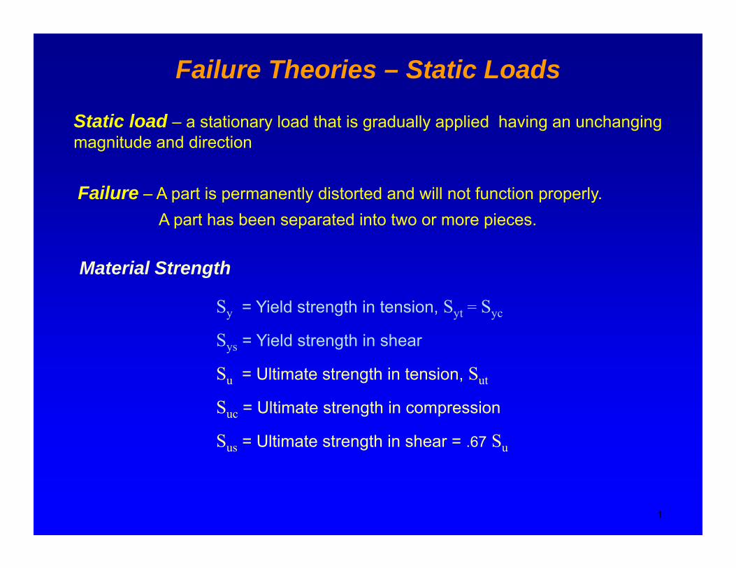
Failure Theories – Static Loads
Static load – a stationary load that is gradually applied having an unchanging magnitude and direction
Failure – A part is permanently distorted and will not function properly. A part has been separated into two or more pieces.
Material Strength
Sy = Yield strength in tension, Syt = Syc
Sys = Yield strength in shear
Su = Ultimate strength in tension, Sut
Suc = Ultimate strength in compression
Sus = Ultimate strength in shear = .67 Su
1

Ductile and Brittle MaterialsA ductile material deforms significantly before fracturing. Ductility is measured g y g yby % elongation at the fracture point. Materials with 5% or more elongation are considered ductile.
Brittle material yields very little before fracturing, the yield strength is approximately the same as the
lti t t th i t i Th lti t t th i
Mechanical Engineering Dept., SJSU 2
ultimate strength in tension. The ultimate strength in compression is much larger than the ultimate strength in tension.
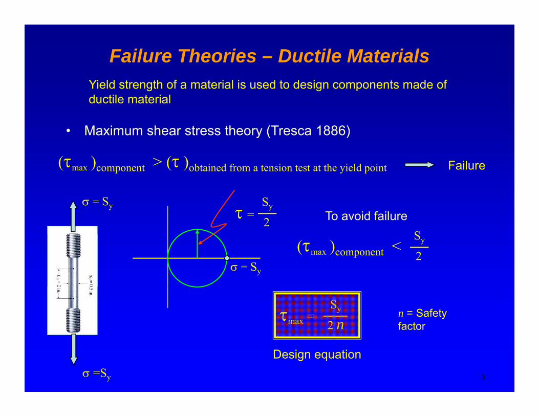
Failure Theories – Ductile Materials
• Maximum shear stress theory (Tresca 1886)
Yield strength of a material is used to design components made of ductile material
• Maximum shear stress theory (Tresca 1886)
(τmax )component > (τ )obtained from a tension test at the yield point Failure
τSy
2=σ = Sy
STo avoid failure
σ = Sy
(τmax )component < Sy
2
τmax = Sy
2 nn = Safety factor
3σ =Sy
Design equation

Failure Theories – Ductile MaterialsDi t ti th ( Mi H k )• Distortion energy theory (von Mises-Hencky)
Hydrostatic state of stress → (Sy)hSimple tension test → (Sy)t
σhσt
(Sy)t(Sy)h >>
σhDistortion contributes to failure much more than change in volume
σhchange in volume.
σt
(total strain energy) – (strain energy due to hydrostatic stress) = strain energy f
4
due to angular distortion > strain energy obtained from a tension test at the yield point → failure
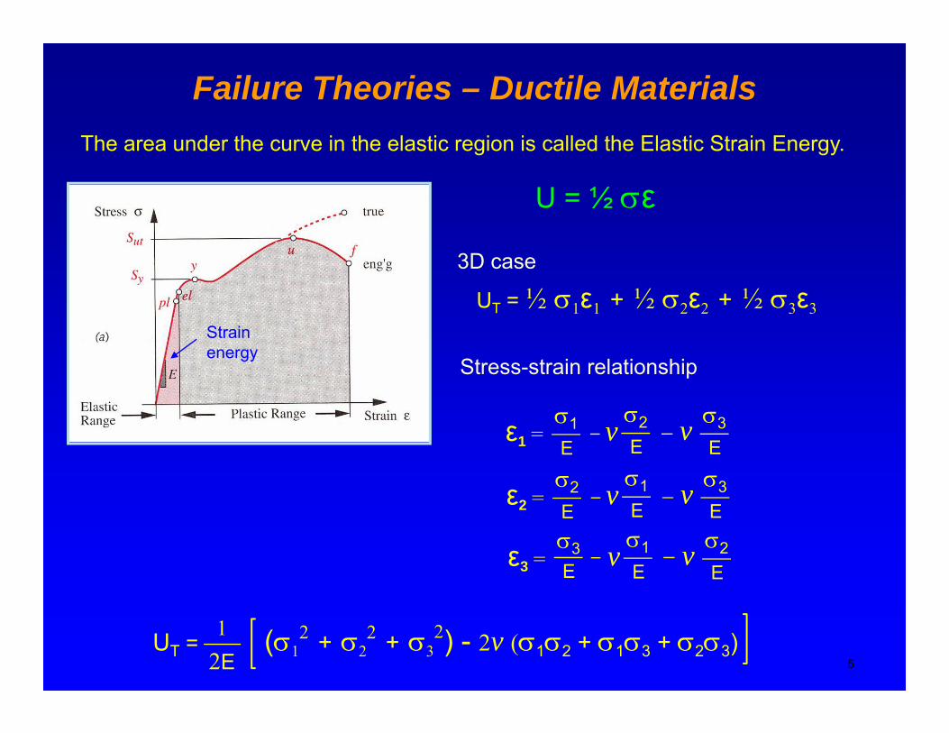
Failure Theories – Ductile MaterialsTh d h i h l i i i ll d h El i S i EThe area under the curve in the elastic region is called the Elastic Strain Energy.
U = ½ σε
3D case
UT = ½ σ1ε1 + ½ σ2ε2 + ½ σ3ε3Strain energy
σ σ σ
Stress-strain relationship
ε1 = σ1E
σ2E
σ3E
vv
ε2 = σ2E
σ1E
σ3E
vv2 E E E
ε3 = σ3 σ1
Eσ2E
vvE
5UT = (σ1
2 + σ22 + σ3
2) - 2v (σ1σ2 + σ1σ3 + σ2σ3) 2E1

Failure Theories – Ductile MaterialsDistortion strain energy = total strain energy – hydrostatic strain energy
Ud = UT – Uh
Distortion strain energy total strain energy hydrostatic strain energy
U ( 2 2 2) 2 ( )1 (1)
Substitute σ1 = σ2 = σ3 = σh
UT = (σ12 + σ2
2 + σ32) - 2v (σ1σ2 + σ1σ3 + σ2σ3)2E
1 (1)
Uh = (σh2 + σh
2 + σh2) - 2v (σhσh + σhσh+ σhσh)2E
1
Simplify and substitute σ1 + σ2 + σ3 = 3σh into the above equation
U (1 2v)3σh
2 (1 – 2v)(σ1 + σ2 + σ3)2
Uh = (1 – 2v) =2E 6ESubtract the hydrostatic strain energy from the total energy to obtain the distortion energy
6
Ud = UT – Uh =6E
1 + v (σ1 – σ2)2 + (σ1 – σ3)2 + (σ2 – σ3)2 (2)
Failure Theories – Ductile Materials
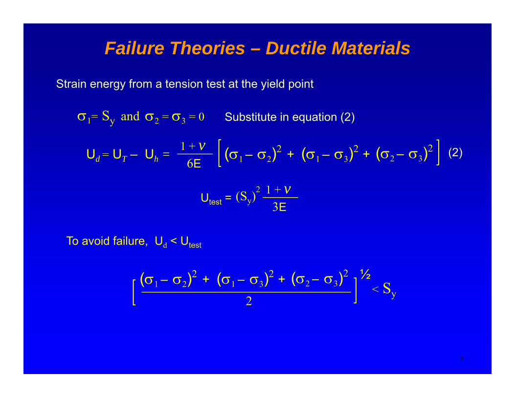
Strain energy from a tension test at the yield point
σ1= Sy and σ2 = σ3 = 0 Substitute in equation (2)y 2 3
Ud = UT – Uh =6E
1 + v (σ1 – σ2)2 + (σ1 – σ3)2 + (σ2 – σ3)2 (2)
3E1 + v(Sy)
2Utest =
To avoid failure, Ud < Utest
( )2 ( )2 ( )2 ½(σ1 – σ2)2 + (σ1 – σ3)2 + (σ2 – σ3)2
2
½< Sy
7
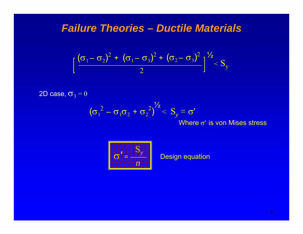
Failure Theories – Ductile Materials
(σ1 – σ2)2 + (σ1 – σ3)2 + (σ2 – σ3)2
2
½< Sy
½2D case, σ3 = 0
2
½(σ1
2 – σ1σ2 + σ22) < Sy = σ′
Where σ′ is von Mises stress
σ′ = Sy Design equationn
8

Failure Theories – Ductile Materials
Pure torsion, τ = σ1 = – σ2
(σ 2 – σ σ + σ 2) = S 2(σ1 σ2 σ1 + σ2 ) = Sy
3τ2= Sy
2 Sys = Sy / √ 3 → Sys = .577 Sy
Relationship between yield strength in tension and shear
If σy = 0, then σ1, σ2 = σx/2 ± [(σx)/2]2 + (τxy)2
the design equation can be written in terms of the dominant
2 2 S1/2
the design equation can be written in terms of the dominant component stresses (due to bending and torsion)
Mechanical Engineering Dept., SJSU 9
(σx)2
+ 3(τxy)2
=Sy
n

Design ProcessMaximum shear stress theoryDistortion energy theory
σ′ = Sy
nτmax =
Sy
2n
• Select material: consider environment, density, availability → Sy , Su
• Choose a safety factor n CostWeightSize
The selection of an appropriate safety factor should be based on the following:
Degree of uncertainty about loading (type, magnitude and direction)
Degree of uncertainty about material strength
Type of manufacturing process
Uncertainties related to stress analysis
Consequence of failure; human safety and economics
10
Type of manufacturing process
Codes and standards

Design Process
Use n = 1.2 to 1.5 for reliable materials subjected to loads that can be determined with certainty.
Use n = 1.5 to 2.5 for average materials subjected to g jloads that can be determined. Also, human safety and economics are not an issue.
Use n = 3.0 to 4.0 for well known materials subjected to uncertain loads.
11
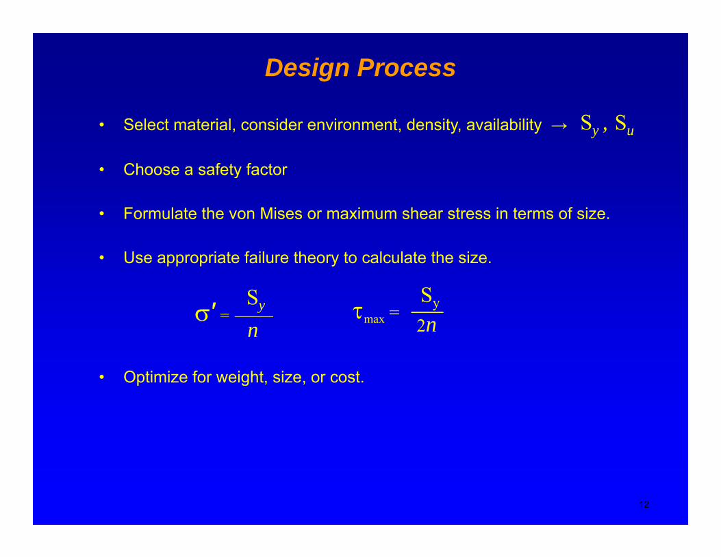
Design Process
• Select material, consider environment, density, availability → Sy , Su
• Choose a safety factor
• Formulate the von Mises or maximum shear stress in terms of size.
Choose a safety factor
• Use appropriate failure theory to calculate the size.
σ′ =Sy τ =
Sy
• Optimize for weight, size, or cost.
σ =n
τmax = 2n
p g , ,
12
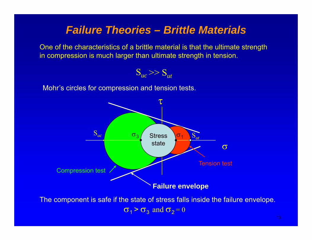
Failure Theories – Brittle MaterialsO f h h i i f b i l i l i h h l i hOne of the characteristics of a brittle material is that the ultimate strength in compression is much larger than ultimate strength in tension.
Suc >> S tSuc >> Sut
Mohr’s circles for compression and tension tests.
τ
Suc Sσ3 σ1StressSuc
Tension test
σSutσ3 σ1Stress
state
Compression test
Failure envelope
e s o test
13
The component is safe if the state of stress falls inside the failure envelope.σ1 > σ3 and σ2 = 0
Failure Theories – Brittle MaterialsModified Coulomb-Mohr theory
Sσ3 or σ2
σ3 or σ2
σ1Sut
Sut
Safe Safe
σ1Sut
Sut
I1
Suc
Safe
Safe
-Sut
σ1
-Sut
II
III
Suc Suc
III
uc
Cast iron data
uc
Three design zones
14
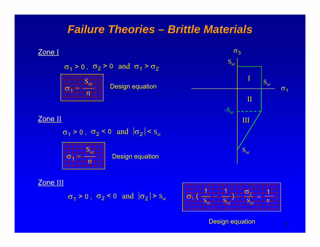
Failure Theories – Brittle Materials
σ3
Sut
I
Zone I
σ1 > 0 , σ2 > 0 and σ1 > σ2
σ1Sut
S
I
IIσ1 =
Sut
nDesign equation
-Sut
IIIZone II
σ1 > 0 , σ2 < 0 and σ2 < Sut
Sucσ1 =
Sut
n Design equation
Zone III
σ1 > 0 , σ2 < 0 and σ2 > Sut σ1 (1S
1S
– ) – σ2
S =1n
15
Sut Suc Suc n
Design equation


