Journal of Energy Technologies and Policy www.iiste.org
ISSN 2224-3232 (Paper) ISSN 2225-0573 (Online)
Vol.5, No.12, 2015
1
Experimental Evaluation of Thermal Performance of Solar
Assisted Air Conditioning System under Iraq Climate
Mohammed A. Abid Najim A. Jassim
Department of Mechanical Engineering, University of Baghdad, Baghdad, Iraq
Abstract
In Iraq most of the small buildings deployed a conventional air conditioning technology which typically uses
electrically driven compressor systems which exhibits several clear disadvantages such as high energy
consumption, high electricity peak loads demand. Because of the high energy cost, the decrease of fossil fuel
resources, the utilization of low level renewable energy sources such as solar energy in refrigeration systems has
become a way to address these problems. So a thermal performance of air conditioning system combined with a
solar collector is investigated experimentally. The hybrid air conditioner consists of a semi hermetic compressor,
water cooled shell and tube condenser, thermal expansion valve and coil and tank evaporator. Different
experimental tests were conducted by varying the controlling parameters to investigate their effects on the thermal
performance of the solar assisted air-conditioning .The parameters are cooling water flow rate, evaporator water
temperature, ambient temperature, refrigerant mass flow rate, storage tank water temperature, and solar radiation
intensity under meteorological condition of Baghdad in summer 2015. Results showed that the compressor power
consumption was decreased from 1.2 kW at collector heat gain 0.543 kW and solar radiation 572 W/m2 to 0.9 kW
at heat gain 0.831 kW and solar radiation 725 W/m2, this leads to increase in COP from 2.493 to 2.725. A
comparison between the present experimental work and the other works showed a similar behavior. Result shows
an average energy saving of power consumption is about between 23% and 32%.
Keywords: solar assisted air conditioning system, solar collector, thermal performance.
1. Introduction
The increasing consumption of energy in buildings on air-conditioning systems has initiated a great deal of
research aiming at energy savings. With the consolidation of the demand for human comfort, around 48% of energy
is consumed in commercial and public buildings due to air conditioners, usually by driving electrical vapour
compression chillers (Lamberts, 1999). The use of solar thermal energy for air-conditioning in hot and sunny
climate is a promising new application of solar collectors in buildings. The main advantage of the solar air
conditioning system is that in solar air conditioning applications solar gains and cooling loads occur at the same
time and on the seasonal level. Iraq is one of the countries with the highest electricity production from oil during
2008(IEA i.e., 2011). (Vakiloroaya et.al 2013) developed a solar-assisted air conditioner system to performance
enhancement and energy efficiency improvement. A novel configuration include a by-pass line that connected
with a three way proportional control valve which is proposed a discharge line after the compressor to control the
flow rate of refrigerant. In this design, the flow rate of refrigerant can be controlled as a function of the temperature
of refrigerant leaving compressor, the temperature of refrigerant leaving the solar storage tank and the temperature
of ambient dry-bulb. The novel development was promising for the improvement of energy efficiency,
enhancement of the performance of system while fulfilling the cooling demand. Consequently, about 43% of
monthly electricity consumptions can be saved on average. (Al-Alili et.al, 2013) investigated a novel application
for hybrid photovoltaic thermal (PVT) collector, which produces hot water and electricity simultaneously. The
hybrid collector used to drive hybrid air conditioner that separates the latent and sensible loads. The hybrid air
conditioner consisted of solid desiccant wheel cycle (DWC) and conventional vapor compression cycle (VCC).
The desiccant wheel cycle was driven by a collector thermal output and the vapor compression cycle is driven by
an electrical output. The performance of system was modeled by using Transient System Simulation program and
Abu Dhabi weather condition. A parametric study carried out to study the key parameters effect on the performance
of solar air conditioner. The performance of the overall system was also compared to the performance of the vapor
compression cycle, which was widely used in UAE, powered by photovoltaic panels and the solar absorption cycle
was driven by evacuated tube collectors. The results showed that the decoupling of the sensible and latent loads
was so effective in meeting the temperature and humidity requirements of buildings in humid and hot climates.
The overall coefficient of performance of the system was found to be higher of the year than the coefficient of
performance of the other solar air conditioners. (Vakiloroaya et.al 2013) investigated an experimental study of the
operational characteristics of the new direct-expansion air conditioning system that combined with vacuum solar
collector. The mathematical models of the system components were firstly derived and then validate against the
experimental results. To investigate the potential energy savings, the solar-assisted air-conditioner was installed
and extensively equipped with some sensors and instrumentation devices. The influence on the energy usage of
the room set-point temperature, storage tank size and average water temperature were then analyzed. Once the air-
conditioned room had achieved its desired temperatures, while the cooling process still continues, the compressor

Journal of Energy Technologies and Policy www.iiste.org
ISSN 2224-3232 (Paper) ISSN 2225-0573 (Online)
Vol.5, No.12, 2015
2
turns off until the pressure of refrigerant no longer maintains its desired temperature. The advantages of this
proposed hybrid system is rested with the fact that the compressor can still remain off in a longer period by the
heat impartation into the refrigerant in the water storage tank. Results showed a good energy saving. The present
study is aimed to evaluate of the effects of various operating parameters such as ambient temperature, solar
intensity, and demand on the coefficient of performance, cooling capacity and power consumption by the vapor
compression refrigeration system.
2. Description of the experimental apparatus:
The prototype consisted of three different process fluid loops; air-conditioning loop, the collector loop, and cooling
tower loop. Fig.1 presents the piping diagram of the entire prototype, including all instrumentation installed in the
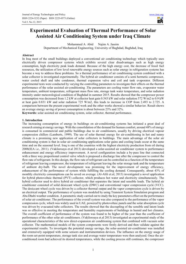
system, in which all three loops are clearly labeled. The experimental apparatus is shown photographically in
plate.1.
Figure 1. Schematic of the apparatus highlighting instrumentation
Compressor
condenserr
Filter dryer
Solenoid valve
Expansion valve
Evaporator tank
Sight glass
Storage tank
Journal of Energy Technologies and Policy www.iiste.org
ISSN 2224-3232 (Paper) ISSN 2225-0573 (Online)
Vol.5, No.12, 2015
3
Plate 1. Photograph of the experimental apparatus.
2.1 Air-conditioning loop
The air-conditioning loop was connected in series between the charge loop and the cooling tower loop. Heat was
transferred between the loops with the use of two heat exchangers. The components of the air-conditioning loop
were a semi hermetically sealed reciprocating compressor, solar heat exchanger, condenser, a thermostatic
expansion valve which throttled the flow and maintained a constant superheat temperature exiting the evaporator
and evaporator. The high pressure side of the air-conditioning was constructed using 3/8" refrigeration grade
copper tubing, and the low side was constructed using 5/8'' copper tubing. The bypass installed after compressor
to control the flow rate of the refrigerant and the load on the compressor.
2.2 Collector loop
In a typical solar heating system, the collector loop transfers heat from the solar collectors to the balance of the
system, this loop consist of evacuated tube solar collector , circulating water pump and heat exchanger.
2.2.1 Evacuated tube solar collector
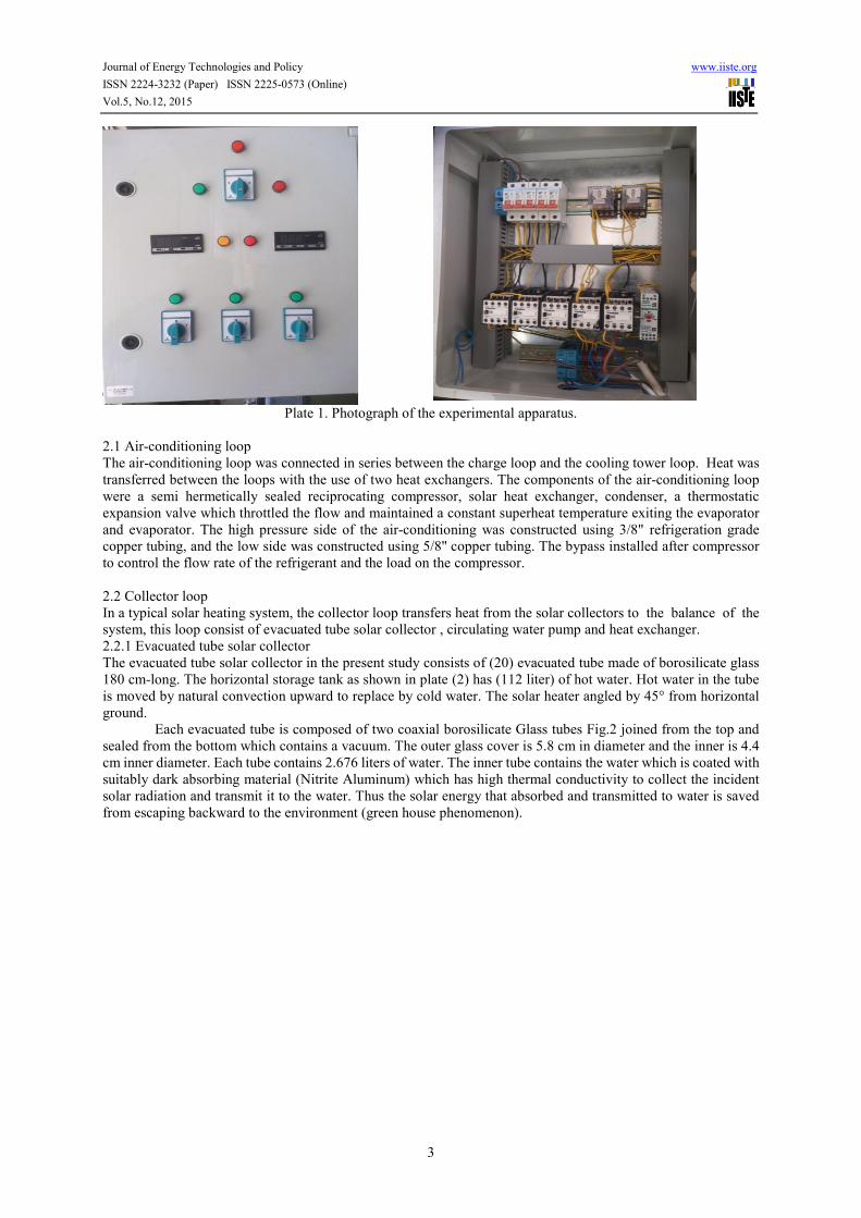
The evacuated tube solar collector in the present study consists of (20) evacuated tube made of borosilicate glass
180 cm-long. The horizontal storage tank as shown in plate (2) has (112 liter) of hot water. Hot water in the tube
is moved by natural convection upward to replace by cold water. The solar heater angled by 45° from horizontal
ground.
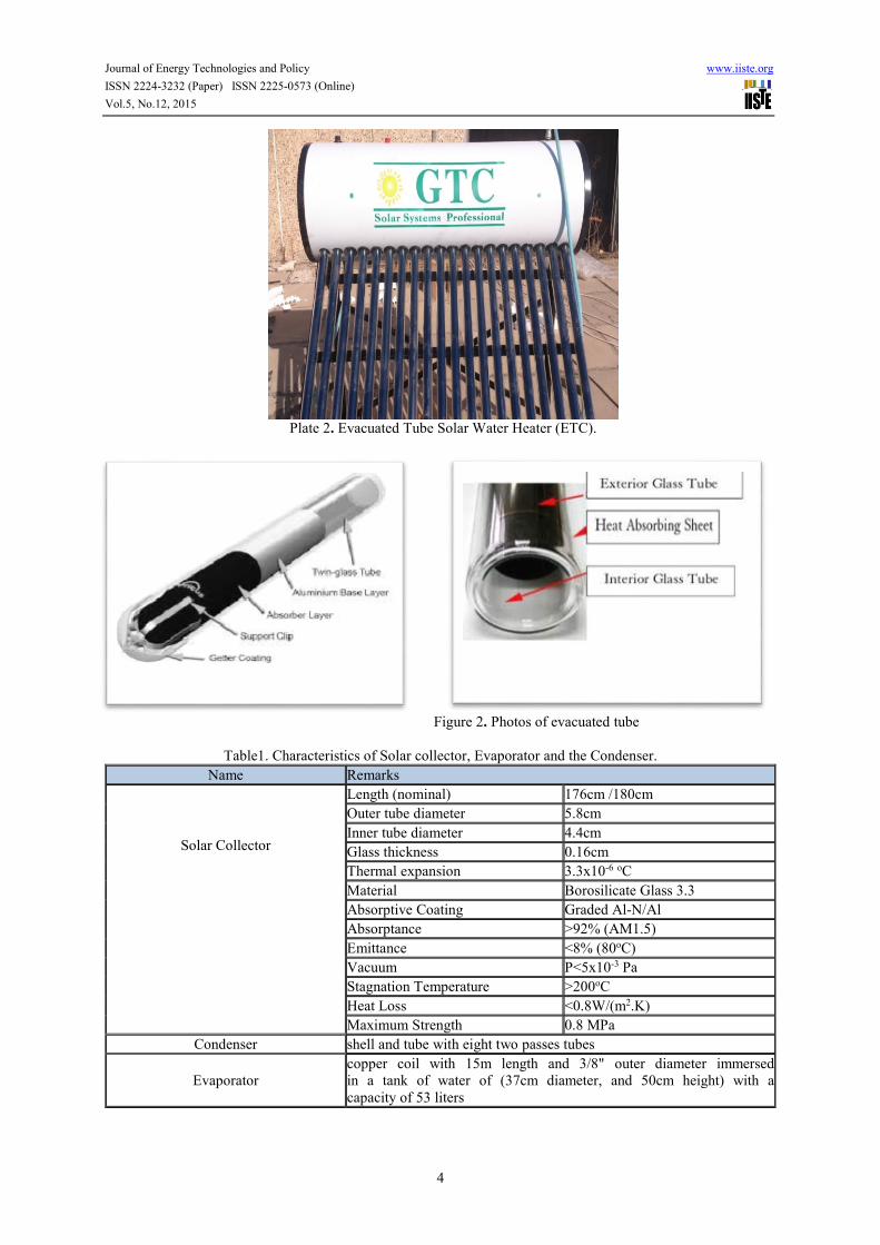
Each evacuated tube is composed of two coaxial borosilicate Glass tubes Fig.2 joined from the top and
sealed from the bottom which contains a vacuum. The outer glass cover is 5.8 cm in diameter and the inner is 4.4
cm inner diameter. Each tube contains 2.676 liters of water. The inner tube contains the water which is coated with
suitably dark absorbing material (Nitrite Aluminum) which has high thermal conductivity to collect the incident
solar radiation and transmit it to the water. Thus the solar energy that absorbed and transmitted to water is saved
from escaping backward to the environment (green house phenomenon).
Journal of Energy Technologies and Policy www.iiste.org
ISSN 2224-3232 (Paper) ISSN 2225-0573 (Online)
Vol.5, No.12, 2015
4
Plate 2. Evacuated Tube Solar Water Heater (ETC).
Figure 2. Photos of evacuated tube
Table1. Characteristics of Solar collector, Evaporator and the Condenser.
Name Remarks
Solar Collector
Length (nominal) 176cm /180cm
Outer tube diameter 5.8cm
Inner tube diameter 4.4cm
Glass thickness 0.16cm
Thermal expansion 3.3x10⁻⁶ oC
Material Borosilicate Glass 3.3
Absorptive Coating Graded Al-N/Al
Absorptance >92% (AM1.5)
Emittance <8% (80oC)
Vacuum P<5x10⁻³ Pa
Stagnation Temperature >200oC
Heat Loss <0.8W/(m2.K)
Maximum Strength 0.8 MPa
Condenser shell and tube with eight two passes tubes
Evaporator
copper coil with 15m length and 3/8" outer diameter immersed
in a tank of water of (37cm diameter, and 50cm height) with a
capacity of 53 liters
Journal of Energy Technologies and Policy www.iiste.org
ISSN 2224-3232 (Paper) ISSN 2225-0573 (Online)
Vol.5, No.12, 2015
5
2.3 Cooling tower loop
This loop consist of a cross- flow water type cooling tower, heat exchanger (condenser) which was discussed in
the previous section and a circulating water pump. Cooling tower used to cool water that used to condense the
refrigerant.
2.3.1 Cooling tower
A cross-flow water cooling tower has the dimension of (760 mm ×740 mm × 970 mm) was used. A 1 inch (25.4
mm) copper tube having nine nozzles was used to distribute the water over the water distributer basin which was
made of (3 mm) thick Perspex colorless plate with (23 × 8) number of holes. These holes are of (3mm) diameter
arranged in such a way that the drops of water are evenly distributed over the packing.
The distributing basin is covered with flat asbestos plate to avoid water leakage and also to reduce
evaporation losses from the hot water.
A water droplet eliminator is installed before the fan which is made of galvanized steel sheet (730
mm×950 mm ) and meshed with ( 26 × 4 ) slots at an angle of about ( 30° - 45° ) having a length ( 150 mm) and a
width of (10 mm). The propeller fan has four blades and (600 mm) diameter pulley powered using v –belt by an
induction motor of (2880 rpm) single phase, (0.3725 KW) with (90 mm) diameter pulley giving a fan speed of
(432 rpm).The packing used was of corrugated asbestos type, this packing having a dimension of (750 mm × 300
mm × 10 mm).
3. Instrumentations and measurements
In order to determine the performance of the prototype under various conditions, the apparatus was equipped with
the necessary instrumentation. A schematic diagram of the apparatus is shown in Fig.1, demonstrating the
positioning of the instrumentation within the prototype. Only the major components of the system are shown in
this Figure for simplicity. Many measuring devices were used to sense the variation of cooling water temperatures
& flow rate, heating water temperatures & flow rate, refrigerant temperatures, low and high pressures along the
air-condition , electrical voltage & current, air temperatures and Solar radiation intensity.
4. Results and discussions
4.1 Effect of evaporator water temperature
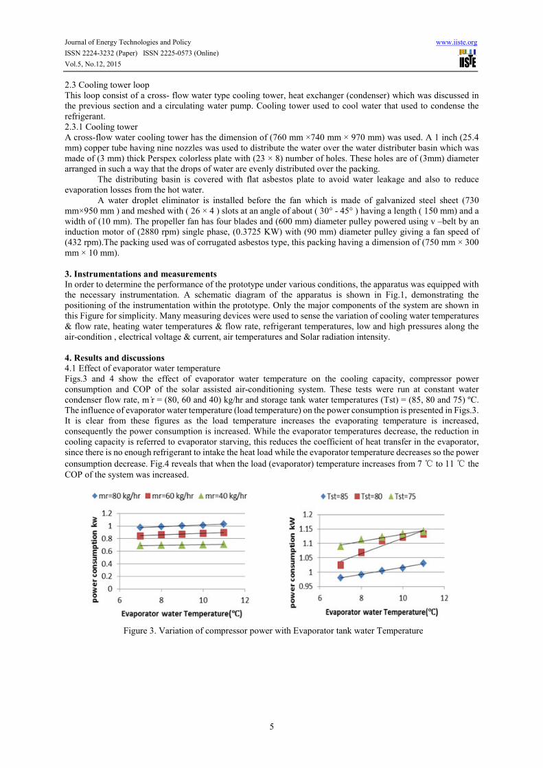
Figs.3 and 4 show the effect of evaporator water temperature on the cooling capacity, compressor power
consumption and COP of the solar assisted air-conditioning system. These tests were run at constant water
condenser flow rate, m ̇r = (80, 60 and 40) kg/hr and storage tank water temperatures (Tst) = (85, 80 and 75) ºC.
The influence of evaporator water temperature (load temperature) on the power consumption is presented in Figs.3.
It is clear from these figures as the load temperature increases the evaporating temperature is increased,
consequently the power consumption is increased. While the evaporator temperatures decrease, the reduction in
cooling capacity is referred to evaporator starving, this reduces the coefficient of heat transfer in the evaporator,
since there is no enough refrigerant to intake the heat load while the evaporator temperature decreases so the power
consumption decrease. Fig.4 reveals that when the load (evaporator) temperature increases from 7 ℃ to 11 ℃ the
COP of the system was increased.
Figure 3. Variation of compressor power with Evaporator tank water Temperature

Journal of Energy Technologies and Policy www.iiste.org
ISSN 2224-3232 (Paper) ISSN 2225-0573 (Online)
Vol.5, No.12, 2015
6
Figure 4. Variation of COP with Evaporator tank water Temperature
4.2 Effect of condenser water flow rate
The effect of condenser water flow on the thermal performance of the air-conditioning system was investigated in
four different values (2, 3, 4 and 5 l/min). During this investigation, the refrigerant flow rate was kept at (80, 60
and 40 kg/hr) and storage tank water temperature (Tst) at (85, 80 and 75) ºC. Fig.5 shows the effect of different
mass flow rates on compressor power consumption. The condenser temperature is affected strongly by the amount
of mass flow rate. The increase in water flow rate results decrease in the temperature of the refrigerant in the
condenser due to inverse relation between them, consequently the enthalpy difference will decreased, which will
definitely the condenser heat transfer rate decreases with increasing the water flow rate. And since an isenthalpic
expansion process is assumed for the thermostatic expansion valve, therefore the evaporator heat transfer rate will
increase with increasing cooling water flow rate. As a result of decreasing in the condenser temperature the
compressor power consumption was decreased. As a result of decreasing of the compressor power consumption
and the increasing of cooling capacity the COP of the system increased according to Eq. (1) with increasing
condenser water flow rate as shown in Fig.6.
Figure 5. Variation of compressor power with cooling water flow rate.
tCOPnconsumptiopower
capacity cooling=
(1)
Journal of Energy Technologies and Policy www.iiste.org
ISSN 2224-3232 (Paper) ISSN 2225-0573 (Online)
Vol.5, No.12, 2015
7
Figure 6. Variation of COP with cooling water flow rate.
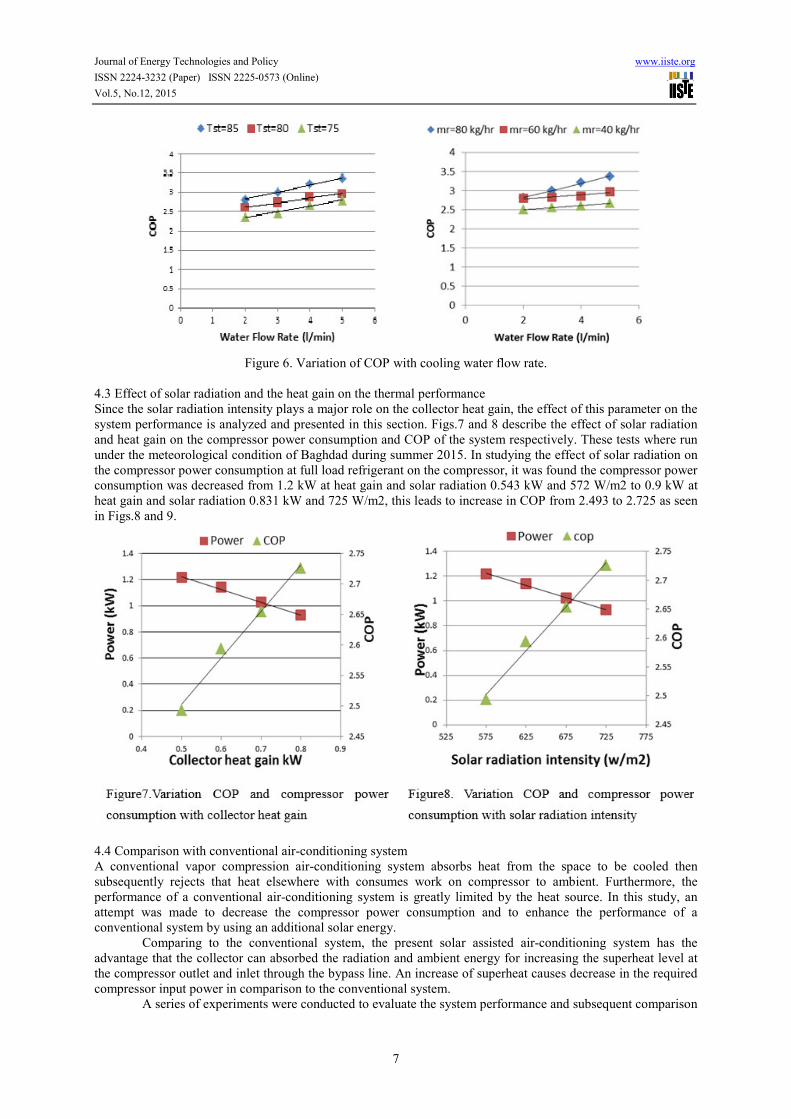
4.3 Effect of solar radiation and the heat gain on the thermal performance
Since the solar radiation intensity plays a major role on the collector heat gain, the effect of this parameter on the
system performance is analyzed and presented in this section. Figs.7 and 8 describe the effect of solar radiation
and heat gain on the compressor power consumption and COP of the system respectively. These tests where run
under the meteorological condition of Baghdad during summer 2015. In studying the effect of solar radiation on
the compressor power consumption at full load refrigerant on the compressor, it was found the compressor power
consumption was decreased from 1.2 kW at heat gain and solar radiation 0.543 kW and 572 W/m2 to 0.9 kW at
heat gain and solar radiation 0.831 kW and 725 W/m2, this leads to increase in COP from 2.493 to 2.725 as seen
in Figs.8 and 9.
4.4 Comparison with conventional air-conditioning system
A conventional vapor compression air-conditioning system absorbs heat from the space to be cooled then
subsequently rejects that heat elsewhere with consumes work on compressor to ambient. Furthermore, the
performance of a conventional air-conditioning system is greatly limited by the heat source. In this study, an
attempt was made to decrease the compressor power consumption and to enhance the performance of a
conventional system by using an additional solar energy.
Comparing to the conventional system, the present solar assisted air-conditioning system has the
advantage that the collector can absorbed the radiation and ambient energy for increasing the superheat level at
the compressor outlet and inlet through the bypass line. An increase of superheat causes decrease in the required
compressor input power in comparison to the conventional system.
A series of experiments were conducted to evaluate the system performance and subsequent comparison

Journal of Energy Technologies and Policy www.iiste.org
ISSN 2224-3232 (Paper) ISSN 2225-0573 (Online)
Vol.5, No.12, 2015
8
of the two systems. The results are presented in Figs.9 and 10.
It is clear from these figures that a higher storage temperature used results higher energy efficiency. On
other hand, the increasing of solar radiation intensity causes an increase water temperature inside the storage tank.
Thus, with a higher storage tank water temperature level, more electricity savings can be expected.
As shown in Fig.9 the compressor power consumption of the system is reduced by 31.3% at 85℃ storage
tank water temperature while it is increased by 23.9% at 75℃ storage tank water temperature as compared with
conventional system.
Consequently the COP of solar assisted air conditioning system is increased by 45.50% at 85℃ storage
tank water temperature while it is increased by 21.21% at 75℃ storage tank water temperature as compared with
conventional system, as shown in Fig.10.
4.5 Comparison between theoretical and experimental works
A simulation of the solar assisted air-conditioning system by using ESS software was done. The profile created
for this system consisted of three parameters: load temperature (7, 8, 9, 10 and 11) ℃, refrigerant mass flow rate
(40 to 80) kg/hr and ambient temperature (39 to 44) ℃ are used to determining the power consumption and energy
transfer rates .
Figs.11 to 13 show comparisons between the experimental and the theoretical results of power
consumption and the coefficient of performance of the system respectively. Fig.11 shows a reasonable comparison
of the measured power consumption and the performance of system regarding the variation of evaporation
temperature are compared to the predicted results. The deviation between the experimental and theoretical power
consumption and the performance of the system is about 0.03 and 0.12 respectively.
In Fig.12 the measured power consumption and the performance of system regarding the variation of
condensing temperature are compared to the predicted results. The deviation between the experimental and
theoretical power consumption and the coefficient of performance of the system is about 0.17 and 0.25 respectively.
Fig.13 show a reasonable comparison between the measured and predicted of cooling capacity, power
consumption and COP regarding the influence of refrigerant mass flow rate on them. The deviation between the
experimental and theoretical power consumption, cooling capacity and the performance of the system is about
0.35, 0.07 and 0.43 respectively.
Generally, this theoretical work indicates that EES software is a good tool to predict the performance of
solar assisted air conditioning system.
Figure9. Variation percentage compressor power
consumption with storage tank water temperature
18%
20%
22%
24%
26%
28%
30%
32%
74 76 78 80 82 84 86
Pe
rce
nta
ge
po
we
r co
nsu
mp
tio
n
Storage tank water temperature
Figure10. Variation percentage COP with storage tank
water temperature
0%
5%
10%
15%
20%
25%
30%
35%
40%
45%
50%
74 76 78 80 82 84 86
Pe
rce
nta
ge
CO
P %
Storage tank water temperature

Journal of Energy Technologies and Policy www.iiste.org
ISSN 2224-3232 (Paper) ISSN 2225-0573 (Online)
Vol.5, No.12, 2015
9
Figure 11. Comparison between the experimental and theoretical influence of evaporator water temperature on: A.
The power consumption B. COP
Figure 12. Comparison between the experimental and theoretical influence of condensing temperature on: A.
the power consumption B. COP

Journal of Energy Technologies and Policy www.iiste.org
ISSN 2224-3232 (Paper) ISSN 2225-0573 (Online)
Vol.5, No.12, 2015
10
Figure 13. The comparison between the experimental and theoretical influence of refrigerant mass flow rate on:
A. the power consumption B. COP C. the cooling capacity
4.6 Comparison of the present work with other works
Some of the present experimental results are compared in this section with other previous experimental works.
The comparison is a qualitative comparison and it is not a quantitive comparison, i.e. the agreement was attained
in the behavior of the characteristics and the tendency of the curves but there is no agreement in the values with
the previous works and this was shown in Figs.14 to 16.
Fig.14 shows a comparison of the present experimental results of the average energy consumption of the
conventional air conditioner and newly-developed solar-assisted air conditioning systems during the summer
season. It can be seen that the power consumption of new solar-assisted air conditioner is significantly less than
the power usage of conventional system. This behavior of average energy consumption was also mentioned by
Vakiloroaya and was apparently the same throughout this figure. To show the energy saving potential, average
COPs are compared between the newly-developed system and a conventional system of the same capacity by using
both experimental and simulation data. The comparison is shown in Fig.15 for the successive months of a hot
season of the year. It can be seen that the average coefficient of performance for the proposed system is higher
than that of a conventional one. This COP improvement can be explained by the new system’s capability of energy

Journal of Energy Technologies and Policy www.iiste.org
ISSN 2224-3232 (Paper) ISSN 2225-0573 (Online)
Vol.5, No.12, 2015
11
saving with respect to the cooling demand, which coincides with the results presented in Fig.14. This behavior of
average COP was also mentioned by Vakiloroaya and was apparently the same throughout this figure. The overall
thermal performance of the system is influenced by the operation parameters such as the storage tank average
water temperature, storage tank volume.
Fig.16 shows the comparison of the variation of the system energy consumption as a function of the water
storage tank volume for summer, where it can be seen that with the increasing storage tank volume, the electricity
power consumption decreases initially but tends to reach a minimum value asymptotically. It is interesting to note
that the storage tank volume greater than a certain volume does not have much influence on the system energy
usage. This behavior of energy consumption was also mentioned by Vakiloroaya and was apparently the same
throughout this figure.
Figure 14. Comparison of system energy consumption with the other work
Figure 15. Comparison the Coefficient of performance (COP) with other works

Journal of Energy Technologies and Policy www.iiste.org
ISSN 2224-3232 (Paper) ISSN 2225-0573 (Online)
Vol.5, No.12, 2015
12
Figure 16. Comparison the effect of the storage tank volume on power consumption with other works.
5. Conclusion
An experimental investigation of the thermal performance of the solar assisted air conditioning system has been
performed in the present work; the following conclusions are concluded:
1. The COP of the air-conditioning system increased with increasing condenser water flow rate. As a result
of decreasing in the condenser temperature that is accompanying by decreasing in the compressor power
consumption.
2. The evaporator water (load) temperature has a great influence on the thermal performance of the system.
Higher load temperature causes increase in cooling capacity which overcomes the increase in compressor power
consumption. Consequently the COP of the system is decreased.
3. The collector heat gain was increased with increasing the solar radiation, this leads to decrease the
compressor power consumption from 1.2 kW when the heat gain of 0.543 kW at a solar radiation of 572 W/m2 to
0.9 kW when the heat gain of 0.831 kW at a solar radiation of 725 W/m2. Consequently the COP is increased from
2.493 to 2.725.
References
Ali M. AL-Salihi, et al. (2010), Estimation of Global Solar Radiation on Horizontal Surface Using Routine
Meteorological Measurements for Different Cities in Iraq .Asian Journal of Scientific Research, 2010. 3 (4), p.p :
240-248 .
Lamberts (1999), R. Energy Efficiency in Buildings in Brazil (March 1999): Towards a Standard. Report presented
to the International Energy Initiative.
Presentation “Effective Solar Chilled Water” (June 2009) by Bud Leavell Yazaki Energy Systems Inc. Plano,
Texas.
Kraas, F. (2003): Megacities as Global Risk Areas. (Petermanns Geographische Mitteilungen 147 (4): 6-15.
Spangenberg, J. (2004): Improvement of urban climate in tropical metropolis, Master´s Thesis - University of
Applied Sciences Cologne (Institute for Technologies in the Tropics).
Solair (2009): Requirements on the Design and Configuration of Small and Medium Sized Solar Air-conditioning
Applications – Guidelines.
Duffie, J., & Beckman, W. (2006). Solar Engineering of Thermal Processes. (3rd, Ed.) Hoboken, NJ: John Wiley
& Sons, Inc.
Florides, G.A., Kalogirou, S.A., Tassou, S.A., Wrobel, L.C., 2002. Modeling and simulation of an absorption solar
cooling system for Cyprus. Solar Energy 72 (1), 43‒51.
The History of Air Conditioning Lou Kren, Properties Magazine. Inc. Retrieved 1 January 2007.
History of Air Conditioning Source: Jones Jr., Malcolm. "Air-Conditioning". Newsweek. Winter 1997 v130 n24-

Journal of Energy Technologies and Policy www.iiste.org
ISSN 2224-3232 (Paper) ISSN 2225-0573 (Online)
Vol.5, No.12, 2015
13
A p42 (2). Retrieved 1 January 2007.
Birch, T. W.(2003), Automotive Heating and Air Conditioning, 3rd ed. Upper Saddle River, N.J: Prentice Hall.
Haresh Khemani (2009), Fluid Flow Visualization - Timelines, Pathlines, Streaklines and Streamlines, Bright Hub.
31 Aug. 2009. Web. 04 Dec. 2010.
<http://www.brighthub.com/engineering/civil/articles/47653.aspx>.
Mohamed H. B. Abdul Jalil (2012), Simulation of Performance of Air Conditioning system, (June 2012). Faculty
of Mechanical Engineering University Malaysia Pahang.
V. Vakiloroaya, et al. (2012). Experimental Study of a New Solar Assisted Air-Conditioner for Performance
Prediction and Energy Saving. School of Electrical, Mechanical and Mechatronic Systems, University of
Technology, Sydney, Australia.
V. Vakiloroaya, et al. (2013). Modeling and Experimental Validation of a Solar-Assisted Direct Expansion Air
Conditioning System.
Al-Alili A, Hwang Y, Radermacher R, Kubo I. A high efficiency solar air conditioner using concentrating
photovoltaic/thermal collectors. Applied Energy; vol. 93, 2012, pp. 138-147.
Henning (2007), H. Solar Assisted Air Conditioning of Buildings-an overview. Applied Thermal Eng., vol.27,
2007, pp. 1734-1749.


