EXPERIENCE OF JOINING OF HIGH STRENGTH AUTOMOTIVE SHEET IN THE BODY SHOP
Hans Hornig
BMW Group 80788 München, Germany
Abstract
In addition to lightweight design, central topics in modern automotive engineering are the continuous optimization of active and passive safety, of corrosion protection and of the general properties in terms of usage and function of the overall vehicle. In order to achieve optimal functionality, economic efficiency and, eventually optimized vehicle weight, the process engineers and design engineers daily face new challenges. Important milestones to achieve these targets are the selective use of new and advanced materials and the provision of proven product,- joining-, testing- and repair processes. In particular the variety of materials expected in the future, once again poses new challenges to the joining and connection technology. Existing joining processes (e.g. resistance welding, shielded arc welding and brazing, laser welding, stud welding, adhesive bonding, self pierce rivet) must be further developed and be supplemented by new process variants. The design of joined components of vehicle structures so that they can achieve required service performance limits without an increase of vehicle weight or cost is of paramount importance to automotive manufacturers. Achieving this goal requires careful selection of, both, steel material and joining technique as well as detailed knowledge of the elastic and plastic behavior of the joined sections, particularly under cyclic loading. This also includes new procedures for the release of new materials and processes from the viewpoint of joining technology. Based on examples of new material and body concepts applied within the BMW Group a report on the results and experience gathered in the application of various joining processes is given.
Introduction
Technological development in the Automotive Industry as well as its commercialization caused, among others, the following: Customers more and more associates the properties “light-weight”and ‘fuel-efficient’ with the development standard and attractiveness of a vehicle type. Light weight design thus has commenced to become the central subject of Automotive Engineering, but also of Mechanical Engineering in general. Consequent lightweight design will have benefits there, where energy saving and weight reduction at moved masses can be reached. Therefore light weight design offers excellent chances for product innovation and is essentially characterized by some fundamental approaches. The classic lightweight design approach envisages the application of light materials and high strength to ultra high strength materials. Other approaches prefer the realization of progressive, problem-adapted structures, an exact registration of the strain and stress condition as well as stress-optimized dimensioning. Here distinctions are drawn between material lightweight design, shape light-weight design and concept light weight design. An optimum product design, however, is only reached by a combination of such measures at a justified cost benefit analysis. Therefore lightweight design has to be analyzed and checked at large considering aspects with respect to material engineering, design and production engineering. This is the only means to efficiently tap the existing
129
International Symposium on Niobium Microalloyed Sheet Steel for Automotive ApplicationEdited by S. Hashimoto, S. Jansto, H. Mohrbacher, and F. Siciliano
TMS (The Minerals, Metals & Materials Society), 2006

lightweight design potential and to implement the new materials acc. to their extended capacity. Lightweight design poses a large challenge for the joining technology also. Here it is necessary to extend the performance of the diverse joining methods and supplement these with new processes to fulfill the challenges in regard to new designs and material combinations. Implementation of high strength and higher strength steel material in the body shop require e.g. ductile, strain suitable and safely applicable joins, withstanding the stresses of the lightweight design. For mixed connections (e.g. steel with aluminum) safe and reproducible methods shall be developed and implemented also. Experiences made in the last few years demonstrated that a process chain interdisciplinary examination of the manufacturing process (material, press plant, body shop, surface technology and corrosion technology) is a purposeful and especially mandatory measure. Within this context it has to be considered that the different lightweight design approaches will introduce more complexness in the modern manufacturing process, challenging men (process comprehension) and machine (higher performance) to a great extent. Following, experiences from the joining technology field within the body shop are reported.
Targets and Requirements for Using Multiphase Steel
Figure 1 shows the international NCAP test created for newly developed vehicle bodies. To achieve the requested features - especially in the area of passive and active protection of persons – modern vehicle development is subject to special rules. Hereby the engineer is complied to realize the objectives of ergonomic lightweight design and the optimum on the focus of joinability in addition to the safety aspect.
For this purpose, there are different possibilities. On the one hand conceptual lightweight design is exercised as in the current BMW 5-series with the aluminum front end. While on the other hand lightweight design is executed with shapes based on the hydroforming technique.
Front crash (64 kph) Pole test (29 kph)
ENCAP: European New Car Assessment Program
Figure 1. New car assessment program - High-Strength Steel Body ENCAP Crash Test BMW 3-Series.
130

Shape
Material
Concept
Weight CostsFunction
Light-WeightDesign
Figure 2. Means to Lightweight Design.
With this option many reinforcement parts can be omitted. With the development of high strength and higher-strength steel materials, at a reduced sheet thickness material lightweight design gains more and more importance. In addition to the functional features and the weight reduction – due to all listed potentials of the light-weight-design - the calculated cost-specifications for a body shall be observed. This poses a challenge for steel and car manufacturers (Figure 2).
Load suitable thin walled sheet materials are provided for each body variant with the aid of certain measures at the manufacturing as well as with intelligent alloy combinations (Figure 3). However, an optimum fulfillment of the functions and weight reduction exists from the material point of view with the disadvantage of a higher complexness due to the multi material implementation (documentation, logistic).
Material
Function for customer
Demands ofbody component
Demands ofproduction
• Joinability• Weldability• Formability
• Light-weight design• Static stiffness• Crashworthiness• Deformation volume
Figure 3. Demands on high strength steel for car body.
131

Important factors, for example, the weldability and joinability, however, are often under estimated or completely ignored. The ability for repair of new vehicle structures shall be clarified explicitly and shall be assured methodologically.
Steel Sheet Material Use in BMW 3-series
After the clarification of all facts and the solution of all joining related individual questions the optimized high strength and higher strength material implementation was realized for the new BMW 3-series with a proportion of 68 per cent (Figure 4). Here functionally optimized-materials and materials optimized in utilization were implemented with tensile strengths of up to 950 MPa. This is illustrated in the Figure 4 by the different colors of the individual body parts and assembly groups.
Steel gradeOtherDC 03/04/06DX 54DX 56180 MPa220 MPa260 MPa300 MPa340 MPa380 MPa400 MPa420 MPa500 MPa680 MPa950 MPa
Plastic
Figure 4. Steel grades used in BMW 3 series.
Proceedings for testing of joint- and weldability
The ability to process and to join materials had to be considered in the early project phase of the new model with respect to the overall process chain "Painted Body”. This is an important consideration for joining engineers, since not everything with weldability can be transformed and painted or will meet the function. For the assurance of the welding suitability and the welding process, exact material data sheets and transformation diagrams were requested from the steel manufacturers (Figure 5).
This was the only means to establish a relationship of the present material and the welding results and a way, to comment the results. Accurate procedures for the joining related qualification had to be determined anew. According to the complexness of the material and the joining task process tests upon the test metal sheets were insufficient and had to be complemented by component tests (Figure 6).
132
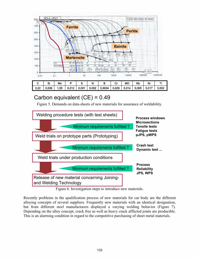
Carbon equivalent (CE) = 0.49
0,0020,0170,0050,0140,0290,00040,0020,0010,0121,550,0360,22
TiNiNbMOCrBNSPMnSiC
0,0020,0170,0050,0140,0290,00040,0020,0010,0121,550,0360,22
TiNiNbMOCrBNSPMnSiC
Perlite
Bainite
Ferrite
Martensite
Figure 5. Demands on data-sheets of new materials for assurance of weldability.
Welding procedure tests (with test sheets)
Weld trials on prototype parts (Prototyping)
Weld trials under production conditions
Release of new material concerning Joining-and Welding Technology
Minimum requirements fulfilled ?
Crash testDynamic test ...
Process windowsMicrosectionsTensile testsFatigue testspJPS, pWPS
Minimum requirements fulfilled ?
ProcessReliabilityJPS, WPS
Minimum requirements fulfilled ?
Figure 6. Investigation steps to introduce new materials.
Recently problems in the qualification process of new materials for car body are the different alloying concepts of several suppliers. Frequently new materials with an identical designation, but from different steel manufacturers displayed a varying welding behavior (Figure 7). Depending on the alloy concept, crack free as well as heavy crack afflicted joints are producible. This is an alarming condition in regard to the competitive purchasing of sheet metal materials.
133
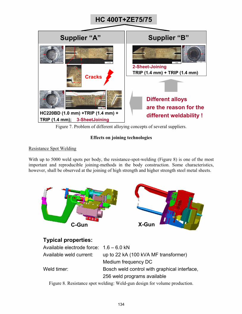
Supplier “A” Supplier “B”
Cracks
HC220BD (1.0 mm) +TRIP (1.4 mm) +TRIP (1.4 mm); 3-SheetJoining
Different alloysare the reason for thedifferent weldability !
HC 400T+ZE75/75
2-Sheet-JoiningTRIP (1.4 mm) + TRIP (1.4 mm)
Figure 7. Problem of different alloying concepts of several suppliers.
Effects on joining technologies
Resistance Spot Welding
With up to 5000 weld spots per body, the resistance-spot-welding (Figure 8) is one of the most important and reproducible joining-methods in the body construction. Some characteristics, however, shall be observed at the joining of high strength and higher strength steel metal sheets.
X-GunC-Gun
Typical properties:Available electrode force: 1.6 – 6.0 kNAvailable weld current: up to 22 kA (100 kVA MF transformer)
Medium frequency DCWeld timer: Bosch weld control with graphical interface,
256 weld programs availableFigure 8. Resistance spot welding: Weld-gun design for volume production.
134
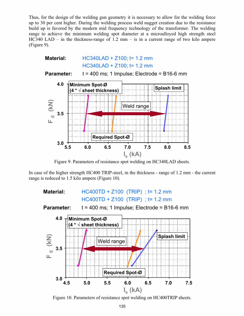
Thus, for the design of the welding gun geometry it is necessary to allow for the welding force up to 30 per cent higher. During the welding process weld nugget creation due to the resistance build up is favored by the modern mid frequency technology of the transformer. The welding range to achieve the minimum welding spot diameter at a microalloyed high strength steel HC340 LAD – in the thickness-range of 1.2 mm – is in a current range of two kilo ampere (Figure 9).
Material: HC340LAD + Z100; t= 1.2 mmHC340LAD + Z100; t= 1.2 mm
Weld range
Minimum Spot-Ø(4 * sheet thickness)
Required Spot-Ø
Splash limit
5.5 6.0 6.5 7.0 7.5 8.0 8.5Is (kA)
4.0
3.5
3.0
FE
(kN
)
Parameter: t = 400 ms; 1 Impulse; Electrode = B16-6 mm
Figure 9. Parameters of resistance spot welding on HC340LAD sheets.
In case of the higher strength HC400 TRIP-steel, in the thickness - range of 1.2 mm - the current range is reduced to 1.5 kilo ampere (Figure 10).
Material: HC400TD + Z100 (TRIP) ; t= 1.2 mmHC400TD + Z100 (TRIP) ; t= 1.2 mm
4.5 5.0 5.5 6.0 6.5 7.0 7.5Is (kA)
4.0
3.5
3.0
FE
(kN
)
Parameter: t = 400 ms; 1 Impulse; Electrode = B16-6 mm
Required Spot-Ø
Minimum Spot-Ø(4 * sheet thickness)
Splash limitWeld range
Figure 10. Parameters of resistance spot welding on HC400TRIP sheets.
135

This means that the process period will become smaller with increasing strength. The welding process reacts more sensitive to disturbances. For compensation and process stabilization purposes, BMW applies an online control at the indicated critical welding tasks (Figure 11).
sputter
Current I (A)Voltage U (V)
Resistance R ( )Power P (W)
Current I
Voltage U
RR
Inugget o.K..
Screenshot Screenshot
principal sketch: IQR
U
P
Figure 11. Resistance spot welding online quality control: Process Stabilization by Intelligent Active Online Process Regulation (IQR).
This control actively influences the process settings and controls the welding process in the target corridor for the safe achievement of the required weld spot diameter. Another issue is the risk of material hardness increase in the range of the joining zone and HAZ. At mixed connection, as indicated in the Figure 12, the varying heat conduction of the individual materials may lead to a movement of the weld nugget (position of the resistance heating). This applies to TRIP-steel as shown in Figure 12.
Material: HC400T + Z100 t= 1.9 mmHC300B + ZE75/75 t=1.6 mm
Hardening at the TRIP metallurgical notchesWeld nugget moves more into the TRIP steel, caused by thelower heat conductivity
TRIP-Steel
BH-Steel
Figure 12. Resistance spot welding: Varying heat conduction on a mixed joint.
136
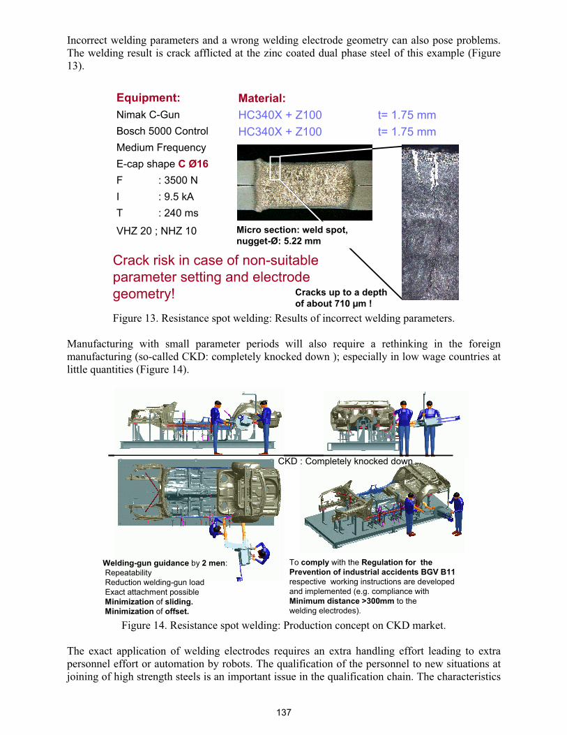
Incorrect welding parameters and a wrong welding electrode geometry can also pose problems. The welding result is crack afflicted at the zinc coated dual phase steel of this example (Figure 13).
Equipment:Nimak C-GunBosch 5000 ControlMedium Frequency E-cap shape C Ø16F : 3500 N I : 9.5 kA T : 240 ms
VHZ 20 ; NHZ 10
Material:HC340X + Z100 t= 1.75 mmHC340X + Z100 t= 1.75 mm
Cracks up to a depth of about 710 μm !
Micro section: weld spot, nugget-Ø: 5.22 mm
Crack risk in case of non-suitableparameter setting and electrode geometry!
Figure 13. Resistance spot welding: Results of incorrect welding parameters.
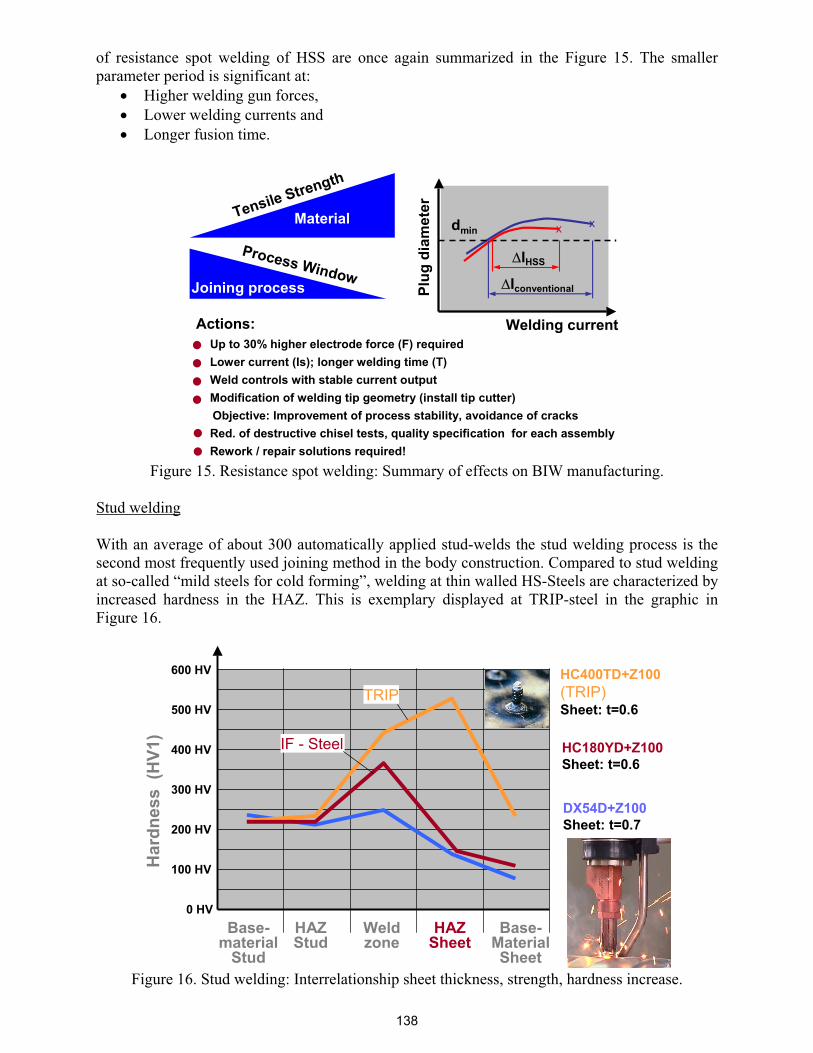
Manufacturing with small parameter periods will also require a rethinking in the foreign manufacturing (so-called CKD: completely knocked down ); especially in low wage countries at little quantities (Figure 14).
CKD : Completely knocked down
Welding-gun guidance by 2 men:RepeatabilityReduction welding-gun loadExact attachment possibleMinimization of sliding.Minimization of offset.
To comply with the Regulation for the Prevention of industrial accidents BGV B11respective working instructions are developedand implemented (e.g. compliance with Minimum distance >300mm to the welding electrodes).
Figure 14. Resistance spot welding: Production concept on CKD market.
The exact application of welding electrodes requires an extra handling effort leading to extra personnel effort or automation by robots. The qualification of the personnel to new situations at joining of high strength steels is an important issue in the qualification chain. The characteristics
137
of resistance spot welding of HSS are once again summarized in the Figure 15. The smaller parameter period is significant at:
Higher welding gun forces, Lower welding currents and Longer fusion time.
Actions:- Up to 30% higher electrode force (F) required- Lower current (Is); longer welding time (T)- Weld controls with stable current output- Modification of welding tip geometry (install tip cutter)
Objective: Improvement of process stability, avoidance of cracks- Red. of destructive chisel tests, quality specification for each assembly- Rework / repair solutions required!
Process Window
Tensile Strength
Iconventional
IHSS
dminx
Welding current
Plug
dia
met
er
xMaterial
Joining process
Figure 15. Resistance spot welding: Summary of effects on BIW manufacturing.
Stud welding
With an average of about 300 automatically applied stud-welds the stud welding process is the second most frequently used joining method in the body construction. Compared to stud welding at so-called “mild steels for cold forming”, welding at thin walled HS-Steels are characterized by increased hardness in the HAZ. This is exemplary displayed at TRIP-steel in the graphic in Figure 16.
0 HV
100 HV
200 HV
300 HV
400 HV
500 HV
600 HV
Har
dnes
s (H
V1)
Base-material
Stud
HAZStud
Weldzone
HAZSheet
Base-MaterialSheet
DX54D+Z100Sheet: t=0.7
HC180YD+Z100Sheet: t=0.6
HC400TD+Z100(TRIP)Sheet: t=0.6
TRIP
IF - Steel
Figure 16. Stud welding: Interrelationship sheet thickness, strength, hardness increase.
138

In general at stud welding of HS-Steel a trend towards: shorter fusion times and higher welding currents can be recognized. This is illustrated exemplary with the DX56 compared to the H400 Steel material (Figure 17). For a better control of a heat input, alternatives in the stud design, for example the “wide flange stud” (see picture on left side in Figure 17) and process variants like “ stud welding with moved magnetic arc ” are processed.
Trend: Shorter welding time with higher current.Capacity of the power source has to be adapted to these requirements min. 1500A
0.7mm DX56+Z100 700A / 30ms0.7mm H400+Z100 1200A / 14ms
Minimum sheet thickness:0.7mm (GS 96005-1)
Alternatives to the series- stud:Magnet arc stud weldingWide flange stud (WFS)
Weld task: WFS on H400TD + Z100 (TRIP)Material-Thickness : 0.7 mmParameter: : 1700A /18msTorque (Mw-3s) : 6.46 NmTensile test (Mw-3s) : 2405 N
Example
new
new
Figure 17. Stud welding: Peculiarities, consequences, further development.
Arc- welding and brazing
Electric arc welding is still an important representative process in the joining technology range of car manufacturing (Figure 18).
- Material problems- Problems on arc welding /brazing- Effects in BIW production
Figure 18. Arc welding / brazing of High-Strength Steel.
139
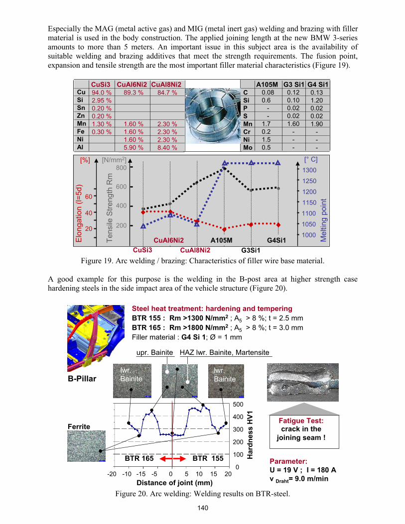
Especially the MAG (metal active gas) and MIG (metal inert gas) welding and brazing with filler material is used in the body construction. The applied joining length at the new BMW 3-series amounts to more than 5 meters. An important issue in this subject area is the availability of suitable welding and brazing additives that meet the strength requirements. The fusion point, expansion and tensile strength are the most important filler material characteristics (Figure 19).
CuSi3 CuAl6Ni2 CuAl8Ni2CuSiSnZnMnFeNiAl
84.7 %
2.30 %2.30 %2.30 %8.40 %
94.0 %2.95 %0.20 %0.20 %1.30 %0.30 %
89.3 %
1.60 %1.60 %1.60 %5.90 %
CuSi3 CuAl8Ni2
200
400
600
[N/mm2]
Tens
ile S
treng
th R
m
Mel
ting
poin
t
[° C]
1000
1050
1100
Elon
gatio
n (l=
5d)
[%]
40
20
60
A105M G3 Si1 G4 Si1CSiPSMnCrNiMo
0.120.100.020.021.60
---
0.080.6
--
1.70.21.50.5
0.131.200.020.021.90
---
CuAl6Ni2G3Si1
A105M G4Si1
800
1150
1200
1250
1300
Figure 19. Arc welding / brazing: Characteristics of filler wire base material.
A good example for this purpose is the welding in the B-post area at higher strength case hardening steels in the side impact area of the vehicle structure (Figure 20).
B-Pillar
Steel heat treatment: hardening and temperingBTR 155 : Rm >1300 N/mm2 ; A5 > 8 %; t = 2.5 mmBTR 165 : Rm >1800 N/mm2 ; A5 > 8 %; t = 3.0 mmFiller material : G4 Si 1; Ø = 1 mm
Parameter:U = 19 V ; I = 180 Av Draht= 9.0 m/min
Fatigue Test:crack in the
joining seam !Ferrite
lwr. Bainite
upr. Bainite
500
400
300
200
100
00 105 15 20-15-20 -10 -5
Har
dnes
s H
V1
BTR 155BTR 165
Distance of joint (mm)
HAZ lwr. Bainite, Martensite
lwr. Bainite
Figure 20. Arc welding: Welding results on BTR-steel.
140
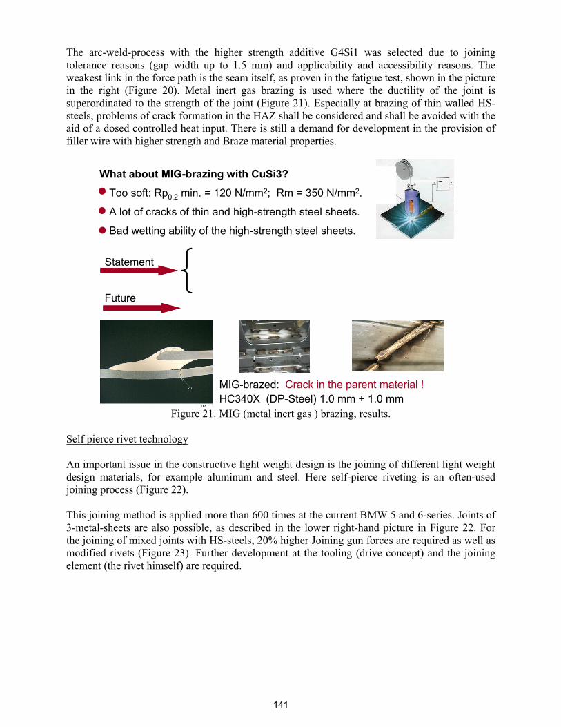
The arc-weld-process with the higher strength additive G4Si1 was selected due to joining tolerance reasons (gap width up to 1.5 mm) and applicability and accessibility reasons. The weakest link in the force path is the seam itself, as proven in the fatigue test, shown in the picture in the right (Figure 20). Metal inert gas brazing is used where the ductility of the joint is superordinated to the strength of the joint (Figure 21). Especially at brazing of thin walled HS-steels, problems of crack formation in the HAZ shall be considered and shall be avoided with the aid of a dosed controlled heat input. There is still a demand for development in the provision of filler wire with higher strength and Braze material properties.
MIG-brazed: Crack in the parent material !HC340X (DP-Steel) 1.0 mm + 1.0 mm
What about MIG-brazing with CuSi3?
• Too soft: Rp0,2 min. = 120 N/mm2; Rm = 350 N/mm2.
• A lot of cracks of thin and high-strength steel sheets.
• Bad wetting ability of the high-strength steel sheets.
Future
Statement
Figure 21. MIG (metal inert gas ) brazing, results.
Self pierce rivet technology
An important issue in the constructive light weight design is the joining of different light weight design materials, for example aluminum and steel. Here self-pierce riveting is an often-used joining process (Figure 22).
This joining method is applied more than 600 times at the current BMW 5 and 6-series. Joints of 3-metal-sheets are also possible, as described in the lower right-hand picture in Figure 22. For the joining of mixed joints with HS-steels, 20% higher Joining gun forces are required as well as modified rivets (Figure 23). Further development at the tooling (drive concept) and the joining element (the rivet himself) are required.
141
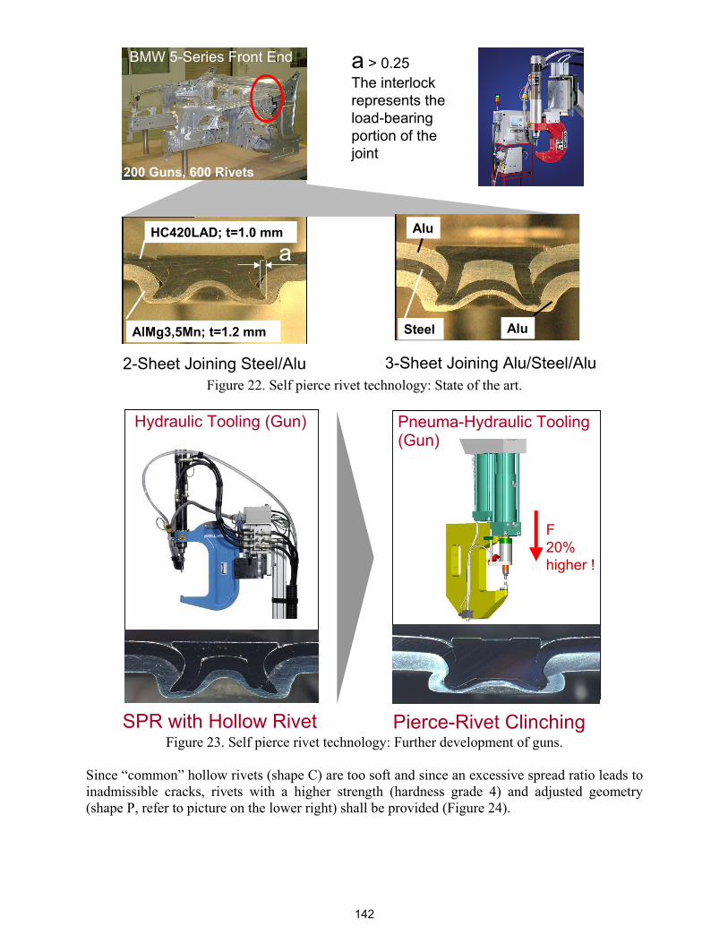
BMW 5-Series Front End
2-Sheet Joining Steel/Alu 3-Sheet Joining Alu/Steel/Alu
AluHC420LAD; t=1.0 mm
AlMg3,5Mn; t=1.2 mm Steel Alu
a
a > 0.25 The interlockrepresents theload-bearingportion of the joint
200 Guns, 600 Rivets
Figure 22. Self pierce rivet technology: State of the art.
Pierce-Rivet Clinching
Pneuma-Hydraulic Tooling (Gun)
Hydraulic Tooling (Gun)
SPR with Hollow Rivet
F20%higher !
Figure 23. Self pierce rivet technology: Further development of guns.
Since “common” hollow rivets (shape C) are too soft and since an excessive spread ratio leads to inadmissible cracks, rivets with a higher strength (hardness grade 4) and adjusted geometry (shape P, refer to picture on the lower right) shall be provided (Figure 24).
142
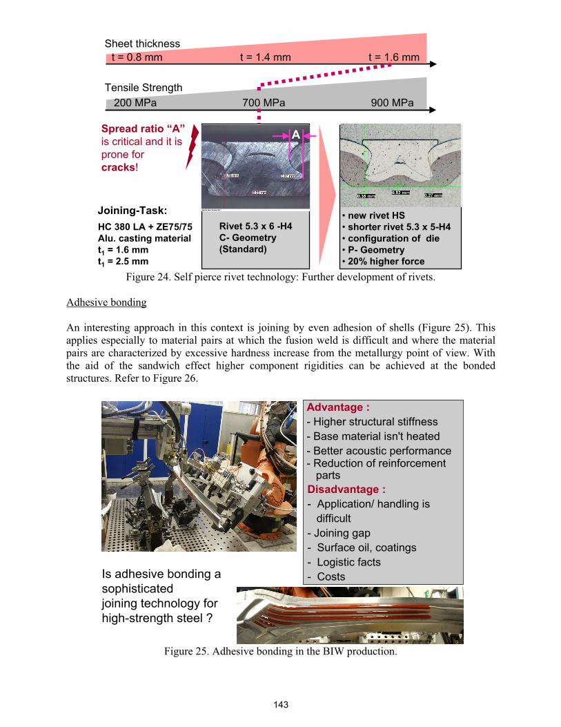
Sheet thickness
200 MPa 700 MPa 900 MPa
t = 0.8 mm t = 1.4 mm t = 1.6 mm
Tensile Strength
ASpread ratio “A”is critical and it is prone forcracks!
HC 380 LA + ZE75/75 Alu. casting material t1 = 1.6 mmt1 = 2.5 mm
Joining-Task: • new rivet HS • shorter rivet 5.3 x 5-H4• configuration of die• P- Geometry• 20% higher force
Rivet 5.3 x 6 -H4C- Geometry (Standard)
Figure 24. Self pierce rivet technology: Further development of rivets.
Adhesive bonding
An interesting approach in this context is joining by even adhesion of shells (Figure 25). This applies especially to material pairs at which the fusion weld is difficult and where the material pairs are characterized by excessive hardness increase from the metallurgy point of view. With the aid of the sandwich effect higher component rigidities can be achieved at the bonded structures. Refer to Figure 26.
Is adhesive bonding asophisticatedjoining technology forhigh-strength steel ?
Advantage :- Higher structural stiffness- Base material isn't heated- Better acoustic performance- Reduction of reinforcement
partsDisadvantage :- Application/ handling is
difficult- Joining gap- Surface oil, coatings- Logistic facts- Costs
Figure 25. Adhesive bonding in the BIW production.
143

Forc
e
Deformation way
conventional energyconsumption
Higher stiffness:bonded structure
Figure 26. Adhesive bonding: Increasing rigidity of bonded structures.
In addition to those advantages the bonding technology is characterized by a certain complexness in the application technique. The requirements upon bonded gaps of up to few tenths of a millimeter have to be managed from the component-side. The adhesion behavior of adhesives – at coated steel sheets – is a constantly to be verified question. In addition to a controlled logistics – in the sense of adhesive open periods of the adhesive box – the relatively high costs for adhesives at the planned applications shall also be observed.
Laser beam welding and brazing
Laser-beam-welding and brazing are more and more used in the car manufacturing. Narrow weld seams, fast process speeds and a one-way accessibility only to the joining task are impressive reasons for this process (Figure 27). As heat source gas- (CO2), solid-state- and brand new the disk-laser, with a power range of 2000 to 8000 W are applied.
CO2-Laser
Power range : 2000 – 8000 Watt
Used for applications:welding, cutting
Solid-State Laser(Nd: YAG-Laser )Power range : 3000 – 4000 Watt
Used for applications:welding, brazing
process
processFigure 27. Laser beam joining of high strength steel.
Due to the small, but very concentrated heat application (low heat input per unit length of the weld) the hardness increase behavior at the different material pairs especially at HS-Steels shall be observed (Figure 28). The degree of hardness of up to and above 500 degree Vickers may strongly influence the ductility of the joint.
144

Material: SD800C ( CP) ; t= 3.0 mmHC800T (TRIP) ; t= 2.0 mm
Material: HC420LAD Z100 ; t= 1.2 mmHC800T (TRIP) ; t=2.0 mm
Laser powerProgress speedRoll pressureFocus positionFocal lengthShield gas
Laser powerProgress speedRoll pressureFocus positionFocal lengthShield gas
Figure 28. Laser beam welding: Examples of cross sections on HSS.
In a sponsored research project the pre heating effect by means of inductive preheating at TRIP- steels was investigated. With a preheating inductor performance of 14 kW a reduction of hardness increase in the weld seam and basic material can be achieved, as shown in the graphic on the right page (Figure 29). This effect was proven at further material pairs with different Carbon Equivalents (CE). The results are shown in Figure 30. How far preheating in practice is feasible, considering the space critical considerations at 3-dimensional components shall be verified from case to case.
Cover sheet : HC400T +Z; 1.5mmGap : 0.2 mmLower sheet . HC400T +Z; 1.5 mmLaser power : 400 WattWelding speed : 3.5 m/min
Material + parameter as left side
Inductor power : 14 kWDistance/gap : 1.5 mmWelding speed : 4.2 m/min
HC 400T+ZHC 400T+Z Adjustment
Line inductor
Laser head
Clampingdevice
Figure 29. Laser beam welding: Preheating effects on weld metal.
145
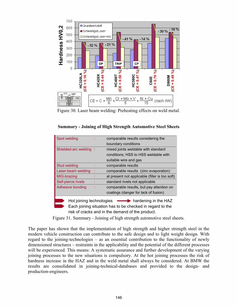
HC
420X
(CE
= 0.
44 %
)
HC
320L
A(C
E =
0.16
%)
HC
400T
(CE
= 0.
50 %
)
HC
580C
(CE
= 0.
47 %
)
C60
E(C
E =
0.70
%)
D90
0M(C
E =
0.49
%)
Har
dnes
s H
V0,2
DP TRIP CP
Figure 30. Laser beam welding: Preheating effects on weld metal.
Summary - Joining of High Strength Automotive Steel Sheets
Spot welding : comparable results considering the boundary conditions
Shielded-arc welding : mixed joints weldable with standard conditions; HSS to HSS weldable with suitable wire and gas
Stud welding : comparable resultsLaser-beam welding : comparable results (zinc evaporation)MIG-brazing : at present not applicable (filler is too soft)Self-pierce rivets : standard rivets not applicableAdhesive bonding : comparable results, but pay attention on
coatings (danger for lack of fusion)
Hot joining technologies hardening in the HAZEach joining situation has to be checked in regard to therisk of cracks and in the demand of the product.
Figure 31. Summary - Joining of high strength automotive steel sheets.
The paper has shown that the implementation of high strength and higher strength steel in the modern vehicle construction can contribute to the safe design and to light weight design. With regard to the joining-technologies – as an essential contribution to the functionality of newly dimensioned structures – restraints in the applicability and the potential of the different processes will be experienced. This means: A systematic assurance and further development of the varying joining processes to the new situations is compulsory. At the hot joining processes the risk of hardness increase in the HAZ and in the weld metal shall always be considered. At BMW the results are consolidated in joining-technical-databases and provided to the design- and production-engineers.
146


