Manufacturer reserves the right to discontinue, or change at any time, specifications or designs without notice and without incurring obligations.Catalog No. 04-53230002-01 Printed in U.S.A. Form 23XRV-2SI Pg 1 2-11 Replaces: 23XRV-1SI
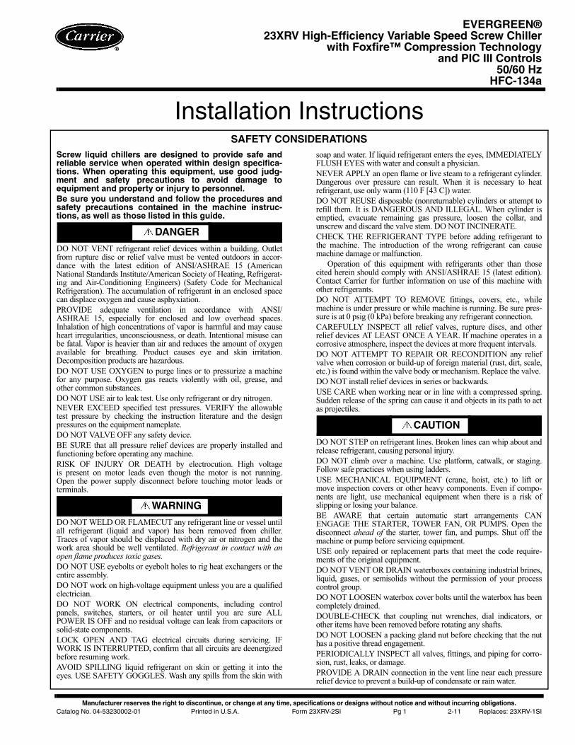
Installation InstructionsSAFETY CONSIDERATIONS
Screw liquid chillers are designed to provide safe andreliable service when operated within design specifica-tions. When operating this equipment, use good judg-ment and safety precautions to avoid damage toequipment and property or injury to personnel.Be sure you understand and follow the procedures andsafety precautions contained in the machine instruc-tions, as well as those listed in this guide.
DO NOT VENT refrigerant relief devices within a building. Outletfrom rupture disc or relief valve must be vented outdoors in accor-dance with the latest edition of ANSI/ASHRAE 15 (AmericanNational Standards Institute/American Society of Heating, Refrigerat-ing and Air-Conditioning Engineers) (Safety Code for MechanicalRefrigeration). The accumulation of refrigerant in an enclosed spacecan displace oxygen and cause asphyxiation.PROVIDE adequate ventilation in accordance with ANSI/ASHRAE 15, especially for enclosed and low overhead spaces.Inhalation of high concentrations of vapor is harmful and may causeheart irregularities, unconsciousness, or death. Intentional misuse canbe fatal. Vapor is heavier than air and reduces the amount of oxygenavailable for breathing. Product causes eye and skin irritation.Decomposition products are hazardous.DO NOT USE OXYGEN to purge lines or to pressurize a machinefor any purpose. Oxygen gas reacts violently with oil, grease, andother common substances.DO NOT USE air to leak test. Use only refrigerant or dry nitrogen.NEVER EXCEED specified test pressures. VERIFY the allowabletest pressure by checking the instruction literature and the designpressures on the equipment nameplate.DO NOT VALVE OFF any safety device.BE SURE that all pressure relief devices are properly installed andfunctioning before operating any machine.RISK OF INJURY OR DEATH by electrocution. High voltageis present on motor leads even though the motor is not running.Open the power supply disconnect before touching motor leads orterminals.
DO NOT WELD OR FLAMECUT any refrigerant line or vessel untilall refrigerant (liquid and vapor) has been removed from chiller.Traces of vapor should be displaced with dry air or nitrogen and thework area should be well ventilated. Refrigerant in contact with anopen flame produces toxic gases.DO NOT USE eyebolts or eyebolt holes to rig heat exchangers or theentire assembly.DO NOT work on high-voltage equipment unless you are a qualifiedelectrician.DO NOT WORK ON electrical components, including controlpanels, switches, starters, or oil heater until you are sure ALLPOWER IS OFF and no residual voltage can leak from capacitors orsolid-state components.LOCK OPEN AND TAG electrical circuits during servicing. IFWORK IS INTERRUPTED, confirm that all circuits are deenergizedbefore resuming work.AVOID SPILLING liquid refrigerant on skin or getting it into theeyes. USE SAFETY GOGGLES. Wash any spills from the skin with
soap and water. If liquid refrigerant enters the eyes, IMMEDIATELYFLUSH EYES with water and consult a physician.NEVER APPLY an open flame or live steam to a refrigerant cylinder.Dangerous over pressure can result. When it is necessary to heatrefrigerant, use only warm (110 F [43 C]) water.DO NOT REUSE disposable (nonreturnable) cylinders or attempt torefill them. It is DANGEROUS AND ILLEGAL. When cylinder isemptied, evacuate remaining gas pressure, loosen the collar, andunscrew and discard the valve stem. DO NOT INCINERATE.CHECK THE REFRIGERANT TYPE before adding refrigerant tothe machine. The introduction of the wrong refrigerant can causemachine damage or malfunction.
Operation of this equipment with refrigerants other than thosecited herein should comply with ANSI/ASHRAE 15 (latest edition).Contact Carrier for further information on use of this machine withother refrigerants.DO NOT ATTEMPT TO REMOVE fittings, covers, etc., whilemachine is under pressure or while machine is running. Be sure pres-sure is at 0 psig (0 kPa) before breaking any refrigerant connection.CAREFULLY INSPECT all relief valves, rupture discs, and otherrelief devices AT LEAST ONCE A YEAR. If machine operates in acorrosive atmosphere, inspect the devices at more frequent intervals.DO NOT ATTEMPT TO REPAIR OR RECONDITION any reliefvalve when corrosion or build-up of foreign material (rust, dirt, scale,etc.) is found within the valve body or mechanism. Replace the valve.DO NOT install relief devices in series or backwards.USE CARE when working near or in line with a compressed spring.Sudden release of the spring can cause it and objects in its path to actas projectiles.
DO NOT STEP on refrigerant lines. Broken lines can whip about andrelease refrigerant, causing personal injury.DO NOT climb over a machine. Use platform, catwalk, or staging.Follow safe practices when using ladders.USE MECHANICAL EQUIPMENT (crane, hoist, etc.) to lift ormove inspection covers or other heavy components. Even if compo-nents are light, use mechanical equipment when there is a risk ofslipping or losing your balance.BE AWARE that certain automatic start arrangements CANENGAGE THE STARTER, TOWER FAN, OR PUMPS. Open thedisconnect ahead of the starter, tower fan, and pumps. Shut off themachine or pump before servicing equipment.USE only repaired or replacement parts that meet the code require-ments of the original equipment.DO NOT VENT OR DRAIN waterboxes containing industrial brines,liquid, gases, or semisolids without the permission of your processcontrol group.DO NOT LOOSEN waterbox cover bolts until the waterbox has beencompletely drained.DOUBLE-CHECK that coupling nut wrenches, dial indicators, orother items have been removed before rotating any shafts.DO NOT LOOSEN a packing gland nut before checking that the nuthas a positive thread engagement.PERIODICALLY INSPECT all valves, fittings, and piping for corro-sion, rust, leaks, or damage.PROVIDE A DRAIN connection in the vent line near each pressurerelief device to prevent a build-up of condensate or rain water.
DANGER
WARNING
CAUTION
EVERGREEN®23XRV High-Efficiency Variable Speed Screw Chiller
with Foxfire™ Compression Technologyand PIC III Controls
50/60 HzHFC-134a

2
CONTENTSPage
SAFETY CONSIDERATIONS . . . . . . . . . . . . . . . . . . . . . . 1INTRODUCTION . . . . . . . . . . . . . . . . . . . . . . . . . . . . . . . . . . 2General. . . . . . . . . . . . . . . . . . . . . . . . . . . . . . . . . . . . . . . . . . . 2Job Data. . . . . . . . . . . . . . . . . . . . . . . . . . . . . . . . . . . . . . . . . . 2INSTALLATION . . . . . . . . . . . . . . . . . . . . . . . . . . . . . . . . 2-42Step 1 — Receive the Machine . . . . . . . . . . . . . . . . . . 2• INSPECT SHIPMENT• IDENTIFY MACHINE• INSTALLATION REQUIREMENTS• PROVIDE MACHINE PROTECTIONStep 2 — Rig the Machine . . . . . . . . . . . . . . . . . . . . . . . 3• RIG MACHINE ASSEMBLY• RIG MACHINE COMPONENTSStep 3 — Separate Machine Components . . . . . . 13• SEPARATE COOLER AND CONDENSER• REMOVE THE CONTROLS/DRIVE ENCLOSURE
FROM THE CONDENSER• REMOVE THE DISCHARGE PIPE ASSEMBLY
FROM THE CONDENSER• SEPARATE THE COMPRESSOR FROM THE
CONDENSER• SEPARATE THE VAPORIZER FROM THE
CONDENSERStep 4 — Install VFD. . . . . . . . . . . . . . . . . . . . . . . . . . . . 19Step 5 — Install Machine Supports . . . . . . . . . . . . . 22• INSTALL STANDARD ISOLATION• INSTALL ACCESSORY ISOLATION• INSTALL SPRING ISOLATIONStep 6 — Connect Piping . . . . . . . . . . . . . . . . . . . . . . . 24• INSTALL WATER PIPING TO HEAT
EXCHANGERS• INSTALL VENT PIPING TO RELIEF VALVESStep 7 — Make Electrical Connections . . . . . . . . . 30• GROUNDING THE CONTROLS/DRIVE
ENCLOSURE• INSTALLING INPUT POWER WIRING• WIRING THE FIELD WIRING TERMINAL STRIPS• CONNECT CONTROL INPUTS• CONNECT CONTROL OUTPUTS• CONNECT STARTERCOMPLETING THE INSTALLATION . . . . . . . . . . . 43-50Checking the Installation . . . . . . . . . . . . . . . . . . . . . . . . 43Oil Pump and Oil Heater . . . . . . . . . . . . . . . . . . . . . . . . . 43Connect Control Wiring . . . . . . . . . . . . . . . . . . . . . . . . . 43Carrier Comfort Network® Interface . . . . . . . . . . . . . 43Optional BACnet Communications Wiring . . . . . . . 44Lead-Lag Control Wiring . . . . . . . . . . . . . . . . . . . . . . . . 44Install Field Insulation . . . . . . . . . . . . . . . . . . . . . . . . . . . 44INSTALLATION START-UP REQUEST
CHECKLIST . . . . . . . . . . . . . . . . . . . . . . . . . . . CL-1, CL-2
INTRODUCTION
General — The 23XRV machine is factory assembled,wired, and leak tested. Installation (not by Carrier) consistsprimarily of establishing water and electrical services to themachine. The rigging, installation, field wiring, field piping,and insulation of waterbox covers are the responsibility of thecontractor and/or customer. Carrier has no installation respon-sibilities for the equipment.
Job Data — Necessary information consists of:• job contract or specifications• machine location prints• rigging information• piping prints and details• field wiring drawings• starter manufacturer’s installation details• Carrier certified print
INSTALLATION
Step 1 — Receive the MachineINSPECT SHIPMENT
1. Inspect for shipping damage while machine is still on ship-ping conveyance. If machine appears to be damaged orhas been torn loose from its anchorage, have it examinedby transportation inspectors before removal. Forwardclaim papers directly to transportation company. Manufac-turer is not responsible for any damage incurred in transit.
2. Check all items against shipping list. Immediately notifythe nearest Carrier representative if any item is missing.
3. To prevent loss or damage, leave all parts in original pack-ages until beginning installation. All openings are closedwith covers or plugs to prevent dirt and debris from enter-ing machine components during shipping. A full operatingoil charge is placed in the oil sump before shipment.
IDENTIFY MACHINE (Fig. 1-4) — Refer to machine name-plate in Fig. 1. The machine model number, serial number, andheat exchanger sizes are stamped on the Refrigeration Machinenameplate located on the side of the VFD (variable frequencydrive) enclosure. Check this information against shippingpapers and job data.
CAUTION
Do not open any valves or loosen any connections. The23XRV machine may be shipped with a full refrigerantcharge. Some machines may be shipped with a nitrogenholding charge as an option.
Fig. 1 — Refrigeration Machine Nameplate
a23-1547

3
Identifying Drive by Part Number — Each LiquiFlo™ 2.0AC drive can be identified by its part number. See Fig. 5. Thisnumber appears on the shipping label and on VFD nameplate.Drive Input Component Location — Figure 6 identifies thecontrol center components.Identifying Power Module by ID Number — Each LiquiFlo 2.0AC power module can be identified by its ID number. See Fig. 5.This number appears on the shipping label and on the powermodule’s nameplate. Power ratings are provided in Table 1.ISTALLATION REQUIREMENTS — Certain installationrequirements should be checked before continuing with thechiller’s electrical installation. Input power wire sizes, branchcircuit protection, and control wiring are all areas that need tobe evaluated.Determining Wire Size Requirements — Wire size should bedetermined based on the size of the conduit openings, andapplicable local, national, and international codes (e.g., NEC[National Electric Code]/CEC [California Energy Commis-sion] regulations). General recommendations are included inthe Carrier field wiring drawing.Conduit Entry Size — It is important to determine the size ofthe conduit openings in the enclosure power entry plate so thatthe wire planned for a specific entry point will fit through theopening. Do NOT punch holes or drill into the top surface ofthe control center enclosure for field wiring. Do not punchholes or drill into the top surface of the control center enclosurefor field wiring. Knockouts are provided in the back of thecontrol center for field control wiring connections.Recommended Control and Signal Wire Sizes — The rec-ommended minimum size wire to connect I/O signals to thecontrol terminal blocks is 18 AWG (American Wire Gage).Recommended terminal tightening torque is 7 to 9 in.-lb(0.79 to 1.02 N-m).
Recommended Airflow Clearances — Be sure there is ade-quate clearance for air circulation around the enclosure.A 6-in. (152.4 mm) minimum clearance is required wherevervents are located in the VFD enclosure.Match Power Module Input and Supply Power Ratings — Itis important to verify that building power will meet the inputpower requirements of the Machine Electrical Data nameplateinput power rating. Be sure the input power to the chillercorresponds to the chiller’s nameplate voltage, current, andfrequency. Refer to machine nameplate in Fig. 7. The machineelectrical data nameplate is located on the right side of thecontrol center.PROVIDE MACHINE PROTECTION — Protect machineand VFD enclosure from construction dirt and moisture. Keepprotective shipping covers in place until machine is ready forinstallation.
If machine is exposed to freezing temperatures after watercircuits have been installed, open waterbox drains and removeall water from cooler and condenser. Leave drains open untilsystem is filled.
It is important to properly plan before installing a 23XRVunit to ensure that the environment and operating conditionsare satisfactory. The installation must comply with all require-ments in the certified prints.
Chiller should be installed in an indoor environment wherethe ambient temperature is between 40 and 104 F (4 and 40 C)with relative humidity of 95% or less.
Step 2 — Rig the Machine — The 23XRV machinecan be rigged as an entire assembly. Large interconnecting pip-ing has flanged connections that allow the compressor, cooler,and condenser sections to be separated and rigged individually.In addition, the VFD can be removed and rigged separately.
23XRV – High EfficiencyVariable Speed Screw Chiller
Cooler Size*30-3235-3740-4245-4750-5255-57
Condenser Size* 30-3235-3740-4245-4750-5255-57
Economizer OptionE – With EconomizerN – No Economizer
S – Special
R – Compressor
Not Used
Voltage Code3 – 380-3-604 – 416-3-605 – 460-3-609 – 400-3-50
DriveFrame AA BA BB CC
Rectifier MaxInput Amps†440520520608
Inverter MaxOutput Amps†442442520608
Motor CodePQRSTUV
Max Motor Amps265283306334368421440
Fig. 2 — Model Number Identification
a23-1533*First number denotes frame size.†Maximum limits only. Additional application limits apply that may reduce these ampacities.
4
20
19
18 1716
1514
1312
1110
9
8
7
6
5
4321
21
222324
25
26
27
28
293032 3133
35 343637
38394041
50
49
48
47
46
45
51
444342
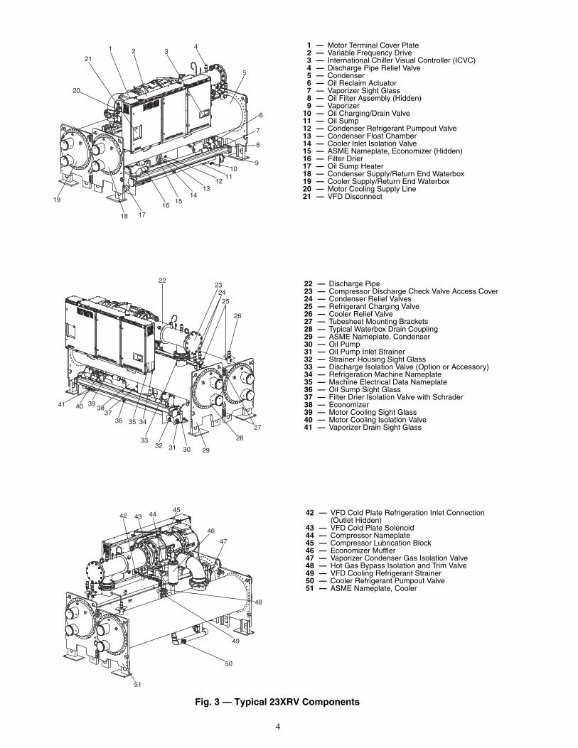
1 — Motor Terminal Cover Plate2 — Variable Frequency Drive3 — International Chiller Visual Controller (ICVC)4 — Discharge Pipe Relief Valve5 — Condenser6 — Oil Reclaim Actuator7 — Vaporizer Sight Glass8 — Oil Filter Assembly (Hidden)9 — Vaporizer
10 — Oil Charging/Drain Valve11 — Oil Sump12 — Condenser Refrigerant Pumpout Valve13 — Condenser Float Chamber14 — Cooler Inlet Isolation Valve15 — ASME Nameplate, Economizer (Hidden)16 — Filter Drier17 — Oil Sump Heater18 — Condenser Supply/Return End Waterbox19 — Cooler Supply/Return End Waterbox20 — Motor Cooling Supply Line21 — VFD Disconnect
22 — Discharge Pipe23 — Compressor Discharge Check Valve Access Cover24 — Condenser Relief Valves25 — Refrigerant Charging Valve26 — Cooler Relief Valve27 — Tubesheet Mounting Brackets28 — Typical Waterbox Drain Coupling29 — ASME Nameplate, Condenser30 — Oil Pump31 — Oil Pump Inlet Strainer32 — Strainer Housing Sight Glass33 — Discharge Isolation Valve (Option or Accessory)34 — Refrigeration Machine Nameplate35 — Machine Electrical Data Nameplate36 — Oil Sump Sight Glass37 — Filter Drier Isolation Valve with Schrader38 — Economizer39 — Motor Cooling Sight Glass40 — Motor Cooling Isolation Valve41 — Vaporizer Drain Sight Glass
42 — VFD Cold Plate Refrigeration Inlet Connection (Outlet Hidden)
43 — VFD Cold Plate Solenoid44 — Compressor Nameplate45 — Compressor Lubrication Block46 — Economizer Muffler47 — Vaporizer Condenser Gas Isolation Valve48 — Hot Gas Bypass Isolation and Trim Valve49 — VFD Cooling Refrigerant Strainer50 — Cooler Refrigerant Pumpout Valve51 — ASME Nameplate, Cooler
Fig. 3 — Typical 23XRV Components
a23-1548
a23-1549
a23-1550
5
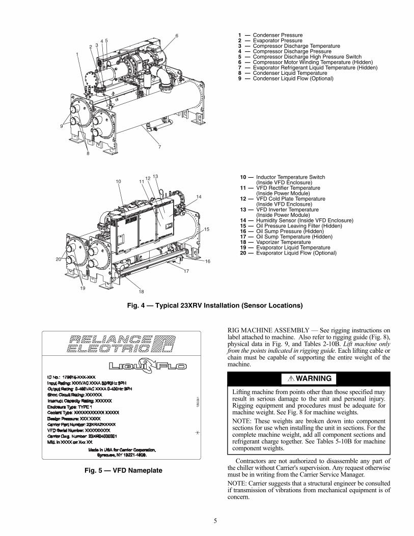
RIG MACHINE ASSEMBLY — See rigging instructions onlabel attached to machine. Also refer to rigging guide (Fig. 8),physical data in Fig. 9, and Tables 2-10B. Lift machine onlyfrom the points indicated in rigging guide. Each lifting cable orchain must be capable of supporting the entire weight of themachine.
Contractors are not authorized to disassemble any part ofthe chiller without Carrier's supervision. Any request otherwisemust be in writing from the Carrier Service Manager.NOTE: Carrier suggests that a structural engineer be consultedif transmission of vibrations from mechanical equipment is ofconcern.
7
64
2
1
35
8
9
1918
17
16
15
14
111012 13
20
Fig. 4 — Typical 23XRV Installation (Sensor Locations)
1 — Condenser Pressure2 — Evaporator Pressure3 — Compressor Discharge Temperature4 — Compressor Discharge Pressure5 — Compressor Discharge High Pressure Switch6 — Compressor Motor Winding Temperature (Hidden)7 — Evaporator Refrigerant Liquid Temperature (Hidden)8 — Condenser Liquid Temperature9 — Condenser Liquid Flow (Optional)
10 — Inductor Temperature Switch (Inside VFD Enclosure)
11 — VFD Rectifier Temperature (Inside Power Module)
12 — VFD Cold Plate Temperature (Inside VFD Enclosure)
13 — VFD Inverter Temperature (Inside Power Module)
14 — Humidity Sensor (Inside VFD Enclosure)15 — Oil Pressure Leaving Filter (Hidden)16 — Oil Sump Pressure (Hidden)17 — Oil Sump Temperature (Hidden)18 — Vaporizer Temperature19 — Evaporator Liquid Temperature20 — Evaporator Liquid Flow (Optional)
a23-1551
a23-1552
Fig. 5 — VFD Nameplate
a23-1553
WARNING
Lifting machine from points other than those specified mayresult in serious damage to the unit and personal injury.Rigging equipment and procedures must be adequate formachine weight. See Fig. 8 for machine weights.NOTE: These weights are broken down into componentsections for use when installing the unit in sections. For thecomplete machine weight, add all component sections andrefrigerant charge together. See Tables 5-10B for machinecomponent weights.

6
13
65
81
91 0212
23
1412
11119
71
4 61
81
5
87
515
1
01
Fig
. 6 —
Co
ntr
ol C
ente
r C
om
po
nen
ts
1—
Inpu
t Pow
er W
iring
Pan
el12
—P
ower
Mod
ule
Nam
epla
te2
—In
put I
nduc
tor
Ass
embl
y13
—A
C C
onta
ctor
(3)
3—
Cap
acito
r B
ank
Ass
embl
y14
—P
re-C
harg
e R
esis
tor
Ass
embl
y4
—F
use,
Cla
ss C
C, 6
00V,
20A
(3)
15—
Line
Syn
c P
C B
oard
Ass
embl
y5
—F
use
Bla
ck, 3
0A, 6
00V,
Cla
ss C
C16
—Li
ne S
ync
Boa
rd C
over
6—
Tran
sfor
mer
, 3kV
A17
—F
use,
Cla
ss C
C, 6
00V,
1A
(3)
7—
Fus
e, C
lass
CC
, 600
V, 5
A (
1)18
—Fa
n, 1
15V
(2)
8—
Fus
e, C
lass
CC
, 600
V, 1
5A (
2)19
—C
ircui
t Bre
aker
, 600
V, 1
5A9
—P
ower
Mod
ule
Ass
embl
y20
—C
ircui
t Bre
aker
, 600
V10
—C
omm
unic
atio
ns In
terf
ace
Boa
rd21
—Lu
g, G
roun
d, 2
-600
MC
M11
—Te
rmin
al B
lock
, 10-
Pos
ition
(2)
a23-1651
7
CHAIN “B”(SEE NOTE #2)
CHAIN “C”(SEE NOTE #2)
CHAIN “D”(SEE NOTE #2)
15´-0´´ MIN. HEIGHTABOVE FLOOR
“E”
“F”“A”
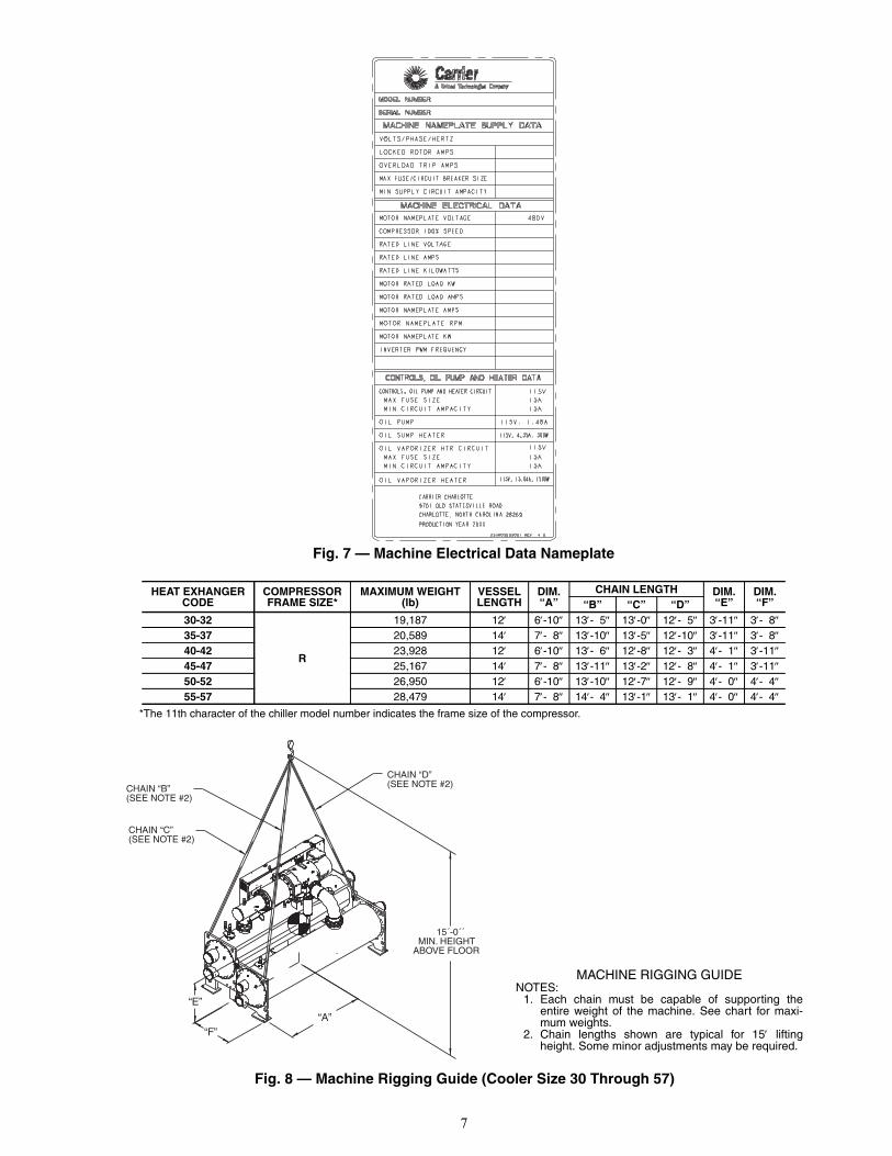
Fig. 7 — Machine Electrical Data Nameplate
*The 11th character of the chiller model number indicates the frame size of the compressor.
HEAT EXHANGER CODE
COMPRESSOR FRAME SIZE*
MAXIMUM WEIGHT (lb)
VESSEL LENGTH
DIM. “A”
CHAIN LENGTH DIM. “E”
DIM. “F”“B” “C” “D”
30-32
R
19,187 12 6-10 13- 5 13-0 12- 5 3-11 3- 835-37 20,589 14 7- 8 13-10 13-5 12-10 3-11 3- 840-42 23,928 12 6-10 13- 6 12-8 12- 3 4- 1 3-1145-47 25,167 14 7- 8 13-11 13-2 12- 8 4- 1 3-1150-52 26,950 12 6-10 13-10 12-7 12- 9 4- 0 4- 455-57 28,479 14 7- 8 14- 4 13-1 13- 1 4- 0 4- 4
MACHINE RIGGING GUIDENOTES:
1. Each chain must be capable of supporting theentire weight of the machine. See chart for maxi-mum weights.
2. Chain lengths shown are typical for 15 liftingheight. Some minor adjustments may be required.
Fig. 8 — Machine Rigging Guide (Cooler Size 30 Through 57)
a23-1555
a23-1556
8
Table 1 — Drive Assembly and Power Module Ratings
*110% output current capability for one minute, 150% output current for 5 seconds.
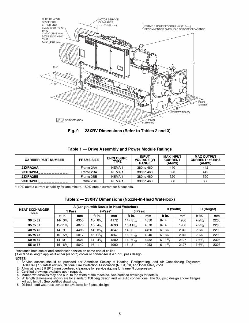
Table 2 — 23XRV Dimensions (Nozzle-In-Head Waterbox)
*Assumes both cooler and condenser nozzles on same end of chiller.†1 or 3 pass length applies if either (or both) cooler or condenser is a 1 or 3 pass design.NOTES:
1. Service access should be provided per American Society of Heating, Refrigerating, and Air Conditioning Engineers(ASHRAE) 15, latest edition, National Fire Protection Association (NFPA) 70, and local safety code.
2. Allow at least 3 ft (915 mm) overhead clearance for service rigging for frame R compressor. 3. Certified drawings available upon request.4. Marine waterboxes may add 6 in. to the width of the machine. See certified drawings for details.5. ‘A’ length dimensions shown are for standard 150 psig design and victaulic connections. The 300 psig design and/or flanges
will add length. See certified drawings.6. Dished head waterbox covers not available for 3 pass design.
CARRIER PART NUMBER FRAME SIZE ENCLOSURE TYPE
INPUT VOLTAGE (V)
RANGE
MAX INPUT CURRENT
(AMPS)
MAX OUTPUT CURRENT* at 4kHZ
(AMPS)23XRA2AA_ _ _ _ _ _ _ _ _ _ _ Frame 2AA NEMA 1 380 to 460 440 44223XRA2BA_ _ _ _ _ _ _ _ _ _ _ Frame 2BA NEMA 1 380 to 460 520 44223XRA2BB_ _ _ _ _ _ _ _ _ _ _ Frame 2BB NEMA 1 380 to 460 520 52023XRA2CC_ _ _ _ _ _ _ _ _ _ _ Frame 2CC NEMA 1 380 to 460 608 608
HEAT EXCHANGERSIZE
A (Length, with Nozzle-in-Head Waterbox)B (Width) C (Height)
1 Pass 2-Pass* 3 Pass†ft-in. mm ft-in. mm ft-in. mm ft-in. mm ft-in. mm
30 to 32 14- 31/4 4350 13- 81/4 4172 14- 31/4 4350 6- 4 1930 7-25/8 2200
35 to 37 15-113/4 4870 15- 43/4 4693 15-113/4 4870 6- 4 1930 7-25/8 2200
40 to 42 14- 9 4496 14- 31/8 4347 14- 6 4420 6- 8½ 2045 7-6½ 2299
45 to 47 16- 51/2 5017 15-115/8 4867 16- 21/2 4940 6- 8½ 2045 7-6½ 2299
50 to 52 14-10 4521 14- 41/2 4382 14- 61/2 4432 6-113/4 2127 7-63/4 2305
55 to 57 16- 61/2 5042 16- 1 4902 16- 3 4953 6-113/4 2127 7-63/4 2305
C
FRAME R COMPRESSOR 3’ - 0” (915mm)RECOMMENDED OVERHEAD SERVICE CLEARANCE
2’ MIN(610 mm)
(WIDEST POINT)
4’ - 10” MIN(1219 mm)
A
MOTOR SERVICECLEARANCE1’ - 10” (559 mm)
TUBE REMOVALSPACE FOREITHER ENDSIZES 30-32, 40-42,50-5212’-7½” (3848 mm)SIZES 35-37, 45-47,55-5714’-4” (4369 mm)
B
4’-10”
0’-3”
0’-3”
0’-5”
SERVICE AREA
Fig. 9 — 23XRV Dimensions (Refer to Tables 2 and 3)
a23-1557
9
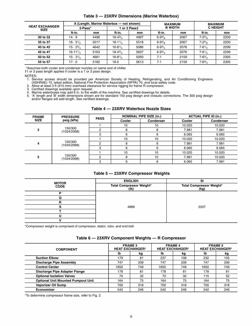
Table 3 — 23XRV Dimensions (Marine Waterbox)
*Assumes both cooler and condenser nozzles on same end of chiller.†1 or 3 pass length applies if cooler is a 1 or 3 pass design.NOTES:
1. Service access should be provided per American Society of Heating, Refrigerating, and Air Conditioning Engineers(ASHRAE) 15, latest edition, National Fire Protection Association (NFPA) 70, and local safety code.
2. Allow at least 3 ft (915 mm) overhead clearance for service rigging for frame R compressor.3. Certified drawings available upon request.4. Marine waterboxes may add 6 in. to the width of the machine. See certified drawings for details.5. ‘A’ length and ‘B’ width dimensions shown are for standard 150 psig design and victaulic connections. The 300 psig design
and/or flanges will add length. See certified drawings.
Table 4 — 23XRV Waterbox Nozzle Sizes
Table 5 — 23XRV Compressor Weights
*Compressor weight is comprised of compressor, stator, rotor, and end bell.
Table 6 — 23XRV Component Weights — R Compressor
*To determine compressor frame size, refer to Fig. 2.
HEAT EXCHANGERSIZE
A (Length, Marine Waterbox — not shown) MAXIMUMB WIDTH
MAXIMUMC HEIGHT2-Pass* 1 or 3 Pass†
ft-in. mm ft-in. mm ft-in. mm ft-in. mm30 to 32 14- 9 4496 16-43/4 4997 6-93/8 2067 7-25/8 2200
35 to 37 16- 51/2 5017 18-11/4 5518 6-93/8 2067 7-25/8 2200
40 to 42 15- 23/4 4642 16-81/4 5086 6-93/4 2076 7-61/2 2299
45 to 47 16-111/4 5163 18-43/4 5607 6-93/4 2076 7-61/2 2299
50 to 52 15- 31/2 4661 16-81/2 5093 7-1 2159 7-63/4 2305
55 to 57 17- 0 5182 18-5 5613 7-1 2159 7-63/4 2305
FRAMESIZE
PRESSUREpsig (kPa) PASS
NOMINAL PIPE SIZE (in.) ACTUAL PIPE ID (in.)Cooler Condenser Cooler Condenser
3 150/300(1034/2068)
1 10 10 10.020 10.0202 8 8 7.981 7.9813 6 6 6.065 6.065
4 150/300(1034/2068)
1 10 10 10.020 10.0202 8 8 7.981 7.9813 6 6 6.065 6.065
5 150/300(1034/2068)
1 10 10 10.020 10.0202 8 10 7.981 10.0203 6 8 6.065 7.981
MOTORCODE
ENGLISH SITotal Compressor Weight*
(lb)Total Compressor Weight*
(kg)P
4866 2207
QRSTUV
COMPONENTFRAME 3
HEAT EXCHANGER*FRAME 4
HEAT EXCHANGER*FRAME 5
HEAT EXCHANGER*lb kg lb kg lb kg
Suction Elbow 179 81 237 108 232 105Discharge Pipe Assembly 747 339 747 339 747 339Control Center 1650 749 1650 749 1650 749Discharge Pipe Adapter Flange 178 81 178 81 178 81Optional Isolation Valves 70 32 70 32 115 52Optional Unit Mounted Pumpout Unit 164 75 164 75 164 75Vaporizer Oil Sump 700 318 700 318 700 318Economizer 542 246 542 246 542 246
10
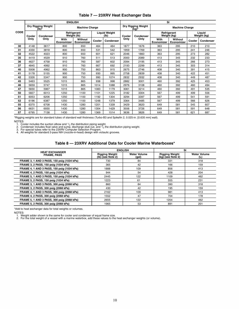
Table 7 — 23XRV Heat Exchanger Data
*Rigging weights are for standard tubes of standard wall thickness (Turbo-B3 and Spikefin 2, 0.025-in. [0.635 mm] wall).NOTES:
1. Cooler includes the suction elbow and 1/2 the distribution piping weight.2. Condenser includes float valve and sump, discharge stub-out, and 1/2 the distribution piping weight.3. For special tubes refer to the 23XRV Computer Selection Program.4. All weights for standard 2-pass NIH (nozzle-in-head) design with victaulic grooves.
Table 8 — 23XRV Additional Data for Cooler Marine Waterboxes*
*Add to heat exchanger data for total weights or volumes.NOTES:
1. Weight adder shown is the same for cooler and condenser of equal frame size.2. For the total weight of a vessel with a marine waterbox, add these values to the heat exchanger weights (or volume).
CODE
ENGLISH SIDry Rigging Weight
(lb)* Machine Charge Dry Rigging Weight (kg)* Machine Charge
CoolerOnly
CondenserOnly
RefrigerantWeight (lb)
Liquid Weight(lb) Cooler
OnlyCondenser
Only
RefrigerantWeight (kg)
LiquidWeight (kg)
WithEconomizer
WithoutEconomizer Cooler Condenser With
EconomizerWithout
Economizer Cooler Condenser
30 4148 3617 800 650 464 464 1877 1676 363 295 210 21031 4330 3818 800 650 531 542 1959 1769 363 295 241 24632 4522 4023 800 650 601 621 2046 1860 363 295 273 28235 4419 4529 910 760 511 513 2000 2089 413 345 232 23336 4627 4758 910 760 587 602 2094 2195 413 345 266 27337 4845 4992 910 760 667 692 2193 2299 413 345 303 31440 5008 4962 900 750 863 915 2675 2746 408 340 391 41541 5178 5155 900 750 930 995 2758 2839 408 340 422 45142 5326 5347 900 750 990 1074 2832 2932 408 340 449 48745 5463 5525 1015 865 938 998 2882 3001 460 392 425 45346 5659 5747 1015 865 1014 1088 2976 3108 460 392 460 49447 5830 5967 1015 865 1083 1179 3061 3214 460 392 491 53550 5827 6013 1250 1100 1101 1225 3182 3304 567 499 499 55651 6053 6206 1250 1100 1192 1304 3294 3397 567 499 541 59152 6196 6387 1250 1100 1248 1379 3364 3485 567 499 566 62655 6370 6708 1430 1280 1201 1339 3429 3620 649 581 545 60756 6631 6930 1430 1280 1304 1429 3556 3726 649 581 591 64857 6795 7138 1430 1280 1369 1514 3636 3826 649 581 621 687
HEAT EXCHANGERFRAME, PASS
ENGLISH SIRigging Weight(lb) (see Note 2)
Water Volume(gal)
Rigging Weight(kg) (see Note 2)
Water Volume(L)
FRAME 3, 1 AND 3 PASS, 150 psig (1034 kPa) 730 84 331 318FRAME 3, 2 PASS, 150 psig (1034 kPa) 365 42 166 159FRAME 4, 1 AND 3 PASS, 150 psig (1034 kPa) 1888 109 856 413FRAME 4, 2 PASS, 150 psig (1034 kPa) 944 54 428 204FRAME 5, 1 AND 3 PASS, 150 psig (1034 kPa) 2445 122 1109 462FRAME 5, 2 PASS, 150 psig (1034 kPa) 1223 61 555 231FRAME 3, 1 AND 3 PASS, 300 psig (2068 kPa) 860 84 390 318FRAME 3, 2 PASS, 300 psig (2068 kPa) 430 42 195 159FRAME 4, 1 AND 3 PASS, 300 psig (2068 kPa) 2162 109 981 413FRAME 4, 2 PASS, 300 psig (2068 kPa) 1552 47 704 178FRAME 5, 1 AND 3 PASS, 300 psig (2068 kPa) 2655 122 1204 462FRAME 5, 2 PASS, 300 psig (2068 kPa) 1965 53 891 201

11
Table 9 — 23XRV Additional Data for Condenser Marine Waterboxes*
*Add to heat exchanger data for total weights or volumes.NOTES:
1. Weight adder shown is the same for cooler and condenser of equal frame size.2. For the total weight of a vessel with a marine waterbox, add these values to the heat exchanger weights (or volume).
Table 10A — 23XRV Waterbox Cover Weights — English (lb)
Table 10B — 23XRV Waterbox Cover Weights — SI (kg)
LEGEND
*Rows with two entries list nozzle end and return end weights.
NOTE: Weight for NIH 2-pass cover, 150 psig (1034 kPa), is included in the heat exchanger weights shown in Table 7.
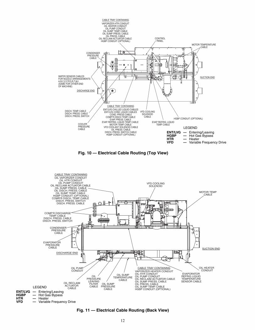
RIG MACHINE COMPONENTS — Refer to Fig. 10-26 andCarrier Certified Prints for machine component disassembly.
NOTE: Label each wire before removal when wiring must bedisconnected (see Fig. 10 and 11). Clip all wire ties necessarywhen removing pressure and temperature sensors. Disconnectall pressure transducer wires at the sensor. Temperature sensorscannot be disconnected from their cables; remove temperaturesensors from their thermowells and label as required.
HEAT EXCHANGERFRAME, PASS
ENGLISH SIRigging Weight(lb) (see Note 2)
Water Volume(gal)
Rigging Weight(kg) (see Note 2)
Water Volume(L)
FRAME 3, 1 AND 3 PASS, 150 psig (1034 kPa) N/A N/A N/A N/AFRAME 3, 2 PASS, 150 psig (1034 kPa) 365 42 166 159FRAME 4, 1 AND 3 PASS, 150 psig (1034 kPa) N/A N/A N/A N/AFRAME 4, 2 PASS, 150 psig (1034 kPa) 989 54 449 204FRAME 5, 1 AND 3 PASS, 150 psig (1034 kPa) N/A N/A N/A N/AFRAME 5, 2 PASS, 150 psig (1034 kPa) 1195 60 542 227FRAME 3, 1 AND 3 PASS, 300 psig (2068 kPa) N/A N/A N/A N/AFRAME 3, 2 PASS, 300 psig (2068 kPa) 430 42 195 159FRAME 4, 1 AND 3 PASS, 300 psig (2068 kPa) N/A N/A N/A N/AFRAME 4, 2 PASS, 300 psig (2068 kPa) 1641 47 744 178FRAME 5, 1 AND 3 PASS, 300 psig (2068 kPa) N/A N/A N/A N/AFRAME 5, 2 PASS, 300 psig (2068 kPa) 1909 50 866 189
WATERBOXDESCRIPTION
COOLER CONDENSERFrame 3 Frame 4 Frame 5 Frame 3 Frame 4 Frame 5
VictaulicNozzles Flanged Victaulic
Nozzles Flanged VictaulicNozzles Flanged Victaulic
Nozzles Flanged VictaulicNozzles Flanged Victaulic
Nozzles Flanged
NIH 1 Pass Cover, 150 psig 282 318 148 185 168 229 282 318 148 185 168 229NIH 2 Pass Cover, 150 psig 287 340 202 256 222 276 287 340 191 245 224 298NIH 3 Pass Cover, 150 psig 294 310 472 488 617 634 294 310 503 519 628 655NIH Plain End, 150 psig 243 243 138 138 154 154 225 225 138 138 154 154MWB End Cover, 150 psig* 243/315 243/315 138/314 138/314 154/390 154/390 225/234 225/234 138/314 138/314 154/390 154/390NIH 1 Pass Cover, 300 psig 411 486 633 709 764 840 411 486 633 709 764 840NIH 2 Pass Cover, 300 psig 411 518 626 733 760 867 411 578 622 729 727 878NIH 3 Pass Cover, 300 psig 433 468 660 694 795 830 433 468 655 689 785 838NIH Plain End, 300 psig 291 291 522 522 658 658 270 270 522 522 658 658MWB End Cover, 300 psig* 445/619 445/619 522/522 522/522 658/658 658/658 359/474 359/474 522/522 522/522 658/658 658/658
WATERBOXDESCRIPTION
COOLER CONDENSERFrame 3 Frame 4 Frame 5 Frame 3 Frame 4 Frame 5
VictaulicNozzles Flanged Victaulic
Nozzles Flanged VictaulicNozzles Flanged Victaulic
Nozzles Flanged VictaulicNozzles Flanged Victaulic
Nozzles Flanged
NIH 1 Pass Cover, 150 psig 128 144 67 84 76 104 128 144 67 84 76 104NIH 2 Pass Cover, 150 psig 130 154 92 116 101 125 130 154 87 111 102 135NIH 3 Pass Cover, 150 psig 133 141 214 221 280 288 133 141 228 235 285 297NIH Plain End, 150 psig 110 110 63 63 70 70 102 102 63 63 70 70MWB End Cover, 150 psig* 110/143 110/143 63/142 63/142 70/177 70/177 102/106 102/106 63/142 63/142 70/177 70/177NIH 1 Pass Cover, 300 psig 186 220 287 322 347 381 186 220 287 322 346 381NIH 2 Pass Cover, 300 psig 186 235 284 332 344 393 186 235 282 331 330 398NIH 3 Pass Cover, 300 psig 196 212 299 315 361 376 196 212 297 313 356 380NIH Plain End, 300 psig 132 132 237 237 298 298 122 122 237 237 298 298MWB End Cover, 300 psig* 202/281 202/281 237/237 237/237 298/298 298/298 163/215 163/215 237/237 237/237 298/298 298/298
NIH — Nozzle-in-HeadMWB — Marine Waterbox
IMPORTANT: Only a qualified service technicianshould perform this operation.
WARNING
Do not attempt to disconnect flanges while the machine isunder pressure. Failure to relieve pressure can result in per-sonal injury or damage to the unit.
CAUTION
Before rigging the compressor, disconnect all wires enter-ing the power panel.
12
MOTOR TEMPERATURECABLE
CONTROLPANEL
VAPORIZER HTR CONDUITOIL HEATER CONDUIT
OIL PUMP CONDUITOIL SUMP TEMP. CABLE
OIL SUMP PRESS. CABLEOIL PRESS. CABLE
OIL RECLAIM ACTUATOR CABLEHGBP CONDUIT (OPTIONAL)
CONDENSERPRESSURE
CABLE
WATER SENSOR CABLESFOR NOZZLE ARRANGEMENTSA,B,C,E,F,P,Q,R,T,&U(SAME FOR OTHER ENDOF MACHINE)
DISCH. TEMP. CABLEDISCH. PRESS. CABLEDISCH. PRESS. SWITCH
ENT/LVG CHILLED LIQUID CABLESENT/LVG COND. LIQUID CABLES
COND, PRESS CABLECOMP’R DISCH TEMP. CABLE
EVAP. PRESS. CABLEEVAP. REFRIG. LIQUID TEMP. CABLE
MOTOR TEMP. CABLEVFD COOLANT SOLENOID CABLE
OIL PRESS. CABLEDISCH. PRESS. SWITCH CABLE
HGBP CONDUIT (OPTIONAL)
VFD COOLINGSOLENOID
CABLE
EVAP REFRIG. LIQUIDTEMP. CABLE
HGBP CONDUIT (OPTIONAL)
SUCTION END
DISCHARGE END
COOLERPRESSURECABLE
CABLE TRAY CONTAINING
CABLE TRAY CONTAINING
OIL VAPORIZER CONDUITOIL HTR CONDUIT
OIL PUMP CONDUITOIL RECLAIM ACTUATOR CABLE
OIL SUMP PRESS. CABLEOIL DISCH. PRESS. CABLEOIL SUMP TEMP. CABLE
HGBP CONDUIT (OPTIONAL)COMR’R DISCH. TEMP. CABLE
DISCH. PRESS. SWITCHDISCH. PRESS. CABLE
COMP’R DISCHARGETEMP. CABLE
DISCH. PRESS. CABLEDISCH. PRESS. SWITCH
CONDENSER PRESSURE
CABLE
EVAPORATOR PRESSURE
CABLE
OIL PUMPCONDUIT
OIL RECLAIMACTUATOR
CABLE
OIL SUMPPRESSURE
CABLE
OIL SUMPTEMPERATURE
CABLE
VAPORIZER HEATER CONDUITOIL HTR CONDUITOIL PUMP CONDUITOIL RECLAIM ACTUATOR CABLEOIL SUMP PRESS. CABLEOIL PRESS. CABLEOIL SUMP TEMP. CABLEHGBP CONDUIT (OPTIONAL)
EVAPORATORREFRIG LIQUID TEMPERATURESENSOR CABLE
OIL HEATER CONDUIT
SUCTION END
DISCHARGE END
MOTOR TEMPCABLE
VFD COOLINGSOLENOID
OILPRESSURE
LEAVINGFILTERCABLE
CABLE TRAY CONTAINING
CABLE TRAY CONTAINING
Fig. 10 — Electrical Cable Routing (Top View)
Fig. 11 — Electrical Cable Routing (Back View)
LEGENDENT/LVG — Entering/LeavingHGBP — Hot Gas BypassHTR — HeaterVFD — Variable Frequency Drive
a23-1558
a23-1559 LEGENDENT/LVG — Entering/LeavingHGBP — Hot Gas BypassHTR — HeaterVFD — Variable Frequency Drive
13
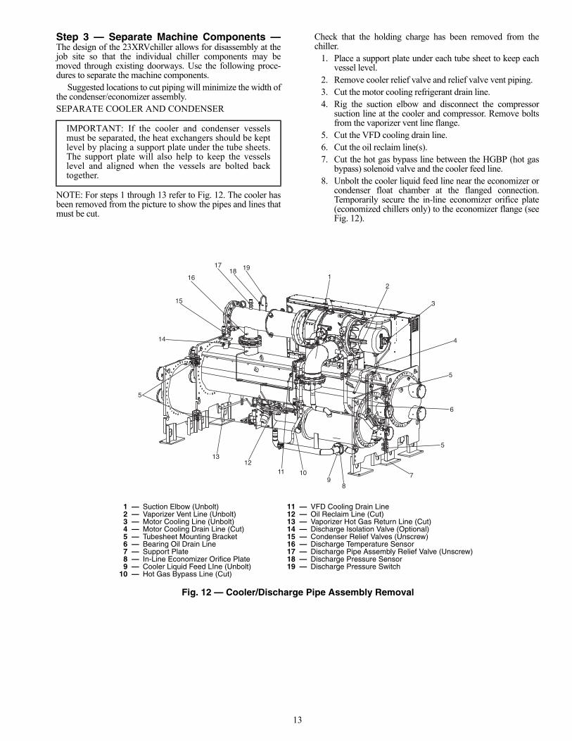
Step 3 — Separate Machine Components —The design of the 23XRVchiller allows for disassembly at thejob site so that the individual chiller components may bemoved through existing doorways. Use the following proce-dures to separate the machine components.
Suggested locations to cut piping will minimize the width ofthe condenser/economizer assembly.SEPARATE COOLER AND CONDENSER
NOTE: For steps 1 through 13 refer to Fig. 12. The cooler hasbeen removed from the picture to show the pipes and lines thatmust be cut.
Check that the holding charge has been removed from thechiller.
1. Place a support plate under each tube sheet to keep eachvessel level.
2. Remove cooler relief valve and relief valve vent piping.3. Cut the motor cooling refrigerant drain line.4. Rig the suction elbow and disconnect the compressor
suction line at the cooler and compressor. Remove boltsfrom the vaporizer vent line flange.
5. Cut the VFD cooling drain line.6. Cut the oil reclaim line(s).7. Cut the hot gas bypass line between the HGBP (hot gas
bypass) solenoid valve and the cooler feed line.8. Unbolt the cooler liquid feed line near the economizer or
condenser float chamber at the flanged connection.Temporarily secure the in-line economizer orifice plate(economized chillers only) to the economizer flange (seeFig. 12).
IMPORTANT: If the cooler and condenser vesselsmust be separated, the heat exchangers should be keptlevel by placing a support plate under the tube sheets.The support plate will also help to keep the vesselslevel and aligned when the vessels are bolted backtogether.
191817
16
15
14
5
1312
11 109
8
7
5
6
5
4
3
21
1 — Suction Elbow (Unbolt) 11 — VFD Cooling Drain Line2 — Vaporizer Vent Line (Unbolt) 12 — Oil Reclaim Line (Cut)3 — Motor Cooling Line (Unbolt) 13 — Vaporizer Hot Gas Return Line (Cut)4 — Motor Cooling Drain Line (Cut) 14 — Discharge Isolation Valve (Optional)5 — Tubesheet Mounting Bracket 15 — Condenser Relief Valves (Unscrew)6 — Bearing Oil Drain Line 16 — Discharge Temperature Sensor7 — Support Plate 17 — Discharge Pipe Assembly Relief Valve (Unscrew)8 — In-Line Economizer Orifice Plate 18 — Discharge Pressure Sensor9 — Cooler Liquid Feed LIne (Unbolt) 19 — Discharge Pressure Switch
10 — Hot Gas Bypass Line (Cut)
Fig. 12 — Cooler/Discharge Pipe Assembly Removal
a23-1560
14
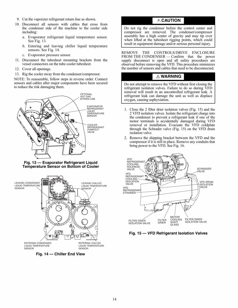
9. Cut the vaporizer refrigerant return line as shown.10. Disconnect all sensors with cables that cross from
the condenser side of the machine to the cooler sideincluding:a. Evaporator refrigerant liquid temperature sensor.
See Fig. 13.b. Entering and leaving chiller liquid temperature
sensors. See Fig. 14.c. Evaporator pressure sensor.
11. Disconnect the tubesheet mounting brackets from thevessel connectors on the tube cooler tubesheet.
12. Cover all openings.13. Rig the cooler away from the condenser/compressor.NOTE: To reassemble, follow steps in reverse order. Connectsensors and cables after major components have been securedto reduce the risk damaging them.
REMOVE THE CONTROLS/DRIVE ENCLOSUREFROM THE CONDENSER — Confirm that the powersupply disconnect is open and all safety procedures areobserved before removing the VFD. This procedure minimizesthe number of sensors and cables that need to be disconnected.
1. Close the 2 filter drier isolation valves (Fig. 15) and the2 VFD isolation valves. Isolate the refrigerant charge intothe condenser to prevent a refrigerant leak if one of themotor terminals is accidentally damaged during VFDremoval or installation. Evacuate the VFD coldplatethrough the Schrader valve (Fig. 15) on the VFD drainisolation valve.
2. Remove the shipping bracket between the VFD and thecompressor if it is still in place. Remove any conduits thatbring power to the VFD. See Fig. 16.
OPTIONALHOT GASBYPASS LINE
EVAPORATORREFRIGERANTLIQUIDTEMPERATURESENSOR
COOLERREFRIGERANTPUMPOUTVALVE
Fig. 13 — Evaporator Refrigerant Liquid Temperature Sensor on Bottom of Cooler
LEAVING CHILLEDLIQUID TEMPERATURESENSOR
ENTERING CHILLEDLIQUID TEMPERATURESENSOR
ENTERING CONDENSERLIQUID TEMPERATURESENSOR
LEAVING CONDENSERLIQUID TEMPERATURESENSOR
Fig. 14 — Chiller End View
a23-1563
a23-1635
CAUTION
Do not rig the condenser before the control center andcompressor are removed. The condenser/compressorassembly has a high center of gravity and may tip overwhen lifted at the tubesheet rigging points, which couldresult in equipment damage and/or serious personal injury.
WARNING
Do not attempt to remove the VFD without first closing therefrigerant isolation valves. Failure to do so during VFDremoval will result in an uncontrolled refrigerant leak. Arefrigerant leak can damage the unit as well as displaceoxygen, causing asphyxiation.
VFD REFRIGERANTCOOLING SOLENOIDVALVE
VFD REFRIGERANTCOOLING ISOLATIONVALVE
VFD REFRIGERANTSTRAINER
FILTER DRIERISOLATION VALVE
FILTER DRIER
MOTORCOOLINGSIGHTGLASS
FILTER DRIERISOLATION VALVE
SCHRADERVALVE
VFD DRAINISOLATIONVALVE
Fig. 15 — VFD Refrigerant Isolation Valves
a23-1564
15
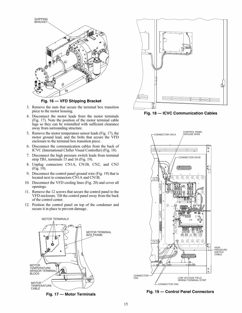
3. Remove the nuts that secure the terminal box transitionpiece to the motor housing.
4. Disconnect the motor leads from the motor terminals(Fig. 17). Note the position of the motor terminal cablelugs so they can be reinstalled with sufficient clearanceaway from surrounding structure.
5. Remove the motor temperature sensor leads (Fig. 17), themotor ground lead, and the bolts that secure the VFDenclosure to the terminal box transition piece.
6. Disconnect the communication cables from the back ofICVC (International Chiller Visual Controller) (Fig. 18).
7. Disconnect the high pressure switch leads from terminalstrip TB1, terminals 15 and 16 (Fig. 19).
8. Unplug connectors CN1A, CN1B, CN2, and CN3(Fig. 19).
9. Disconnect the control panel ground wire (Fig. 19) that islocated next to connectors CN1A and CN1B.
10. Disconnect the VFD cooling lines (Fig. 20) and cover allopenings.
11. Remove the 12 screws that secure the control panel to theVFD enclosure. Tilt the control panel away from the backof the control center.
12. Position the control panel on top of the condenser andsecure it in place to prevent damage.
SHIPPINGBRACKET
Fig. 16 — VFD Shipping Bracket
a23-1565
MOTOR TERMINALBOX FRAME
MOTOR TEMPERATURECABLE
MOTOR TEMPERATURESENSOR TERMINALBLOCK
MOTOR TERMINALS
Fig. 17 — Motor Terminals
a23-1566
Fig. 18 — ICVC Communication Cables
a23-1567
CONNECTOR CN1A
CONNECTOR CN1B
CONTROL PANELGROUND WIRE
CONNECTOR CN2
CONNECTOR CN3
LOW VOLTAGE FIELDWIRING TERMINAL STRIP
HIGH PRESSURESWITCH CABLE
Fig. 19 — Control Panel Connectors
a23-1570
16
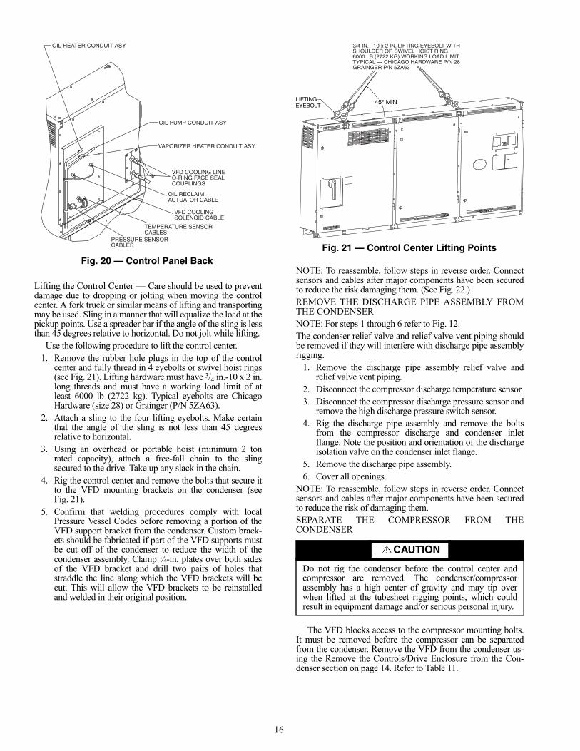
Lifting the Control Center — Care should be used to preventdamage due to dropping or jolting when moving the controlcenter. A fork truck or similar means of lifting and transportingmay be used. Sling in a manner that will equalize the load at thepickup points. Use a spreader bar if the angle of the sling is lessthan 45 degrees relative to horizontal. Do not jolt while lifting.
Use the following procedure to lift the control center.1. Remove the rubber hole plugs in the top of the control
center and fully thread in 4 eyebolts or swivel hoist rings(see Fig. 21). Lifting hardware must have 3/4 in.-10 x 2 in.long threads and must have a working load limit of atleast 6000 lb (2722 kg). Typical eyebolts are ChicagoHardware (size 28) or Grainger (P/N 5ZA63).
2. Attach a sling to the four lifting eyebolts. Make certainthat the angle of the sling is not less than 45 degreesrelative to horizontal.
3. Using an overhead or portable hoist (minimum 2 tonrated capacity), attach a free-fall chain to the slingsecured to the drive. Take up any slack in the chain.
4. Rig the control center and remove the bolts that secure itto the VFD mounting brackets on the condenser (seeFig. 21).
5. Confirm that welding procedures comply with localPressure Vessel Codes before removing a portion of theVFD support bracket from the condenser. Custom brack-ets should be fabricated if part of the VFD supports mustbe cut off of the condenser to reduce the width of thecondenser assembly. Clamp ¼-in. plates over both sidesof the VFD bracket and drill two pairs of holes thatstraddle the line along which the VFD brackets will becut. This will allow the VFD brackets to be reinstalledand welded in their original position.
NOTE: To reassemble, follow steps in reverse order. Connectsensors and cables after major components have been securedto reduce the risk damaging them. (See Fig. 22.)REMOVE THE DISCHARGE PIPE ASSEMBLY FROMTHE CONDENSERNOTE: For steps 1 through 6 refer to Fig. 12. The condenser relief valve and relief valve vent piping shouldbe removed if they will interfere with discharge pipe assemblyrigging.
1. Remove the discharge pipe assembly relief valve andrelief valve vent piping.
2. Disconnect the compressor discharge temperature sensor.3. Disconnect the compressor discharge pressure sensor and
remove the high discharge pressure switch sensor.4. Rig the discharge pipe assembly and remove the bolts
from the compressor discharge and condenser inletflange. Note the position and orientation of the dischargeisolation valve on the condenser inlet flange.
5. Remove the discharge pipe assembly.6. Cover all openings.
NOTE: To reassemble, follow steps in reverse order. Connectsensors and cables after major components have been securedto reduce the risk of damaging them.SEPARATE THE COMPRESSOR FROM THECONDENSER
The VFD blocks access to the compressor mounting bolts.It must be removed before the compressor can be separatedfrom the condenser. Remove the VFD from the condenser us-ing the Remove the Controls/Drive Enclosure from the Con-denser section on page 14. Refer to Table 11.
OIL HEATER CONDUIT ASY
OIL PUMP CONDUIT ASY
VAPORIZER HEATER CONDUIT ASY
OIL RECLAIMACTUATOR CABLE
VFD COOLING LINEO-RING FACE SEALCOUPLINGS
VFD COOLING SOLENOID CABLE
TEMPERATURE SENSORCABLES
PRESSURE SENSORCABLES
Fig. 20 — Control Panel Backa23-1571
CAUTION
Do not rig the condenser before the control center andcompressor are removed. The condenser/compressorassembly has a high center of gravity and may tip overwhen lifted at the tubesheet rigging points, which couldresult in equipment damage and/or serious personal injury.
45° MINLIFTING EYEBOLT
3/4 IN. - 10 x 2 IN. LIFTING EYEBOLT WITHSHOULDER OR SWIVEL HOIST RING6000 LB (2722 KG) WORKING LOAD LIMITTYPICAL — CHICAGO HARDWARE P/N 28GRAINGER P/N 5ZA63
Fig. 21 — Control Center Lifting Points
a23-1561
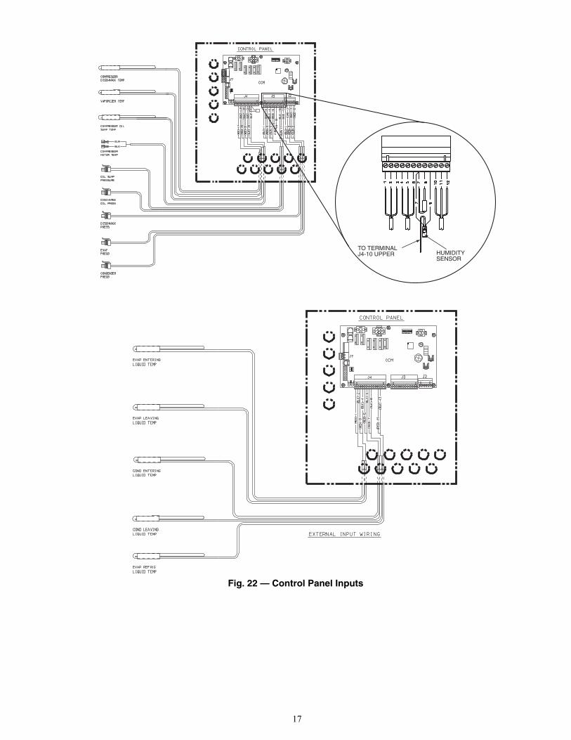
17
TO TERMINALJ4-10 UPPER HUMIDITY
SENSOR
Fig. 22 — Control Panel Inputs
a23-1568
a23-1569
18
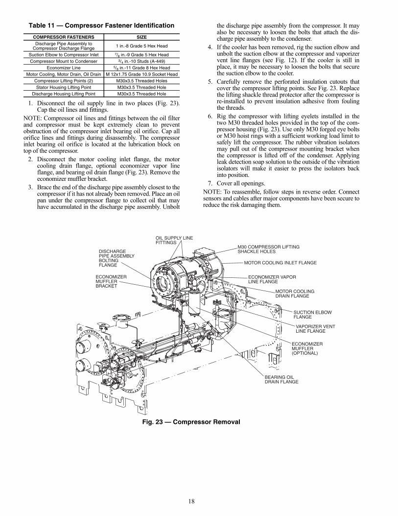
Table 11 — Compressor Fastener Identification
1. Disconnect the oil supply line in two places (Fig. 23).Cap the oil lines and fittings.
NOTE: Compressor oil lines and fittings between the oil filterand compressor must be kept extremely clean to preventobstruction of the compressor inlet bearing oil orifice. Cap allorifice lines and fittings during disassembly. The compressorinlet bearing oil orifice is located at the lubrication block ontop of the compressor.
2. Disconnect the motor cooling inlet flange, the motorcooling drain flange, optional economizer vapor lineflange, and bearing oil drain flange (Fig. 23). Remove theeconomizer muffler bracket.
3. Brace the end of the discharge pipe assembly closest to thecompressor if it has not already been removed. Place an oilpan under the compressor flange to collect oil that mayhave accumulated in the discharge pipe assembly. Unbolt
the discharge pipe assembly from the compressor. It mayalso be necessary to loosen the bolts that attach the dis-charge pipe assembly to the condenser.
4. If the cooler has been removed, rig the suction elbow andunbolt the suction elbow at the compressor and vaporizervent line flanges (see Fig. 12). If the cooler is still inplace, it may be necessary to loosen the bolts that securethe suction elbow to the cooler.
5. Carefully remove the perforated insulation cutouts thatcover the compressor lifting points. See Fig. 23. Replacethe lifting shackle thread protector after the compressor isre-installed to prevent insulation adhesive from foulingthe threads.
6. Rig the compressor with lifting eyelets installed in thetwo M30 threaded holes provided in the top of the com-pressor housing (Fig. 23). Use only M30 forged eye boltsor M30 hoist rings with a sufficient working load limit tosafely lift the compressor. The rubber vibration isolatorsmay pull out of the compressor mounting bracket whenthe compressor is lifted off of the condenser. Applyingleak detection soap solution to the outside of the vibrationisolators will make it easier to press the isolators backinto position.
7. Cover all openings.NOTE: To reassemble, follow steps in reverse order. Connectsensors and cables after major components have been secure toreduce the risk damaging them.
COMPRESSOR FASTENERS SIZEDischarge Pipe Assembly to
Compressor Discharge Flange 1 in.-8 Grade 5 Hex Head
Suction Elbow to Compressor Inlet 7/8 in.-9 Grade 5 Hex HeadCompressor Mount to Condenser 3/4 in.-10 Studs (A-449)
Economizer Line 5/8 in.-11 Grade 8 Hex HeadMotor Cooling, Motor Drain, Oil Drain M 12x1.75 Grade 10.9 Socket Head
Compressor Lifting Points (2) M30x3.5 Threaded HolesStator Housing Lifting Point M30x3.5 Threaded Hole
Discharge Housing Lifting Point M30x3.5 Threaded Hole
ECONOMIZERMUFFLERBRACKET
DISCHARGEPIPE ASSEMBLYBOLTINGFLANGE
OIL SUPPLY LINEFITTINGS
M30 COMPRESSOR LIFTINGSHACKLE HOLES
MOTOR COOLING INLET FLANGE
ECONOMIZER VAPORLINE FLANGE
MOTOR COOLING DRAIN FLANGE
SUCTION ELBOWFLANGE
VAPORIZER VENTLINE FLANGE
ECONOMIZERMUFFLER(OPTIONAL)
BEARING OILDRAIN FLANGE
Fig. 23 — Compressor Removal
a23-1572
19
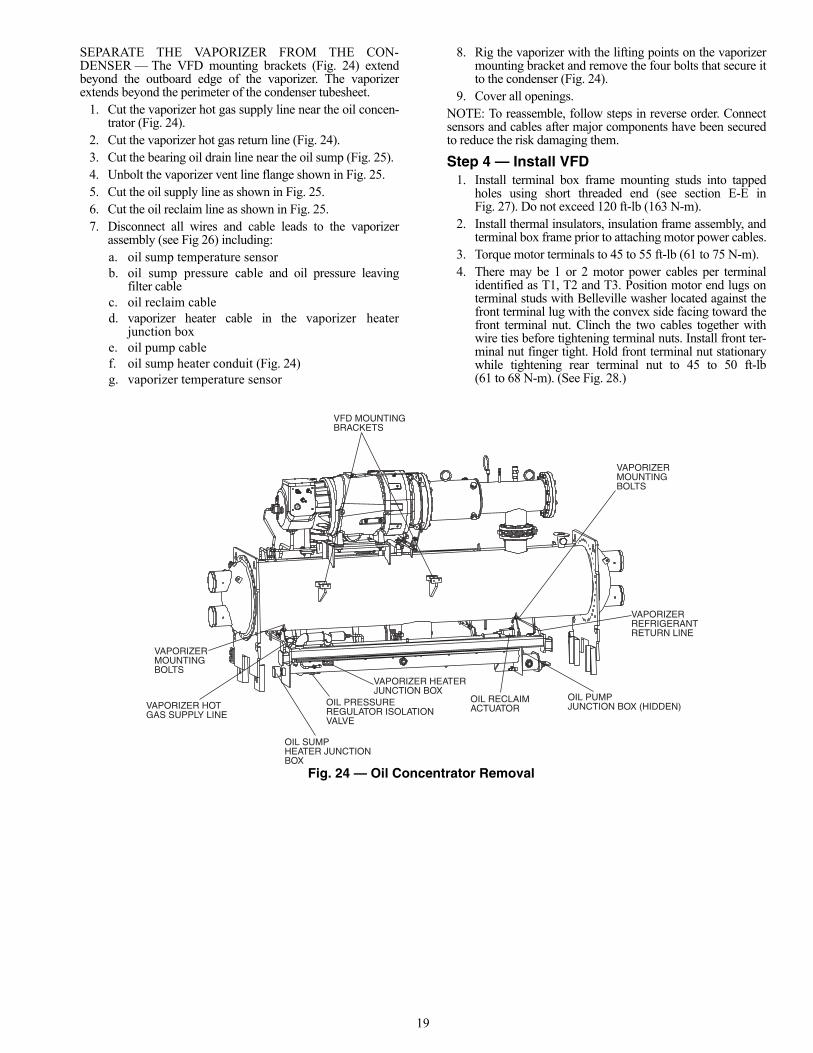
SEPARATE THE VAPORIZER FROM THE CON-DENSER — The VFD mounting brackets (Fig. 24) extendbeyond the outboard edge of the vaporizer. The vaporizerextends beyond the perimeter of the condenser tubesheet.
1. Cut the vaporizer hot gas supply line near the oil concen-trator (Fig. 24).
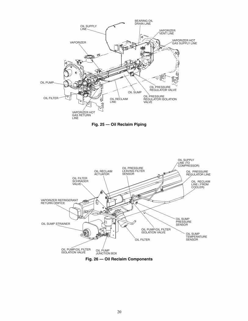
2. Cut the vaporizer hot gas return line (Fig. 24). 3. Cut the bearing oil drain line near the oil sump (Fig. 25).4. Unbolt the vaporizer vent line flange shown in Fig. 25.5. Cut the oil supply line as shown in Fig. 25.6. Cut the oil reclaim line as shown in Fig. 25.7. Disconnect all wires and cable leads to the vaporizer
assembly (see Fig 26) including:a. oil sump temperature sensorb. oil sump pressure cable and oil pressure leaving
filter cablec. oil reclaim cabled. vaporizer heater cable in the vaporizer heater
junction boxe. oil pump cablef. oil sump heater conduit (Fig. 24)g. vaporizer temperature sensor
8. Rig the vaporizer with the lifting points on the vaporizermounting bracket and remove the four bolts that secure itto the condenser (Fig. 24).
9. Cover all openings.NOTE: To reassemble, follow steps in reverse order. Connectsensors and cables after major components have been securedto reduce the risk damaging them.
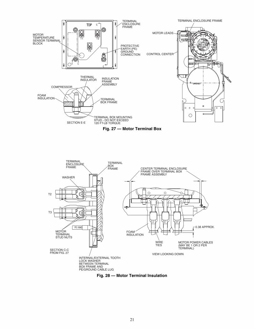
Step 4 — Install VFD1. Install terminal box frame mounting studs into tapped
holes using short threaded end (see section E-E inFig. 27). Do not exceed 120 ft-lb (163 N-m).
2. Install thermal insulators, insulation frame assembly, andterminal box frame prior to attaching motor power cables.
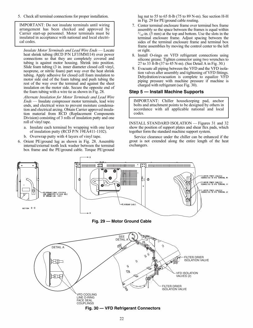
3. Torque motor terminals to 45 to 55 ft-lb (61 to 75 N-m).4. There may be 1 or 2 motor power cables per terminal
identified as T1, T2 and T3. Position motor end lugs onterminal studs with Belleville washer located against thefront terminal lug with the convex side facing toward thefront terminal nut. Clinch the two cables together withwire ties before tightening terminal nuts. Install front ter-minal nut finger tight. Hold front terminal nut stationarywhile tightening rear terminal nut to 45 to 50 ft-lb(61 to 68 N-m). (See Fig. 28.)
VFD MOUNTINGBRACKETS
VAPORIZERMOUNTINGBOLTS
VAPORIZER HOTGAS SUPPLY LINE
OIL SUMPHEATER JUNCTIONBOX
OIL PRESSUREREGULATOR ISOLATIONVALVE
VAPORIZER HEATERJUNCTION BOX
OIL RECLAIMACTUATOR
OIL PUMPJUNCTION BOX (HIDDEN)
VAPORIZERREFRIGERANTRETURN LINE
VAPORIZERMOUNTINGBOLTS
Fig. 24 — Oil Concentrator Removala23-1573
20
OIL SUPPLYLINE
VAPORIZER
OIL PUMP
OIL FILTER
VAPORIZER HOTGAS RETURNLINE
OIL RECLAIMLINE
OIL SUMPOIL PRESSUREREGULATOR ISOLATIONVALVE
OIL PRESSUREREGULATOR VALVE
VAPORIZER HOTGAS SUPPLY LINE
VAPORIZER VENT LINE
BEARING OILDRAIN LINE
Fig. 25 — Oil Reclaim Piping
a23-1574
OIL SUMPPRESSURESENSOR
OIL PUMP/OIL FILTERISOLATION VALVE
OIL FILTER
OIL PUMPJUNCTION BOX
OIL PUMP/OIL FILTERISOLATION VALVE
OIL SUMP STRAINER
VAPORIZER REFRIGERANTRETURN ORIFICE
OIL FILTERSCHRADERVALVE
OIL RECLAIMACTUATOR
OIL PRESSURELEAVING FILTER SENSOR
OIL SUPPLYLINE (TO COMPRESSOR)
OIL PRESSUREREGULATOR LINE
OIL RECLAIMLINE ( FROMCOOLER)
OIL SUMPTEMPERATURESENSOR
Fig. 26 — Oil Reclaim Components
a23-1575
21
MOTOR LEADS
CONTROL CENTER
TERMINAL ENCLOSURE FRAME
THERMAL INSULATOR INSULATION
FRAMEASSEMBLY
TERMINALBOX FRAME
COMPRESSOR
FOAM INSULATION
TERMINAL BOX MOUNTINGSTUD - DO NOT EXCEED120 FT-LB TORQUE
T1 T2
T3
TERMINALENCLOSUREFRAME
MOTORTEMPERATURESENSOR TERMINALBLOCK
PROTECTIVEEARTH (PE)GROUNDCONNECTION
SECTION E-E
Fig. 27 — Motor Terminal Box
a23-1576
CENTER TERMINAL ENCLOSUREFRAME OVER TERMINAL BOXFRAME ASSEMBLY
MOTOR POWER CABLES(MAY BE 1 OR 2 PERTERMINAL)
0.38 APPROX.
FOAMINSULATION
WIRETIES
VIEW LOOKING DOWNINTERNAL/EXTERNAL TOOTHLOCK WASHERBETWEEN TERMINALBOX FRAME ANDPE/GROUND CABLE LUG
MOTORTERMINALSTUD NUTS
WASHER
TERMINALENCLOSUREFRAME
TERMINALBOXFRAME
T2
T3
SECTION C-CFROM FIG. 27
Fig. 28 — Motor Terminal Insulation
a23-1577
22
5. Check all terminal connections for proper installation.
Insulate Motor Terminals and Lead Wire Ends — Locateheat shrink tubing (RCD P/N LF33MM114) over powerconnections so that they are completely covered andtubing is against motor housing. Shrink into position.Slide foam tubing (3 in. inner diameter closed cell vinyl,neoprene, or nitrile foam) part way over the heat shrinktubing. Apply adhesive for closed cell foam insulation tomotor side end of the foam tubing and push tubing therest of the way over the terminal and against the sheetinsulation on the motor side. Secure the opposite end ofthe foam tubing with a wire tie as shown in Fig. 28.Alternate Insulation for Motor Terminals and Lead WireEnds — Insulate compressor motor terminals, lead wireends, and electrical wires to prevent moisture condensa-tion and electrical arcing. Obtain Carrier approved insula-tion material from RCD (Replacement ComponentsDivision) consisting of 3 rolls of insulation putty and oneroll of vinyl tape.a. Insulate each terminal by wrapping with one layer
of insulation putty (RCD P/N 19EA411-1102).b. Overwrap putty with 4 layers of vinyl tape.
6. Orient PE/ground lug as shown in Fig. 28. Assembleinternal/external tooth lock washer between the terminalbox frame and the PE/ground cable. Torque PE/ground
lug nut to 55 to 65 ft-lb (75 to 89 N-m). See section H-Hin Fig. 29 for PE/ground cable routing.
7. Center terminal enclosure frame over terminal box frameassembly so the space between the frames is equal within3/16-in. (5 mm) at the top and bottom. Use the slots in theterminal enclosure frame. Adjust spacing between thesides of the terminal enclosure frame and terminal boxframe assemblies by moving the control center to the leftor right.
8. Install O-rings on VFD refrigerant connections usingsilicone grease. Tighten connector using two wrenches to27 to 33 ft-lb (37 to 45 N-m). (See Detail A in Fig. 30.)
9. Evacuate all piping between the VFD and the VFD isola-tion valves after assembly and tightening of VFD fittings.Dehydration/evacuation is complete to equalize VFDpiping pressure with machine pressure if machine ischarged with refrigerant (see Fig. 30).
Step 5 — Install Machine Supports
INSTALL STANDARD ISOLATION — Figures 31 and 32show the position of support plates and shear flex pads, whichtogether form the standard machine support system.
Service clearance under the chiller can be enhanced if thegrout is not extended along the entire length of the heatexchangers.
IMPORTANT: Do not insulate terminals until wiringarrangement has been checked and approved byCarrier start-up personnel. Motor terminals must beinsulated in acceptance with national and local electri-cal codes.
IMPORTANT: Chiller housekeeping pad, anchorbolts and attachment points to be designed by others inaccordance with all applicable national and localcodes.
VFD COOLINGLINE O-RINGFACE SEALCOUPLINGS
DETAIL A
SEE DETAIL A
FILTER DRIERISOLATION VALVE
VFD ISOLATIONVALVES (2)
FILTER DRIERISOLATION VALVE
Fig. 29 — Motor Ground Cable
Fig. 30 — VFD Refrigerant Connectors
a23-1578
a23-1579

23
INSTALL ACCESSORY ISOLATION (if required) — Un-even floors or other considerations may dictate the use ofaccessory soleplates (supplied by Carrier for field installation)and leveling pads. Refer to Fig. 33.
Level machine by using jacking screws in isolation sole-plates. Use a level at least 24-in. (610 mm) long.
For adequate and long lasting machine support, propergrout selection and placement is essential. Carrier recommendsthat only pre-mixed, epoxy type, non-shrinking grout be usedfor machine installation. Follow manufacturer’s instructions inapplying grout.
1. Check machine location prints for required groutthickness.
2. Carefully wax jacking screws for easy removal fromgrout.
3. Grout must extend above the base of the soleplate andthere must be no voids in grout beneath the plates.
4. Allow grout to set and harden, per manufacturer’sinstructions, before starting machine.
5. Remove jacking screws from leveling pads after grouthas hardened.
.
23XRVHEAT EXCHANGER
SIZE
DIMENSIONS (ft-in.)
A B C D E F G
30-32 12-103/4 5-51/4 0 0-35/8 1-31/4 0-9 0-1/235-37 14- 71/4 5-51/4 0 0-35/8 1-31/4 0-9 0-1/240-42 12-103/4 6-0 0-11/2 0-35/8 1-31/4 0-9 0-1/245-47 14- 71/4 6-0 0-11/2 0-35/8 1-31/4 0-9 0-1/250-52 12-103/4 6-51/2 0-1/2 0-35/8 1-31/4 0-9 0-1/255-57 14- 71/4 6-51/2 0-1/2 0-35/8 1-31/4 0-9 0-1/2
Fig. 31 — 23XRV Machine Footprint
a23-1534
IMPORTANT: Chiller support plates must be levelwithin 1/2 in. from one end to the other end of the heatexchangers for effective oil reclaim system operation.
VIEW Y-Y
a23-46
NOTES:1. Dimensions in ( ) are in millimeters.2. Isolation package includes 4 shear flex pads.
Fig. 32 — Standard Isolation
LEGEND
NOTES:1. Dimensions in ( ) are in millimeters.2. Accessory (Carrier supplied, field installed) soleplate package
includes 4 soleplates, 16 jacking screws and leveling pads.3. Jacking screws to be removed after grout has set.4. Thickness of grout will vary, depending on the amount neces-
sary to level chiller. Use only pre-mixed non-shrinking grout,Ceilcote 748 OR Chemrex Embeco 636 Plus Grout 0-1½(38.1) to 0-2¼ (57) thick.
Fig. 33 — Accessory Isolation
HRS — Hot Rolled Steel
VIEW X-X
ACCESSORY SOLEPLATE DETAIL
a19-1109
a19-1110

24
INSTALL SPRING ISOLATION
Spring isolation may be purchased as an accessory fromCarrier for field installation. It may also be field supplied andinstalled. Spring isolators may be placed directly undermachine support plates or located under machine soleplates.See Fig. 34. Consult job data for specific arrangement. Lowprofile spring isolation assemblies can be field supplied to keepthe machine at a convenient working height.
Obtain specific details on spring mounting and machineweight distribution from job data. Also, check job data formethods to support and isolate pipes that are attached to springisolated machines.
Step 6 — Connect Piping
INSTALL WATER PIPING TO HEAT EXCHANGERS —Refer to Table 4 for nozzle sizes. Install piping using job data,piping drawings, and procedures outlined below. A typicalpiping installation is shown in Fig. 35.
1. Offset pipe flanges to permit removal of waterbox coverfor maintenance and to provide clearance for pipe clean-ing. No flanges are necessary with marine waterboxoption; however, water piping should not cross in front ofthe waterbox cover or access will be blocked.
2. Provide openings in water piping for required pressuregages and thermometers. For thorough mixing andtemperature stabilization, wells in the leaving water pipeshould extend inside pipe at least 2 in. (51 mm).
3. Install air vents at all high points in piping to remove airand prevent water hammer.
4. Install pipe hangers where needed. Make sure no weightor stress is placed on waterbox nozzles or flanges.
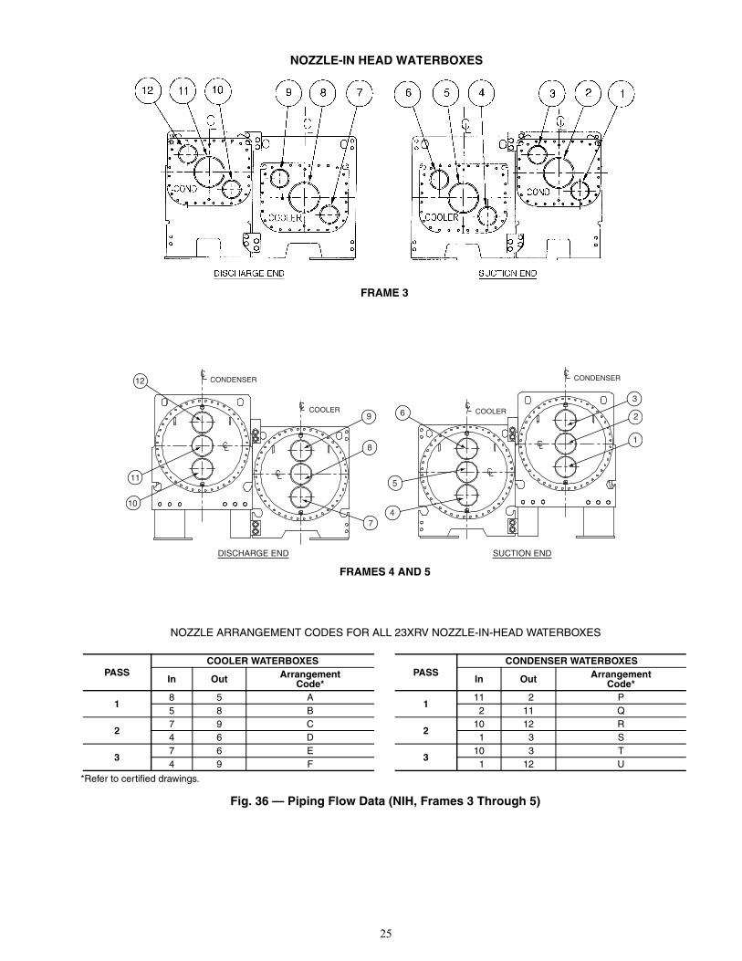
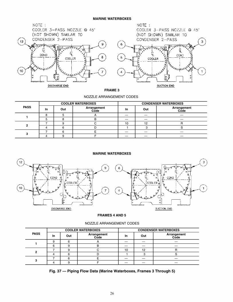
5. Water flow direction must be as specified in Fig. 36and 37.NOTE: Entering water is always the lower of the 2 noz-zles. Leaving water is always the upper nozzle for cooleror condenser.
6. Install waterbox vent and drain piping in accordance withindividual job data. All connections are 3/4-in. FPT.
7. Install waterbox drain plugs in the unused waterboxdrains and vent openings.
8. Install optional pumpout system or pumpout system andstorage tank as shown in Fig. 38-42.
IMPORTANT: Accessory spring isolation packagesare intended solely for non-seismic applications. Seis-mic applications must be designed by a registeredprofessional in accordance with all applicable nationaland local codes.
IMPORTANT: Chiller water nozzle connections to bedesigned by others in accordance with all applicablenational and local codes.
CAUTION
Remove cooler and condenser liquid temperature andoptional pressure sensors before welding connecting pipingto water nozzles. Refer to Fig. 14. Replace sensors afterwelding is complete.
Fig. 34 — 23XRV Accessory Spring Isolation (Shown with Accessory Soleplates)
NOTE: The accessory spring isolators are supplied by Carrier forinstallation in the field.
a23-1537
CAUTION
Factory-supplied insulation is not flammable but can bedamaged by welding sparks and open flame. Protect insu-lation with a wet canvas cover.
CAUTION
Never charge liquid R-134a refrigerant into the chiller ifthe pressure is less than 35 psig (241 kPa). Charge as a gasonly, with the cooler and condenser pumps running, until35 psig (241 kPa) is reached using a pumpdown. Terminatethe pumpdown mode using the ICVC. Flashing of liquidrefrigerant at low pressures can cause tube freeze-up andconsiderable damage.
PRESSUREGAGES
PIPEFLANGES
ENTERINGCONDENSERWATER
LEAVINGCONDENSERWATER
AIR VENT
PIPE HANGERS ENTERING CHILLEDWATERLEAVING CHILLED
WATER
THERMOMETEROPENING(OPTIONAL)
Fig. 35 — Typical Nozzle Pipinga23-1580
25
12
11
10
9
8
7
DISCHARGE END SUCTION END
6
5
4
3
2
1
CONDENSER CONDENSER
COOLER COOLER
NOZZLE-IN HEAD WATERBOXES
FRAME 3
FRAMES 4 AND 5
NOZZLE ARRANGEMENT CODES FOR ALL 23XRV NOZZLE-IN-HEAD WATERBOXES
Fig. 36 — Piping Flow Data (NIH, Frames 3 Through 5)
*Refer to certified drawings.
PASSCOOLER WATERBOXES
In Out ArrangementCode*
18 5 A5 8 B
27 9 C4 6 D
37 6 E4 9 F
PASSCONDENSER WATERBOXES
In Out ArrangementCode*
111 2 P
2 11 Q
210 12 R
1 3 S
310 3 T
1 12 U
a23-1538
a23-1581
26
NOZZLE ARRANGEMENT CODES
PASSCOOLER WATERBOXES CONDENSER WATERBOXES
In Out ArrangementCode In Out Arrangement
Code
18 5 A — — —5 8 B — — —
27 9 C 10 12 R4 6 D 1 3 S
37 6 E — — —4 9 F — — —
MARINE WATERBOXES
FRAME 3a23-1539
MARINE WATERBOXES
FRAMES 4 AND 5
NOZZLE ARRANGEMENT CODES
PASSCOOLER WATERBOXES CONDENSER WATERBOXES
In Out ArrangementCode In Out Arrangement
Code
19 6 A — — —6 9 B — — —
27 9 C 10 12 R4 6 D 1 3 S
37 6 E — — —4 9 F — — —
Fig. 37 — Piping Flow Data (Marine Waterboxes, Frames 3 Through 5)
a23-1540

27
LEVEL GAGE
0' - 5 1/2"[140mm]
PRESSURE GAGE
3/8" MALE FLARERELIEF VALVE CONN.
1/2" DIA. K.O.ELECTRICAL CONN.(PUMPOUT POWER)
1' - 7 "[483mm]
0' - 5 7/8 "[149mm]
(2) 1" NPT RELIEFVALVE OUTLET (SEE FIELDINSTALLATION NOTES)
0' - 9 "[229mm]TYPICAL
B
T
R
E
D
W
0'- 9 7/8" [249mm]
1" NPTLIQUID CONN. 0'- 9"
[229mm]TYPICAL
VAPOR
3/4" NPTPUMPOUT CONDENSERWATER INLET CONN.
1/2" MALE FLAREVAPOR CONN. 3/4" NPT
PUMPOUT CONDENSERWATER OUTLET CONN.
ELECTRICAL SERVICEACCESS SPACE20 3/4" X 8 3/4" X 4 1/2"(BOTH SIDES)
V
U
N
A
GM
J
K
L
F
1'-0 3/4" [324mm]
3/8" MALE FLARERELIEF VALVE CONN.
1/2" DIA. K.O.ELECTRICAL CONN.(PUMPOUT POWER)(FAR SIDE)
0'- 3 1/4" [83mm]0'- 10"
[254mm]
0'- 2 3/4" [70mm]
0'- 7 15/16" [202mm]
(FARSIDE)
C
P
S
H
DIMENSIONSENGLISH (ft-in.)
SI (mm)
TANKSIZE A B C D E F G H J K
0428 10- 5 9-10 4-41/4 2-43/4 1-23/8 3-11/4 6-43/16 3-113/8 3-47/8 2-99/16
0452 14-111/4 14- 41/2 4-81/4 2-81/2 1-41/4 3-41/2 7-21/4 4- 31/4 3-83/4 3-17/16
TANKSIZE L M N P R S T U V W
0428 3-45/8 0-31/2 4- 91/2 1-77/8 2-03/8 3-9 5-01/4 2-5 2-97/8 2-53/40452 3-81/2 0-33/8 6-115/8 1-83/4 2-05/8 4-1 5-01/2 2-51/4 2-101/8 2-6
TANKSIZE A B C D E F G H J K
0428 3175 2997 1327 730 365 946 1935 1203 1038 8520452 4553 4381 1429 826 413 1029 2191 1302 1137 951
TANKSIZE L M N P R S T U V W
0428 1032 89 1451 505 619 1143 1530 737 860 7560452 1130 86 2124 527 625 1225 1537 742 867 762
NOTES:
1. Denotes center of gravity.
2. Dimensions in [ ] are inmillimeters.
3. The weights and center ofgravity values given are for anempty storage tank.
4. For additional information onthe pumpout unit, see certifieddrawings.
5. Conduit knockout is locatedon the side of the control box.
6. 28 cubic ft storage tankweight: 2334 lb (1059 kg).
7. 52 cu ft storage tank weight:3414 lb (1549 kg).
Fig. 38 — Optional Pumpout Unit and Storage Tank
TOP VIEW
LEFT SIDE VIEW
FRONT VIEW
a23-1541
a23-1542
a23-1543

28
RATED DRY WEIGHT AND REFRIGERANT CAPACITY
ENGLISH (lb)
SI (kg)
TANKSIZE
TANK OD(in.)
DRYWEIGHT*
(lb)
R-134a MAXIMUM REFRIGERANT CAPACITY (lb)
ANSI/ASHRAE 15 UL 1963
0428 24.00 2334 1860 17160452 27.25 3414 3563 3286
TANKSIZE
TANK OD(mm)
DRYWEIGHT*
(kg)
R-134a MAXIMUM REFRIGERANT CAPACITY (kg)
ANSI/ASHRAE 15 UL 1963
0428 610 1059 844 7780452 692 1549 1616 1491
LEGEND
*The above dry weight includes the pumpout condensing unit weight of 164 lb (75 kg).
ANSI — American National Standard InstituteASHRAE — American Society of Heating, Refrigerating,
and Air Conditioning EngineersOD — Outside DiameterUL — Underwriters Laboratories
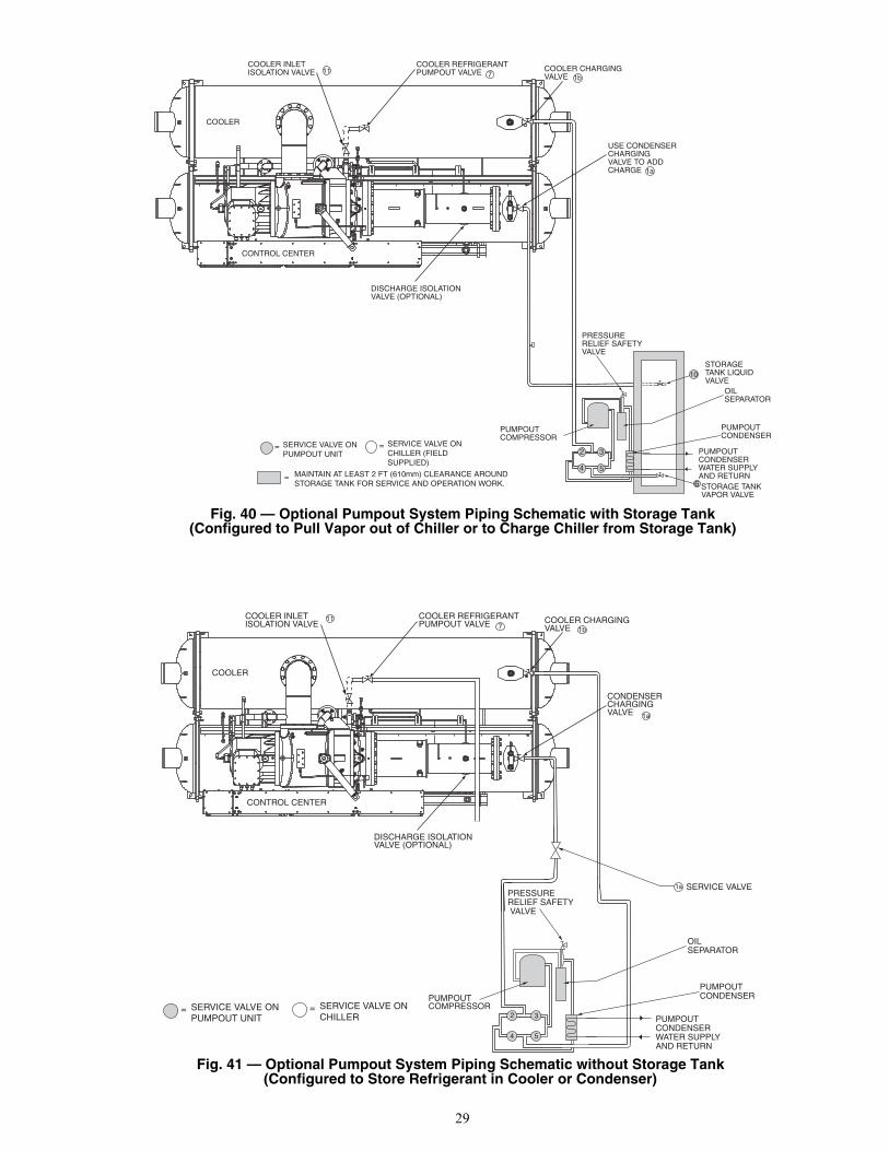
Fig. 39 — Optional Pumpout System Piping Schematic with Storage Tank(Configured to Push Liquid into Storage Tank)
COOLER
CONTROL CENTER
COOLER REFRIGERANTPUMPOUT VALVE
COOLER INLETISOLATION VALVE COOLER CHARGING
VALVE
CONDENSERCHARGINGVALVE
DISCHARGE ISOLATIONVALVE (OPTIONAL)
STORAGETANK LIQUIDVALVE
OILSEPARATOR
PUMPOUTCONDENSERWATER SUPPLYAND RETURN
PUMPOUTCONDENSER
STORAGE TANKVAPOR VALVE
2 3
4 5
PRESSURERELIEF SAFETYVALVE
PUMPOUTCOMPRESSOR
6
SERVICE VALVE ONPUMPOUT UNIT
= SERVICE VALVE ONCHILLER (FIELDSUPPLIED)
=
= MAINTAIN AT LEAST 2 FT (610mm) CLEARANCE AROUNDSTORAGE TANK FOR SERVICE AND OPERATION WORK.
10
1a
71b
11
a23-1634
29
COOLER
CONTROL CENTER
COOLER REFRIGERANTPUMPOUT VALVE COOLER CHARGING
VALVE
USE CONDENSERCHARGINGVALVE TO ADDCHARGE
DISCHARGE ISOLATIONVALVE (OPTIONAL)
STORAGETANK LIQUIDVALVE
OILSEPARATOR
PUMPOUTCONDENSERWATER SUPPLYAND RETURN
PUMPOUTCONDENSER
STORAGE TANKVAPOR VALVE
2 3
4 5
PRESSURERELIEF SAFETYVALVE
PUMPOUTCOMPRESSOR
6
SERVICE VALVE ONPUMPOUT UNIT
= SERVICE VALVE ONCHILLER (FIELDSUPPLIED)
=
= MAINTAIN AT LEAST 2 FT (610mm) CLEARANCE AROUNDSTORAGE TANK FOR SERVICE AND OPERATION WORK.
10
7COOLER INLETISOLATION VALVE
1a
1b11
COOLER
CONTROL CENTER
COOLER REFRIGERANTPUMPOUT VALVE
COOLER INLETISOLATION VALVE COOLER CHARGING
VALVE
CONDENSERCHARGINGVALVE
DISCHARGE ISOLATIONVALVE (OPTIONAL)
OILSEPARATOR
PUMPOUTCONDENSERWATER SUPPLYAND RETURN
PUMPOUTCONDENSER
2 3
4 5
PRESSURERELIEF SAFETY VALVE
PUMPOUTCOMPRESSOR
SERVICE VALVE1a
SERVICE VALVE ONPUMPOUT UNIT
= SERVICE VALVE ONCHILLER
=
7
1a
1b
11
Fig. 40 — Optional Pumpout System Piping Schematic with Storage Tank(Configured to Pull Vapor out of Chiller or to Charge Chiller from Storage Tank)
Fig. 41 — Optional Pumpout System Piping Schematic without Storage Tank(Configured to Store Refrigerant in Cooler or Condenser)
a23-1544
a23-1545

30
INSTALL VENT PIPING TO RELIEF VALVES — The23XRV chiller is factory equipped with relief valves on thecooler and condenser shells. Refer to Fig. 43 and Table 12 forsize and location of relief devices. Vent relief devices to theoutdoors in accordance with ANSI/ASHRAE 15 (latestedition) Safety Code for Mechanical Refrigeration and allother applicable codes.
1. Dual pressure relief valves are mounted on the three-wayvalves in some locations to allow testing and repair with-out transferring the refrigerant charge. Three-way valveshafts should be turned either fully clockwise or fullycounterclockwise so only one relief valve is exposed torefrigerant pressure at a time.The flow area of discharge piping routed from more thanone relief valve, or more than one heat exchanger, mustbe greater than the sum of the outlet areas of all reliefvalves that are expected to discharge simultaneously. Allrelief valves within a machinery room that are exposed torefrigerant may discharge simultaneously in the event of afire. Discharge piping should lead to the point of finalrelease as directly as possible with consideration of pres-sure drop in all sections downstream of the relief valves.
2. Provide a pipe plug near outlet side of each relief devicefor leak testing. Provide pipe fittings that allow ventpiping to be disconnected periodically for inspection ofvalve mechanism.
3. Piping to relief devices must not apply stress to thedevice. Adequately support piping. A length of flexibletubing or piping near the relief device is essential onspring-isolated machines.
4. Cover the outdoor vent with a rain cap and place acondensation drain at the low point in the vent piping toprevent water build-up on the atmospheric side of therelief device.
Step 7 — Make Electrical Connections — Fieldwiring must be installed in accordance with job wiring dia-grams and all applicable electrical codes. Refer to Fig. 44 and45 for typical wiring and component layout.
DANGER
Refrigerant discharged into confined spaces can displaceoxygen and cause asphyxiation.
COMPRESSOR
OILSEPARATOR
CONDENSER LEAVINGWATER
ENTERINGWATER
VALVE5
VALVE4
VALVE2
CONTROLPANEL
FRAMEASSEMBLY
OILHEATER
VALVE3
OIL FILLFITTING
Fig. 42 — Pumpout Unit
a23-1546
DANGER
Only qualified electrical personnel familiar with the con-struction and operation of this equipment and the hazardsinvolved should install, adjust, operate, or service thisequipment. Read and understand this manual and otherapplicable manuals in their entirety before proceeding.Failure to observe this precaution could result in severebodily injury or loss of life.
WITH ISOLATION VALVES
WITHOUT ISOLATION VALVES
Fig. 43 — Relief Valve Arrangements
a23-1583

31
Table 12 — Relief Valve Locations
NOTE: All valves relieve at 185 psig (1275 kPa).
These instructions are intended for qualified electrical per-sonnel familiar with servicing and installing AC drives. Anyquestions or problems with the products described in this man-ual should be directed to your local Carrier Service Office.
Wiring diagrams in this publication are for reference onlyand are not intended for use during actual installation; followjob specific wiring diagrams.
GROUNDING THE CONTROLS/DRIVE ENCLOSURE —Use the following steps to ground the drive.
1. Open the left door of the control center.2. Run a suitable equipment grounding conductor unbroken
from the drive to earth ground. Tighten these groundingconnections to the proper torque. See Fig. 6 and 29.
3. Close the door to the control center.INSTALLING INPUT POWER WIRING — All wiring shouldbe installed in conformance with the applicable local, national,and international codes (e.g., NEC/CEC). Signal wiring, controlwiring, and power wiring must be routed in separate conduits toprevent interference with the drive operation. Use grommets,when hubs are not provided, to guard against wire chafing.
Use the following steps to connect AC input power to themain input circuit breaker:
1. Turn off, lock out, and tag the input power to the drive.2. Remove the input power wiring panel above the VFD
circuit breaker and drill the number of openings for theAC input leads (refer to Fig. 6). Mount all conduit hard-ware on the input power wiring panel before re-installingthe input power wiring panel on the VFD enclosure.Take care that metal chips and hardware do not enter theenclosure.
3. Wire the AC input leads by routing them through theopenings in the input power wiring panel.
4. Connect the three-phase AC input power leads (per jobspecifications) to the appropriate input terminals of thecircuit breaker. See Fig. 6.
5. Tighten the AC input power terminals and lugs to theproper torque as specified on the input circuit breaker.
LOCATION FRAMESIZE RELIEF VALVE OUTLET SIZE QUANTITY WITHOUT
ISOLATION VALVESQUANTITY WITH
ISOLATION VALVESDischarge Pipe Assembly 3-5 11/4-in. NPT FEMALE CONNECTOR 0 1
Cooler 3-5 11/4-in. NPT FEMALE CONNECTOR 2 1Condenser 3-5 11/4-in. NPT FEMALE CONNECTOR 2 2
Optional Storage Tank N/A 1-in. NPT FEMALE CONNECTOR 2 2
WARNING
DC bus capacitors in the VFD retain hazardous voltagesafter input power has been disconnected. After disconnect-ing input power, wait 5 minutes for the DC bus capacitorsto discharge then check both the VFD DPI Communica-tions Interface Board Status LEDs and the VFD with avoltmeter to ensure the DC bus capacitors are dischargedbefore touching any internal components. Failure toobserve this precaution could result in severe bodily injuryor loss of life.
DANGER
The drive can operate at and maintain zero speed. The useris responsible for assuring safe conditions for operatingpersonnel by providing suitable guards, audible or visualalarms, or other devices to indicate that the drive is operat-ing or may operate at or near zero speed. Failure to observethis precaution could result in severe bodily injury or lossof life.
DANGER
Do not install modification kits with power applied to thedrive. Disconnect and lockout incoming power beforeattempting such installation or removal. Failure to observethis precaution could result in severe bodily injury or lossof life.
DANGER
The drive contains ESD (Electrostatic Discharge) sensitiveparts and assemblies. Static control precautions arerequired when installing, testing, servicing, or repairing thedrive. Erratic machine operation and damage to, or destruc-tion of, equipment can result if this procedure is notfollowed. Failure to observe this precaution could result inbodily injury.
CAUTION
The user is responsible for conforming with all applicablelocal, national and international codes. Failure to observethis precaution could result in damage to, or destruction of,the equipment.
CAUTION
Do not attempt to start compressor (even for a rotationcheck) or apply test voltage of any kind while machine isunder dehydration vacuum. Motor insulation breakdownand serious damage may result.
CAUTION
Low oil level may result if the oil pump is manually oper-ated for more than a few minutes when the chiller is notrunning. The oil reclaim system does not return oil to thesump when the compressor is de-energized.
CAUTION
Do not route signal and control wiring with power wiringin the same conduit. This can cause interference with con-trol and drive operation. Failure to observe this precautioncould result in damage to, or destruction of, the equipment.

32
Fig. 44 — Typical Field Wiring Schematic
a23-1585

33
Fig. 44 — Typical Field Wiring Schematic (cont)
a23-1586
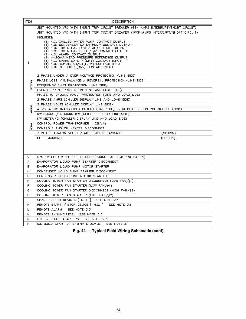
34
Fig. 44 — Typical Field Wiring Schematic (cont)
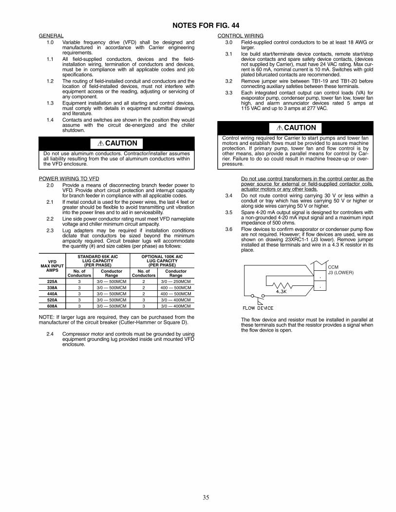
35
NOTES FOR FIG. 44GENERAL
1.0 Variable frequency drive (VFD) shall be designed andmanufactured in accordance with Carrier engineeringrequirements.
1.1 All field-supplied conductors, devices and the field-installation wiring, termination of conductors and devices,must be in compliance with all applicable codes and jobspecifications.
1.2 The routing of field-installed conduit and conductors and thelocation of field-installed devices, must not interfere withequipment access or the reading, adjusting or servicing ofany component.
1.3 Equipment installation and all starting and control devices,must comply with details in equipment submittal drawingsand literature.
1.4 Contacts and switches are shown in the position they wouldassume with the circuit de-energized and the chillershutdown.
POWER WIRING TO VFD2.0 Provide a means of disconnecting branch feeder power to
VFD. Provide short circuit protection and interrupt capacityfor branch feeder in compliance with all applicable codes.
2.1 If metal conduit is used for the power wires, the last 4 feet orgreater should be flexible to avoid transmitting unit vibrationinto the power lines and to aid in serviceability.
2.2 Line side power conductor rating must meet VFD nameplatevoltage and chiller minimum circuit ampacity.
2.3 Lug adapters may be required if installation conditionsdictate that conductors be sized beyond the minimumampacity required. Circuit breaker lugs will accommodatethe quantity (#) and size cables (per phase) as follows:
NOTE: If larger lugs are required, they can be purchased from themanufacturer of the circuit breaker (Cutler-Hammer or Square D).
2.4 Compressor motor and controls must be grounded by usingequipment grounding lug provided inside unit mounted VFDenclosure.
CONTROL WIRING3.0 Field-supplied control conductors to be at least 18 AWG or
larger.3.1 Ice build start/terminate device contacts, remote start/stop
device contacts and spare safety device contacts, (devicesnot supplied by Carrier), must have 24 VAC rating. Max cur-rent is 60 mA, nominal current is 10 mA. Switches with goldplated bifurcated contacts are recommended.
3.2 Remove jumper wire between TB1-19 and TB1-20 beforeconnecting auxiliary safeties between these terminals.
3.3 Each integrated contact output can control loads (VA) forevaporator pump, condenser pump, tower fan low, tower fanhigh, and alarm annunciator devices rated 5 amps at115 VAC and up to 3 amps at 277 VAC.
Do not use control transformers in the control center as thepower source for external or field-supplied contactor coils,actuator motors or any other loads.
3.4 Do not route control wiring carrying 30 V or less within aconduit or tray which has wires carrying 50 V or higher oralong side wires carrying 50 V or higher.
3.5 Spare 4-20 mA output signal is designed for controllers witha non-grounded 4-20 mA input signal and a maximum inputimpedance of 500 ohms.
3.6 Flow devices to confirm evaporator or condenser pump floware not required. However; if flow devices are used, wire asshown on drawing 23XRC1-1 (J3 lower). Remove jumperinstalled at these terminals and wire in a 4.3 K resistor in itsplace.
The flow device and resistor must be installed in parallel atthese terminals such that the resistor provides a signal whenthe flow device is open.
CAUTIONDo not use aluminum conductors. Contractor/installer assumesall liability resulting from the use of aluminum conductors withinthe VFD enclosure.
VFDMAX INPUT
AMPS
STANDARD 65K AIC LUG CAPACITY(PER PHASE)
OPTIONAL 100K AIC LUG CAPACITY(PER PHASE)
No. ofConductors
ConductorRange
No. ofConductors
ConductorRange
225A 3 3/0 — 500MCM 2 3/0 — 250MCM
338A 3 3/0 — 500MCM 2 400 — 500MCM
440A 3 3/0 — 500MCM 2 400 — 500MCM
520A 3 3/0 — 500MCM 3 3/0 — 400MCM
608A 3 3/0 — 500MCM 3 3/0 — 400MCM
CAUTIONControl wiring required for Carrier to start pumps and tower fanmotors and establish flows must be provided to assure machineprotection. If primary pump, tower fan and flow control is byother means, also provide a parallel means for control by Car-rier. Failure to do so could result in machine freeze-up or over-pressure.
CCMJ3 (LOWER)
a23-1587
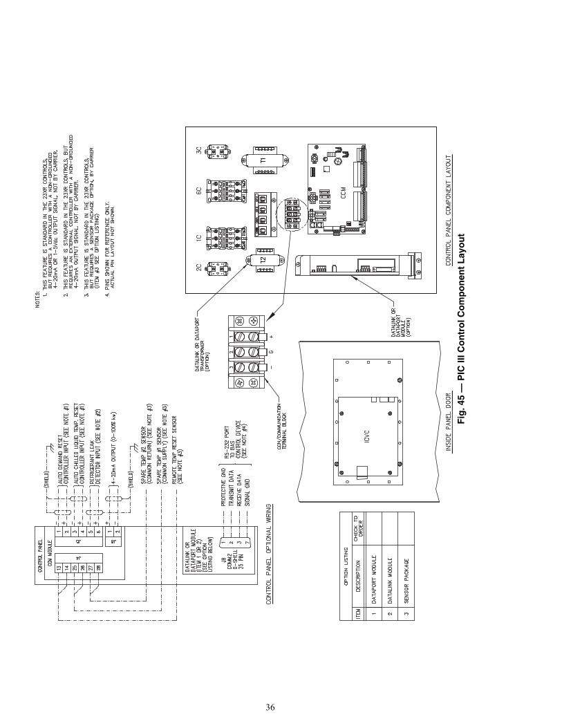
36
Fig
. 45
— P
IC II
I Co
ntr
ol C
om
po
nen
t L
ayo
ut
a23-1584

37
WIRING THE FIELD WIRING TERMINAL STRIPS —This section describes how to wire the field wiring terminalstrips shown in Fig. 46 and 47. The control terminal blocks aremounted to the inside of the enclosure, above and below thecontrol panel.NOTE: Up to 30 v may be measured across open contactterminals on the hazardous voltage terminal strip.
1. Turn off, lock out, and tag the input power to the drive.Wait five minutes.
2. Verify that there is no voltage at the input terminals (L1,L2, and L3) of the power module.
3. Verify that the status LEDs on the CommunicationsInterface Board are not lit. See Fig. 48. The location ofthe Communications Interface Board is shown in Fig. 6.
4. Use a screwdriver to remove conduit twist outs in thecontrol panel. Do not punch holes or drill into the topsurface of the control center enclosure for field wiring.Knockouts are provided in the back of the control centerfor field wiring connections.
5. Connect the control wiring as shown in Fig. 47. Tightenall connections to 7 to 9 in.-lb.
CONNECT CONTROL INPUTS — Wiring may be speci-fied for a spare safety switch, and a remote start/stop contact
can be wired to the starter terminal strip. Additional spare sen-sors and Carrier Comfort Network® modules may be specifiedas well. These are wired to the machine control panel asindicated in Fig. 49.CONNECT CONTROL OUTPUTS — Connect auxiliaryequipment, chilled and condenser water pumps, and sparealarms as required and indicated on job wiring drawings.CONNECT STARTER — The 23XRV chiller is equippedwith a unit-mounted VFD starter (Fig. 50).
Remove the VFD shipping bracket shown in Fig. 16.
IMPORTANT: Be sure to ground the power circuit inaccordance with the National Electrical Code (NEC),applicable local codes, and job wiring diagrams. Also,make sure correct phasing is observed for proper rotation.
CAUTION
Do not punch holes or drill into the top surface of thecontrol center. Knockouts are provided in the back of thecontrol center for wiring connections.
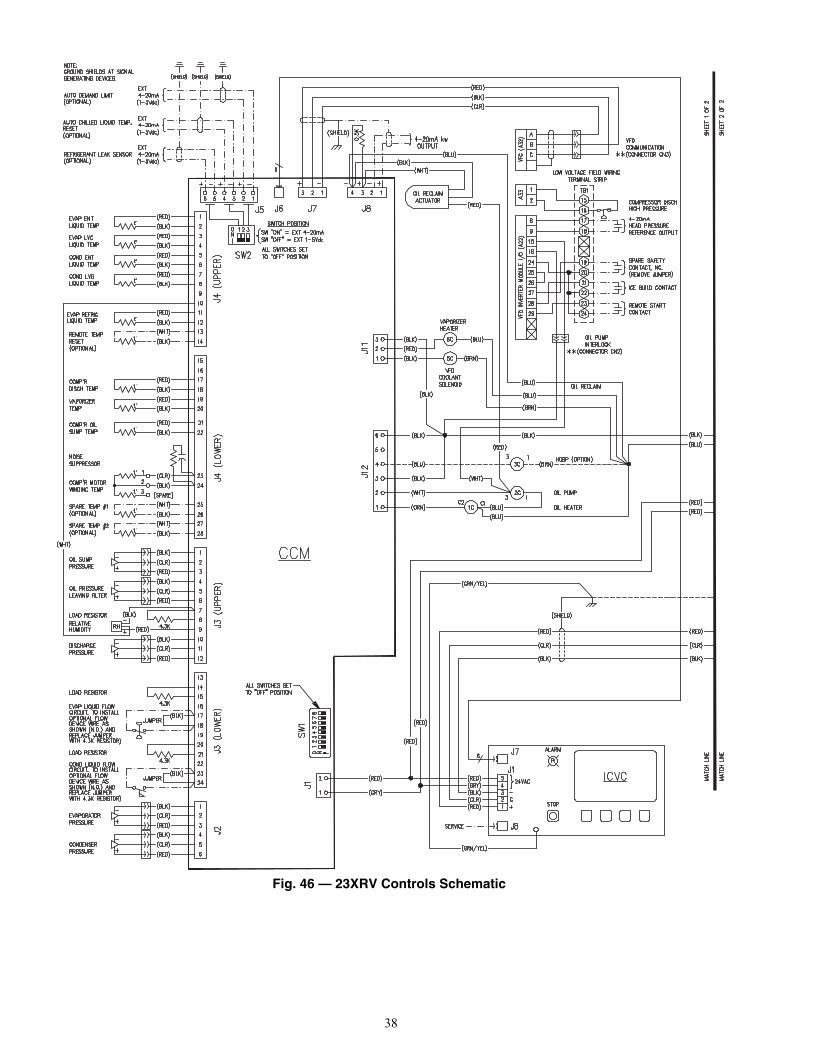
38
Fig. 46 — 23XRV Controls Schematic
a23-1588

39
Fig. 46 — 23XRV Controls Schematic (cont)
a23-1589

40
DPI Communications Interface Board
Status LEDs
Fig. 47 — Control Terminal Blocks
Fig. 48 — Communications Interface Board Status Lights
a23-1590
a23-1591
a23-1592
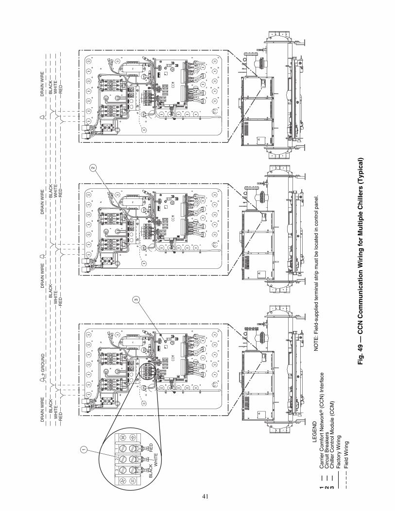
41
DR
AIN
WIR
ED
RA
IN W
IRE
DR
AIN
WIR
ED
RA
IN W
IRE
GR
OU
ND
BLA
CK
WH
ITE
RE
D
BLA
CK
WH
ITE
RE
D
BLA
CK
WH
ITE
RE
D
BLA
CK
WH
ITE
RE
D
1
2
3
RE
DB
LAC
K WH
ITE
Fig
. 49
— C
CN
Co
mm
un
icat
ion
Wir
ing
fo
r M
ult
iple
Ch
iller
s (T
ypic
al)
LE
GE
ND
1—
Car
rier
Com
fort
Net
wor
k® (
CC
N)
Inte
rfac
e2
—C
ircui
t Bre
aker
s3
—C
hille
r C
ontr
ol M
odul
e (C
CM
)Fa
ctor
y W
iring
Fie
ld W
iring
NO
TE
: Fie
ld-s
uppl
ied
term
inal
str
ip m
ust b
e lo
cate
d in
con
trol
pan
el.
a23-1593
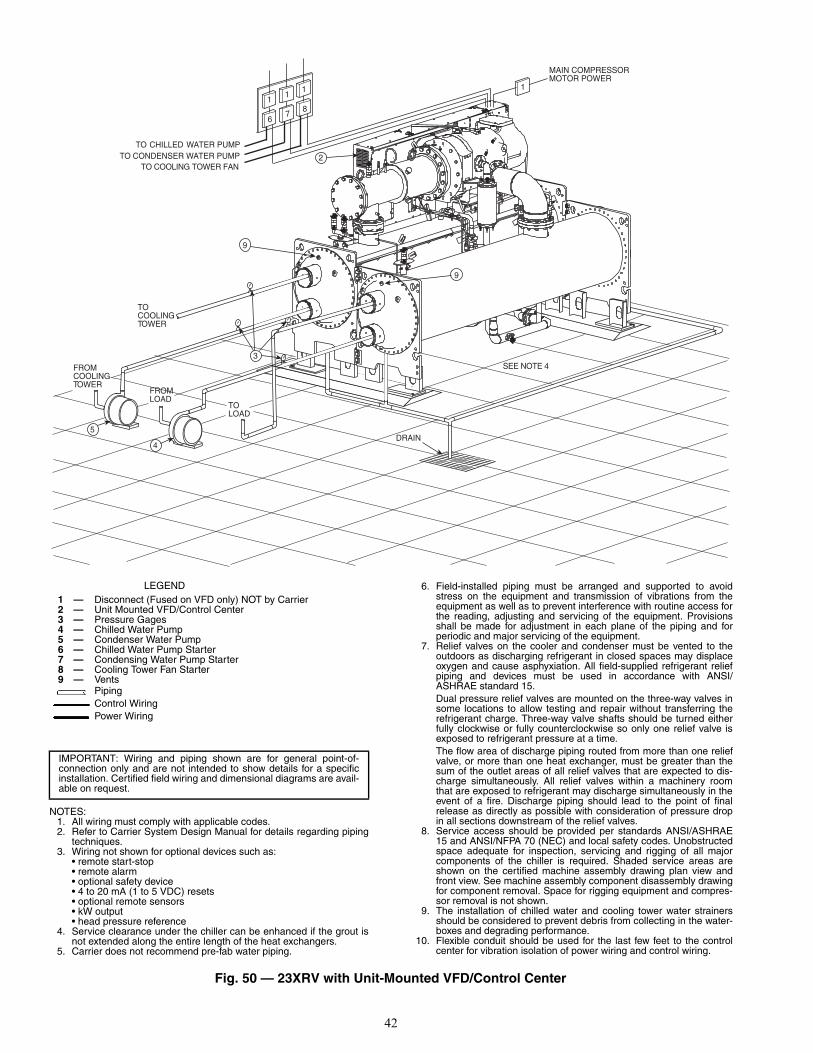
42
TO CHILLED WATER PUMPTO CONDENSER WATER PUMP
TO COOLING TOWER FAN
TOCOOLINGTOWER
FROMCOOLINGTOWER
FROMLOAD
TOLOAD
3
5
4DRAIN
MAIN COMPRESSORMOTOR POWER
1
11
1
2
SEE NOTE 4
67
8
9
9
LEGEND1 — Disconnect (Fused on VFD only) NOT by Carrier2 — Unit Mounted VFD/Control Center3 — Pressure Gages4 — Chilled Water Pump5 — Condenser Water Pump
6 — Chilled Water Pump Starter 7 — Condensing Water Pump Starter 8 — Cooling Tower Fan Starter 9 — Vents
PipingControl WiringPower Wiring
6. Field-installed piping must be arranged and supported to avoidstress on the equipment and transmission of vibrations from theequipment as well as to prevent interference with routine access forthe reading, adjusting and servicing of the equipment. Provisionsshall be made for adjustment in each plane of the piping and forperiodic and major servicing of the equipment.
7. Relief valves on the cooler and condenser must be vented to theoutdoors as discharging refrigerant in closed spaces may displaceoxygen and cause asphyxiation. All field-supplied refrigerant reliefpiping and devices must be used in accordance with ANSI/ASHRAE standard 15.Dual pressure relief valves are mounted on the three-way valves insome locations to allow testing and repair without transferring therefrigerant charge. Three-way valve shafts should be turned eitherfully clockwise or fully counterclockwise so only one relief valve isexposed to refrigerant pressure at a time.The flow area of discharge piping routed from more than one reliefvalve, or more than one heat exchanger, must be greater than thesum of the outlet areas of all relief valves that are expected to dis-charge simultaneously. All relief valves within a machinery roomthat are exposed to refrigerant may discharge simultaneously in theevent of a fire. Discharge piping should lead to the point of finalrelease as directly as possible with consideration of pressure dropin all sections downstream of the relief valves.
8. Service access should be provided per standards ANSI/ASHRAE15 and ANSI/NFPA 70 (NEC) and local safety codes. Unobstructedspace adequate for inspection, servicing and rigging of all majorcomponents of the chiller is required. Shaded service areas areshown on the certified machine assembly drawing plan view andfront view. See machine assembly component disassembly drawingfor component removal. Space for rigging equipment and compres-sor removal is not shown.
9. The installation of chilled water and cooling tower water strainersshould be considered to prevent debris from collecting in the water-boxes and degrading performance.
10. Flexible conduit should be used for the last few feet to the controlcenter for vibration isolation of power wiring and control wiring.
Fig. 50 — 23XRV with Unit-Mounted VFD/Control Center
NOTES:1. All wiring must comply with applicable codes.2. Refer to Carrier System Design Manual for details regarding piping
techniques.3. Wiring not shown for optional devices such as:
• remote start-stop• remote alarm• optional safety device• 4 to 20 mA (1 to 5 VDC) resets• optional remote sensors• kW output• head pressure reference
4. Service clearance under the chiller can be enhanced if the grout isnot extended along the entire length of the heat exchangers.
5. Carrier does not recommend pre-fab water piping.
IMPORTANT: Wiring and piping shown are for general point-of-connection only and are not intended to show details for a specificinstallation. Certified field wiring and dimensional diagrams are avail-able on request.
a23-1594
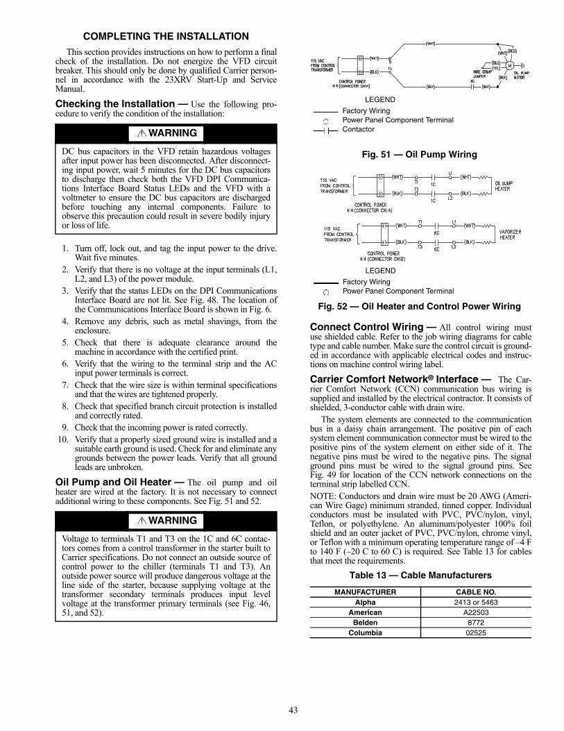
43
COMPLETING THE INSTALLATIONThis section provides instructions on how to perform a final
check of the installation. Do not energize the VFD circuitbreaker. This should only be done by qualified Carrier person-nel in accordance with the 23XRV Start-Up and ServiceManual.
Checking the Installation — Use the following pro-cedure to verify the condition of the installation:
1. Turn off, lock out, and tag the input power to the drive.Wait five minutes.
2. Verify that there is no voltage at the input terminals (L1,L2, and L3) of the power module.
3. Verify that the status LEDs on the DPI CommunicationsInterface Board are not lit. See Fig. 48. The location ofthe Communications Interface Board is shown in Fig. 6.
4. Remove any debris, such as metal shavings, from theenclosure.
5. Check that there is adequate clearance around themachine in accordance with the certified print.
6. Verify that the wiring to the terminal strip and the ACinput power terminals is correct.
7. Check that the wire size is within terminal specificationsand that the wires are tightened properly.
8. Check that specified branch circuit protection is installedand correctly rated.
9. Check that the incoming power is rated correctly.10. Verify that a properly sized ground wire is installed and a
suitable earth ground is used. Check for and eliminate anygrounds between the power leads. Verify that all groundleads are unbroken.
Oil Pump and Oil Heater — The oil pump and oilheater are wired at the factory. It is not necessary to connectadditional wiring to these components. See Fig. 51 and 52.
Connect Control Wiring — All control wiring mustuse shielded cable. Refer to the job wiring diagrams for cabletype and cable number. Make sure the control circuit is ground-ed in accordance with applicable electrical codes and instruc-tions on machine control wiring label.
Carrier Comfort Network® Interface — The Car-rier Comfort Network (CCN) communication bus wiring issupplied and installed by the electrical contractor. It consists ofshielded, 3-conductor cable with drain wire.
The system elements are connected to the communicationbus in a daisy chain arrangement. The positive pin of eachsystem element communication connector must be wired to thepositive pins of the system element on either side of it. Thenegative pins must be wired to the negative pins. The signalground pins must be wired to the signal ground pins. SeeFig. 49 for location of the CCN network connections on theterminal strip labelled CCN.NOTE: Conductors and drain wire must be 20 AWG (Ameri-can Wire Gage) minimum stranded, tinned copper. Individualconductors must be insulated with PVC, PVC/nylon, vinyl,Teflon, or polyethylene. An aluminum/polyester 100% foilshield and an outer jacket of PVC, PVC/nylon, chrome vinyl,or Teflon with a minimum operating temperature range of –4 Fto 140 F (–20 C to 60 C) is required. See Table 13 for cablesthat meet the requirements.
Table 13 — Cable Manufacturers
WARNING
DC bus capacitors in the VFD retain hazardous voltagesafter input power has been disconnected. After disconnect-ing input power, wait 5 minutes for the DC bus capacitorsto discharge then check both the VFD DPI Communica-tions Interface Board Status LEDs and the VFD with avoltmeter to ensure the DC bus capacitors are dischargedbefore touching any internal components. Failure toobserve this precaution could result in severe bodily injuryor loss of life.
WARNING
Voltage to terminals T1 and T3 on the 1C and 6C contac-tors comes from a control transformer in the starter built toCarrier specifications. Do not connect an outside source ofcontrol power to the chiller (terminals T1 and T3). Anoutside power source will produce dangerous voltage at theline side of the starter, because supplying voltage at thetransformer secondary terminals produces input levelvoltage at the transformer primary terminals (see Fig. 46,51, and 52).
MANUFACTURER CABLE NO.Alpha 2413 or 5463
American A22503Belden 8772
Columbia 02525
LEGEND
Factory WiringPower Panel Component TerminalContactor
Fig. 51 — Oil Pump Wiring
Fig. 52 — Oil Heater and Control Power Wiring
LEGEND
Factory WiringPower Panel Component Terminal
a23-1595
a23-1596
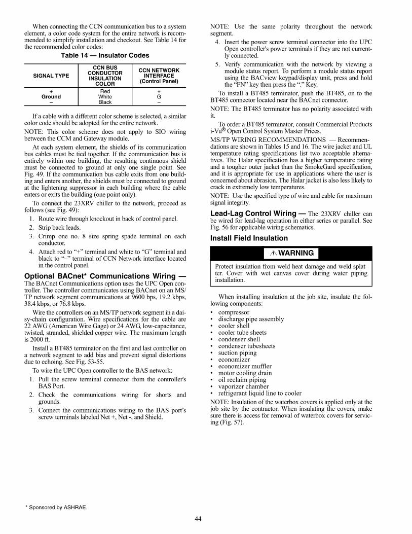
44
When connecting the CCN communication bus to a systemelement, a color code system for the entire network is recom-mended to simplify installation and checkout. See Table 14 forthe recommended color codes:
Table 14 — Insulator Codes
If a cable with a different color scheme is selected, a similarcolor code should be adopted for the entire network.NOTE: This color scheme does not apply to SIO wiringbetween the CCM and Gateway module.
At each system element, the shields of its communicationbus cables must be tied together. If the communication bus isentirely within one building, the resulting continuous shieldmust be connected to ground at only one single point. SeeFig. 49. If the communication bus cable exits from one build-ing and enters another, the shields must be connected to groundat the lightening suppressor in each building where the cableenters or exits the building (one point only).
To connect the 23XRV chiller to the network, proceed asfollows (see Fig. 49):
1. Route wire through knockout in back of control panel.2. Strip back leads.3. Crimp one no. 8 size spring spade terminal on each
conductor.4. Attach red to “+” terminal and white to “G” terminal and
black to “–” terminal of CCN Network interface locatedin the control panel.
Optional BACnet* Communications Wiring —The BACnet Communications option uses the UPC Open con-troller. The controller communicates using BACnet on an MS/TP network segment communications at 9600 bps, 19.2 kbps,38.4 kbps, or 76.8 kbps.
Wire the controllers on an MS/TP network segment in a dai-sy-chain configuration. Wire specifications for the cable are22 AWG (American Wire Gage) or 24 AWG, low-capacitance,twisted, stranded, shielded copper wire. The maximum lengthis 2000 ft.
Install a BT485 terminator on the first and last controller ona network segment to add bias and prevent signal distortionsdue to echoing. See Fig. 53-55.
To wire the UPC Open controller to the BAS network:1. Pull the screw terminal connector from the controller's
BAS Port.2. Check the communications wiring for shorts and
grounds.3. Connect the communications wiring to the BAS port’s
screw terminals labeled Net +, Net -, and Shield.
NOTE: Use the same polarity throughout the networksegment.
4. Insert the power screw terminal connector into the UPCOpen controller's power terminals if they are not current-ly connected.
5. Verify communication with the network by viewing amodule status report. To perform a module status reportusing the BACview keypad/display unit, press and holdthe “FN” key then press the “.” Key.
To install a BT485 terminator, push the BT485, on to theBT485 connector located near the BACnet connector.NOTE: The BT485 terminator has no polarity associated withit.
To order a BT485 terminator, consult Commercial Productsi-Vu® Open Control System Master Prices.MS/TP WIRING RECOMMENDATIONS — Recommen-dations are shown in Tables 15 and 16. The wire jacket and ULtemperature rating specifications list two acceptable alterna-tives. The Halar specification has a higher temperature ratingand a tougher outer jacket than the SmokeGard specification,and it is appropriate for use in applications where the user isconcerned about abrasion. The Halar jacket is also less likely tocrack in extremely low temperatures. NOTE: Use the specified type of wire and cable for maximumsignal integrity.
Lead-Lag Control Wiring — The 23XRV chiller canbe wired for lead-lag operation in either series or parallel. SeeFig. 56 for applicable wiring schematics.
Install Field Insulation
When installing insulation at the job site, insulate the fol-lowing components:• compressor• discharge pipe assembly• cooler shell• cooler tube sheets• condenser shell• condenser tubesheets• suction piping• economizer• economizer muffler• motor cooling drain • oil reclaim piping• vaporizer chamber• refrigerant liquid line to coolerNOTE: Insulation of the waterbox covers is applied only at thejob site by the contractor. When insulating the covers, makesure there is access for removal of waterbox covers for servic-ing (Fig. 57).
SIGNAL TYPE
CCN BUS CONDUCTORINSULATION
COLOR
CCN NETWORKINTERFACE
(Control Panel)
+ Red +Ground White G
– Black –
WARNING
Protect insulation from weld heat damage and weld splat-ter. Cover with wet canvas cover during water pipinginstallation.
* Sponsored by ASHRAE.
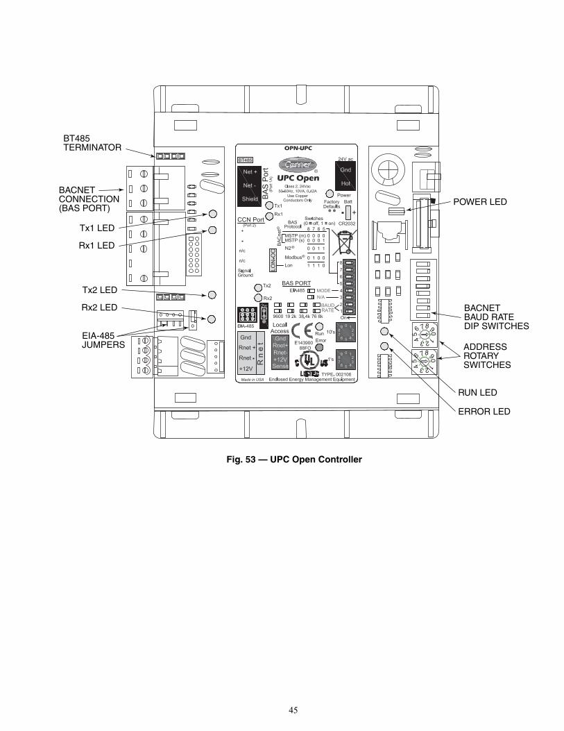
45
Fig. 53 — UPC Open Controller
876
54 321
09
876
54 321
09
BACNETBAUD RATEDIP SWITCHES
ADDRESSROTARYSWITCHES
POWER LED
RUN LED
ERROR LED
BACNETCONNECTION(BAS PORT)
BT485TERMINATOR
Tx2 LED
Rx2 LED
Tx1 LED
Rx1 LED
EIA-485JUMPERS
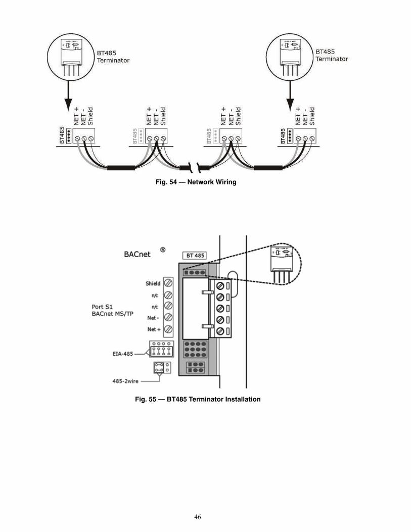
46
Fig. 54 — Network Wiring
Fig. 55 — BT485 Terminator Installation
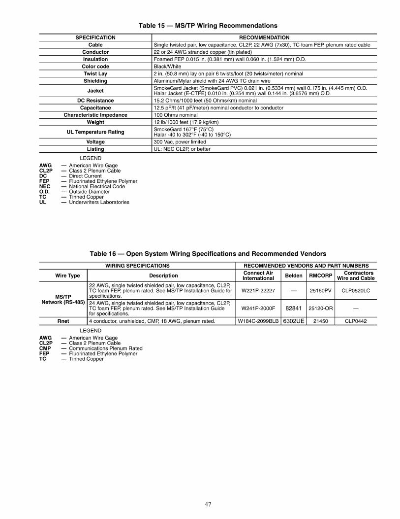
47
Table 15 — MS/TP Wiring Recommendations
LEGEND
Table 16 — Open System Wiring Specifications and Recommended Vendors
LEGEND
SPECIFICATION RECOMMENDATIONCable Single twisted pair, low capacitance, CL2P, 22 AWG (7x30), TC foam FEP, plenum rated cable
Conductor 22 or 24 AWG stranded copper (tin plated) Insulation Foamed FEP 0.015 in. (0.381 mm) wall 0.060 in. (1.524 mm) O.D. Color code Black/White Twist Lay 2 in. (50.8 mm) lay on pair 6 twists/foot (20 twists/meter) nominal Shielding Aluminum/Mylar shield with 24 AWG TC drain wire
Jacket SmokeGard Jacket (SmokeGard PVC) 0.021 in. (0.5334 mm) wall 0.175 in. (4.445 mm) O.D. Halar Jacket (E-CTFE) 0.010 in. (0.254 mm) wall 0.144 in. (3.6576 mm) O.D.
DC Resistance 15.2 Ohms/1000 feet (50 Ohms/km) nominal Capacitance 12.5 pF/ft (41 pF/meter) nominal conductor to conductor
Characteristic Impedance 100 Ohms nominal Weight 12 lb/1000 feet (17.9 kg/km)
UL Temperature Rating SmokeGard 167°F (75°C) Halar -40 to 302°F (-40 to 150°C)
Voltage 300 Vac, power limited Listing UL: NEC CL2P, or better
AWG — American Wire GageCL2P — Class 2 Plenum CableDC — Direct CurrentFEP — Fluorinated Ethylene PolymerNEC — National Electrical CodeO.D. — Outside DiameterTC — Tinned CopperUL — Underwriters Laboratories
WIRING SPECIFICATIONS RECOMMENDED VENDORS AND PART NUMBERS
Wire Type Description Connect AirInternational Belden RMCORP Contractors
Wire and Cable
MS/TPNetwork (RS-485)
22 AWG, single twisted shielded pair, low capacitance, CL2P, TC foam FEP, plenum rated. See MS/TP Installation Guide for specifications.
W221P-22227 — 25160PV CLP0520LC
24 AWG, single twisted shielded pair, low capacitance, CL2P, TC foam FEP, plenum rated. See MS/TP Installation Guidefor specifications.
W241P-2000F 82841 25120-OR —
Rnet 4 conductor, unshielded, CMP, 18 AWG, plenum rated. W184C-2099BLB 6302UE 21450 CLP0442
AWG — American Wire GageCL2P — Class 2 Plenum CableCMP — Communications Plenum RatedFEP — Fluorinated Ethylene PolymerTC — Tinned Copper

48
Fig
. 56
— L
ead
/Lag
Co
ntr
ol W
irin
g
a23-1597
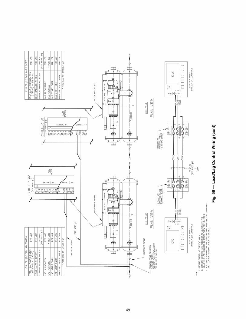
49
Fig
. 56
— L
ead
/Lag
Co
ntr
ol W
irin
g (
con
t)
a23-1598
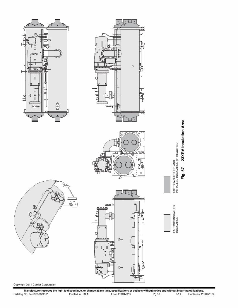
Manufacturer reserves the right to discontinue, or change at any time, specifications or designs without notice and without incurring obligations.Catalog No. 04-53230002-01 Printed in U.S.A. Form 23XRV-2SI Pg 50 2-11 Replaces: 23XRV-1SI
Copyright 2011 Carrier Corporation
FAC
TOR
Y-IN
STA
LLE
DIN
SU
LAT
ION
FAC
TOR
Y-S
UP
PLI
ED
AN
DIN
STA
LLE
D IN
SU
LAT
ION
(IF
RE
QU
IRE
D)
Fig
. 57
— 2
3XR
V In
sula
tio
n A
rea

CL-1
INSTALLATION START-UP REQUEST CHECKLIST
Machine Model Number: 23XRV Serial Number:
To:
Attn.:
Date
Project Name
Carrier Job Number
The following information provides the status of the chiller installation. Send a copy of this checklist to the local Carrier Service officeafter it has been completed and signed-off by the Purchaser and Job Site Supervisor.
YES/NO DATE TO BE(N/A) COMPLETED
1. The machine is level within 1/2 in. end to end.2. The machine components are installed and connected in
accordance with the installation instructions.3. The isolation package and grouting (if necessary)
are installed.4. The relief valves are piped to the atmosphere.5. All piping is installed and supported. Direction of flow
is indicated in accordance with the installation instructionsand job prints.a. Chilled water pipingb. Condenser water pipingc. Waterbox drain pipingd. Pumpout unit condenser piping (if installed)e. Other
6. Gages are installed as called for on the job prints requiredto establish design flow for the cooler and condenser.a. Water pressure gages IN and OUTb. Water temperature gages IN and OUT
7. The machine’s control center wiring is complete. The wiring isinstalled per installation instructions and certified prints.a. Power wiring to VFD circuit breaker. (If chiller was disassembled during installation, motor leads must
not be taped until the Carrier technician megger teststhe motor.)
b. Carrier controls can independently energize water pumps and tower fan.
c. Line side voltage is within ±10% of chiller nameplate voltage.d. Other
COMMENTS:
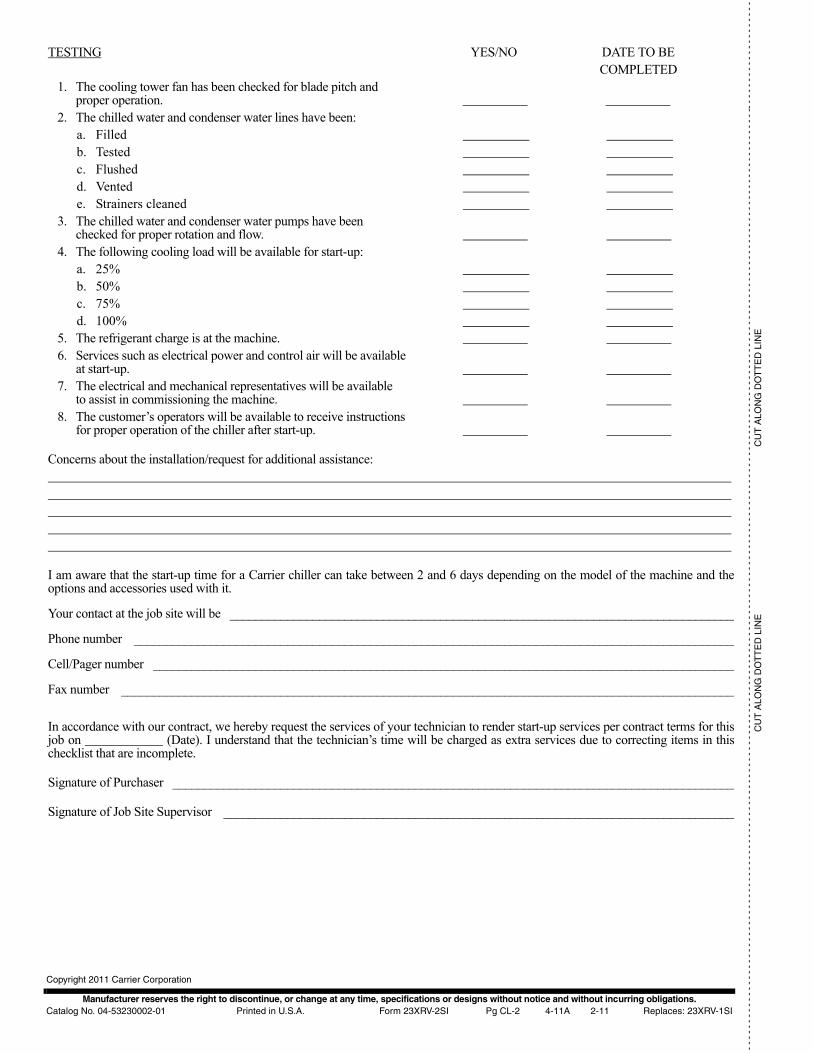
Manufacturer reserves the right to discontinue, or change at any time, specifications or designs without notice and without incurring obligations.Catalog No. 04-53230002-01 Printed in U.S.A. Form 23XRV-2SI Pg CL-2 4-11A 2-11 Replaces: 23XRV-1SI
Copyright 2011 Carrier Corporation
- -
- -
- -
- -
- -
- -
- -
- -
- -
- -
- -
- -
- -
- -
- -
- -
- -
- -
- -
- -
- -
- -
- -
- -
- -
- -
- -
- -
- -
- -
- -
- -
- -
- -
- -
- -
- -
- -
- -
- -
- -
- -
- -
- -
- -
- -
- -
- -
- -
- -
- -
- -
- -
- -
- -
- -
- -
- -
- -
- -
- -
- -
- -
- -
- -
- -
- -
- -
- -
- -
- -
- -
- -
- -
- -
- -
- -
- -
- -
- -
- -
- -
- -
- -
- -
- -
- --
- -
- -
- -
- -
- -
- -
- -
- -
- -
-
CU
T A
LON
G D
OT
TE
D L
INE
CU
T A
LON
G D
OT
TE
D L
INE
TESTING YES/NO DATE TO BECOMPLETED
1. The cooling tower fan has been checked for blade pitch andproper operation.
2. The chilled water and condenser water lines have been:a. Filledb. Testedc. Flushedd. Ventede. Strainers cleaned
3. The chilled water and condenser water pumps have beenchecked for proper rotation and flow.
4. The following cooling load will be available for start-up:a. 25%b. 50%c. 75%d. 100%
5. The refrigerant charge is at the machine.6. Services such as electrical power and control air will be available
at start-up.7. The electrical and mechanical representatives will be available
to assist in commissioning the machine.8. The customer’s operators will be available to receive instructions
for proper operation of the chiller after start-up.
Concerns about the installation/request for additional assistance:
I am aware that the start-up time for a Carrier chiller can take between 2 and 6 days depending on the model of the machine and theoptions and accessories used with it.
Your contact at the job site will be _______________________________________________________________________________
Phone number ______________________________________________________________________________________________
Cell/Pager number ___________________________________________________________________________________________
Fax number ________________________________________________________________________________________________
In accordance with our contract, we hereby request the services of your technician to render start-up services per contract terms for thisjob on (Date). I understand that the technician’s time will be charged as extra services due to correcting items in thischecklist that are incomplete.
Signature of Purchaser ________________________________________________________________________________________
Signature of Job Site Supervisor ________________________________________________________________________________


