
Enterprise and Datacenter SSD Form Factor - 1U Short Specification 0.9 Draft
1
Enterprise and Datacenter
SSD Form Factor
1U Short Specification
Revision 0.9 Draft
October 27, 2017
Enterprise and Datacenter SSD Form Factor Working Group
Please send comments to Anthony Constantine

Enterprise and Datacenter SSD Form Factor - 1U Short Specification 0.9 Draft
2
Abstract: This specification defines the mechanical attributes of a 1U short form factor for a solid state
drive that will fit in 1U rack mounted host systems designed to support this new form factor.
This specification provides a common reference for host systems manufacturers, host system integrators, and device suppliers. This specification originates from Enterprise and Datacenter SSD Form Factor Working Group (EDSFF).
The description of the device in this specification does not assure that the specific component is actually available from device suppliers. If such a device is supplied it must comply with this specification to achieve interoperability between device suppliers.
INTELLECTUAL PROPERTY DISCLAIMER THIS DRAFT VERSION OF THE SPECIFICATION IS PROVIDED “AS IS” WITH NO WARRANTIES WHATSOEVER INCLUDING ANY WARRANTY OF MERCHANTABILITY, FITNESS FOR ANY PARTICULAR PURPOSE, OR ANY WARRANTY OTHERWISE ARISING OUT OF ANY PROPOSAL, SPECIFICATION, OR SAMPLE.
THIS DRAFT VERSION OF THE SPECIFICATION IS PROVIDED FOR INFORMATIONAL PURPOSES ONLY AND NO LICENSE, EXPRESS OR IMPLIED, BY ESTOPPEL OR OTHERWISE, TO ANY INTELLECTUAL PROPERTY RIGHTS IS GRANTED OR INTENDED HEREBY.
THE ENTERPRISE AND DATACENTER SSD FORM FACTOR WORKGROUP AND EACH INDIVIDUAL MEMBER THEREOF DISCLAIMS ALL LIABILITY, INCLUDING LIABILITY FOR INFRINGEMENT OF PROPRIETARY RIGHTS, RELATING TO IMPLEMENTATION OF INFORMATION IN THIS SPECIFICATION. THE ENTERPRISE AND DATACENTER SSD FORM FACTOR WORKGROUP DOES NOT WARRANT OR REPRESENT THAT SUCH IMPLEMENTATION(S) WILL NOT INFRINGE SUCH RIGHTS.

Enterprise and Datacenter SSD Form Factor - 1U Short Specification 0.9 Draft
3
Revision History
Rev History Date
0.9 Draft spec

Enterprise and Datacenter SSD Form Factor - 1U Short Specification 0.9 Draft
4
Table of Contents
1 SCOPE ...................................................................................................................... 5
1.1 Goal ........................................................................................................................................................... 5
2 REFERENCES ............................................................................................................. 6
2.1 Specification References ........................................................................................................................... 6
2.2 Keywords ................................................................................................................................................... 6
2.3 Terms and Definitions ................................................................................................................................ 6
3 GENERAL DESCRIPTION ............................................................................................... 7
4 PHYSICAL DEFINITION: 1U SHORT FORM FACTOR ........................................................... 8
6 INFORMATIVE: SFF-TA-1002 EDGE (PLUG) MECHANICAL DRAWING ................................. 12

Enterprise and Datacenter SSD Form Factor - 1U Short Specification 0.9 Draft
5
1 Scope
This specification defines the mechanical attributes of a new form factor for a solid state drive that will fit in 1U rack mounted host systems designed to support this form factor.
1.1 Goal
This 1U short form factor provides external dimensions, card edge placement, grounded mechanical mounting hole locations and LED placement to assist host system manufacturers in integration of this form factor.
The environment for the 1U short form factor is an enclosure connecting one or more drives in a restricted packaging environment.
Enterprise and Datacenter SSD Form Factor - 1U Short Specification 0.9 Draft
6
2 References
2.1 Specification References
ASME Y14.5-2009 Dimensioning and Tolerancing published by ASME
SNIA SFF-TA-1002 Protocol Agnostic Multi-Lane High Speed Connector specification available at http://www.snia.org.
2.2 Keywords
2.2.1 Mandatory: Indicates items to be implemented as defined by this specification
2.2.2 May: Indicates flexibility of choice with no implied preference
2.2.3 Optional: Describes features that are not required by this specification. However, if any optional feature defined by the specification is implemented, the feature shall be implemented in the way defined by the specification.
2.2.4 Reserved: Refers to bits, bytes, words, fields, and opcode values that are set-aside for future standardization. Their use and interpretation may be specified by future extensions to this or other specifications. A reserved bit, byte, word, field, or register shall be cleared to zero, or in accordance with a future extension to this specification. The recipient is not required to check reserved bits, bytes, words, or fields. Receipt of reserved coded values in defined fields in commands shall be reported as an error. Writing a reserved coded value into a controller register field produces undefined results.
2.2.5 Shall: Indicates a mandatory requirement. Designers are required to implement all such mandatory requirements to ensure interoperability with other products that conform to the specification.
2.2.6 Should: Indicates flexibility of choice with a strongly preferred alternative. Equivalent to the phrase “it is recommended”.
2.3 Terms and Definitions
2.3.1 Host: Refers to the interface source or master
2.3.2 Device: Refers to the interface slave
2.3.3 Card: Refers to the device plugged into a connector
2.3.4 1U: 1 Standard Unit or Rack Unit 44.50 mm (1.752 inches).
2.3.5 NVM: Acronym for Non-Volatile Memory
2.3.6 SSD: Acronym for Solid State Drive
2.3.7 Thickness: Form factor dimension including PCB thickness, z-height of all components plus mechanicals.
Enterprise and Datacenter SSD Form Factor - 1U Short Specification 0.9 Draft
7
3 General Description
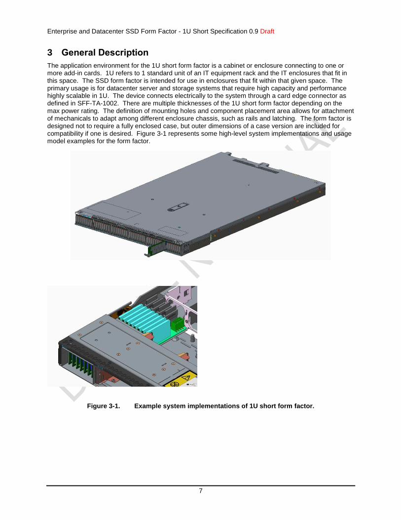
The application environment for the 1U short form factor is a cabinet or enclosure connecting to one or more add-in cards. 1U refers to 1 standard unit of an IT equipment rack and the IT enclosures that fit in this space. The SSD form factor is intended for use in enclosures that fit within that given space. The primary usage is for datacenter server and storage systems that require high capacity and performance highly scalable in 1U. The device connects electrically to the system through a card edge connector as defined in SFF-TA-1002. There are multiple thicknesses of the 1U short form factor depending on the max power rating. The definition of mounting holes and component placement area allows for attachment of mechanicals to adapt among different enclosure chassis, such as rails and latching. The form factor is designed not to require a fully enclosed case, but outer dimensions of a case version are included for compatibility if one is desired. Figure 3-1 represents some high-level system implementations and usage model examples for the form factor.
Figure 3-1. Example system implementations of 1U short form factor.
Enterprise and Datacenter SSD Form Factor - 1U Short Specification 0.9 Draft
8
4 Physical Definition: 1U Short Form Factor
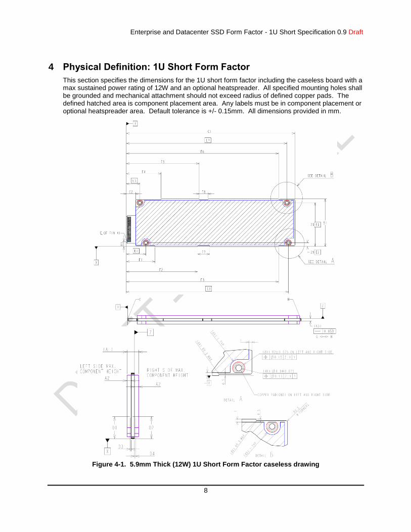
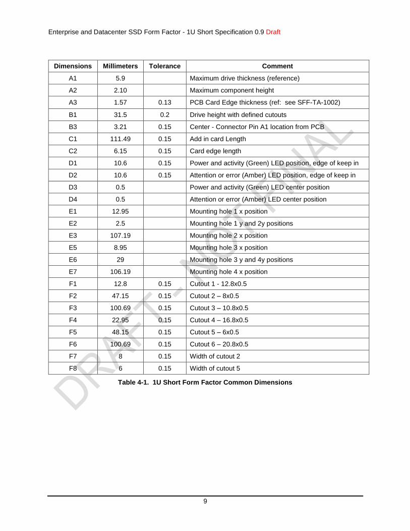
This section specifies the dimensions for the 1U short form factor including the caseless board with a max sustained power rating of 12W and an optional heatspreader. All specified mounting holes shall be grounded and mechanical attachment should not exceed radius of defined copper pads. The defined hatched area is component placement area. Any labels must be in component placement or optional heatspreader area. Default tolerance is +/- 0.15mm. All dimensions provided in mm.
Figure 4-1. 5.9mm Thick (12W) 1U Short Form Factor caseless drawing
Enterprise and Datacenter SSD Form Factor - 1U Short Specification 0.9 Draft
9
Dimensions Millimeters Tolerance Comment
A1 5.9 Maximum drive thickness (reference)
A2 2.10 Maximum component height
A3 1.57 0.13 PCB Card Edge thickness (ref: see SFF-TA-1002)
B1 31.5 0.2 Drive height with defined cutouts
B3 3.21 0.15 Center - Connector Pin A1 location from PCB
C1 111.49 0.15 Add in card Length
C2 6.15 0.15 Card edge length
D1 10.6 0.15 Power and activity (Green) LED position, edge of keep in
D2 10.6 0.15 Attention or error (Amber) LED position, edge of keep in
D3 0.5 Power and activity (Green) LED center position
D4 0.5 Attention or error (Amber) LED center position
E1 12.95 Mounting hole 1 x position
E2 2.5 Mounting hole 1 y and 2y positions
E3 107.19 Mounting hole 2 x position
E5 8.95 Mounting hole 3 x position
E6 29 Mounting hole 3 y and 4y positions
E7 106.19 Mounting hole 4 x position
F1 12.8 0.15 Cutout 1 - 12.8x0.5
F2 47.15 0.15 Cutout 2 – 8x0.5
F3 100.69 0.15 Cutout 3 – 10.8x0.5
F4 22.95 0.15 Cutout 4 – 16.8x0.5
F5 48.15 0.15 Cutout 5 – 6x0.5
F6 100.69 0.15 Cutout 6 – 20.8x0.5
F7 8 0.15 Width of cutout 2
F8 6 0.15 Width of cutout 5
Table 4-1. 1U Short Form Factor Common Dimensions
Enterprise and Datacenter SSD Form Factor - 1U Short Specification 0.9 Draft
10
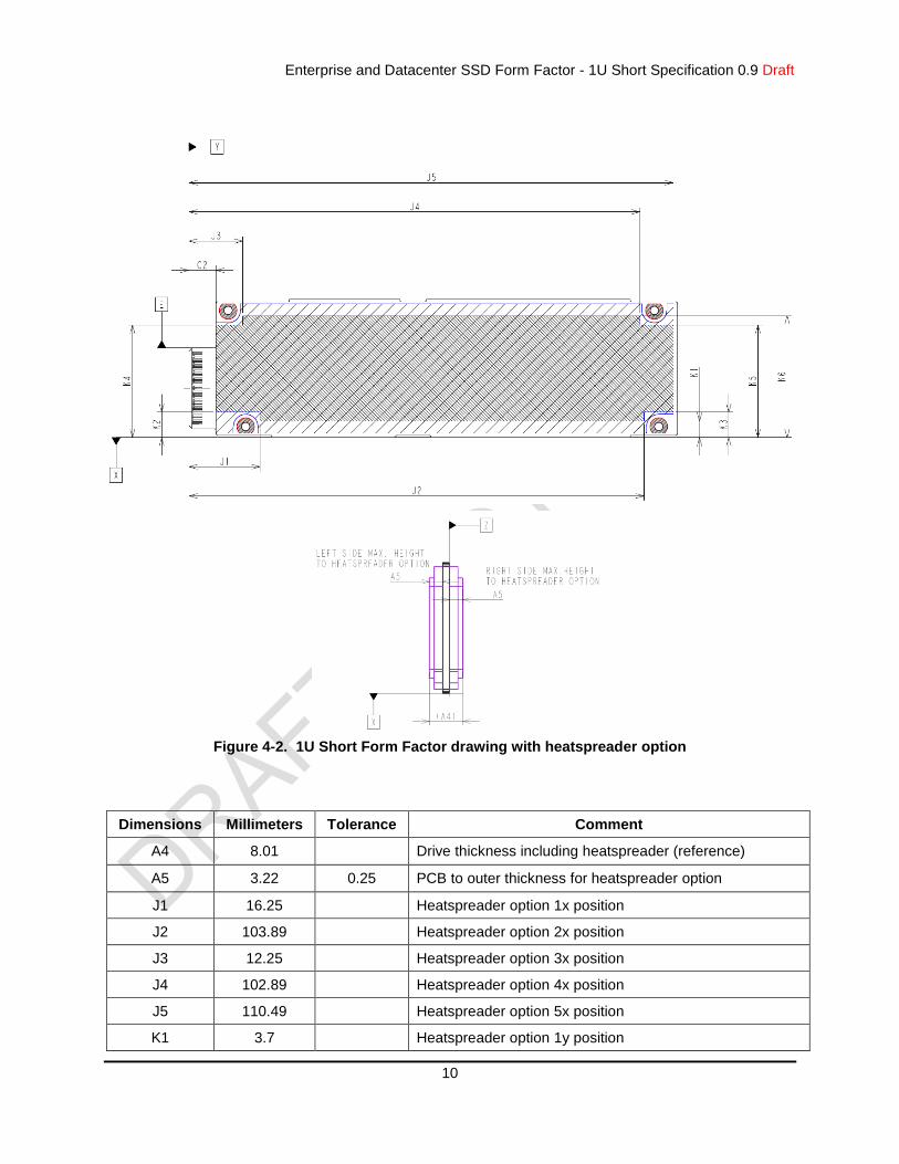
Figure 4-2. 1U Short Form Factor drawing with heatspreader option
Dimensions Millimeters Tolerance Comment
A4 8.01 Drive thickness including heatspreader (reference)
A5 3.22 0.25 PCB to outer thickness for heatspreader option
J1 16.25 Heatspreader option 1x position
J2 103.89 Heatspreader option 2x position
J3 12.25 Heatspreader option 3x position
J4 102.89 Heatspreader option 4x position
J5 110.49 Heatspreader option 5x position
K1 3.7 Heatspreader option 1y position
Enterprise and Datacenter SSD Form Factor - 1U Short Specification 0.9 Draft
11
K2 5.8 Heatspreader option 2y position
K3 5.8 Heatspreader option 3y position
K4 25.7 Heatspreader option 4y position
K5 25.7 Heatspreader option 5y position
K6 27.8 Heatspreader option 6y position
Table 4-2. 1U Short Form Factor – Optional Heatspreader Dimensions
Enterprise and Datacenter SSD Form Factor - 1U Short Specification 0.9 Draft
12
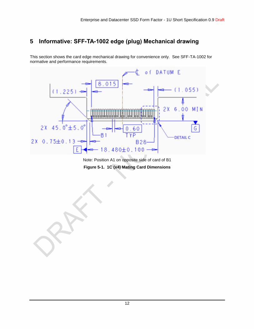
5 Informative: SFF-TA-1002 edge (plug) Mechanical drawing
This section shows the card edge mechanical drawing for convenience only. See SFF-TA-1002 for normative and performance requirements.
Note: Position A1 on opposite side of card of B1
Figure 5-1. 1C (x4) Mating Card Dimensions


