
END

PRESENTATION CONTENTS
• THESIS TILTLE (1)• PRESENTATION CONTENTS (1)• INTRODUCTION (2)• DESIGN PROCEDURES (2)• DESIGN SPECIFICATION (1)• DESIGN FACTOR (5)• SOFTWARE FLOWCHARTS (17)• SOFTWARE DESIGN EXAMPLE (6)• PRESENTATION END
END

OPTICAL FIBER SYSTEM DESIGNINTRODUCTION
• Advantages of Optical Fiber Communication– Extremely wide system bandwidth (LED provides more than
100MHz of BW, while LASER can deliver up to 10GHz).
– Small size and weigh (human hair)
– immunity to electromagnetic interference and cross talk.
– Signal security
– Low signal attenuation (compared to copper conductors)
– unlimited supply (sand is the source of the optical fiber)
– Reduced cost
– Safety (no spark hazard or short circuit)
END

OPTICAL FIBER SYSTEM DESIGNINTRODUCTION
• The Optical Fiber Communication System Components– The optical fiber system consists of three components :
• Transmitter • Optical fiber Link• Receiver
– The Transmitter converts the input electric signal into an optical signal.– The Fiber Link carries the light signal and submit it to the receiver– The Receiver converts the optical signal back to it original form.
END

OPTICAL FIBER SYSTEM DESIGNDESIGN PROCEDURES
• GRAPH AND CHART ASSISTED DESIGN
This devised method is easy way to design an optical fiber system. However, this method is limited in use, since the it is applicable only to the system components made by the manufacture by whom those graphs and charts have been devised.
• FLOWCHART ASSISTED DESIGN
This design method has been devised by some authors, the flowcharts are useful and can be utilized as a guide to the design of each subsystem independently of others. However, a major drawback of those flowcharts is that some of the design parameters in one subsystem are dependent on parameters in another subsystem. As an example, the selection of the spectral width and wavelength for the source affects the the dispersion and the attenuation of the fiber link as well as the spectral response of the detector.
END

OPTICAL FIBER SYSTEM DESIGNDESIGN PROCEDURES
• COMEREHENSIVE FLOWCHARTTo override the mentioned drawbacks of the devised design procedures, a comprehensive flowchart is developed here to cover all the subsystems design considering most system parameters.
• SUB-SYSTEM FLOWCHARTSIn addition, separated subsystem flowcharts are developed to allow the designer to design any part of the system alone.
• COMPUTER PROGRAM
These flowcharts are implemented into a computer program where iterative processes are executed to reach to the best design combination according to predefined design parameters such as performance and cost.
END

OPTICAL FIBER SYSTEM DESIGNDESIGN SPECIFICATION
• The usual specifications given to an optical fiber link designer are
• Data Rate (bit rate),
• Link Length, and
• Bit Error Rate (BER).
Once these requirements are given, the designer must try various combination
of the optical source, fiber, and detector to meet the power budget, bandwidth
budget, and cost budget.
END
OPTICAL FIBER SYSTEM DESIGNDESIGN FACTORS
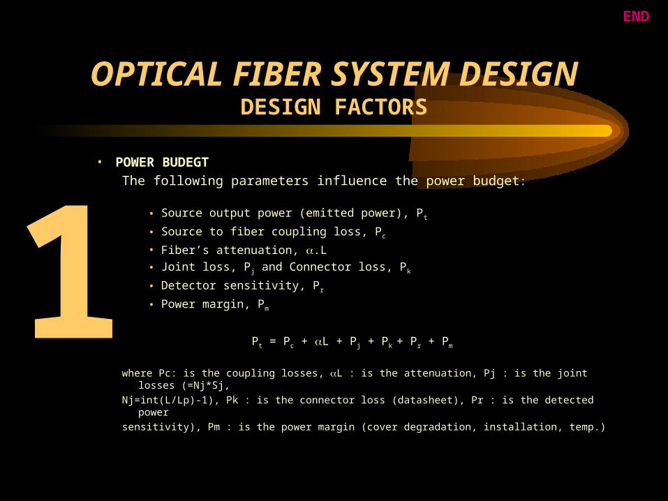
• POWER BUDEGT
The following parameters influence the power budget:
• Source output power (emitted power), Pt
• Source to fiber coupling loss, Pc
• Fiber’s attenuation, .L
• Joint loss, Pj and Connector loss, Pk
• Detector sensitivity, Pr
• Power margin, Pm
Pt = Pc + L + Pj + Pk + Pr + Pm
where Pc: is the coupling losses, L : is the attenuation, Pj : is the joint losses (=Nj*Sj,
Nj=int(L/Lp)-1), Pk : is the connector loss (datasheet), Pr : is the detected power
sensitivity), Pm : is the power margin (cover degradation, installation, temp.)
1
END

OPTICAL FIBER SYSTEM DESIGNDESIGN FACTORS
• BANDWIDTH BUDEGT
The Bandwidth budget is affected by the dispersion in the fiber .
The bandwidth budget can be calculated from the relationship of the
system rise time shown below :
where Tt : is the total system rise time, Ts : is the source rise time, Td :
is the detector rise time.
The value of system rise time should be less than or at least equal to the
input pulse rise time. The input pulse rise time can be calculated as
follows:
2 2221.1 dfst TTTT
END

OPTICAL FIBER SYSTEM DESIGNDESIGN FACTORS
• BANDWIDTH BUDEGT (cont.)
Tp = 0.7*Wp for [NRZ]
Tp = 0.35*Wp for [RZ]
where Tp : is the input pulse rise time, Wp : is the pulse
width [Wp = 1/B], where B : is the bit rate
The source rise time, Ts, and the detector rise time, Td, are normally given
by the manufacture, but the fiber rise time Tf is computed as follows:
1- if the BWF is given then
2BWF
T f44.0
END

OPTICAL FIBER SYSTEM DESIGNDESIGN FACTORS
• BANDWIDTH BUDEGT (cont..)
2- if BWF is not given then, the Tf can be computed from the dispersion as follows:
where D : is the material dispersion coefficient
L : is the fiber length
: is the source spectral width
c : is the speed of light
n1 : is the refractive index of the core
: is the relative refractive index
2
1mod
..
nc
LD
LDDmat
ff
2mod
2matf
1.1DT
DDD
END

OPTICAL FIBER SYSTEM DESIGNDESIGN FACTORS
• COST BUDGET
The following Cost Estimation Relationship (ER) is developed for fiber optics
transmission systems;
where COSTA : is the main cost factor
L R: is the cost modifier to be adjusted
according to the improvement technology
(increasing with new development)
Lr: is the repeater spacing
L : is the total fiber length
B : is the Bandwidth in MHz
For long haul fiber optics transmission system:
3 3
1
)5
.().(B
LLLCOSTAC rRfo
3
1
)5
.().20(425B
LLC rfo
END

OPTICAL FIBER SYSTEM DESIGNSOFTWARE
FLOWCHARTS
Start
DesignMode
TransmitterCable
ReceiverEconomy
Link
ReceiverTransmitter
Fiber OpticsSystem
DatabaseMode
Choose
Exit
AboutTools
GENERAL FLOWCHART
END
OPTICAL FIBER SYSTEM DESIGNSOFTWARE
FLOWCHARTS
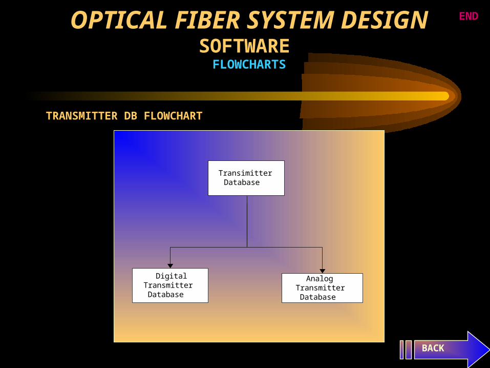
TRANSMITTER DB FLOWCHART
BACK
AnalogTransmitterDatabase
DigitalTransmitterDatabase
TransimitterDatabase
END

OPTICAL FIBER SYSTEM DESIGNSOFTWARE
FLOWCHARTS
FIBER DB FLOWCHART
BACK
DetectorSource
Fiber OpticsSystem
Fiber Link (Cable)
END

OPTICAL FIBER SYSTEM DESIGNSOFTWARE
FLOWCHARTS
RECEIVER FLOWCHART
BACK
DetectorPreAmplifier
Receiverdatabases
Attenuator
ControlledVoltage Vc
VoltageRatio Vo/Vi
END
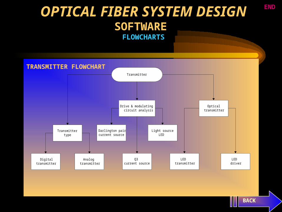
Transmitter
Transmittertype
Drive & modulatingcircuit analysis
Opticaltransmitter
LEDdriver
LEDtransmitter
Light sourceLED
Q3current source
Darlington paircurrent source
Analogtransmitter
Digitaltransmitter
OPTICAL FIBER SYSTEM DESIGNSOFTWARE
FLOWCHARTS
TRANSMITTER FLOWCHART
BACK
END

Start
SystemRequirements
Multiwavelength
SelectMonomode
Cable
SelectMultimode
Cable
CalculateCoupling
Loss
LossAcceptable
Try AnotherCable
CableAccepted
All CablesConsidered
CalculateDispersion
BandwidthAcceptable
Save Datato File
Cable TechnicalChracteristics
and ManufactureCompany and
Adress
End
Reduce SystemRequirements
YesNo
No
Yes
Yes
No
No
Yes
Yes
No
Yes
OP
TIC
AL
FIB
ER
SY
ST
EM
DE
SIG
NS
OF
TW
AR
E
FL
OW
CH
AR
TS
CABLE FLOWCHART
BACK
END

DetectorPreAmplifier
Receiverdatabases
Attenuator
ControlledVoltage Vc
VoltageRatio Vo/Vi
OPTICAL FIBER SYSTEM DESIGNSOFTWARE
FLOWCHARTS
RECEIVER FLOWCHART
BACK
END

OP
TIC
AL
FIB
ER
SY
ST
EM
DE
SIG
NS
OF
TW
AR
E
FL
OW
CH
AR
TS
EC
ON
OM
Y F
LO
WC
HA
RT
SpecifyK, B, Qu
The totalengineering
cost
The unit costof material, Cm
The wast costper manu.unit,
Cw
Cw>Cm
The assemblycost per unit,
Cas
The cost ofsupport & test
eq., Ce
The cost ofquality cont.per unit, Qqc
The CER
The cost ofmanufacturing,
Cma
Another run
Stop
BACK
END

LINK
Select approachA or B
Automaticprocessing of several
combinations
Specify L, B, BER,SF and SM
Select designsequence
Load data file
Single combinationdirect processing
Specify L, B, BER,SF and SM
Select designpriority
Allaccepteddesigns
Bestperformance
(don't considercost)
Less thanspecified
cost
Lowestcost
DetectorFiber
Source
SourceFiber
Detector
SourceDetector
Fiber
FiberSource
Detector
FiberDetectorSource
DetectorSourceFiber
Approache BApproache A
OPTICAL FIBER SYSTEM DESIGNSOFTWARE
FLOWCHARTS
LINK FLOWCHART
BACK
EXAMPLE
END

Lowest cost
Read set ofsource data
Source rise-time O.K
Read set ofdetector data
All fiberstried
Sys. rise-timeO.K
Det.+Sourcerise-time O.K
Allcombination
tried
Save result
Power O.K
Calculate det.sensitivity
CalculateCable Margin
Calculate newfiber rise-time
Calculate fiberloss
Calculatematerial cost
Store designdata
Save Result tofile
Stop
Next Source
Allsources
tried
N=N+1L=L/(N+1)
TryRepeater
Stop
Alldetectors
tried
Nextdetector
Next Fiber
yes
no
no
yes
no
yes
no
yes
yes
no
yes
no
yes
no
no
yes
no
yes
yes no
Less cost than lastcombination
yes
no
LO
WE
ST
CO
ST
FL
OW
CH
AR
T
BACK
HOW THE PROGRAM USES THE DATABASE END O
PT
ICA
L F
IBE
R S
YS
TE
M D
ES
IGN
SO
FT
WA
RE
F
LO
WC
HA
RT
S

OP
TIC
AL
FIB
ER
SY
ST
EM
DE
SIG
NS
OF
TW
AR
E
FL
OW
CH
AR
TS
LE
SS TH
AN
SPE
CIF
IED
CO
ST
FL
OW
CH
AR
T
Less than specified cost
Read set ofsource data
Source rise-time O.K
Read set ofdetector data
All fiberstried
Sys. rise-timeO.K
Det.+Sourcerise-time O.K
Allcombination
tried
Save result
Power O.K
Calculate det.sensitivity
CalculateCable Margin
Calculate newfiber rise-time
Calculate fiberloss
Store designdata
Save Result tofile
Stop
Next Source
Allsources
tried
N=N+1L=L/(N+1)
TryRepeater
Stop
Alldetectors
tried
Nextdetector
Next FiberLess rise-time than
last combination
yes
no
no
yes
no
yes
yes
no
noyes
no
yes
yes
no
noyes
yes
no
yes
CalculateMatrial cost
Less cost thanspecified
no
yes
no
yes
BACK
HOW THE PROGRAM USES THE DATABASE END

OP
TIC
AL
FIB
ER
SY
ST
EM
DE
SIG
NS
OF
TW
AR
E
FL
OW
CH
AR
TS
BE
ST P
ER
FO
MA
NC
E (D
O N
OT
CO
NS ID
ER
CO
ST) F
LO
WC
HA
RT
Best performance (do notconsider cost)
Read set ofsource data
Source rise-time O.K
Read set ofdetector data
All fiberstried
Sys. rise-timeO.K
Det.+Sourcerise-time O.K
Allcombination
tried
Save result
Power O.K
Calculate det.sensitivity
CalculateCable Margin
Calculate newfiber rise-time
Calculate fiberloss
Store designdata Save Result to
file
Stop
Next Source
Allsources
tried
N=N+1L=L/(N+1)
TryRepeater
Stop
Alldetectors
tried
Nextdetector
Next Fiber
Less rise-time thanlast combination
yes
no
no
yes
no
yes
yes
no
noyes
no
yes
yes
no
no
yes
yes
no
no
yesno yes
BACK
HOW THE PROGRAM USES THE DATABASE END
OP
TIC
AL
FIB
ER
SY
ST
EM
DE
SIG
NS
OF
TW
AR
E
FL
OW
CH
AR
TS
AL
L A
CC
EP
TE
D D
ESIG
NS
FL
OW
CH
AR
T
BACK
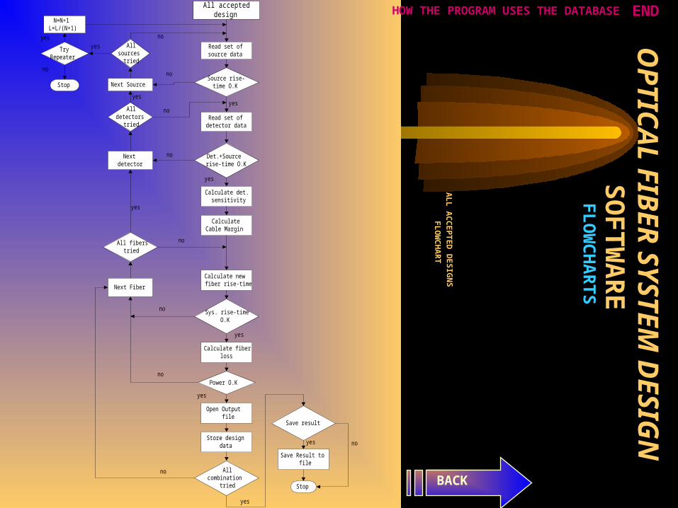
All accepteddesign
Read set ofsource data
Source rise-time O.K
Read set ofdetector data
All fiberstried
Sys. rise-timeO.K
Det.+Sourcerise-time O.K
Allcombination
tried
Save result
Power O.K
Calculate det.sensitivity
CalculateCable Margin
Calculate newfiber rise-time
Calculate fiberloss
Open Outputfile
Store designdata
Save Result tofile
Stop
Next Source
Allsources
tried
N=N+1L=L/(N+1)
TryRepeater
Stop
Alldetectors
tried
Nextdetector
Next Fiber
yes
no
no
yes
no
yes
no
yes
yes
no
yes
no
yes
no
no
yes
no
yes
yes no
HOW THE PROGRAM USES THE DATABASE END

OPTICAL FIBER SYSTEM DESIGNSOFTWARE
FLOWCHARTS
HO
W T
HE
PR
OG
RA
M U
SE
S T
HE
DA
TA
BA
SE
BACK
Source # 1
Source # 2
Source # …
Source # 8
Source # 7
Source # 6
Source # 3
Source # 5
Source # 4
Detector # 1 Fiber # 1
Fiber # 2
Fiber # …..
Fiber # 8
Fiber # 7
Fiber # 6
Fiber # 3
Fiber # 5
Fiber # 4
Detector # 2
Detector # 3
Detector # 4
Detector # 5
Detector # 6
Detector # 7
Detector # 8
Detector # …
Source # X Detector # X Fiber # X ACCEPTED DESIGN
END

OP
TIC
AL
FIB
ER
SY
ST
EM
DE
SIG
NS
OF
TW
AR
E
FL
OW
CH
AR
TS
AL
L A
CC
EP
TE
D D
ESIG
NS
FL
OW
CH
AR
T
BACK
All accepteddesign
Read set ofsource data
Source rise-time O.K
Read set ofdetector data
All fiberstried
Sys. rise-timeO.K
Det.+Sourcerise-time O.K
Allcombination
tried
Save result
Power O.K
Calculate det.sensitivity
CalculateCable Margin
Calculate newfiber rise-time
Calculate fiberloss
Open Outputfile
Store designdata
Save Result tofile
Stop
Next Source
Allsources
tried
N=N+1L=L/(N+1)
TryRepeater
Stop
Alldetectors
tried
Nextdetector
Next Fiber
yes
no
no
yes
no
yes
no
yes
yes
no
yes
no
yes
no
no
yes
no
yes
yes no
END

OP
TIC
AL
FIB
ER
SY
ST
EM
DE
SIG
NS
OF
TW
AR
E
FL
OW
CH
AR
TS
SOU
RC
E/F
IBE
R/D
ET
EC
TO
R
FL
OW
CH
AR
T
BACK
SourceDetector
Fiber
Selectsource type
LEASER LED
Input sourcedata
Select fibertype
Singlemode
Gradedindex
Step index
Input fiberdata
Selectdetector
type
APD PIN
Input detectordata
Source
N=N+!L=L/(N+1)
Input fiberdata
Input sourcedata
Fiber
Detector
Save to file
Show outputresult
Calculate sys.power
Calculate sys.rise-time
Design isO.K
Save resultto file?
Tryrepeater
Upgrade sys.components
Select componentto be upgraded
Stop
Input detectordata
no
yes
no yes no
yes
no yes
END

OP
TIC
AL
FIB
ER
SY
ST
EM
DE
SIG
NS
OF
TW
AR
E
FL
OW
CH
AR
TS
SOU
RC
E/D
ET
EC
TO
R /F
IBE
R
FL
OW
CH
AR
T
BACK
SourceDetector
Fiber
Selectsource type
LEASER LED
Input sourcedata
Select fibertype
Singlemode
Gradedindex
Step index
Input fiberdata
Selectdetector
type
APD PIN
Input detectordata
Source
N=N+!L=L/(N+1)
Input fiberdata
Input sourcedata
Fiber
Detector
Save to file
Show outputresult
Calculate sys.power
Calculate sys.rise-time
Design isO.K
Save resultto file?
Tryrepeater
Upgrade sys.components
Select componentto be upgraded
Stop
Input detectordata
no
yes
no yes no
yes
no yes
END

OP
TIC
AL
FIB
ER
SY
ST
EM
DE
SIG
NS
OF
TW
AR
E
FL
OW
CH
AR
TS
FIB
ER
/SOU
RC
E /D
ET
EC
TO
R
FL
OW
CH
AR
T
BACK
FiberSource
Detector
Selectsource type
LEASER LED
Input sourcedata
Select fibertype
Singlemode
Gradedindex
Step index
Input fiberdata
Selectdetector
type
APD PIN
Input detectordata
Source
N=N+!L=L/(N+1)
Input fiberdata
Input sourcedata
Fiber
Detector
Save to file
Show outputresult
Calculate sys.power
Calculate sys.rise-time
Design isO.K
Save resultto file?
Tryrepeater
Upgrade sys.components
Select componentto be upgraded
Stop
Input detectordata
no
yes
no yes no
yes
no yes
END

OP
TIC
AL
FIB
ER
SY
ST
EM
DE
SIG
NS
OF
TW
AR
E
FL
OW
CH
AR
TS
FIB
ER
/DE
TE
CT
OR
/ SOU
RC
E
FL
OW
CH
AR
T
BACK
FiberDetectorSource
Selectsource type
LEASER LED
Input sourcedata
Select fibertype
Singlemode
Gradedindex
Step index
Input fiberdata
Selectdetector
type
APD PIN
Input detectordata
Source
N=N+!L=L/(N+1)
Input fiberdata
Input sourcedata
Fiber
Detector
Save to file
Show outputresult
Calculate sys.power
Calculate sys.rise-time
Design isO.K
Save resultto file?
Tryrepeater
Upgrade sys.components
Select componentto be upgraded
Stop
Input detectordata
no
yes
no yes no
yes
no yes
END

OP
TIC
AL
FIB
ER
SY
ST
EM
DE
SIG
NS
OF
TW
AR
E
FL
OW
CH
AR
TS
DE
TE
CT
OR
/SOU
RC
E/F
IBE
R
FL
OW
CH
AR
T
BACK
DetectorSourceFiber
Selectsource type
LEASER LED
Input sourcedata
Select fibertype
Singlemode
Gradedindex
Step index
Input fiberdata
Selectdetector
type
APD PIN
Input detectordata
Source
N=N+!L=L/(N+1)
Input fiberdata
Input sourcedata
Fiber
Detector
Save to file
Show outputresult
Calculate sys.power
Calculate sys.rise-time
Design isO.K
Save resultto file?
Tryrepeater
Upgrade sys.components
Select componentto be upgraded
Stop
Input detectordata
no
yes
no yes no
yes
no yes
END

OP
TIC
AL
FIB
ER
SY
ST
EM
DE
SIG
NS
OF
TW
AR
E
FL
OW
CH
AR
TS
DE
TE
CT
OR
/FIB
ER
/ SOU
RC
E
FL
OW
CH
AR
T
BACK
DetectorFiber
Source
Selectsource type
LEASER LED
Input sourcedata
Select fibertype
Singlemode
Gradedindex
Step index
Input fiberdata
Selectdetector
type
APD PIN
Input detectordata
Source
N=N+!L=L/(N+1)
Input fiberdata
Input sourcedata
Fiber
Detector
Save to file
Show outputresult
Calculate sys.power
Calculate sys.rise-time
Design isO.K
Save resultto file?
Tryrepeater
Upgrade sys.components
Select componentto be upgraded
Stop
Input detectordata
no
yes
no yes no
yes
no yes
END

OPTICAL FIBER SYSTEM DESIGNSOFTWARE DESIGN EXAMPLE
DESIGN SPECIFICATION:LINK LENGTH = 20 KM
DATA RATE = 140 Mbit/s
BIT ERROR RATE = 1E-10
SIGNAL FORMAT = NRZ
SYSTEM MARGIN = 6 dB
BACK
BANDWIDTH BUDGET : (computed)
Maximum allowed risetime = 5 ns
POWER BUDGET: (computed)
The excess power margin >= 0 dB
• SOURCE DATA • MANUALDESIGN RESULT
• FIBER DATA
• DETECTOR DATA • SOFTWARE DESIGN RESULT
END
OPTICAL FIBER SYSTEM DESIGNSOFTWARE DESIGN EXAMPLE
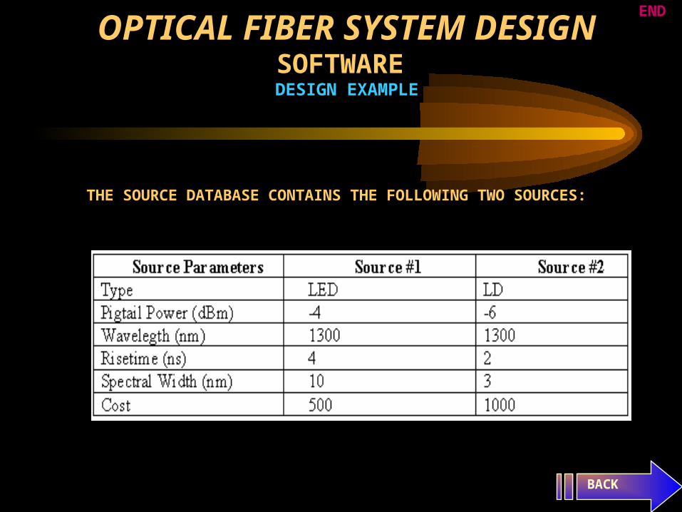
THE SOURCE DATABASE CONTAINS THE FOLLOWING TWO SOURCES:
BACK
END

OPTICAL FIBER SYSTEM DESIGNSOFTWARE DESIGN EXAMPLE
THE FIBER DATABASE CONTAINS THE FOLLOWING TWO FIBERS :
BACK
END
OPTICAL FIBER SYSTEM DESIGNSOFTWARE DESIGN EXAMPLE
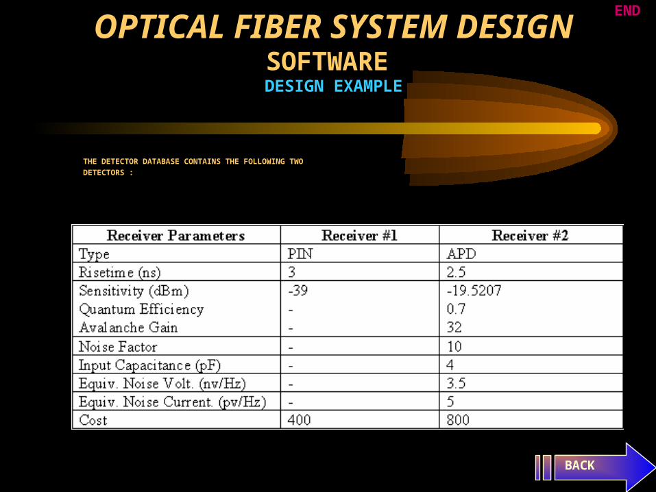
THE DETECTOR DATABASE CONTAINS THE FOLLOWING TWO
DETECTORS :
BACK
END

OPTICAL FIBER SYSTEM DESIGNSOFTWARE DESIGN EXAMPLE
MANUAL DESIGN RESULT
All possible combination are listed below:
BACK
END


