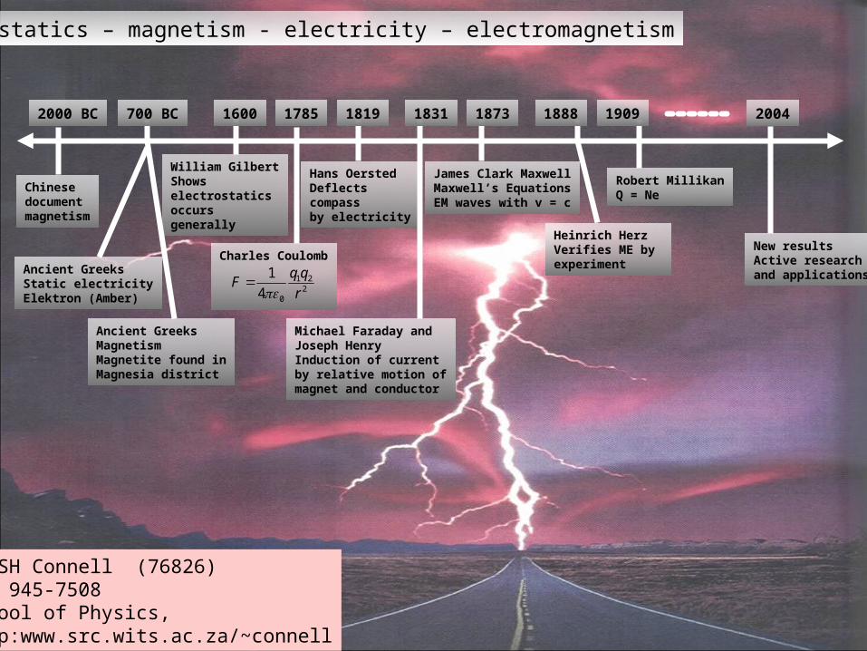
Electrostatics – magnetism - electricity – electromagnetism
Chinese documentmagnetism
Ancient GreeksStatic electricityElektron (Amber)
Ancient GreeksMagnetismMagnetite found inMagnesia district
William GilbertShows electrostaticsoccurs generally
Michael Faraday andJoseph HenryInduction of currentby relative motion ofmagnet and conductor
Heinrich HerzVerifies ME by experiment
James Clark MaxwellMaxwell’s EquationsEM waves with v = c
Charles Coulomb
221
04
1
r
qqF
2000 BC 700 BC
Hans Oersted Deflects compassby electricity
Robert MillikanQ = Ne
1600 1831 18731785 1888 1909 20041819
New resultsActive researchand applications
Dr SH Connell (76826)082 945-7508School of Physics, http:www.src.wits.ac.za/~connell
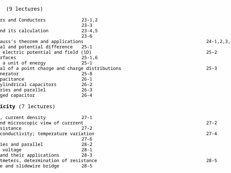
Electrostatics (9 lectures)
Charges Insulators and Conductors 23-1,2Coulomb’s Law 23-3Electric Field and its calculation 23-4,5Lines of force 23-6Electric flux, Gauss’s theorem and applications 24-1,2,3,4Electric Potential and potential difference 25-1Relation between electric potential and field (1D) 25-2Equipotential surfaces 25-1,6Electron volt as a unit of energy 25-1Electric potential of a point charge and charge distributions 25-3Van de Graaff generator 25-8Definition of capacitance 26-1Parallel plate cylindrical capacitors 26-2Capacitors in series and parallel 26-3Energy of a charged capacitor 26-4
Current Electricity (7 lectures)
Electric current, current density 27-1Drift velocity and microscopic view of currrent 27-2Ohm’s Law and resistance 27-2Resistivity and conductivity; temperature variation 27-4Electric Power 27-6Resistors in series and parallel 28-2Emf and terminal voltage 28-1Kirchoff’s laws and their applications 28-3Ammeters and voltmeters, determination of resistance 28-5Wheatstone bridge and slidewire bridge 28-5
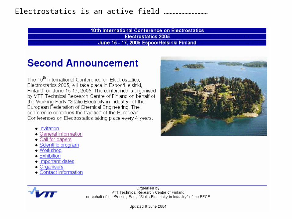
Electrostatics is an active field …………………………


STATIC ELECTRICITY
CURRENTELECTRICITY
ELECTRO-MAGNETISM
“Stationary” chargesInsulators
Moving chargesConductors
(semiconductors)
Due to currents(magneticmaterials)
Forces fieldsPotential Energy
Capacitance
Batteries & circuitsEnergy conversion
Resistance
Forces fieldsGenerate currents
Inductance

+ve nucleusN protons
Charge = +Zenuclear diameter
10-15 m(Rutherford’s exp)Electron charge -e
N electrons
Charge = -Ze
Atomic diam
eter 10 -10m
(Einstein’s analysis of
Brownian Motion)
Shell model of the Atom• small +vely charged nucleus• surrounded by e- in planetary orbits• normal atom is neutral
The atom is mostlyempty space
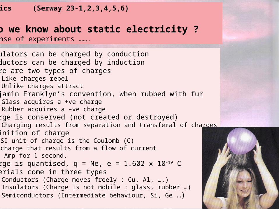
1. Insulators can be charged by conduction2. Conductors can be charged by induction3. There are two types of charges
a) Like charges repelb) Unlike charges attract
4. Benjamin Franklyn’s convention, when rubbed with fura) Glass acquires a +ve chargeb) Rubber acquires a –ve charge
5. Charge is conserved (not created or destroyed)a) Charging results from separation and transferal of charges
6. Definition of chargeMKS/SI unit of charge is the Coulomb (C)The charge that results from a flow of currentof 1 Amp for 1 second.
7. Charge is quantised, q = Ne, e = 1.602 x 10⁻¹⁹ C8. Materials come in three types
a) Conductors (Charge moves freely : Cu, Al, ….)b) Insulators (Charge is not mobile : glass, rubber …)c) Semiconductors (Intermediate behaviour, Si, Ge …)
The Basics (Serway 23-1,2,3,4,5,6)
How do we know about static electricity ?Make sense of experiments …….
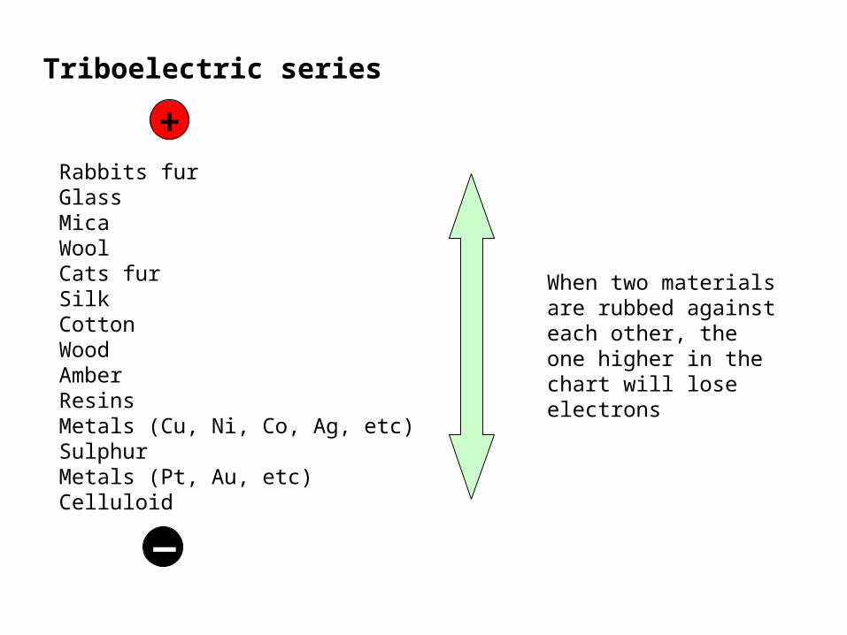
Triboelectric series
Rabbits furGlassMicaWoolCats furSilkCottonWoodAmberResinsMetals (Cu, Ni, Co, Ag, etc)SulphurMetals (Pt, Au, etc)Celluloid
+
_
When two materials are rubbed against each other, the one higher in the chart will lose electrons
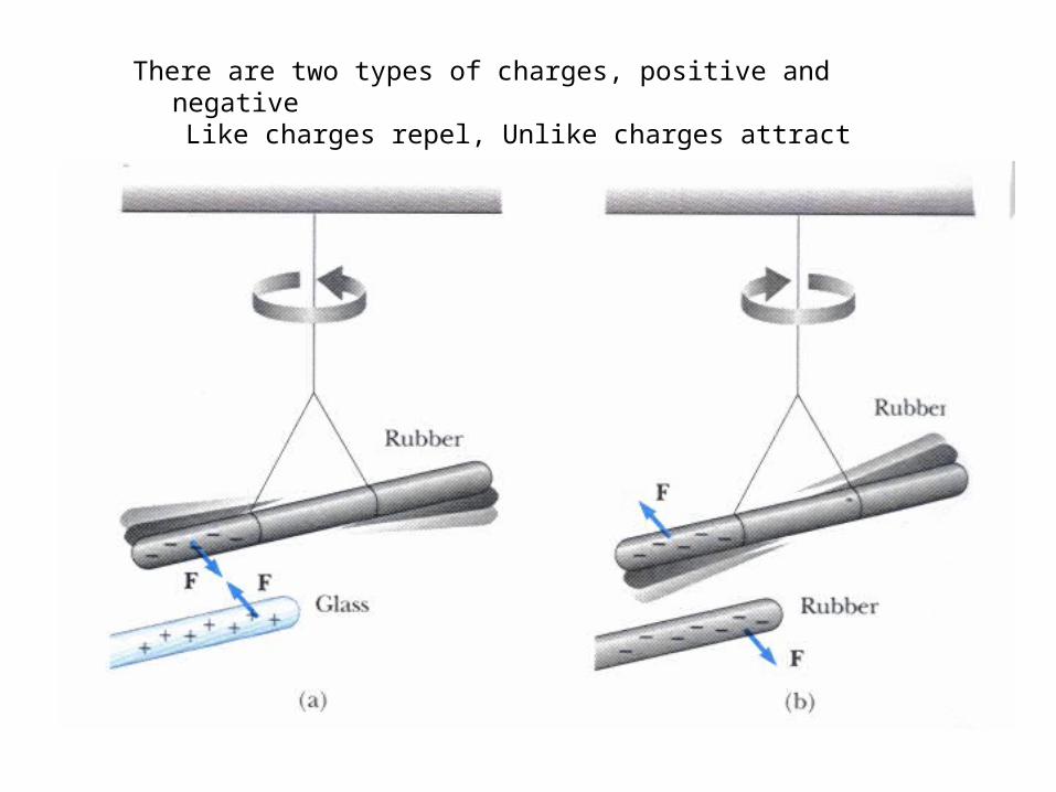
There are two types of charges, positive and negativeLike charges repel, Unlike charges attract
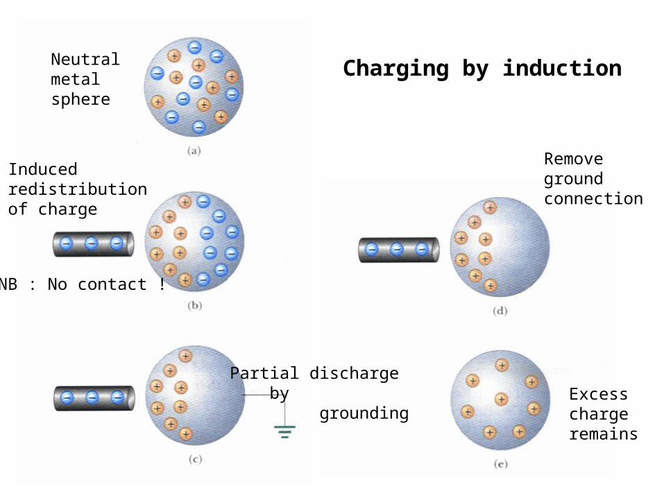
Charging by inductionNeutral metal sphere
Inducedredistributionof charge
NB : No contact !
Removeground connection
Excess chargeremains
Partial discharge by grounding

A charged object induces near-surface charge in an insulatorAtoms or Molecules near the surface are induced to become partial temporary dipolesThis is the mechanism by which the comb attracts the paper

Coulomb’s Torsion Balance
Twist measures repulsive force
Coulomb’s Law
Coulomb showed experimentally that the electric forcebetween two stationary charged particles is1. Inversely proportional to the square of the separation of the
charged particles and directed along the line joining them2. Directly proportional to the product of the two charges.3. Attractive for unlike charges and repulsive for like charges.
221
r
qqkF
If F is in Newtons, q1 and q2 in Coulombs and r in meters, then,
221
04
1
r
qqF
= permittivity of free space = 8.86 x 10⁻¹² C2N-1m-2 or Farads.m-1
thenk = 1/40 = 9 x 10⁹ mF-1

The resultant force in a system of many charges
Force is a vector quantity.The force between two charges is
rF ˆ.4
12
21
012 r
+q1 -q2
and attractive (repulsive) for an overall-ve (+ve) sign.
q1q2 < 0 attractive force
....)0(.....321 nnnnnnR FFFFF
The Principle of Superposition
If there are more than two point charges, then Coulomb’s Law holds for every pair of charges. Let the charges be q1, q2, q3, q4, … qn, ….Then the resultant force on qn is given by the vector sum
See Examples …….
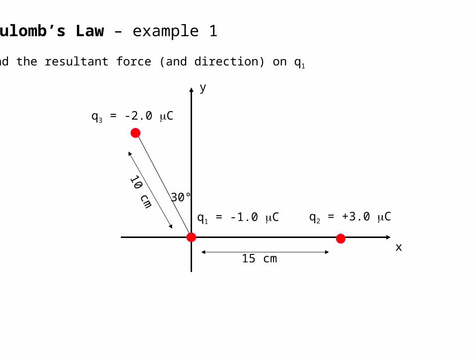
Coulomb’s Law – example 1
Find the resultant force (and direction) on q1
q3 = -2.0 C
q1 = -1.0 C q2 = +3.0 C
15 cm
10 cm
y
x
30°

N102.8
m103.5
C1060.1
C
N.m1099.8
)(.
4
1
8
211
219
2
29
20
r
eZeFe
The Hydrogen Atom
Compare the electrostatic and gravitational the forces(The average separation of the electron and proton r = 5.3 x 10⁻¹¹ m ≈ ½ Å)
+Ze
e
F
vr
N106.3
m103.5
k1067.1k1011.9
k
N.m107.6
47
211
2731
2
211
2g
gg
gr
mmGF pe
Fe/Fg = 2 x 1039 The force of gravity is much weaker than the electrostatic force
What other fundamental differences are there ?

Coulomb’s Law – example 2
A certain charge Q is to be divided into two parts, q and Q-q.
What is the relationship of q to Q if the two charges, placed a given distance apart, are to have a maximum coulomb repulsion ?
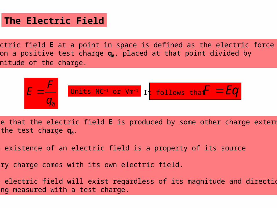
The Electric Field
The electric field E at a point in space is defined as the electric force F,acting on a positive test charge q0, placed at that point divided by the magnitude of the charge.
0q
FE
Note that the electric field E is produced by some other charge external to the test charge q0.
The existence of an electric field is a property of its source
Every charge comes with its own electric field.
The electric field will exist regardless of its magnitude and directionbeing measured with a test charge.
Units NC-1 or Vm-1 It follows that EqF

Electric field lines These are a way of visualizing the electric field. The electric field vector E is tangential to the electric field line at any point. The magnitude of the electric field vector E is proportional to the density of the lines. Electric field lines can never cross.
For a positive point charge, the lines are directed radialy outward.
For a negative point charge, the lines are directed radialy inward.
An electric dipole has two nearby point charges of equal magnitude q and opposite sign, separated by a distance d. The number of lines leaving the positive charge equals the number of lines entering the negative charge.
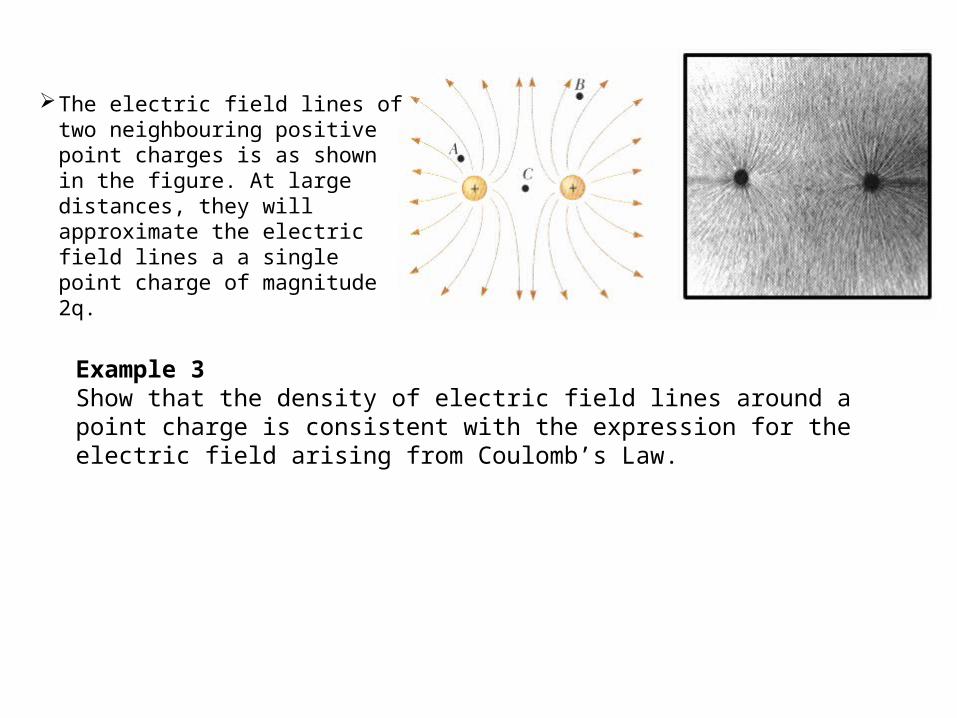
The electric field lines of two neighbouring positive point charges is as shown in the figure. At large distances, they will approximate the electric field lines a a single point charge of magnitude 2q.
Example 3Show that the density of electric field lines around a point charge is consistent with the expression for the electric field arising from Coulomb’s Law.
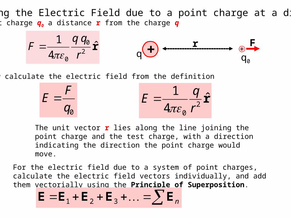
Calculating the Electric Field due to a point charge at a distance rPlace a point charge q0 a distance r from the charge q
r̂4
12
0
0 r
qqF
Now calculate the electric field from the definition
0q
FE r̂
4
12
0 r
qE
The unit vector r lies along the line joining the point charge and the test charge, with a direction indicating the direction the point charge would move.
For the electric field due to a system of point charges, calculate the electric field vectors individually, and add them vectorially using the Principle of Superposition.
++q q0
r F
nEEEEE 321
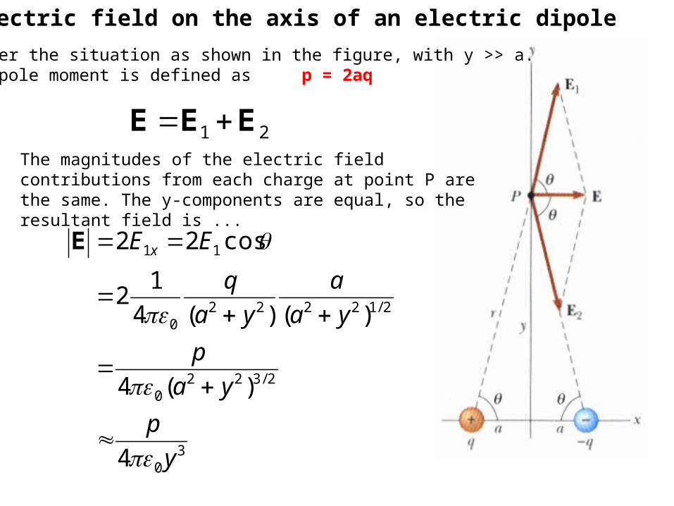
The electric field on the axis of an electric dipole
21 EEE
Consider the situation as shown in the figure, with y >> a.The dipole moment is defined as p = 2aq
The magnitudes of the electric field contributions from each charge at point P are the same. The y-components are equal, so the resultant field is ...
30
2/3220
2/122220
11
4
)(4
)()(4
12
cos22
y
p
ya
p
ya
a
ya
q
EE x
E
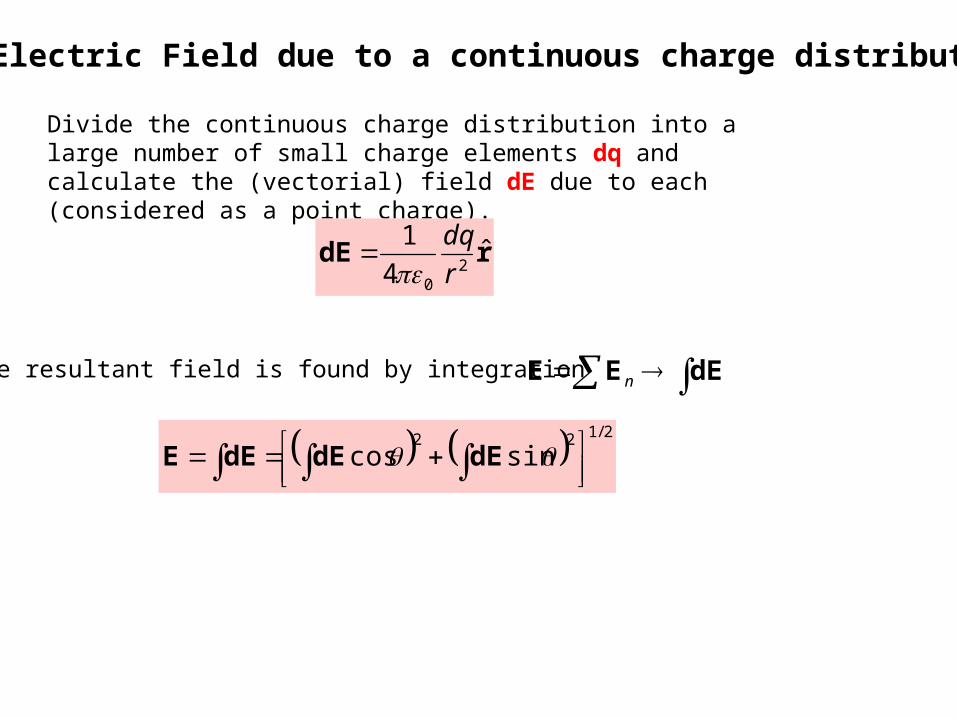
The Electric Field due to a continuous charge distribution
Divide the continuous charge distribution into a large number of small charge elements dq and calculate the (vectorial) field dE due to each (considered as a point charge).
rdE ˆ4
12
0 r
dq
The resultant field is found by integration
2/122sincos
dEdEdEE
dEEE n
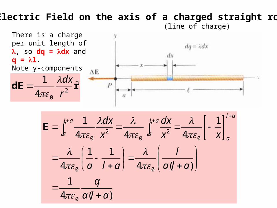
The Electric Field on the axis of a charged straight rod(line of charge)
There is a charge per unit length of , so dq = dx and q = l.Note y-components cancel
rdE ˆ4
12
0 r
dx
)(4
1
)(4
11
4
1
444
1
0
00
02
02
0
ala
q
ala
l
ala
xx
dx
x
dxal
a
al
a
al
a
E
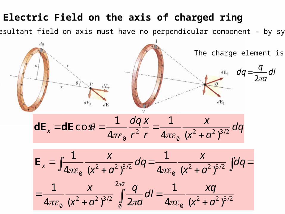
The Electric Field on the axis of charged ring
The resultant field on axis must have no perpendicular component – by symmetry.
dqax
x
r
x
r
dqx 2/322
02
0 )(4
1
4
1cos
dEdE
2/3220
2
02/322
0
2/3220
2/3220
)(4
1
2)(4
1
)(4
1
)(4
1
ax
xqdl
a
q
ax
x
dqax
xdq
ax
x
a
x
E
The charge element is
dla
qdq
2

The cathode ray tube
This device is used to display electronic information from oscilloscopes, radar systems, television receivers and computer monitors.
An electron beam is produced by an electron gun, which consists of a biased hot filament together with intensity control, acceleration and focusing electrodes.
The monoenergetic electron beam (usually a few keV of energy) will strike the screen producing a luminous point at a location determined by the electric field of parallel deflection plates, arranged to control both the x and the y deflection of the beam.
The signals on the electrodes of the x and y deflection plates, as well as the intensity control electrode, determine the image that is visualised.

The flux of E (Serway 24.1-24.4)
We can imagine drawing electric field lines so that the number of lines per unit area perpendicular to the field is proportional to the field strength.
Flux density : The number of field lines per unit area, perpendicular to the field direction (a vector quantity). This quantity is proportional to Electric field strength E.
Flux (symbol E) : is the total number of field lines passing through a particular area (a scalar quantity).
It follows …. cosEAEAE E.A

Area elementsWe assumed a uniform E field and a flat area in the previous discussion.
If we take an infinitesimally small area element, then locally, the field will be uniform and the area element flat. The flux through this area element (number of field lines through this area element) is ….
dA
E cos. EdAdAd E E
An area element is therefore a vector with an orientation of its surface normal and a magnitude of its area. (Actually, the orientation could also be the opposite direction. This is explained later.)
Total flux through a finite surfaceIntegrate the infinitesimal contributions …(example of a surface integral of a vector field)
A
E dA.E
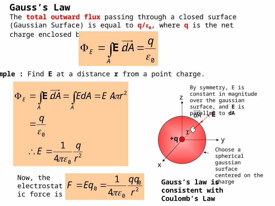
Gauss’s LawThe total outward flux passing through a closed surface (Gaussian Surface) is equal to q/0, where q is the net charge enclosed by the surface.
0
.q
dAA
E EExample : Find E at a distance r from a point charge.
x
z
y
dA E
+qr
Choose a spherical gaussian surface centered on the charge
20
0
2
4
1
4..
r
qE
q
rEEdAdAAA
E
E
Now, the electrostatic force is
Gauss’s law is consistent with Coulomb’s Law2
0
00 4
1
r
qqEqF
By symmetry, E is constant in magnitude over the gaussian surface, and E is parallel to dA

Note : The orientation of the vectorial area element is always outwards by convention for a closed surfaceNote : The presence of outside charges has no effect on the total flux passing though the gaussian surface. Inward flux is (-ve), outward flux is (+ve).
dA
+qGaussian surface
Note : Under conditions of symmetry, Gauss’s Theorem is extremely powerful, allowing conclusions to be drawn and solutions to be calculated very efficiently.
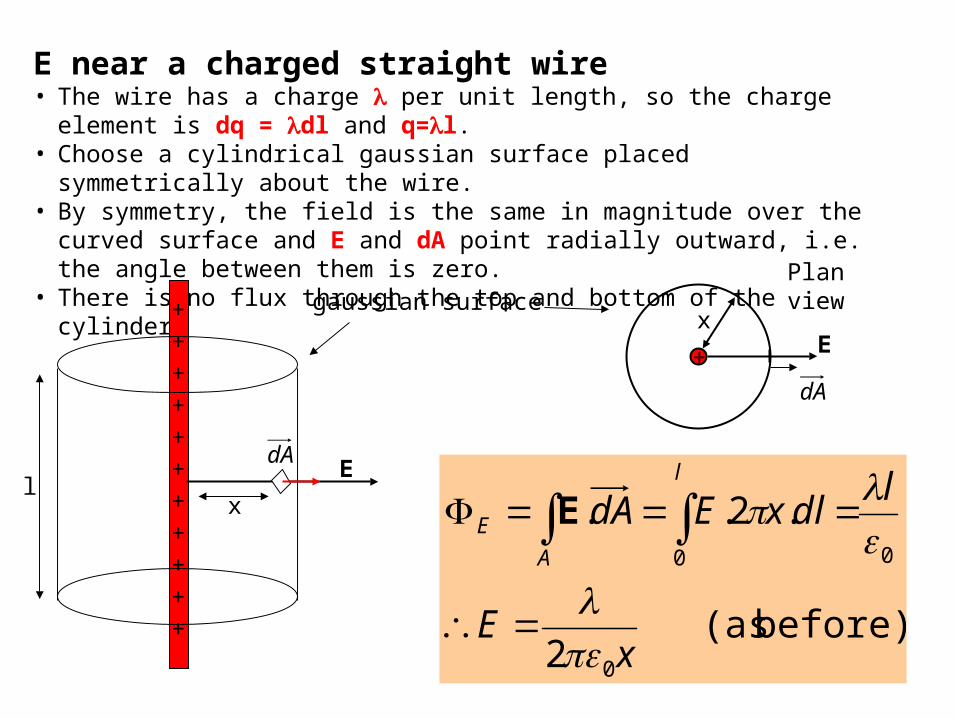
E near a charged straight wire• The wire has a charge per unit length, so the charge element is dq = dl
and q=l. • Choose a cylindrical gaussian surface placed symmetrically about the wire. • By symmetry, the field is the same in magnitude over the curved surface and
E and dA point radially outward, i.e. the angle between them is zero. • There is no flux through the top and bottom of the cylinder.
before) (as 2
.2..
0
00
xE
ldlxEdA
l
A
E
E
+ E
dA
xgaussian surface
++
++
++
++
++
+
EdA
xl
Plan view

E near a charged isolated conductor, any shape.• There is no further motion of charge within the conductor once equilibration
has been attained, in an isolated conductor.• Hence there is no field inside the conductor (otherwise free electrons would
move, F = qE).• Also, E must be perpendicular to the surface, as there can be no component
of E lying in the surface.charged isolated conductor
gaussian surface
• Choose a gaussian surface just under the charged conductor surface as shown.• Since E is zero inside, E=0 for this gaussian surface. Hence by Gauss’s
Theorem, there is no charge within the gaussian surface.• If an isolated conductor is charged, then all the charge is on the outside of
the conductor
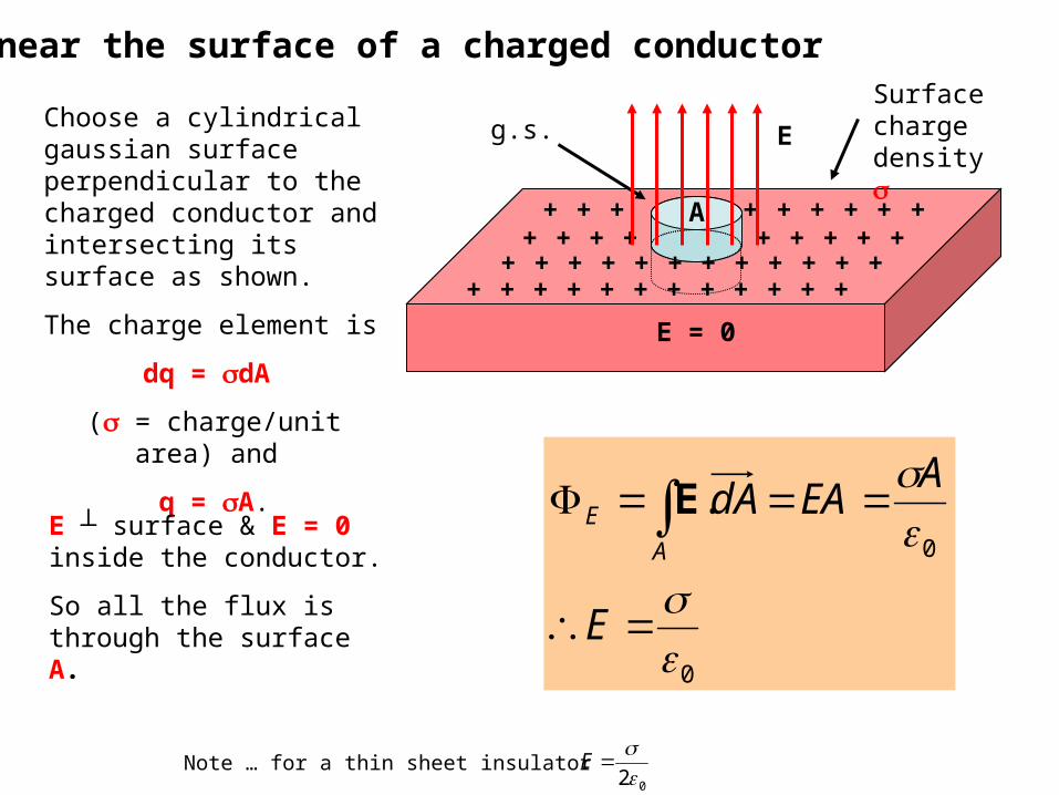
E near the surface of a charged conductor
+ + + + + + + + ++ + + + + + + + +
+ + + + + + + + + + + ++ + + + + + + + + + + +
Eg.s.
A
E = 0
Choose a cylindrical gaussian surface perpendicular to the charged conductor and intersecting its surface as shown.
The charge element is
dq = dA
( = charge/unit area) and
q = A.
E ┴ surface & E = 0 inside the conductor.
So all the flux is through the surface A.
.
0
0
E
AEAdA
A
E E
Note … for a thin sheet insulator 2 0
E
Surface charge density
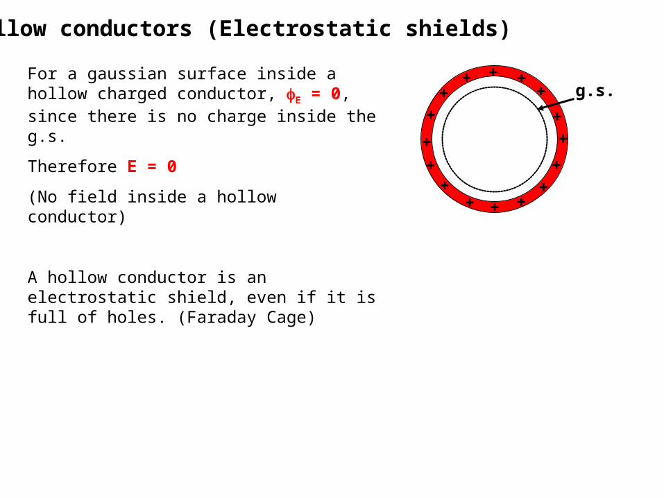
Hollow conductors (Electrostatic shields)
For a gaussian surface inside a hollow charged conductor, E = 0, since there is no charge inside the g.s.
Therefore E = 0
(No field inside a hollow conductor)
A hollow conductor is an electrostatic shield, even if it is full of holes. (Faraday Cage)
+
+
++
++
+ ++
+
++
+
+
+ +
g.s.

Electric Potential and potential difference (Serway 25-1,2,3,6,8)If the work done by an external agent in moving a charge +q0 from point A to point B is WAB, then the potential difference between points A and B (the potential at point B w.r.t. the point A) is defined as
ABBA
AB Vq
WVVV
0BA -
Note If WAB is +ve, then B is at a higher potential than A. Units are work/charge = joule/coulomb ≡ volt (V). Potential difference is a scalar quantity Potential energy refers to a charge-field system (work done to
introduce a charge to a field). Electric potential is a scalar characteristic of an electric field, independent of any other charges.
WAB depends only the endpoints, not the path. Therefore the E-field is a conservative field.
If we take point A to be at infinity, then it will feel no E-field and we set the potential here to be zero.
Ending at point A, starting at point B
0B
q
WV B
Work done in bringing q0 in from infinity to B.So VB is the work done per unit charge to bring a positive test charge to point B
Ending at point B, starting at point A

Electric potential and electric fieldThe work done by an external agent in moving a charge +q0 from point A to point B is WAB,. (This would be the negative of the work done by the field on the charge.)
dlqdlWB
A
B
A
BA .. 0 EF
Therefore,
dldlqq
WVVV
B
A
B
A
BAABBA ..
1
00
EF
Similarly,
dlVVVB
BB
.E
Q
J11Volt potential Electric : Units
From the above definitions we see,
m
V1
Q
N1field-E
EldlVB
A
BA )/(. E
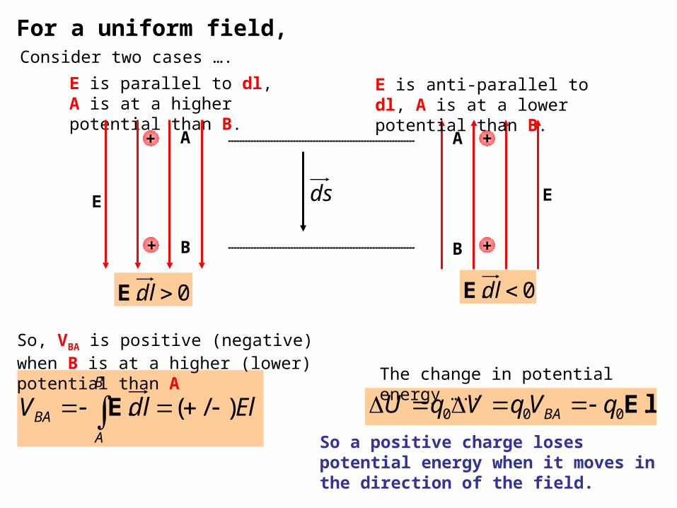
For a uniform field,
E is parallel to dl, A is at a higher potential than B.
AA
BB
+
+
+
+
E Eds
0. dlE0. dlE
E is anti-parallel to dl, A is at a lower potential than B.
Consider two cases ….
So, VBA is positive (negative) when B is at a higher (lower) potential than A
So a positive charge loses potential energy when it moves in the direction of the field.
lE.000 qVqVqU BA The change in potential energy …..

Equipotential surfaces
A B
C
s
EIn the figure, points B and C are at the same potential.
Points B and C therefore lie on an equipotential surface
Equipotential Surface : Any surface consisting of a continuous distribution of points having the same electric potential.
An equipotential surface is perpendicular to the lines of electric field.
Energy unit the electron voltThe electron volt (eV) : The energy an electron (or proton) gains or loses by
moving through a potential difference of 1 volt.
J1061VC1061eV1 1919 -- ..
Example : An electron in a TV tube has a velocity v = 3.5x10⁷ m/s which is a kinetic energy of Ek = ½mv2 = 5.6x10⁻¹⁶ J which is equivalent to 3.5x10³ eV. This corresponds to the electron being accelerated from rest through a potential difference of 3.5 kV.
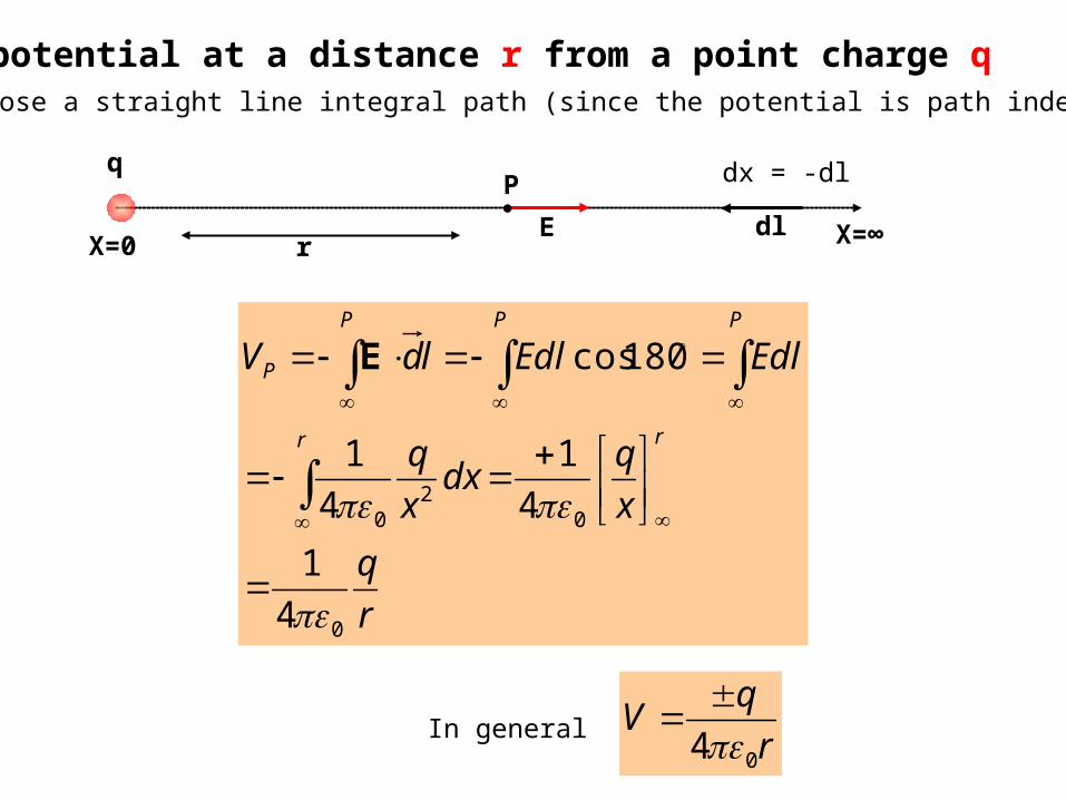
The potential at a distance r from a point charge qWe can choose a straight line integral path (since the potential is path independent)
P
r X=∞
q
X=0E dl
r
q
x
qdx
x
q
EdlEdlldV
rr
PPP
P
0
02
0
4
1
4
1
4
1
180cos
E
In generalr
qV
04
dx = -dl
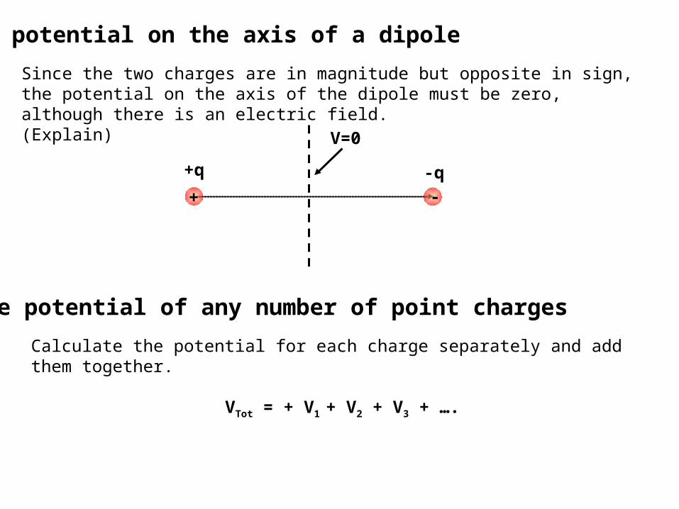
The potential on the axis of a dipole
Since the two charges are in magnitude but opposite in sign, the potential on the axis of the dipole must be zero, although there is an electric field.(Explain)
+q -q
+
V=0
The potential of any number of point charges
Calculate the potential for each charge separately and add them together.
VTot = + V1 + V2 + V3 + ….
-
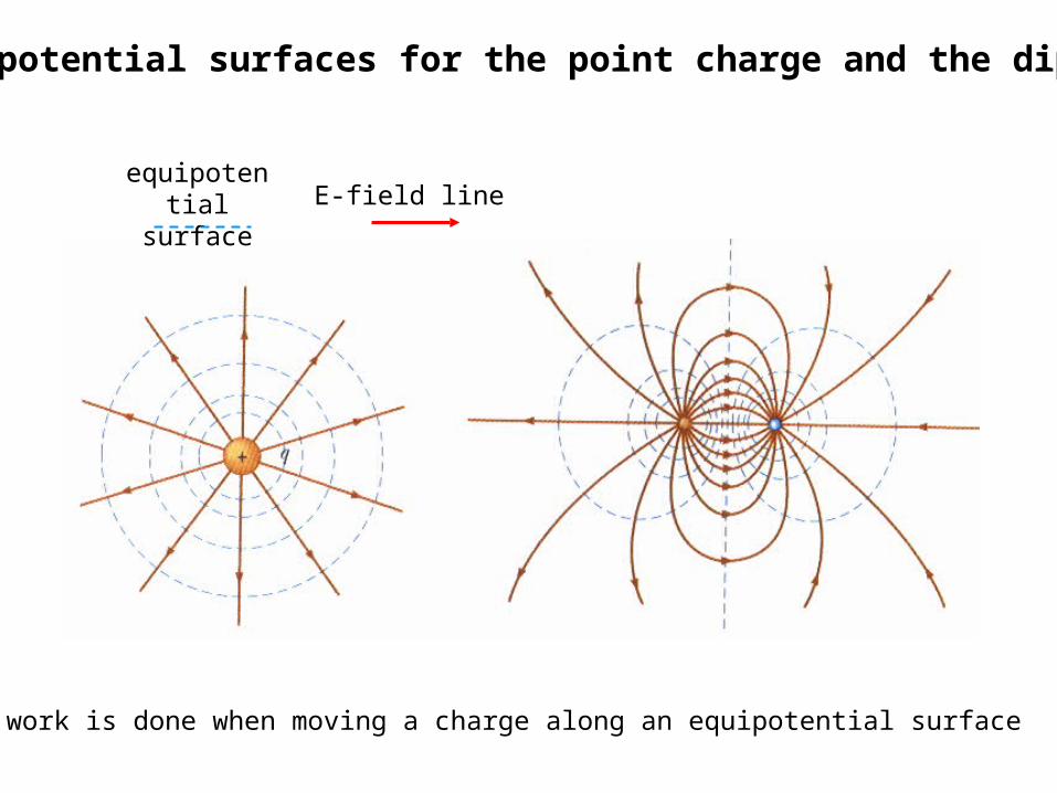
Equipotential surfaces for the point charge and the dipole
No work is done when moving a charge along an equipotential surface
equipotential surface E-field line
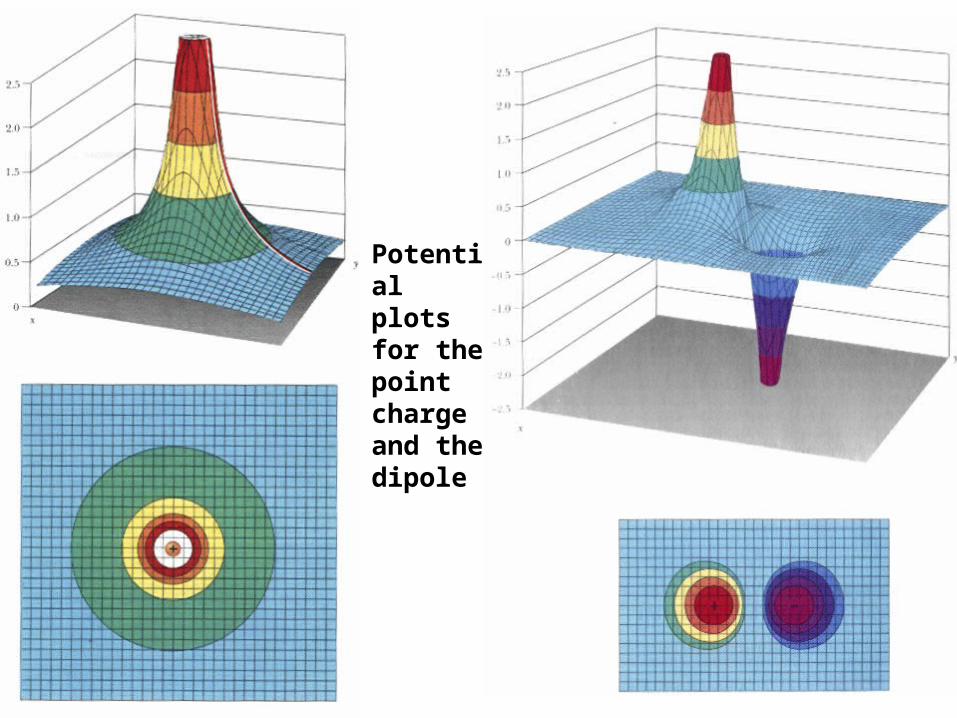
Potential plots for the point charge and the dipole
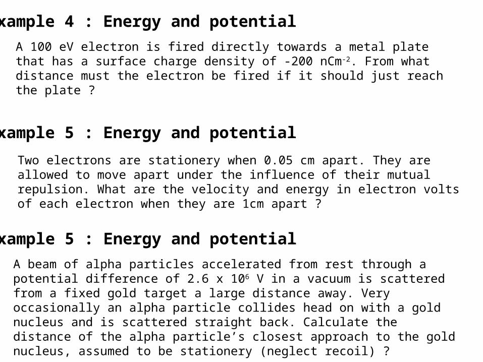
Example 4 : Energy and potential
A 100 eV electron is fired directly towards a metal plate that has a surface charge density of -200 nCm-2. From what distance must the electron be fired if it should just reach the plate ?
Example 5 : Energy and potential
Two electrons are stationery when 0.05 cm apart. They are allowed to move apart under the influence of their mutual repulsion. What are the velocity and energy in electron volts of each electron when they are 1cm apart ?
Example 5 : Energy and potential
A beam of alpha particles accelerated from rest through a potential difference of 2.6 x 10⁶ V in a vacuum is scattered from a fixed gold target a large distance away. Very occasionally an alpha particle collides head on with a gold nucleus and is scattered straight back. Calculate the distance of the alpha particle’s closest approach to the gold nucleus, assumed to be stationery (neglect recoil) ?

Applications of Electrostatics
Van de Graaff Generator Electrical breakdown of the air due to corona discharge occurs at a field Emax
max
maxmin
min0max
2min0
max
4
4
E
VR
R
QV
R
QE
Emax = 3 x 10⁶ Vm-1, so if we want Vmax = 1 x 10⁶ V, then
m33.0103
1016
6
min
R
Note : E (and ) are more concentrated where r is small – especially at sharp points Applications ….

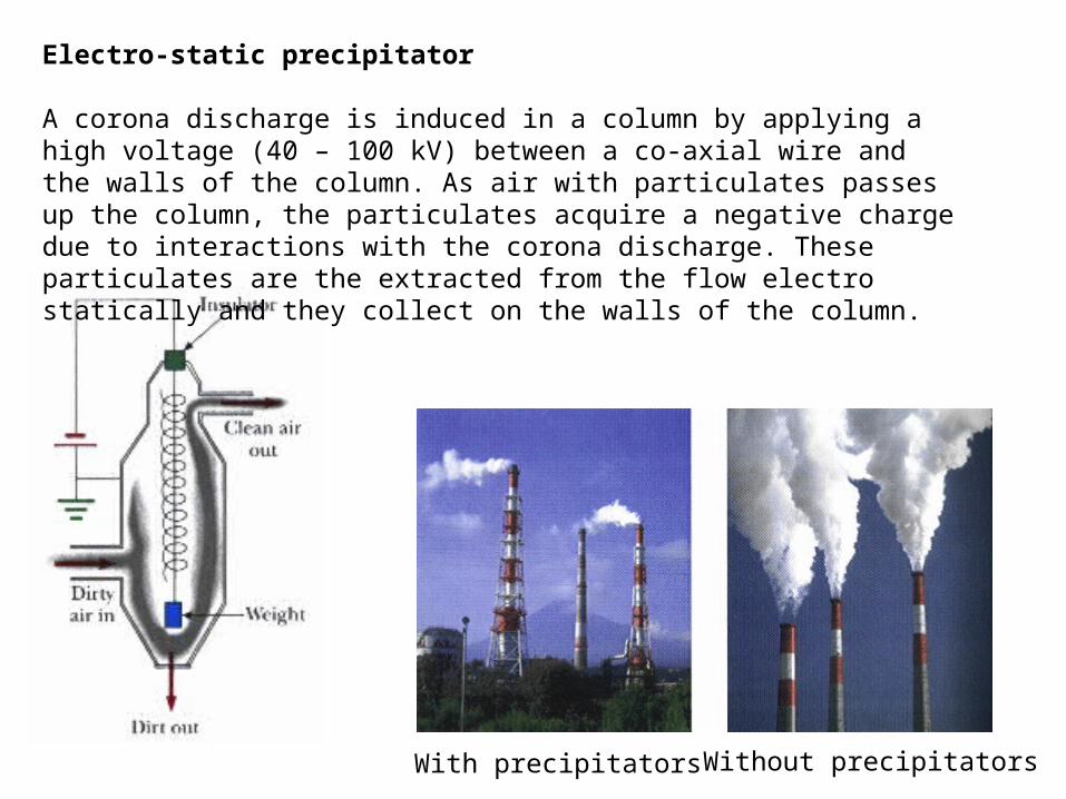
Electro-static precipitator
A corona discharge is induced in a column by applying a high voltage (40 – 100 kV) between a co-axial wire and the walls of the column. As air with particulates passes up the column, the particulates acquire a negative charge due to interactions with the corona discharge. These particulates are the extracted from the flow electro statically and they collect on the walls of the column.
With precipitators Without precipitators
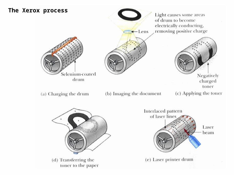
The Xerox process
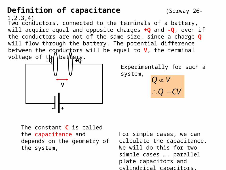
Definition of capacitance (Serway 26-1,2,3,4)
Two conductors, connected to the terminals of a battery, will acquire equal and opposite charges +Q and -Q, even if the conductors are not of the same size, since a charge Q will flow through the battery. The potential difference between the conductors will be equal to V, the terminal voltage of the battery.
V
+-
+Q-QExperimentally for such a system,
CVQ
VQ
The constant C is called the capacitance and depends on the geometry of the system,
For simple cases, we can calculate the capacitance.We will do this for two simple cases …. parallel plate capacitors and cylindrical capacitors,
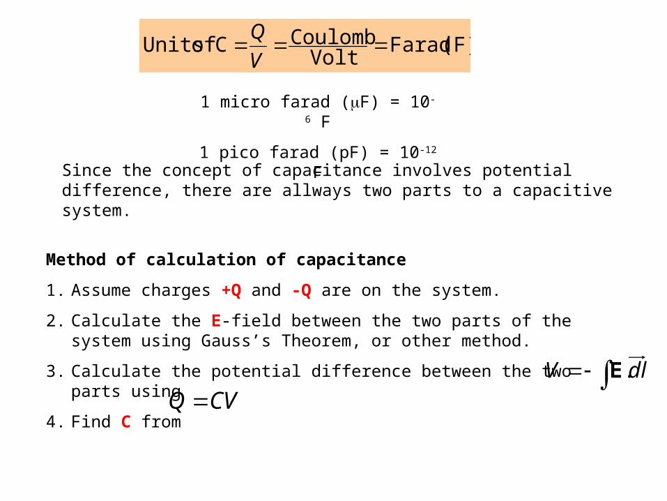
(F) FaradVolt
Coulomb C of Units V
Q
1 micro farad (F) = 10-6 F
1 pico farad (pF) = 10-12 F
Since the concept of capacitance involves potential difference, there are allways two parts to a capacitive system.
Method of calculation of capacitance
1. Assume charges +Q and -Q are on the system.
2. Calculate the E-field between the two parts of the system using Gauss’s Theorem, or other method.
3. Calculate the potential difference between the two parts using
4. Find C from dlV .E
CVQ

Parallel plate capacitorsAssume charges +Q and -Q on the plates with area A, i.e. a surface charge density of = Q/A.
+ + + + + + + + + + +
- - - - - - - - - - -
dA
Total area A, = +Q/A
X=0
X=d
d
Total charge = -Q
Total charge = +Q
E
= -Q/A
Neglect end effects
Choose a g.s. as shown .00
EA
EAdAA
E E
Note : the same result would hold for any g.s. taken anywhere between the plates, as the field is uniform (same magnitude and direction).
The Potential Difference between the plates is
0180cos)(
0
0
AQd
dEddxEldVd
Ed
AVQ
C 0
dl
Work is done to charge the capacitor, as charge is brought to the plates against the field
(Units of 0 must be Fm-1)
g.s.
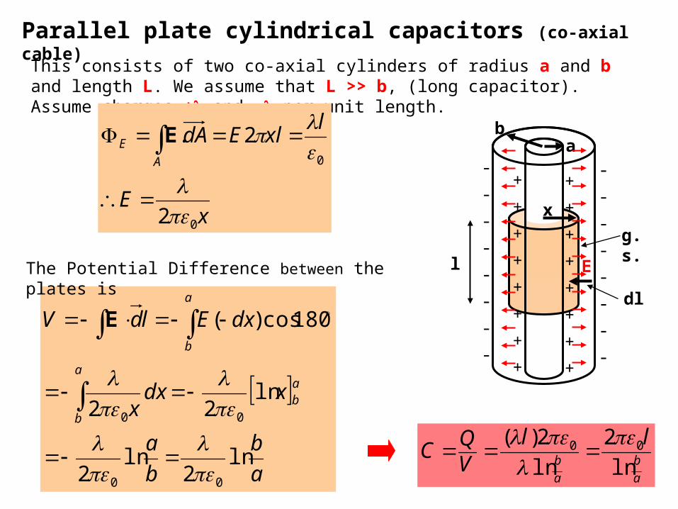
Parallel plate cylindrical capacitors (co-axial cable)
This consists of two co-axial cylinders of radius a and b and length L. We assume that L >> b, (long capacitor). Assume charges + and - per unit length.
-
-
-
-
-
-
-
-
+
+
+
+
+
+
+
+
-
-
-
-
-
-
-
-
+
+
+
+
+
+
+
+
l
ba
x
E
dl
g.s.
2
2.
0
0
xE
lxlEdA
A
E
E
a
b
b
a
xdxx
dxEldV
ab
a
b
a
b
ln2
ln2
ln22
180cos)(
00
00
E
a
b
a
b
llVQ
Cln
2
ln
2)( 00
The Potential Difference between the plates is
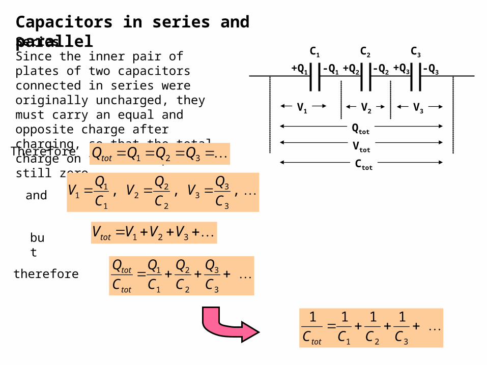
Capacitors in series and parallel
+Q1 +Q2 +Q3-Q1 -Q2 -Q3
C1 C2 C3
V2 V3V1
Qtot
Ctot
Vtot
SeriesSince the inner pair of plates of two capacitors connected in series were originally uncharged, they must carry an equal and opposite charge after charging, so that the total charge on the inner plates is still zero.
Therefore 321 QQQQtot
and , , ,3
33
2
22
1
11 C
QV
C
QV
C
QV
but 321 VVVVtot
therefore 3
3
2
2
1
1 C
Q
C
Q
C
Q
C
Q
tot
tot
111
1
321
CCCCtot
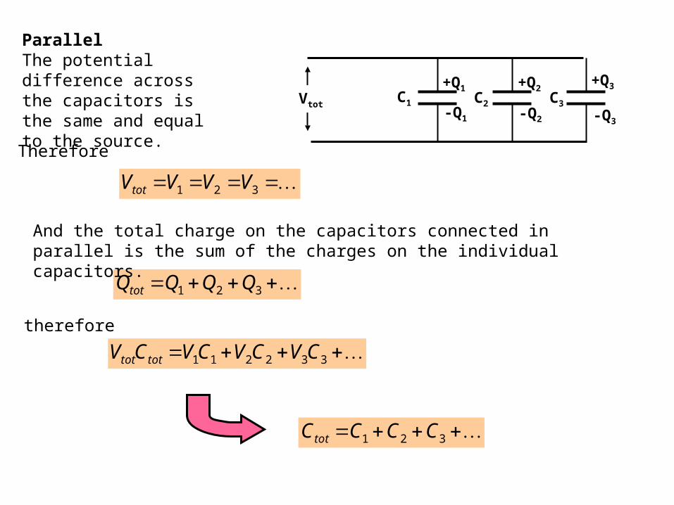
ParallelThe potential difference across the capacitors is the same and equal to the source.
Therefore
321 QQQQtot
And the total charge on the capacitors connected in parallel is the sum of the charges on the individual capacitors.
321 VVVVtot
therefore
+Q1 +Q2+Q3
-Q1 -Q2 -Q3
C1 C2 C3Vtot
332211 CVCVCVCV tottot
321 CCCCtot

Energy of a charged capacitor
The electrical potential energy stored in a charged capacitor corresponds to the work done in charging the capacitor. The energy is stored in the electric field between the plates of the capacitor.Suppose that a charge q has been transferred during the charging of a capacitor.
C
qV Potential difference across capacitor
Therefore the work done by the battery in (external agent) in transferring a small additional charge dq is
dqC
qVdqdW
The total work required to charge the capacitor from q=0 to some charge q=Q is
C
Qdq
C
qdWW
Q
2
2
0
This work required to charge the capacitor appears as a stored electrical potential energy
22
2
1
2
1
2CVQV
C
QU
22
2
1
2
1
2CVQV
C
QU
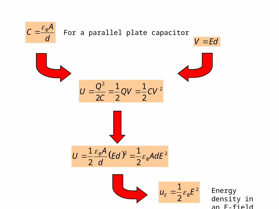
d
AC 0
EdV For a parallel plate capacitor
20
20
2
1
2
1AdEEd
d
AU
202
1EuE Energy density
in an E-field
Uses of Capacitors
Capacitors are used in most electronic circuits.(Usually related to the storage of electrical energy.)
Smoothing the direct current output of rectifier circuits. Switching of high currents in electric power applications.
When capacitors and resistors are used in combination, the circuit has a characteristic time constant.
Noise filters when the signal and the noise are in different frequency bands. Tuning a radio to a particular frequency (using the idea of resonance).
Modern switching devices (e.g. computer keyboards).
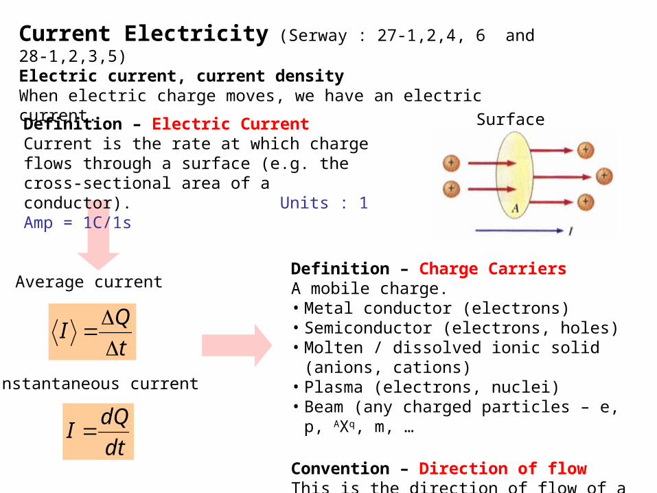
Current Electricity (Serway : 27-1,2,4, 6 and 28-1,2,3,5)Electric current, current densityWhen electric charge moves, we have an electric current.
Definition – Charge Carriers A mobile charge.• Metal conductor (electrons)• Semiconductor (electrons, holes)• Molten / dissolved ionic solid (anions, cations)• Plasma (electrons, nuclei)• Beam (any charged particles – e, p, AXq, m, …
Convention – Direction of flowThis is the direction of flow of a positive charge
carrier
Surface
Average current
Instantaneous current
t
QI
dt
dQI
Definition – Electric CurrentCurrent is the rate at which charge flows through a surface (e.g. the cross-sectional area of a conductor). Units : 1 Amp = 1C/1s
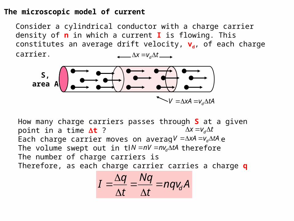
The microscopic model of current
Consider a cylindrical conductor with a charge carrier density of n in which a current I is flowing. This constitutes an average drift velocity, vd, of each charge carrier.
tvx d
tAvxAV d
S,area A
How many charge carriers passes through S at a given point in a time t ? Each charge carrier moves on average a distanceThe volume swept out in this time is thereforeThe number of charge carriers isTherefore, as each charge carrier carries a charge q
tvx dtAvxAV d
tAnvnVN d
Anqvt
Nq
t
qI d

Current
Current density
AnqvI d
dnqvA
IJ
Charge on each carrier
Density of charge carriers(Number of charge carriers
per unit volume)
Average drift speed
Drift velocity explainedConsider an isolated conductor in which the charge
carriers are free electrons. These electrons undergo random motion, with many collisions amongst each other and with the metal ions, somewhat analogous to the molecules in a gas.
The motion is rapid and erratic but does not lead to any overall motion of charge.
When a potential difference is applied to the ends of the conductor, there is an overall tendency for the electrons to move to the region of lower potential.
The average motion is the drift velocity, vd.Question : Why is each inter-collision segment parabolic ?
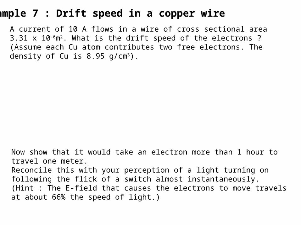
Example 7 : Drift speed in a copper wire
A current of 10 A flows in a wire of cross sectional area 3.31 x 10⁻⁶m2. What is the drift speed of the electrons ? (Assume each Cu atom contributes two free electrons. The density of Cu is 8.95 g/cm3).
Now show that it would take an electron more than 1 hour to travel one meter.Reconcile this with your perception of a light turning on following the flick of a switch almost instantaneously. (Hint : The E-field that causes the electrons to move travels at about 66% the speed of light.)

Ohm’s Law and resistance
dnqvJ The current density is usually considered a vector quantity
Ohm’s Law (established by experiment) For most metals, and some other materials, the ratio of current density to electric field is a constant , where is independent of the electric field producing the current.
EJ Current density
Conductivity - the constant of proportionality
Electric field
σρ
1
Ohmic Materials are materials which obey Ohm’s Law
Resistivity is the inverse of conductivity
Consider the E-field E to be due to a
potential difference V over a length l, and note the relation of current I to current J density. (Recover the form V=IR.)
IRA
lIV
l
ΔVσσE
A
IJ
So
A
l
A
lR
l
RAand
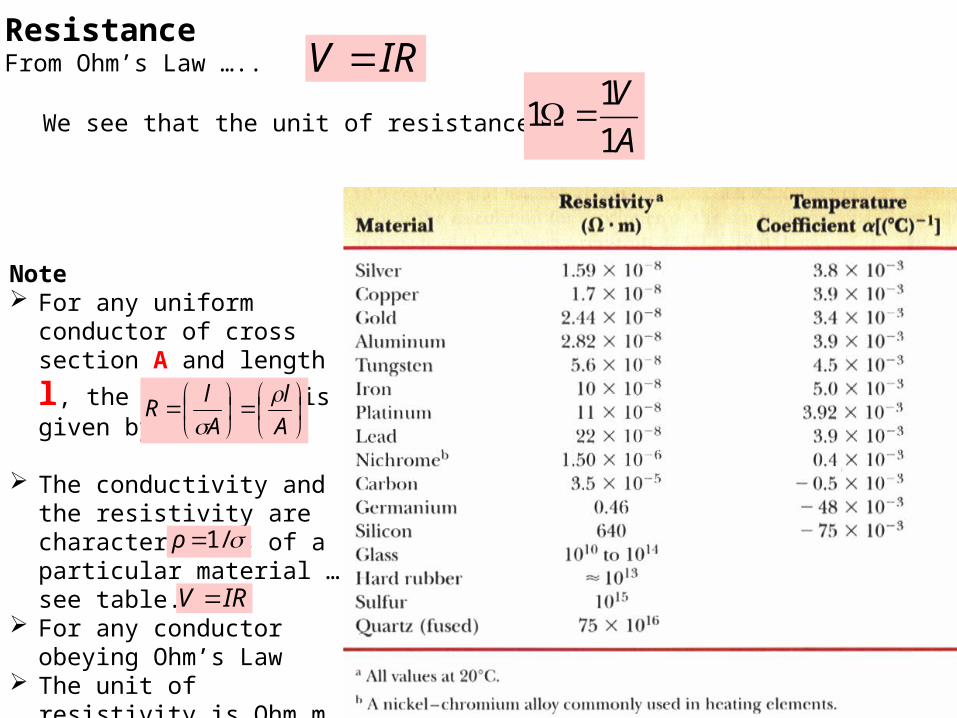
Note For any uniform conductor
of cross section A and
length l, the resistance is given by
The conductivity and the resistivity are characteristics of a particular material … see table.
For any conductor obeying Ohm’s Law
The unit of resistivity is Ohm.m (.m)
ResistanceFrom Ohm’s Law ….. IRV
We see that the unit of resistance isA
V
1
11
IRV
/1ρ
A
l
A
lR

Resistivity and conductivity; temperature variation
It is found that resistivity changes with temperature T.To a good approximation, resistivity varies linearly with temperature T.
00 1 TT
is called the temperature coefficient of resistivity.
0 and T0 represent the reference resistivity and temperature usually Room Temperature values.
Rearranging the equation to show ...
0
0
00
11
TTT
For metals, (T) is linear until very low temperatures where it levels off
For the three Group IV semiconductors in the previous table, is negative, showing that (T) decreases with increasing temperature as more charge carriers become available
T 0
met
alsSemi-conductors

The units of are °C-1 or K-1
The resistance of a resistor also varies linearly with temperature according to a similar equation (show this) …
00 1 TTRR
ApplicationThe platinum resistance thermometer – when immersed in a temperature bath, the resistance changes by a known amount, allowing the temperature to be calculated.
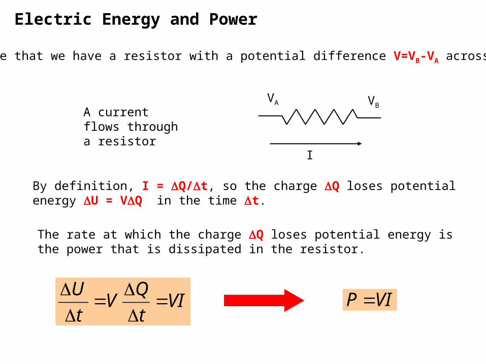
Electric Energy and Power
Suppose that we have a resistor with a potential difference V=VB-VA across it.
I
VA VBA current flows through a resistor
By definition, I = Q/t, so the charge Q loses potential energy U = VQ in the time t.
The rate at which the charge Q loses potential energy is the power that is dissipated in the resistor.
VIt
QV
t
U
VIP

Electric Energy and Power
The energy that is lost by the charge U = VQ is dissipated in the resistor and appears as heat energy.
Using Ohm’s Law.
R
VP
RIP
VIP
2
2
IRV
We can show …..
Low resistance copper cable is expensive. Power utilities therefore use higher resistance cheaper cables.
There will be less power dissipated as heat if electrical energy is transported at high voltage (up to 765 kV).
This is also known as Joule Heat that is dissipated in R
+-
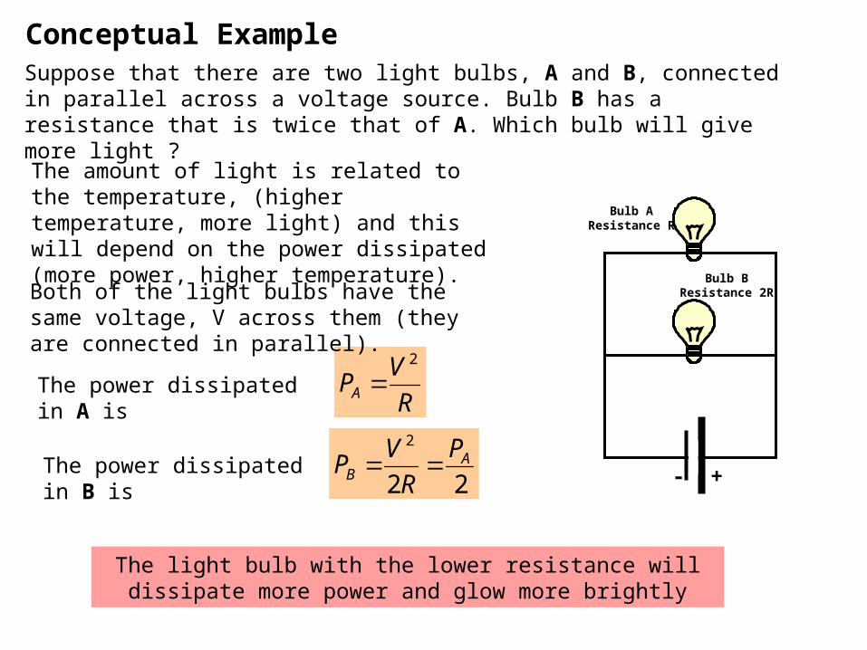
Conceptual ExampleSuppose that there are two light bulbs, A and B, connected in parallel across a voltage source. Bulb B has a resistance that is twice that of A. Which bulb will give more light ?
The amount of light is related to the temperature, (higher temperature, more light) and this will depend on the power dissipated (more power, higher temperature).
R
VPA
2
Both of the light bulbs have the same voltage, V across them (they are connected in parallel).
The power dissipated in A is
22
2A
B
P
R
VP The power dissipated in B is
The light bulb with the lower resistance will dissipate more power and glow more brightly
Bulb AResistance R
Bulb BResistance 2R
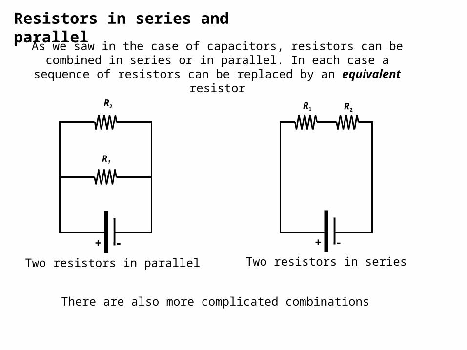
Resistors in series and parallel
As we saw in the case of capacitors, resistors can be combined in series or in parallel. In each case a sequence of resistors can be replaced by
an equivalent resistor
+ - + -
R1
R2 R2R1
Two resistors in seriesTwo resistors in parallel
There are also more complicated combinations

Combining resistors in parallel
We wish to find an equivalent resistor that will have the same effectas two resistors in parallel.
+ -
Req
What is Req in terms of R1 and R2 ?
=
+ -
R1
R2

Combining resistors in parallelNote • The potential difference across both resistors must be the same.• The current must branch at the parallel junction. • Ohm’s law applies to each resistor, as well as to the circuit.
Req in terms of parallel resistors ….
+ -
V1 , R1
V2 , R2
I = I1 + I2
I2
I1
21 VVV
21 III
2
2
1
1
R
V
R
V
R
V
eq
21
111
RRReq
V
......1111
321
RRRReq
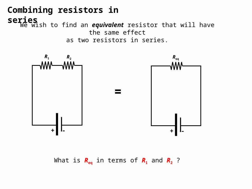
Combining resistors in series
We wish to find an equivalent resistor that will have the same effectas two resistors in series.
+ -
Req
What is Req in terms of R1 and R2 ?
=
+ -
R2R1

Combining resistors in seriesNote • In this case, the current through each resistor must be the same.• The potential difference at each resistor must equal the total voltage. • Ohm’s law applies to each resistor, as well as to the circuit.
Req in terms of series resistors ….
21 III
21 VVV
2211 RIRIIR
+ -
R2R1
I1 I2
I
V1 V2
V
21 RRR
......221 RRRR
Electromotive force and terminal voltage
A source of electrical energy in a circuit, such as a battery (or a generator) is said to provide an emf or electromotive force (although it’s
a source of energy, not force)
The battery, so to speak, pumps the charge up to a higher potential.
Then, if there is a path for it, the charge flows around the external circuit as an electric current.
The unit of emf is therefore the volt (V).
The emf is the work done per unit charge. It has the same units as electric potential.

Internal Resistance
From the circuit it is clear that the current flows through the battery too, and that a battery also has an internal resistance.
A real battery therefore has a source emf
called and an internal resistance r.
When connected to a load resistance R, so that a current I flows through the circuit, the terminal voltage of the battery is therefore
Source emf Real battery Internal resistance r
IrV
The emf called and can be measured in the so-called open circuit voltage mode, when the battery is not connected to a load resistance, and a voltmeter which requires negligible current to operate is used.

Internal ResistanceThe terminal voltage across the battery depends on the current that is being drawn.
R is the resistance of the load resistance (a resistor, or a device like a toaster, TV, heater etc …). Clearly
IRV
IrV
rRI
IRV
Battery with emf and internal resistance r.
Terminal voltage
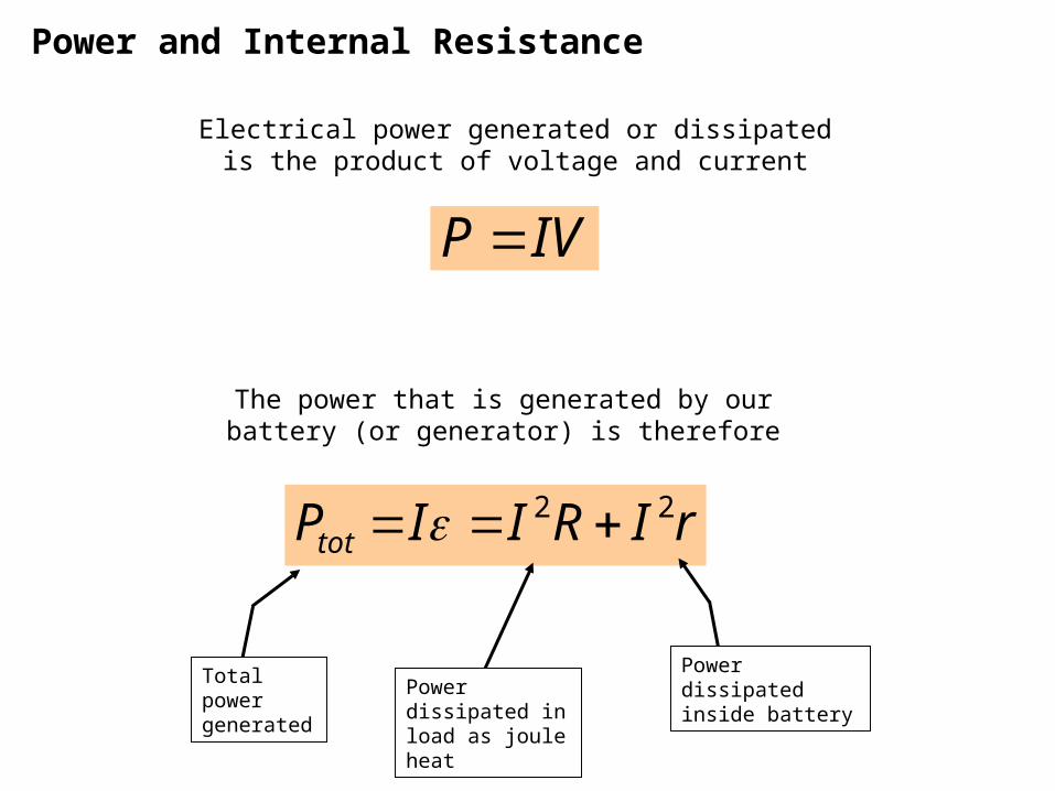
Power and Internal Resistance
Electrical power generated or dissipated is the product of voltage and current
The power that is generated by our battery (or generator) is therefore
IVP
rIRIIPtot22
Total power generated
Power dissipated inside batteryPower dissipated
in load as joule heat

Power transferred to the load resistance
In this circuit, some of the power P is delivered to the load, while some is lost inside the battery.
We would like to deliver as much power as possible to the load.
Is there an optimal value of load resistor R to achieve this ?
RrR
RIRPload
2
2
)()(
Answer

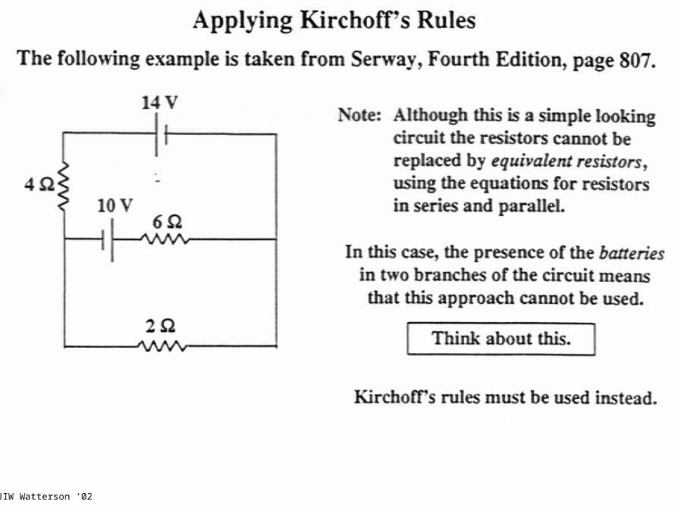
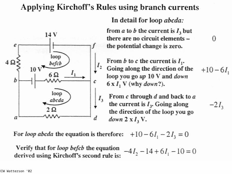
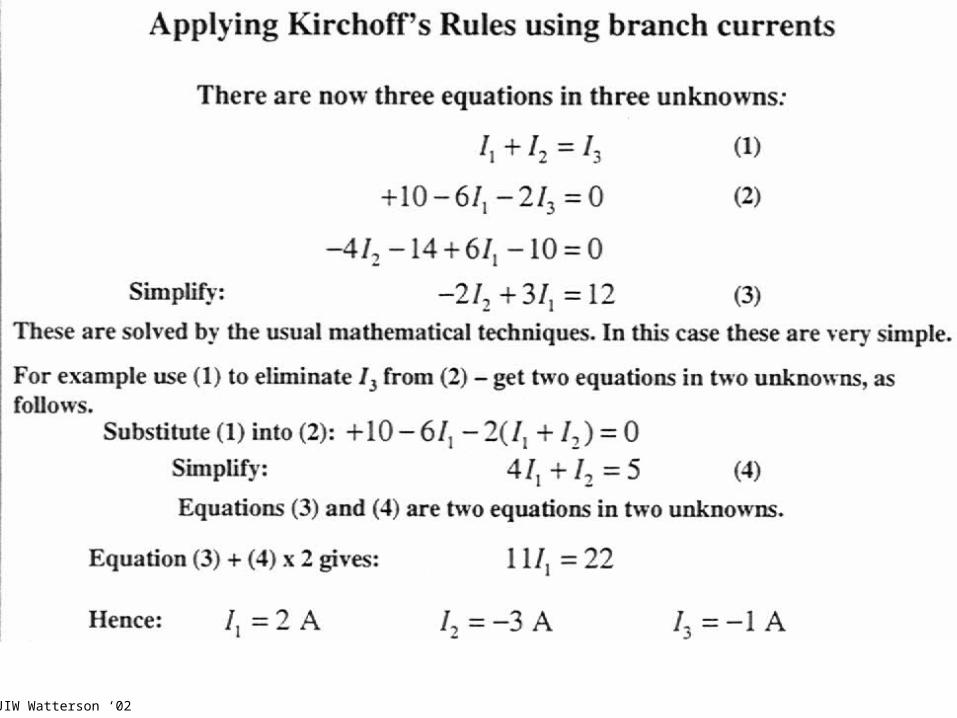
Kirchoff’s laws and their applicationsOften it is not possible to reduce a circuit to a single loop, using the rules for the combination of series and parallel resistors alone.
They can however be further analysed using the Kirchoff’s voltage and current Laws.
We will restrict ourselves to “resistive circuits” which contain only resistors and sources.
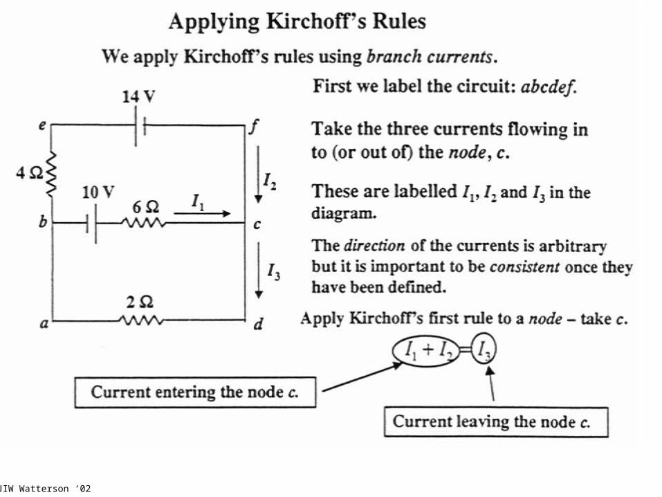
Kirchoff’s Current Law (Kirchoff’s First Law)The algebraic sum of the currents entering any node (junction) must equal the sum of currents leaving the junction.
321 III
This is a statement of the fact that charge is conserved. In a steady state circuit, there can be no build-up of charge, therefore the current is conserved.
outin III2
I3
I1
+- +
-
Redrawn equivalent circuit showing two joined nodes are actually a single node with four legs
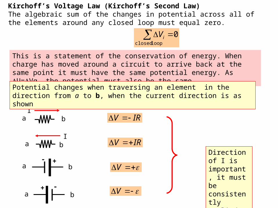
Kirchoff’s Voltage Law (Kirchoff’s Second Law)The algebraic sum of the changes in potential across all of the elements around any closed loop must equal zero.
This is a statement of the conservation of energy. When charge has moved around a circuit to arrive back at the same point it must have the same potential energy. As U=Vq, the potential must also be the same.
0loop closed
iV
Ia b
Ia b
- +
a b
-+
a b
IRV
IRV
V
V
Direction of I is important, it must be consistently applied.
Potential changes when traversing an element in the direction from a to b, when the current direction is as shown
JIW Watterson ‘02
JIW Watterson ‘02

JIW Watterson ‘02
JIW Watterson ‘02
JIW Watterson ‘02

JIW Watterson ‘02
JIW Watterson ‘02

JIW Watterson ‘02
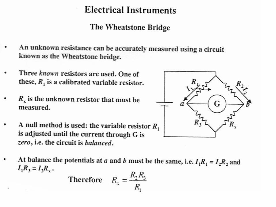
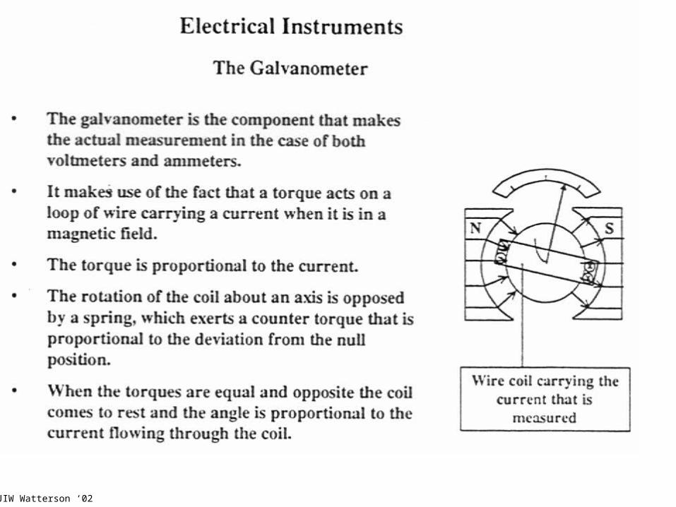
Ammeters and voltmeters, determination of resistanceSerway 28-5

JIW Watterson ‘02
JIW Watterson ‘02