
114
Z-Class electric pumps are designed for use in
the harshest manufacturing environments. The
pumps provide reliable and durable performance in a
wide variety of configurations.
Electric pumps Application & selection Shown: ZW5020HE-FT22
Pump type Valve/manifold type Motor voltage
50/60 Hz
230 VAC, 3 ph
230 VAC, 3 ph
230 VAC, 3 ph
230 VAC, 3 ph
230 VAC, 3 ph
115 VAC, 1 ph230 VAC, 3 ph
460 VAC, 3 ph
115 VAC, 1 ph
230 VAC, 3 ph
460 VAC, 3 ph
115 VAC, 1 ph
230 VAC, 3 ph
460 VAC, 3 ph
The standard for workholding applications•FeaturesZ-Classhigh-efficiencypumpdesign;higheroilflowandby-passpressure,coolerrunningandrequires18%lesscurrentthancomparablepumps
•Totallyenclosed,fancooledindustrialelectricmotorssupplyextendedlifeandstanduptoharshindustrialenvironments
•Multiplevalveandreservoirconfigurationsprovideapplicationspecificmodelstomatchthemostdemandingworkholdingapplications
•High-strength,moldedelectricalenclosureprotectselectronics,powersuppliesandLCDreadoutfromcoolantandcontamination.
Basic configurationsAll pumps listed in this chart include LCD electrical box, 20 litres reservoir, return line filter and either 0-420 bar pressure gauge or pressure transducer (solenoid valve models). For additional options, see the complete pump matrix on page 117.
Pressure and tank ports
Single station DO3
Enerpac VP-series
Two station DO3
Four station DO3
4-way, 3-pos. solenoid operated4-way, 3-pos. solenoid operated
4-way, 3-pos. solenoid operated
4-way, 3-pos. solenoid operated
4-way, 3-pos. solenoid operated
4-way, 3-pos. solenoid operated
4-way, 3-pos. manually operated
4-way, 3-pos. manually operated
4-way, 3-pos. manually operated
ZW-Series with manifold• Used when supplying pressure to multiple valve circuits• Valves must be supplied separately.
ZW-Series with pallet coupling valve• Provides momentary pressure and flow to fixture• Ideal for pallet disconnect systems.
ZW-Series with continuous connection valve• Provides solenoid control of one single or
double-acting circuit• Control valve supplied with integrated pilot operated
check to ensure positive pressure holding.
ZW-Series with manual valve• Provides manual control of one single or
double-acting circuit• Control valve supplied with center holding function to
ensure positive position holding.
Colle
t-Lo
k® p
rodu
cts
Swin
g cl
amps
Wor
k S
uppo
rtsLi
near
Cyl
inde
rsPo
wer
Sou
rces

www.enerpacwh.com 115
Flow rate: 0,54 - 1,64 l/min
Pressure: 350 bar max
Motor: 0,75 - 1,12 kW
Reservoir: 8-40litres
E Bombas eléctricas
F Centrale hydraulique
D Tauchpumpe
Output oil flow versus hydraulic pressure
Single-stage pumps provide constant flow throughout the entire pressure range via a radial piston pump.
Two-stage pumps provide high flow via a gear pump
until the bypass pressure is reached. At pressures above the bypass setting, the radial piston pump provides flow to
the maximum pressure.
LCDelectricalpackageisrequiredforpumpsutilizingelectric valves, or optional accessories such as the
pressure transducer, level switch, pressure switch
or heat exchanger.
All Z-Class electric pumps are CSA and CE compliant.
LCD Electric Model Nr.LCD Electric Model Nr. LCD Electric Model Nr.
ZW4 Series Output oil flow at
0,82 l/min at 350 bar
ZW3 Series Output oil flow at
0,54 l/min at 350 bar
ZW5 Series Output oil flow at
1,64 l/min at 350 bar
Important
ZW-series
Power Sources
Pallet Components
ValvesSystem
Components
Yellow Pages
ZW3 – Oil flow vs hydraulic pressure ZW4 – Oil flow vs hydraulic pressure
ZW5 – Oil flow vs hydraulic pressure
Oil fl
ow (l
/min
) ▶
Oil fl
ow (l
/min
) ▶
Oil fl
ow (l
/min
) ▶
Hydraulic pressure (bar) ▶ Hydraulic pressure (bar) ▶
Hydraulic pressure (bar) ▶
Two stageSingle stageTwo stage
Single stageTwo stage
ZW4020HG-FW01
ZW4020HG-FW11
ZW4020HG-FW12
ZW4020HG-FW21
ZW4020HG-FW41
ZW4420DB-Ft
ZW4420DE-Ft
ZW4420DW-Ft
ZW4420FB-Ft
ZW4420FE-Ft
ZW4420FW-Ft
ZW4420LB-FG
ZW4420LE-FG
ZW4420LW-FG
ZW3020HG-FE01
ZW3020HG-FE11
ZW3020HG-FE12
ZW3020HG-FE21
ZW3020HG-FE41
ZW3420DB-Ft
ZW3420DE-Ft
ZW3420DW-Ft
ZW3420FB-Ft
ZW3420FE-Ft
ZW3420FW-Ft
ZW3420LB-FG
ZW3420LE-FG
ZW3420LW-FG
ZW5020HG-FW01
ZW5020HG-FW11
ZW5020HG-FW12
ZW5020HG-FW21
ZW5020HG-FW41
ZW5420DB-Ft
ZW5420DE-Ft
ZW5420DW-Ft
ZW5420FB-Ft
ZW5420FE-Ft
ZW5420FW-Ft
ZW5420LB-FG
ZW5420LE-FG
ZW5420LW-FG
116
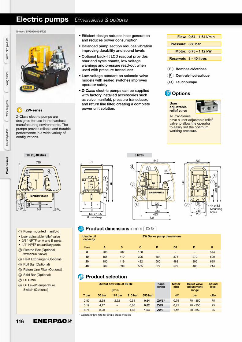
Shown: ZW5020HE-FT22
Electric pumps Dimensions & options
User adjustable relief valve
All ZW-Series have a user adjustable relief valve to allow the operator to easily set the optimum working pressure.
Flow: 0,54 - 1,64 l/min
Pressure: 350 bar
Motor: 0,75 - 1,12 kW
Reservoir: 8-40litres
Outputflowrateat50Hz Pump Motor ReliefValve Sound series size adjustment level (l/min) range
7 bar 50 bar 115 bar 210 bar 350 bar kW bar dBA
•Efficientdesignreducesheatgenerationandreducespowerconsumption
•Balancedpumpsectionreducesvibrationimprovingdurabilityandsoundlevels
•Optionalback-litLCDreadoutprovideshourandcyclecounts,lowvoltagewarningsandpressureread-outwhenusedwithpressuretransducer
•Low-voltagependantonsolenoidvalvemodelswithsealedswitchesimprovesoperatorsafety
•Z-Classelectricpumpscanbesuppliedwithfactoryinstalledaccessoriessuchasvalvemanifold,pressuretransducer,andreturnlinefilter,creatingacompletepowerunitsolution.
E Bombas eléctricas
F Centrale hydraulique
D Tauchpumpe
①Pump mounted manifold
• User adjustable relief valve • 3/8" NPTF on A and B ports • 1/4" NPTF on auxiliary ports
②Electric Box (Optional w/manual valve)
③Heat Exchanger (Optional)
④Roll Bar (Optional)
⑤Return Line Filter (Optional)
⑥Skid Bar (Optional)
⑦Oil Drain
⑧Oil Level/Temperature Switch (Optional)
Usable oil ZW Series pump dimensions capacity
litres A B C D D1 E H
4x ø 8,6Mounting holes
M8 x 1,25 6 mm deep
Options
Product selection
Product dimensions in mm [ ]
10, 20, 40 litres 8 litres
* Constant flow rate for single-stage models.
ZW-series
Z-Class electric pumps are designed for use in the harshest manufacturing environments. The pumps provide reliable and durable performance in a wide variety of configurations.
2,80 2,68 2,32 0,54 0,54 ZW3 * 0,75 70 - 350 75
5,19 4,17 − 0,86 0,82 ZW4 0,75 70 - 350 75
8,74 8,23 − 1,68 1,64 ZW5 1,12 70 - 350 75
Colle
t-Lo
k® p
rodu
cts
Swin
g cl
amps
Wor
k S
uppo
rtsLi
near
Cyl
inde
rsPo
wer
Sou
rces
8 206 287 168 - - - 574
10 155 419 305 384 371 279 599
20 180 419 422 500 488 396 625
40 269 399 505 577 572 480 714

www.enerpacwh.com 117
ZW-series, Electric Pump ordering matrix
Flow: 0,54 - 1,64 l/min
Pressure: 350 bar
Motor: 0,75 - 1,12 kW
Reservoir: 8-40litres
E Bombas eléctricas
F Centrale hydraulique
D ModulareSpannpumpe
ZW4020GE-FGS21 is a 0,82 l/min, single-stage pump with a 2 station D03 manifold, standard electric without LCD, 20 litres reservoir, 230 volt, 50/60 Hz motor, return line filter and 0-420 bar pressure gauge.
Example
ZW4410DW-T is a 0,82 l/min, 2-stage pump with a pallet de-coupling valve, LCD electrical box, 10 litres reservoir, 380-415 volt 3-phase motor and pressure transducer.
ZW5040HG-FGL01 is a 1,64 l/min, 2-stage pump with a pressure and tank manifold, LCD electrical box, 40 litres reservoir, 230 Volt 3-phase motor, return line filter, 0-420 bar pressure gauge and level and temperature shutdown switch.
The ZW5810LG-FT is a 1,64 l/min, 2-stage pump with a manual 4-way, 3 position tandem center valve, integrated P.O. check, LCD electrical box, 10 litres reservoir, 208-240 volt 3-phase motor, return line filter and pressure transducer.
Example
1 Product type Z = Z-Class Pump
2 Motor type W = Workholding Electric
3 Flow group 3 = 0,54 l/min 4 = 0,82 l/min 5 = 1,64 l/min
4 Valve type 0 = No valve or valve manifold 2 = 3-way, 2-position, manual valve 3 = 3-way, 3-position, manual valve 4 = 4-way, 3-position, manual or
solenoid valve 6 = 3-way, 3-position, tandem center w/P.O. check (manual only) 8 = 4-way, 3-position, tandem center w/P.O. check (manual only)
5 Usable oil capacity 8 = 8 litres (2 gallon) 10 = 10 litres (2,5 gallon) 20 = 20 litres (5 gallon) 40 = 40 litres (10 gallon)
6 Valve operation D = Solenoid valve (pallet coupling) with
pendant and LCD (valve type 4) F = Solenoid valve (continuous
connection) with pendant and LCD (valve type 4)
G = Valve manifold without LCD (valve type 0) H = Valve manifold with LCD
(valve type 0) L = Manual valve with LCD (without
pendant, valve type 2, 3, 4, 6 or 8) M = Manual valve without LCD (valve type
2, 3, 4, 6 or 8) N = No valve, without LCD (valve type 0) W = No valve with LCD (valve type 0)
7 Power supply SinglePhase
B = 115V, 1 ph, 50-60 Hz 3
E = 208-240V, 1 ph, 50-60 Hz European plug I = 208-240V, 1 ph, 50-60 Hz USA plug ThreePhase
M = 190-200V, 3 ph, 50/60 Hz G = 208-240V, 3 ph, 50/60 Hz W = 380-415V, 3 ph, 50/60 Hz K = 440V, 3 ph, 50/60 Hz J = 460-480V, 3 ph, 50/60 Hz R = 575V, 3 ph, 50/60 Hz
8 Options*2
F = Return line filter, 25 micron G = 0-420 bar pressure gauge, 63,5 mm 5
H = Heat exchanger 4
L = Level/temperature switch 4
N = No handles (lifting eyes only) 2
P = Pressure switch 4
R = Roll bars S = Single stage T = Pressure transducer 4
U = Foot switch 4
9 Manifold options 5 (Pump types G and H only)
01 = Pressure & tank porting manifold 11 = Single station D03 12 = VP series manifold 13 = Single station CETOP 21 = 2 station D03 22 = 2 station CETOP 41 = 4 station D03 42 = 4 station CETOP
1 2 3 4 5 6 7 8 9 Product Motor Flow Valve Usable Valve Voltage Options 1 Manifold Type Type Group Type Oil Operation Options Capacity
1 Options should be specified in alphabetical order.
2 Unless specified, all pumps are supplied with reservoir handles.
3 115 volt pumps are supplied with CE and CSA approved 15 Amp plug for intermittent use. 20 Amps circuit recommended for frequent full pressure use.
4 These options require LCD electrical package.5 Pressure gauge not available on pump
models with pressure transducer. Pressure transducer provides digital pressure readout on LCD display.
6 Pressure switch option is only used as input to a customer control. It is not used with the LCD electrical package.
Custom build your pump
▼ This is how a ZW-series Model number is built:
Power Sources
Pallet Components
ValvesSystem
Components
Yellow Pages

118
Options PF-25replacementfilter element
Extend life of hydraulic components …increase system reliability
•25micronnominalfiltercleansoiltoincreasesystemlife
•Internalbypassvalvetopreventdamageifthefilterisdirty
•Allinstallationcomponentsincluded
•KitassemblesquicklyandeasilytoEnerpacpumpandmanifold
•Maintenanceindicatorincluded
E Filtro
F Filtre
D Filter
Max. flow: 45,4 l/min
Pressure: max. 13,8 bar
Filtration: 25 micron
Returnlinefilter ZPF-series
ZPF series
The oil filter kit removes contaminants from the return oil flow before allowing it back into the reservoir, reducing component damage.
Shown: ZPF
Nominal Model Maximum Maximum Bypass Filter filtration number pressure oil flow pressure gauge setting service indicator micron bar l/min bar kg
Product selection
For best performance,replace filter element on
a regular basis. Change filters when changing oil
or four times a year, whichever comes first.
Colle
t-Lo
k® p
rodu
cts
Swin
g cl
amps
Wor
k S
uppo
rtsLi
near
Cyl
inde
rsPo
wer
Sou
rces
Pressure drop vs oil flow
Aver
age
pres
sure
dro
p (l/
min
) ▶
Oil flow (l/min) ▶
25 ZPF 13,8 45,4 1,7 • 1,5

www.enerpacwh.com 119
E Intercambiador de calor
F Échangeur de chaleur
D Wärmetauscher
Heatexchangerkits ZHE-series
Extends system life•Electricalconnectorfactoryinstalled•Allinstallationcomponentsincluded•Stabilizesoiltemperatureatamaximumof54°Cat21°Cambienttemperature
•Stabilizesoilviscosity,increasingoillifeandreduceswearofpumpandotherhydrauliccomponents
Voltage: 24V
Pressure: max. 21 bar
Transfer: 900 Btu/h
ZHEseries
Heat exchanger removes heat from the return oil to provide cooler operation.
Shown: ZHE-E10
Voltage Model Thermal Amperage Maximum Maximum number transfer* draw pressure oil flow VDC Btu/h kJoule A bar l/min kg
Product selection
*At 1,9/min and ambient temperature of 21º C.
Important ZHE-SeriesHeatExchangers
Heat exchanger stabilizes oil temperature at 54⁰ C at 21⁰ C
ambient temperature. Thermal transfer at 19 l/min and
21⁰ C ambient temperature: 900 Btu/hour.
Donotexceedmaximumoil flow of 26,5 l/min and
maximum pressure of 20,7 bar. Not suitable for water-glycol or
high water based fluids.
Power Sources
Pallet Components
ValvesSystem
Components
Yellow Pages
Pressure drop vs oil flow
Pres
sure
dro
p (l/
min
) ▶
Oil flow (l/min) ▶
24 ZHE-E10 900 950 0,95 21 26,5 4,0

120
PT
ZLS series
Oil level indicator for pump reservoir. If the pump is mounted in a remote area that does not provide visual access to the external oil level sight glass, the level/temp switch will turn off the pump before internal damage can occur due to cavitations.
Shown: ZPT-U4, ZPS-W4
ZPT-series
ZPT pressure transducer provides constant pressure monitoring for automated pump control.
ZPS-series
ZPS pressure switch can be used to provide a pressure signal to an external control.
Note: Electrical harness included with kit. ZPS-W4 includes 0-420 bar pressure gauge.
Adustable Electrical Model Accuracy Deadband pressure specification number (full scale) range bar bar kg
▼ Mechanical adjustment
Fixed Model Voltage Thermostat Maximum temperature number rating setting pressure signal oC VDC Amps bar kg
Level/temp switch & pressure transducer ZLS, ZPT-series
Electronic level/temperature switch for feedback on pump oil level•Drop-indesignallowsforeasyinstallationtopumpreservoir
•Electricalconnectorincluded
•Built-inthermalsensingprovidesfeedbackonoiltemperature
•Senseslowoillevelinpumpreservoir.
Control your pump, monitor pressureZPT pressure transducer
•Moredurablethananaloggauges(againstmechanicalandhydraulicshock)
•Moreaccuratethananaloggauges(0,5%fullscale)
•Calibrationcanbefinetunedforcertification
•“Auto-mode”providesautomaticpressuremake-up
•Displaypressureinpsi,barorMPa
ZPS pressure switch
•Includesglycerinfilledgauge,G2536L
•Canbeusedtoprovidepressureinputtocustomerprovidedcontrols
•NottobeusedwithLCDcontrol
•ForpressurebasedinputtotheLCDcontrol,usetheZPT-U4transducer.
E Presión transductor
F Pressostats
D Druckschalter
Voltage: 24VDC
Temp. set point: 80° C
E Indicador del nivel/temp.
F Interrupteur de niveau/temp.
D Ölstand/Temperaturschalter
The pressure transducer isfactoryinstalledinthe“A”port on pumps supplied with valves,andinthe“P”porton
models with manifolds.
Product Selection
Product Selection
Voltage: 115VAC/24VDC
Pressure: 3,5 - 700 bar
Important
3,5 - 700 4-20 mA ZPt-u4 0,5 % 3,5 0,13
35 - 700 115 VAC /24 VDC N.O. ZPS-W4 2,0 % 8 - 40 1,22
Shown: ZLS-U4
Colle
t-Lo
k® p
rodu
cts
Swin
g cl
amps
Wor
k S
uppo
rtsLi
near
Cyl
inde
rsPo
wer
Sou
rces
80 ZLS-u4 24 2,6 10 0,05

www.enerpacwh.com 121
120▸
120▸
Valve manifolds ZW-series
E Colectores
F Manifolds
D Verkettungsblöcke
Stations: 1-8 valves vertical
Stations: 1-4valveshorizontal
Pressure: 350 bar Increased flexibility for complex systems•Manifoldsprovidehydraulicconnectiontoremoteorpumpmountedvalves
•Usedwhenmultiplevalvesarerequiredforcontrollingseveralindependentcircuits
•Availablefor2and4stationD03aswellasEnerpacVPseriesmounting
•Pressureandtankportingmanifoldavailableforusewithremotevalvesticks
•Manifoldsincludeintegratedreliefvalveforsystempressurecontrol.
Product Selection
MB series
Manifolds allow the use of multiple valves powered by a single hydraulic pump. Manifolds are available factory installed on your Z-Class workholding power unit, or separately for future system upgrades.
❚ Enerpac porting manifold provides pressure and tank line to remote mounted valve stack on a machining center.
Valve mounting pattern Option code Number of Coverplate (see page 117) stations model number
0.250-18 NPTFgauge port
Options Pressure transducer
Level switch
3/8" tube (2x)(37 deg. flare)
Adjustable relief valve
0.375-18 NPTFtank port
Option 01 Option 12
Option 21, 41
VP11 Shown for reference only
#8 SAE (8x)0.750-16 UN
VMMD-001 Shown for reference only
Option 21 has two valve stationsOption 41 has four valve stations
Porting manifold, SAE ports 01 – –
Enerpac VP Series 12 1-8 –
2 station DO3 21 2 MC-1
4 station DO3 41 4 MC-1
2 station CETOP3 22 2 MC-3
4 station CETOP3 42 4 MC-3
Shown: MB-2, -4
Power Sources
Pallet Components
ValvesSystem
Components
Yellow Pages
122
ZW4410FE-FT
ZW4410FE-FT
AH652/AR650MV722B
SURD121
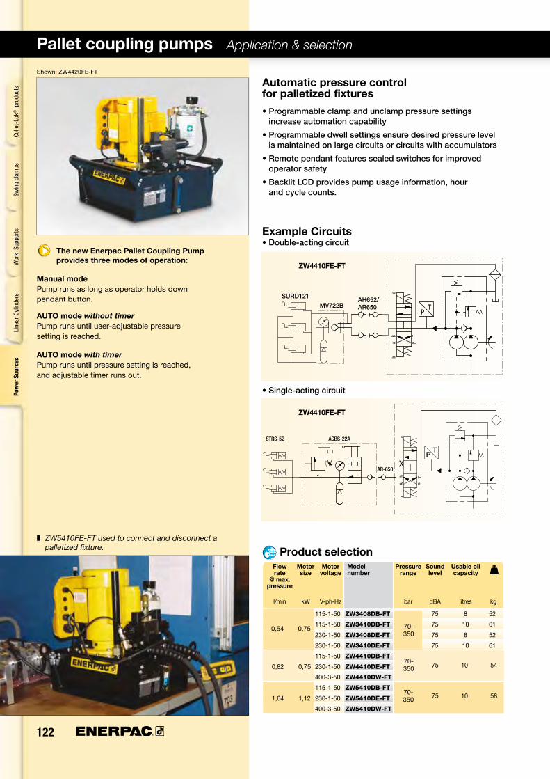
Pallet coupling pumps Application & selection
Automatic pressure control forpalletizedfixtures•Programmableclampandunclamppressuresettingsincreaseautomationcapability
•Programmabledwellsettingsensuredesiredpressurelevelismaintainedonlargecircuitsorcircuitswithaccumulators
•Remotependantfeaturessealedswitchesforimprovedoperatorsafety
•BacklitLCDprovidespumpusageinformation,hourandcyclecounts.
Example Circuits•Double-actingcircuit
•Single-actingcircuit
The new Enerpac Pallet Coupling Pump provides three modes of operation:
Manual modePump runs as long as operator holds down pendant button.
AUTO mode without timerPump runs until user-adjustable pressure setting is reached.
AUTO mode with timerPump runs until pressure setting is reached, and adjustable timer runs out.
Product selection
Shown: ZW4420FE-FT
Flow Motor Motor Model Pressure Sound Usable oil rate size voltage number range level capacity @ max. pressure l/min kW V-ph-Hz bar dBA litres kg
❚ ZW5410FE-FT used to connect and disconnect a palletized fixture.
115-1-50 ZW3408DB-Ft 75 8 52
115-1-50 ZW3410DB-Ft 75 10 61
230-1-50 ZW3408DE-Ft 75 8 52
230-1-50 ZW3410DE-Ft 75 10 61
115-1-50 ZW4410DB-Ft
0,82 0,75 230-1-50 ZW4410DE-Ft
400-3-50 ZW4410DW-Ft
115-1-50 ZW5410DB-Ft
1,64 1,12 230-1-50 ZW5410DE-Ft
400-3-50 ZW5410DW-Ft
0,54 0,75
Colle
t-Lo
k® p
rodu
cts
Swin
g cl
amps
Wor
k S
uppo
rtsLi
near
Cyl
inde
rsPo
wer
Sou
rces
70-350
70-350
75 10 54
70-350 75 10 58

www.enerpacwh.com 123
119▸
120▸
120▸
118▸
Options
Pressure: 350 bar
Flow: 0,54 - 1,64 l/min
Reservoir: 8,0-40,0litres
Heatexchanger
Level switch
Pressuretransducer
Returnlinefilter
For complete ordering matrix of all factory-installed options
see page 117.
Important Enerpac recommends
a pressure differential of no less than 14 bar for most
applications. If you believe your application requires a tighter differential, please
contact us directly.
Manual modeMotor and pump operate only when operator presses and holds the up (or down) arrow on the pendant. When button is released, pressure in the hoses is relieved.
AUTO mode With DWELL timer set equal to zero: operator starts the motor by pressing and holding the up (or down) arrow on the pendant. Pump builds to pressure on the clamp (or unclamp) circuit until it reaches customer programmed setting. The motor immediately turns off and pressure in the hoses is relieved.
With DWELL timer set greater than zero: operator starts the motor by pressing the up (or down) arrow on the pendant. Once the pump reaches the programmed setting, the DWELL timer starts. When the timer runs out, the motor stops and pressure in the hoses is relieved.
Operation – pallet coupling pump
Usable Model A B C D D1 E H oil number capacity kg
litres ZW3 ZW4 ZW5
Dimensions & options ZW-series
Output oil flow versus hydraulic pressure
Product dimensions in mm [ ]
10, 20, 40 litres 8 litres
Motor: 0,75 - 1,12 kW
Power Sources
Pallet Components
ValvesSystem
Components
Yellow Pages
4x ø 8,6Mounting holes
M8 x 1,25 6 mm deep
ZW3 – Oil flow vs hydraulic pressure ZW4 – Oil flow vs hydraulic pressure ZW5 – Oil flow vs hydraulic pressure
Oil fl
ow (l
/min
) ▶
Oil fl
ow (l
/min
) ▶
Oil fl
ow (l
/min
) ▶
Hydraulic pressure (bar) ▶ Hydraulic pressure (bar) ▶ Hydraulic pressure (bar) ▶
Two stageSingle stageTwo stage
Single stageTwo stage
8 ZWxx08xx 206 279 206 — — — 574 42 42 47
10 ZWxx10xx 155 412 305 384 371 279 599 49 49 52
20 ZWxx20xx 180 412 422 500 488 396 625 61 61 65
40 ZWxx40xx 269 399 506 577 572 429 714 84 84 87

124
ZW4410FI-FT
ZW4410FI-FT
Continuous connection pumps Application & selection
Automatic pressure control for continuous connection fixtures•Programmablepressuresettingallowspumptomaintainsystempressurecontinuously
•Includespilotoperatedcheckvalveensuringpressureismaintainedincircuit
•Z-Classhigh-efficiencypumpdesign;featuringhigheroilflowandby-passpressurethancomparablepumps
•High-strength,moldedelectricalenclosureprotectselectronics,powersuppliesandLCDreadoutfromharshindustrialenvironments.
Example Circuits•Double-actingcircuit
•Single-actingcircuit
The new Enerpac Continuous Connection Pump provides two modes of operation:
Manual modePump runs continuously, building pressure as long as operator holds down pendant button.
AUTO modePump runs continuously, maintaining user-set pressure window on clamp circuit as long as necessary.
Shown: ZW4420FE-FT
❚ ZW5410FE-FT used to control clamping cycle on a horizontal machining center. Product selection
Flow Motor Motor Model Pressure Sound Usable oil rate size voltage number range level capacity @ max. pressure l/min kW V-ph-Hz bar dBA litres kg
Colle
t-Lo
k® p
rodu
cts
Swin
g cl
amps
Wor
k S
uppo
rtsLi
near
Cyl
inde
rsPo
wer
Sou
rces
115-1-50 ZW3408FB-Ft 75 8 52
115-1-50 ZW3410FB-Ft 75 10 61
230-1-50 ZW3408FI-Ft 75 8 52
230-1-50 ZW3410FI-Ft 75 10 61
115-1-50 ZW4410FB-Ft
0,82 0,75 230-3-50 ZW4410FG-Ft
460-3-50 ZW4410FJ-Ft
115-1-50 ZW5410FB-Ft
1,64 1,12 230-3-50 ZW5410FG-Ft
460-3-50 ZW5410FJ-Ft
70-350
70-350
75 10 54
70-350 75 10 58
0,54 0,75

www.enerpacwh.com 125
119▸
120▸
120▸
118▸
Dimensions & options ZW-series
Options
Pressure: 350 bar
Flow: 0,54 - 1,64 l/min
Motor: 0,75 - 1,12 kW
Reservoir: 8-40litres
Heatexchanger
Level switch
Pressuretransducer
Returnlinefilter
For complete ordering matrix of all factory-installed options
see page 117.
Important Enerpac recommends
a pressure differential of no less than 14 bar for most
applications. If you believe your application requires a tighter differential, please
contact us directly.
Usable Model A B C D D1 E H oil number capacity kg
litres ZW3 ZW4 ZW5
Product dimensions in mm [ ]
Power Sources
Pallet Components
ValvesSystem
Components
Yellow Pages
Manual mode: The operator turns the pump motor on, and then presses and holds the up arrow on the pendant. When the button is released, the valve shifts to neutral, but pressure is maintained in the clamp circuit by the pilot-operated check valve. When the operator presses and holds the down arrow on the pendant, pressure in the clamp circuit will release, and the fixture will unclamp.
AUTO mode: The operator turns the pump motor on, and then presses and holds the up arrow on the pendant. When the customer-programmed HI PRESS setting is reached, the valve shifts to neutral, but pressure is maintained in the clamp circuit by the pilot-operated check valve. If pressure drops below the LO PRESS setting, the valve will re-activate and build pressure in the clamp circuit again. The pump will maintain this cycle until the operator presses and holds the down arrow on the pendant. When the down arrow is pressed, pressure in the clamp circuit will release, and the fixture will unclamp.
Operation – continuous connection pump
10, 20, 40 litres 8 litres
4x ø 8,6Mounting holes
M8 x 1,25 6 mm deep
Output oil flow versus hydraulic pressure
ZW3 – Oil flow vs hydraulic pressure ZW4 – Oil flow vs hydraulic pressure ZW5 – Oil flow vs hydraulic pressure
Oil fl
ow (l
/min
) ▶
Oil fl
ow (l
/min
) ▶
Oil fl
ow (l
/min
) ▶
Hydraulic pressure (bar) ▶ Hydraulic pressure (bar) ▶ Hydraulic pressure (bar) ▶
Two stageSingle stageTwo stage
Single stageTwo stage
8 ZWxx08xx 206 279 206 — — — 574 42 42 47
10 ZWxx10xx 155 412 305 384 371 279 599 49 49 52
20 ZWxx20xx 180 412 422 500 488 396 625 61 61 65
40 ZWxx40xx 269 399 506 577 572 429 714 84 84 87

126
SinglestationD03pumpsApplication & selection
Industry standard mounting for electric or manual valves•Highlyefficientdesignprovidesincreasedflowrates,reducedheatgenerationandadecreaseinpowerconsumption
•Extensivelistofaccessoriesincluding–Heatexchanger–Roll-bars–Pressuretransducer–Levelandtemperatureswitches
•Replaceablepistoncheck-valvesincreaseservicelifeofmajorpumpcomponents
•OptionalbacklitLCDprovidespumpusageinformation,hourandcyclecounts
•Alsoavailablewith2stationand4stationmanifolds.
Shown: ZW4010GE-11
❚ ZW5020HW-F11 with customer installed valve used to provide pressure to a clamping fixture.
DO3valvemountingstyle
Pump accepts any industry standard D03 style
directional valve. Also available with 2 station and 4
station manifolds.
Be aware of leakage rates of any valve installed on an Enerpac pump. Many standard spool valves have excessive leakage rates at higher pressures
that can limit the performance of the electric pump. Be sure to consult Enerpac if
you are unsure of your choice of valve.
Important
Product selection Flow Motor Motor Model Pressure Sound Usable oil rate size voltage number range level capacity @ max. pressure l/min kW V-ph-Hz bar dBA litres kg
Colle
t-Lo
k® p
rodu
cts
Swin
g cl
amps
Wor
k S
uppo
rtsLi
near
Cyl
inde
rsPo
wer
Sou
rces
115-1-50 ZW3008GB-11 75 8 52
115-1-50 ZW3010GB-11 75 10 61
230-1-50 ZW3008GI-11 75 8 52
230-1-50 ZW3010GI-11 75 10 61
115-1-50 ZW4010GB-11
0,82 0,75 230-3-50 ZW4010GG-11 54
460-3-50 ZW4010GJ-11
115-1-50 ZW5010GB-11
1,64 1,12 230-3-50 ZW5010GG-11 58
460-3-50 ZW5010GJ-11
70-350
70-350
75 10
70-350 75 10
0,54 0,75

www.enerpacwh.com 127
119▸
120▸
120▸
118▸
141 ▸
143▸
Options Heatexchanger
Level switch
Pressuretransducer
Return-linefilter
Dimensions & options ZW-series
VP03 solenoid valves
VMM series manual valves
Pressure: 350 bar
Flow: 0,54 - 1,64 l/min
Motor: 0,75 - 1,1 kW
Reservoir: 8-40litres
Usable Model A B C D D1 E H oil number capacity kg
litres ZW3 ZW4 ZW5
Product dimensions in mm [ ]
Power Sources
Pallet Components
ValvesSystem
Components
Yellow Pages
The Single Station D03 pumps are supplied without the standard LCD electrical control. This configuration is intended to be used with user supplied controls. Control requirements include: Motor Starter or Contactor, and remote control of the pump mounted valve. Typical applications include: Special Machines and CNC Machines where the control of the pump and valve will be done by PLC or machine control. The use of the ZPF Return Line Filter is recommended. If the pump is to be run at pressure at a relief valve setting, the ZHE-E10 Heat Exchanger is also recommended. For monitoring of the oil level and temperature, use the ZLS-U4 Level/Temp Switch. For pump shutdown at pressure, the ZPS-W4 Pressure Switch Kit can provide an input to the customer supplied controls. As these accessories are designed to be used with the standard Enerpac LCD control, the customer assumes responsibility to adapt the standard leads to their controls.
Operation–singlestationD03pumps
10, 20, 40 litres 8 litres
4x ø 8,6Mounting holes
M8 x 1,25 6 mm deep
Important Enerpac recommends a
pressure differential of no less than 14 bar for most
applications. If you believe your application requires a tighter differential, please
contact us directly.
Output oil flow versus hydraulic pressure
ZW3 – Oil flow vs hydraulic pressure ZW4 – Oil flow vs hydraulic pressure ZW5 – Oil flow vs hydraulic pressure
Oil fl
ow (l
/min
) ▶
Oil fl
ow (l
/min
) ▶
Oil fl
ow (l
/min
) ▶
Hydraulic pressure (bar) ▶ Hydraulic pressure (bar) ▶ Hydraulic pressure (bar) ▶
Two stageSingle stageTwo stage
Single stageTwo stage
8 ZWxx08xx 206 279 206 — — — 574 42 42 47
10 ZWxx10xx 155 412 305 384 371 279 599 49 49 52
20 ZWxx20xx 180 412 422 500 488 396 625 61 61 65
40 ZWxx40xx 269 399 506 577 572 429 714 84 84 87

128
Shown: ZW5111SWE100
ElectricDrivenWorkholdingPumpsApplication & selection
Customizetoyourneeds•Variousmodelsincludingelectriccontrolsandpressureswitch
•Stackableto8VP-seriesvalvestationshigh
•Customeradjustablereliefvalve
•GlycerinedampenedpressuregaugeG-2517LonpumpswithVP-seriesvalves
•230/460/3/50/60Hz1,1kWmotor.
Enerpac’s workholding pump unit features an
innovativerangeofzeroleakage,poppetdesign,
directional valves. With the modular valve design,
various independent single-acting or double-acting
circuitscanberealized.
Application
Theseadvancedworkholdingpumps,operatingatmaximum350barhydraulicpressure,arehighlysuitableforproductiontoolingapplications–offeringtheoptimumintermsofcompactsizeforrequiredoilflowandpressureratingandcustomizationtoyourspecificneeds.
Enerpacelectricpumpusedinconjunctionwithswingcylinders,worksupports,directionalvalves,controlvalvesandsequencevalvescanprovideacompleteclampingsolution.Thepressureswitchallowstheunittobefullyautomated.
Oil Pressure Voltage Usable Valve Model flow range and oil models number rate current capacity2) included 50 Hz l/min bar V @ A litres kg
▼ With manifold for VP-series modular valves, no electric controls
▼ With manifold for CETOP 03 valves, no electric controls
▼ For 2x single-acting circuits
▼ For 1x double-acting circuits + isolating valve 1) for A-port
▼ For 2x double-acting circuits + isolating valves 1) for all A-ports
1) Isolating valve is pressure switch PSCK-8.2) ZW5-series pumps comes standard with 8 litres reservoir.
(4 , 8, 20 or 40 reservoir is optional).
Product selection
Colle
t-Lo
k® p
rodu
cts
Swin
g cl
amps
Wor
k S
uppo
rtsLi
near
Cyl
inde
rsPo
wer
Sou
rces
Output oil flowZW5 – Oil flow vs hydraulic pressure
Oil fl
ow (l
/min
) ▶
Hydraulic pressure (bar) ▶
1,64 100-350 230 @ 4,8 10,0 – ZW5VPSEE100 65
1,64 100-350 400 @ 2,4 10,0 – ZW5VPSWE100 65
1,64 100-350 230 @ 4,8 10,0 – ZW5C03SEE100 65
1,64 100-350 400 @ 2,4 10,0 – ZW5C03SWE100 65
1,64 100-350 230 @ 4,8 10,0 1x VP-41 ZW5141SEE100 77
1,64 100-350 400 @ 2,4 10,0 1x VP-41 ZW5141SWE100 77
1,64 100-350 230 @ 4,8 10,0 1x VP-11 ZW5111SEE100 77
1,64 100-350 400 @ 2,4 10,0 1x VP-11 ZW5111SWE100 77
1,64 100-350 230 @ 4,8 10,0 2x VP-11 ZW5211SEE100 80
1,64 100-350 400 @ 2,4 10,0 2x VP-11 ZW5211SWE100 80

www.enerpacwh.com 129
PSCK-8
PB-4
VP03-11
VFC-4
PRV-6
VD2P
MB-2
136▸
137
188▸
192▸
193▸
194▸
① Pressure gauge② Pressure switch③ Tie Rod Kit
④ Directional valve⑤ Oil level glass⑥ Oil drain
Pump Voltage Phase Continuous Motor Motor Motor Sound series operation capacity speed protection Level at class 350 bar Volt kW RPM dBA
Electric Control Box
Adjustable relief valve
Shown: ZW5211SEE100 with standard 10 litres reservoir
Options
VP-series, modular valves
VFC-3 flow control valve
High-pressure filters
Pressureswitches
Flow: 1,64 l/min
Motor: 1,1 kW
Reservoir: 4-40litres
Pressure: 100 - 350 bar
Dimensions & options ZW5-series
Hosesand couplers
Fittings
ZW5-series
Product selection
E Bombas eléctricas
F Centrale hydraulique
D ModulareSpannpumpe
See page 136 for VP-series valves and available options.
See page 141 for VP03-series valves and available options.
Valve options
Power Sources
Pallet Components
ValvesSystem
Components
Yellow Pages
ZW5.... 230 1 50% 1,1 1390 IP54 75 ZW5..... 400 3 50% 1,1 1390 IP54 75

130
ElectricDrivenWorkholdingPumpsApplication & selection
ZW5 series
Theseadvancedworkholdingpumps,operatingatmaximum350barhydraulicpressure,arehighlysuitableforproductiontoolingapplications–offeringtheoptimumintermsofcompactsizeforrequiredoilflowandpressureratingandcustomizationtoyourspecificneeds.
Application
Enerpacelectricpumpusedinconjunctionwithswingcylinders,worksupports,directionalvalves,controlvalvesandsequencevalvescanprovideacompleteclampingsolution.Thepressureswitchallowstheunittobefullyautomated.
ZW5141SEE100 For 2x Single-Acting circuits
Shown: ZW5111SWE100
Isolating valves
For applications where clamping pressure has to be maintained, isolating valves are an economic and safe solution.
The pressure switch (PS 1) switches in the hydraulic line to the cylinder actuates the valve with a closed center position and isolates the circuit when the preset pressure has been reached. In case of pressure drop the switch opens the valve to compensate.
For some particular applications, i.e., when a workpiece has to be positioned and clamped with different forces, you can set different isolating valve pressures for the independent circuits.
Pressure switch (PS 0) switches the motor off at maximum pressure; in case of pressure drop due to activating circuits, the motor restarts.
ZW5111SEE100For1xDouble-ActingcircuitandIsolating Valve for A-port
Basic pumps
Customize to your needs with the Enerpac VP-series valves and options or choose your own D03 valve.
ZW5VPSEE100 with manifold for VP-series or CETOP 03 valves, without electric controls and gauge
❚ Enerpac VP-series valves stackbuilt on ZW5211SWE100. The pressure switch PSCK-8 is mounted directly onto the endplate of Tie Rod Kit TRK-2.
Colle
t-Lo
k® p
rodu
cts
Swin
g cl
amps
Wor
k S
uppo
rtsLi
near
Cyl
inde
rsPo
wer
Sou
rces

www.enerpacwh.com 131
152▸
155▸
192▸
193▸
193▸
194▸
136▸
Applications & Options ZW5-series
Hydraulicoil
Highpressurefilters
VP-series valve options
ZW5211SEE100 for2xDouble-ActingcircuitandIsolating Valve for all A-ports
Electric Scheme
Shown the electric scheme of the ZW5211SWE100 (400 volt) for two double-acting circuits and isolating valves (pressure switches) in both A-lines.
ZW5211SWE100
Application example
Building the right workholding system for a specific production tooling requirement is best achieved by observing the Basic System Set-up in our “Yellow Pages” ( 202▶).
Hosesand couplers
Fittings
Flow: 1,64 l/min
Motor: 1,1 kW
Reservoir: 4-40litres
Pressure: 100 - 350 bar
E Bombas eléctricas
F Centrale hydraulique
D ModulareSpannpumpe
Options
Sequence valves
Flow controlvalves
Power Sources
Pallet Components
ValvesSystem
Components
Yellow Pages


