
e b e r s p ä c h e r u k | t e c h n i c a l d o c u m e n tat i o n
dometic a irtronic d2 and d4 caravan, motorhome
and r.v. K it
29.2100.02.2326 · issue h · 04/2015
29.2100.02.2326 issue h
2 | t e c h n i c a l d o c u m e n t a t i o n

29.2100.02.2326 issue h
t e c h n i c a l d o c u m e n t a t i o n | 3
1 introduction
concept of this manual
this manual aims to support the service company installing the
heater and to provide the user with all important information about
the heater. it also refers to and should be used in conjunction with
the technical manual as supplied with the at d2 and d4 heaters.
Part no. 25.2069.90.52 (cd with heater).
the manual has been divided into chapters to make it easier to find
the corresponding information quickly.
1 introDuction
here you will find important introductory information
about installation of the heater and about the structure
of the manual.
2 proDuct information
here you will find information about the scope of supply,
the technical data and the dimensions of the heater.
3 installation
here you will find important information and instructions
referring to installation of the heater.
4 operation anD function
here you will find information about the operation and
function of the heater.
5 electrical sYstem
here you will find information about the electronic
system and electronic components of the heater.
6 troubleshootinG / maintenance / serVice
this section contains information on possible faults and
malfunctions, troubleshooting, maintenance and the
service hotline.
7 enVironment
here you will find information about certification and
disposal of the heater together with the eu declaration
of conformity.
8 lists
here you will find an abbreviations list.

29.2100.02.2326 issue h
4 | t e c h n i c a l d o c u m e n t a t i o n
1 introduction
the eberspacher airtronic d2 and d4 diesel fuelled heaters are
suitable for installation into a caravan application by using a
separate diesel fuel tank and a motorhome using the vehicles own
diesel tank.
it also requires a dc power supply usually taken from the leisure
batteries. the airtronic can be used when stationary and on the
move. there are 2.2kW (d2) and 4kW (d4) output heaters that have
four heat stages, these allow them to automatically modulate down
to 850 and 900 Watts respectively. once installed all you need to
do is set your preferred temperature and let the heater take care
of the rest. it will heat the van up and then modulate down and up
through the four heat levels 2.2(4.0)kW, 1.8(3.0)kW, 1.2(2.0)kW and
850(900)W to maintain the selected temperature.
For information regarding use in cold climate conditions or high
altitude please refer to the later pages of this manual. 801 modulator
701 timer / modulator
airtronic D2 / D4 heaters
29.2100.02.2326 issue h
t e c h n i c a l d o c u m e n t a t i o n | 5
1 introduction
statutorY reGulations
the Federal road transport directorate has issued an “ec type
approval” and an “emc type approval” for the heater for installation
in motor vehicles and with the following official type approval
marks, noted on the heater name plate.
airtronic ec – e1 00 0025
emc – e1 031516
reGulation!
Directive 2001 / 56 / eu of the european parliament
and the council.
arrangement of the heater.
– Parts of the structure and other components near the
heater must be protected from excess heat exposure and
possible contamination from fuel or oil.
– the heater must not pose a fire hazard even when it
overheats.
this requirement is deemed to be fulfilled when adequate clearance
to all parts is observed during installation, sufficient ventilation is
provided and fire-proof materials or heat plates are used.
– the heater must not be mounted in the passenger
compartment of vehicles in class m2 and m3.
But a heater in a hermetically sealed enclosure which otherwise
complies with the conditions stated above may be used.
– the factory nameplate or duplicate must be affixed so that
it can still be easily read when the heater is installed in the
vehicle.
– all appropriate precautions must be taken when arranging
the heater to minimise the risk of injuries to persons or
damage to other property.
operating status display.
– a clearly visible operating display in the user’s field of
vision must indicate when the heater is switched on and
off.
Fuel supply.
– the fuel intake connection must not be located in the
passenger compartment and must be sealed with a
properly closing lid to prevent any fuel leaks.
– in heaters for liquid fuel where the heater fuel is separate
from the vehicle fuel, the type of fuel and intake connection
must be clearly identified.
– a warning sign is to be fixed to the intake connection
indicating that the heater must be switched off before
refuelling.
exhaust system
– the exhaust outlet must be arranged so as to prevent
any penetration of exhaust fumes into the vehicle interior
through the ventilation system, warm air intakes or open
windows. the exhaust gases must be directed to the
opposite side to an rv annex.
combustion air intake.
– the air for the heater combustion chamber must not be
drawn from the passenger compartment of the vehicle.
– the air for the heater combustion must be taken from the
outside.
– the air intake must be arranged or protected in such a way
that it cannot be blocked by other objects.
Warm air intake.
– the heater air supply must consist of fresh air or
recirculated air and be drawn from a clean area not
contaminated by exhaust fumes of the towing vehicle, the
combustion heater or any other source in the van.
– the intake pipe must be protected by the supplied grill or
mesh.
Warm air outlet.
– the hot air pipes within the vehicle must be arranged or
protected in such a way that there is no risk of injury or
damage if they are touched.
– the air outlet must be positioned or protected in such a
way that it cannot be blocked by any objects.
refer to separate universal technical manual for full Statutory
regulations and Safety instructions, pages 4 through to 7,
Part no. 25.2069.90.99.52.

29.2100.02.2326 issue h
6 | t e c h n i c a l d o c u m e n t a t i o n
2 Product inFormation
item no. part number Description Quantity
heater anD mountinG
1 25.2069.05.0000 heater d2 12v 1
2 22.4519.01.0000 Fm Pump 1
36 29.2100.01.9003 Bracket Floor mounting / Flange 32mm c 1
electrical
19 29.2100.02.4130 loom cap at 12v dometic c 1
28 29.2100.01.8986 loom 6mtr FmP W/Proof B 1
3 29.2100.81.0103 modulator 801 12 / 24v a 1
6 29.2100.18.0708 loom Switch 801 Series 8mtr 1
DuctinG
17 29.2100.01.0145 ducting – 60mm aPK a 2
31 20.1577.89.0601 hose Flange 60mm 1
16 22.1000.01.0016 hood Straight 60mm d2 1
14 20.1577.89.0600 outlet – 60mm rotary 1
15 25.1688.80.0600 Guard – d1lc intake 1
13 10.2064.05.0070 clip – 50-70 duct 60mm 2
30 22.1000.01.0001 mesh For Flange 60mm Plastic 1
c/air anD eXhaust
18 25.1864.81.0100 exhaust Silencer – 24mm d3 / d4W 1
7 360.61.299 exhaust 24mm id 1.5
29 360.61.299 exhaust 24mm id 0.5
24 25.1482.80.0001 Sleeve – exhaust end 24mm 1
27 152.10.051 clip – 28mm dia exhaust Pipe 2
5 22.1000.50.0500 clamp 26-28mm exhaust 3
8 10.2114.21.0000 combustion air hose – 25mm aPK 0.5
25 10.2064.02.0032 clip – 20-32mm c/a hose 1
fuel sYstem
12 890.31.118 Fuel line 1.5 x 4mm White 6.0
11 890.31.125 Fuel line – 2mm Black 2.0
10 22.1000.50.0300 FmP holder for noise reduction 1
26 20.1348.03.0002 Bracket – angle For Fm Pump 2
23 10.2063.01.1098 clip – 11mm Fuel 46011 4
21 29.2100.17.1004 clip – 9mm Fuel 46009 a 4
20 360.75.300 hose Fuel – 3.5 x 3mm 0.05
20 360.75.300 hose Fuel – 3.5 x 3mm 0.05
22 360.75.350 hose Fuel – 5 x 3mm 0.05
22 360.75.350 hose Fuel – 5 x 3mm 0.05
ancillaries
33 29.2100.01.8003 terminal housing rec 2 Way amp a 1
34 29.2100.01.8014 term rec amP 180384-1 4-6mm 2
35 20.1280.09.0103 Grommet - 9/16’’ 1
9 29.2100.01.8066 ties 200mm cable Black ncs 200 10
152.10.003 clip - 4mm Fuel line 3
110.10.026 nut - m6 7
171.22.086 Washer m6 Spring 7
29.2100.01.9331 Screw - m6 x 25 hex head Z+P 1
29.2100.02.0024 Washer m6 Penny 1
108.10.325 Screw no10 x 1/2 Pan Pozi aB 3
29.2100.01.9039 Screw no8 x 3/8 Pan Pozi aB’ 8
29.2100.02.2326 dometic m/home instruction G 1
29.2100.02.0357 Warranty Folder d 1
29.2110.01.00.0034 Dometic D2 12V universal (single outlet)
29.2100.02.2326 issue h
t e c h n i c a l d o c u m e n t a t i o n | 7
30
31
5 5
529
2724
26
25
21
20
32
33 & 34
35
28
20
21
23
22
2326
23
22
23
Optional10L Fuel Tank
OptionalFuel Tank Standpipe
Eberspächer
OptionalUniversal Fuel TankSender Standpipe
36
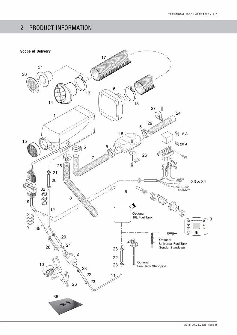
2 Product inFormation
scope of Delivery
29.2100.02.2326 issue h
8 | t e c h n i c a l d o c u m e n t a t i o n
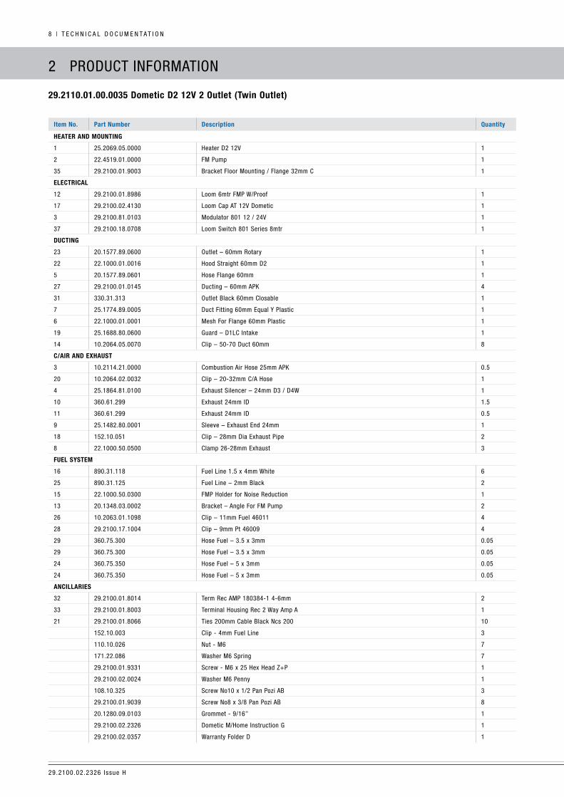
2 Product inFormation
29.2110.01.00.0035 Dometic D2 12V 2 outlet (twin outlet)
item no. part number Description Quantity
heater anD mountinG
1 25.2069.05.0000 heater d2 12v 1
2 22.4519.01.0000 Fm Pump 1
35 29.2100.01.9003 Bracket Floor mounting / Flange 32mm c 1
electrical
12 29.2100.01.8986 loom 6mtr FmP W/Proof 1
17 29.2100.02.4130 loom cap at 12v dometic 1
3 29.2100.81.0103 modulator 801 12 / 24v 1
37 29.2100.18.0708 loom Switch 801 Series 8mtr 1
DuctinG
23 20.1577.89.0600 outlet – 60mm rotary 1
22 22.1000.01.0016 hood Straight 60mm d2 1
5 20.1577.89.0601 hose Flange 60mm 1
27 29.2100.01.0145 ducting – 60mm aPK 4
31 330.31.313 outlet Black 60mm closable 1
7 25.1774.89.0005 duct Fitting 60mm equal Y Plastic 1
6 22.1000.01.0001 mesh For Flange 60mm Plastic 1
19 25.1688.80.0600 Guard – d1lc intake 1
14 10.2064.05.0070 clip – 50-70 duct 60mm 8
c/air anD eXhaust
3 10.2114.21.0000 combustion air hose 25mm aPK 0.5
20 10.2064.02.0032 clip – 20-32mm c/a hose 1
4 25.1864.81.0100 exhaust Silencer – 24mm d3 / d4W 1
10 360.61.299 exhaust 24mm id 1.5
11 360.61.299 exhaust 24mm id 0.5
9 25.1482.80.0001 Sleeve – exhaust end 24mm 1
18 152.10.051 clip – 28mm dia exhaust Pipe 2
8 22.1000.50.0500 clamp 26-28mm exhaust 3
fuel sYstem
16 890.31.118 Fuel line 1.5 x 4mm White 6
25 890.31.125 Fuel line – 2mm Black 2
15 22.1000.50.0300 FmP holder for noise reduction 1
13 20.1348.03.0002 Bracket – angle For Fm Pump 2
26 10.2063.01.1098 clip – 11mm Fuel 46011 4
28 29.2100.17.1004 clip – 9mm Pt 46009 4
29 360.75.300 hose Fuel – 3.5 x 3mm 0.05
29 360.75.300 hose Fuel – 3.5 x 3mm 0.05
24 360.75.350 hose Fuel – 5 x 3mm 0.05
24 360.75.350 hose Fuel – 5 x 3mm 0.05
ancillaries
32 29.2100.01.8014 term rec amP 180384-1 4-6mm 2
33 29.2100.01.8003 terminal housing rec 2 Way amp a 1
21 29.2100.01.8066 ties 200mm cable Black ncs 200 10
152.10.003 clip - 4mm Fuel line 3
110.10.026 nut - m6 7
171.22.086 Washer m6 Spring 7
29.2100.01.9331 Screw - m6 x 25 hex head Z+P 1
29.2100.02.0024 Washer m6 Penny 1
108.10.325 Screw no10 x 1/2 Pan Pozi aB 3
29.2100.01.9039 Screw no8 x 3/8 Pan Pozi aB 8
20.1280.09.0103 Grommet - 9/16’’ 1
29.2100.02.2326 dometic m/home instruction G 1
29.2100.02.0357 Warranty Folder d 1

29.2100.02.2326 issue h
t e c h n i c a l d o c u m e n t a t i o n | 9
2 Product inFormation
scope of Delivery
11
32 & 33
37
29
30
2820
Eberspächer
36
13
15
26
26
26
26
12
35
OptionalFuel Tank Standpipe
Optional10L Fuel Tank
31
OptionalUniversal Fuel TankSender Standpipe
35

29.2100.02.2326 issue h
1 0 | t e c h n i c a l d o c u m e n t a t i o n
2 Product inFormation
Provided no limit values are given, the technical data listed is
subject to the tolerances usually applicable to heaters of ±10% for
normal voltage, ambient temperature 20°c and reference altitude
esslingen, Germany.
caution!
safety instructions for technical data.
Failure to comply with the technical data can result in malfunctions.
technical Data for D2 anD D4
heater airtronic
heating medium air
control of the heat Flow Power large medium Small off
heat Flow (Watt)d2 2,200 1,800 1,200 850 –
d4 4,000 3,000 2,000 900 –
heater air Flow rated2 with 60mm hood 105 90 60 40 13
d4 with 90mm hood 185 150 110 60 24
Fuel consumption (l/h)d2 0.28 0.23 0.15 0.10 –
d4 0.51 0.38 0.25 0.11 –
electrical Power consumption (Watt)
– 12 and 24 volt
d2 in operation 34 22 12 8 5
d4 in operation 40 24 13 7 5
at Start ≤100
rated voltage 12 volt or 24 volt
operating range:
lower voltage limit: an undervoltage protection in the controller switches the
heater off when the voltage limit is reached.
approx. 10.5 volt resp. 21 volt
undervoltage Protection trigger time: 20 Seconds
operating range:
upper voltage limit: an overvoltage protection in the controller switches the
heater off when the voltage limit is reached.
approx. 16 volt resp. 32 volt
overvoltage Protection trigger time: 20 Seconds
Fuel
“Fuel Quality” and ‘Fuel at low temperatures”, see page ??.commercially available diesel Fuel (din en 590)
tolerable ambient temperature operation not running
heater -40°c to +70°c -40°c to +85°c
dosing Pump -40°c to +50°c -40°c to +125°c
maximum air intake temperature +40°c
interference Suppression interference Suppression class 5 to din en 55 025
Weight d2 approx. 2.7kg – d4 approx. 4.5kg
ventilation mode Possible
*
main Dimensions

29.2100.02.2326 issue h
t e c h n i c a l d o c u m e n t a t i o n | 1 1
3 inStallation
installation anD location
the heater is to be located within the caravan or r.v, maybe under
a bunk space or in cupboard or wardrobe.
the warm intake air is to be routed from within the vehicle either
by venting the area the heater is located or via 60mm ducting to
the intake.
the warm hot air outlet is routed via 60mm ducting to a
permanently open outlet. a secondary closable outlet maybe fitted.
the exhaust, combustion air and fuel connection must be external
and routed to a clean fresh air environment under the vehicle and
routed away from the annex.
the electrical circuit diagram must be followed, however the kit
contains a plug and play wiring loom.
only a suitable size cable is required to be routed from the 12 volt
battery source (6mm auto cable preferred).
the controller should be located approximately 1,500mm above the
floor in a position away from external heat sources, such as direct
sunlight, heat from the refrigerator unit and away from cold drafts
such as vents to the outside.
the regulations and safety instructions to be observed for this
chapter are on pages 4 – 7 of the technical Book.
possible installation positions
the heater is preferably installed in the normal position as shown
in the drawing.
depending on the installation conditions, the heater can be tilted
by max. 30° (flow direction to the bottom) or turned by max. 90°
around its own longitudinal axis (exhaust connection horizontal,
glow plug points upwards).
1 – Heater Air Intake Opening (Fan Wheel).
2 – Position of the Glow Plug.
3 – Direction of Flow.
normal position horizontal (exhaust connection Downwards) with tolerable swivel range
29.2100.02.2326 issue h
1 2 | t e c h n i c a l d o c u m e n t a t i o n
nameplate
the nameplate is fastened to the front of the heater. the second
nameplate (duplicate) is included in the scope of supply of the
heater.
if required, the duplicate nameplate can be adhered in a clearly
visible position on the heater or near to the heater.
1 – Original Nameplate.
2 – 2nd Nameplate (Duplicate).
3 inStallation
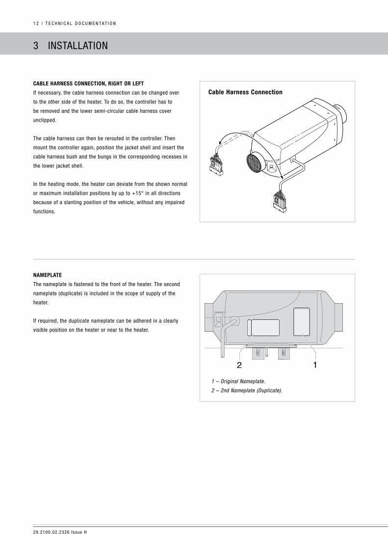
cable harness connection, riGht or left
if necessary, the cable harness connection can be changed over
to the other side of the heater. to do so, the controller has to
be removed and the lower semi-circular cable harness cover
unclipped.
the cable harness can then be rerouted in the controller. then
mount the controller again, position the jacket shell and insert the
cable harness bush and the bungs in the corresponding recesses in
the lower jacket shell.
in the heating mode, the heater can deviate from the shown normal
or maximum installation positions by up to +15° in all directions
because of a slanting position of the vehicle, without any impaired
functions.
cable harness connection

29.2100.02.2326 issue h
t e c h n i c a l d o c u m e n t a t i o n | 1 3
mountinG anD fasteninG
use the supplied floor plate 29.2100.01.9003. this requires a
125mm diameter hole to allow the flange to seal through the floor.
it is pre-drilled with the necessary breakthroughs.
1 – There must be sufficient clearance between the heater and
the vehicle floor – also check that the fan wheel runs freely.
2 – The mounting surface must be flat and smooth.
3 – The flange seal must be mounted.
4 – Spring Washer.
5 – Hexagon Nut M6 (torque 5 +1Nm).
fastening the unit on the Vehicle floor
pre-fit the flange to the heater before placing the heater in position

29.2100.02.2326 issue h
1 4 | t e c h n i c a l d o c u m e n t a t i o n
3 inStallation
heater DuctinG
DanGer!
risk of burning and injuries.
the hoses of the heater air system and the hot air outlet are
to be routed and fastened in such a way that they pose no
temperature risk to people, animals or materials sensitive to
temperature from radiation / contact or blowing directly. if
necessary, a cover is to be fitted to the heater air system or
hot air outlet.
the outflow hood must be fitted on the hot air outflow side.
a safety grill must be fitted to the heater air intake side and
outflow side to prevent any injuries from the heater air fan or
burns from the heat exchanger.
high temperatures occur in the heater ducting system during
and after the heater have been working.
this is why it is important to avoid working in the vicinity of the
heater air system while the heater is working. in such cases, switch
the heater off beforehand and wait until all parts have cooled down
completely.
if necessary, wear safety gloves.
caution!
the heater air intake openings must be arranged in such a way
that under normal circumstances, it is not possible for exhaust
from a vehicle engine or heater to be drawn into the system,
or for the heating air to be contaminated with dust, salt spray,
etc.
For circulating air, position the circulating air intake in such
a way that the outflowing hot air cannot be directly drawn in
again.
in the event of possible overheating, it is possible for local hot
air temperatures of up to max. 150°c or surface temperatures
of up to max. 90°c to occur, immediately before the defect
shutdown.
therefore only temperature-resistant hot air ducting approved
by us must be used for the heater air system.
When checking the functions, the mean outflow temperature
measured after the heater has been running about 10 minutes
at approx. 30cm from the outlet should not exceed 110°c (at
an intake temperature of approx. 20°c).
if there is a risk of the driver and passengers touching the
heater when the vehicle is being driven normally, a contact
protection device must be fitted.
1 – Intake Guard. 2 – Outlet Hood. 3 – Duct Clip. 4 – Ducting.
5 – Outlet. 6 – 60mm Flange. 7 – Mesh.
heater air Duct system (example)

29.2100.02.2326 issue h
t e c h n i c a l d o c u m e n t a t i o n | 1 5
3 inStallation
eXhaust sYstem
mountinG the eXhaust sYstem
the installation kits include stainless steel flexible exhaust pipes,
inner Ø 24mm, 1,500mm long and 500mm long and an exhaust
silencer. the flexible exhaust pipe can be shortened to 20cm
or lengthened to a maximum 2m, depending on the installation
conditions.
Fasten the exhaust silencer to a suitable position under the
caravan / motorhome.
route the flexible exhaust pipe from the heater to the exhaust
silencer and fasten with pipe clips. use a pipe clip to fix a short
exhaust pipe end (with end sleeve) to the exhaust silencer. route to
the offside, not under an opening window or awning area.
do not route the exhaust gases to the annex side of a caravan or
motorhome.
caution!
safety instructions.
the whole exhaust system gets very hot during and immediately
after the heater has been working.
this is the reason why the exhaust system must be installed
according to these instructions.
the exhaust outlet must end in the open air.
the exhaust pipe must not protrude beyond the lateral limits of
the vehicle.
install the exhaust pipe sloping slightly downwards. if
necessary, make a drain hole approx. Ø 5mm at the lowest
point to drain off condensation.
important functional parts of the vehicle must not be impaired
(keep sufficient clearance).
mount the exhaust pipe with sufficient clearance to heat-
sensitive parts. Pay particular attention to fuel pipes (plastic or
metal), electrical cables and brake hoses etc.
exhaust pipes must be fastened safely (recommended spacing
of 50cm) to avoid damage from vibrations.
route the exhaust system so that the emitted fumes are not
drawn in with the combustion air.
the mouth of the exhaust pipe must not get clogged by dirt
and snow.
the mouth of the exhaust pipe must not point in the direction
of travel.
always fasten the exhaust silencer to the vehicle.
caution!
risk of injuries and burns.
every type of combustion produces high temperatures and toxic
exhaust fumes. the exhaust system must be installed according to
these instructions.
do not perform any work on the exhaust system while the
heater is working.
Before working on the exhaust system, first switch the heater
off and wait until all parts have cooled down completely, wear
safety gloves if necessary.
do not inhale exhaust fumes.
comply with the regulations and safety instructions for this
chapter on page 4 – 7 (technical Book).
When the silencer is fitted, the exhaust end pipe must be
shorter than the flexible exhaust pipe between the heater and
the exhaust silencer.
Small arrows indicating the direction of flow have been cast
into the fittings to differentiate between the combustion air (8)
and the exhaust fittings (9) at the heater, see figure below.
29.2100.02.2326 issue h
1 6 | t e c h n i c a l d o c u m e n t a t i o n
3 inStallation
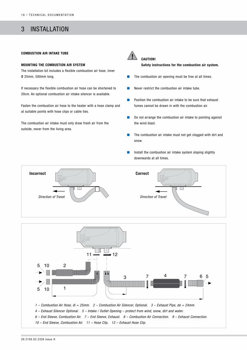
combustion air intake tube
mountinG the combustion air sYstem
the installation kit includes a flexible combustion air hose, inner
Ø 25mm, 500mm long.
if necessary the flexible combustion air hose can be shortened to
20cm. an optional combustion air intake silencer is available.
Fasten the combustion air hose to the heater with a hose clamp and
at suitable points with hose clips or cable ties.
the combustion air intake must only draw fresh air from the
outside, never from the living area.
caution!
safety instructions for the combustion air system.
the combustion air opening must be free at all times.
never restrict the combustion air intake tube.
Position the combustion air intake to be sure that exhaust
fumes cannot be drawn in with the combustion air.
do not arrange the combustion air intake to pointing against
the wind blast.
the combustion air intake must not get clogged with dirt and
snow.
install the combustion air intake system sloping slightly
downwards at all times.
1 – Combustion Air Hose, di = 25mm. 2 – Combustion Air Silencer, Optional. 3 – Exhaust Pipe, de = 24mm.
4 – Exhaust Silencer Optional. 5 – Intake / Outlet Opening – protect from wind, snow, dirt and water.
6 – End Sleeve, Combustion Air. 7 – End Sleeve, Exhaust. 8 – Combustion Air Connection. 9 – Exhaust Connection.
10 – End Sleeve, Combustion Air. 11 – Hose Clip. 12 – Exhaust Hose Clip.
incorrect correct
Direction of Travel Direction of Travel

29.2100.02.2326 issue h
t e c h n i c a l d o c u m e n t a t i o n | 1 7
3 inStallation
fuel supplY
mountinG the DosinG pump anD routinG the fuel pipes
the following safety instructions must be observed when mounting
the dosing pump, routing the fuel pipes.
deviations from the instructions stated here are not allowed.
Failure to comply can result in malfunctions.
DanGer!
risk of injury.
caution when handling fuel:
Switch off the towing vehicle engine, generator and heater
before refuelling and before working on the fuel supply.
no naked lights when handling fuel.
do not smoke.
do not inhale fuel vapours.
avoid any contact with the skin.
caution!
safety instructions for routing the fuel pipes.
only use a sharp knife to cut off fuel hoses and pipes.
interfaces must not be crushed and must be free of burrs.
the fuel pipe from the dosing pump to the heater should be
routed at a continuous rise.
Fuel pipes must be fastened safely to avoid any damage and /
or noise production from vibrations (recommended spacing of
approx. 50cm).
Fuel pipes must be protected from any mechanical damage.
Parts carrying fuel must be protected from interfering heat.
never route or fasten the fuel pipes to the heater or any
other exhaust system. at crossings, always ensure adequate
heat clearance; if necessary attach heat deflection plates or
protective hose.
dripping or evaporating fuel must never be allowed to collect
on hot parts or ignite on electric systems.
When connecting fuel pipes with a fuel hose, always mount the
fuel pipes in a butt joint to prevent any bubbles from forming.
1 – Correct Connection.
2 – Incorrect Connection – bubble formation.
the fuel lines are colour coded.
black or blue fuel line is used between the tank and the dosing
pump.
White fuel line is used between the dosing pump and the heater.
the fuel lines supplied are a special size with a very small internal
hole. never use any other type of fuel line.
29.2100.02.2326 issue h
1 8 | t e c h n i c a l d o c u m e n t a t i o n
3 inStallation
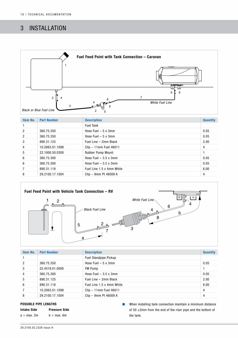
item no. part number Description Quantity
1 Fuel tank
2 360.75.350 hose Fuel – 5 x 3mm 0.05
2 360.75.350 hose Fuel – 5 x 3mm 0.05
3 890.31.125 Fuel line – 2mm Black 2.00
4 10.2063.01.1098 clip – 11mm Fuel 46011 4
5 22.1000.50.0300 rubber Pump mount 1
6 360.75.300 hose Fuel – 3.5 x 3mm 0.05
6 360.75.300 hose Fuel – 3.5 x 3mm 0.05
7 890.31.118 Fuel line 1.5 x 4mm White 6.00
8 29.2100.17.1004 clip – 9mm Pt 46009 a 4
fuel feed point with Vehicle tank connection – rV
item no. part number Description Quantity
1 Fuel Standpipe Pickup
2 360.75.350 hose Fuel – 5 x 3mm 0.05
3 22.4519.01.0000 Fm Pump 1
4 360.75.300 hose Fuel – 3.5 x 3mm 0.05
5 890.31.125 Fuel line – 2mm Black 2.00
6 890.31.118 Fuel line 1.5 x 4mm White 6.00
7 10.2063.01.1098 clip – 11mm Fuel 46011 4
8 29.2100.17.1004 clip – 9mm Pt 46009 a 4
possible pipe lenGths
intake side pressure side
a = max. 2m b = max. 6m
When installing tank connection maintain a minimum distance
of 50 ±2mm from the end of the riser pipe and the bottom of
the tank.
Black Fuel Line
White Fuel Line
Black or Blue Fuel Line
White Fuel Line
fuel feed point with tank connection – caravan
29.2100.02.2326 issue h
t e c h n i c a l d o c u m e n t a t i o n | 1 9
3 inStallation
caution!
safety instructions for the fuel supply.
the fuel must not be conveyed by gravity or overpressure in
the fuel tank.
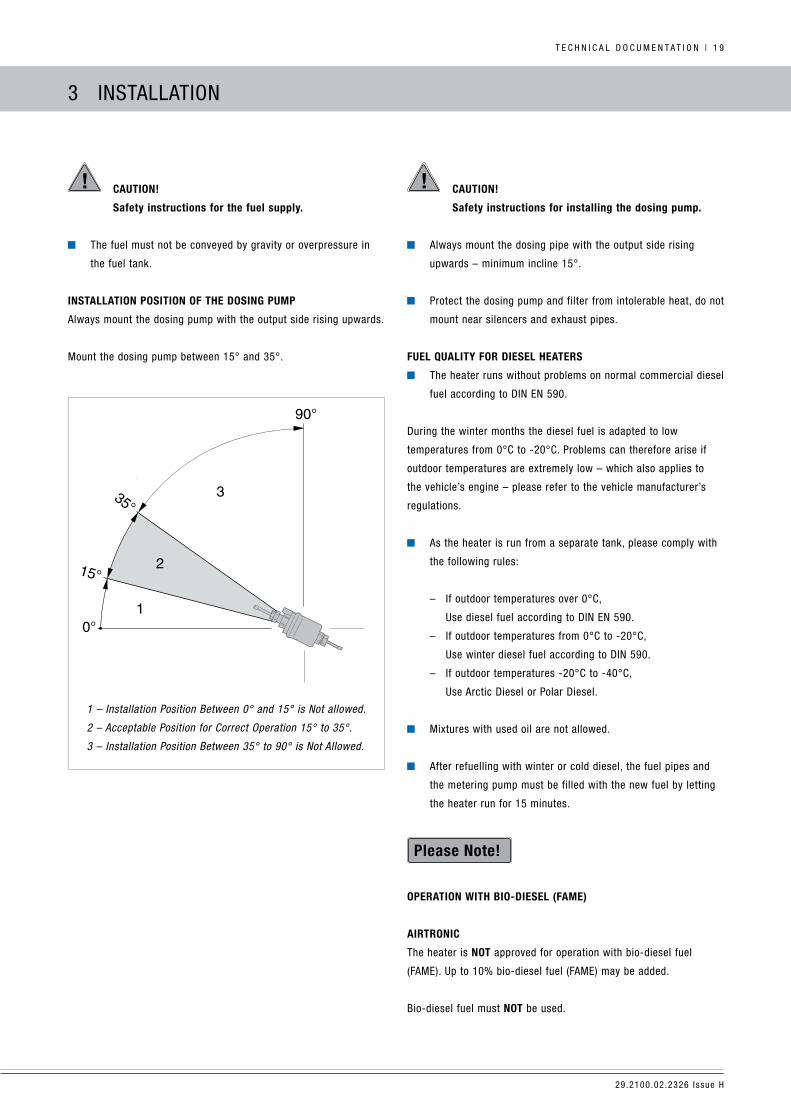
installation position of the DosinG pump
always mount the dosing pump with the output side rising upwards.
mount the dosing pump between 15° and 35°.
caution!
safety instructions for installing the dosing pump.
always mount the dosing pipe with the output side rising
upwards – minimum incline 15°.
Protect the dosing pump and filter from intolerable heat, do not
mount near silencers and exhaust pipes.
fuel QualitY for Diesel heaters
the heater runs without problems on normal commercial diesel
fuel according to din en 590.
during the winter months the diesel fuel is adapted to low
temperatures from 0°c to -20°c. Problems can therefore arise if
outdoor temperatures are extremely low – which also applies to
the vehicle’s engine – please refer to the vehicle manufacturer’s
regulations.
as the heater is run from a separate tank, please comply with
the following rules:
– if outdoor temperatures over 0°c,
use diesel fuel according to din en 590.
– if outdoor temperatures from 0°c to -20°c,
use winter diesel fuel according to din 590.
– if outdoor temperatures -20°c to -40°c,
use arctic diesel or Polar diesel.
mixtures with used oil are not allowed.
after refuelling with winter or cold diesel, the fuel pipes and
the metering pump must be filled with the new fuel by letting
the heater run for 15 minutes.
operation With bio-Diesel (fame)
airtronic
the heater is not approved for operation with bio-diesel fuel
(Fame). up to 10% bio-diesel fuel (Fame) may be added.
Bio-diesel fuel must not be used.
1 – Installation Position Between 0° and 15° is Not allowed.
2 – Acceptable Position for Correct Operation 15° to 35°.
3 – Installation Position Between 35° to 90° is Not Allowed.

29.2100.02.2326 issue h
2 0 | t e c h n i c a l d o c u m e n t a t i o n
4 oPeration and Function
operatinG instructions
the heater is operated by a control thermostat. detailed operating
instructions are enclosed with the control unit. the workshop
/ garage installing the heater will issue you with the operating
instructions.
important instructions for operation
safetY checks before the start
after a lengthy period of non-use (summer months) check that all
parts fit securely (tighten screws where necessary). change to fresh
diesel fuel when separate fuel tank is used.
check the fuel system visually for any leaks.
heatinG at hiGh altituDes
When using the heater at high altitudes, please note:
heating at altitudes up to 1,500m:
– unlimited heating possible.
heating at altitudes over 1,500m – 3,000m:
– heating is possible for short periods at this altitude
(e.g. driving over a mountain pass or taking a break in a
journey).
– during longer stays (e.g. winter camping), the fuel supply
must be adjusted to the altitude. this can be done by
installing an air pressure sensor. the air pressure sensor is
included in the altitude kit – order no. 22.1000.33.22.00.
heaters suitable for high altitudes are labelled with “h-Kit” on the
side nameplate.
initial commissioninG
the following points are to be checked by the company installing
the heater during initial commissioning:
after installation of the heater, fuel supply system must be
vented carefully.
during the trial run of the heater, check fuel connections for
leaks and firm fitting.
if the heater shows a fault during operation, find and eliminate
the cause of the fault.
during the initial start-up of the heater, odours can be produced
for a short time. this is fully normal during the first few minutes of
operation and does not indicate a malfunction in the heater.
Description of functions
sWitchinG on
When the heater is switched on, the control lamp in the control
element lights up.
the glow pin is switched on and the fan starts at low speed.
if there is still too much residual heat in the heat exchanger from
when the heater was last used, firstly only the fan starts up (cold
blowing).
once the residual heat has been cleared, the heater starts.
startinG airtronic
after approx. 65 seconds the fuel supply starts and the fuel / air
mixture in the combustion chamber ignites.
once the combined sensor (flame sensor) has detected the flame,
the glow pin is switched off after 60 seconds. the heater is now in
standard operation.
temperature selection With the control element
the control can be used to preselect an interior temperature.
the resulting temperature can be within the range of +5°c to
+30°c and depends on the selected heater, on the size of the space
to be heated and on the prevailing outdoor temperature.
the setting to be selected at the control is an empirical value.

29.2100.02.2326 issue h
t e c h n i c a l d o c u m e n t a t i o n | 2 1
4 oPeration and Function
control in the heatinG moDe
during the heating mode the temperature of the air being drawn
into the heater is constantly measured.
there are 4 control stages so that the outflow of heat produced by
the heater can be adjusted finely to the heating requirements. Fan
speed and fuel quantity correspond to the particular control stage.
if the set temperature is still exceeded in the smallest control
stage, the heater goes to the “oFF” stage with the fan running on
for approx. 4 minutes to cool off.
then the fan continues at minimum speed (circulation mode) or is
switched off (fresh air mode) until the heater is started again.
When the air temperature cools the heater will start again
automatically.
VentilatinG moDe
Select ventilation mode. the fan will run only some controls (no
heating).
sWitchinG off
When the heater is switched off, the control lamp goes off and the
fuel supply is switched off.
the fan runs on for approx. 4 minutes to cool down.
While the fan is running on, the glow pin is switched on for approx.
40 seconds to clean.
special case:
if no fuel has been supplied or if the heater is in the “oFF” stage
until it is switched off, the heater is stopped without any after
running.
never terminate the 12 volt supply to the heater while it is running,
always use the off button on the control.
control anD safetY DeVices
if the heater does not ignite within 90 seconds after starting
the fuel pump, the start is repeated. if the heater still does not
ignite after another 90 seconds of pumping fuel, the heater is
switched off, e.g. the fuel supply is off and the fan runs on for
approx. 4 minutes. (Fault code 52).
if the flame goes off by itself during operation, the heater is
restarted. if the heater does not ignite within 90 seconds after
the fuel pump has started, or ignites and goes off again within
15 minutes, the heater is switched off, e.g. the fuel supply is
off and the fan runs on for approx. 4 minutes.
this status can be remedied by briefly switching off and on
again. (Fault code 53-56).
do not repeat the switching off / on routine more than twice.
in the case of overheating, the combined sensor (flame sensor
/ overheating sensor) triggers, the fuel supply is interrupted
and the heater switched off. once the cause of the overheating
has been eliminated, the heater can be re-started by switching
off and on again (Fault code 12).
if the lower or upper voltage limit is reached, the heater is
switched off after 20 seconds (Fault code 10 or 11).
the heater does not start up when the glow pin is defective or
when the electric lead to the dosing pump is interrupted (Fault
code 20 or 48).
if the combined sensor (flame sensor / overheating sensor) is
defect or the electric lead interrupted, the heater starts up and
is then switched off again during the start phase (Fault code
61-61).
the speed of the fan motor is monitored continuously. if the
fan motor does not start up or if the speed deviates by more
than 10%, the heater is switched off after 30 seconds (Fault
code 31-33).
When the heater is switched off, the glow pin is switched on
for 40 seconds (after-glowing) while the fan runs on to clean
off any combustion residues.
do not switch the heater off and on again more than twice.
29.2100.02.2326 issue h
2 2 | t e c h n i c a l d o c u m e n t a t i o n
4 oPeration and Function
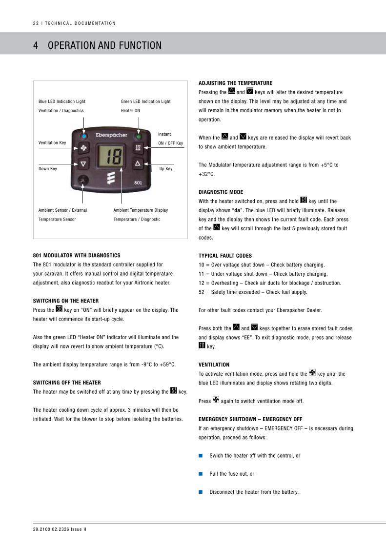
801 moDulator With DiaGnostics
the 801 modulator is the standard controller supplied for
your caravan. it offers manual control and digital temperature
adjustment, also diagnostic readout for your airtronic heater.
sWitchinG on the heater
Press the key on “on” will briefly appear on the display. the
heater will commence its start-up cycle.
also the green led “heater on” indicator will illuminate and the
display will now revert to show ambient temperature (°c).
the ambient display temperature range is from -9°c to +59°c.
sWitchinG off the heater
the heater may be switched off at any time by pressing the key.
the heater cooling down cycle of approx. 3 minutes will then be
initiated. Wait for the blower to stop before isolating the batteries.
aDjustinG the temperature
Pressing the and keys will alter the desired temperature
shown on the display. this level may be adjusted at any time and
will remain in the modulator memory when the heater is not in
operation.
When the and keys are released the display will revert back
to show ambient temperature.
the modulator temperature adjustment range is from +5°c to
+32°c.
DiaGnostic moDe
With the heater switched on, press and hold key until the
display shows “da”. the blue led will briefly illuminate. release
key and the display then shows the current fault code. each press
of the key will scroll through the last 5 previously stored fault
codes.
tYpical fault coDes
10 = over voltage shut down – check battery charging.
11 = under voltage shut down – check battery charging.
12 = overheating – check air ducts for blockage / obstruction.
52 = Safety time exceeded – check fuel supply.
For other fault codes contact your eberspächer dealer.
Press both the and keys together to erase stored fault codes
and display shows “ee”. to exit diagnostic mode, press and release
key.
Ventilation
to activate ventilation mode, press and hold the key until the
blue led illuminates and display shows rotating two digits.
Press again to switch ventilation mode off.
emerGencY shutDoWn – emerGencY off
if an emergency shutdown – emerGencY oFF – is necessary during
operation, proceed as follows:
Swich the heater off with the control, or
Pull the fuse out, or
disconnect the heater from the battery.
Blue led indication light
ventilation / diagnostics
Green led indication light
heater on
ventilation Key
down Key
ambient Sensor / external
temperature Sensor
ambient temperature display
temperature / diagnostic
up Key
instant
on / oFF Key

29.2100.02.2326 issue h
t e c h n i c a l d o c u m e n t a t i o n | 2 3
1. instant heat on/oFF key.
2. adjustment up key.
3. disengaged pre-set symbol.
4. ventilation symbol.
5. temperature ramp.
6. current time, Preset time,
heating time, run time
and diagnostics.
low heat high heat
7. day selected indicator
boxes.
8. clock symbol.
9. heater operation symbol.
10. Preset Programme
symbols.
11. adjustment down key.
12. Programme key.
13. Set / Programme key.
8
9
10
11
12
13
7
6
5
4
3
2
1
701 timer / moDulator With DiaGnostics
Your timer / modulator offers manual and programmable control
along with temperature adjustment of your heater. When the heater
is switched on by the timer / modulator in a programmed mode it
will run for 1 hour or for the duration time that you have selected
e.g heater on at 0700, duration time of 1 hour, which means heater
will be switched off automatically at 0800.
clock settinGs
Press and hold key until the symbol begins to flash. use
the and keys to set correct time. Press and release the
key and the day box will begin to flash. use the and keys
to set the correct day. Press and release the key again to reset
the clock to the start of the minute displayed. this may be used to
coincide with a known time signal.
these adjustments are not possible when the heater is in operation.
to set the heater’s programmable switch on timer, see “Setting
Program times”.
sWitchinG on the heater (manuallY)
Press the key and the symbol will appear on the display. the
heater will commence its startup cycle. the display will change to
show a default of one hour heating countdown time. this can be
extended in increments of 10 minutes, 30 minutes, 1 hour, 1 hour
30 minutes, 2 hours up to eight hours or to continuous running
operation (shown as c-: -- on display) by repeatedly pressing
the key while the heater is in operation. current time will be
displayed every 5 seconds.
sWitchinG off the heater (manuallY)
the heater may be switched off at any time by pressing the key.
the cooling down cycle will then be initiated.
aDjustinG the temperature
Pressing the and keys will alter the 20 segment temperature
ramp shown on the display. this level may be adjusted at any
time and will remain in the timer memory when the heater is not in
operation.
DiaGnostic reaDout
With the heater switched on, press and hold key until the
display shows “data”. release key and display then shows “aF--”
and alternatively displays the current fault code. each press of the
key will scroll through the last 5 previously stored fault codes.
typical fault codes:
10 = over voltage – check battery charging system.
11 = under voltage – check battery voltage.
12 = overheating – check air ducts for obstruction.
52 = Safety time exceeded – check fuel supply.
For other codes consult your local dealer.
Press and keys together to erase stored faults and display
shows “eeee”.
to exit diagnostic mode, press and release the key. if stored
faults cannot be erased consult your local dealer.
heater run time
Press and hold the key until the display shows the heater run
time in hours.
4 oPeration and Function
29.2100.02.2326 issue h
2 4 | t e c h n i c a l d o c u m e n t a t i o n
settinG proGramme times
Press the key and the P1 symbol will begin to flash. Pressing
the key will alternate the display between a preset time display
and “oFF”. With P1 flashing in the time display mode the desired
programme time can be set using the and keys.
once the desired time has been selected and if no keys are
depressed for 8 seconds the display will revert to the clock mode.
during this 8 second period pressing the key will select P2
which can be used to select another programme time or be set to
“oFF” if not required.
a further pressing of the key will select the P3 symbol which
can be set or turned off in the same manner as above.
settinG proGramme DaYs
having set programme times P1, P2 or P3 or all three, press the
key, all the ‘P’ symbols that have been selected will start flashing
and a box will appear around one of the days. Press the key to
select “on” if you require the selected day to be programmed, or
“oFF” if you do not wish it to be selected.
to move onto the following day press the key once again and
select “on” or “oFF” as before. repeat this procedure for all seven
days. to store these settings in the timer / modulator memory, wait
for 8 seconds and the display will revert to the clock mode.
settinG proGramme Duration
to set the desired heater duration, press and hold the key and
whilst holding repeatedly press the key to select the desired
time in increments of 10 minutes, 30 minutes, 1 hour,
1 hour 30 minutes, 2 hours up until 8 hours.
continuous operation is not selectable in this programme mode.
once stored the preset duration time cannot be adjusted during
heater “on” operation.
sWitchinG on the heater (proGrammeD)
to activate your selected program settings, press the key to
show the P1, P2, P3 (to determine when the heater will switch on)
or symbol P to turn off all settings.
if all presets and days have been selected to “oFF” pressing the
key will have no effect.
When the heater has been switched on manually, it is possible to
view which of the programmed times have been set and whether
or not they have been activated. Press the key to view and if
any programmed time has been activated, its corresponding P will
flash. if no programmed times have been activated then P flashes.
Press the key to activate or de-activate the programmed times
as required. Wait 8 seconds and the display will revert to manual
operation countdown.
Ventilation
to activate ventilation mode, repeatedly press key until only
one segment shows in the ramp. Press and hold the key until
shows and display changes to 1 hour countdown. to stop
ventilation, press key to return to normal display time.
the ventilation countdown time of 1 hour is not adjustable.
4 oPeration and Function

29.2100.02.2326 issue h
t e c h n i c a l d o c u m e n t a t i o n | 2 5
5 electrical SYStem
heater WirinG
caution!
safety instructions for wiring the heater.
the heater is to be connected up electrically according to the emc
directives.
emc can be affected if the heater is not connected up correctly. For
this reason, comply with the following instructions:
ensure that the insulation of electrical cables is not damaged.
avoid: chafing, kinking, and jamming or exposure to heat.
electrical connections and ground connections must be free of
corrosion and firmly connected.
comply with the following when wiring the heater and the control
element:
electrical leads, switchgear and controllers must be arranged
in the vehicle so that they can function perfectly under normal
operating conditions (e.g. heat exposure, moisture etc.).
12 Volt Dc connection
the heater must be connected to the 12 volt supply battery using
suitable dc cable. voltage drop must not exceed 0.5v for 12 volt
connection.
minimum cable size for lengths up to 2 metres between the heater
and the battery is 4mm2. minimum cable size for lengths up to
8 metres is 6mm2.
the 12 volt dc connection must be a permanent dedicated
connection. turning the 12 volt dc supply off while the heater is
running may damage the heater.
the heater must always be shut down using the control panel, this
allows the heater to turn off then pass through a cool-down stage.
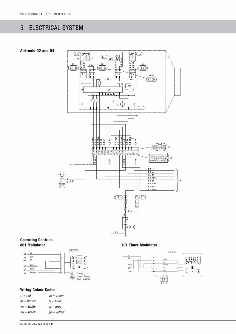
parts list for the circuit Diagrams airtronic
1.1 – Blower Motor.
1.2 – Glow Pin.
1.5 – Overheating and Flame Sensor.
2.1 – ICU Controller.
2.2 – Fuel Metering Pump.
2.7 – Main fuse 12 volt = 20 A.
2.7.1 – Fuse, actuation 5 A.
5.1 – Battery.
a) – Connection of the control unit and external sensor according to
the circuit diagram “operating controls”.
rt – red – Power Supply, Plus – Terminal 30.
ge – yellow – Switch-on Signal – S+.
gr – grey – Actual Temperature.
br – brown – Power Supply, Minus – Terminal 31.
blws – blue/white – Diagnosis.
grrt – grey/red – Nominal Temperature.
brws – brown/white – Reference Signal Sensor.
29.2100.02.2326 issue h
2 6 | t e c h n i c a l d o c u m e n t a t i o n
5 electrical SYStem
airtronic D2 and D4
801 modulator 701 timer modulatoroperating controls
Wiring colour codesrt – red gn – green
br – brown bl – blue
ws – white gr – grey
sw – black ge – yellow
3.2.10rtge
gr/rtbl/ws
br/ws
Eberspächer
1
2
3
4
5
6
a1a2
a7a6
1 23 45 6
6 wayJunior PowerTab Housing
a8
gra3
4 5 6
1 2 3
rtge
gr/rt
br/ws
1
2
3
4
5
6
3.2.9
bl/ws
gr/rt
gertbl/wsbr

29.2100.02.2326 issue h
t e c h n i c a l d o c u m e n t a t i o n | 2 7
6 trouBleShootinG / maintenance / Service
in case of faults, please check the folloWinG points
if the heater does not start after being switched on:
– Switch the heater off and on again.
if the heater still does not start, check whether:
– there is fuel in the tank?
– the fuses are oK?
– the electrical cables, connections etc. are oK?
– anything is clogging the combustion air supply or exhaust
system?
– call up the diagnostics using the operating device to
identify the fault.
troubleshootinG
if the heater remains faulty even after these points have been
checked, or another malfunction occurs in your heater, please
contact:
dometic australia Pty tel: 039239 1000 for your local eberspacher
dealer:
Please note that warranty claims can be become void if the heater
is tampered with by unauthorised persons or modified in any way.
maintenance instructions
Switch the heater on once a month for about 10 minutes, even
outside the winter period.
Before the winter period starts, the heater should undergo a
trial run.
if persistent extreme smoke develops, unusual burning noises or
a clear fuel smell can be perceived or if electric / electronic parts
heat up, the heater must be switched off and put out of service by
removing the fuse.
in this case, the heater should not be started up again until it
has been checked by qualified staff that has been trained on
eberspacher heaters.
check the openings of the combustion air supply and exhaust
system after longer standstill periods, clean if necessary.
Be aware of vermin building nest or occupying the air intake or
exhaust.
serVice
if you have any technical queries or problems with your heater
contact dometic australia Pty. tel: 039239 1000.
29.2100.02.2326 issue h
2 8 | t e c h n i c a l d o c u m e n t a t i o n
7 environment
certification
the high quality of eberspächer’s products is the key to our
success.
to guarantee this quality, we have organised all work processes in
the company along the lines of quality management (Qm).
even so, we still pursue a large number of activities for continuous
improvement of product quality in order to keep pace with the
similarly constantly growing requirements made by our customers.
all the steps necessary for quality assurance are stipulated in
international standards.
this quality is to be considered in a total sense.
it affects products, procedures and customer / supplier
relationships.
officially approved public experts assess the system and the
corresponding certification company awards a certificate.
eberspächer has already qualified for the following standards:
QualitY manaGement as per
Din en iso 9001:2000 anD iso/ts 16949:1999
enVironment manaGement sYstem as per
Din en iso 14001:1996
Disposal
Disposal of materials
old devices, defect components and packaging material can all be
separated and sorted into pure grade factions so that all parts can
be disposed of as required in an environment-friendly manner or
recycled where applicable.
electric motors, controllers and sensors (e.g. temperature sensors)
are deemed to be “electronic scrap”.
DismantlinG the heater
the heater is dismantled according to the repair stages in the
current troubleshooting / repair instructions.
packaGinG
the packaging of the heater can be kept in case it has to be sent
back.
eu Declaration of conformitY
With regard to the following products:
heater tYpe airtronic / airtronic m
We herewith confirm that it conforms with the prime safety
requirements stipulated in the directives of the eu council for
harmonisation of the legal regulations of the member states with
regard to electromagnetic compatibility (89 / 336 / eec).
this declaration applies to all heaters produced according to the
production drawings airtronic / airtronic m, which are an
integral part of this declaration.
the following standards / directives have been used to assess the
product with regard to electromagnetic compatibility:
en 50081 – 1 Basic form interference emission.
en 50082 – 1 Basic form interference resistance.
72 / 245 / eec – modification status 2005 / 83 / eu
interference suppression in motor vehicles.
29.2100.02.2326 issue h
t e c h n i c a l d o c u m e n t a t i o n | 2 9
8 liStS
list of abbreViations
ec tYpe approVal
Permit awarded by the Federal vehicle office for the production of a
heater for installation in motorised vehicles.
emc DirectiVe
electromagnetic compatibility.
je partner
J. eberspächer partner.
fame
Bio-diesel according to din v 14 214.
29.2100.02.2326 issue h
3 0 | t e c h n i c a l d o c u m e n t a t i o n
noteS
29.2100.02.2326 issue h
t e c h n i c a l d o c u m e n t a t i o n | 3 1
eberspächer (uk) ltd
climate house
Yeoman road, ringwood
hampshire Bh24 3Fa
tel: 01425 480151
Fax: 01425 480152
www.eberspacher.com
© eberspächer (uK) ltd. 2015
no part of this manual may be copied or reproduced in any form without the express permission of eberspächer (uK) ltd.
this publication was correct at the time of going to print however, eberspächer (uK) ltd have a policy of continuous improvement and reserve the
right to amend any specifications without prior notice.


