
www.milacron.com
DME Hot RunnER & ContRol SyStEM
S
DME Hot RunnER
& ContRol SyStEMS
DME Company USA29111 Stephenson HighwayMadison Heights, MI 48071 ☎ 800-626-6653 (toll-free) ☎ 248-398-6000 [email protected]
DME MexicoCircuito el Marques Norte, No. 55Parque Industrial El MarquésEl Marqués, Querétaro, CP 76246 ☎ 52 442 713 5666 [email protected]
DME Canada6510 Northwest DriveMississauga, ONT Canada L4V 1J6 ☎ 800-387-6600 (toll-free) ☎ 905-677-6370 [email protected]
© 2017 Milacron All rights reserved. Printed in the U.S.A.

DME Mold Technology Catalogs
DME: Your Complete Mold Technologies Provider
DM
E Mold Technology Catalogs | D
ME: Your Com
plete Mold Technologies Provider
Check Out All of the DME Mold Technology Catalogs And You’ll See Why We’re an Essential Resource to Thousands of Customers Worldwide!
Mold Bases & PlatesChoose from the world’s widest selection of mold bases from uniquely featured, off-the-shelf solutions to full-featured, custom-configured offerings. An array of standard and specially machined mold plate sizes gives you unlimited options.
Equipment and SuppliesFrom high-speed cutting tools and finishing and polishing systems to a vast array of maintenance, repair and operation-related products, the Equipment and Supplies Catalog is an invaluable resource for mold technology professionals.
MUD Quick-Change SystemsReduce downtime by as much as 75 percent with an innovative approach to fast production changeovers. Master Unit Die is the leader in quick-change systems and the MUD Catalog offers many systems that will maximize your production volume.
Mold ComponentsWith the largest selection of mold components available around the globe, the Mold Components Catalog has the products that will help you meet the unprecedented demands you face for speed, cost reduction and performance.
Industrial SuppliesFeaturing the best product offerings of Northern Supply, Nickerson and OHS, DME Industrial Supplies now has thousands more of the high-quality, economical MRO products you’ve come to expect from an industry leader.
Hot R
unne
r Sy
stem
s |
Tab
le o
f Con
tent
s
Hot Runner Services
The Hot One Technology .............................................24-42Meteor Hot Runner ......................................................43-50
Hot Runner Systems
Hot Sprue Bushings
DME Hot Runner Technology ......................................15-17Stellar Micromolding....................................................18-23
Thermal Gate Hot Runner Systems
Customer Commitment ........................................................4Terms and Conditions of Sale ............................................5Sales and Ordering Information ........................................6Hot Runner Warranty ..........................................................7Hot Runner Systems Overview ...................................... 8-9Custom Applications Engineered Hot Runner Systems Standard Global Manifold and Components .................10Hot Runner Selection Guide .............................................11Plastic Materials, Specifications/Bushing Selection ..12Hot Runner Quote Request Form .....................................13
Standard Pre-Engineered Hot Runner Systems
Obsolete System Replacement Parts
D-MAX............................................................................53-59Gate-Mate .....................................................................60-67Straight-Shot ................................................................68-78> High-Performance ....................................................69-70> S-Series ...........................71> E-Series ....................72-73> ER-Series .................74-75> T-Series ...........................76> TR-Series .........................77> Replacement Parts ........78Integrally Heated Sprue Bushings ...........................79-84
Moldflow ........................................................................86-87Moldflow Quote Request Form........................................88Hot Runner Service Center.........................................89-90
Gate-Mate......................................................................92-93Cool One.......................................................................94-101
Modular Components Deliver High Performance......102
Temperature Control SystemsSS TSP & TSP PlusTSP (Touch Screen Panel) ......................................105-108TSP Plus (Touch Screen Panel..............................109-110
Smart Series®
Typical System Configurations......................................115Single Zone Controllers...........................................116-1172-zone Controllers............................................................118Single & 2-zone Accessories.................................119-120Single Zone High Power Controller & Accessories...121Smart Series 15 AMP Mainframe Configurations...........................................................122-123Smart Series 30 AMP Mainframe Configurations..................................................................124Digital Current/Voltage Monitor.....................................125Floor Stand........................................................................126Step-Down Transformer Kits..........................................126Blank Panels, Fuses & Crimp Connectors...................126Mainframe Connector Wiring.................................127-129Mold Power & Thermocouple Cables..........................130Mold Power Input Connectors.......................................131Mold Thermocouple Connectors...................................132Mold Connector Pocket Layouts............................133-134Pre-wired Combination Terminal Mounting Boxes....135Terminal Mounting Boxes...............................................136SSM Modules............................................................137-138DSS Modules.............................................................139-140TSM Modules............................................................141-142TAS Temperature Alarm/System Modules...........143-144Replacement Parts...................................................145-147Input Wiring Diagram..............................................148-150Alternate Cable Configurations..............................151-154Stand Accessories..........................................................155
Valve Gate Controller Products & SolutionsSVG Pneumatic Control Systems...........................157-158SVG Hydraulic Control Systems.............................159-160VCAP Air Valve Assemblies...........................................161Compact 4-zone Pneumatic/Hydraulic controller......161Single Zone Timer............................................................162
Technical Support....................................................163-164
U.S. 800-626-6653 n Canada 800-387-6600 n [email protected] n www.dme.net
Table of Contents
Hot Runner Systems

text 3
U.S. 800-626-6653 Canada 800-387-6600 [email protected] www.dme.net
Index
Index
Hot Runner SystemsH
ot R
un
ner S
yste
ms | Index
Alternate Cable Configuration........................................151-153
Alternate Cable Wiring Diagram .......................................... 153
Blank Panels, Fuses & Crimp Connectors............................. 126
Bushing Selection....................................................................12
Cable Storage Baskets...........................................................155
Cartridge Heaters ............................................................... 36-38
Control Systems..............................................................103-164
D-MAX High Performance Hot Sprue Bushings ................ 53-59
Digital Current/Voltage Monitor ........................................... 125
DSS Modules ................................................................. 139-140
Flexible Tubular Heaters .................................................... 31-32
Floor Stand (Temp Control) ................................................... 126
Gate-Mate Hot Sprue Bushings.........................................60-67
Global Manifolds .................................................................... 10
Hot One Components & Accessories ................................ 24-42
Hot One Hot Runner Technology – Overview .................... 15-17
Hot Runner Modular Components ........................................ 102
Hot Runner Quote Request Form ........................................ 13Hot Runner Services .......................................................... 85-90
Hot Runner Selection Guide ................................................... 11
Hot Runner Warranty ................................................................ 7
Hot Sprue Bushings, D-MAX High Performance ............... 53-59
Hot Sprue Bushings, E-Series Straight Shot ..................... 72-73
Hot Sprue Bushings, ER-Series Straight Shot ................... 74-75
Hot Sprue Bushings, High-Performance ............................ 69-70
Hot Sprue Bushings, Integrally Heated ............................. 79-84
Hot Sprue Bushings, Straight Shot Replacement .................. 78
Hot Sprue Bushings, S-Series Straight Shot .......................... 71
Hot Sprue Bushings, Straight Shot™ ................................ 68-78
Hot Sprue Bushings, T-Series Straight Shot .......................... 76
Hot Sprue Bushings, TR-Series Straight Shot.........................77
Input Power Wiring Diagrams........................................148-150
Integrally Heated Hot Sprue Bushings .............................. 79-84
Mainframe Connector Wiring ........................................ 127-129
Meteor Hot Runner Systems ............................................. 43-50
Moldflow™ Services .......................................................... 86-87
Mold Connector Pocket Layouts .................................... 133-134
Mold Filling/Mold Cooling Analysis Form ........................... 88Mold Power Cables ............................................................... 130
Mold Power Input Connectors .............................................. 131
Mold Thermocouple Connectors ........................................... 132
Pre-Wired Combination Terminal Mounting Boxes .............. 135
Plastic Materials and Specifications......................................12
Obsolete Hot Runner Replacement Parts........................91-101
Cool One & Micro Cool One.......................................94-101
Gate-Mate Nozzles............................................................92
Gate Shell Insulators.........................................................93
Replacement Parts (Temp Control) ................................ 145-147
Sales and Ordering Information ............................................... 6
Selection Guide, Hot Runner Technology ............................... 11
Single & 2-Zone Controller Accessories ....................... 118-121
Single Zone Controllers ................................................. 116-118
Single Zone High Power Controller & Accessories .............. 121
Single Zone Timer ................................................................. 162
Smart Series 15 AMP Mainframe
Configurations ................................................................ 122-123
Smart Series 30 AMP Mainframe
Configurations ....................................................................... 124
SSM Modules ................................................................ 137-138
Stellar Micromolding Hot Runner Systems ....................... 18-23
Step-Down Transformer Kit .................................................. 126
Straight Shot™ Hot Sprue Bushings ................................. 68-78
TAS Temperature Alarm/System Modules .................... 143-144
Technical Support Data (Temp Control) ......................... 163-164
Terminal Mounting Boxes ...................................... 135-136, 154
Terms and Conditions of Sale ................................................... 5
Thermocouple Cables ........................................................... 130
Thermocouple Input Connectors ........................................... 132
TSM Modules ................................................................ 141-142
TSP Temperature Controllers ......................................... 105-108
TSP Plus Temperature Controllers ................................. 109-110
Tubular Heaters, Flexible ................................................... 31-32
Two Zone (2-Zone) Temperature Controllers ........................ 118
Typical System Configuration (Temp Control) ...................... 115
VCAP Air Valve Accessories ................................................. 161
Valve Gate Controls ....................................................... 156-162
Valve Gate Single Zone Timer...............................................162
Warranty Information................................................................ 7

4
U.S. 800-626-6653 Canada 800-387-6600 [email protected] www.dme.net
Customer Commitment
Ho
t R
un
ner
Syste
ms |
Cu
stom
er C
omm
itmen
tHot Runner Systems
Applications Engineering
Is there a hot runner application on your wish list that
you don’t see here? DME can help. Our design and
applications engineering group consists of professional
engineers and experienced designers. Once you provide
the information necessary for proper application design
and analysis, the DME applications engineering team
will go to work diligently analyzing, designing and
manufacturing a hot runner system that will best suit
your needs and requirements.
Technical Service
DME is proud to say that it is an industry model for
technical service coverage and response. The DME
technical service department covers the entire United
States and Canada, with additional service representatives
in Europe, Asia and throughout the world. Because
DME knows you need assistance starting, operating,
and maintaining hot runner systems it has made a
great effort to strategically staff a Technical Service
Department that is responsible for the success of
DME’s molding systems.
Field Sales and Customer Service
When you need a knowledgeable person to help you order
parts and components, DME has you covered. Our direct
field sales force puts a local sales representative in your
area. One who understands your business and can offer
valuable assistance in helping you select the molding
system best suited to your application and your budget.
In addition, DME provides a customer service department
that has been extensively trained on all of DME’s
products and systems, making it easier for you to order
and have your questions answered. We can provide you
price and delivery information on all DME items quickly and
accurately.
To take advantage of any or all of these services, or if
you have any questions, problems, or ideas please call
DME at:
800-626-6653 (U.S.)
800-387-6600 (Canada)
Part prints or system design prints may be sent in the
following ways:
248-544-5707 (U.S.) fax
905-677-5280 (Canada) fax
DME offers you a wide range of services from
component selection to on-site system installation.
Our ever-growing list of services include the ability to:
Analyze the best system to fit your needs
Assist in system design
Perform computerized system analysis and resin
qualification before any metal is cut
Marry your system to the mold base, plates and
components required
Provide quotations for and perform all of the special
machining required
Assemble and wire the system
Check mechanical fit of all components and perform
electrical load testing
Assist with system start-up and maintenance
All of which gives you ... more time to concentrate on
cavities and cores!

5C
usto
m H
ot R
un
ner S
yste
ms | N
ew Products
U.S. 800-626-6653 Canada 800-387-6600 [email protected] www.dme.net
Terms and Conditions of Sale
Ho
t Ru
nn
er S
yste
ms | Term
s and Conditions of SaleHot Runner Systems
1. FOB POINT / PRICES: Products are sold FCA Madison Heights. Any taxes are in addition to the prices and may be invoiced later.
2. SHIPPING SCHEDULE: The shipping schedule is our current estimate of delivery dates and we agree to use reasonable efforts to comply with the schedule.
3. WARRANTY: (a) Any DME trademarked or tradenamed product or part thereof
manufactured by or for us which, under normal operating conditions in the plant of the Buyer thereof, proves defective in material or workmanship, as determined by our inspection, within 12 months from the date of shipment will be replaced or repaired free of charge to Buyer.
This warranty is contingent upon the following conditions: that we promptly receive notice of the defect; that Buyer establish that the product has been properly installed, maintained, and operated within the limits of related and normal usage as specified by us; and that, upon our request, Buyer will return to us at our expense the defective product or part thereof.
(b) The terms of this warranty do not in any way extend to any product or part thereof which have a life, under normal usage, inherently shorter than 12 months.
(c) The conditions of actual production in each end user’s plant vary considerably. Therefore, descriptions of the production or performance capabilities of any product or software materials are estimates only and are not warranted.
4. EXCLUSIONS OF WARRANTIES: THE WARRANTIES TO REPAIR OR REPLACE DEFECTIVE PRODUCTS
OR PARTS AS SET FORTH IN PARAGRAPH 3, AND ANY ADDITIONAL WARRANTY EXPRESSLY STATED TO BE A WARRANTY AND SET FORTH IN WRITING AS PART OF THESE TERMS HEREIN ARE IN LIEU OF ALL OTHER WARRANTIES, EXPRESS OR IMPLIED, INCLUDING BUT NOT LIMITED TO, ANY IMPLIED WARRANTY OF MERCHANT-ABILITY OR FITNESS FOR A PARTICULAR PURPOSE.
5. LIMITATION OF REMEDIES AND LIABILITIES: UNDER NO CIRCUMSTANCES SHALL WE OR ANY AFFILIATE OF
OURS HAVE ANY LIABILITY WHATSOEVER FOR INCIDENTAL OR CONSEQUENTIAL DAMAGES HOWSOEVER CAUSED OR ARISING (INCLUDING CONTRACT, NEGLIGENCE, STRICT LIABILITY OR OTHERWISE), such as, but not limited to, loss of profit or revenue; loss of use of the product, part thereof; cost of capital; cost of replacement equipment; claims that the warranty failed of its essential purpose or claims resulting from contracts between Buyer, its customers and/or suppliers. Unless expressly provided for herein, in no event shall we or any affiliate of ours assume responsibility or liability for (a) penalties, penalty clauses or liquidated damages clauses of any description, (b) certifications or (c) indemnification of Buyer or others for costs, damages or expenses arising out of or related to the product or part thereof.
6. CANCELLATION: Unless otherwise agreed, Buyer may cancel all or any part of the order by written notice received by us before our completion of the order or applicable portion of the order. On receipt of such notice, all work on the order or part thereof canceled will be stopped as promptly as is reasonably possible. Buyer will then be invoiced for and will pay to us a cancellation charge. For completed items, the charge will be equal to their established prices. For items not completed, the charge will be equal to our full cost plus a premium in addition to a charge for any packing and storage and less a credit for the balance of the material as scrap.
7. PAYMENT TERMS: Payment is due in accordance with any applicable progress, advance or other agreed upon payment schedule, or, if no such schedule has been agreed to, upon Acceptance as specified in Paragraph 8, but in no event later than 30 days from the date of invoice. No cash discount is provided. If, in our judgment, Buyer’s financial condition changes, we may stop work until financial arrangements satisfactory to us are made.
8. ACCEPTANCE OF PRODUCT: Each such product shall be deemed to be accepted within seven days after delivery of the product to the Buyer, unless we receive written notification of rejection for cause from Buyer within the seven day period.
“Returned Goods”: No goods are returnable without prior approval, prepaid transportation and an issued RMA number. All items are subject to our inspection before credit will be allowed. NO GOODS ARE RETURNABLE LATER THAN THIRTY DAYS AFTER RECEIPT OF MERCHANDISE.
9. PATENT INDEMNITY: We shall defend any suit or proceeding brought against Buyer and pay all costs and damages awarded against Buyer provided that: (a) The suit or proceeding is based upon a claim that the product or part thereof is an infringement of any claim of a presently existing U.S. patent;
(b) The claim of infringement is not based, directly or indirectly, upon (i) the manufacture, use, or sale of any product furnished by us which has been modified without our consent; or, (ii) the manufac-ture, use, or sale of any combination of a product furnished by us with products not furnished by us; or (iii) performance of a patented process using a product furnished by us or production thereby of a patented product; and,
(c) We are notified promptly and given information and assistance (at our expense) and the authority to defend the suit or proceeding. We shall not be responsible hereunder for any settlement made without our written consent nor shall we be responsible for costs or expenses incurred without our written consent. If our product is adjudicated to be an infringement and its use in the U.S. by Buyer is enjoined, we shall, at our own expense, either:
(i) procure for Buyer the right to continue using our product; (ii) replace it with a noninfringing product; (iii) modify it so it becomes noninfringing; (iv) remove the product or part thereof and refund Buyer’s net
book value and transportation costs attributable to it. The foregoing states our entire liability with respect to any patent
infringement by our products or any parts thereof. To the extent that our product or any part thereof is supplied according to specifica-tions and designs furnished by Buyer, Buyer agrees to indemnify us in the manner and to the extent set forth above insofar as the terms thereof are appropriate.
10. FORCE MAJEURE: We shall not be liable for any delay in perfor-mance or nonperformance which is due to war, fire, flood, acts of God, acts of third parties, acts of governmental authority or any agency or commission thereof, accident, breakdown of equipment, differences with employees or similar or dissimilar causes beyond our reasonable control, including but not limited to, those interfering with production, supply or transportation of products, raw materials or components or our ability to obtain, on terms we deem reason-able, material, labor, equipment or transportation.
11. ACCEPTANCE OF ORDERS: Buyer agrees that all orders, including any arising from our Proposal, shall include these terms and conditions only, notwithstanding any different or additional terms that may be embodied in Buyer’s order. All orders are subject to our acceptance and we reserve the right to reject orders as, in our sole judgement, mandated by business conditions. We reserve the right to not proceed with any order until all necessary information is received from Buyer.
12. MERGER CLAUSE: This Agreement entirely supersedes any prior oral representations, correspondence, proposal, quotation, or agreement. This writing constitutes the final and total expression of such agreement between the parties, and it is a complete and exclusive statement of the terms of that agreement.
13. ASSIGNMENT: Neither party may assign this Agreement without the written consent of the other party, except that we may assign this Agreement to a third party that acquires substantially all of our assets or we may assign the flow of funds arising out of this Agreement.
14. GOVERNING LAW: This Agreement shall be governed by and construed in accordance with the laws of the State of Michigan.

6C
usto
m H
ot
Ru
nn
er
Syste
ms |
In
dex
U.S. 800-626-6653 Canada 800-387-6600 [email protected] www.dme.net
Hot Runner Systems
Sales and Ordering Information
Ho
t R
un
ner
Syste
ms |
Sa
les
and
Ord
erin
g In
form
atio
n
U.S.A.TERMS AND CONDITIONS OF SALE: See previous page.
PHONE ORDERS – TOLL FREE: 800-626-6653. DME’s Customer Service Dept. operates Monday through Friday from
8 a.m. to 6 p.m. E.S.T. Calls can be made from anywhere in the continental U.S. and Puerto Rico (Puerto Rico: use “137” prefix
instead of “1”). Our Customer Service Representatives will be happy to answer your questions on DME products or services,
provide on-the-spot feedback on product availability and shipping details, or take any messages you wish relayed to your local
DME sales, manufacturing or technical service representatives.
MAIL ORDERS: If you prefer to order by mail, please address your order to:
DME Company, 29111 Stephenson Highway, Madison Heights, Michigan 48071-2330
ATTN: Customer Service Dept.
FAX: You may fax your order to:
DME Customer Service
248-544-5113 or 888-808-4363
CHECKS OR MONEY ORDERS: When paying invoices by check or money order, please make payable to DME Company.
include remittance copy of invoice and mail to:
DME Company, Department Lock Box 774867, 4867 Solutions Center, Chicago, IL 60677-4008
WALK-IN ORDERS, PICK-UPS AND RETURNS: If desired, ordered products in stock at your nearest DME Service Center
can be picked up rather than shipped. Walk-in orders at Service Center locations can also be processed while you wait.
Products being returned for repair or exchange should be processed through Customer Service prior to being returned.
SPECIAL MACHINING SERVICES: Prints for quotation on special machining work can be sent by EDI to [email protected]
or mailed to the Estimating Department of the DME manufacturing location nearest you. Call our toll-free number if desired to
clarify location which serves your area.
Estimating locations are:
70 East Hillis Street, Youngwood, Pa 15697, FAX: 724-925-2424
1117 Fairplains Street, Greenville, MI 48838, Tel. 616-754-4601, FAX: 616-225-3924
3275 Deziel Drive, Windsor, Ont N8W 5A5, Tel. 519-948-5001, FAX: 519-948-4652
Please add “DME Company” and “Attn: Estimating Dept.” to above addresses when mailing prints. To obtain prices and
delivery on special mold base orders or to check status of special work in progress please contact Customer Service.
CANADATERMS AND CONDITIONS OF SALE: See previous page.
PHONE ORDERS: Contact our Mississauga, Ontario office at 800-387-6600, FAX: 800-461-9965.
MAIL ORDERS: Send to: DME Company, 6210 Northwest Drive, Mississauga, Ontario L4V 1J6.
CHECK OR MONEY ORDERS: Make payable to DME Company. Include remittance copy of invoice and mail to
Mississauga address above.
WALK-IN ORDERS, PICK-UPS, RETURNS, AND SPECIAL MACHINING: Contact our Mississauga office.

7C
usto
m H
ot R
un
ner S
yste
ms | N
ew Products
U.S. 800-626-6653 Canada 800-387-6600 [email protected] www.dme.net
Ho
t Ru
nn
er S
yste
ms | Hot Runner W
arranty
Hot Runner Warranty
Hot Runner Systems
DME Hot Runner Systems and Temperature Controllers are warranted pursuant to DME Company’s standard terms and conditions (see page 5) for the time periods set forth below. The warranty (i) covers items sold and shipped [supplied in accordance with orders placed by the customer with DME on or after
JULY 1, 2003], (ii) applies only to the original DME customer and, (iii) is not transferable to subsequent owners of the product except as specifically set forth herein
(see Transferability below for conditions).
WARRANTY PERIODS APPLICABLE TO SPECIFIED DME PRODUCTS; COVERAGE STARTS UPON DATE OF SHIPMENT:
Item Coverage
DME Hot One Hot Halves(plates designed, machined & assembled by DME, excluding Electrical Parts)
Plastic leakage, due to manufacturing defect, within hot runner plates covered for Two (2) years; excluding Gate Detail.
Stellar Hot Runner Hot Halves (plates designed, machined & assembled by DME, excluding Electrical Parts)
Plastic leakage, due to manufacturing defect, within hot runner plates covered for Two (2) years; excluding Gate Detail.
DME Hot One and Stellar Manifold and Components (neither plates nor assembly supplied by DME, excluding Electrical Parts)
One (1) year
DME Electrical Parts (all heaters and thermocouples)
One (1) year
DME Mold Controls (Temperature, Valve Gate & Cavity Pressure Controls, excluding Fuses & Triacs)
Two (2) years - ModulesThree (3) years - Mainframes, TSP, TSP Plus & SVG units
Replacement or repair will be made at the election of DME; implemented at a DME facility and/or by shipment of replacement parts to the customer for installation and/or return of defective parts to DME for repair.
Transferability:This warranty may be transferred by the original DME Customer to a subsequent owner of the product if all of the following conditions exist: (i) the original DME Customer purchased the product for purposes of re-sale or other immediate transfer and DME was made aware of these purposes at the time of purchase in writing, (ii) within thirty (30) days from the date of invoice, DME is notified in writing of the transfer and provided with the name of the new owner (hereafter “Transferee”), the contact person of the Transferee and the Transferee’s address.
Exclusions:
Normal wear of the system and components including, but not limited to: Nozzle Tips, Nozzle Seal Rings, and Electrical connectors
Damage to the critical seal-off areas on the manifold, nozzle bodies, or in the mating cavities or cavity inserts
caused by improper assembly, operation, disassembly and maintenance
Wear or damage resulting from corrosion or processing of abrasive/aggressive resins
Damage due to failure to follow recommended operation and maintenance procedures specified in the DME Hot Runner Manual,
Hot Runner Nameplate, Service Bulletins, User Manuals or failure to follow standard industry operation and maintenance procedure
Damage caused by abuse, neglect, and failure to adhere to DME instructions and operational recommendations
Damage caused by improper installation, operation and maintenance
Damage resulting from modifications to the product or component parts, abuse or neglect
Failure caused by modifications made to the product without the prior written approval of DME
Damage resulting from operation of products at injection pressures greater than 20,000 psi (1360 bar) on 250, 375, and
625 Series, and Stellar Systems; unless specifically designed and manufactured for higher
pressure applications in agreement with manufacturer
Damage or failure caused by the product’s inability to perform as a component of a system design not supplied by DME
Operator absence or operator error
Operator maintenance and training capability
Electrical interruptions
Events beyond the control of DME
Errors or actions by a third party
Non-compliance with local laws, codes, ordinances or regulations codes or bylaws unless DME is informed of them
by our customer at the time of order placement
DME Company29111 Stephenson Highway, Madison Heights, MI 48071Tel. 248/398-6000 FAX 248/544-5113

8C
usto
m H
ot
Ru
nn
er
Syste
ms |
In
dex
U.S. 800-626-6653 Canada 800-387-6600 [email protected] www.dme.net
DME Hot Runner…
DME: An Essential Resource for Hot Runner Productivity Moldmakers, molders and mold designers worldwide
look to DME for essential hot runner solutions —
whether that is a single, best-in-class component or
a complete, fully functioning hot half system. Offering
the industry’s broadest range of hot runner products
and services as well as an unsurpassed knowledge
and expertise, DME is committed to helping customers
achieve maximum productivity, reliable operation, and
better performance.
System Solutions DME offers a comprehensive family of hot runner systems built on our modular architecture making cus-tom configuration easy and quick. Systems include:
Stellar® Micromolding Systems
engineered for tight pitch molding
The Hot One 250, 375 and 625 series
Hot Runner Systems
YYYYYoouur essenntial resource for hhoooottt runner ssolutions
Whether your application requires best-in-class components or a turnkey
hot-half system, DME has a hot runner solution that meets your needs.
Hot
Ru
nn
er
Syste
ms |
HR
S O
verv
iew
Stellar Micromolding Nozzles provide application flexibility
A wide range of DME nozzles allows versatility in system selection

page content
text 9C
usto
m H
ot R
un
ner S
yste
ms | N
ew Products
U.S. 800-626-6653 Canada 800-387-6600 [email protected] www.dme.net
Stellar & Hot One Systems are custom configured for your application
Moldflow predictive analysis optimizes part design and lowers costs
DME Hot Runner Service Center provides total support for your hot runner system
…from components and manifolds to turnkey hot halves
Specialized Systems
As one of the world’s leading hot runner
manufacturers, we recognize that
some application challenges demand
specialized solutions. Offerings include:
Stellar Manifold and Components
Stellar Hot Halves
Hot One Manifold and Components
Hot One Hot Halves
Knowledge That Gives
You an Advantage
Our team of trained, experienced experts
can help you with needs analysis, design,
configuration, operation, and all the other
services that enable you to focus on your
core business.
Applications engineering
Moldflow analysis
Service and Support to
Keep You Productive
DME provides essential support to
keep your hot runner systems in-service.
Our dedicated hot runner service center
is staffed by trained, experienced
technicians who support DME systems,
as well as other brands, to provide help
when and where you need it, every step
of the way.
Ho
t Ru
nn
er S
yste
ms | HRS O
verview
Our goal is simple: to be an essential resource for your molding challenges. Every step of the way.
Hot Runner Systems9

10
U.S. 800-626-6653 Canada 800-387-6600 [email protected] www.dme.net
Standard Global Manifold
Ho
t R
un
ner
Syste
ms |
St
anda
rd G
loba
l Man
ifold
and
Com
pone
nts
Hot Runner Systems
DME Global Manifolds and Components are standardized worldwide to ensure that even the smallest detail provides
operational excellence regardless of where DME hot runner products are used. Whether you’re relying on a quick-delivery
manifold or an applications-engineered, custom manifold, the DME Global Manifold Standard ensures optimal hot runner
performance no matter where in the world it was built.
Key Features of the DME Global Manifold Include:
Flexible tubular heaters
Locating rings that fit virtually any injection press platen hole diameters
Heated Manifold Extension Nozzles available
High-tolerance, press-fit heaters
Upper and center Manifold supports constructed of high-strength, low-heat conductive titanium that minimizes
heat loss and maintains an even heat profile
J-type thermocouples are black-and-white, coinciding with the IEC 584-3 International Standard
Flow channel sizes range from 6mm to 16mm
DME customers are assured that DME Manifold Systems are designed and built with a global standard that ensures efficient
molding anywhere in the world. And, since replacement parts are identical worldwide, they are readily available wherever
your mold is operating, not just where it was built. All DME nozzles, including, Stellar and the Hot One, perform flawlessly
with the DME Global Manifold Standard.
Available in all balanced design layout patterns up to 24 nozzle drops*, including inline, X, Y, H, Double H & Multiple Level Systems.*Contact DME for Higher Cavitation
MANIFOLD DESIGN, SPECIFICATION & TOLERANCE STANDARDS HARMONIZED FOR GLOBAL PRODUCT OFFERING
AMERICAS – EUROPE – ASIA – AUSTRALIA / NEW ZEALAND – INDIA – AFRICA
Heated “MEN“ From Machine Nozzle to
Manifold
The
valu
es e
xpre
ssed
in g
ram
s ar
e fo
r ref
eren
ce
only
and
are
det
erm
ined
by
usin
g a
nom
inal
w
all t
hick
ness
of 1
.8m
m (.
070"
) and
unfi
lled
poly
-pr
opyl
ene.
Part
dim
ensi
on, w
all t
hick
ness
, len
gth
of fi
ll w
ithin
par
t, m
old
cond
ition
s an
d m
oldi
ng
para
met
ers
mus
t als
o be
con
side
red.
N
OTE
: If fl
ame
reta
rdan
t is
pres
ent i
n th
e de
sire
d re
sin
grad
e, p
leas
e co
ntac
t DM
E fo
r pro
duct
sui
tabi
lity
or a
pplic
a -tio
n gu
idan
ce.
NO
ZZLE
TIP
Min
(mm
)M
ax(m
m)
Min
(inch
)M
ax(in
ch)
Low
M
FI >
16M
ediu
m M
FI
7-16
Hig
h M
FI .0
2-7
LL
HM
HM
LM
HM
MH
HM
LH
HH
HH
HH
LH
HM
HH
LH
HH
LM
Stel
lar
Hig
h Pe
rfor
man
ceH
eate
r
Spru
e Ti
p2.
02.
00.
080
0.08
020
1510
Stan
dard
Poi
nt G
ate
Tip
0.7
1.9
0.02
80.
075
1010
10
Wea
r Res
ista
ne P
oint
Gat
e Ti
p 1.
31.
90.
050
0.07
510
1010
Hot
One
250
Ser
ies
Co
il H
eate
rSp
rue
Tip
2.0
3.1
0.08
00.
125
625
475
315
Stan
dard
Poi
nt G
ate
Tip
0.7
2.5
0.02
80.
100
200
150
100
Hot
One
250
Ser
ies
Ca
st-I
n H
eate
rSp
rue
Tip
2.0
3.1
0.08
00.
125
625
475
315
Wea
r Res
ista
nt P
oint
Tip
0.7
2.5
0.06
00.
100
200
150
100
Hot
One
375
Ser
ies
Coil
Hea
ter
Spru
e Ti
p3.
24.
70.
125
0.18
710
0075
045
0
Stan
dard
Poi
nt G
ate
Tip
0.7
3.1
0.02
80.
125
310
200
150
Hot
One
375
Ser
ies
Cast
-In
Hea
ter
Spru
e Ti
p3.
24.
70.
125
0.18
710
0075
045
0
Wea
r Res
ista
nt P
oint
Tip
0.7
3.1
0.06
00.
125
310
200
150
Hot
One
625
Ser
ies
Coil
Hea
ter
Spru
e Ti
p4.
77.
90.
187
0.31
215
0011
0075
0
Stan
dard
Poi
nt G
ate
Tip
3.2
4.4
0.12
50.
175
800
550
400
Hot
One
625
Ser
ies
Cast
-In
Hea
ter
Spru
e Ti
p4.
77.
90.
187
0.18
715
0011
0075
0
Wea
r Res
ista
nt P
oint
Gat
e Ti
p3.
24.
40.
125
0.17
580
055
040
0
Radi
usH
ot S
prue
Bus
hing
s
S-Se
ries
& T
-Ser
ies
4.1
4.1
0.16
00.
160
700
500
300
E-Se
ries
1.5
1.5
0.06
00.
060
300
150
50
ER-S
erie
s &
TR-
Serie
s3.
23.
20.
125
0.12
550
030
020
0
High
Per
form
ance
Ser
ies
1.6
1.
6
0.06
2
0.06
230
015
050
3.2
3.2
0.12
50.
125
500
300
200
D-M
AX
250
Seri
esH
igh
Perf
orm
ance
Spru
e Ti
p2.
03.
10.
080
0.12
570
050
035
0
Stan
dard
Poi
nt G
ate
Tip
1.25
2.5
0.05
00.
100
250
175
125
Wea
r Res
ista
ne P
oint
Gat
e Ti
p 1.
52.
50.
060
0.10
025
017
512
5
D-M
AX
375
Seri
esH
igh
Perf
orm
ance
Spru
e Ti
p3.
24.
70.
125
0.18
711
0080
050
0
Stan
dard
Poi
nt G
ate
Tip
1.25
3.1
0.05
00.
125
350
250
200
Wea
r Res
ista
nt P
oint
Gat
e Ti
p 1.
53.
10.
060
0.12
535
025
020
0
D-M
AX
625
Seri
esH
igh
Perf
orm
ance
Spru
e Ti
p4.
77.
90.
187
0.31
216
0012
0085
0
Stan
dard
Poi
nt G
ate
Tip
3.0
4.4
0.12
50.
175
900
650
500
Wea
r Res
ista
nt P
oint
Gat
e Ti
p 3.
04.
40.
125
0.17
590
065
050
0 Re
sin
App
licat
ion
Key
Go
od
Co
ntac
t DM
E Ap
plic
atio
ns
En
gine
erin
g or
Tec
hnic
al S
ervi
ce
fo
r res
in a
pplic
atio
n gu
idan
ce
N
ot re
com
men
ded
for
re
sin
appl
icat
ion
Poly
mer
Vis
cosi
ty K
ey
L =
Low
M =
Med
ium
H =
Hig
h
PE GF (Polyethylene) [C]
PPO GF (Noryl) [A]
Reco
mm
ende
dG
ate
Dia
met
er R
ange
Flow
Cap
acity
(Gra
ms)
Visc
osity
PVC (Flex Vinyl) [A] *
TPE (Elastomer) [A]
PUR (Urethane) [A]
PE (Polyethylene) [C] PS (Polystyrene) [A]PS GF (Polystyrene) [A]
SAN [A] TPO [C]PP (Polypropylene) [C]
PP GF (Polypropylene) [C]
PP TF (Polypropylene) [C]
ABS [A] ABS/PC [A] PMMA (Acrylic) [A]POM (Acetal) [C
]PA (Nylon) [C] PA GF (Nylon) [C]PA MF GF (Minlon) [C]
PPE [A]PPO (Noryl) [A
]PBT Polyester [C]PBT GF Polyester [C]PET [C]PC (Polycarbonate) [A]
PC GF (Polycarbonate) [A]
PPS [C]PSU [A] PSU GF [A] LCP [C]PEI (Ultem) [A] PEI GF (Ultem) [A]PEEK [C]
NO
ZZLE
FLO
W C
APA
CITY
REC
OM
MEN
DAT
ION
SG
ENER
IC P
OLY
MER
NA
ME
(TRA
DE
NA
ME)
[A =
AM
ORP
HO
US
or C
= C
RYST
ALL
INE]
NO
TE: T
HE
CHA
RT B
ELO
W S
HO
WS
COM
MO
DIT
Y RE
SIN
S IN
BLU
E TY
PE; A
LL O
THER
S A
RE E
NG
INEE
RIN
G R
ESIN
S.
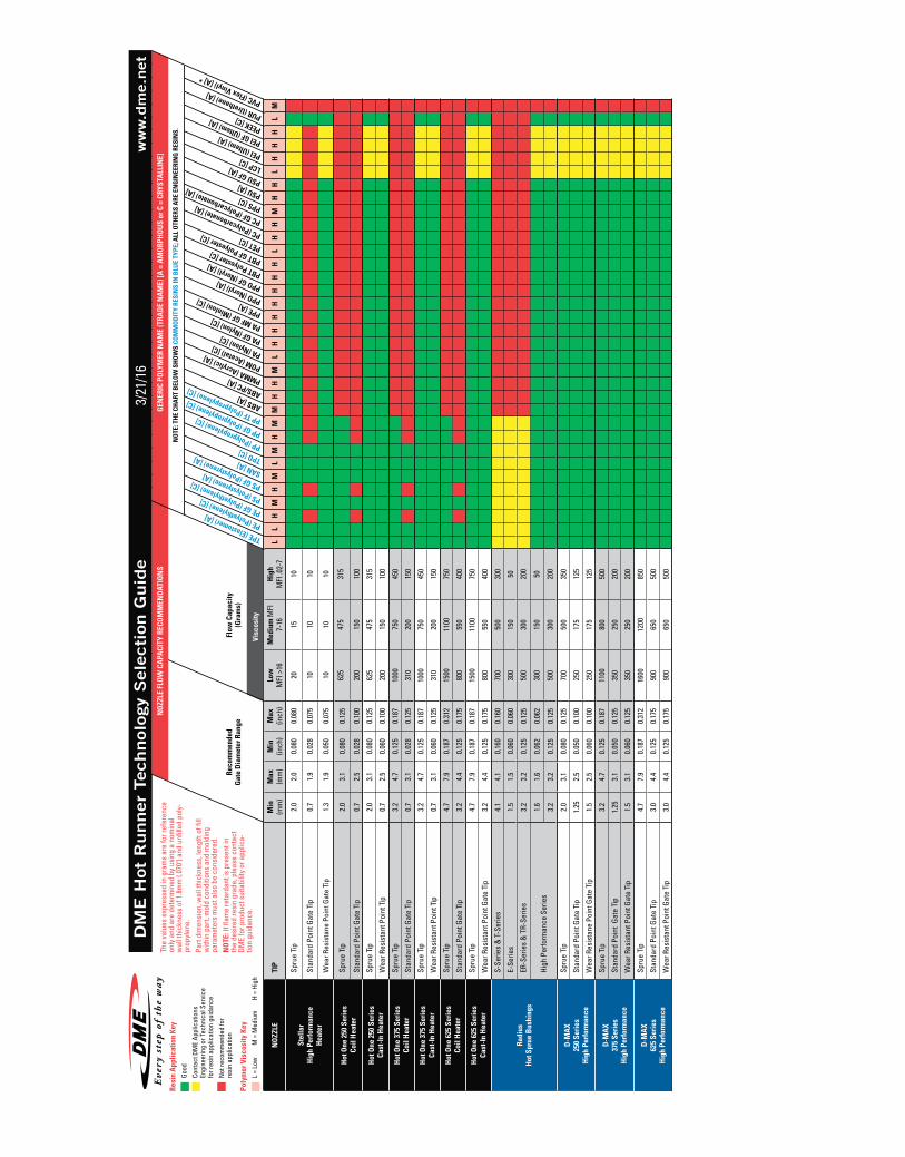
DM
E H
ot R
unner
Tec
hnol
ogy
Sel
ecti
on G
uid
ew
ww
.dm
e.net
3/21
/16

HO
T SP
RUE
BU
SHIN
G T
IP S
TYLE
SPRU
E G
ATE
TIP
ST
AN
DA
RD /
EXTE
ND
ED
For
use
whe
re g
ate
vest
ige
is a
llow
ed. P
rovi
des
low
res
ista
nce
to fl
ow w
ith
exce
llent
flow
rat
es.
Exte
nded
sty
le p
rovi
des
addi
tion
al s
tock
for
mac
hini
ng p
rofil
es o
r pa
rt c
onto
urs.
RIN
G G
ATE
TIP
ST
AN
DA
RD /
EXTE
ND
ED
Idea
l for
low
ves
tige
com
mod
ity
and
engi
neer
ing
grad
e re
sin
appl
icat
ions
. The
Rin
g G
ate
feat
ures
a se
aled
tip
for
effi
cien
t sh
ut-o
ff a
t th
e pa
rt s
urfa
ce. A
vaila
ble
wit
h st
anda
rd o
r w
ear
resi
stan
t
need
les.
Ext
ende
d st
yle
prov
ides
add
itio
nal s
tock
for
mac
hini
ng p
rofil
es o
r pa
rt c
onto
urs.
POIN
T G
ATE
TIP
Sui
tabl
e fo
r hi
gh v
isco
sity
res
ins,
eng
inee
ring
pla
stic
s an
d ap
plic
atio
ns r
equi
ring
opt
imum
gat
e
cosm
etic
s w
ith
min
imal
gat
e ve
stig
e. A
vaila
ble
wit
h st
anda
rd o
r w
ear
resi
stan
t ne
edle
s.
BU
SHIN
G T
IP A
ND
PLA
STIC
MAT
ERIA
L CO
MPA
TIB
ILIT
Y
NO
ZZLE
THER
MO
PLA
STIC
RES
IN T
YPE
AM
ORP
HO
US
SEM
I-CR
YSTA
LIN
E
SB
PUR *
PEI *
SAN *
PS
PC *
PPO *
PE
PP
PEEK
PPS *
PET *
PBT *
PA *
TPE *
POM *
PMMA *
ABS
TPO *
ABS/PC *
PPE/PS *
PSU
LCP
SPRU
E G
ATE
TIP
ST
AN
DA
RD /
EXTE
ND
ED
RIN
G G
ATE
TIP
ST
AN
DA
RD /
EXTE
ND
ED
POIN
T G
ATE
TIP
Gre
en
Yello
w
Red
– W
orks
wel
l wit
h th
is r
esin
– C
onta
ct D
ME
Engi
neer
ing
for
guid
ance
– N
ot r
ecom
men
ded
Bush
ing
Sel
ecti
onP
last
ic M
ater
ials
and S
pec
ific
atio
ns
PLA
ST
IC M
AT
ER
IAL
PR
OC
ES
S C
ON
DIT
ION
S
MAT
ERIA
L ST
AN
DA
RD R
ESIN
SY
MB
OL
PRO
CESS
TE
MPE
RATU
RE
MO
LD
TEM
PERA
TURE
H
OT
RUN
NER
TE
MPE
RATU
RE
DEN
SITY
M
ELTI
NG
SOLI
D
DEN
SITY
[°C]
[°F]
[°C]
[°F]
[°C]
[°F]
[g/c
m3 ]
[Ibs/
inch
3 ][g
/cm
3 ][Ib
s/in
ch3 ]
Styr
ene
Buta
dien
e SB
21
0 41
070
15
823
0 44
60.
93
0.03
661.
02
0.03
69
Poly
uret
hane
PU
R 22
0 42
845
11
324
0 46
40.
93
0.03
661.
11
0.04
01
Styr
ene-
acry
loni
trile
SA
N
230
446
80
176
255
491
0.99
0.
0358
1.08
0.
0390
Poly
styr
ene
PS
210
410
45
113
230
446
0.95
0.
0343
1.05
0.
0379
Poly
carb
onat
e PC
30
0 57
280
17
633
0 62
61.
08
0.03
901.
20
0.04
34
Poly
phen
ylen
e Ox
ide-
Styr
ene
PPO
260
500
80
176
300
572
0.99
0.
0358
1.13
0.
0408
Poly
ethy
lene
PE
20
0 39
225
77
225
437
0.74
0.
0267
0.96
0.
0347
Poly
prop
ylen
e PP
22
5 43
740
10
424
5 47
30.
73
0.02
640.
91
0.03
29
Poly
ethe
r-et
herk
eton
e PE
EK
330
626
165
329
370
698
1.13
0.
0408
1.37
0.
0495
Poly
phen
ylen
e Su
lfide
PP
S 30
0 57
211
0 23
033
0 62
61.
53
0.05
531.
70
0.06
14
Poly
ebut
ylen
e Te
reph
thal
ate
PBT
265
509
60
140
290
554
1.44
0.
0520
1.57
0.
0567
Poly
amid
e 6
PA 6
22
0 42
890
19
425
0 48
20.
98
0.03
541.
14
0.04
12
Poly
amid
e 66
PA 6
6 25
5 49
190
19
428
0 53
61.
09
0.03
941.
26
0.04
55
Ther
mal
Pla
stic
Ela
stom
ers
TPE
240
464
35
9526
5 50
90.
78
0.02
820.
90
0.03
25
Poly
oxym
ethy
lene
(Pol
yace
tal)
POM
18
0 35
610
0 21
220
0 39
21.
16
0.04
191.
42
0.05
13
Poly
met
hyl M
etha
cryl
ate
PMM
A 23
5 45
570
15
825
0 48
21.
09
0.03
941.
18
0.04
26
Acry
loni
trile
But
adie
ne S
tyre
ne
ABS
225
437
70
158
250
482
0.95
0.
0343
1.08
0.
0390
NO
TE: T
empe
ratu
re a
nd d
ensi
ty v
alue
s sh
own
abov
e ar
e ge
nera
l, an
d m
ay n
ot a
pply
to y
our
appl
icat
ion.
Ple
ase
refe
r to
prop
er p
roce
ssin
g da
ta fo
r the
resi
n gr
ade
inte
nded
for y
our s
peci
fic
appl
icat
ion.
Fai
lure
to u
se te
mpe
ratu
re s
ettin
gs a
ppro
pria
te to
the
spec
ific
resi
n an
d re
sin
grad
e in
tend
ed fo
r you
r app
licat
ion
may
resu
lt in
poo
r par
t qua
lity,
or i
nabi
lity
to p
rodu
ce a
ccep
tabl
e m
olde
d pa
rts.
13
U.S. 800-626-6653 Canada 800-387-6600 [email protected] www.dme.net
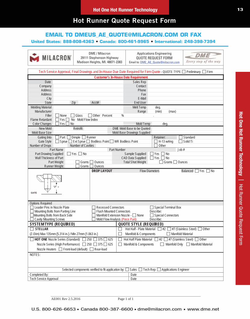
Hot Runner Quote Request Form
Ho
t On
e H
ot R
un
ner Te
ch
no
log
y | Hot Runner Q
uote Request FormHot One Hot Runner Technology
EMAIL TO [email protected] OR FAXUnited States: 888-808-4363 Canada: 800-461-9965 International: 248-398-7394
AE001 Rev 2.5.2016 Page 1 of 1
DME / Milacron 29111 Stephenson Highway
Madison Heights, MI. 48071-2383
Applications Engineering QUOTE REQUEST FORM
Email to: [email protected]
Tech Service Approval, Final Drawings and In-House Due Date Required for Firm Quote - QUOTE TYPE Preliminary Firm Customer’s In-House Date Requirement
Date Sales Rep Company Contact
Address Phone Address Fax
City E-Mail State Zip Acct# End User
Molding Material Melt Temp deg. Manufacturer Range (min) (max)
Filler None Glass Other Percent % Flame Retardant Yes No Mold Flow Index
Color Changes Yes No Mold Temp deg. New Mold Retrofit DME Mold Base to be Quoted
Mold Base Size Mold Base Drawings Supplied Gating Into Part Dimple Runner Retainer: Standard Gate Style Sprue Ext Sprue Bodiless Point WR Bodiless Point H-13 w/ring Solid Ti
Number of Drops Number of Cavities Other Part Name Part Number Job #
Part Drawing Supplied Yes No Sample Supplied Yes No Wall Thickness of Part CAD Data Supplied Yes No
Part Weight Grams Ounces Total Shot Weight Grams Ounces Runner Weight Grams Ounces
DROP LAYOUT Flow Diameters Balanced Yes No
Options Required Leader Pins in Nozzle Plate Recessed Connectors Special Terminal Box Mounting Bolts from Parting Line Flush Mounted Connectors Describe: Mounting Bolts from Back Side Manifold Extension Nozzle - None Special Connectors Cavity Mounting Screws Mold Flow Analysis (Piece Part) Describe:
SYSTEM TYPE (REQUIRED) QUOTE STYLE (REQUIRED) STELLAR Hot Half - Plate Material #2 #7 (Stainless Steel) Other
(Z-Dim) Max 135mm [5.314 in.] / Min 27mm [1.063 in.] Manifold & Components Manifold Material HOT ONE Nozzle Series (Standard) 250 375 625 Hot Half Plate Material #2 #7 (Stainless Steel) Other
Nozzle Series (High Performance) 250 375 625 Manifold & Components Mainfold Only Manifold Material Nozzle Heaters Front-load (default) Rear-load NOTES:
Selected components verified to fit application by: Sales Tech Rep Applications Engineer Completed By: Date Tech Service Approval Date

page content
text14C
usto
m H
ot
Ru
nn
er
Syste
ms |
In
dex
U.S. 800-626-6653 Canada 800-387-6600 [email protected] www.dme.net
Ho
t R
un
ner
Syste
ms |
In
dex
Table of Contents
Stellar Micromolding Hot Runner Systems.......... 19-23The best solution for precision thermoplastic
micromolding
Hot One Hot Runner Technology............................ 25-42A long-standing industry standard in
user-friendliness and affordability
Go to www.dme.net/prices for the latest pricing guide.Online Price Guide
14
Hot Runner Technology............................................ 15-17The best solution for precision thermoplastic
micromolding
Cartridge Heaters & Thermocouples.................... 36-42Custom-configured manifolds, manifold and
component systems, and complete hot half
assemblies for quick delivery
Meteor® Hot Runner Systems................................. 44-50Custom-configured manifolds, manifold and
component systems, and complete hot half
assemblies for quick delivery

Hot Runner Technology
A LONG-STANDING
INDUSTRY STANDARD
IN USER-FRIENDLINESS
AND AFFORDABILITY

16C
usto
m H
ot
Ru
nn
er
Syste
ms |
In
dex
U.S. 800-626-6653 Canada 800-387-6600 [email protected] www.dme.net
Features and Benefits
Hot Runner TechnologyH
ot
Ru
nn
er
Tech
no
log
y |
Fe
atur
es a
nd B
enef
its
Our ongoing customer-driven philosophy has
fostered many new and innovative systems and
components, allowing you to take advantage
of more than seven decades of leadership
in injection molding technology. DME’s Hot
Runner Technology has become an industry
standard in technology, user-friendliness, and
affordability. Available in two styles – Manifold
& Components and as a complete Hot Half
System.
Tubular Heated Systems
Using exclusive, distributed wattage Tubular
Heaters, the DME Hot Runner Systems can
process many engineering grade resins.
Tubular Heaters reduce the number of zones of
heat required, providing the added benefit of
lowering your temperature control costs.
DME’s Hot Runner Technology has become an industry standard in technology, user-friendliness, and affordability. Available in
two styles – Manifold & Components and as a complete Hot Half System.

text 17C
usto
m H
ot R
un
ner S
yste
ms | N
ew Products
U.S. 800-626-6653 Canada 800-387-6600 [email protected] www.dme.net
Ho
t Ru
nn
er S
yste
ms | N
ew Products
Nozzles
Ho
t On
e H
ot R
un
ner Te
ch
no
log
y | N
ozzlesHot Runner Technology
Nozzles The DME Hot One is accompanied by a nozzle offering
that allows versatility in system selection to best suit
the material and molded part configuration. DME offers
different styles of nozzles: The “EHA” series, using square
coil heaters and The “CIA” series, using High Performance
heaters. Each nozzle series has its own characteristics
and advantages.
For example, the “EHA” series of nozzles can be used
for many applications using commodity resins with low
crystallinity. The “CIA” series, with High Performance
heaters developed exclusively for DME, can be used for all
applications, especially engineering grade resins with a high
degree of crystallinity.
Ordering Options: Use this information and our design and machining guidelines to build your system, or take advantage
of DME Applications Engineering services to help you select the system best suited to your requirements. Then, either order the
steel and components to construct your system or let DME do all of the machining, assembly and wiring for you.
Each DME nozzle series has its own advantages and characteristics to meet your needs.
“CIA”/”EHA” Nozzles
Point Gate – Used for
applications needing optimum
gate cosmetics, this tip can run
a wide range of resins. It has
two interchangeable needles,
standard and wear resistant.
The wear resistant needle is
especially useful for abrasive
or filled material applications.
Sprue Gate/Extended Sprue Gate – Used primarily
in applications where gate
vestige is not a concern. Offers
minimal flow resistance and
handles most resins very
effectively. Extended style
provides additional stock for
machining of runner profiles or
part contours.
Full Body Point Gate – Used
for low vestige, commodity
grade resin applications. The
Ring Gate features a sealed
tip for efficient shut-off at the
parting line.
“EHA”/”CIA” Nozzle Tips
Stellar Nozzles
Point Gate
Sprue Gate

page content
text18
PROVEN SOLUTIONS
FOR PRECISION
THERMOPLASTIC
MICROMOLDING
Stellar MicromoldingHot Runner Systems

19
U.S. 800-626-6653 Canada 800-387-6600 [email protected] www.dme.net
Ste
llar M
icro
mo
ldin
g H
ot R
un
ner S
yste
ms | Stellar Hot Runner System
s – Benefits
Stellar Hot Runner Systems – Benefits
Engineered for the Challenges of Tight Pitch Molding
The DME Stellar™ Hot Runner System brings high performance, exacting
precision and flexible, cost-effective modular construction to very small part
molding. With as little as 17mm between centers, Stellar is also ideal for
high-cavitation molding.
Demand the Best – Demand DME
DME has been a leader in mold technologies for seven decades. Nobody
beats DME for quality products, quality service and quick delivery. Like all
DME products, Stellar Hot Runner Systems come with your satisfaction
100% guaranteed.
Get the Modular Advantage
Stellar is based on new DME hot runner system architecture to deliver
tremendous flexibility. Seven different “A” dimensions, two interchangeable
tip options, and a choice of manifold styles enable DME to easily configure
a Stellar solution that matches your application.
For a Wide Range of Applications
Stellar is perfect for today’s rapidly
expanding array of micromolding
projects. Stellar was designed to
perform in a broad spectrum of
applications – including electrical,
electronic, medical, and cosmetic
packaging. And, Stellar was
designed to process demanding
engineering resins without
property degradation.
Stellar Micromolding Hot Runner Systems

20
U.S. 800-626-6653 Canada 800-387-6600 [email protected] www.dme.net
Ste
lla
r M
icro
mo
ldin
g H
ot
Ru
nn
er
Syste
ms |
St
ella
r Hot
Run
ner S
yste
ms
– Be
nefit
s
Stellar Hot Runner Systems – Benefits
Excellent Results with Engineering Thermoplastics
The complexity of today’s very small part
molding applications demands the added properties of high
performance engineered materials.
Stellar was designed for outstanding processing of these
materials. Challenging amorphous materials such as PET or
crystalline materials including PBT and PA are easily processed
with the Stellar Hot Runner System. Highly conductive tip
designs and precise heat profiling in all nozzle lengths
ensure consistent processing temperatures.
Modularity Increases Application Flexibility
The Stellar Hot Runner System from DME is built on
a standardized architecture of modular components.
Key features include:
Seven different “A” dimensions from
65-145mm are available for compression style nozzles
Two interchangeable tip styles – Point Gate and Sprue Gate
High Performance Nozzle Heater with embedded thermocouple
Two tip material choices, standard and high performance
Stellar Micromolding Hot Runner Systems
To provide your Stellar®
application specifications, visit www.dme.net/cdc
CUSTOMER DESIGNCRITERIA FORMS
CDC

21
U.S. 800-626-6653 Canada 800-387-6600 [email protected] www.dme.net
Ste
llar M
icro
mo
ldin
g H
ot R
un
ner S
yste
ms | Stellar Hot Runner System
s Benefits
Stellar Hot Runner Systems Benefits
Stellar Micromolding Hot Runner Systems
High Process Temperature Capability with Precision Heat Profiling
Today’s engineered materials challenge hot runner systems with high processing temperatures – often with very narrow
operating windows. Stellar hot runner nozzles utilize reliable profiled mini-tubular heaters to ensure optimal heat distribution. In
addition, Stellar nozzles are engineered with low conductivity heads and high conductivity tips for consistent
thermal performance.
Easy Serviceability – Right in the Machine
Productivity is especially critical when micromolding thousands of parts per hour. Every Stellar Hot Runner System can be
rapidly serviced for maximum uptime. Nozzle tips, retainers, mini-tubular heaters and thermocouples are all front-loaded and
easily replaced with the mold in the press.
Increase Productivity and Reduce Molding Costs With Stellar-Infused Quick-Change Systems
Now the production efficiencies of hot runner molding can be further enhanced when combined with a Master Unit Die (MUD) Quick-Change Frame. An unlimited number of different parts can be produced with this industry-leading combination of hot runners within a quick-change system because only the MUD Companion Insert Mold is swapped out. The MUD Frame/Hot Runner System remains in the mold.
Combining DME Hot Runners with MUD Quick-Change Systems provides many advantages to virtually any injec-tion molding operation, including:
Enables molders to use the same DME Hot Runner System with many different cavity and core configurations with MUD Companion Insert Molds
Quickens production changeovers, often in as little as five minutes
Provides cost justification for the Hot Runner System and/or the MUD Quick-Change System for multiple tooling projects
Simplifies design with the use of the MUD Quick-Change Straps
Contact your DME representative or call us today to find out more about how the combination of a DME Hot Runner System and the MUD Quick-Change System will not only substantially increase your production efficiency but significantly reduce your molding costs. Many companies incorporate the DME hot runner/quick-change combo into their Lean initiatives.

22
U.S. 800-626-6653 Canada 800-387-6600 [email protected] www.dme.net
Ste
lla
r M
icro
mold
ing
Ho
t R
un
ner
Syste
ms |
Ga
ting
Styl
e Se
lect
ion
text22
Gating Style Selection
Stellar Systems
Gating Style Selection
Fig. 1 Standard Point Gate Tip Sub-Assembly, SXG5110
Fig. 4 Sprue Gate Tip, SXT7140 - T=.750
Table 1: Gating Style Item Numbers
Fig. 2 High Performance Point Gate Tip Sub-Assembly, SXG5020
Fig. 3 Sprue Gate Tip, SXT7040 - T=10mm
TIPSUB-ASSEMBLYITEM NUMBER DESCRIPTION
TIP ITEM
NUMBER
TIPCTE
(10-6/degC)
RETAINERITEM
NUMBERGATING STYLE
APPLICABLE STELLAR SYSTEM
SXG5110Standard
Point Gate Tip Sub-Assembly
SXT4010 17.5 SXF5100 Point Gate Standard
SXG5020High Performance Point Gate Tip Sub-
AssemblySXT5010 4.5 SXF5000 Point Gate High
Performance
N/A Sprue Gate Tip SXT7040 12.8 N/A Sprue Gate All
N/A Sprue Gate Tip SXT7140 12.8 N/A Sprue Gate All
NOTE: All units are in mm.

23
U.S. 800-626-6653 Canada 800-387-6600 [email protected] www.dme.net
Ste
llar S
yste
ms | Gate D
etails for use with Hardened Steel (50HRC m
in.)text 23
IN QUESTION
Gate Details for use with Hardened Steel (50HRC min.)
Stellar Systems
Gate Details for Standard Point Gate, High Performance Point Gate Tips (SXG5110 & SXG5020) For gating onto a flat surface or into a recess* (“dimple”)
Fig. 6
NOTES for Figure 6 & 7:1. If gate detail does not properly
fit the application, contact DME for assistance about gate detail options.
2. Position gate detail within ±0.013mm/.0005in from nominal.
3. The gate diameter can be opened by the customer to suit the application. (The land must be re-machined to the maximum dimension after increasing the gate diameter.)
4. Water lines are required in “A” plate for proper gate cooling.
5. Position water lines as close as possible but not closer than the minimum distance shown to provide a safe steel condition.
6. For faster color changes, remove (“decone”) the resin from the front of each point gate tip prior to changing colors.
7. The minimum “Z” dimension is 13.00 and the maximum “Z” dimension is 115 for point gate and sprue gate tips.
19.5 0.77SXT7140
19.050 + 0.0120.000 0.7500
+ 0.00050.0000
SXT7140
5.30
0.20
9
45°
20.
08 x
45
Z-D
IMEN
SIO
N
5 0.20MIN
5 0.20MIN
3.30 0.130MAX RUNNER
HEIGHT
19.0 0.75SXT7040
10.000 + 0.0050.000 0.3937
+ 0.00020.0000
SXT7040
30°
5mm/.20in MIN
Z DIMENSION
Ø2mm/0.08in x 45°
90° 30°
5mm/.20in MINDISTANCEBETWEEN
WATERLINEAND DROP
R3.18mm/.125in*
Ø19.0mm/0.75in
0.62mm/.024inTo Bottom of Radius
0.13mm/.005inMAX LAND
0.89mm/.035inMAX*
MIN GATE DIAMETERØ0.71mm/.028in for unfilled resinsØ1.27mm/.050in for filled resins
R0.25mm/.010in MINR0.38mm/.015in MAX
R4.76mm/.187in
R12.70mm/.500in MIN*
2.03mm /.080in+0.13 –0.00
+.005–.000
Ø9.800mm /.3858in+0.005 –0.000
+.0002–.0000
2.54mm /.100in+0.00 –0.13
+.000–.005
R 0.25mm/0.010in MINR 3.00mm/0.118in MAX
CLEARANCEDIAMETER
Gate Details for Sprue Gate Tips, SXT7040 & SXT7140Fig. 7

24C
usto
m H
ot
Ru
nn
er
Syste
ms |
In
dex
Ho
t R
un
ner
Syste
ms |
In
dex
Hot One Nozzles
ENABLING VERSATILITY
IN SYSTEM SELECTION

25C
usto
m H
ot R
un
ner S
yste
ms | N
ew Products
U.S. 800-626-6653 Canada 800-387-6600 [email protected] www.dme.net
Ho
t On
e N
ozzle
s | 250 Series N
ozzles (.250 Diam
eter Flow Channel)
250 Series Nozzles(.250 Diameter Flow Channel)
Hot One Nozzles
A B SUB-ASSEMBLY ITEM NUMBER
1 NOZZLE BODY
2 HEATER
3 SEAL RING
2.000
— EHA0001
CIB1359
SCH0081
EHR7154
1.250 EHA1001 SCH1081
— CIA0001S CIH0081S
1.250 CIA1001S CIH1081S
2.500
— EHA0002
CIB1360
SCH0082
1.250 EHA1002 SCH1082
— CIA0002S CIH0082S
1.250 CIA1002S CIH1082S
3.000
— EHA0003
CIB1361
SCH0083
1.250 EHA1003 SCH1083
— CIA0003S CIH0083S
1.250 CIA1003S CIH1083S
3.500
— EHA0004
CIB1362
SCH0084
1.250 EHA1004 SCH1084
— CIA0004S CIH0084S
1.250 CIA1004S CIH1084S
4.000
— EHA0005
CIB1363
SCH0085
1.250 EHA1005 SCH1085
— CIA0005S CIH0085S
1.250 CIA1005S CIH1085S
5.000
— EHA0006
CIB1364
SCH0086
1.250 EHA1006 SCH1086
— CIA0006S CIH0086S
1.250 CIA1006S CIH1086S
6.000
— EHA0007
CIB1365
SCH0087
1.250 EHA1007 SCH1087
— CIA0007S CIH0087S
1.250 CIA1007S CIH1087S
250 Series Nozzle Sub-Assembly
WIRING INFORMATION:Power leads are tan Ground leads are green Thermocouple leads are black and white
White is negative (-) and constantan (non-magnetic)
Black is positive (+) and iron (magnetic)
1.000
Ø0.250
A
Ø1.500 1
2
3
3
3
3
2
2
2
1
1
1
1/2-24 UN
SQUARE COIL HEATERREAR LOAD(SCH0XXX)
SQUARE COIL HEATERFRONT LOAD(SCH1XXX )
HIGH PERFORMANCE HEATERREAR LOAD(CIH0XXX-S)
HIGH PERFORMANCE HEATERFRONT LOAD(CIH1XXX-S)
B
B
Replacement Seal RingsUsed between manifold and nozzle to prevent leakage. New
seal rings must be installed each time manifold is assembled.
.56.06
(Add .750 to A dimension for extended sprue gate and extended full body point gate tips.)
ITEM NUMBER
EHR7154

26C
usto
m H
ot
Ru
nn
er
Syste
ms |
In
dex
U.S. 800-626-6653 Canada 800-387-6600 [email protected] www.dme.net
Ho
t O
ne N
ozzle
s
|
375
Serie
s Hi
gh P
erfo
rman
ce N
ozzl
es (.
375
Dia
met
er F
low
Cha
nnel
)
375 Series High Performance Nozzles(.375 Diameter Flow Channel)
Hot One Nozzles
A B SUB-ASSEMBLY ITEM NUMBER
1 NOZZLE BODY
2 HEATER
3 SEAL RING
2.000
— EHA0008
CIB1366
SCH0088
EHR7155
1.250 EHA1008 SCH1088
— CIA0008S CIH0088S
1.250 CIA1008S CIH1088S
2.500
— EHA0009
CIB1367
SCH0089
1.250 EHA1009 SCH1089
— CIA0009S CIH0089S
1.250 CIA1009S CIH1089S
3.000
— EHA0010
CIB1368
SCH0090
1.250 EHA1010 SCH1090
— CIA0010S CIH0090S
1.250 CIA1010S CIH1090S
3.500
— EHA0011
CIB1369
SCH0091
1.250 EHA1011 SCH1091
— CIA0011S CIH0091S
1.250 CIA1011S CIH1091S
4.000
— EHA0012
CIB1370
SCH0092
1.250 EHA1012 SCH1092
— CIA0012S CIH0092S
1.250 CIA1012S CIH1092S
5.000
— EHA0013
CIB1371
SCH0093
1.250 EHA1013 SCH1093
— CIA0013S CIH0093S
1.250 CIA1013S CIH1093S
6.000
— EHA0014
CIB1372
SCH0094
1.250 EHA1014 SCH1094
— CIA0014S CIH0094S
1.250 CIA1014S CIH1094S
7.000
— EHA0015
CIB1373
SCH0095
1.250 EHA1015 SCH1095
— CIA0015S CIH0095S
1.250 CIA1015S CIH1095S
375 Series Nozzle Sub-Assembly
WIRING INFORMATION:Power leads are tan Ground leads are green Thermocouple leads are black and white
White is negative (-) and constantan (non-magnetic)
Black is positive (+) and iron (magnetic)
1.000
Ø0.375
A
Ø2.000 1
2
3
3
3
3
2
2
2
1
1
1
5/8-20 UN
SQUARE COIL HEATERREAR LOAD(SCH0XXX)
SQUARE COIL HEATERFRONT LOAD(SCH1XXX)
HIGH PERFORMANCE HEATERREAR LOAD(CIH0XXX-S)
HIGH PERFORMANCE HEATERFRONT LOAD(CIH1XXX-S)
B
B
Replacement Seal Rings Used between manifold and nozzle to prevent leakage. New seal
rings must be installed each time manifold is assembled.
.68.06
(Add .750 to A dimension for extended sprue gate and extended full body point gate tips.)
ITEM NUMBER
EHR7155

27C
usto
m H
ot R
un
ner S
yste
ms | N
ew Products
U.S. 800-626-6653 Canada 800-387-6600 [email protected] www.dme.net
Hot O
ne N
ozzle
s | 625 Series High Perform
ance Nozzles (.625 D
iameter Flow
Channel)
625 Series Nozzles(.625 Diameter Flow Channel)
Replacement Seal Rings
Used between manifold and nozzle to prevent leakage. New seal rings must be installed each time manifold is assembled.
1.06.06
ITEM NUMBER
EHR7156
625 Series Nozzle Sub-Assembly (Add .750 to A dimension for extended sprue gate and extended full body point gate tips.)
WIRING INFORMATION:Power leads are tan Ground leads are green Thermocouple leads are black and white
White is negative (-) and constantan (non-magnetic)
Black is positive (+) and iron (magnetic)
Hot One Nozzles
3
2
1
B
1.500
Ø0.625
Ø3.000
A
1"-16 UN
2
13
A B SUB-ASSEMBLY ITEM NUMBER
1 NOZZLE BODY
2 HEATER
3 SEAL RING
3.000— CIA0023S
CIB1381CIH0104S
EHR7156
1.75 CIA1023S CIH1104S
4.000
— EHA0016 EHB0074
SCH0096
1.75 EHA1016 SCH1096
— CIA0016SCIB1374
CIH0096S
1.75 CIA1016S CIH1096S
5.000
— EHA0017 EHB0075
SCH0097
1.75 EHA1017 SCH1097
— CIA0017SCIB1375
CIH0097S
1.75 CIA1017S CIH1097S
6.000
— EHA0018EHB0076
SCH0098
1.75 EHA1018 SCH1098
— CIA0018SCIB1376
CIH0098S
1.75 CIA1018S CIH1098S
7.000
— EHA0019EHB0077
SCH0099
1.75 EHA1019 SCH1099
— CIA0019SCIB1377
CIH0099S
1.75 CIA1019S CIH1099S
8.000
— EHA0020 EHB0078
SCH0100
1.75 EHA1020 SCH1100
— CIA0020SCIB1378
CIH0101S
1.75 CIA1020S CIH1101S
9.000
— EHA0021EHB0079
SCH0101
1.75 EHA1021 SCH1101
— CIA0021SCIB1379
CIH0102S
1.75 CIA1021S CIH1102S
10.000
— EHA0022EHB0080
SCH0102
1.75 EHA1022 SCH1102
— CIA0022SCIB1380
CIH0103S
1.75 CIA1022S CIH1103S
2
3
1
2
3
B
1
High Performance HeaterRear Load
(CIH0XXX-S)
High Performance HeaterFront Load
(CIH1XXX-S)
Square Coil HeaterRear Load(SCH0XXX)
Square Coil HeaterFront Load(SCH1XXX)

28C
usto
m H
ot
Ru
nn
er
Syste
ms |
In
dex
U.S. 800-626-6653 Canada 800-387-6600 [email protected] www.dme.net
Ho
t O
ne N
ozzle
s |
Ga
te T
ip D
etai
l
Gate Tip Detail
Hot One Nozzles
Ø2.03
ØT
5° PER SIDE
C
E
5° PER SIDE
0.750
A
RETAINER TIP
NEEDLE
L
ØT
A
RETAINER TIP
NEEDLE
A
ØT ØO
E
RETAINER TIP
NEEDLE
A
ØO
ØT
SERIES GATE TIP ITEM NUMBER B DIA. T DIA. L C
250
SPRUE GATEEHT0010
.080
.500 .250 .375EHT0011 .750EHT0012 1.000 .100
1.125EXTENDED SPRUE GATEEHT0013 .500 1.000EHT0014 .750EHT0015 1.000 .850
375
SPRUE GATEEHT0016
.125
.500.250 .375EHT0017 .750
EHT0018 1.000
EXTENDED SPRUE GATEEHT0019 .500
1.000 1.125EHT0020 .750EHT0021 1.000
625SPRUE GATE EHT0022
.187 1.000.250 .500
EXTENDED SPRUE GATE EHT0023 1.000 1.250
Sprue Gate/Extended Sprue Gate
SERIES GATE TIP ITEM NUMBER T DIA.INCLUDES
NEEDLE RETAINER TIP
250STANDARD EHT0005
.375EHN0015 EHT0024
EHT1314 EHT0324
WEAR RESISTANT EHT1308 EHN0401 EHT0324 EHT1313 EHT1324
375STANDARD EHT0039
.500EHN0016 EHT0025
EHT1312 EHT0325
WEAR RESISTANT EHT1303 EHN0400 EHT0325 EHT1309 EHT1325
625STANDARD EHT1306
.625EHN0019 EHT1354
EHT1311 EHT0326
WEAR RESISTANT EHT1307 EHN0402 EHT0326 EHT1310 EHT1354
Point Gate (Bodiless)
(Add .750 to A dimension for extended sprue gate tips.)
SERIES TYPE ITEM NUMBER T DIA. O DIA. EINCLUDES
NEEDLE RETAINER TIP
250
STANDARD
EHT2001 .375 .060
.187
EHN0015
EHT0026 EHT2002 .080 EHT0027 EHT2003 .500 .060 EHT0028 EHT2004 .080 EHT0029
WEAR RESISTANT
EHT2005 .375 .060
EHN0401
EHT1326 EHT2006 .080 EHT1327 EHT2007 .500 .060 EHT1328 EHT2008 .080 EHT1329
375
STANDARD
EHT2009 .500 .080
.230
EHN0016
EHT0030 EHT2010 .100 EHT0031 EHT2011 .750 .080 EHT0032 EHT2012 .100 EHT0033 EHT2013 1.000 .080 EHT0034 EHT2014 .100 EHT0035
WEAR RESISTANT
EHT2015 .500 .080
EHN0400
EHT1330 EHT2016 .100 EHT1331 EHT2017 .750 .080 EHT1332 EHT2018 .100 EHT1333 EHT2019 1.000 .080 EHT1334 EHT2020 .100 EHT1335
625STANDARD EHT2021
1.000 .125 .250EHN0019 EHT0036
WEAR RESISTANT EHT2022 EHN0402 EHT1336
Point Gate (Full Body)
SERIES TYPE ITEM NUMBER T DIA. O DIA. EINCLUDES
NEEDLE RETAINER TIP
250
STANDARD
EHT2301 .375 .060
.938
EHN0015
EHT2326 EHT2302 .080 EHT2327 EHT2303 .500 .060 EHT2328 EHT2304 .080 EHT2329
WEAR RESISTANT
EHT2305 .375 .060
EHN0401
EHT2326 EHT2306 .080 EHT2327 EHT2307 .500 .060 EHT2328 EHT2308 .080 EHT2329
375
STANDARD
EHT2309 .500 .080
.980
EHN0016
EHT2330 EHT2310 .100 EHT2331 EHT2311 .750 .080 EHT2332 EHT2312 .100 EHT2333 EHT2313 1.000 .080 EHT2334 EHT2314 .100 EHT2335
WEAR RESISTANT
EHT2315 .500 .080
EHN0400
EHT2330 EHT2316 .100 EHT2331 EHT2317 .750 .080 EHT2332 EHT2318 .100 EHT2333 EHT2319 1.000 .080 EHT2334 EHT2320 .100 EHT2335
625STANDARD EHT2321
1.000 .125 1.000EHN0019
EHT2336WEAR RESISTANT EHT2322 EHN0402
Point Gate (Full Body Extended)
SERIES THREAD TYPE250 1/2-24 UN375 5/8-20 UN625 1"-16 UN

29C
usto
m H
ot R
un
ner S
yste
ms | N
ew Products
U.S. 800-626-6653 Canada 800-387-6600 [email protected] www.dme.net
Hot O
ne N
ozzle
s | Housing, N
ozzle Plate and Gate Machining D
imensions D
etailHot One Nozzles
Housing, Nozzle Plate and Gate Machining Dimensions Detail
SPRUE AND POINT GATE (FULL BODY)MACHINING DIMENSIONS
30°0'
+.0005 –.0000
“S” DIA..080 LAND
250 & 375 SERIESPOINT GATE (BODILESS)
MACHINING DIMENSIONS
.180
.100
.020
AT TANGENT
.010 –.015 RAD.
“0” DIA.
“Q” DIA.
.005LANDMAX.
30°0'“R” RAD.
+.0005 –.0000
80°
WATER LINES ARE RECOMMENDED IN HOUSING
RISER PAD HEIGHT
.261 DIA. HOLE THRU5/16–18 TAP
.34 DEEP2-PLC'S. TYP.
.219
.250 MIN.
.250 MIN.
SPACER RING AND SUPPORTPAD HEIGHT
A + BE
.25 MIN.
N DIA.1.000(1.500 FOR625 SERIES)
WATER LINES ARE RECOMMENDED IN "A" PLATE AND NOZZLE PLATE
1.875 NOZZLE PLATE RECOMMENDED
.125 RAD. MAX.
RECOMMENDED (.125 MIN.)
.250 MIN.+.001 –.000
F DIA.
G DIA.
H DIA.
J DIA.
MANIFOLDHEIGHT
K DIA.
M DIA.
.250
.625 WIRECHANNEL
.31 MIN.
HOUSING MUST BE EQUALTO RISER PADS, SPACERRING AND MANIFOLD ATROOM TEMPERATURE
Manifold Housing, Nozzle Plate, “A” Plate and Gate Machining Dimensions
NOTE: Extended sprue length will add .750 to land.
SERIES T DIA. S DIA.
250 AND 375
*.375 *.3755.500 .5005.750 .7505
1.000 1.0005625 1.000 1.0005
SERIES NOZZLE
O DIA.Q DIA. R RAD.UNFILLED
RESINFILLED RESIN
250 .028 MIN. .060 MIN. .3750 .125375 .028 MIN. .060 MIN. .5000 .187625 .080 MIN. .100 MIN. .6250 .312
*250 Point Gate (Full Body) only.NOTE: The “O” diameter can be opened by the
customer to suit the application. Also the land must be remachined to .005 max. after increasing the gate diameter.
SERIES K DIA.+.001 –.000
M DIA.
N DIA. MIN for SQ. COIL
N DIA. MIN for HIGH
PERFORMANCE250 1.56 1.501 1.062 1.187375 2.06 2.001 1.250 1.437625 3.06 3.001 1.875 2.125
NOZZLES
ITEM NUMBER F DIA. G DIA. H DIA. J DIA.
EHL0252 4.000 3.312 3.000 2.500
EHL0253 5.500 4.625 4.000 3.750
EHL0254 4.000 3.312 3.000 2.500
EHL0255 5.500 4.625 4.000 3.750
LOCATING RING
Manifold housing and insulator sheet are to be same width and length as mold base. Height of manifold housing to vary with stackup of manifold, riser pads and spacer rings.
NOTE: The expansion factor must be taken into consideration prior to machining for, and installing, nozzle. This expansion factor (BE) must then be added to the nominal “A” dimension.
Formula for determining this expansion factor is as follows: BE = “A” dimension x .00000633 x nozzle setpoint temp – 68°(assuming the mold is at 68˚F during
operation). If mold temperature is different, substitute 68˚F with actual mold temperature.EXAMPLE: Given a 3 inch “A” dimension, with a nozzle setpoint temp. of 500°:
BE = 3 x .0000063 x (500-68) = .008… thus A + BE = 3.008.The above information is only given as an example. Variations may occur based on mold configurations and cooling factor. In some instances, it may be necessary to obtain an empirical factor.
3
Ø2.125 MIN80°
30°
0.00
5 L
AND
MAX
0.02
0 A
T TA
NG.
0.12
50.
235
Ø0.6250 0.0000+0.0005
0.4
7
R0.312
R0.010-0.015
R0.125
ØO
625 SERIESPOINT GATE (BODILESS)
MACHINING DIMENSIONS

30C
usto
m H
ot
Ru
nn
er
Syste
ms |
In
dex
U.S. 800-626-6653 Canada 800-387-6600 [email protected] www.dme.net
Ho
t O
ne N
ozzle
s
| R
epla
cem
ent N
ozzl
e He
ater
Det
ail
Hot One Nozzles
Replacement Nozzle Heater Detail
Replacement Square Coil Nozzle Heater
SERIES ITEM NUMBER
D DIA. NOMINAL
NOZZLEL DIM. WATTS
USED WITH NOZZLE
SUB-ASSEMBLY
250
SCH0081
.625
2.000 300EHA0001
SHC1081 EHA1001SCH0082
2.500 350EHA0002
SCH1082 EHA1002SCH0083
3.000 400EHA0003
SCH1083 EHA1003SCH0084
3.500 425EHA0004
SCH1084 EHA1004SCH0085
4.000 500EHA0005
SCH1085 EHA1005SCH0086
5.000 500EHA0006
SCH1086 EHA1006SCH0087
6.000 550EHA0007
SCH1087 EHA1007
375
SCH0088
.875
2.125 400EHA0008
SCH1088 EHA1008SCH0089
2.625 450EHA0009
SCH1089 EHA1009SCH0090
3.125 550EHA0010
SCH1090 EHA1010SCH0091
3.625 700EHA0011
SCH1091 EHA1011SCH0092
4.125 800EHA0012
SCH1092 EHA1012SCH0093
5.125 900EHA0013
SCH1093 EHA1013SCH0094
6.125 1000EHA0014
SCH1094 EHA1014SCH0095
7.125 1100EHA0015
SCH1095 EHA1015
625
SCH0096
1.500
4.000 1000EHA0016
SCH1096 EHA1016SCH0097
5.000 1030EHA0017
SCH1097 EHA1017SCH0098
6.000 1100EHA0018
SCH1098 EHA1017SCH0099
7.000 1000EHA0019
SCH1099 EHA1019SCH0100
8.000 1200EHA0020
SCH1100 EHA1020SCH0101
9.000 1200EHA0021
SCH1101 EHA1021SCH0102 10.000 1200 EHA0022SCH1102 EHA1022
250, 375 AND 625 NOZZLE HEATER 240 VAC, T/C TYPE “J”, 36" LONG
D DIA.
L
WIRING INFORMATION:Power leads are black
Ground lead is green
Thermocouple leads are black and white
– White is negative (–) and constantan
(non-magnetic)
– Black is positive (+) and iron (magnetic)
Replacement High Performance Nozzle Heater
SERIES ITEM NUMBER
D DIA. NOMINAL
NOZZLEL DIM. WATTS
USED WITH NOZZLE
SUB-ASSEMBLY
250
CIH0081S
.625
2.000 300CIA0001S
CIH1081S CIA1001SCIH0082S
2.500 350CIA0002S
CIH1082S CIA1002SCIH0083S
3.000 400CIA0003S
CIH1083S CIA1003SCIH0084S
3.500 425CIA0004S
CIH1084S CIA1004SCIH0085S
4.000 425CIA0005S
CIH1085S CIA1005SCIH0086S
5.000 500CIA0006S
CIH1086S CIA1006SCIH0087S
6.000 550CIA0007S
CIH1087S CIA1007S
375
CIH0088S
.875
2.125 400CIA0008S
CIH1088S CIA1008SCIH0089S
2.625 450CIA0009S
CIH1089S CIA1009SCIH0090S
3.125 550CIA0010S
CIH1090S CIA1010SCIH0091S
3.625 700CIA0011S
CIH1091S CIA1011SCIH0092S
4.124 800CIA0012S
CIH1092S CIA1012SCIH0093S
5.125 900CIA0013S
CIH1093S CIA1013SCIH0094S
6.125 1000CIA0014S
CIH1094S CIA1014SCIH0095S
7.125 1100CIA0015S
CIH1095S CIA1015S
625
CIH0104S
1.500
3.038 847CIA0023S
CIH1104S CIA1023SCIH0096S
4.038 1000CIA0016S
CIH1096S CIA1016SCIH0097S
5.038 1030CIA0017S
CIH1097S CIA1017SCIH0098S
6.038 1100CIA0018S
CIH1098S CIA1018SCIH0099S
7.038 1000CIA0019S
CIH1099S CIA1019SCIH0101S
8.038 1200CIA0020S
CIH1101S CIA1020SCIH0102S
9.038 1200CIA0021S
CIH1102S CIA1021SCIH0103S
10.038 1200CIA0022S
CIH1103S CIA1022S
DDIA
LLENGTH

31C
usto
m H
ot R
un
ner S
yste
ms | N
ew Products
U.S. 800-626-6653 Canada 800-387-6600 [email protected] www.dme.net
Ho
t On
e N
ozzle
s | Standard Global M
anifold Replacement Heaters
Ho
t R
un
ner
Syste
ms |
St
anda
rd G
loba
l Man
ifold
Rep
lace
men
t Hea
ters
Hot Runner Systems
Standard Global Manifold Replacement Heaters
Replacing a DME Manifold Flexible Tubular Heater may also require the replacement of retaining rings that hold the heater in place. After installing the manifold heater, insert a retaining ring into each of the existing undercut grooves in the manifold. Use a brass hammer to lightly tap a small piece of brass and each retaining ring to secure the manifold heater.
DME Manifold Flexible Replacement Heaters
HIGH-WATT FLEXIBLE TUBULAR HEATERS
ITEM NO. LENGTH (mm) WATTAGEHFH8030 300 660HFH8035 350 675HFH8040 400 795HFH8045 450 910HFH8050 500 1025HFH8055 550 1145HFH8060 600 1260HFH8065 650 1380HFH8070 700 1495HFH8075 750 1615HFH8080 800 1730HFH8085 850 1845HFH8090 900 1960HFH8095 950 2080HFH8100 1000 2195HFH8105 1050 2316HFH8110 1100 2430HFH8115 1150 2545HFH8120 1200 2665HFH8125 1250 2780HFH8130 1300 2895HFH8135 1350 3015HFH8140 1400 3130HFH8145 1450 3245HFH8150 1500 3365
8.0mm diameter. Operating voltage 240 Volt. Threaded pins on both ends.
Image not to scale.
OPTIONAL ITEM
RR-472-13000-100 Manifold Heater Retainer Clips
Heater Retainer Clips
Undercut Grooves
Length (tolerance +/- 1.5%)
Flexible Heated LengthUnflexible Unheated(min. 30mm)
Unflexible Unheated(min. 30mm)
Ceramic
~20mm
~6mm
321 Stainless Steel
LOW-WATT FLEXIBLE TUBULAR HEATERS
ITEM NO. LENGTH (mm) WATTAGEHFL8040 400 339
HFL8045 450 364
HFL8050 500 410
HFL8055 550 458
HFL8060 600 504
HFL8065 650 552
HFL8070 700 598
HFL8075 750 646
HFL8080 800 692
HFL8085 850 738
HFL8090 900 784
HFL8095 950 832
HFL8100 1000 878
HFL8105 1050 926
HFL8110 1100 972
HFL8115 1150 1018
HFL8120 1200 1066
HFL8125 1250 1112
HFL8130 1300 1158
HFL8135 1350 1206
HFL8140 1400 1252
HFL8145 1450 1298
HFL8150 1500 1346
NOTE: Low-watt 240V heaters are non-stock items - 4 week lead time.

32C
usto
m H
ot
Ru
nn
er
Syste
ms |
In
dex
U.S. 800-626-6653 Canada 800-387-6600 [email protected] www.dme.net
Ho
t R
un
ner
Syste
ms |
St
anda
rd G
loba
l Man
ifold
Rep
lace
men
t Hea
ters
Standard Global Manifold Replacement Heaters
Hot Runner Systems
Replacing a DME Manifold Flexible Tubular Heater may also require the replacement of retaining rings that hold the heater in place. After installing the manifold heater, insert a retaining ring into each of the existing undercut grooves in the manifold. Use a brass hammer to lightly tap a small piece of brass and each retaining ring to secure the manifold heater.
DME Manifold Flexible Replacement Heaters
HIGH-WATT FLEXIBLE TUBULAR HEATERS
ITEM NO. LENGTH (mm) WATTAGEHFH850300 300 650
HFH850350 350 750
HFH850400 400 900
HFH850450 450 1050
HFH850500 500 1150
HFH850550 550 1300
HFH850600 600 1450
HFH850650 650 1600
HFH850700 700 1750
HFH850750 750 1900
HFH850800 800 2050
HFH850850 850 2200
HFH850900 900 2350
HFH850950 950 2500
HFH851000 1000 2650
HFH851050 1050 2800
HFH851100 1100 2930
HFH851150 1150 3060
HFH851200 1200 3190
HFH851250 1250 3320
HFH851300 1300 3450
HFH851350 1350 3580
HFH851400 1400 3710
HFH851450 1450 3840
HFH851500 1500 3970
8.5mm diameter. Operating voltage 230 Volt. Threaded pins on both ends.
Length (tolerance +/- 1.5%)
Flexible Heated LengthUnflexible Unheated(min. 30mm)
Unflexible Unheated(min. 30mm)
Ceramic
~20mm
~6mm
321 Stainless Steel
LOW-WATT FLEXIBLE TUBULAR HEATERS
ITEM NO. LENGTH (mm) WATTAGEHFL850500 500 700
HFL850550 550 780
HFL850600 600 860
HFL850650 650 950
HFL850700 700 1000
HFL850750 750 1100
HFL850800 800 1190
HFL850850 850 1250
HFL850900 900 1350
HFL850950 950 1430
HFL851000 1000 1500
HFL851050 1050 1590
HFL851100 1100 1650
HFL851150 1150 1750
HFL851200 1200 1830
HFL851250 1250 1900
HFL851300 1300 1990
HFL851350 1350 2070
HFL851400 1400 2150
HFL851450 1450 2230
HFL851500 1500 2300
Image not to scale.
OPTIONAL ITEM
RR-472-13000-100 Manifold Heater Retainer Clips
Heater Retainer Clips
Undercut Grooves

33C
usto
m H
ot R
un
ner S
yste
ms | N
ew Products
U.S. 800-626-6653 Canada 800-387-6600 [email protected] www.dme.net
Ho
t On
e N
ozzle
s | Replacem
ent Parts Detail
Hot One Nozzles
Replacement Parts Detail
Terminal Mounting Box For information on terminal mounting boxes, mold power and thermocouple connectors, see the DME Control Systems Catalog.
Locating Ring Machining Relief in top of manifold for locating ring.
Nozzle Seat Machining
ITEM NUMBER M THREAD SIZE
EHN0011 .687 DIA. HOLE × .56 DEEP3⁄4–16 UNF TAP × .50 DEEPEHN0012
EHN0013 .922 DIA. HOLE × .69 DEEP1–12 UNF TAP × .62 DEEPEHN0014
Nozzle Seat Replaceable interface between manifold and machine nozzle.
ITEM NUMBER
SPH. RAD. X L C
DIM.D
HEX.E
DIA.F
DIA. THREAD
EHN0011 .500.62 1.250 1.250 1.50 .363 .312 3⁄4 –16
EHN0012 .750EHN0013 .500
.75 1.750 1.500 1.88 .457 .375 1–12EHN0014 .750
C DIA.D HEX.(ACROSS FLATS)SPH. RAD.
L
X
E DIA.THREAD UNF
.25 FOR EHN0011 & EHN0012
.38 FOR EHN0013 & EHN0014
F DIA.
Locating Ring INCLUDES (2) 5⁄16 – 18 × 1⁄2" LG. FLAT HEAD CAP SCREWS
ITEM NUMBER
D DIA.
X DIA.
Y DIA.
A DIM.
B DIA.
C DIM.
EHL0252 2.990 2.000 2.500 3.312 3.990 2.875EHL0253 3.990 3.250 3.750 4.625 5.495 2.875EHL0254 2.990 2.000 2.500 3.312 3.990 4.500EHL0255 3.990 3.250 3.750 4.625 5.495 4.500
DX
C
Y
.218
1.500
AB
M THREAD SIZE
N DIA.
.12 .50
ITEM NUMBER N DIA.
EHL0252 2.505EHL0253 3.755EHL0254 2.505EHL0255 3.755
+.005 –.000
C DIA.
.12
B DIA.
A A
Drool RingsUsed in conjunction with nozzle seat and locating ring to prevent
nozzle purging and drooling from entering manifold area.
See application information on the preceding page for appropriate use of nozzle seats, drool rings and locating rings.
ITEM NUMBER
B DIA.
C DIA.
EHL1001 1.382.19
EHL1002 1.62
EHL1003 1.383.44
EHL1004 1.62

34C
usto
m H
ot
Ru
nn
er
Syste
ms |
In
dex
U.S. 800-626-6653 Canada 800-387-6600 [email protected] www.dme.net
Ho
t O
ne C
om
po
nen
ts |
Co
mpo
nent
s fo
r Ext
erna
lly H
eate
d M
anifo
ld S
yste
ms
Components for Externally Heated Manifold Systems
Hot One Components
H
.78 DIA..19
.06 1.41 DIA.
1.75 DIA.
DRILLED & C'BORED FOR¼-20 LOW HEAD SCREW"X" DEEP
H
.78 DIA..19
.06 1.41 DIA.
1.06 DIA..375 DIA.
1.75 DIA.
DRILLED & C'BORED FOR¼-20 LOW HEAD SCREW"X" DEEP 2 PLACES
Used primarily with tubular heated manifolds, these components are made from
a non-magnetic material with low thermal conductivity. They provide the higher
efficiency and performance required for tubular manifold applications.
Riser Pads Supports manifold opposite nozzles and prevents heat loss.
Center Support Pads and Tubular Dowels Supports manifold center spacing, while minimizing heat transfer from manifold.
H
.78 DIA.
DRILLED & C'BORED FOR¼-20 LOW HEAD SCREW"X" DEEP
ITEM NUMBER H X
ERP1001 .500 .405
ERP1002 .750 .655
ITEM NUMBER H X
ERP1011 .500 .405
ERP1012 .750 .655
H
.250 DIA.
.375 DIA.
ITEM NUMBER H X
ECB1001 .500 .405
ECB1002 .750 .655
ITEM NUMBER
L LENGTH
3834TD .750
38114TD 1.250

35C
usto
m H
ot R
un
ner S
yste
ms | N
ew Products
U.S. 800-626-6653 Canada 800-387-6600 [email protected] www.dme.net
Ho
t On
e N
ozzle
s | Parts D
etail
INCLUDES (2) #10–24 LOW HEAD CAP SCREWS
ITEM NUMBER X DIM. +.010 –.000 L DIM. F DIM. G DIA. USED WITH
ERP0163 .2504.000 3.250 .625
GATE-MATE 4, 250 SERIES AND
375 SERIESERP0167 .375ERP0164 .750ERP0165 .250
5.000 4.000 .781 625 SERIESERP0168 .375ERP0166 .750
Hot One Nozzles
Parts Detail
Riser Pad Supports manifold opposite nozzles. Prevents heat loss and maintains spacing between manifold and clamping plate.
F1.125
X L
G DIA.
Center Support Pad Aligns and supports manifold center while minimizing heat transfer from manifold.
P DIA.
FOR .250 DIA. DOWELX
Tapered Dowel Pin Aligns and prevents end plug from rotating. Tapered
dowel pin must conform to ANSI B18.8.2-1978 standard.
.162 DIA..193 DIA.
1.50
ITEM NUMBER
EDP0001
End Plug Used to plug horizontal flow channels.
H DIA.+.0000.0002
+.001.000K
M
J DIA.
#10–24 TAP
Material : P–20
SERIES ITEM NUMBER H DIA. J DIA. K DIM. M DIM.GATE-MATE 4 EEP0002 .5615 .800 .750 1.500
250 EEP0001 .4365 .675 .750 1.500375 EEP0002 .5615 .800 .750 1.500625 EEP0003 .6875 .894 1.125 1.875
End Plug Set Screw Used to secure end plug into manifold (2 required). End plug
set screw must conform to the following standards.
ANSI B1.1. ANSI B18.3 and ASTM F912.
SERIES ITEM NUMBER THREAD N DIM.GATE-MATE 4 SSS7878 7⁄8–14 UNF-3A .875
250 SSS3434 3⁄4–16 UNF-3A .750375 SSS7878 7⁄8–14 UNF-3A .875625 SSS11 1–12 UNF-3A 1.000
THREAD
N
Heater Stop Machining Used for ECH-Series cartridge heaters.
. 201 DIA. HOLE .625 DEEP1/4–20 UNC TAP .50 DEEP
HEATER HOLE
.406
1/4–20 .38 LG. BUTTON HEAD CAP SCREWMOLDMAKER TO SUPPLY
Heater Puller Machining Used for CHS-Series cartridge heaters recommended for
heaters installed in blind holes.
.687 DIA. HOLE .75 DEEP3/4 16 UNF TAP .68 DEEP
ITEM NUMBER X DIM. P DIA.ECB0161 .250 2.500ECB0162 .750 2.500ECB0163 .250 1.500ECB0164 .750 1.500
+.010 –.000
Spacer RingMaintains spacing between manifold and nozzle plate.
X
.875DIA.
A DIA.
ITEM NUMBER X DIM. +.010 –.000 A DIA. USED WITH
ESR0157 .250.406 GATE-MATE 4, 250
SERIES AND 375 SERIESESR0158 .750ESR0159 .250
.531 625 SERIESESR0160 .750

36C
usto
m H
ot
Ru
nn
er
Syste
ms |
In
dex
U.S. 800-626-6653 Canada 800-387-6600 [email protected] www.dme.net
Ho
t O
ne N
ozzle
s |
Ca
rtrid
ge H
eate
rs &
The
rmoc
oupl
es
Cartridge Heaters & Thermocouples
Hot One Nozzles
.28 DIA.
L
Although these heaters do not employ integral
thermocouples, they’re designed and constructed to run at
higher molding temperatures and provide longer life than
conventional heaters.
NOTE: Sizes preceded by an * are the newest additions.
See the Hot One Design and Machining Guidelines at the end of this Hot One Nozzles section for manifold size recommendation and installation drawings.
Cartridge Heaters.500 DIAMETER NOMINAL
ITEM NUMBER
LENGTH L WATTS
WATTS PER
LIN. IN.
ECH0103 4.0 500 125ECH0119 4.0 750 188ECH0104 4.5 575 128
* ECH0138 5.0 500 100ECH0105 5.0 650 130
* ECH0139 5.0 750 150ECH0120 5.0 1000 200
* ECH0148 5.5 500 91ECH0106 5.5 725 132
* ECH0140 6.0 750 125ECH0107 6.0 800 133ECH0121 6.0 1000 167ECH0108 6.5 875 135
* ECH0141 7.0 600 86ECH0109 7.0 950 136ECH0122 7.0 1000 143
* ECH0149 7.5 1000 133ECH0110 7.5 1025 137
* ECH0142 8.0 1000 125ECH0111 8.0 1100 138ECH0123 8.0 1500 188ECH0124 8.0 2000 250ECH0112 8.5 1175 138ECH0113 9.0 1200 133ECH0114 10.0 1350 135ECH0125 10.0 1500 150ECH0126 11.0 1000 91ECH0115 11.0 1500 136ECH0128 12.0 1000 83ECH0127 12.0 1500 125ECH0116 12.0 1650 137
* ECH0144 12.0 2000 167* ECH0146 14.0 1000 71* ECH0145 14.0 2300 164
ECH0129 15.0 1500 100ECH0117 15.0 2050 137
* ECH0147 18.0 1500 83ECH0130 18.0 1700 94ECH0118 18.0 2500 139
Shoulder Style Cartridge Heaters
ITEM NUMBER
L IN
INCHESWATTS
WATTS PER
LIN. IN.
CHS0119 4.0 500 125CHS0120 4.5 575 128CHS0121 5.0 650 130CHS0122 5.5 725 132CHS0123 6.0 800 133CHS0124 6.5 875 135CHS0125 7.0 950 136CHS0126 7.5 1025 137CHS0127 8.0 1100 138CHS0128 8.5 1175 138CHS0129 9.0 1200 133CHS0130 10.0 1350 135CHS0131 11.0 1500 136CHS0132 12.0 1650 137CHS0133 15.0 2050 137CHS0134 18.0 2500 139
.500
¾-16 THREAD
.81HEX
.81
1.625
Snap Ring(Included)
ITEM NUMBER
EHP0250
Heater Puller (with Snap Ring) Provides trouble-free removal of
Shoulder Style Cartridge Heater.
PULLER WITH RING
REPLACEMENT SNAP RINGS
ITEM NUMBER*
EHP0001
*Pkg. of 25
L
.500 DIA. NOMINAL
Heater puller to be ordered separately.
240 VAC, 36" Leads with 6" of Lead Protection
Flat Washer TypeUtilized in limited
space applications.
Manifold Thermocouples Installed in manifold to maintain precise temperature control.
Threaded TypeInstalled between heat
source and flow channel
for more precise control.
ITEM NUMBER
ETC0168
ITEM NUMBER
ETC0251
Cartridge Heater – Power Leads are multi-colored
Shoulder Style Cartridge Heater
Cartridge Heaters Can be installed through hole
or installed using retainer plate
construction.
Shoulder Style Cartridge Heaters These heaters are used in
conjunction with heater pullers
to insure easy removal of blind
or through hole installations.
1/4 – 28 UNF
.375

37C
usto
m H
ot R
un
ner S
yste
ms | N
ew Products
U.S. 800-626-6653 Canada 800-387-6600 [email protected] www.dme.net
Hot One ComponentsH
ot O
ne C
om
po
nen
ts | Cartridge Heaters
Cartridge Heaters
NOTE: Special heaters are available on special order.
DME Standard Cartridge heaters employ a swaged
construction using the finest resistance wire and insulation
available for optimum heating performance, long life and
maximum dependability. These heaters are furnished with
10" long flexible lead wires, ready for fast installation.
Thermocouple cartridge heaters are also available.
NOTE: Lead wires can withstand temperatures up to 450°F. If temperatures will exceed this amount, leads must be insulated.
DIA.LENGTH(INCHES) VOLTS WATTS ITEM NUMBER
5/8
2 120 100 CU50212 240 100 CU50223 240 200 CU50324 240 250 CU50425 120 300 CU50515 240 300 CU50526 120 375 CU50616 240 375 CU50628 120 500 CU50818 240 500 CU508210 120 650 CU510110 240 650 CU510212 120 775 CU512112 240 775 CU512214 240 900 CU514216 240 1050 CU5162
3/4
3 240 225 CU60324 120 300 CU60414 240 300 CU60425 120 375 CU60515 240 375 CU60526 120 450 CU60616 240 450 CU60628 120 600 CU60818 240 600 CU608210 120 800 CU610110 240 800 CU610212 120 950 CU612112 240 950 CU612214 240 1100 CU614216 240 1250 CU6162
DIA.LENGTH(INCHES) VOLTS WATTS ITEM NUMBER
1/4
2 120 40 CU20212 240 40 CU20223 120 75 CU20313 240 75 CU20324 120 100 CU20414 240 100 CU20426 120 150 CU20616 240 150 CU2062
3/8
2 120 75 CU30212 240 75 CU30223 120 100 CU30313 240 100 CU30324 120 150 CU30414 240 150 CU30425 120 185 CU30515 240 185 CU30526 120 225 CU30616 240 225 CU30628 120 300 CU30818 240 300 CU3082
1/2
2 120 75 CU40212 240 75 CU40223 120 150 CU40313 240 150 CU40324 120 180 CU40414 240 180 CU40425 120 200 CU40515 240 200 CU40526 120 300 CU40616 240 300 CU40628 120 400 CU40818 240 400 CU4082
10 120 500 CU410110 240 500 CU410212 120 600 CU412112 240 600 CU412216 120 800 CU416116 240 800 CU4162

38C
usto
m H
ot
Ru
nn
er
Syste
ms |
In
dex
U.S. 800-626-6653 Canada 800-387-6600 [email protected] www.dme.net
Ho
t O
ne C
om
po
nen
ts |
Hi
gh W
att D
ensi
ty C
artr
idge
Hea
ters
High Watt Density Cartridge Heaters
Hot One Components
NOTE: Lead wires can withstand temperatures up to 450°F. If temperatures will exceed this amount, leads must be insulated.
Fit TolerancesThe cavity or hole, into which a cartridge heater is
inserted, should be reamed* to the nominal diameter of
the heater. DME cartridge heater diameters are actually
.002 to .007 undersize. High Watt Density Cartridge
Heaters are .004 undersize, held to a tolerance of ±.002.
This sizing is maintained for easy installation and for best
heat transfer. However, if close hole tolerances are not
maintained, operating life of the heater may be drastically
reduced. Also make sure that the heated area of the
cartridge does not extend beyond the hole.
Spacing of HeatersAs a general rule it is not recommended to space heaters
in a mold, die or platen any closer to each other than the
diameter of the heater.
ContaminationContamination consists of any foreign matter such as
plastics, oil, grease, dirt or water entering through the
terminal end or the end opposite the terminal. Care must
be taken to protect the heater or these contaminants will
shorten the effective heater life.
Proper Care and Maintenance1. Heaters should be stored in a dry area, especially
during periods of excess humidity.
2. Protect leads from abuse, abrasion, fatigue, etc.
3. Maintain temperature controllers and accessories
in good working condition to avoid an overheating
condition.
4. Transferring heaters from one die or platen to another
is not recommended.
* See DME Equipment and Supplies Catalog for DME machine reamers and DME straight shank long drills.
DIA.LENGTH(INCHES) VOLTS WATTS ITEM NUMBER
1/4
1 120 100 CM10011 240 100 CM1002
11/2 120 150 CM112111/2 240 150 CM1122
2 120 200 CM20212 240 200 CM20223 120 300 CM20313 240 300 CM20324 240 375 CM20425 240 450 CM2052
3/8
2 240 250 CM30223 240 350 CM30324 240 500 CM30425 240 550 CM30526 240 600 CM3062
1/2
2 240 250 CM40223 240 300 CM40324 240 400 CM40425 240 800 CM40526 240 1000 CM40628 240 1200 CM4082
10 240 1500 CM410212 240 2000 CM4122
5/8
2 240 300 CM50224 240 700 CM50426 240 1000 CM50628 240 1200 CM50829 240 1400 CM5092
10 240 1500 CM510214 240 2000 CM5142
3/4
2 240 300 CM60224 240 750 CM60426 240 1200 CM6062
10 240 1600 CM610214 240 2200 CM6142
DME High Watt Density Cartridge Heaters employ swaged
construction for maximum heat transfer and high watt density
for more demanding applications. Recommended for use when
will be subjected to vibration. Furnished with 10" long flexible
lead wires. Special heaters are available on special order.
Thermocouple cartridge heaters are also available.
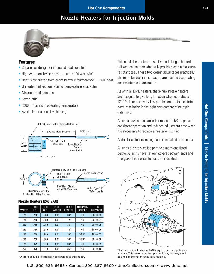
39C
usto
m H
ot R
un
ner S
yste
ms | N
ew Products
U.S. 800-626-6653 Canada 800-387-6600 [email protected] www.dme.net
Hot One ComponentsH
ot O
ne C
om
po
nen
ts | N
ozzle Heaters for Injection Molds
Nozzle Heaters for Injection Molds
This installation illustrates DME’s square coil design fit over a nozzle. This heater was designed to fit any industry nozzle as a replacement for runnerless molding.
Features Square coil design for improved heat transfer
High watt density on nozzle … up to 106 watts/in2
Heat is conducted from entire heater circumference … 360˚ heat
Unheated tail section reduces temperature at adapter
Moisture-resistant seal
Low profile
Available for same-day shipping
430 SS Band Rolled Over to Retain Coil
5.00" No-Heat Section
.28"
CoilWidth
Coil I.D.
3/16" Dia.
IdentificationData on
Heat Shrink
2F Style LeadOrientation
Reinforcing Clamp Tab RetainersBrazed Connection.094" Dia. 304
SS Sheath
22 Ga. Type “E”Teflon Leads#6-32 Stainless Steel
Socket Head Cap Screws
PVC Heat Shrinkwith FEP Melt Liner
*A thermocouple is externally spotwelded to the sheath.
WATTSCOIL I.D.
COIL O.D.
COIL WIDTH
LEAD LENGTH
THERMO- COUPLE
ITEMNUMBER
125 .750 .980 1.0" 36" NO SCH0103
125 .750 .980 1.0" 72" NO SCH0104
250 .750 .980 1.0" 36" NO SCH0105
250 .750 .980 1.0" 72" NO SCH0106
125 .750 .980 1.0" 36" YES* SCH0107
250 .750 .980 1.0" 36" YES* SCH0108
125 .875 1.10 1.0" 36" NO SCH0109
250 .875 1.10 1.0" 36" NO SCH0110
Nozzle Heaters (240 VAC)
This nozzle heater features a five-inch long unheated
tail section, and the adapter is provided with a moisture-
resistant seal. These two design advantages practically
eliminate failures in the adapter area due to overheating
and moisture contamination.
As with all DME heaters, these new nozzle heaters
are designed to give long life even when operated at
easy installation in the tight environment of multiple
gate molds.
All units have a resistance tolerance of ±5% to provide
consistent operation and reduced adjustment time when
it is necessary to replace a heater or bushing.
A stainless steel clamping band is installed on all units.
All units are stock coiled per the dimensions listed
below. All units have Teflon® covered power leads and
fiberglass thermocouple leads as indicated.

40C
usto
m H
ot
Ru
nn
er
Syste
ms |
In
dex
U.S. 800-626-6653 Canada 800-387-6600 [email protected] www.dme.net
Ho
t O
ne C
om
po
nen
ts |
Hi
gh W
att D
ensi
ty T
herm
ocou
ple
Cart
ridge
Hea
ters
High Watt Density Thermocouple Cartridge Heaters
Hot One Components
These diagrams show typical installations of a thermocouple replacement cartridge heater.
DME High Watt Density Thermocouple Cartridge
Heaters employ swaged construction for maximum
heat transfer and high watt density for more
demanding applications. Recommended for use
or where heaters will be subjected to vibration.
Fit TolerancesThe cavity or hole into which a cartridge heater is
inserted should be reamed* to the nominal diameter
of the heater. DME cartridge heater diameters are
actually .002 to .007 undersize. High Watt Density
Cartridge Heaters are .003 undersize, held to a
tolerance of ±.002. This sizing is maintained for easy
installation and for best heat transfer. However, if
close hole tolerances are not maintained, operating
life of the heater may be drastically reduced. Also
make sure that the heated area of the cartridge does
not extend beyond the hole.
ContaminationContamination consists of any foreign matter such
as plastics, oil, grease, dirt or water entering through
the terminal end or the end opposite the terminal.
Care must be taken to protect the heater or these
contaminants will shorten the effective heater life.
Proper Care and Maintenance1. Heaters should be stored in a dry area,
especially during periods of excess humidity.
2. Protect leads from abuse, abrasion, fatigue, etc.
3. Maintain temperature controllers and
accessories in good working condition to avoid
an overheating condition.
4. Transferring heaters from one die or platen to
another is not recommended.
* See DME Equipment and Supplies Catalog for DME machine reamers and DME straight shank long drills.
DIAMETER
LENGTHS
VOLTS WATTSITEM
NUMBERIN CM
3/8"(9.42mm)
1 3/4 4.445 240 200 TCH0001
2 5.08 240 250 TCH0002
2 1/2 6.35 240 250 TCH0003
3 7.52 240 250 TCH0004
3 1/2 8.39 240 320 TCH0005
4 10.15 240 370 TCH0006
4 1/2 11.43 240 420 TCH0007
5 12.70 240 470 TCH0008
5 1/2 13.97 240 525 TCH0009
6 15.24 240 575 TCH0010
6 1/2 16.51 240 625 TCH0011
7 17.78 240 675 TCH0012
7 1/2 19.05 240 725 TCH0013
8 20.32 240 775 TCH0014
1/2"(12.50mm)
3 1/2 8.89 240 420 TCH0015
4 10.16 240 480 TCH0016
4 1/2 11.43 240 550 TCH0017
5 12.70 240 625 TCH0018
5 1/2 13.97 240 700 TCH0019
6 15.24 240 775 TCH0020
6 1/2 16.51 240 850 TCH0021
7 1/2 19.05 240 975 TCH0022
High Watt Density Thermocouple Cartridge Heaters(240 VAC, Type J Thermocouple, 36" Long Leads)

41C
usto
m H
ot R
un
ner S
yste
ms | N
ew Products
U.S. 800-626-6653 Canada 800-387-6600 [email protected] www.dme.net
Hot One ComponentsH
ot O
ne C
om
po
nen
ts | Therm
ocouples
Thermocouples
ITEM NUMBER L
TC2500 2 1/2
TC3500 3 1/2
TC6000 6"
Straight Type
ITEM NUMBER L
TC2545 2 1/2
TC3545 3 1/2
45° Angle Type
ITEM NUMBER L
TC2590 2 1/2
TC3590 3 1/2
TC6090 6"
90° Angle Type
DME Bayonet Thermocouples are made of 20 gauge stranded
glass-insulated wires. The grounded hot junction is in the end
of a .188 O.D. stainless steel protecting tube for fast response
and long life. Tube features a round tip and is fitted with a
stainless steel spring loaded bayonet fitting. Lead wires are
protected by rugged .188 I.D. flexible armor (lead wire
calibration is ANSI Type J Iron/Constantan). Armor cable
is 47” long; spade lugs are attached at the end of the lead
wires for easy connection to terminal strip or plug.
DME Adjustable Bayonet Type Thermocouples fit hole depths
up to 101/2" and will conform to any angle.
DME Spade Type Thermocouples are used between band
heaters and machine nozzles in applications where space will
not permit bayonet-type thermocouples. The stainless steel
spade is only .025 thick and can be easily contoured to fit
various diameters.
SPADE LUGS
STAINLESS STEEL FLEXIBLE ARMOR
47"
4"
SPADE LUGS
STAINLESS STEEL FLEXIBLE ARMOR
4"
SPADE LUGS
STAINLESS STEEL FLEXIBLE ARMOR
47"
4"
47"
1/32
1-11/16
L DIMENSION
STAINLESS STEEL BAYONET FITTING
.188 O.D. STAINLESS STEEL PROTECTING TUBE
1/2 45° BEND
STAINLESS STEEL BAYONET FITTING
.188 O.D. STAINLESS STEEL PROTECTING TUBE
1-11/1
6
L DIM
ENSION
STAINLESS STEEL BAYONET FITTING
.188 O.D. STAINLESS STEEL PROTECTING TUBE
1/2
1/2
90° BEND
L DI
MEN
SION
1-11
/16

42C
usto
m H
ot
Ru
nn
er
Syste
ms |
In
dex
U.S. 800-626-6653 Canada 800-387-6600 [email protected] www.dme.net
Ho
t O
ne C
om
po
nen
ts |
Th
erm
ocou
ples
and
Acc
esso
ries
Thermocouples and Accessories
Hot One Components
3/16 O.D. TUBING(.185 TO .191) .265 O.D. SPRING
(THERMOCOUPLE LENGTH)
BAYONETADAPTER
CAP
TAP DRILL AS REQ’DFOR ADAPTER
9/32 DIA. (.281 DRILL SUGGESTED)A
LEDGE OF MOLD OR MACHINE
(HOLE DEPTH)
C
B
A
7/16
48" 4"
1"
1-1/4"
ROUND PINSAND
SOCKETS(3/16 & 1/8)
FLAT PINSAND
SOCKETS
LTHERMOCOUPLE
LENGTH
AHOLE DEPTH FOR ADAPTER LENGTH
7/8 13/8
21/2 1" TO 13/8 1/2 TO 7/8
31/2 2" TO 23/8 11/2 TO 17/8
6" 41/2 TO 47/8 4" TO 43/8
101/2 ADJ. 1/2 TO 101/2 1/2 TO 10"
Hole Depth Chart
Adjustable Thermocouple By turning the adjustable bayonet fitting along the spring, the DME Adjustable Thermocouple can be set for the desired immersion length, from 1/2" to 101/2". Spring will conform to any angle. Hot junction of ANSI Type J I/C calibrated leads is inside round tip. Flexible metal braid is 48" long with 21/2" of lead wires at the end and spade lugs for ease of connection.
Threaded Type Thermocouple
Threaded type thermocouple is spring loaded and supplied with cable and mini plug.
Bayonet Adapters
ITEM NUMBER
PL10
Spade Type Thermocouple
Plug (with Cable Clamp)
Used between band heaters and machine nozzles in applications where space will not permit bayonet type thermocouples. Stainless steel spade measures 1” x 11/4 x .025 thick and can be easily contoured
to fit various diameters. Thermocouple is Type J I/C. Flexible stainless steel armor cable is 48” long with 4” of lead wires at the end.
ITEM NUMBER
TC9000
ITEM NUMBER
PL20
ITEM NUMBER
M2FJ
ITEM NUMBER
M2MJ
Jack (with Cable Clamp) Mini Plug Mini Jack
The stainless steel bayonet adapters accommodate the spring loaded bayonet fitting on the thermocouple, to bottom the hot junction where temperature sensing is desired. Adapter requires tapped hole for mounting.
ITEM NUMBER A B C
BA1007 7/8 .465 1/8-27 NPT
BA1013 13/8 .934 1/8-27 NPT
BA4007 7/8 .465 3/8-24 NF
BA4013 13/8 .934 3/8-24 NF
HOT JUNCTION BAYONET FITTING
48" PROVIDES FOR HOLE DEPTHS FROM 1/2 TO 10-1/2
.384 O.D.
48"
ITEM NUMBER
TC8000
ITEM NUMBER
TCT4

THE BEST SOLUTIONS FOR PRECISION
THERMOPLASTIC MICROMOLDING
DME Meteor® Hot Runner Systems
CUSTOM-CONFIGURED,
ECONOMICAL SOLUTIONS
FOR QUICK DELIVERY

44
U.S. 800-626-6653 Canada 800-387-6600 [email protected] www.dme.net
More Solutions. More Choices.Always Quick Delivery.
The Meteor Package
Each Meteor manifold kit includes the following standard items:
Manifold with pre-machined horizontal flow channel
Pre-installed, replaceable tubular heaters
End plugs
End plug set screws
Ancillary Components
A variety of ancillary components available include:
Locating rings
Drool rings
Nozzle seats
Riser pads and cap screws
Center support pads and dowel pins
Thermocouples
Nozzle Options
All nozzles have a selection of tip styles to suit
material flow and gate cosmetic requirements.
METEORSYSTEM
EHA AND CIA
250 SERIES 375 SERIES
METEOR 1 ✓ ✓
METEOR 2 ✓ ✓
Application Notes
250 Series nozzles to be used with manifold kits MEM0100K thru MEM0200K,
MCM0100K thru MCM0200K and MXM0100K thru MXM0200K. 375 Series
nozzles to be used with all other manifold kits.
All manifolds with suffix of 100K, 150K and 200K have a 9mm diameter flow
channel; all other manifolds have a 12mm diameter flow channel.
CIA High Performance nozzles are recommended for materials that process
For filled or abrasive materials, wear-resistant tips are recommended.
Meteor manifolds are not recommended for use with PVC material.
Contact DME for assistance.
Mete
or®
Ho
t R
un
ner
Syste
ms |
M
ore
Solu
tions
. Mor
e Ch
oice
s. A
lway
s Q
uick
Del
iver
y.Meteor® Hot Runner Systems

45
U.S. 800-626-6653 Canada 800-387-6600 [email protected] www.dme.net
More Solutions. More Choices.
The Meteor® Manifold System provides a versatile yet economical solution
for many hot runner mold designs. Two-drop (in-line) and four-drop (X-style)
manifolds are available in sizes to suit a variety of applications.
Pre-engineered with accurately machined flow channels, nozzle ports can
be freely located anywhere within each manifold’s flow channel limits. Meteor
manifolds are supplied with replaceable, press-fit tubular heaters which are
stocked for quick delivery. A full complement of ancillary components are also
available to complete the system design and construction.
Advantages
Two levels of quick-delivery hot runner systems
In-line and X-style manifolds for 2- and 4-drop applications
Suitable for engineered and commodity resins
Cost-effective
Satisfaction 100% guaranteed
Choose the Meteor System that’s right for youDME offers two quick-delivery hot runner systems with varying levels of
customization – you pick the one that fits your needs.
Meteor 1■ Standardized manifolds with machined horizontal flow channel
■ Customer machines vertical flow channel locations and end plugs for
maximum configuration flexibility
■ Customer can easily order a Meteor 1 manifold kit and select nozzles,
supports, nozzle seat, locating ring, thermocouples and other necessary
items
Meteor 2
■ Manifold and components system, integrated with a Meteor 1 manifold kit
■ Customer specifies nozzles, supports, nozzle seat, locating ring,
thermocouples, etc.
■ DME performs vertical flow channel and end plug machining
Meteor 1 manifold
Meteor 2 manifold and components
Mete
or
® H
ot R
un
ner S
yste
ms | M
ore Solutions. More Choices. Alw
ays Quick D
elivery.Meteor® Hot Runner Systems
Meteor manifolds are supplied with
replaceable, press-fit tubular
heaters.

46C
usto
m H
ot
Ru
nn
er
Syste
ms |
In
dex
U.S. 800-626-6653 Canada 800-387-6600 [email protected] www.dme.net
Ho
t R
un
ner
Syste
ms |
In
dex
Meteor 1 In-Line and X-Style Manifolds
TC
31mm /1.22in
46mm/1.81inNL MAX
12mm/.47in RAD
O.A.L.
NL MIN
50.0mm/1.968in
THERMOCOUPLELOCATION
THERMOCOUPLE LOCATION
A
74.0mm/2.91in
A TC
50.0mm/1.968in
46mm/1.81in NL MIN
NL MAX
O.A.L.
THERMOCOUPLE LOCATIONTHERMOCOUPLE LOCATION
Meteor 1 In-Line Center Exit
Meteor 1 In-Line End Exit
Meteor 1
MANIFOLDTYPE
MANIFOLD KIT ITEM NO.
NL MIN. NL MAX. O.A.L. A B TCMM INCH MM INCH MM INCH MM INCH MM INCH MM INCH
IN-LINEENDEXIT
MEM0100K 55 2.165 100 3.937 195 7.677 44.5 1.75 — —60 2.362MEM0150K 100 3.937 150 5.906 245 9.646 44.5 1.75 — —
MEM0200K 150 5.906 200 7.874 295 11.614 44.5 1.75 — —MEM0300K 200 7.874 300 11.811 395 15.551 44.5 1.75 — —
72.5 2.362MEM0400K 300 11.811 400 15.748 495 19.488 50.8 2.00 — —MEM0500K 400 15.748 500 19.685 595 23.425 50.8 2.00 — —
IN-LINECENTER
EXIT
MCM0100K 55 2.165 100 3.937 195 7.677 44.5 1.75 — —60 2.362MCM0150K 100 3.937 150 5.906 245 9.646 44.5 1.75 — —
MCM0200K 150 5.906 200 7.874 295 11.614 44.5 1.75 — —MCM0300K 200 7.874 300 11.811 395 15.551 44.5 1.75 — —
72.5 2.854MCM0400K 300 11.811 400 15.748 495 19.488 50.8 2.00 — —MCM0500K 400 15.748 500 19.685 595 23.425 50.8 2.00 — —
X-STYLE
MXM0100K 55 2.165 100 3.937 195 7.677 44.5 1.75 56.8 2.236 SEE X-STYLEMXM0150K 100 3.937 150 5.906 245 9.646 44.5 1.75 51.3 2.020
60 2.362MXM0200K 150 5.906 200 7.874 295 11.614 50.8 2.00 51.3 2.020
MXCM0300K 200 7.874 300 11.811 395 15.551 50.8 2.00 51.3 2.020 72.5 2.854
Mete
or®
Ho
t R
un
ner
Syste
ms |
M
eteo
r 1 In
-Lin
e an
d X-
Styl
e M
anifo
lds
Meteor® Hot Runner Systems

47C
usto
m H
ot R
un
ner S
yste
ms | N
ew Products
U.S. 800-626-6653 Canada 800-387-6600 [email protected] www.dme.net
Ho
t Ru
nn
er S
yste
ms | N
ew Products
Meteor 1 In-Line and X-Style Manifolds
46mm/1.81in
NL MAXNL MIN
NL MAXNL MIN
THERMOCOUPLELOCATION
THERMOCOUPLELOCATION FORMXM0100K
.47in RAD12mm/
50mm/1.968in
A
74.2mm/2.921in
MOLDBASECENTERLINE
CENTER LINE XYMIN*
XYMAX**
MOLD BASE
O.A.L.
B
TC
O.A.L.
Meteor 1 X-Style
TUBULAR HEATER
SET SCREW
TAPERED END PLUG
MANIFOLD
In-Line System: (1) Manifold (center or end heater exit)
(2) Tubular heaters (installed)
(2) Tapered end plugs
(2) Set screws
X-Style System: (1) Manifold
(2) Tubular heaters (installed)
(4) Tapered end plugs
(4) Set screws
Meteor 1 Manifold Kit Includes:
MANIFOLD KIT ITEM NO.
XY MIN* XY MAX**
MM INCH MM INCH
MXM0100K 38.90 1.531 70.71 2.783
MXM0150K 70.71 2.783 106.07 4.176
MXM0200K 106.07 4.176 141.42 5.568
MXM0300K 141.42 5.568 212.13 8.352
X and Y Coordinates Cross-Reference Chart
Mete
or
® H
ot R
un
ner S
yste
ms | M
eteor 1 In-Line and X-Style Manifolds
Meteor® Hot Runner Systems
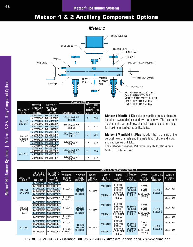
48C
usto
m H
ot
Ru
nn
er
Syste
ms |
In
dex
U.S. 800-626-6653 Canada 800-387-6600 [email protected] www.dme.net
Ho
t R
un
ner
Syste
ms |
In
dex
Meteor 1 & 2 Ancillary Component Options
WIRING KIT
CENTERSUPPORTPAD
DOWELPIN
HOT RUNNER NOZZLES THATCAN BE USED WITH THEMETEOR 1 AND METEOR 2 KITS:
DOWEL PIN
THERMOCOUPLE
METEOR 1 MANIFOLD KIT
L.H.C.S.
RISER PAD
DROOL RING
TOP
BOTTOM
NOZZLE SEAT
LOCATING RING
Meteor 1 Manifold Kit includes manifold, tubular heaters installed, two end plugs, and two set screws. The customer machines the vertical flow channel locations and end plugs for maximum configuration flexibility.
Meteor 2 Manifold Kit Plus includes the machining of the vertical flow channels and the installation of the end plugs and set screws by DME. The customer provides DME with the gate locations on a Meteor 2 Criteria Form.
Meteor 2
MANIFOLD TYPE
METEOR 1 MANIFOLD
KITITEM NO.
METEOR 2 MANIFOLD KIT PLUS ITEM NO.
DESIGN CRITERIA
NOZZLE OPTIONS
V VERTICAL FLOW
CHANNEL DIA.MM INCH
IN-LINEEND EXIT
MEM0100K MEM0100KP 250, EHA & CIASERIES 9 .354MEM0150K MEM0150KP
MEM0200K MEM0200KPMEM0300K MEM0300KP 375, EHA & CIA
SERIES 12 .472MEM0400K MEM0400KPMEM0500K MEM0500KP
IN-LINECENTER
EXIT
MCM0100K MCM0100KP 250, EHA & CIASERIES 9 .354MCM0150K MCM0150KP
MCM0200K MCM0200KPMCM0300K MCM0300KP 375, EHA & CIA
SERIES 12 .472MCM0400K MCM0400KPMCM0500K MCM0500KP
X-STYLE
MXM0100K MXM0100KP 250, EHA & CIASERIES 9 .354MXM0150K MXM0150KP
MXM0200K MXM0200KP
MXM0300K MXM0300KP 375, EHA & CIASERIES 12 .472
MANIFOLD TYPE
METEOR 1 MANIFOLD
KITITEM NO.
METEOR 2 MANIFOLD KIT PLUS ITEM NO.
ANCILLARY COMPONENT OPTIONS
THERMO-COUPLE
ITEM NO.
LOCATING RING
ITEM NO.
DROOL RING
ITEM NO.
NOZZLE SEAT
ITEM NO.
RISER PADS
ITEM NO.
CTR. SUPPORT
PADS ITEM NO.
DOWEL PINS
ITEM NO.
1/4-20 X .50 LG. L.H.C.S. ITEM NO.
WIRING KIT ITEM
NO.
IN-LINEEND EXIT
MEM0100K MEM0100KP
ETC0252 EHL0253EHL0255
(1 REQ’D.)EHL1003
MNS0009 ERP1001ERP1002ERP1011ERP1012
(2 OF SAME REQ’D.)
ECB0468ECB0469ECB0503
(1 REQ’D.)
DP820DP828DP832
(2 OF SAME REQ’D.)
1412LH(2 REQ’D.)
MWK1001MEM0150K MEM0150KPMEM0200K MEM0200KPMEM0300K MEM0300KP
MNS0012MEM0400K MEM0400KP
MEM0500K MEM0500KP ETC0252(2 REQ’D.) MWK1002
IN-LINECENTER
EXIT
MCM0100K MCM0100KP
ETC0252 EHL0253EHL0255
(1 REQ’D.)EHL1003
MNS0009 ERP1001ERP1002ERP1011ERP1012
(2 OF SAME REQ’D.)
ECB0468ECB0469ECB0503
(1 REQ’D.)
DP820DP828DP832
(2 OF SAME REQ’D.)
1412LH(2 REQ’D.)
MWK1001MCM0150K MCM0150KPMCM0200K MCM0200KPMCM0300K MCM0300KP
MNS0012MCM0400K MCM0400KP
MCM0500K MCM0500KP ETC0252(2 REQ’D.) MWK1002
X-STYLE
MXM0100K MXM0100KP ETC0252EHL0253EHL0255
(1 REQ’D.)EHL1003
MNS0009ERP1001ERP1002ERP1011ERP1012
(4 OF SAME REQ’D.)
ECB0468ECB0469ECB0503
(1 REQ’D.)
DP820DP828DP832
(2 OF SAME REQ’D.)
1412LH(2 REQ’D.)
MWK1001MXM0150K MXM0150KPMXM0200K MXM0200KP
ETC0252(2 REQ’D.) MWK1002MXM0300K MXM0300KP MNS0012
Mete
or®
Ho
t R
un
ner
Syste
ms |
M
eteo
r 1 &
2 A
ncill
ary
Com
pone
nt O
ptio
nsMeteor® Hot Runner Systems
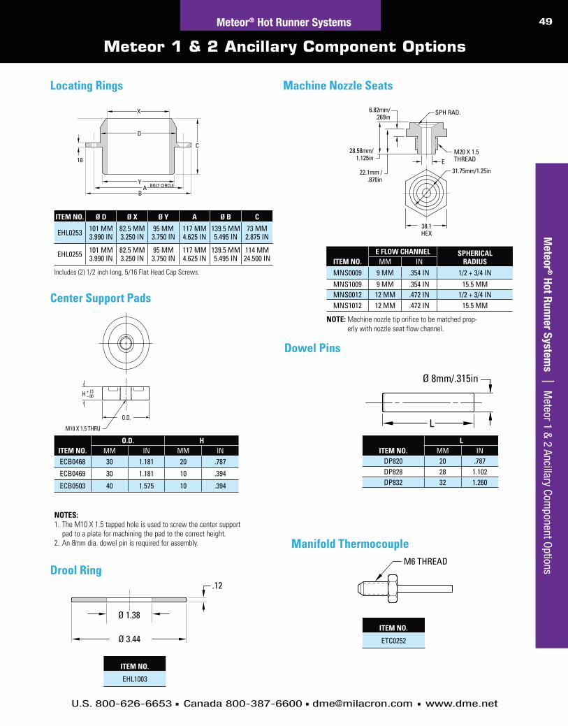
49C
usto
m H
ot R
un
ner S
yste
ms | N
ew Products
U.S. 800-626-6653 Canada 800-387-6600 [email protected] www.dme.net
Meteor 1 & 2 Ancillary Component Options
M20 X 1.5THREAD
SPH RAD.
31.75mm/1.25in
6.82mm/.269in
28.58mm/1.125in
22.1mm /.870in
E
38.1HEX
O.D.
M10 X 1.5 THRU
H +.13–.00
Locating Rings
X
D
C
AB
Y
18
BOLT CIRCLE
Center Support Pads
Machine Nozzle Seats
NOTE: Machine nozzle tip orifice to be matched prop-erly with nozzle seat flow channel.
ITEM NO.E FLOW CHANNEL SPHERICAL
RADIUSMM INMNS0009 9 MM .354 IN 1/2 + 3/4 INMNS1009 9 MM .354 IN 15.5 MMMNS0012 12 MM .472 IN 1/2 + 3/4 INMNS1012 12 MM .472 IN 15.5 MM
NOTES: 1. The M10 X 1.5 tapped hole is used to screw the center support
pad to a plate for machining the pad to the correct height.2. An 8mm dia. dowel pin is required for assembly.
ITEM NO.O.D. H
MM IN MM INECB0468 30 1.181 20 .787
ECB0469 30 1.181 10 .394
ECB0503 40 1.575 10 .394
Includes (2) 1/2 inch long, 5/16 Flat Head Cap Screws.
ITEM NO. Ø D Ø X Ø Y A Ø B C
EHL0253 101 MM3.990 IN
82.5 MM3.250 IN
95 MM3.750 IN
117 MM4.625 IN
139.5 MM5.495 IN
73 MM2.875 IN
EHL0255 101 MM3.990 IN
82.5 MM3.250 IN
95 MM3.750 IN
117 MM4.625 IN
139.5 MM5.495 IN
114 MM24.500 IN
Mete
or
® H
ot R
un
ner S
yste
ms | M
eteor 1 & 2 Ancillary Com
ponent Options
Meteor® Hot Runner Systems
Dowel Pins
Ø 8mm/.315in
L
ITEM NO.L
MM INDP820 20 .787DP828 28 1.102DP832 32 1.260
Drool Ring.12
Ø 1.38
Ø 3.44
ITEM NO.
EHL1003
Manifold ThermocoupleM6 THREAD
ITEM NO.
ETC0252
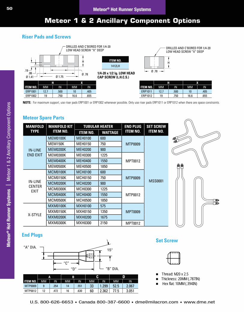
50C
usto
m H
ot
Ru
nn
er
Syste
ms |
In
dex
U.S. 800-626-6653 Canada 800-387-6600 [email protected] www.dme.net
Ho
t R
un
ner
Syste
ms |
In
dex
Mete
or®
Ho
t R
un
ner
Syste
ms |
M
eteo
r 1 &
2 A
ncill
ary
Com
pone
nt O
ptio
ns
Meteor 1 & 2 Ancillary Component Options
1/4-20 x 1/2 lg. LOW HEAD CAP SCREW (L.H.C.S.)
NOTE: For maximum support, use riser pads ERP1001 or ERP1002 whenever possible. Only use riser pads ERP1011 or ERP1012 when there are space constraints.
.06.19
H
Ø .78Ø 1.75Ø 1.41
DRILLED AND C’BORED FOR 1/4-20LOW HEAD SCREW “X” DEEP
DRILLED AND C’BORED FOR 1/4-20LOW HEAD SCREW “X” DEEP
H
Ø .78
Riser Pads and Screws
ITEM NO.H X
MM IN MM INERP1011 12.7 .500 10 .405ERP1012 19 .750 16.6 .655
ITEM NO.H X
MM IN MM INERP1001 12.7 .500 10 .405ERP1002 19 .750 16.6 .655
Meteor® Hot Runner Systems
ITEM NO.
1412LH
MANIFOLD TYPE
MANIFOLD KIT ITEM NO.
TUBULAR HEATER END PLUG ITEM NO.
SET SCREW ITEM NO.ITEM NO. WATTAGE
IN-LINE END EXIT
MEM0100K MEH0100 600MTP0009
MSS0001
MEM150K MEH0150 750MEM0200K MEH0200 900MEM0300K MEH0300 1225
MPT0012MEM0400K MEH0400 1550MEM0500K MEH0500 1850
IN-LINE CENTER
EXIT
MCM0100K MCH0100 600MTP0009MCM0150K MCH0150 750
MCM0200K MCH0200 900MCM0300K MCH0300 1225
MTP0012MCM0400K MCH0400 1550MCM0500K MCH0500 1850
X-STYLE
MXM0100K MXH0100 575MPT0009MXM0150K MXH0150 1350
MXM0200K MXH0200 1675MXM0300K MXH0300 2150 MPT0012
“D”“C”
“B” DIA.
“A” DIA.
End PlugsSet Screw
ITEM NO.A B C D
MM IN MM IN MM IN MM INMTP0009 9 .354 14 .551 33 1.299 52.5 2.067MTP0012 12 .472 16 .630 60 2.362 77.5 3.051
Thread: M20 x 2.5Thickness: 20MM (.787IN) Hex flat: 10MM (.394IN)
Meteor Spare Parts

DME Hot Sprue Bushings

U.S. 800-626-6653 Canada 800-387-6600 [email protected] www.milacron.com
Go to www.dme.net/prices for the latest pricing guide.Online Price Guide
Table of Contents
52 Hot Sprue Bushings
D-MAX High Performance Hot Sprue Bushings .......... 53-59Capability with engineered and commodity-grade resins
Straight-Shot™ Hot Sprue Bushings ......................... 68-78Reduce cycle times and save material costs
Integrally Heated Hot Sprue Bushings.....................79-84Advanced heat transfer capability promotes a more uniform heat profile
Gate-Mate® Hot Sprue Bushings .............................. 60-67Ideal for direct part gating, single-cavity molds
Hot Runner Services....................................................85-90Total support for your hot runner systems
Obsolete Replacement Parts ..................................91-101Obsolete replacement parts for hot runner systems
and nozzles

D-M
AX
Hig
h P
erfo
rma
nce H
ot S
pru
e B
ush
ing
s
D-MAX High Performance Hot Sprue Bushings
HIGH-PERFORMANCE CAPABILITY
WITH ENGINEERED AND
COMMODITY-GRADE RESINS
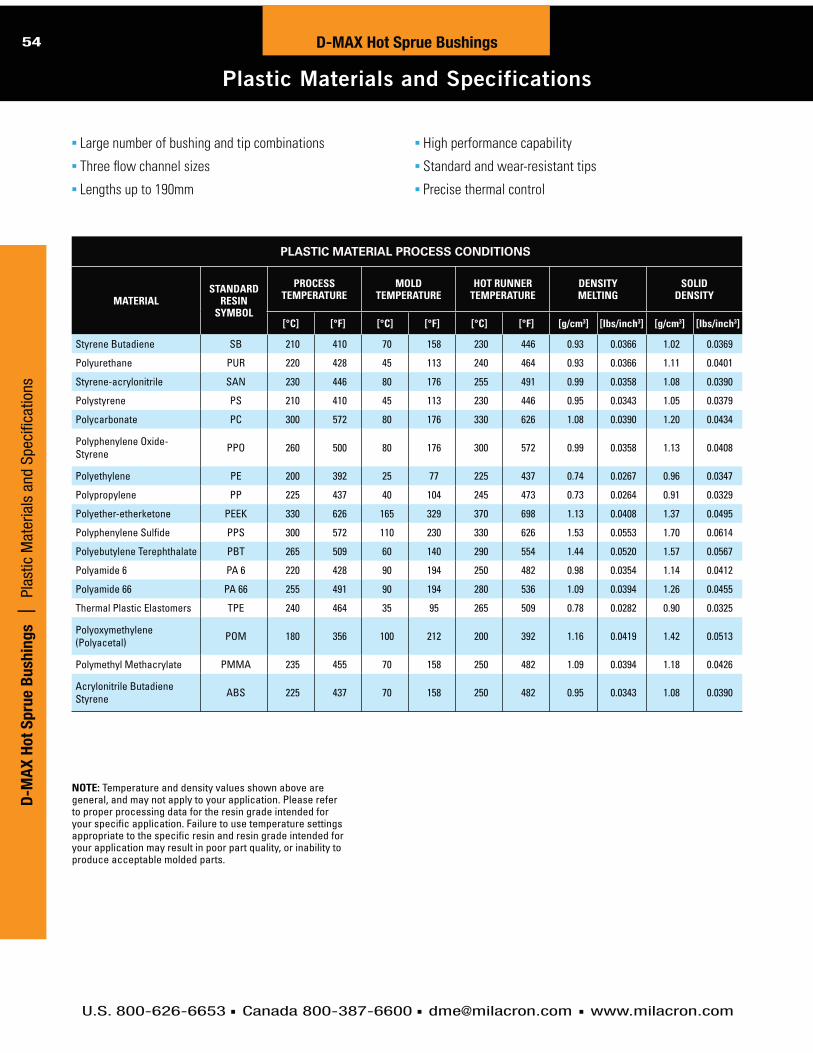
U.S. 800-626-6653 Canada 800-387-6600 [email protected] www.milacron.com
54 D-MAX Hot Sprue Bushings
Plastic Materials and Specifications
D-M
AX
Ho
t S
pru
e B
ush
ing
s |
Pl
astic
Mat
eria
ls a
nd S
peci
ficat
ions
PLASTIC MATERIAL PROCESS CONDITIONS
MATERIAL STANDARD
RESIN SYMBOL
PROCESS TEMPERATURE
MOLD TEMPERATURE
HOT RUNNER TEMPERATURE
DENSITY MELTING
SOLID DENSITY
[°C] [°F] [°C] [°F] [°C] [°F] [g/cm3] [Ibs/inch3] [g/cm3] [Ibs/inch3]
Styrene Butadiene SB 210 410 70 158 230 446 0.93 0.0366 1.02 0.0369
Polyurethane PUR 220 428 45 113 240 464 0.93 0.0366 1.11 0.0401
Styrene-acrylonitrile SAN 230 446 80 176 255 491 0.99 0.0358 1.08 0.0390
Polystyrene PS 210 410 45 113 230 446 0.95 0.0343 1.05 0.0379
Polycarbonate PC 300 572 80 176 330 626 1.08 0.0390 1.20 0.0434
Polyphenylene Oxide-Styrene PPO 260 500 80 176 300 572 0.99 0.0358 1.13 0.0408
Polyethylene PE 200 392 25 77 225 437 0.74 0.0267 0.96 0.0347
Polypropylene PP 225 437 40 104 245 473 0.73 0.0264 0.91 0.0329
Polyether-etherketone PEEK 330 626 165 329 370 698 1.13 0.0408 1.37 0.0495
Polyphenylene Sulfide PPS 300 572 110 230 330 626 1.53 0.0553 1.70 0.0614
Polyebutylene Terephthalate PBT 265 509 60 140 290 554 1.44 0.0520 1.57 0.0567
Polyamide 6 PA 6 220 428 90 194 250 482 0.98 0.0354 1.14 0.0412
Polyamide 66 PA 66 255 491 90 194 280 536 1.09 0.0394 1.26 0.0455
Thermal Plastic Elastomers TPE 240 464 35 95 265 509 0.78 0.0282 0.90 0.0325
Polyoxymethylene (Polyacetal) POM 180 356 100 212 200 392 1.16 0.0419 1.42 0.0513
Polymethyl Methacrylate PMMA 235 455 70 158 250 482 1.09 0.0394 1.18 0.0426
Acrylonitrile Butadiene Styrene ABS 225 437 70 158 250 482 0.95 0.0343 1.08 0.0390
NOTE: Temperature and density values shown above are general, and may not apply to your application. Please refer to proper processing data for the resin grade intended for your specific application. Failure to use temperature settings appropriate to the specific resin and resin grade intended for your application may result in poor part quality, or inability to produce acceptable molded parts.
Large number of bushing and tip combinations
Three flow channel sizes
Lengths up to 190mm
High performance capability
Standard and wear-resistant tips
Precise thermal control

U.S. 800-626-6653 Canada 800-387-6600 [email protected] www.milacron.com
55
R0.125ØO
Ø0.3750 0.0000+0.0005
30°
Ø1.187 MIN
.005
LAN
D M
AX0.
020
AT
TAN
G.0.
100
0.18
0
80° Ø1.187 MIN
30°
0.08
0 M
IN.ØS 0.0000
+0.0005
30°
Ø1.187 MIN
ØS 0.0000+0.0005
Ø1.187 MIN30°
25° MAX
ØS 0.0000+0.0005
0.08
0 M
IN.
0.08
0 M
IN.R0.010-0.015
CUSTOMER RADIUS TOSUIT
“O” DIA.“S” DIA.
UNFILLED RESIN FILLED RESIN
0.028 Min. 0.062 Min.
*0.3750
0.5005
0.7505
1.0005
D-MAX Hot Sprue BushingsD
-MA
X H
ot S
pru
e B
ush
ing
s | D
-MAX High Perform
ance Series 250
High Performance Hot Sprue Bushing 250 Series
BUSHING AND COMPONENT SPECIFICATIONS
ASSEMBLY “A” DIMENSION
ASSEMBLY COMPONENTSBUSHING BODY
DETAIL #1HIGH PERFORMANCE
HEATER DETAIL #2 WATTAGE HEAD HEATER DETAIL #3 WATTAGE THERMOCOUPLE
DETAIL #4DMAX06055 2.165in (55.00mm) DEP06055 CIH0081S 440
RDP38021 500 DTC38001
DMAX06067 2.657in (67.50mm) DEP06067 CIH0082S 350DMAX06080 3.150in (80.00mm) DEP06080 CIH0083S 400DMAX06092 3.642in (92.50mm) DEP06092 CIH0084S 565DMAX06105 4.134in (105.00mm) DEP06105 CIH0085S 500DMAX06130 5.118in (130.00mm) DEP06130 CIH0086S 500DMAX06155 6.102in (155.00mm) DEP06155 CIH0087S 550
POINT GATE (BODILESS)
NOTE: Dimensions shown in inches unless specified otherwise. For selection of gate diameter it is important to take into consideration the material flow characteristics, share rate of resin, molding conditions, fill time requirements, gate vestige, wall thickness and configuration of parts to be molded. Situations requiring high injection velocities must be considered when selecting small gate diameters. High injection rates may require larger gates due to shear heat build up (e.g. high weight thin wall applications). See material manufacturer’s literature for further information regarding material to be molded.
To compensate for nozzle’s growth when heat is applied, the linear expansion of the nozzle (BE) at a given temperature must be added to the nominal “A” dimension. The formula below shows how to figure boring depth (dimension “A” + BE). The tip of the nozzle will now be flush with the cavity line at processing temperature.
Formula for determining this expansion factor is as follows:BE = “A” dimension x 0.00000633 x nozzle set point - 68ºF (assuming the mold is at 68ºF during operation). If mold temperature is different, substitute 68ºF with actual mold temperature.
EXAMPLE: Given a 4.134 inch “A” dimension, with a set point of 500ºF:
BE = 4.134 x 0.00000633 x (500 - 68) = 0.011Thus “A” + BE will be 4.145
NOTE: The above information is only given as an example; variations may occur based on mold configurations and cooling factor. In some instances, it may be necessary to obtain an empirical factor.
STD. SPRUE AND POINT GATE (FULL BODY)
EXTENDED SPRUE AND EXTENDED POINT GATE
(FULL BODY) RUNNER DESIGN
EXTENDED SPRUE AND EXTENDED POINT GATE
(FULL BODY) ANGLE DESIGN
* Point Gate (Full Body) only.
Ø0.31R0.50
R0.75
0.16
.50
MIN
A + BE
R0.016 MAX
0.22
Min
. - .5
5 M
ax.
1.29
90.
000
+0.0
01
0.12Ø1.187 Min. -
Ø1.250 Max.
0.31 MIN
NOTE: MATCH MACHINENOZZLE TIP ORIFICE
INSULATION SHEET(OPTIONAL)
WATER LINES 1/2-24 UNTORQUE TO 30 FT/LBS
12
5
3
4
Ø4.000 LOCATING RING BORE 1.
57CE
NTR
AL
R0.38
Ø2.165 HEAD HEATER BORE
Ø1.575 + 0.0010.000 Head Bore
0.717 + 0.0010.000
R0.24
1.6
56
1.50
0.7
5
0.3
3
0.3
3
3.50
0.49 (2) 5/16-18 UNC Tap
* Locating
rings must
be ordered
separately.

U.S. 800-626-6653 Canada 800-387-6600 [email protected] www.milacron.com
56 D-MAX Hot Sprue Bushings
High Performance Hot Sprue Bushing 375 Series
D-M
AX
Ho
t S
pru
e B
ush
ing
s |
D
-MAX
Hig
h Pe
rfor
man
ce S
erie
s 37
5
BUSHING AND COMPONENT SPECIFICATIONS
ASSEMBLY “A” DIMENSION
ASSEMBLY COMPONENTSBUSHING BODY
DETAIL #1HIGH PERFORMANCE
HEATER DETAIL #2 WATTAGE HEAD HEATER DETAIL #3 WATTAGE THERMOCOUPLE
DETAIL #4DMAX10060 2.362in (60.00mm) DEP10060 CIH0088S 400
RDP50021 750 DTC38001
DMAX10072 2.854in (72.50mm) DEP10072 CIH0089S 450DMAX10085 3.346in (85.00mm) DEP10085 CIH0090S 550DMAX10097 3.839in (97.50mm) DEP10097 CIH0091S 700DMAX10110 4.331in (110.00mm) DEP10110 CIH0092S 800DMAX10135 5.315in (135.00mm) DEP10135 CIH0093S 900DMAX10160 6.299in (160.00mm) DEP10160 CIH0094S 1000DMAX10185 7.283in (185.00mm) DEP10185 CIH0095S 1100
NOTE: Dimensions shown in inches unless specified otherwise. For selection of gate diameter it is important to take into consideration the material flow characteristics, share rate of resin, molding conditions, fill time requirements, gate vestige, wall thickness and configuration of parts to be molded. Situations requiring high injection velocities must be considered when selecting small gate diameters. High injection rates may require larger gates due to shear heat build up (e.g. high weight thin wall applications). See material manufacturer’s literature for further information regarding material to be molded.
To compensate for nozzle’s growth when heat is applied, the linear expansion of the nozzle (BE) at a given temperature must be added to the nominal “A” dimension. The formula below shows how to figure boring depth (dimension “A” + BE). The tip of the nozzle will now be flush with the cavity line at processing temperature.
Formula for determining this expansion factor is as follows:BE = “A” dimension x 0.00000633 x nozzle set point - 68ºF (assuming the mold is at 68ºF during operation). If mold temperature is different, substitute 68ºF with actual mold temperature.
EXAMPLE: Given a 2.362 inch “A” dimension, with a set point of 500ºF:
BE = 2.362 x 0.00000633 x (500 - 68) = 0.0064Thus “A” + BE will be 2.368
NOTE: The above information is only given as an example; variations may occur based on mold configurations and cooling factor. In some instances, it may be necessary to obtain an empirical factor.
“O” DIA. “S” DIA.UNFILLED RESIN FILLED RESIN
0.028 Min. 0.062 Min.0.50050.75051.0005
POINT GATE (BODILESS)
EXTENDED SPRUE AND EXTENDED POINT GATE
(FULL BODY) RUNNER DESIGN
EXTENDED SPRUE AND EXTENDED POINT GATE
(FULL BODY) ANGLE DESIGN
R0.187ØO
Ø0.5000 0.0000+0.0005
30°
Ø1.437 MIN
0.00
5 L
AND
MAX
0.02
0 A
T TA
NG.
0.10
00.
180
80° Ø1.437 MIN
30°
0.08
0 M
IN.
0.0000+0.0005
30°
Ø1.437 MIN
0.0000+0.0005
Ø1.437 MIN30°
25° MAX
0.0000+0.0005
0.08
0 M
IN.
0.08
0 M
IN.R0.010-0.015
CUSTOMER RADIUS TOSUIT
ØS
ØS ØS
Ø0.47 R0.50R0.75
0.16
0.50
MIN
R0.016 MAX
0.22
Min
. - .5
5 M
ax.
1.29
90.
000
+0.0
01
0.12Ø1.437 Min. -
Ø1.625 Max.
0.31 MIN
NOTE: MATCH MACHINENOZZLE TIP ORIFICE
INSULATION SHEET(OPTIONAL)
WATER LINES 5/8-20 UNTORQUE TO 30 FT/LBS
1
2
3
5
4
Ø4.000 LOCATING RING BORE
1.77 1.
57CE
NTR
AL
R0.38
Ø2.913 HEAD HEATER BORE
1.6
56
0.933 + 0.0040.000
Head Bore Ø2.008 + 0.0010.000
R0.25
0.3
7
0.3
7
0.71
3.50
0.7
5
(2) 5/16-18 UNC Tap
A + BE
* Locating
rings must
be ordered
separately.
STD. SPRUE AND POINT GATE (FULL BODY)

U.S. 800-626-6653 Canada 800-387-6600 [email protected] www.milacron.com
57D-MAX Hot Sprue Bushings
High Performance Hot Sprue Bushing 625 Series
D-M
AX
Ho
t Sp
rue B
ush
ing
s | High Perform
ance Hot Sprue Bushing 625 Series
POINT GATE (BODILESS)
STD. SPRUE AND POINT GATE (FULL BODY)
EXTENDED SPRUE RUNNER DESIGN EXTENDED SPRUE AND
ANGLE DESIGN
30°
25° MAX.
0.08
MIN
.
30°
Ø2.125 MIN
0.08
MIN
.
30°
ØS
0.08
MIN
.
CUSTOMER RADIUS TOSUIT
+.0005-.0000
ØS
Ø2.125 MIN Ø2.125 MIN
ØS
+.0005-.0000 +.0005
-.0000
Ø2.125 MIN80°
30°
0.00
5 L
AND
MAX
0.02
0 A
T TA
NG.
0.12
50.
235
Ø0.6250 0.0000+0.0005
0.4
7
R0.312
R0.010-0.015
R0.125
ØO
NOTE: Dimensions shown in inches unless specified otherwise.
BUSHING AND COMPONENT SPECIFICATIONS
ASSEMBLY “A” DIMENSION
ASSEMBLY COMPONENTSBUSHING BODY
DETAIL #1BUSHING HEAD
DETAIL #2CAST-IN HEATER
DETAIL #3 WATTAGE HEAD HEATER DETAIL #4 WATTAGE THERMOCOUPLE
DETAIL #5DMAX16090 3.543in (90.00mm) DEP16090
DBP16001
CIH0104-S 847
RDP38021 500 DTC62501
DMAX16115 4.528in (115.00mm) DEP16115 CIH0096-S 1000DMAX16140 5.512in (140.00mm) DEP16140 CIH0097-S 1030DMAX16165 6.496in (165.00mm) DEP16165 CIH0098-S 1100DMAX16190 7.480in (190.00mm) DEP16190 CIH0099-S 1000DMAX16215 8.465in (215.00mm) DEP16215 CIH0101-S 1200DMAX16240 9.449in (240.00mm) DEP16240 CIH0102-S 1200DMAX16265 10.433in (265.00mm) DEP16265 CIH0103-S 1200
For selection of gate diameter it is important to take into consideration the material flow characteristics, shear rate of resin, molding conditions, fill time requirements, gate vestige, wall thickness and configuration of parts to be molded. Situations requiring high injection velocities must be considered when selecting small gate diameters. High injection rates may require larger gates due to shear heat build up (e.g. high weight thin wall applications). See material manufacturer’s literature for further information regarding material to be molded.
To compensate for nozzle’s growth when heat is applied, the linear expansion of the nozzle (BE) at a given temperature must be added to the nominal “A” dimension. The formula below shows how to figure boring depth (dimension “A” + BE). The tip of the nozzle will now be flush with the cavity line at processing temperature.
Formula for determining this expansion factor is as follows:BE = “A” dimension x 0.00000633 x nozzle set point - 68ºF (assuming the mold is at 68ºF during operation). If mold temperature is different, substitute 68ºF with actual mold temperature.
EXAMPLE: Given a 3.543in “A” dimension, with a set point of 500ºF and mold temperature 68ºF:
BE = 3.543 x 0.00000633 x (500 - 68) = .010Thus “A” + BE will be 3.553
NOTE: The above information is only given as an example; variations may occur based on mold configurations and cooling factor. In some instances, it may be necessary to obtain an empirical factor.
Ø0.625
R 0.750
0.46
9-0
.001
0.00
0
0.37
5
0.06
X 4
5˚
0.06
X 4
5˚
0.06
X 4
5˚
Ø2.756 0.000+0.001
HEAD BOREØ4.000 LOCATING RING BORE
1.174
1.378
1.174
Ø8.00 DWL(OPTIONAL FORANTI-ROTATION)
3.50
0.75
1.74
3
0.6
33 M
in. -
1.2
83 M
ax.
0.31 MIN.
MIN. WIRE CHANNEL
Ø8 X18LG DWL(OPTIONAL FOR ANTI-ROTATION)
INSULATION SHEET(OPTIONAL)
1"-16 UNTORQUE TO 30 FT/LBS
NOTE: MATCH MACHINENOZZLE TIP ORIFICE
R0.030
1
2
3
4
5
6
(4) 5/16-18 UNC
WATER LINES
BUSHING HEATER CABLE EXIT
A + BE
2.125 MIN.
Ø2.125 HEATER BORE
HEAD
C’B
ORE
“O” DIA.“S” DIA.
UNFILLED RESIN FILLED RESIN
0.080 Min. 0.100 Min. 1.0005
* Locating
rings must
be ordered
separately.

U.S. 800-626-6653 Canada 800-387-6600 [email protected] www.milacron.com
58
Ø2.03
ØT 5° PER SIDE
C
A
RETAINER TIP
NEEDLE
L
ØT
A
D-MAX Hot Sprue Bushings
Gate Tip Detail
D-M
AX
Ho
t S
pru
e B
ush
ing
s |
Ga
te T
ip D
etai
l
E
5° PER SIDE
0.750
RETAINER TIP
NEEDLE
A
ØT ØO
E
RETAINER TIP
NEEDLE
A
ØO
ØT
SERIES GATE TIP ITEM NUMBER B DIA. T DIA. L C
250
SPRUE GATEEHT0010
.080
.500 .250 .375EHT0011 .750EHT0012 1.000 .100
1.125EXTENDED SPRUE GATEEHT0013 .500 1.000EHT0014 .750EHT0015 1.000 .850
375
SPRUE GATEEHT0016
.125
.500.250 .375EHT0017 .750
EHT0018 1.000
EXTENDED SPRUE GATEEHT0019 .500
1.000 1.125EHT0020 .750EHT0021 1.000
625 SPRUE GATE EHT0022 .187 1.000 .250 .500 EXTENDED SPRUE GATE EHT0023 1.000 1.250
SERIES GATE TIP ITEM NUMBER T DIA.INCLUDES
NEEDLE RETAINER TIP
250STANDARD EHT0005
.375EHN0015 EHT0024
EHT1314 EHT0324
WEAR RESISTANT EHT1308 EHN0401 EHT0324 EHT1313 EHT1324
375STANDARD EHT0039
.500EHN0016 EHT0025
EHT1312 EHT0325
WEAR RESISTANT EHT1303 EHN0400 EHT0325 EHT1309 EHT1325
625STANDARD EHT1306
.625EHN0019 EHT1354
EHT1311 EHT0326
WEAR RESISTANT EHT1307 EHN0402 EHT0326 EHT1310 EHT1354
Point Gate (Bodiless)
(Add .750 to A dimension for extended sprue gate tips.)
SERIES TYPE ITEM NUMBER T DIA. O DIA. EINCLUDES
NEEDLE RETAINER TIP
250
STANDARD
EHT2001 .375 .060
.187
EHN0015
EHT0026 EHT2002 .080 EHT0027 EHT2003 .500 .060 EHT0028 EHT2004 .080 EHT0029
WEAR RESISTANT
EHT2005 .375 .060
EHN0401
EHT1326 EHT2006 .080 EHT1327 EHT2007 .500 .060 EHT1328 EHT2008 .080 EHT1329
375
STANDARD
EHT2009 .500 .080
.230
EHN0016
EHT0030 EHT2010 .100 EHT0031 EHT2011 .750 .080 EHT0032 EHT2012 .100 EHT0033 EHT2013 1.000 .080 EHT0034 EHT2014 .100 EHT0035
WEAR RESISTANT
EHT2015 .500 .080
EHN0400
EHT1330 EHT2016 .100 EHT1331 EHT2017 .750 .080 EHT1332 EHT2018 .100 EHT1333 EHT2019 1.000 .080 EHT1334 EHT2020 .100 EHT1335
625 STANDARD EHT2021 1.000 .125 .250 EHN0019 EHT0036WEAR RESISTANT EHT2022 EHN0402 EHT1336
Point Gate (Full Body)
SERIES TYPE ITEM NUMBER T DIA. O DIA. EINCLUDES
NEEDLE RETAINER TIP
250
STANDARD
EHT2301 .375 .060
.938
EHN0015
EHT2326 EHT2302 .080 EHT2327 EHT2303 .500 .060 EHT2328 EHT2304 .080 EHT2329
WEAR RESISTANT
EHT2305 .375 .060
EHN0401
EHT2326 EHT2306 .080 EHT2327 EHT2307 .500 .060 EHT2328 EHT2308 .080 EHT2329
375
STANDARD
EHT2309 .500 .080
.980
EHN0016
EHT2330 EHT2310 .100 EHT2331 EHT2311 .750 .080 EHT2332 EHT2312 .100 EHT2333 EHT2313 1.000 .080 EHT2334 EHT2314 .100 EHT2335
WEAR RESISTANT
EHT2315 .500 .080
EHN0400
EHT2330 EHT2316 .100 EHT2331 EHT2317 .750 .080 EHT2332 EHT2318 .100 EHT2333 EHT2319 1.000 .080 EHT2334 EHT2320 .100 EHT2335
625 STANDARD EHT2321 1.000 .125 1.000 EHN0019 EHT2336WEAR RESISTANT EHT2322 EHN0402
Point Gate (Full Body Extended)
SERIES THREAD TYPE250 1/2-24 UN375 5/8-20 UN625 1"-16 UN
Sprue Gate/Extended Sprue Gate

U.S. 800-626-6653 Canada 800-387-6600 [email protected] www.milacron.com
59D
-MA
X H
ot S
pru
e B
ush
ing
s | 250, 375 &
625 Series Locating RingsD-MAX Hot Sprue Bushings
250, 375 & 625 Series Locating Rings
ITEM NUMBER Ø D
DMAXLR1034 34.00 (1.34")
DMAXLR1046 46.00 (1.81")
DMAXLR1063 63.00 (2.48")
NOTE: Dimensions shown in millimeters, inches in parentheses
5/16-18 TAPPED THRU (2)DRILLED AND C’BOREDFOR 5/16 DIA. SOCKETHEAD CAP SCREW (4)
5/16-18 TAPPED THRU (2)
DMAXLR1063DMAXLR1034 & DMAXLR1046
A
A
ØD
45°
Ø101.35 [3.990]
Ø38.2 [1.50]
SECTION A-A
DRILLED AND C’BOREDFOR 5/16 DIA. SOCKETHEAD CAP SCREW (2)
34.00 [1.339]
15.88 [0.625]
36.0 [1.42]
Ø84.12 [3.312]
Ø84.12 [3.312]
29.39 [1.157]
Ø101.35 [3.990]
9.9 [0.39]
44.28 [1.743]
32.00 [1.260]17.0 [0.67]
ØD
250, 375 & 625 Series Locating Rings

IDEAL FOR DIRECT
PART GATING,
SINGLE-CAVITY MOLDS
DME Gate-Mate® Hot Sprue Bushings

U.S. 800-626-6653 Canada 800-387-6600 [email protected] www.milacron.com
61Gate-Mate® Hot Sprue Bushings
Gate-Mate® Applications and Benefits
BODY
THERMOCOUPLE
SQUARECOIL HEATER
TIP
DME Gate-Mate® Hot Sprue BushingsThe DME Gate-Mate® Hot Sprue Bushing is designed for direct part gating in
single-cavity molds, eliminating the conventional cold sprue. The unique design
of the bushing provides minimal gate vestige, without the objectionable witness
lines so commonly found on direct gated parts.
The bushing transfers molten plastics from the machine nozzle to the mold
cavity via a direct channel in the body. The plated copper alloy tip provides
an improved temperature profile in the gate area.
The DME Gate-Mate® Hot Sprue Bushing utilizes an advanced design square coil
heater and independent thermocouple, strategically located for precise temperature
control. The bushing is available in three sizes to suit a variety of applications.
See the DME Control Systems Catalog for Smart Series® Single Zone Temperature Controllers.
TOP OFMOLD
LOCATIONRING
CAVITY
CORE
PART
Advantages Direct part gating eliminating a cold sprue to trim and no witness
lines on the molded part
Minimal gate vestige resulting in better part appearance
Faster start-ups providing positive temperature control of gate area
Reduced cycle times because the bushing allows cooling channels to be placed closer to the gate area
Cooler cavities with no direct contact between bushing tip and cavity
Improved part quality with a shorter injection path and elimination of sprue, meaning no regrind
Increased production with faster cycles and no sprue trimming
Easy installation and operation, and available in three standard sizes suitable for most applications
Positive temperature control with J-Type thermocouple and DME Smart-Series® (and G-Series) controllers
Mini and Jumbo Style Gate-Mate Bushings Shown
NOTE: Mini Gate-Mate is also available with a cast-in heater with integral thermocouple.
Typical Applications
Benefits Eliminates sprues, reduces cycle time, improves part quality, increases production
Provides optimum gate cosmetics
Plated copper alloy tip improves temperature profile in gate area
Self insulating material layer surrounds tip for better tip control and part cooling
Square coil heater and independent thermocouple provide precise temperature control
Optional cast in heater available for Mini Gate-Mate bushing
Ga
te-M
ate
® H
ot S
pru
e B
ush
ing
s | Gate-M
ate®
Applications and Benefits
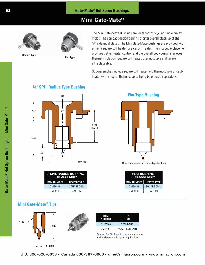
U.S. 800-626-6653 Canada 800-387-6600 [email protected] www.milacron.com
62
Mini Gate-Mate®
Gate-Mate® Hot Sprue Bushings
The Mini Gate-Mate Bushings are ideal for fast cycling single cavity
molds. The compact design permits shorter overall stack-up of the
“A” side mold plates. The Mini Gate-Mate Bushings are provided with
either a square coil heater or a cast-in heater. Thermocouple placement
provides better heater control, and the overall body design improves
thermal insulation. Square coil heater, thermocouple and tip are
all replaceable.
Sub-assemblies include square coil heater and thermocouple or cast-in
heater with integral thermocouple. Tip to be ordered separately.
1.086
-20
.010 DIA.
21
Mini Gate-Mate® Tips
1/2 SPH. RADIUS BUSHING SUB-ASSEMBLY
ITEM NUMBER HEATER TYPE
GMB0116 SQUARE COIL
GMB0111 CAST-IN
FLAT BUSHING SUB-ASSEMBLY
ITEM NUMBER HEATER TYPE
GMB0117 SQUARE COIL
GMB0112 CAST-IN
ITEM NUMBER
TIP STYLE
GMT0100 STANDARD
GMT4101 WEAR RESISTANT
Contact for DME for tip recommendations and assistance with your application.
1.500
.250.625
.281
.6250 DIA.
1.187HEATER
1.375
Dimensions same as radius type bushing
Flat Type Bushing
1⁄2" SPH. Radius Type Bushing
Radius TypeFlat Type
Ga
te-M
ate
® H
ot
Sp
rue B
ush
ing
s |
M
ini G
ate-
Mat
e®

U.S. 800-626-6653 Canada 800-387-6600 [email protected] www.milacron.com
63Gate-Mate® Hot Sprue Bushings
Mini Gate-Mate® Machining Dimensions
NOTE:The expansion factor must be taken into consideration prior to machining for and installation of the bushing. This factor (BE) must then be added to the A dimension. The formula for determining this expansion factor is as follows:
BE = “A” dimension x 0.00000633 x nozzle set point - 68ºF (assuming the mold is at 68ºF during operation). If mold temperature is different, substitute 68ºF with actual mold temperature.
EXAMPLE:Given a setpoint of 500°F: BE = 1.375 × .0000063 × (500 – 68) = .004 thus 1.375 + .004 = 1.379.Please note that the above information is given as an example. Variations may occur based on mold configuration and cooling factor. In some instances, it may be necessary to obtain an empirical factor.
SUB-ASSEMBLY REFERENCE
BODY TYPE
HEATER TYPE (240 VAC, 250 WATT)
THERMOCOUPLE (36" LEADS)
GMB0111 1⁄2 RADIUS (CAST IN)CIH0100
N/A(INTEGRAL TO HEATER)GMB0112 FLAT
GMB0116 1⁄2 RADIUS (SQUARE COIL)SCH0004 TCG0100
GMB0117 FLAT
ITEM NUMBER
6548
NOTES:1. Two (2) 5⁄16-18 S.H.C.S. are included with Locating Ring2. Two (2) Drilled and C’bored holes for 5⁄16-18 S.H.C.S. are
on a 1.656 circle radius in Locating Ring3. C’bore depth in Top Clamp Plate and C’bore depth in
Locating Ring can be altered to suit application
.31 MIN. DISTANCE BETWEEN WATERLINE AND DROP
+.0005–.0000
.6250 DIA.
.125 RAD.
.219 MIN.
.719 MAX.
.400
4.000 DIA.
+.001–.000
.125 RAD.
.125
.625 WIRE CHANNEL1.125 DIA.
.125 MIN.
.407 MAX.
1.501 DIA.
1.375 + BESEE NOTE
+.0005–.0000
.6250 DIA.
.125 RAD.
.187 SPH. RAD..005 LAND (MAX.)
.030.030 MIN.
.80˚INCL
118˚
Machining Dimensions for Bushings
Replacement Parts
3.990 DIA.1.50 DIA.
-18 TAPPED THRU
DRILLED & C'BORED FOR -18 S.H.C.S.
1.500
.218
165
16532
7
1.250
.53
2.375
Mini Gate-Mate Bushing Locating Ring
Ga
te-M
ate
® H
ot S
pru
e B
ush
ing
s | M
ini Gate-Mate
® Machining D
imensions

U.S. 800-626-6653 Canada 800-387-6600 [email protected] www.milacron.com
64
Medium Gate-Mate®
Gate-Mate® Hot Sprue Bushings
NOTES:1. Thru-hole tip is designed .040 shorter in length to be a direct
replacement for the standard tip; use a .030 to .060 diameter gate2. A .030 minimum diameter gate is recommended when using the
super sharp tip3. Contact DME for tip recommendations and assistance with
your application
A
L
2.156 DIA.
.024 DIA.7500 DIA.
.2501.062
.562
.730
A
L
2.156 DIA.
7500 DIA.
.2501.062
.562
.730
BUSHING ASSEMBLY (INCLUDES GMT2 TIP)
ITEMNUMBER A L DUAL
SPH. RAD.GMB5232 2.375 3.437
1/2 & 3/4GMB5332 3.375 4.437
BUSHING SUB-ASSEMBLY (ORDER TIP SEPARATELY)
ITEMNUMBER A L DUAL
SPH. RAD.GMB0020 2.375 3.437
1⁄2 & 3⁄4GMB0030 3.375 4.437
The Medium Gate-Mate Bushing is designed for direct part gating in single cavity molds,
eliminating the conventional cold sprue. The unique design of the bushing provides
minimal gate vestige, without the objectionable witness lines so commonly found
on direct gated parts.
The bushing transfers molten plastics from the machine nozzle to the mold cavity
via a direct channel in the body. The bushing, in conjunction with the recommended
tip and gate configuration, controls gate vestige height.
The Medium Gate-Mate Bushing utilizes an advanced design square coil heater and
an independent thermocouple, strategically located for precise temperature control.
TIP STYLE
TIP ITEM NUMBER
O DIA.
TIP LENGTH
TIP DIA.
HOLE DIA.
STANDARD GMT2 .044 MIN.
1.730
.024
N/A
WEAR RESISTANT GMT0400 .055 MIN.
SUPER SHARP GMT0301 .030 MIN.
.010SUPER SHARPWEAR RESISTANT GMT0401 .055 MIN.
THRU HOLE GMT0302* .030 MIN..050 MAX
1.690 .090 .050THRU HOLE
WEAR RESISTANT GMT0402* .055 MIN.
NO HOLE GMT0303 .044 MIN. 1.730 .024 N/A
Medium Gate-Mate® Tips
TIP DIA.
TYPICAL .125 DIA. HOLE
TIP DIA.
HOLE DIA.TIP DIA.
.11810˚ ˚0"
NO HOLE
MOLDMAKER TO MACHINE
THRU HOLETHRU HOLE WEAR RESISTANT
STANDARD WEAR RESISTANT
SUPER SHARPSUPER SHARP WEAR RESISTANT
TIPLENGTH
-20(typ.)2
1
Bushing Assembly Bushing Sub-Assembly
*Contact DME for details to modify thru-hole tips for larger “O” diameters.
Ga
te-M
ate
® H
ot
Sp
rue B
ush
ing
s |
M
ediu
m G
ate-
Mat
e®

U.S. 800-626-6653 Canada 800-387-6600 [email protected] www.milacron.com
65Gate-Mate® Hot Sprue Bushings
Medium Gate-Mate® Machining Dimensions
NOTE:The expansion factor must be taken into consideration prior to machining for, and installing bushing. This factor (BE) must then be added to the nominal A dimension. Formula for determining this expansion is as follows: BE = “A” dimension x 0.00000633 x nozzle set point - 68ºF (assuming the mold is at 68ºF during operation). If mold temperature is different, substitute 68ºF with actual mold temperature.
EXAMPLE:Given a 2.375 inch A dimension, with a Bushing Set Point temp. of 500°F: BE = 2.375 × .0000063 × (500 – 68) = .006 thus A + BE will be 2.381.Please note that the above information is given as an example. Variations may occur based on mold configurations and cooling factor. In some instances, it may be necessary to obtain an empirical factor.
ITEM NUMBER REFERENCE
SQUARE COIL HEATERS (240 VAC)
THERMOCOUPLE (TYPE J, 36" LEADS)
BUSHING ASSEMBLY
BUSHING SUB-ASSEMBLY
ITEM NUMBER WATTS LENGTH ITEM
NUMBER LENGTH
GMB5232 GMB0020 SCH3142 315 1.70 TC9600 1.35
GMB5332 GMB0030 SCH3242 315 2.70 TC9700 2.35
ITEM NUMBER
6545
NOTES:1. Two (2) 5⁄16 -18 S.H.C.S. are included with
Locating Ring2. Two (2) Drilled and C’bored holes for
5⁄16 -18 S.H.C.S. are on a 1.656 circle radius in Locating Ring
3. C’bore depth in Top Clamp Plate and C’bore depth in Locating Ring can be altered to suit application
Machining Dimensions for Bushings
Replacement Parts
Medium Gate-Mate Locating Ring
.31 MIN. DISTANCE BETWEEN WATERLINE AND DROP
+.0005–.0000
.7500 DIA..125 RAD.
.219.563
.875
4.000 DIA.
+.002–.000
.125 RAD.
.140
.625 WIRE CHANNEL
1.625 DIA.
2.187 DIA.
30˚
2.157 DIA.
A + BESEE NOTE
3.990 DIA.2.216 DIA.
-18 TAPPED THRU
DRILLED & C'BORED FOR -18 S.H.C.S.
1.781
.218
165
16532
7
1.250
.53
2.375
Improved tip insulation, elimination of material degradation in
threaded area of tip, and faster color changes can be achieved
through use of a Gate Shell Insulator.
+.0005–.0000
.7500 DIA.
.375 RAD.
.187 SPH. RAD..005 LAND (MAX.)
.030TO SUIT.044 MIN.
(.030 MIN. FORSUPER SHARP TIP)
.80˚INCL
90˚
ITEM NUMBER REFERENCE
ABUSHING
ASSEMBLYBUSHING
SUB-ASSEMBLY
GMB5232 GMB0020 2.375
GMB5332 GMB0030 3.375
Ga
te-M
ate
® H
ot S
pru
e B
ush
ing
s | M
edium Gate-M
ate® M
achining Dim
ensions

U.S. 800-626-6653 Canada 800-387-6600 [email protected] www.milacron.com
66 Gate-Mate® Hot Sprue Bushings
Jumbo Gate-Mate®
TIP DIA.
-16(typ.)
TIPLENGTH
TIP DIA.
HOLE DIA.
STANDARDWEAR RESISTANT
43
THRU HOLETHRU HOLE WEAR RESISTANT
NOTES:1. Thru-hole tip designed .040 shorter in length to be a
direct replacement for the standard tip; use a .080 to .125
diameter gate
2. Contact DME for tip recommendations and assistance with
your application
The Jumbo Gate-Mate Bushing is designed for direct part gating in single
cavity molds, eliminating the conventional cold sprue. The unique design of
the bushing provides minimal gate vestige, without the objectionable witness
lines so commonly found on direct gated parts.
The bushing transfers molten plastics from the machine nozzle to the mold
cavity via a direct channel in the body. The bushing, in conjunction with the
recommended tip and gate configuration, controls gate vestige height.
The Jumbo Gate-Mate Bushing utilizes an advanced design square coil
heater and an independent thermocouple, strategically located for precise
temperature control.
TIP STYLE
ITEM NUMBER
TIP LENGTH
TIP DIA.
HOLE DIA.
STANDARD GMT00041.855 .030 N/A
WEAR RESISTANT GMT0406
THRU HOLE GMT0007
1.815 .140 .100THRU HOLE WEAR RESISTANT GMT0407
Jumbo Gate-Mate® Tips
A
L
2.625 DIA.
.030 DIA.1.2500 DIA.
.5001.062
.562
.855
A
L
2.625 DIA.
1.2500 DIA.
.5001.062
.562
.855
Bushing Assembly Bushing Sub-Assembly
BUSHING ASSEMBLY (INCLUDES GMT0004 TIP)
ITEMNUMBER A L SPH. RAD.GMB0008 2.500 3.562
1/2 & 3/4GMB0009 3.500 4.562
BUSHING SUB-ASSEMBLY (ORDER TIP SEPARATELY)
ITEMNUMBER A L SPH. RAD.GMB0113 2.500 3.562
1/2 & 3/4GMB0114 3.500 4.562
Ga
te-M
ate
® H
ot
Sp
rue B
ush
ing
s |
Ju
mbo
Gat
e-M
ate®

U.S. 800-626-6653 Canada 800-387-6600 [email protected] www.milacron.com
67
Jumbo Gate-Mate® Machining Dimensions
Gate-Mate® Hot Sprue Bushings
NOTE:The expansion factor must be taken into consideration prior to machining for, and installing bushing. This factor (BE) must then be added to the nominal A dimension. Formula for determining this expansion is as follows: BE = “A” dimension x 0.00000633 x nozzle set point - 68ºF (assuming the mold is at 68ºF during operation). If mold temperature is different, substitute 68ºF with actual mold temperature.
EXAMPLE:Given a 2.500 inch A dimension, with a Bushing Set Point temp. of 500°F: BE = 2.500 × .0000063 × (500 – 68) = .007 thus A + BE will be 2.507.
Please note that this information is given as an example. Variations may occur based on mold configurations and cooling factor. In some instances, it may be necessary to obtain an empirical factor.
ITEM NUMBER REFERENCE
SQUARE COIL HEATERS (240 VAC)
THERMOCOUPLE (TYPE J, 36" LEADS)
BUSHING ASSEMBLY
BUSHING SUB-ASSEMBLY
ITEM NUMBER WATTS LENGTH ITEM
NUMBER LENGTH
GMB0008 GMB0113 SCH0002 600 1.70 TC0002 1.18
GMB0009 GMB0114 SCH0001 800 2.70 TC0001 2.18
ITEM NUMBER
GMB0007
NOTES:1. Two (2) 5⁄16 -18 S.H.C.S. are included
with Locating Ring2. Two (2) Drilled and C’bored holes for
5⁄16 -18 S.H.C.S. are on a 1.656 Circle radius in Locating Ring
3. C’bore depth in Top Clamp Plate and C’bore depth in locating ring can be altered to suit application
Machining Dimensions for Bushings
Replacement Parts
Jumbo Gate-Mate Locating Ring
Improved tip insulation,
elimination of material
degradation in threaded area
of tip, and faster color changes
can be achieved through use
of a Gate Shell Insulator.
.31 MIN. DISTANCE BETWEEN WATERLINE AND DROP
+.0005–.0000
1.2500 DIA..125 RAD.
.219.563
1.000
4.000 DIA.
+.002–.000
.125 RAD.
.140
.625 WIRE CHANNEL.
2.000 DIA.
2.750 DIA.
30˚
2.626 DIA.
A + BESEE NOTE
+.0005–.0000
1.2500 DIA.
.375 RAD.
.187 SPH. RAD.
.005 LAND (MAX.)
.030TO SUIT
.070 MIN.
.80˚INCL
90˚
3.990 DIA.2.687 DIA.
-18 TAPPED THRU
DRILLED & C'BORED FOR -18 S.H.C.S.
1.50
.218
165
327
165
ITEM NUMBER REFERENCE
ABUSHING ASSEMBLY
BUSHING SUB-ASSEMBLY
GMB0008 GMB0113 2.500
GMB0009 GMB0114 3.500
Ga
te-M
ate
® H
ot S
pru
e B
ush
ing
s | Jum
bo Gate-Mate
® Machining D
imensions

DME Straight-Shot™ Hot Sprue Bushings
REDUCE CYCLE TIMES
AND SAVE MATERIAL COSTS

U.S. 800-626-6653 Canada 800-387-6600 [email protected] www.milacron.com
69H
ot R
un
ner S
yste
ms | 4-Zone and 8-Zone Tim
er-Based SequencersS
traig
ht-S
ho
t Ho
t Sp
rue B
ush
ing
s | High-Perform
ance Series Straight-Shot
High-Performance Series Straight-Shot™
BUSHING ASSEMBLY REPLACEMENT PARTS
O DIA.
SHOULDER LENGTH
A
BUSHING ASSEMBLY
ITEM NUMBER
SHOULDER BUSHING
ITEM NUMBER
TIP ITEM
NUMBER
RETAINERITEM
NUMBER
BODY ITEM
NUMBER
SPACER ITEM
NUMBER
HEATER ITEM
NUMBER
THERMOCOUPLE ITEM
NUMBER
.062
7⁄8 HPS0607S2 HPS1007
HPT0001 HPT0601 HPS0001 HPT1001 HPS2001 HPS3001
13⁄8 HPS0613S2 HPS1013
17⁄8 HPS0617S2 HPS1017
23⁄8 HPS0623S2 HPS1023
27⁄8 HPS0627S2 HPS1027
33⁄8 HPS0633S2 HPS1033
37⁄8 HPS0637S2 HPS1037
.125
7⁄8 HPS1207S2 HPS1007
HPT0002 HPT1201 HPS0001 HPT1001 HPS2001 HPS3001
13⁄8 HPS1213S2 HPS1013
17⁄8 HPS1217S2 HPS1017
23⁄8 HPS1223S2 HPS1023
27⁄8 HPS1227S2 HPS1027
33⁄8 HPS1233S2 HPS1033
37⁄8 HPS1237S2 HPS1037
NOTE: High-Performance Series Straight-Shot Hot Sprue Bushings heater has voltage of 240 VAC, 700 watts. Thermocouple is “J” type.
R.750
.312 DIA.
R.500
.17
.015 RELIEF.62A=
TO 3
"0" DIA.1.000 DIA.
1.995 DIA. .08
5.00(S-TYPE)
+.000–.005
87
87
“S” Type (Standard Tip Configuration)
.062 or .125 DIA. Tips with .08 Land area
Seven shoulder lengths from 7⁄8 to 37⁄8
.500 And .750 Spherical radius for machine nozzle
Replaces conventional cold sprue bushings to reduce
cycle time and save material costs
Efficiently processes commodity or engineering grade resins
Provides low vestige gate cosmetics (.062 or .125 Gate
diameters available)
High-watt density heater with distributed wattage
to help prevent tip freeze-offs
High-Performance Straight-Shot bushings are available as S-type
A= TO 3"0" DIA.
1.000 DIA.
1.995 DIA. +.000−.005 .08
878
7
NOTE:The expansion factor must be taken into consideration prior to machining for and installation of the bushing. This factor (BE) must then be added to the A dimension. The formula for determining this expansion factor is as follows:
BE = “A” dimension x 0.00000633 x nozzle set point - 68ºF (assuming the mold is at 68ºF during operation). If mold temperature is different, substitute 68ºF with actual mold temperature.
EXAMPLE:Given a setpoint of 500°F: BE = 1.375 × .0000063 × (500 – 68) = .004 thus 1.375 + .004 = 1.379.Please note that the above information is given as an example. Variations may occur based on mold configuration and cooling factor. In some instances, it may be necessary to obtain an empirical factor.
Straight-Shot Hot Sprue Bushings

U.S. 800-626-6653 Canada 800-387-6600 [email protected] www.milacron.com
70H
ot
Ru
nn
er
Syste
ms |
4-
Zone
and
8-Z
one
Tim
er-B
ased
Seq
uenc
ers
Straight-Shot Hot Sprue Bushings
High-Performance Series Straight-Shot™
Str
aig
ht-
Sh
ot
Ho
t S
pru
e B
ush
ing
s |
Hi
gh-P
erfo
rman
ce S
erie
s St
raig
ht-S
hot
“E” Type (Extended Tip Configuration)
Replaces conventional cold sprue bushings to reduce cycle time and save material costs
Efficiently processes commodity or engineering grade resins
High-watt density heater with distributed wattage to help prevent tip freeze-offs
.062 or .125 DIA. Tips with 0.49 Land area for machining of molded part details
Seven shoulder lengths from 7⁄8 to 37⁄8
.500 And .750 Spherical radius for machine nozzle
FIG. 1
.277 MAX.DEPTH
.277 MAX.DEPTH
FIG. 2
GATE3° MIN.
15° MAX.
MAX..277 MAX.
FIG. 3
GATE3° MIN.
.277 MAX.DEPTH
FIG. 4
BUSHING ASSEMBLY REPLACEMENT PARTS
O DIA.
SHOULDER LENGTH
A
BUSHING ASSEMBLY
ITEM NUMBER
SHOULDER BUSHING
ITEM NUMBER
TIP ITEM
NUMBER
RETAINERITEM
NUMBER
BODY ITEM
NUMBER
SPACER ITEM
NUMBER
HEATER ITEM
NUMBER
THERMOCOUPLE ITEM
NUMBER
.062
7⁄8 HPS0607E2 HPS2007
HPT0001 HPT0602 HPS0001 HPT1001 HPS2001 HPS3001
13⁄8 HPS0613E2 HPS201317⁄8 HPS0617E2 HPS201723⁄8 HPS0623E2 HPS202327⁄8 HPS0627E2 HPS202733⁄8 HPS0633E2 HPS203337⁄8 HPS0637E2 HPS2037
.125
7⁄8 HPS1207E2 HPS2007
HPT0002 HPT1202 HPS0001 HPT1001 HPS2001 HPS3001
13⁄8 HPS1213E2 HPS201317⁄8 HPS1217E2 HPS201723⁄8 HPS1223E2 HPS202327⁄8 HPS1227E2 HPS202733⁄8 HPS1233E2 HPS203337⁄8 HPS1237E2 HPS2037
NOTE: High-Performance Series Straight-Shot Hot Sprue Bushings heater has voltage of 240 VAC, 700 watts. Thermocouple is “J” type.
E-TYPE (EXTENDED TIP CONFIGURATION)
R.750R.500 .17
.015 RELIEF.62
CUSTOMER MAY ALTER(.500 MAX.) TO ACCOMMODATENON-STANDARD "A" LENGTHS
"0" DIA.1.000 DIA.
1.995 DIA. +.000– .005
.490
5.28(E-TYPE)
.312 DIA.
A = 87
87 TO 3
NOTE:The expansion factor must be taken into consideration prior to machining for and installation of the bushing. This factor (BE) must then be added to the A dimension. The formula for determining this expansion factor is as follows:
BE = “A” dimension x 0.00000633 x nozzle set point - 68ºF (assuming the mold is at 68ºF during opera-tion). If mold temperature is different, substitute 68ºF with actual mold temperature.
EXAMPLE:Given a setpoint of 500°F:
BE = 1.375 × .0000063 × (500 – 68) = .004 thus 1.375 + .004 = 1.379.
Please note that the above information is given as an example. Variations may occur based on mold configuration and cooling factor. In some instances, it may be necessary to obtain an empirical factor.
Always machine runner or part contour to the .277 maximum depth at centerline of gate. However, do not weaken the bushing face by exceeding this maximum dimension (Figures 1 and 2). Always machine part contour to the .277 maximum depth at edge of retainer, with 15° maximum angle. Machine a 3° minimum taper to the gate diameter. This will result in a small sprue on the part being molded (Figure 3). Machine a 3° minimum taper to the gate for a reverse taper sprue on the part being molded (Figure 4). Retainer material is H-13 steel 46-52 HRC.
High-Performance Straight-Shot Bushings are available as E-type

U.S. 800-626-6653 Canada 800-387-6600 [email protected] www.milacron.com
71H
ot R
un
ner S
yste
ms | 4-Zone and 8-Zone Tim
er-Based SequencersStraight-Shot Hot Sprue Bushings
S-Series Straight-Shot™
Stra
igh
t-Sh
ot H
ot S
pru
e B
ush
ing
s | S-Series Straight-Shot
R
WITH 120 VOLT HEATER SHOULDER
LENGTHA
WITH 240 VOLT HEATER
ITEM NUMBER ITEM NUMBER
1⁄2
SSBT4507S1 7⁄8 SSBT4507S2
SSBT4513S1 13⁄8 SSBT4513S2
SSBT4517S1 17⁄8 SSBT4517S2
SSBT4523S1 23⁄8 SSBT4523S2
SSBT4527S1 27⁄8 SSBT4527S2
SSBT4533S1 33⁄8 SSBT4533S2
SSBT4537S1 37⁄8 SSBT4537S2
3⁄4
SSBT6507S1 7⁄8 SSBT6507S2
SSBT6513S1 13⁄8 SSBT6513S2
SSBT6517S1 17⁄8 SSBT6517S2
SSBT6523S1 23⁄8 SSBT6523S2
SSBT6527S1 27⁄8 SSBT6527S2
SSBT6533S1 33⁄8 SSBT6533S2
SSBT6537S1 37⁄8 SSBT6537S2
Larger Shots – Extended Heater LifeDME developed Straight-Shot Hot Sprue Bushings to
eliminate sprues, permit larger shots and faster fills,
and greatly extend heater life.
The bushings feature an unrestricted “straight-
shot” channel to feed the part or runner. Material
in the channel is heated by a special helical tubular
heater which surrounds the melt stream. This heater
distributes heat uniformly throughout the bushing
and is virtually impervious to moisture, gases and
plastics contamination.
The helical tubular heater (120 or 240 volt) is
thermocouple equipped so temperature can be
closely controlled using a DME single-zone Closed
Loop Temperature Controller.
The standard S-Series Straight-Shot is designed
for direct part gating or for feeding half-round or
trapezoidal runners. It is supplied with a .16 diameter
gate and no gate land. Available in seven standard
shoulder lengths with either a 1⁄2" or 3⁄4" spherical
radius and 120 or 240 volt heater. The S-Series
Straight-Shot can be retrofitted to almost any mold
that uses a conventional sprue bushing.
NOTE: 5° heater lead is standard. For 90° lead, add “90” to end of item number (e.g., SSBT4507S190).
Typical Applications
DIRECT PART GATING FEEDING A TRAPEZOIDAL RUNNER
.62
1.000 DIA.
.16 DIA. .31 DIA.
.015RELIEF
.015RELIEF
1.995 DIA. +.000–.005
.19
A =
R
.340
.19
5.09
87
87 TO 3
U.S. Patent No. 4,273,525
NOTE:The expansion factor must be taken into consideration prior to machining for and installation of the bushing. This factor (BE) must then be added to the A dimension. The formula for determining this expansion factor is as follows:
BE = “A” dimension x 0.00000633 x nozzle set point - 68ºF (assuming the mold is at 68ºF during operation). If mold temperature is different, substitute 68ºF with actual mold temperature.
EXAMPLE: Given a setpoint of 500°F:
BE = 1.375 × .0000063 × (500 – 68) = .004 thus 1.375 + .004 = 1.379. Please note that the above information is given as an example. Variations may occur based on mold configuration and cooling factor. In some instances, it may be necessary to obtain an empirical factor.

U.S. 800-626-6653 Canada 800-387-6600 [email protected] www.milacron.com
72H
ot
Ru
nn
er
Syste
ms |
4-
Zone
and
8-Z
one
Tim
er-B
ased
Seq
uenc
ers
Str
aig
ht-
Sh
ot
Ho
t S
pru
e B
ush
ing
s |
E-
Serie
s St
raig
ht-S
hot
E-Series Straight-Shot™
Straight-Shot Hot Sprue Bushings
R
WITH 120 VOLT HEATER SHOULDER
LENGTHA
WITH 240 VOLT HEATER
ITEM NUMBER ITEM NUMBER
1⁄2
SSBT4507E1 7⁄8 SSBT4507E2
SSBT4513E1 13⁄8 SSBT4513E2
SSBT4517E1 17⁄8 SSBT4517E2
SSBT4523E1 23⁄8 SSBT4523E2
SSBT4527E1 27⁄8 SSBT4527E2
SSBT4533E1 33⁄8 SSBT4533E2
SSBT4537E1 37⁄8 SSBT4537E2
3⁄4
SSBT6507E1 7⁄8 SSBT6507E2
SSBT6513E1 13⁄8 SSBT6513E2
SSBT6517E1 17⁄8 SSBT6517E2
SSBT6523E1 23⁄8 SSBT6523E2
SSBT6527E1 27⁄8 SSBT6527E2
SSBT6533E1 33⁄8 SSBT6533E2
SSBT6537E1 37⁄8 SSBT6537E2
The DME standard E-Series Straight-Shot (Long Style) is
available in seven standard shoulder lengths with either
a ½" or ¾" spherical radius and 120 or 240 volt heater. The
E-Series Straight-Shot (Long Style) can be retrofitted to suit
the particular molding application.
NOTE: 5° heater lead is standard. For 90° lead, add “90” to end of item number (e.g., SSBT4507E190).
DME standard E-Series Straight-Shot Hot Sprue Bushings
(Long and Short Styles) provide a .25 inch extra stock
allowance on the front face to permit machining of runner
profiles or part contours into that face. They are supplied
with a .06 diameter gate and a .25 inch gate land. The
gate diameter can be enlarged to suit the particular
molding application.Long StyleSee DME Control Systems Catalog for temperature controllers.
E-Series (Long Style)
ENLARGED VIEW AS SUPPLIED
.06 DIA.
.25 LAND
1.000 DIA.
.06 DIA. .31 DIA.
.015RELIEF
.015RELIEF
1.995 DIA. +.000–.005
.44
.25
R
.62 .340
.19
5.34
A = 87
87 TO 3
E-Series Straight-Shot (Long Style) Hot Sprue Bushings
NOTE:Must always be altered as shown in Figures 1 thru 6 (see next page).
NOTE:The expansion factor must be taken into consideration prior to machining for and installation of the bushing. This factor (BE) must then be added to the A dimension. The formula for determining this expansion factor is as follows:
BE = “A” dimension x 0.00000633 x nozzle set point - 68ºF (assuming the mold is at 68ºF during operation). If mold temperature is different, substitute 68ºF with actual mold temperature.
EXAMPLE:Given a setpoint of 500°F:
BE = 1.375 × .0000063 × (500 – 68) = .004 thus 1.375 + .004 = 1.379.Please note that the above information is given as an example. Variations may occur based on mold configuration and cooling factor. In some instances, it may be necessary to obtain an empirical factor.

U.S. 800-626-6653 Canada 800-387-6600 [email protected] www.milacron.com
73H
ot R
un
ner S
yste
ms | 4-Zone and 8-Zone Tim
er-Based Sequencers
E-Series Straight-Shot™
Stra
igh
t-Sh
ot H
ot S
pru
e B
ush
ing
s | E-Series Straight-Shot ™
Straight-Shot Hot Sprue Bushings
NOTE:The expansion factor must be taken into consideration prior to machining for and installation of the bushing. This factor (BE) must then be added to the A dimension. The formula for determining this expansion factor is as follows:
BE = “A” dimension x 0.00000633 x nozzle set point - 68ºF (assuming the mold is at 68ºF during operation). If mold temperature is different, substitute 68ºF with actual mold temperature.
EXAMPLE:Given a setpoint of 500°F:
BE = 1.375 × .0000063 × (500 – 68) = .004 thus 1.375 + .004 = 1.379.
Please note that the above information is given as an example. Variations may occur based on mold configuration and cooling factor. In some instances, it may be necessary to obtain an empirical factor.
The DME standard E-Series Straight-
Shot (Short Style) is intended to suit
the requirements of smaller injection
molding machines and is supplied with
a 7/8" A dimension. The A dimension can
be altered to suit the particular molding
application.
NOTE: 5° heater lead is standard. For 90° lead, add “90” to end of item number (e.g., SSBT4407E290).
WITH 240 VOLT HEATER R A
DIMENSIONITEM NUMBER
SSBT4407E2 1⁄27⁄8
SSBT0407E2 NONE
E-Series Straight-Shot Hot Sprue Bushings (Short Style)
Design Guidelines for Altering E-Series Straight-Shot Hot Sprue Bushings (Long and Short Styles)
Always remove the .25 extra stock allowance and alter the
A dimension to suit whenever gating into a flat part surface.
Minimum stock removal of .25 provides an approximate .06
gate diameter (Figure 1).
Maximum stock removal of .268 provides an approximate
.08 gate diameter (Figure 2). Maximum stock removal of
.268 is recommended for gate diameters larger than .08
(Figures 3 and 4).
E-Series (Short Style)
.06 DIA.
.25 LAND
1.000 DIA.
.06 DIA. .25 DIA.
.015 RELIEF
.44
.25
R
.340
.19
3.22
1.995 DIA. +.000–.005A = 8
7
ENLARGED VIEW AS SUPPLIED SSBT4407E2 SSBT0407E2
FIG. 1 FIG. 2 FIG. 3 FIG. 4
.12 DIA.
.268 MAX.DEPTH
.09 DIA.
.268 MAX.DEPTH
.08 DIA.
.268 MAX.DEPTH
.06 DIA.
.25 MIN.DEPTH
FIG. 5 FIG. 6
*GATE DIA.
.268 MAX.DEPTH
*GATE DIA.
.268 MAX.DEPTH
Always machine runner profile or part contour to the
.268 maximum depth at centerline of gate (Figures 5
and 6). However, do not weaken the bushing face by
exceeding this maximum dimension.
* Resultant gate diameter may be enlarged to suit the particular molding application.
Short StyleSee the DME Control Systems Catalog for temperature controllers.
NOTE: Must always be altered as shown in Figures 1 thru 6 (see below).

U.S. 800-626-6653 Canada 800-387-6600 [email protected] www.milacron.com
74H
ot
Ru
nn
er
Syste
ms |
4-
Zone
and
8-Z
one
Tim
er-B
ased
Seq
uenc
ers
ER-Series Straight-Shot™
Straight-Shot Hot Sprue BushingsS
tra
igh
t-S
ho
t H
ot
Sp
rue B
ush
ing
s |
ER
-Ser
ies
Stra
ight
-Sho
t™
R
WITH 120 VOLT HEATER SHOULDER
LENGTHA
WITH 240 VOLT HEATER
ITEM NUMBER
ITEM NUMBER
1⁄2
SSBT4507ER1 7⁄8 SSBT4507ER2
SSBT4513ER1 13⁄8 SSBT4513ER2
SSBT4517ER1 17⁄8 SSBT4517ER2
SSBT4523ER1 23⁄8 SSBT4523ER2
SSBT4527ER1 27⁄8 SSBT4527ER2
SSBT4533ER1 33⁄8 SSBT4533ER2
SSBT4537ER1 37⁄8 SSBT4537ER2
3⁄4
SSBT6507ER1 7⁄8 SSBT6507ER2
SSBT6513ER1 13⁄8 SSBT6513ER2
SSBT6517ER1 17⁄8 SSBT6517ER2
SSBT6523ER1 23⁄8 SSBT6523ER2
SSBT6527ER1 27⁄8 SSBT6527ER2
SSBT6533ER1 33⁄8 SSBT6533ER2
SSBT6537ER1 37⁄8 SSBT6537ER2
The DME standard ER-Series Straight-Shot
(Long Style) is available in seven standard
shoulder lengths with either a 1/2" or 3/
4"
spherical radius and 120 or 240 volt heater.
The ER-Series Straight-Shot (Long Style)
can be retrofitted to suit the particular
molding application.
NOTE: 5° heater lead is standard. For 90° lead, add “90” to end of item number (e.g., SSBT4507ER190).
The DME standard ER-Series Straight-Shot Hot Sprue
Bushings (Long and Short Styles), like the standard E-Series,
are supplied with a .25 inch extra stock allowance on the
front face to permit machining of runner profiles or part
contours into that face. These bushings feature a “reverse
taper” design that originates from under the heat source,
providing easier start-ups.
The ER-Series design can also be used when a reverse taper
will benefit a particular application. These bushings are supplied
with a .12 diameter orifice and a .50 long reverse taper. The
orifice may be enlarged and the taper i ncreased to suit.
ER-Series (Long Style)
NOTE: For minimum projection on runner/part, alter the bushing face (See figures 1 thru 3 on next page).
ENLARGED VIEW AS SUPPLIED
1.000 DIA.
.12 DIA.
.015RELIEF
.015RELIEF
1.995 DIA.+.000–.005
.50
5˚
.44
R
.62 .340
.19
5.34
.31 DIA.
A = 87
87 TO 3
(Long Style)
ER-Series Straight-Shot (Long Style) Hot Sprue Bushings
NOTE:The expansion factor must be taken into consideration prior to machining for and installation of the bushing. This factor (BE) must then be added to the A dimension. The formula for determining this expansion factor is as follows:
BE = “A” dimension x 0.00000633 x nozzle set point - 68ºF (assuming the mold is at 68ºF during operation). If mold temperature is different, substitute 68ºF with actual mold temperature.
EXAMPLE:Given a setpoint of 500°F:
BE = 1.375 × .0000063 × (500 – 68) = .004 thus 1.375 + .004 = 1.379.
Please note that the above information is given as an example. Variations may occur based on mold configuration and cooling factor. In some instances, it may be necessary to obtain an empirical factor.

U.S. 800-626-6653 Canada 800-387-6600 [email protected] www.milacron.com
75H
ot R
un
ner S
yste
ms | 4-Zone and 8-Zone Tim
er-Based SequencersStraight-Shot Hot Sprue Bushings
ER-Series Straight-Shot™
Stra
igh
t-Sh
ot H
ot S
pru
e B
ush
ing
s | ER-Series Straight-Shot ™
1.000 DIA.
.12 DIA.
.25 DIA.
.015 RELIEF
.50
.44
R
.340
.19
3.22
A = 1.995 DIA. +.000–.005
5˚
87
NOTE: For minimum projection on runner/part, alter the bushing face (See figures 1 through 3 below).
ENLARGED VIEW AS SUPPLIED
Short Style
SSBT4407ER2 SSBT0407ER2
ER-Series Straight-Shot Hot Sprue Bushings (Short Style)
WITH 240 VOLT HEATER R A
DIMENSIONITEM NUMBER
SSBT4407ER2 1⁄27⁄8
SSBT0407ER2 NONE
The DME standard ER-Series Straight-Shot (Short Style) is intended to suit
the requirements of smaller injection molding machines and is supplies with
a 7/8" A dimension. The A dimension can be altered to suit the particular
molding application.
NOTE: 5° heater lead is standard. For 90° lead, add “90” to end of item number (e.g., SSBT4407ER290).
Design Guidelines for Altering ER-Series Straight-Shot Hot Sprue Bushings (Long and Short Styles)
For minimum projection on runner/part, machine the runner
profile or part contour .25 inch deep into the bushing face at
the centerline of the orifice (See Figures 1 and 2). When gating
into a flat surface, remove the .25 inch extra stock allowance
on the bushing face (See Figure 3). However, do not weaken
the bushing face by exceeding the .25 inch dimension. The A
dimension can be altered by removing stock from the front face
of the 2.00 diameter bushing shoulder.
.25.25MIN.
RUNNER
FIG. 1 .25.25MIN.
PART
FIG. 2
RUNNER/PART
FIG. 3
ER-Series (Short Style)
NOTE:The expansion factor must be taken into consideration prior to machining for and installation of the bushing. This factor (BE) must then be added to the A dimension. The formula for determining this expansion factor is, as follows: BE = “A” dimension x 0.00000633 x nozzle set point - 68ºF (assuming the mold is at 68ºF during operation). If mold temperature is different, substitute 68ºF with actual mold temperature.
EXAMPLE:Given a setpoint of 500°F: BE = 1.375 × .0000063 × (500 – 68) = .004 thus 1.375 + .004 = 1.379.Please note that the above information is given as an example. Variations may occur based on mold configuration and cooling factor. In some instances, it may be necessary to obtain an empirical factor.
.25.25MIN.

U.S. 800-626-6653 Canada 800-387-6600 [email protected] www.milacron.com
76H
ot
Ru
nn
er
Syste
ms |
4-
Zone
and
8-Z
one
Tim
er-B
ased
Seq
uenc
ers
Straight-Shot Hot Sprue Bushings
T-Series Straight-Shot™
Str
aig
ht-
Sh
ot
Ho
t S
pru
e B
ush
ing
s |
T-
Serie
s St
raig
ht-S
hot™
R
WITH 120 VOLT HEATER
L
WITH 240 VOLT HEATER
ITEM NUMBER
ITEM NUMBER
1⁄2 SSBT4517T107 7⁄8 SSBT4517T207
SSBT4517T113 13⁄8 SSBT4517T213
3⁄4 SSBT6517T107 7⁄8 SSBT6517T207
SSBT6517T113 13⁄8 SSBT6517T213
For Improved Performance and Increased Productivity: Use DME standard T-Series (3-Plate) Mold Bases
(See DME Mold Bases and Plates Catalog)
The DME standard “T” Series Straight-Shot improves the
performance of three-plate molds by virtually eliminating the
sprue from the runner system. It is available with either 1/2" or 3/4" spherical radius, 120 or 240 volt heater and a 7/8" or 13/8" long
stripper plate bushing to suit the application.
NOTE: 5° heater lead is standard. For 90° lead, add “90” to end of item number (e.g., SSBT4517T10790).
.31 DIA.
.25
.97
1.4995DIA.
No. 10-24 × LONGF H S (2) INCLUDED
5.09
+.0000–.0005
.97
.340
.19A = 1 1.995 DIA.
1.69 DIA.
R
L
87
21
.16 DIA.
+.000–.005
T-Series Straight-Shot Hot Sprue Bushings
Replacement Stripper Bushings
ITEMNUMBER* L
SSSB07 7⁄8
SSSB13 13⁄8*Includes mounting screws.
X-1PLATE
X-2PLATE
A-CLAMPINGPLATE
MOLDOPEN
Typical Application
NOTE:The expansion factor must be taken into consideration prior to machining for and installation of the bushing. This factor (BE) must then be added to the A dimension. The formula for determining this expansion factor is as follows:
BE = “A” dimension x 0.00000633 x nozzle set point - 68ºF (assuming the mold is at 68ºF during operation). If mold temperature is different, substitute 68ºF with actual mold temperature.
EXAMPLE:Given a setpoint of 500°F: BE = 1.375 × .0000063 × (500 – 68) = .004 thus 1.375 +
.004 = 1.379.Please note that the above information is given as an example. Variations may occur based on mold configuration and cooling factor. In some instances, it may be necessary to obtain an empirical factor.
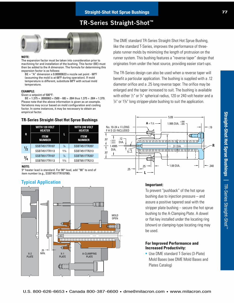
U.S. 800-626-6653 Canada 800-387-6600 [email protected] www.milacron.com
77H
ot R
un
ner S
yste
ms | 4-Zone and 8-Zone Tim
er-Based SequencersStraight-Shot Hot Sprue Bushings
TR-Series Straight-Shot™
Stra
igh
t-Sh
ot H
ot S
pru
e B
ush
ing
s | TR-Series Straight-Shot ™
The DME standard TR-Series Straight-Shot Hot Sprue Bushing,
like the standard T-Series, improves the performance of three-
plate runner molds by minimizing the length of protrusion on the
runner system. This bushing features a “reverse taper” design that
originates from under the heat source, providing easier start-ups.
The TR-Series design can also be used when a reverse taper will
benefit a particular application. The bushing is supplied with a .12
diameter orifice and a .25 long reverse taper. The orifice may be
enlarged and the taper increased to suit. The bushing is available
with either 1/2" or 3/4" spherical radius, 120 or 240 volt heater and a 7/8" or 13/8" long stripper-plate bushing to suit the application.
R
WITH 120 VOLT HEATER
L
WITH 240 VOLT HEATER
ITEM NUMBER
ITEM NUMBER
1⁄2 SSBT4517TR107 7⁄8 SSBT4517TR207
SSBT4517TR113 13⁄8 SSBT4517TR213
3⁄4 SSBT6517TR107 7⁄8 SSBT6517TR207
SSBT6517TR113 13⁄8 SSBT6517TR213
TR-Series Straight-Shot Hot Sprue Bushings
1.4995DIA.
.12 DIA.
.31 DIA.
.25.25
.97
5.09
.97
.340
.191.995 DIA.
1.69 DIA.
No. 10-24 x LONGF H S (2) INCLUDED
+.000–.005
+.0000–.0005
R
L
5˚
A = 871
21
X-1PLATE
X-2PLATE
A-CLAMPINGPLATE
MOLDOPEN
.25 MIN.
Typical Application
NOTE:The expansion factor must be taken into consideration prior to machining for and installation of the bushing. This factor (BE) must then be added to the A dimension. The formula for determining this expansion factor is as follows:
BE = “A” dimension x 0.00000633 x nozzle set point - 68ºF (assuming the mold is at 68ºF during operation). If mold temperature is different, substitute 68ºF with actual mold temperature.
EXAMPLE: Given a setpoint of 500°F:
BE = 1.375 × .0000063 × (500 – 68) = .004 thus 1.375 + .004 = 1.379.Please note that the above information is given as an example. Variations may occur based on mold configuration and cooling factor. In some instances, it may be necessary to obtain an empirical factor.
Important:To prevent “pushback” of the hot sprue
bushing due to injection pressure – and
assure a positive tapered seal with the
stripper plate bushing – secure the hot sprue
bushing to the A-Clamping Plate. A dowel
or flat key installed under the locating ring
(shown) or clamping-type locating ring may
be used.
For Improved Performance and Increased Productivity: Use DME standard T-Series (3-Plate)
Mold Bases (see DME Mold Bases and
Plates Catalog)
NOTE: 5° heater lead is standard. For 90° lead, add “90” to end of item number (e.g., SSBT4517TR10790).

U.S. 800-626-6653 Canada 800-387-6600 [email protected] www.milacron.com
78H
ot
Ru
nn
er
Syste
ms |
4-
Zone
and
8-Z
one
Tim
er-B
ased
Seq
uenc
ers
Straight-Shot Hot Sprue Bushings
Straight-Shot™ Bushings Replacement Parts
Str
aig
ht-
Sh
ot
Ho
t S
pru
e B
ush
ing
s |
St
raig
ht-S
hot B
ushi
ngs
Repl
acem
ent P
arts
5˚ heater lead, with 48"long shielded leads
5˚
5˚
ITEM NUMBER* VOLTS WATTS L BUSHING SERIES
SSTC31 120 300 45⁄8 S, E & ER (Long Style), T & TR
SSTC32 240 300 45⁄8 S, E & ER (Long Style), T & TR
SSTC42 240 250 21⁄2 E & ER (Short Style)* Includes installation wrench.
Replacement Heaters for Straight-Shot Hot Sprue Bushings Standard
5˚
L
90˚
L
48"
THERMOCOUPLE
Available On Request:Heaters with 90° exit leads. Add “90” to item number.Example: SSTC3190
Straight-Shot Heater Installation and Removal Wrench (Included with heaters above).
ITEM NUMBER USED WITH
WR0875 SSTC31 & 32 Series
WR0874 SSTC42 Series
Replacement Parts for Discontinued Hot Sprue Bushings (HBT6630 through 6636), Temperature Controllers (PFC5) and Control Modules (FC5)
Threaded type thermocouple is spring loaded and supplied with cable and mini plug.
ITEM NUMBER
TCT4
DIA. LENGTH VOLTS WATTS ITEM NUMBER
1/4 21/2 240 200 HBTC2022*1/4 33/4 240 300 HBTC2032**
Thermocouple Cartridge Heaters
DIA. LENGTH WATTS VOLTS ITEM NUMBER
1/4 21/2 240 200 HBC2022*1/4 33/4 240 300 HBC2032**
Cartridge Heaters
Replacement Fuses for Temperature Control Modules (FC5) and Temper ature Controllers (PFC5)
See the DME Control Systems Catalog for new controllers.
ITEM NUMBER AMPS
ABC5 5
13X5 5
ID OD1/2
3/4
* Used with Hot Sprue Bushings 5 3⁄16 long; heater supplied with leads 48" long.
** Used with Hot Sprue Bushings 6 3⁄16 long; heater supplied with leads 46" long.

U.S. 800-626-6653 Canada 800-387-6600 [email protected] www.milacron.com
text 79H
ot R
un
ner S
yste
ms | 4-Zone and 8-Zone Tim
er-Based SequencersIn
teg
rally
Hea
ted
Ho
t Sp
rue B
ush
ing
s | Features and Benefits
Integrally Heated Hot Sprue Bushings
Integrally Heated Sprue Bushings .750" SERIES
The Integrally Heated Sprue Bushing is uniquely designed for high performance and reliability for direct gating
applications, even with the most demanding molding cycles and plastic resins.
The product’s advanced heat transfer capability is attributed to its integrally heated design, resulting in a more
uniform heat profile. Maximum heat 600ºF.
A replaceable thermocouple is strategically located near the melt flow channel to optimize processing conditions
with all thermoplastics.
Features and Benefits: Distributed watt density – maintains a more uniform heat profile.
High refractory insulation – provides superior heat transfer.
Streamlined flow channel – minimizes pressure loss.
Fully sealed construction – maintains highest product reliability.
High-grade alloy steel construction – increases durability and longer life.
Replaceable thermocouple – allows for Type “J” or “K”.
Direct Gating Diagram
Tip Styles and Flow Diagrams
Insulating Washer
Locating Ring
Water Line
Wire ChannelPower & T/C Bushing Leads
Insulating Washer
Sprue Tip Extra Stock Sprue Tip
Maximum heat 600ºF
Recommended for Commodity Resins
Only

U.S. 800-626-6653 Canada 800-387-6600 [email protected] www.milacron.com
80 Integrally Heated Hot Sprue Bushings
Integrally Heated Sprue Bushings .750" SERIES USER GUIDE
Inte
gra
lly H
ea
ted
Ho
t S
pru
e B
ush
ing
s |
Us
er’s
Gui
de
Integrally Heated Sprue Bushings
The DME Integrally Heated Sprue Bushing is an exclusive medium volume bushing with the ability to
process a wide range of resins. Its streamlined flow channel terminates in a reverse taper gate, providing
minimal pressure loss and allowing for rapid gate freeze. The formation of a small gate stub on the part
or runner results in a machine hold-time reduction, with no increase in sink marks on the part.
The Sprue Bushing’s superior heat transfer capacity is attributed to its integrally heated design. To optimize
processing conditions for all thermoplastics, a replaceable thermocouple is strategically located near the
flow channel. The Integrally Heated Sprue Bushing has a .187" flow diameter, and is offered in two
head styles and two gate styles to suit a broad range of applications.
Gating Options for Sprue BushingsSPRUE GATESuitable for most applications, the Sprue Gate is provided as standard on the Heated Sprue Bushing.
(Please note that this gate style is not intended for machining.) The press fit areas are held
to ± .0005".
EXTRA STOCK SPRUE GATEThe Extra Stock Sprue Gate is available for applications requiring machining of the gate area for runner
profiles, part contours, or adjustment of the bushing height. The .750" diameter bushing has .500” of
extra stock. The press fit areas are held to ± .0005”.
Head Options for Sprue Bushings.500" Radius*Provided with a 0.500" radius to mate with 0.500" radius machine nozzles.
Reinforced contact area for improved strength and heat transfer.
.750" Radius*Provided with a 0.750" radius to mate with 0.750" radius machine nozzles.
Reinforced contact area for improved strength and heat transfer.
*Other radii are available by special request.
Gating Options Gate DiametersSprue .080" to .125"* max. (2mm to 3.2mm* max.)Extra Stock Sprue .080" to .125"* max. (2mm to 3.2mm* max.)
Gating Options
Commodity Resin
Sprue Extra Stock Sprue
Resin ViscosityGating Options High Medium Low
Sprue 50g 150g 300gExtra Stock Sprue 50g 150g 300g
.750" Series Resin Compatibility.750" Series Maximum Shot Weights (0.080" Gate)
Reference: High Viscosity = Melt Flow (0.02 – 6); Medium Viscosity = Melt Flow (7 – 15); Low Viscosity = Melt Flow (16 – up). The values expressed in grams are for reference purposes only. Part dimensions, wall thickness, mold condition, and molding parameters must also be considered.
* Re-machine gate diameter, if necessary, for larger shot weights. Maintain gate angle and remove all machine marks.
Contact DME when exceeding minimum shot weight and process heat temperature at 600ºF.
= Recommended

U.S. 800-626-6653 Canada 800-387-6600 [email protected] www.milacron.com
81Integrally Heated Hot Sprue Bushings
Integrally Heated Sprue Bushings .750" SERIES
Inte
gra
lly H
ea
ted
Ho
t Sp
rue B
ush
ing
s | O
ptions and Dim
ensions
.190(4.8mm)
1.9900 dia.(50.55mm)
.8750(22.23mm)
.750 R(19.1mm)
.440(11.2mm)
.125(3.2mm)
1.060 dia.(26.9mm)
.500 Radius Style .750 Radius Style
.190(4.8mm)
.500 R(12.7mm)
1.9900 dia.(50.55mm)
.635 dia.(16.1mm)
Head Options
Gating Options / Bushing Dimensions
L dim.
.7500 dia.(19.05mm)
L2 dim.
.187(4.7mm)
.080 dia.(2.0mm)
.740 dia.(18.8mm)
.25(6.3mm)
Sprue Gate
Note**
6°
* Dimensions include extra length.
** This surface cannot be machined, modified or altered.
*** Maximum machining stock; only this area can be machined.
Dimensions are in inches; millimeters are in parentheses.
Note: For additional gate dimensions see page 82
.75(19.1mm)
L2 dim.Note*
.375(9.5mm)Note***
.187 dia.(4.7mm)
Flow Channel
.7500 dia.(19.05mm)
.500 (12.7mm)Extra Length
L dim.Note*
Extra Stock Sprue Gate

U.S. 800-626-6653 Canada 800-387-6600 [email protected] www.milacron.com
82 Integrally Heated Hot Sprue Bushings
Integrally Heated Sprue Bushings .750" SERIES SPECIFICATIONS
Inte
gra
lly H
ea
ted
Ho
t S
pru
e B
ush
ing
s |
Sp
ecifi
catio
ns
Gate Style L Dim. L2 Dim. .500 Radius Head .750 Radius Head Watts Thermocouple
Sprue 2.375" (60.3) 1.500" (38.1) SB031000 SB031001 315 MT020020
2.875" (73.0) 2.000" (50.8) SB031008 SB031009 370 MT020020
3.375" (85.7) 2.500" (63.5) SB031016 SB031017 425 MT020020
3.875" (98.4) 3.000" (76.2) SB031024 SB031025 480 MT020020
4.375" (111.1) 3.500" (88.9) SB031032 SB031033 535 MT020021
Gate Style L Dim. L2 Dim. .500 Radius Head .750 Radius Head Watts Thermocouple
Extra Stock Sprue 2.875" (73.0) 2.000" (50.8) SB031004 SB031005 315 MT020020
3.375" (85.7) 2.500" (63.5) SB031012 SB031013 370 MT020020
3.875" (98.4) 3.000" (76.2) SB031020 SB031021 425 MT020020
4.375" (111.1) 3.500" (88.9) SB031028 SB031029 480 MT020020
4.875" (123.8) 4.000" (101.6) SB031036 SB031037 535 MT020021
Mold Power-Thermocouple Input ConnectorA Single-Zone Power-Thermocouple Input Connector is
available for mounting in or on the mold to accept the power-
thermocouple cable from the mainframe. The water-resistant
connector has an integral retaining latch for a secure cable
connection and numbered screw-type terminals for power
and thermocouple lead wires.
*Can be mounted on top of mold
Armored Mold Power-Thermocouple CablesSingle-Zone Mold Power-Thermocouple Cables are
constructed of special lead wire for use in high temperature
environments, and are available to connect the mainframe to
the input connector on the mold. Available in lengths of 10 or
20 feet. Integral retaining latches on the mainframe and mold
connections provide secure cable connections. Connector
configurations ensure proper insertion of cable.
Recommended Mold Pocket LayoutFor Mold Power-Thermocouple Input Connector (CKPTIC1)
ITEM NUMBER
MPTC10
MPTC20
ITEM NUMBER
CKPTIC1
For complete information on temperature controls, please see DME Control Systems Catalog.
All specifications are subject to change without notification.Dimensions are in inches; millimeters are in parentheses.
Right (Standard)*
* Standard Lead exit –60" (1.52m) wrapped - 600 volt leads;right angle lead exit; and 6" (15.2cm)stainless steel, square-lock armored cable.
1.360.91
0.901.180 0.25 R 0.55
MOLD SURFACE
MOUNTING SURFACE
1.00
2.00
4.00 MIN.
1.452.00
0.460.32
NO. 4-40 NC-2B TAP.50 DEEP MIN. (2) PLACES
0.25 R
1.503.50
0.14REF
REF

U.S. 800-626-6653 Canada 800-387-6600 [email protected] www.milacron.com
83In
teg
rally
Hea
ted
Ho
t Sp
rue B
ush
ing
s | M
achining Dim
ensionsIntegrally Heated Hot Sprue Bushings
Integrally Heated Sprue Bushings .750" SERIES
.750" Series Bore & Gate Dimensions
L2 dim. + exp.(See page 4 for L2 dim.)
2.05 dia.(52.1mm) .8752
a
(22.23mm)a
.110(2.8mm)
Gate
1.9910b
dia.(50.57mm)
b
Insulating Washer Option Standard Bore
L2 dim. – .125 + Exp.L2 dim. – (3.2mm) + Exp.{See page 4 for L2 dim.}
.860 dia.(21.8mm)
.500 min.(12.7mm)
Bottom Washer
Top Washer
.125(3.2mm)
.125(3.2mm)
1.125(28.6mm)
.235(6.0mm)
.760(19.3mm)
.080(2.0mm)
.125(3.2mm)
Water Line
.860 dia.(21.8mm)
.7505a
dia.(19.06mm)
a
.118(3.0mm)
.118 min.(3.0mm)
.7505a
dia.(19.06mm)
a
30° max.
.860 dia.(21.8mm)
.493 max.(12.5mm)
Thermal Expansion (Exp.) FormulasExp. in = L2 in. × 6.88 × 10⁻⁶ × (Processing Temp. – 70°F)
Exp. mm = L2 mm × 13 × 10-6 × (Processing Temp. – 21°C)
Ref: 10-6 = 0.000001
All specifications are subject to change without notification.
Dimensions are inches. Millimeters are in parentheses.
in: + 0.0005– 0
mm: + 0.01– 0
Tol. “a” Table
in: + 0.0010– 0
mm: + 0.02– 0
Tol. “b” Table
Top Bottom
Item Number MAX10015 MAX10027
O.D. 1.99 (50.5mm)
1.99 (50.5mm)
I.D. 1.07 (27.2mm)
.810 (20.6mm)
Thickness .125 (3.2mm)
.125 (3.2mm)
Insulating Washer Specifications
Sprue Gate Extra Stock Sprue Gate
Bore & Gate Tolerances
Note: Insulating Washers are not required, but are recommended for high tem-perature applications.

U.S. 800-626-6653 Canada 800-387-6600 [email protected] www.milacron.com
84 Integrally Heated Hot Sprue Bushings
Integrally Heated Sprue Bushings .750" SERIES
Inte
gra
lly H
ea
ted
Ho
t S
pru
e B
ush
ing
s |
Lo
catin
g Ri
ng &
Key
ing
Opt
ions
Operating & Servicing InstructionsThe Integrally Heated Sprue Bushing bodies are identical in design, but differ in length and head style. All Sprue Bushings
feature an integrated heater; Type “J” thermocouple; 60” wrapped - 600 volt leads; right angle lead exit; and 6” stainless
steel, square-lock armored cable.
Start-Up/Operating ProceduresIf the temperature controller does not utilize “soft start” technology, set the controller to 200°F (93.3°C) in automatic mode
or 10% in manual mode. Allow bushing to “soak” for 15 minutes before increasing to processing temperature. This step will
allow the unit to dissipate potential moisture and prolong heater life.
Power Requirements 240 Volts AC – 15 amp fuse
Grounding – Integrally Heated Bushings utilize the direct contact of the bushing, mold plates, and machine platens to establish a path for grounding.
*WARNING*There must be a ground present between the mold “hot half” and the temperature control system or damage may occur to the bushing, thermocouple
and/or temperature control system.
Maximum heat 600ºF
For 5/16 - 18 SHCS(2 places)
1.625 R(41.3mm)
5.490 dia.(139.4mm)
3.990" dia(101.3mm)
Customer to machine counterbore.
.510(12.9mm)
1.135(28.8mm)5/16 - 18 THD
Jack Screw location(2 places)
Locating Ring Dimensions
ITEM NUMBER
L.R.D.
ML010012 3.990” (101.3mm)
Machining Options for Keying
.75 R min.(19.1mm)
.83 R min.*(21.1mm)
Dowel Pin Socket HeadCap Screw
*Centerline for #10 Screw
Dimensions are in inches; millimeters are in parentheses.

DME Hot Runner Services
TOTAL SUPPORT FOR YOUR
HOT RUNNER SYSTEMS

U.S. 800-626-6653 Canada 800-387-6600 [email protected] www.milacron.com
text86H
ot
Ru
nn
er
Syste
ms |
4-
Zone
and
8-Z
one
Tim
er-B
ased
Seq
uenc
ers
Moldflow Services — Optimize Part and Mold Design
Hot Runner ServicesH
ot
Ru
nn
er
Serv
ices |
M
oldf
low
Ser
vice
s —
Opt
imiz
e Pa
rt a
nd M
old
Des
ign
Comprehensive Analysis and ModelingWith today’s shrinking time-to-market window, development speed is
essential. As part of its commitment to the molding industry, DME is now
offering Moldflow™ analysis to help optimize part and mold design –
especially for hot runner molds. DME is the first mold technologies
supplier to earn Moldflow’s silver certification in this advanced technology.
A Competitive AdvantagePredictive analysis, utilizing Moldflow software, yields tremendous
benefits, including:
Optimize part design
Reduce time-to-market
Save cost and time on mold tryouts
Lower development and production costs
Provide a framework to establish reputable processes
Improve product quality
Decrease cycle times
What is Moldflow?DME uses Moldflow Plastics Insight™ (MPI) software which is an
integrated suite of analysis tools that utilize CAD files and apply advanced
Finite Element Analysis (FEA) techniques to quickly and easily enable a
virtual “what if” design environment before initiating mold construction.
MPI provides in-depth part/mold design and process parameter optimization.
This is in contrast to Moldflow Plastics Advisor™ (MPA) which is primarily
useful for parts with low to medium complexity, conceptual designs,
and quick part design validation. DME is a certified, licensed provider of
Moldflow analysis services.
Mold Fill AnalysisThe Mold Fill module uses predictive technology to simulate the filling
process. Key analyses include:
Optimize the number, size, and location of gates
Balance the runner system design
Reduce material stress levels
Predict weld line locations
Validate pressure and temperature distribution within the mold
Optimize processing conditions – including melt temperature, injection
rate, and cavity pressure
Grill stackmold

U.S. 800-626-6653 Canada 800-387-6600 [email protected] www.milacron.com
text 87H
ot R
un
ner S
yste
ms | 4-Zone and 8-Zone Tim
er-Based Sequencers
Moldflow Services — Optimize Part and Mold Design
Hot Runner ServicesH
ot R
un
ner S
erv
ices | M
oldflow Services —
Optim
ize Part and Mold D
esign
Mold Pack Analysis
Building on the results of a Mold Fill analysis, the Mold Pack
module optimizes the packing phase to ensure a uniform packing
condition. As an indication of part warpage, volumetric shrinkage
is evaluated and the pack pressure profile is optimized. The result
is minimized warpage with an improved surface appearance.
Mold Cool Analysis
The Cool Analysis module assesses an existing cooling layout
to determine potential molding problems. Steel types, cooling
channel sizes, bubblers, baffles, coolant temperatures, and flow
rates are all evaluated. Using this analysis, the Mold Cool module
recommends practical tooling design changes to ensure uniform
cooling. Mold Cool takes into account:
Number, location, depth, and pitch of cooling channels
Steel types
Cooling circuit layouts
Coolant temperatures and flow rates
Cycle times
Warp Analysis
Using the results from the Fill and Cool analyses,
the Warp Analysis module enables prediction of
plastic part shrinkage and warpage. Warp Analysis
diagnoses the cause(s) of warping and recommends
the appropriate solution, such as gate location
changes, design parameter changes, and reduction
of wall thickness variations.
MPI 3D
MPI 3D addresses a class of problems previously
unsolvable using traditional Finite Element Analysis
techniques. In thick-walled parts, molten plastic can
flow in all directions. Using a proven methodology
based on a solid tetrahedral, finite element volume
mesh, MPI 3D enables true, three-dimensional
simulations on thick-walled parts.
Where Do I Start?
Contact your DME representative for more
information regarding Moldflow Services. The
DME Applications Engineering Department is
available to provide a customized Moldflow
analysis and assist you in maximizing the results
of your next application.

U.S. 800-626-6653 Canada 800-387-6600 [email protected] www.milacron.com
text88H
ot
Ru
nn
er
Syste
ms |
4-
Zone
and
8-Z
one
Tim
er-B
ased
Seq
uenc
ers
Mold Filling/Mold Cooling Analysis Quote Request Form
Hot Runner ServicesH
ot
Ru
nn
er
Serv
ices
| Cu
stom
er R
eque
st fo
r Dat
a –
Mol
d Fi
lling
/Mol
d Co
olin
g An
alys
is
THIS FORM IS REQUIRED FOR ALL ANALYSIS WORK FOR EACH PARTNOTE: Changes made after this form is received require written confirmation
Fax completed form to 248-544-5707 or email [email protected]

U.S. 800-626-6653 Canada 800-387-6600 [email protected] www.milacron.com
89H
ot R
un
ner S
yste
ms | 4-Zone and 8-Zone Tim
er-Based SequencersH
ot R
un
ner S
erv
ices | D
ME Hot Runner Service Center
DME Hot Runner Service Center
Hot Runner Services
Ensuring the Productivity of every Hot Runner System
Full-Service Hot Runner Support
Mold technology leader DME - known for servicing its customers every step of the way - provides total support for your
hot runners. No matter what brand of hot runner you have, DME will repair, reconfigure or even totally rebuild it to ensure
maximum uptime and performance of your system.
A Dedicated Center for Hot Runner SystemsOur new Hot Runner Service Center, located in Madison Heights, Mich., is exclusively dedicated to supporting your hot runner
systems. Staffed by a team whose sole focus is hot runner systems, we’re quickly able to get your system operating at maximum
efficiency. This group has over three decades of experience installing, assembling, and repairing hot runner systems. And,
because we’re centrally located, we can get your system back in your shop quickly and cost-effectively.
Unrivaled Support When and Where You Need ItSince the 1970s, DME has developed and marketed a full spectrum of hot
runner systems and components. From Moldflow analysis to turnkey hot half
systems and everything in between, the DME family of hot runner products
and services offers a comprehensive array of solutions for a wide range of
applications. Whether your need is for standard, off-the-shelf components,
customer engineered manifolds, or fully assembled systems ready for bolt-on
installation, DME has a proven solution to match your application.
Moldflow ServicesAs the first mold technologies supplier to earn Moldflow’s silver certification,
DME is highly adept at applying Finite Element Analysis (FEA) techniques to
help optimize part and mold design. Whether you need Mold Fill, Mold Pack,
Mold Cool or Warp analyses, DME can assist you in maximizing the results of
your next application.
Applications Engineering and Technical ServiceOur dedicated and experienced team of mold designers and applications
engineers assists DME customers with product selection, system design, per-
formance analysis and technical advice. DME technical service representatives
are globally located for complete coverage and quick availability no matter
where your hot runner production takes place. Technical experts employed
worldwide are available for start-ups, personnel training or system service.
Comprehensive Hot Runner ServiceStaffed by a team whose sole focus is hot runner systems, the DME Hot
Runner Service Center offers a single source for hot runner system
optimization and maintenance. Our services include expedited repairs,
system cleaning, system rebuilds, re-configuration and mold tryouts for
virtually any type of hot runner system.
The DME family of hot runner products and services offers
a comprehensive array of solutions
for a wide range of applications.
Hot Runner Services Overview
gapplications.

U.S. 800-626-6653 Canada 800-387-6600 [email protected] www.milacron.com
text90H
ot
Ru
nn
er
Syste
ms |
4-
Zone
and
8-Z
one
Tim
er-B
ased
Seq
uenc
ers
A Wide Range of ServicesWe recognize the value of your time - that’s why we’ve developed a comprehensive suite of hot runner ser-vices to provide a single source for maintenance and optimization of your system, even our competitor’s systems.Key services include:
System evaluationsRepairsSystem cleaning and rewiring of all hot runner systems - including complete bake-outTotal system rebuildTotal restoration of flooded systemsRe-configurationOperating trainingAll machining capabilities
Cost-Effective Reconfiguration When your process needs change, without a significant
tooling change, we can adapt your hot runner to the new
process. Whether it’s a material switch, or a part design
change, DME can help reconfigure your existing system.
Training Maximizes Productivity, Speeds Set-UpThe DME Hot Runner Service Center can provide comprehensive operator training in start-up or prototyping. Our hands-on programs help your operators get up-to-speed, or stay current on hot runner technology.
Preventative Maintenance (PM)It is important to protect and update your hot runner system to ensure it is running at the highest efficiency. The PM Program is designed to prevent system equip-ment failure before it occurs. We will enhance equip-ment reliability by replacing worn components before they fail.
Maximizes system performanceReduces cost of replacementEnsures peak part qualityDecreases system downtimeProtects your investment
The PM Program can be set up either by system cycles or by scheduled PM
Rebuilds Ensure PerformanceAfter tens of thousands of cycles you may have noticed your system just doesn’t perform the way it used to. Or maybe you’ve run high-temperature engineered materials and the tolerances just aren’t as tight. Key benefits of system rebuilds include:
Cost savings of at least 40% as compared to new systems
Extended life for your tool
Maximizing system uptime and performance
Improved finished part quality
Whether you need a total system rebuild, or a simple cleaning and inspection DME can help. System rebuilds can be performed on any brand of hot runner system and typically include:
Complete bake-out cleaning
Check and replace heaters and thermocouples
Inspect and correct wiring
Replace seals and bushings
Clean or replace nozzle components
Check all dimensions and re-assemble system
Repairs Get You Back Up QuicklyTime is money. When a critical tool is out of commission, productivity is lost and production schedules can be threatened. We understand this at DME. That’s why our team of hot runner repair specialists are always available to get you back in service.
Whether you’re experiencing leaks, heating issues, flow problems, or would simply like a system bake-out, we’ll repair your system quickly and cost-effectively.
Standard turnaround for repairs on systems from 1-12 drops (depending on parts availability for non-DME systems) is 5 working days or less. If your system has over 12 drops, contact us for an estimated turnaround time. And, we offer emergency 24-hour turnaround service.
Mold Tryouts
We also offer mold tryouts at the Hot Runner Service Center. Injection molding machines from 85 to 250 tons are available to run your mold and ensure proper performance.
DME Hot Runner Service Center
Hot Runner ServicesH
ot
Ru
nn
er
Serv
ices |
D
ME
Hot R
unne
r Ser
vice
Cen
ter

DME Obsolete Replacement Parts
REPLACEMENT PARTS FOR OBSOLETE
HOT RUNNER SYSTEMS & NOZZLES

U.S. 800-626-6653 Canada 800-387-6600 [email protected] www.milacron.com
page content
text 92
Obsolete Replacement Parts
page content
92Obsolete Replacement Parts
Mini Gate-Mate® Nozzles
NOZZLE SUB-ASSEMBLY
(ORDER TIP SEPARATELY)
INCLUDES
1 2 3 4
ITEM NUMBER
HEATER TYPE
NOZZLE BODY HEATER WATTS THERMO-
COUPLESEAL RING
GMB0110 CAST-IN GMB0105 CIH0100 250 N/A (INTEGRAL) EHR7155
GMB0118 SQUARE COIL GMB0105 SCH0004 250 TCG0100
ITEM NUMBER
TIP STYLE
GMT0100 STANDARD
GMT4101 WEAR RESISTANT
Mini Gate-Mate® TipsContact DME for tip recommendations and assistance with your application.
ANOZZLE
ASSEMBLY(INCLUDES GMT2 TIP)
NOZZLE SUB ASSEMBLY
(TIP ORDERED SEPARATELY)
INCLUDES1 2 3 4
NOZZLE BODY
SQUARE COIL
HEATERWATTS THERMO-
COUPLESEAL RING
2.000 GMB0050 GMB0150 GMB0060 SCH0060 250 TCG0060
EHR7155
2.500 GMB0051 GMB0151 GMB0061 SCH0061 300 TCG0061
3.000 GMB0052 GMB0152 GMB0062 SCH0062 350 TCG0062
3.500 GMB0053 GMB0153 GMB0063 SCH0063 400 TCG0063
4.000 GMB0054 GMB0154 GMB0064 SCH0064 425 TCG0064
5.000 GMB0055 GMB0155 GMB0065 SCH0065 500 TCG0065
6.000 GMB0056 GMB0156 GMB0066 SCH0066 500 TCG0066
NOTES:1. Items 1 thru 4 are available separately
for replacement purposes2. Items 2 is 240 VAC, 36" leads, 34" fiberglass
lead protection3. Item 3 is type J, with 36" leads, 34"
fiberglass lead protection4. Item 4 (for replacement) is sold in packs
of 4 only
Gate-Mate® 4 Nozzles and Tips
INCLUDES1 2 3
NOZZLE BODY
FRONT LOAD HEATER WATTS SEAL
RING
GMB0060 SCH1060 250
EHR7155
GMB0061SCH1061
300SCH2061
GMB0062SCH1062
350SCH2062
GMB0063SCH1063
400SCH2063
GMB0064SCH1064
425SCH2064
GMB0065SCH1065
500SCH2065
GMB0066SCH1066
500SCH2066
NOTES:1. Items 1, 2 and 3 are available separately for replacement purposes2. Item 2 is 240 VAC, type J thermocouple, 36" leads, 34" Teflon lead protection3. Item 3 (for replacement) is sold in packs of 4 only
TIP STYLE
TIP ITEM NUMBER
O DIA.
TIP LENGTH
TIP DIA.
HOLE DIA.
STANDARD GMT2 .044 MIN.
1.730
.024
N/A
WEAR RESISTANT GMT0400 .055 MIN.
SUPER SHARP GMT0301 .030 MIN.
.010SUPER SHARPWEAR RESISTANT GMT0401 .055 MIN.
THRU HOLE GMT0302* .030 MIN. .050 MAX
1.690 .090 .050THRU HOLE
WEAR RESISTANT GMT0402* .055 MIN.
NO HOLE GMT0303 .044 MIN. 1.730 .024 N/A
Gate-Mate® 4 Tips
NOTES:1. Thru hole tip is designed .040 shorter in length to be a direct
replacement for the standard tip; use a .030 to .060 diameter gate
2. A .030 minimum diameter gate is recommended when using the super sharp tip
3. Contact DME for tip recommendations and assistance with your application
* Contact DME for details to modify thru hole tips for larger “O” diameters
ITEM NUMBER
EHR7155
Replacement Seal Rings
ITEM NUMBER
6548
Mini Gate-Mate Bushing Locating Ring
1/2 SPH. RADIUS BUSHING SUB-ASSEMBLY
ITEM NUMBER HEATER TYPE
GMB0116 SQUARE COIL
GMB0111 CAST-IN
FLAT BUSHING SUB-ASSEMBLY
ITEM NUMBER HEATER TYPE
GMB0117 SQUARE COIL
GMB0112 CAST-IN
Ga
te-M
ate
® N
ozzle
s

U.S. 800-626-6653 Canada 800-387-6600 [email protected] www.milacron.com
93H
ot R
un
ner S
yste
ms | 4-Zone and 8-Zone Tim
er-Based SequencersC
usto
m H
ot R
un
ner S
yste
ms | N
ew Products
Obsolete Replacement Parts
Gate Shell Insulators
Ga
te S
hell In
su
lato
rs
Gate Shell Insulators
Improves insulation in the tip area
Provides seal-off to eliminate material degradation in threaded area of tip
Minimizes material in gate area to allow for faster color changes
Withstands temperatures up to 550° F
GATE SHELLINSULATOR
D DIA.
D DIA.
ITEMNUMBER
.748GSI0001
GSI0002
1.248GSI0003
GSI0004
.748GSI0005
GSI0006
FOR BUSHING OR NOZZLE STYLE FOR TIP STYLE ITEM
NUMBER
Gate-Mate 4 Nozzle
Standard, Super Sharp, No Hole GSI0001
Thru Hole GSI0002
Jumbo Gate-Mate Bushing or Nozzle
Standard GSI0003
Thru Hole GSI0004
Medium Gate-Mate Bushing
Standard, Super Sharp, No Hole GSI0005
Thru Hole GSI0006
APPLICATION NOTES:1. Use only with bushings, nozzles and tip styles shown in the reference chart above2. Gate machining must be done according to DME specifications3. Nozzle tip cannot be altered in any way for the Gate Shell Insulator
to perform properly4. If dissimilar resins are to be processed in the same mold, it is recommended that
their processing temperatures be within a similar range5. For best results, the outer surface of the tip should be free from all resin before
the Gate Shell Insulator is installed or used
Typical Application

U.S. 800-626-6653 Canada 800-387-6600 [email protected] www.milacron.com
page content
text94H
ot
Ru
nn
er
Syste
ms |
4-
Zone
and
8-Z
one
Tim
er-B
ased
Seq
uenc
ers
page content
94Obsolete Replacement Parts
Cu
sto
m H
ot
Ru
nn
er
Syste
ms |
In
dex
94 Obsolete Replacement Parts
Auto-fixed® “Integral Heater” Micro Probes (240 VAC, T/C Type J, 48" Leads)MATERIAL: AISI D-2 STEELHARDNESS: 50-55 HRC
ITEM NUMBER* A B WATTSAFIP331090 3.095 2.720 110AFIP336090 3.595 3.220 130AFIP341090 4.095 3.720 150AFIP346090 4.595 4.220 170
ITEM NUMBER LEAD LENGTHTC9900 48"
ITEM NUMBER*
RAF3062*Package of 10.
Replacement Thermocouple
Register RingMATERIAL: AISI H-13 STEEL HARDNESS: 48-52 HRC I.D. = .313 O.D.= 1.000
B
A
.375
.312 DIA
Components for Micro Cool One®
Solid Block Designs
Inte
rna
lly H
ea
ted
Ho
t R
un
ner
Syste
ms |
Co
mpo
nent
s fo
r Mic
ro C
ool O
ne®
Thermocouple (T/C) Distributor Tube Heaters (240 VAC, T/C Type J, 34" Leads)Distributed wattage heater design for more uniform temperature control. Sealed, flexible teflon covered leads
to prevent lead damage and improve moisture resistance.
DIA (AMPS)* ITEM NUMBER OVERALL
LENGTHHEATED LENGTH WATTS
.375 (10 AMP)
HCTC034 5.000 4.000 320HCTC0345 5.500 4.500 340HCTC035 6.000 5.000 400HCTC0355 6.500 5.500 430HCTC036 7.000 6.000 450HCTC0365 7.500 6.500 470HCTC037 8.000 7.000 480
DIA (AMPS)* ITEM NUMBER OVERALL
LENGTHHEATED LENGTH WATTS
.375(10 AMP)
HCTC0375 8.500 7.500 515
HCTC038 9.000 8.000 550
HCTC039 10.000 9.000 650HCTC0310 11.000 10.000 710HCTC0311 12.000 11.000 720
HCTC0312 13.000 12.000 760HCTC0313 14.000 13.000 810
*(AMPS) = Amperage requirement for temp. control module.
Distributor TubesMATERIAL: AISI 4140 STEELHARDNESS: 28-35 HRC
End CapMATERIAL: AISI 4140 STEEL
ITEM NUMBER LENGTH
HT050312 11.82
HT050316 15.76
ITEM NUMBEREC1105
Components for Micro Cool One® Split Plate/Solid Block Designs
NOTE: Probes are special order only
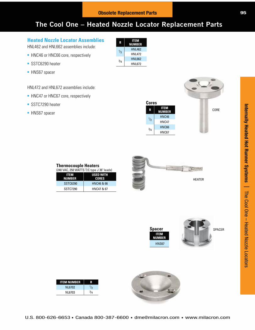
U.S. 800-626-6653 Canada 800-387-6600 [email protected] www.milacron.com
page content
text 95H
ot R
un
ner S
yste
ms | 4-Zone and 8-Zone Tim
er-Based SequencersObsolete Replacement Parts
Cu
sto
m H
ot R
un
ner S
yste
ms | N
ew Products
95Obsolete Replacement Parts
The Cool One – Heated Nozzle Locator Replacement Parts
Inte
rna
lly H
ea
ted
Ho
t Ru
nn
er S
yste
ms | The Cool O
ne – Heated Nozzle Locators
R ITEM NUMBER
1⁄2HNL462HNL472
3⁄4HNL662HNL672
CoresR ITEM
NUMBER
1⁄2HNC46
HNC47
3⁄4HNC66
HNC67
Thermocouple Heaters(240 VAC, 250 WATTS T/C type J 36" leads)
ITEM NUMBER
USED WITH CORES
SSTC6290 HNC46 & 66
SSTC7290 HNC47 & 67
SpacerITEM
NUMBER
HNS67
ITEM NUMBER R
NL6702 1⁄2NL6703 3⁄4
CORE
SPACER
HEATER
Heated Nozzle Locator AssembliesHNL462 and HNL662 assemblies include:
HNC46 or HNC66 core, respectively
SSTC6290 heater
HNS67 spacer
HNL472 and HNL672 assemblies include:
HNC47 or HNC67 core, respectively
SSTC7290 heater
HNS67 spacer

U.S. 800-626-6653 Canada 800-387-6600 [email protected] www.milacron.com
page content
text 96
Obsolete Replacement Parts
96 Obsolete Replacement Parts
The Cool One – End Caps and Distributor Tubes
Distributor TubesMATERIAL: AISI P-20 STEELHARDNESS: 28-35 HRC
NOTES:
Stainless Steel Distributor Tubes available on special order for molding highly corrosive plastics materials.
LENGTH
O.D. I.D.
.03 × 45° TYP.
End Caps (for use with solid distributor block designs)MATERIAL: AISI 4140 STEEL
End caps provide concentricity between distributor tube and distributor bore. Thread
accommodates heater stop or lead wire protector.
END CAPS FOR SPLIT PLATE DESIGNS: Moldmaker to supply to suit.
ITEM NUMBER
DIA. A
DIA. B THREAD USED WITH
DIST. BORE/TUBE
EC1207 1.249 0.875 5⁄8"- 11 1.25 DIA./.87 O.D.
EC2015 1.999 1.625 3⁄4"- 10 2.00 DIA./1.62 O.D.A DIA.
THREAD
B DIA.+ .000– .002
+ .002– .000
1.50
.56
USED WITH 2.00 DIAMETER DISTRIBUTOR BORE/CHANNEL
LENGTHI.D. = .62 O.D. = 1.62
ITEM NUMBER
10" HT150510
18" HT150518
24" HT150524
29" HT150529
34" HT150534
40" HT150540
46" HT150546
USED WITH 1.25 DIAMETER DISTRIBUTOR BORE/CHANNEL
LENGTHI.D. = .50 O.D. = .87
ITEM NUMBER
6" HT07046
10" HT070410
16" HT070416
20" HT070420
24" HT070424
29" HT070429
34" HT070434
Inte
rna
lly H
ea
ted
Ho
t R
un
ner
Syste
ms |
Th
e Co
ol O
ne –
End
Cap
s &
Dis
trib
utor
Tub
es

U.S. 800-626-6653 Canada 800-387-6600 [email protected] www.milacron.com
page content
text 97H
ot R
un
ner S
yste
ms | 4-Zone and 8-Zone Tim
er-Based SequencersObsolete Replacement Parts
Cu
sto
m H
ot R
un
ner S
yste
ms | N
ew Products
97Obsolete Replacement Parts
The Cool One – Thermocouple Distributor Tube Heaters
Inte
rna
lly H
ea
ted
Ho
t Ru
nn
er S
yste
ms | The Cool O
ne – Thermocouple D
istributor Tube Heaters
DIA. (AMPS)*
ITEM NUMBER LENGTH WATTS
.500 (10 AMP)
HCTC044 4" 380HCTC045 5" 500HCTC046 6" 600HCTC047 7" 700HCTC048 8" 820HCTC049 9" 920
HCTC0410 10" 1030HCTC0411 11" 1140HCTC0412 12" 1250HCTC0413 13" 1350HCTC0414 14" 1460HCTC0415 15" 1570HCTC0416 16" 1680HCTC0417 17" 1780HCTC0418 18" 1900HCTC0419 19" 2010HCTC0420 20" 2110HCTC0421 21" 2220HCTC0422 22" 2330HCTC0423 23" 2400HCTC0424 24" 2400HCTC0425 25" 2400HCTC0426 26" 2400HCTC0427 27" 2400HCTC0428 28" 2400HCTC0429 29" 2400HCTC0430 30" 2400
.625 (10 AMP)
HCTC055 5" 620HCTC056 6" 750HCTC057 7" 880HCTC058 8" 1020HCTC059 9" 1160
HCTC0510 10" 1300
Thermocouple (T/C) Distributor Tube Heaters(240 VAC, T/C type J, 34" leads)
*(AMPS) Amperage requirement for temperature control module.
NOTE: Heaters should be at least 2" shorter than distributor tube length in mold design.
DIA. (AMPS)*
ITEM NUMBER LENGTH WATTS
.625 (10 AMP)
HCTC0511 11" 1430
HCTC0512 12" 1570HCTC0513 13" 1700HCTC0514 14" 1840HCTC0515 15" 1980HCTC0516 16" 2110HCTC0517 17" 2250HCTC0518 18" 2390
.625 (15 AMP)
HCTC0519 19" 2520HCTC0520 20" 2660HCTC0521 21" 2800HCTC0522 22" 2930HCTC0523 23" 3070HCTC0524 24" 3200HCTC0525 25" 3340HCTC0526 26" 3480
.625(30 AMP)
HCTC0527 27" 3620HCTC0528 28" 3750HCTC0529 29" 3900HCTC0530 30" 4020
HCTC0531 31" 4160HCTC0532 32" 4300
HCTC0534 34" 4570
HCTC0535 35" 4710HCTC0536 36" 4840HCTC0537 37" 4980HCTC0538 38" 5120HCTC0539 39" 5250HCTC0540 40" 5390HCTC0541 41" 5520HCTC0542 42" 5520HCTC0543 43" 5520HCTC0544 44" 5520

U.S. 800-626-6653 Canada 800-387-6600 [email protected] www.milacron.com
page content
text 98
Obsolete Replacement Parts
98 Obsolete Replacement Parts
The Cool One – Components
Inte
rna
lly H
ea
ted
Ho
t R
un
ner
Syste
ms |
Th
e Co
ol O
ne –
Com
pone
nts
C DIA.
A DIA.
B DIA.
15° TYP.
.125 120° TYP.
.06 TYP.
+ .001– .000
+ .000– .001
+ .000– .001
Auto-Fixed™ “Integral Heater” Probes (240 VAC, T/C Type J Grounded, 48" Leads)MATERIAL: AISI D-2 STEEL HARDNESS: 50-55 HRC
Important: Dimensions shown in parentheses apply to larger probes AFIP5372 thru 622 only. Tolerances shown also apply to dimensions in paren-theses.
ITEM NUMBER** AFIP4 SERIES PROBES .394 (10 mm) DIAMETER
STRAIGHT EXIT LEADS
90° EXIT LEADS
A DIM.
B DIM. WATTS
AFIP4322 AFIP432290 3.220 2.720 135AFIP4372 AFIP437290 3.720 3.220 160AFIP4422 AFIP442290 4.220 3.720 185AFIP4472 AFIP447290 4.720 4.220 210
**lncludes probe, integral heater, thermocouple, adjustment ring and hold down nut.
ITEM NUMBER** AFIP5 SERIES PROBES .500 (12.9 mm) DIAMETER
STRAIGHT EXIT LEADS
90° EXIT LEADS
A DIM.
B DIM. WATTS
AFIP5372 AFIP537290 3.720 3.220 200AFIP5422 AFIP542290 4.220 3.720 230AFIP5472 AFIP547290 4.720 4.220 265AFIP5522 AFIP552290 5.220 4.720 295AFIP5572 AFIP557290 5.720 5.220 325AFIP5622 AFIP562290 6.220 5.720 360
Replacement Thermocouples(ALL PROBES)
ITEM NUMBER LEAD LENGTHTC9900 48"
Register RingsMATERIAL: AISI H-13 STEELHARDNESS: 48-52 HRC
ITEM NUMBER A DIM. B DIM. C DIM. USED WITHAFRR04N 1.062 .865 .387 AFIP4 SERIESAFRR05N 1.187 .937 .493 AFIP5 SERIES
Adjustment Rings(Packaged with all probes)
Hold-Down Nut(Packaged with all probes)THICKNESS = .500 THREAD = 1"- 8 HEX FLAT = 9⁄16
ITEM NUMBER† I.D. USED WITHRAF4062 .469 AFIP4 SERIESRAF5062 .565 AFIP5 SERIES
†Bag of 5 rings.
*Required for straight exit leads only.
A
B
.720 DIA.
.005 DIA. .384 DIA.(.490 DIA.)
.394 DIA.(.500 DIA.)
.500 REF.
.030 R.312 R.
.500.625
.157
45°
20°
+ .000– .001
+ .000– .001
Gate InsertsMATERIAL: AISI S-7 STEEL (pre-hardened)HARDNESS: 30-34 HRC
Hardness can be increased to a higher
value by heat treatment, if desired.
ITEM NUMBER O.D. I.D. USED WITH
AFGI04N 1.625 .875 AFIP4 SERIESAFGI10N 1.750 1.000 AFIP5 SERIES
ITEM NUMBER
AFN100
ITEM NUMBER
WR916
I.D. .062(GRIND TO SUIT)
90°
STRAIGHT
Hold-Down Nut Wrench*
2.500 .375R.
.187SPH. R..625 45°
O.D.
I.D.
+ .005– .000
AVAILABLE WITH STRAIGHT OR 90° EXIT HEATER LEADS
These probes feature a swaged in heating element which
is an integral part of the probe. A separate replaceable
thermocouple is installed in each probe as supplied. The
integral heater design provides highly efficient heat transfer,
uniform heat distribution and is guaranteed for one year.
NOTE: Probes are special order only

U.S. 800-626-6653 Canada 800-387-6600 [email protected] www.milacron.com
page content
text99
page content
99Obsolete Replacement Parts
99Obsolete Replacement Parts
The Cool One – Probes and Probe Heaters
Inte
rna
lly H
ea
ted
Ho
t Ru
nn
er S
yste
ms | The Cool O
ne – Probes and Probe Heaters
Auto-Fixed™ Probes (3" to 6" long)MATERIAL: AISI D-2 STEELHARDNESS: 50-55 HRC
LENGTH A ITEM NUMBER **
2.893 AFP3103.625 AFP4104.625 AFP5105.609 AFP610
** Includes probe, stop sleeve and hold down nut only.
These finned style Auto-Fixed probes employ a precision
engineered tip configuration that automatically “fixes” the
relationship between probe tip and gate, centering the probe
and limiting tip protrusion into the gate. Thermocouple
heaters are guaranteed for one year as detailed under the
heater chart below. Gate inserts (shown on next page),
pre-machined for use with these probes, can save
valuable machining time and help assure optimum
probe performance.
Auto-Fixed™ Finless Probes (3" to 6" long)MATERIAL: AISI D-2 STEELHARDNESS: 50-55 HRC
LENGTH A ITEM NUMBER **
2.893 AFPN3103.625 AFPN4104.625 AFPN5105.609 AFPN610
** Includes probe, stop sleeve and hold down nut only.
These finless style Auto-Fixed probes are available in the
same sizes as the finned probes above and also in lengths
up to 10". An optional register ring is available to provide
added stability at the probe tip if desired. As with the finned
probes, thermocouple heaters are guaranteed for one year
and pre-machined gate inserts are available.
NOTE: Due to minimum distance requirements specified, the AFPO310 and AFPN310 probes cannot be used in a Cool One system. They may, however, be used in an insulated runner system.
ITEM NUMBER FOR PROBE WATTS LENGTHAFTC2132 AFP(N)310 150 3.00AFTC2142 AFP(N)410 220 3.75AFTC2152 AFP(N)510 275 4.75AFTC2162 AFP(N)610 350 5.75
ITEM NUMBER FOR PROBE WATTS LENGTHAFC2132 AFP(N)310 150 3.00AFC2142 AFP(N)410 220 3.75AFC2152 AFP(N)510 275 4.75AFC2162 AFP(N)610 350 5.75
†Thermocouple (T/C) Probe Heaters are guaranteed for one year from date of shipment.
Thermocouple (T/C) Probe Heaters†
(.250 diameter, 240 VAC, T/C type J grounded, 34" leads)
A .250
A .250
Non-Thermocouple Probe Heaters(.250 diameter, 240 VAC, 34" leads)

U.S. 800-626-6653 Canada 800-387-6600 [email protected] www.milacron.com
page content
text 100
Obsolete Replacement Parts100 Obsolete Replacement Parts
The Cool One – Accessories and Replacement Parts
Accessories/Replacement Parts for 3" to 6" Long Auto-fixed ProbesSee design and machining guidelines at the end of this Internally Heated Hot Runner Systems section.
Gate InsertsMATERIAL: AISI S-7 STEEL (pre-hardened)HARDNESS: 30-34 HRC
Hardness can be increased to a
higher value by heat treatment, if
desired.I.D. = 1.000 O.D. = 1.750 Height = 2.500
ITEM NUMBER FOR PROBEAFGI10 AFP310 thru 610
AFGI10N AFPN310 thru 610
Adjustment RingsFor simplified counterbore depth adjustment
(No change from previous rings).I.D. = .687 O.D. = .868
Gate inserts are supplied premachined.
See design and machining guidelines at the end of this
Internally Heated Hot Runner Systems section.
AFGI10 AFGI10N
ITEM NUMBER* THICKNESS
RAF002 .002
RAF003 .003
RAF005 .005
RAF007 .007
RAF032 .032
RAF062 .062
RAF125 .125
*Package of 10.
Replacement Thermocouple (T/C) And Non T/C HeatersFOR DISCONTINUED AUTO-FIXED PROBES AFP300, 400, 500, 600 (.250 diameter, 240 VAC, T/C type J grounded, 36" leads)
While the original Auto-Fixed probes (AFP300, 400, 500, 600) have been replaced
with the AFP310 thru 610 series, replacement heaters for these previous probes are
still available as detailed here.
T/C HEATERS
ITEM NUMBER
NON T/C HEATERS
ITEM NUMBER
FOR PROBE WATTS LENGTH
AFTC2022 AFC2022 AFP300 200 2"
AFTC2032 AFC2032 AFP400 300 3"AFTC2042 AFC2042 AFP500 375 4"AFTC2052 AFC2052 AFP600 475 5"
Inte
rna
lly H
ea
ted
Ho
t R
un
ner
Syste
ms |
Th
e Co
ol O
ne –
Acc
esso
ries
and
Repl
acem
ent P
arts
Hold-Down Nut(Packaged with all probes)Thickness = .50 Thread = 1"-8 Hex Flat = 9⁄16
ITEM NUMBER
AFN100
Stop Sleeve(Packaged with all probes)Length = 1.375 Thread = 3⁄8"-24 Dia. = .375
ITEM NUMBER
AFSS38
Register Ring(For Finless Probes Only)AISI H-13 STEEL 48-52 HRC I.D. = .562 O.D. = 1.375 Thickness = .125
ITEM NUMBER
AFRR10N
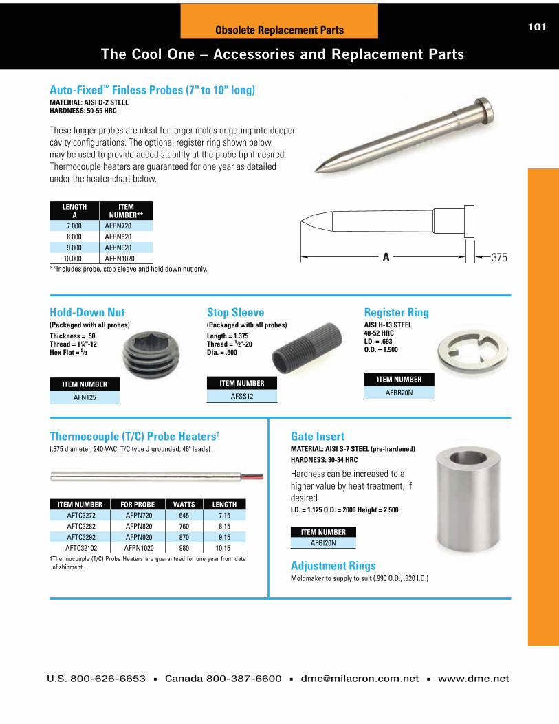
page content
text101
page content
101Obsolete Replacement Parts
U.S. 800-626-6653 Canada 800-387-6600 [email protected] www.dme.net
101Obsolete Replacement Parts
The Cool One – Accessories and Replacement Parts
Auto-Fixed™ Finless Probes (7" to 10" long)MATERIAL: AISI D-2 STEEL HARDNESS: 50-55 HRC
LENGTH A
ITEM NUMBER**
7.000 AFPN7208.000 AFPN8209.000 AFPN920
10.000 AFPN1020**Includes probe, stop sleeve and hold down nut only.
Gate InsertMATERIAL: AISI S-7 STEEL (pre-hardened)HARDNESS: 30-34 HRC
Hardness can be increased to a
higher value by heat treatment, if
desired.I.D. = 1.125 O.D. = 2000 Height = 2.500
ITEM NUMBERAFGI20N
Thermocouple (T/C) Probe Heaters†
(.375 diameter, 240 VAC, T/C type J grounded, 46" leads)
ITEM NUMBER FOR PROBE WATTS LENGTHAFTC3272 AFPN720 645 7.15AFTC3282 AFPN820 760 8.15AFTC3292 AFPN920 870 9.15
AFTC32102 AFPN1020 980 10.15† Thermocouple (T/C) Probe Heaters are guaranteed for one year from date
of shipment. Adjustment RingsMoldmaker to supply to suit (.990 O.D., .820 I.D.)
These longer probes are ideal for larger molds or gating into deeper
cavity configurations. The optional register ring shown below
may be used to provide added stability at the probe tip if desired.
Thermocouple heaters are guaranteed for one year as detailed
under the heater chart below.
A .375
Hold-Down Nut(Packaged with all probes)Thickness = .50 Thread = 1¼"-12 Hex Flat = 5⁄8
ITEM NUMBER
AFN125
Stop Sleeve(Packaged with all probes)Length = 1.375 Thread = 1⁄2"-20 Dia. = .500
ITEM NUMBER
AFSS12
Register RingAISI H-13 STEEL 48-52 HRC I.D. = .693 O.D. = 1.500
ITEM NUMBER
AFRR20N

U.S. 800-626-6653 Canada 800-387-6600 [email protected] www.milacron.com
102102 Hot Runner Systems
Ho
t R
un
ner
Syste
ms
|
Mod
ular
Com
pone
nts
Del
iver
Hig
h-Pe
rfor
man
ce S
olut
ions
Modular Components Deliver High-Performance Solutions
Today’s increasingly feature-packed plastic products benefit tremen-
dously from the right hot runner solution. Increasing resin costs and
the complexity of engineered materials only compound this challenge.
From hot sprue bushings to turnkey hot halves, DME offers a wide
range of solutions to almost any molding application.
Get the modular advantage with DME hot runner systems DME’s newest family of hot runner systems are built on an architec-
ture of modular components so we can quickly custom configure a
system that is ideal for your application. With the tremendous time
pressures on moldmakers today, our modular architecture enables
industry-leading delivery times. This modular approach shortens
delivery, improves cost-effectiveness and optimizes performance.
DME’s Meteor and Stellar hot runner systems offer standardized
products, custom-configured to each application in only a few days.
Our dedicated team of application engineers works to understand the critical variables of your molding equation.
Here are a few areas in which our global capabilities make hot runner
solutions more efficient and more economical.
Micromolding solutionsAs plastic parts get smaller and more complex, micromolding solutions
become more challenging. DME Stellar Hot Runner Systems were
designed for the demands of very small part molding with engineered
or commodity materials. The Stellar hot runner system is available for
applications with center-to-center dimensions as close as 17mm.
Application engineered solutionsAs an industry leader in hot runner systems, DME is able to offer our
customers a comprehensive resource for hot runner solutions. Our
dedicated team of application engineers works to understand the
critical variables of your molding equation and engineer a hot runner
system solution that is optimal for your project.
Powerful custom manufacturing capabilitiesFor more complex, custom and even high cavitation applications,
DME offers extensive manufacturing capabilities enabling complete,
custom solutions. For example, turnkey hot half systems — fully
assembled, wired, and electrically tested — are ready to drop in
with no machining and minimal installation demands.

DME CONTROL SYSTEMS

U.S. 800-626-6653 Canada 800-387-6600 [email protected] www.dme.net
TSP and TSP Plus Temperature Control System ........................................105-110Touch Screen Panel, Powerful, flexible and affordable
Go to www.dme.net/prices for the latest pricing guide.Online Price Guide
Table of Contents
104 Control Systems
Valve Gate Controls ................................156-162Energy efficient, reliable and compact hydraulic and pneumatic controls
Smart Series® Temperature Control Systems ..................................111 to 155RoHS/WEEE-compliant temperature controls for hot runner systems
Technical Support ..................................163-164Customer power requirement worksheet Breaker wattage size tableControl system repairs and returns

Smart Series® TSP™
Temperature Control System Series
POWERFUL, FLEXIBLE
AND AFFORDABLE

106
U.S. 800-626-6653 Canada 800-387-6600 [email protected] www.dme.net
TSP Features and Benefits
TSP Temperature Control SystemT
SP
Tem
pera
ture
Co
ntr
ol S
yste
m |
T
SP
Fea
ture
s an
d Be
nefit
s
Benefits
TSP USER-FRIENDLY PERFORMANCE
■ Intuitive, leading edge touch screen display with adjustable viewing angle■ Automatically employed diagnostics to ensure optimal hardware configuration
and performance■ Advanced micro controller technology■ Continuous ground fault and current measurement
PLUG-AND-PLAY SYSTEM ARCHITECTURE
■ Patented “all-in-one” control card designed for reliability■ Modular 6-zone cards; 15 amps per zone■ Field calibration mode■ Universal power supply
OPTIMIZES PERFORMANCE FOR ALL HOT RUNNER SYSTEMS
■ Unique low voltage soft-start feature maximizes heater life■ Uniform startup feature reduces scrap and energy usage■ Proprietary adaptive auto-tuning control algorithm■ Phase angle or burst firing modes (time proportional, zero-crossing)
ROBUST, HIGH-QUALITY DESIGN
■ Compact solid metal enclosure with heavy-duty industrial connectors■ Mold and controller protection features■ On-board heater and thermocouple fuses■ Portable stand available
OPTIONAL 7" DISPLAY WITH ADVANCED FEATURE SET NOW AVAILABLE!
The TSP™ Temperature Control System optimizes injection molding performance of any hot runner system with the advanced features of a touch screen unit but within a minimal footprint.
IMPORTANT NOTICE: TSP Controllers are not designed to control all zones as manifold zones. Doing so will cause the main circuit breaker to trip.

U.S. 800-626-6653 Canada 800-387-6600 [email protected] www.dme.net
text107
TS
P Te
mp
era
ture
Co
ntro
l Syste
m | T
SP
SpecificationsTSP Temperature Control System
TSP Specifications
Specifications
ITEM NUMBER SLOTS # OF ZONES AVAILABILITY
ITS-06-15 1 6 Special order; contact DME
ITS-12-15 2 12 In stock
ITS-18-15 3 18 Special order; contact DME
ITS-24-15 4 24 In stock
ITS-30-15 5 30 Special order; contact DME
ITS-36-15 6 36 Special order; contact DME
ITS-42-15 7 42 Special order; contact DME
ITS-48-15 8 48 In stock
TSP™ TEMPERATURE CONTROL SYSTEM SPECIFICATIONSUser Interface Full-color LCD touch screen on all HMI models
Display Size 5.7" QVGA
Calibration Accuracy 0.5˚C / 1˚F
Control Accuracy +/- 0.5˚C / 1˚F
Power Response Time 8.3 ms at 60 Hz
Control Algorithm Adaptive PID 2 with auto-tuning
Degree (F or C) Software selectable
Thermocouple J- or K-Type, software selectable
Operating Range 0 - 472˚C or 32 - 882˚F
Output Voltage Maximum 264 VAC
Supply Voltage 200/240 Delta or 380/440V 3Ø Star
Supply Breaker 40A 3-phase breaker for 6- and 12-zone control units 63A 3-phase breaker for 18- to 48-zone control units
Frequency 50 - 60 Hz automatic switching
Ambient Temperature Range 5 - 45˚C (41 - 113˚F)
Humidity Range Up to 95% non-condensing
Ground Fault Detection 40mA per zone
Power Control Phase angle or burst firing modes (time proportional, zero-crossing)
Overload Protection Semi-conductor fuses on both heater legs
Control Modes Closed loop (auto), open loop (manual), standby, boost mode and slave mode
Alarm Output Closing contact relay, max. 5A, 230V
T/C and Power Connector HAN 24e or 3
LED Indicators Fault, Scan
Soft-Start with Auto-Tune Unique low voltage method for heater safety
Input Protection Plug-in nano fuses on both TC legs
Port (optional) USB

Co
ntr
ol S
yste
ms |
bl
ank
U.S. 800-626-6653 Canada 800-387-6600 [email protected] www.dme.net
108 text
text
PTC12TBTS
PTC12TBTS
PTC12TBTS
TS
P T
em
pera
ture
Co
ntr
ol S
yste
m |
T
SP
Com
pone
nt O
rder
ing
Info
rmat
ion
TSP Component Ordering Information
TSP Temperature Control System108
MPC12C10G
TC12C10G
Mold Power Cables (15 AMP Max)ITEM
NUMBERITEM
NUMBERITEM
NUMBERNUMBER OF ZONES
(MAX.)
FROM 15 AMP FRAME (S)
TO POWER INPUT CONNECTOR
10 FOOT LONG 20 FOOT LONG 30 FOOT LONG FOR CONNECTIONS
MPC12C10G MPC12C20G MPC12C30G 12 12 ZONE PIC12G
Thermocouple Cables (for 15 or 30 AMP Mainframes)ITEM
NUMBERITEM
NUMBERITEM
NUMBERNUMBER OF ZONES
(MAX.)
FROM 15 AMP FRAME (S)
TO THERMOCOUPLE CONNECTOR
10 FOOT LONG 20 FOOT LONG 30 FOOT LONG FOR CONNECTIONS
TC12C10G TC12C20G TC12C30G 12 12 ZONE MTC12G
TO FRAME TO MOLD
TO FRAME TO MOLD
ZONES CONTROLLER CABLES TERMINAL MOUNTING BOX
12 ZONES OF CONTROL
(15 AMP)
24 ZONES OF CONTROL
(15 AMP)
48 ZONES OF CONTROL
(15 AMP)
MPC12C10G
TC12C10G
(1 each)
(2 each)
+ +
+ +
+ +
MPC12C10G
TC12C10G
(2 each)
MPC12C10G
TC12C10G
(4 each)
(1 each)
(4 each)
ITS-12-15
ITS-24-15
ITS-48-15
RPM0124
Module Replacement Fuses (sold in packs of 5)
ITEM NUMBER DESCRIPTION AMPS
RPM0123 POWER FUSE 15
RPM0124 TC FUSE .062
ITEM
ITSTROLLEY

U.S. 800-626-6653 Canada 800-387-6600 [email protected] www.dme.net
109
TSP Plus Temperature Control System
TSP Temperature Control System SeriesT
SP
Tem
pera
ture
Co
ntro
l Syste
m | TSP Plus
Everything you loved about the original TSP controller with new enhanced features for optimal control.
Automatic Leak detectionEnhanced 7” Color Touch screen Storage : up to 100 Tools Full IO function card with 4 input + 4 output for communication Optional Thermocouple to monitor steel temperature and alarm if cooling is offAccuracy 0.01 oF Ability to control Small Mass / High Watt density nozzles Field selectable PID (parameters) to optimize control process APS technology (Adaptive Process System) SPI communication Protocol via RS232/RS485 included
SMART SERIES USER-FRIENDLY PERFORMANCE
PLUG-AND-PLAY SYSTEM ARCHITECTURE
OPTIMIZES PERFORMANCE FOR ALL HOT RUNNER SYSTEMS
ROBUST, HIGH-QUALITY DESIGN
7”
ITEM NUMBER SLOTS # OF ZONES
ITSP-12-15 2 12ITSP-24-15 4 24ITSP-48-15 8 48
IMPORTANT NOTICE: Smart Series Controllers are not designed to control all zones as manifold zones. Doing so will cause the main circuit breaker to trip.
See reverse side for accessories
ITEM NUMBER DESCRIPTION
ITSCGR-A PCB replacement card, 6 zones @ 15 AMP
Custom zone configurations available upon request

Co
ntr
ol S
yste
ms |
bl
ank
U.S. 800-626-6653 Canada 800-387-6600 [email protected] www.dme.net
110 text
text
PTC12TBTS
PTC12TBTS
PTC12TBTS
TS
P T
em
pera
ture
Co
ntr
ol S
yste
m |
TS
P Pl
us
TSP Plus Component Ordering Information
TSP Temperature Control System110
MPC12C10G
TC12C10G
Mold Power Cables (15 AMP Max)ITEM
NUMBERITEM
NUMBERITEM
NUMBERNUMBER OF ZONES
(MAX.)
FROM 15 AMP FRAME (S)
TO POWER INPUT CONNECTOR
10 FOOT LONG 20 FOOT LONG 30 FOOT LONG FOR CONNECTIONS
MPC12C10G MPC12C20G MPC12C30G 12 12 ZONE PIC12G
Thermocouple Cables (for 15 or 30 AMP Mainframes)ITEM
NUMBERITEM
NUMBERITEM
NUMBERNUMBER OF ZONES
(MAX.)
FROM 15 AMP FRAME (S)
TO THERMOCOUPLE CONNECTOR
10 FOOT LONG 20 FOOT LONG 30 FOOT LONG FOR CONNECTIONS
TC12C10G TC12C20G TC12C30G 12 12 ZONE MTC12G
TO FRAME TO MOLD
TO FRAME TO MOLD
ZONES CONTROLLER CABLES TERMINAL MOUNTING BOX
12 ZONES OF CONTROL
(15 AMP)
24 ZONES OF CONTROL
(15 AMP)
48 ZONES OF CONTROL
(15 AMP)
MPC12C10G
TC12C10G
(1 each)
(2 each)
+ +
+ +
+ +
MPC12C10G
TC12C10G
(2 each)
MPC12C10G
TC12C10G
(4 each)
(1 each)
(4 each)
ITSP-12-15
ITSP-24-15
ITSP-48-15
RPM0124
Module Replacement Fuses (sold in packs of 5)
ITEM NUMBER DESCRIPTION AMPS
RPM0123 POWER FUSE 15
RPM0124 TC FUSE .062
ITEM
ITSPTROLLEY
ITEM
ITSPALRMLT

Smart Series®
ROHS/WEEE-COMPLIANT
TEMPERATURE CONTROLS
FOR HOT RUNNER SYSTEMS

112
U.S. 800-626-6653 Canada 800-387-6600 [email protected] www.dme.net
RoHS/WEEE CompliantAdvanced Temperature Control for Hot Runner Systems
Smart Series®S
ma
rt S
eri
es
®
|
Adva
nced
Tem
pera
ture
Con
trol
for H
ot R
unne
r Sys
tem
s
Capability/RoHS and WEEE Compliant
Two-Year Warranty
Electrical Noise Immunity
®
Heavy Duty Welded Construction

113
U.S. 800-626-6653 Canada 800-387-6600 [email protected] www.dme.net
Control ModulesSSM (15 and 30 AMP): ®
DSS (15 and 30 AMP):
Accessory ModulesTAS:
NOTE:
Simplified Power Hook-UpConcern for user convenience didn’t stop with improved operation features. DME went one step beyond to ensure that the power hook-up procedure goes smoothly as well. For this reason, detailed schematics for various hook-ups are provided directly on all mainframe back panels. If it is ever necessary to change the configuration, these diagrams will help ensure safe and proper connections. All wiring diagrams can be referenced at the end of this section.
SSH Controller (10 AMP)
Smart Series®
CE COMPLIANT! DME Mainframes and Modules comply with Electromagnetic compatibility and low voltage directives
Sm
art S
erie
s® | CE CO
MPLIAN
T! Control Modules
SSM1512
DSS1512
SSH1022

114
U.S. 800-626-6653 Canada 800-387-6600 [email protected] www.dme.net
Sm
art
Seri
es
® |
Sm
art S
erie
s® T
empe
ratu
re C
ontr
ol S
yste
ms
Smart Series® Temperature Control Systems
Smart Series®
Mainframe
Circuit Breaker/Disconnect
Mold Power Cable
Thermocouple Cable
Mold Power Input Connector
Insulated Crimp Connector
Thermocouple Connector
Terminal Mounting Boxes
Mainframe Blank Panels
Module Replacement Fuses
Control ModulesTABLE OF CONTENTS PAGEIntroduction ................................................................................................................................ 112-113
Typical System Configurations .......................................................................................................115
SSH Single Zone Controller ..................................................................................................... 116-117
Single and Two-Zone Mainframes and Accessories .......................................................... 118-121
Single Zone High Power Mainframes ............................................................................................121
Smart Series Mainframes ........................................................................................................ 122-124
Digital Current / Voltage Monitor ...................................................................................................125
Smart Series Accessories ...............................................................................................................126
Standard Mainframe Connector Wiring ........................................................................................127
Wiring Diagram for Hot Runner Molding System and Smart Series / G-Series Mold Connectors .........................................................................128
Wiring Diagram for Hot Runner Molding System and High Power Smart Series / G-Series Mold Connectors ...................................................129
Cables and Connector Kits ...................................................................................................... 131-132
Mold Connector Pocket Layouts ............................................................................................ 133-134
Terminal Mounting Boxes ........................................................................................................ 135-136
SSM Temperature Control Modules ...................................................................................... 137-138
DSS Temperature Control Modules ....................................................................................... 139-140
TSM Temperature Control Module with Color Touch Screen ........................................... 141-142
TAS Temperature Alarm / Standby Heat Modules .............................................................. 143-144
Replacement Parts and Service Items .................................................................................. 145-147
Input Power Wiring Diagrams ................................................................................................ 148-150
Alternate Cable Configuration ................................................................................................ 151-153
Terminal Box Detail & Mold Connectors – European .................................................................154
Cable Storage Basket.......................................................................................................................155
1
2
3
4
5
6
7
8
9
10
11
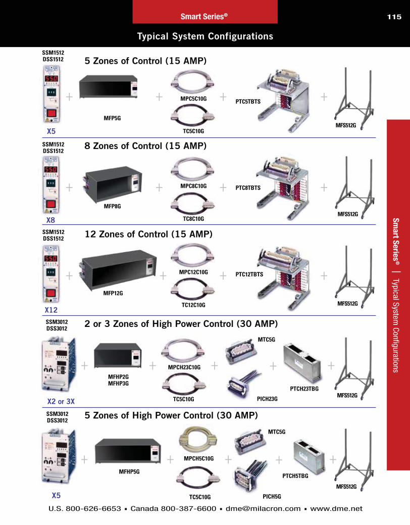
115
U.S. 800-626-6653 Canada 800-387-6600 [email protected] www.dme.net
Sm
art S
erie
s® | Typical System
Configurations
Typical System Configurations
Smart Series®
MFS512G
MFS512G
MFS512G
MFS512G
PTC12TBTS
PTC8TBTS
PTC5TBTS
5 Zones of Control (15 AMP)
X5
MFP5G
TC5C10G
MPC5C10G
SSM1512DSS1512
X5
SSM3012DSS3012
X8
SSM1512DSS1512
SSM1512DSS1512
MFP8G
TC8C10G
MPC8C10G
MFP12G
TC12C10G
MPC12C10G
MFHP2GMFHP3G
TC5C10G
MPCH23C10G
MTC5G
MTC5G
PTCH23TBG
MFHP5G
TC5C10G
MPCH5C10G
PTCH5TBG
PICH5G
PICH23G
5 Zones of High Power Control (30 AMP)
2 or 3 Zones of High Power Control (30 AMP)
12 Zones of Control (15 AMP)
8 Zones of Control (15 AMP)
MFS512G
X12
SSM3012DSS3012
X2 or 3X
+ + + +
+ + + +
+ + + +
+ + + ++
+ + + ++

116
U.S. 800-626-6653 Canada 800-387-6600 [email protected] www.dme.net
Smart Series®
RoHS/WEEE CompliantSmart Series® Single Zone Temperature Controller
Sm
art
Seri
es
® |
Sm
art S
erie
s Si
ngle
Zon
e Te
mpe
ratu
re C
ontr
olle
r
Key FeaturesLarge Digital Display
-Setpoint Pushwheel
AUTO % Power Display
Switchable OptionsShorted Thermocouple Sensitivity Adjustment
Switchable °C/°F Operation
K Type Thermocouple SupportCut Feature
BACKWARDTHERMOCOUPLE
TEMP MODEFAHRENHEIT
TEMP MODECENTIGRADE
PROCESSTEMP
MANUAL% POWER
FRONT PANELLOCKOUT
LOCKOUTERROR
SHORTEDTHERMOCOUPLE
OPENTHERMOCOUPLE
BUMPLESSTRANSFER
Front Panel Digital LED Indicators
SSH1022/21 (10 AMP)
or a machine nozzle
Operational RefinementsImproved SmartStart®
®
SelectiveCycle®
Bumpless Transfer
Third Fuse

117
U.S. 800-626-6653 Canada 800-387-6600 [email protected] www.dme.net
Smart Series®
RoHS/WEEE CompliantSmart Series® Single Zone Temperature Controller
Sm
art S
erie
s® | Sm
art Series Single Zone Temperature Controller
Warranty: Two year (excluding triac and fuses).
Front Panel Controls and Indicators1. Process Temperature Display:
2. Temperature Deviation Lights:
3. Auto / Manual / % Auto Power Switch:
4. LED Mode Indicators:
®
5. Setpoint Pushwheel:
6. Power On/Off Switch:
1. Mold Power and Thermocouple Output Connector:
2. Power Input Cord:
3. Load Fuse Receptacles:
Rear Panel
* ITEMS ORDERED SEPARATELY
SSH1022/21 (10 AMP)
1
3
2
35
21
6
4
CONTROLLERITEM NUMBER
VOLTS (VAC)
SSH1022 240
SSH1021 120
CABLE*ITEM NUMBER
LENGTH(FEET)
MPTC10 10
MPTC20 20
MOLD POWER ANDTHERMOCOUPLE CONNECTOR*
ITEM NUMBER
CKPTIC1
CKPTM1INCLUDED
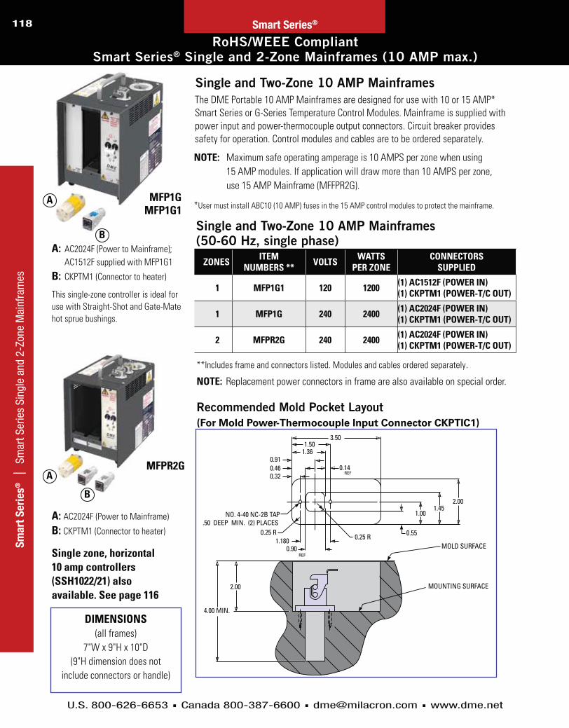
118
U.S. 800-626-6653 Canada 800-387-6600 [email protected] www.dme.net
Sm
art
Seri
es
® |
Sm
art S
erie
s Si
ngle
and
2-Z
one
Mai
nfra
mes
RoHS/WEEE CompliantSmart Series® Single and 2-Zone Mainframes (10 AMP max.)
Smart Series®
Single and Two-Zone 10 AMP Mainframes
Recommended Mold Pocket Layout(For Mold Power-Thermocouple Input Connector CKPTIC1)
Single and Two-Zone 10 AMP Mainframes(50-60 Hz, single phase)
NOTE:
.
NOTE:
DIMENSIONS
A: B:
A:
B:
MFP1GMFP1G1
MFPR2G
Single zone, horizontal 10 amp controllers (SSH1022/21) also available. See page 116
A
B
A
B
ZONES ITEM NUMBERS ** VOLTS WATTS
PER ZONECONNECTORS
SUPPLIED
1 MFP1G1 120 1200 (1) AC1512F (POWER IN)(1) CKPTM1 (POWER-T/C OUT)
1 MFP1G 240 2400 (1) AC2024F (POWER IN)(1) CKPTM1 (POWER-T/C OUT)
2 MFPR2G 240 2400 (1) AC2024F (POWER IN)(1) CKPTM1 (POWER-T/C OUT)

119
U.S. 800-626-6653 Canada 800-387-6600 [email protected] www.dme.net
ITEM NUMBER
CKPTF1
CKPTF1L
Smart Series®
RoHS/WEEE Compliant: Smart Series® Single and 2-Zone Mainframe Accessories (10 AMP)
Sm
art S
erie
s® | Sm
art Series Single and 2-Zone Mainfram
e Accessories
Mold Power-Thermocouple Input Connector
Replacement Connector Kits (for Controller & Cables)
Armored Mold Power-Thermocouple Cables
AC1512F
AC2024F
CKPTM1
CKPTM1L
CKPTF1
CKPTF1L
MALE
1
23
45
W
B
-+
FEMALE
1
23
4
5
W
B
- +
MALE POWER – T/C CONNECTORS:
For Use With MFP1G, MFP1G1, MFPR2G, SSH1022 and SSH1021
PTC210
FEMALE POWER – T/C CONNECTORS:
ITEM NUMBER
PTC210
ITEM NUMBER
CKPTM1
CKPTM1L
ITEM NUMBER VOLTS
AC1512F 120
AC2024F 240
ITEM NUMBER
CKPTOC1
ITEMNUMBER
MPTC10
MPTC20
ITEMNUMBER
CKPTIC1
Terminal Mounting Boxes – Prewired (10 AMP) 5 Pin
ITEM NUMBER
PTC210TBGTS

120
U.S. 800-626-6653 Canada 800-387-6600 [email protected] www.dme.net
Sm
art
Seri
es
® |
Sm
art S
erie
s 2-
Zone
Mai
nfra
mes
and
Acc
esso
ries
Smart Series® 2-Zone Mainframes (15 AMP) and Accessories
Smart Series®
MFFPR2G
AC1524M M2MJAC1240F
Two-Zone 15 AMP Mainframes
NOTE:
FRAME DIMENSIONS:
TWO-ZONE 15 AMP MAINFRAME (240 VAC, 50-60 Hz, SINGLE PHASE)
Armored Mold Power –Thermocouple Cables (15 AMP)
Terminal Mounting Boxes –Prewired (15 AMP)
NOTE:
MFFPR2G
1240F
T
N
T
ITEM NUMBERPTC2TBGTS
ITEM NUMBER
PTC0110
PTC0120
ITEM NUMBERS DESCRIPTION
AC1240F* Female 240 VAC twist-lock power input connector(mates with male frame power input)
AC1524M* Male 240 VAC power output connector(mates with female frame power outputs)
M2MJ* Thermocouple mini-plug (mates with frame jack strip connector)
PTC2TBGTS 2 zone, pre-wired terminal mounting box with terminal strip(mounts to mold; mates with PTC0110 or PTC0129 cables)
ITEM NUMBER WATTS PER ZONE CONNECTORS SUPPLIED
MFFPR2G 3500(1) AC1240F (POWER IN)
(1) AC1524M (POWER OUT)(2) M2MJ (T/C IN)

121
U.S. 800-626-6653 Canada 800-387-6600 [email protected] www.dme.net
Smart Series®
Smart Series® Single Zone High Power Mainframes (30 AMP Max.)
Sm
art S
erie
s® | Sm
art Series Single Zone High Power M
ainframes
NOTE: Overall dimensions shown include allowances for hardware (assembly screws) but not connectors
AC1240MAC1240F
M2MJ
MFHP1G
Single Zone 30 AMP Mainframes (240 VAC, 50-60 Hz, Single Phase)
*Included with MFHP1G mainframe
FRAME DIMENSIONS:
TERMINAL MOUNTING BOXPTCH1TBG
D: TCS1E: AC1240MI
Replacement Connectors and Accessories
ED

122
U.S. 800-626-6653 Canada 800-387-6600 [email protected] www.dme.net
MOLD POWER CABLE (10, 20 OR 30 FOOT)
THERMOCOUPLE CABLE (10, 20 OR 30 FOOT)
Smart Series®
Smart Series® Mainframes (15 AMP)
Sm
art
Seri
es
® |
Sm
art S
erie
s® M
ainf
ram
es
Thermocoupleinput withretaining
latch
Power output with retaining
latch
WIDTH (W)
12"
9"
Main AC powerinput strain reliefCooling Fan
Smart Series® Mainframe (15 AMP Max.) Configurations
ITEM NUMBER W*
WORLDWIDE WIRING CAPABILITIES
These wiring adjustments can be performed in the field to suit the requirements of the application. If specified at the time of original order, DME will supply the Mainframe required.
NOTE:

123
U.S. 800-626-6653 Canada 800-387-6600 [email protected] www.dme.net
Sm
art S
erie
s® | Sm
art Series® M
ainframes
Smart Series® Mainframes (15 AMP)
Smart Series®
NOTES:
SMART SERIES MAINFRAMES Optional Current Voltage Monitor
is Factory Installed in CV-Style Frames
CABLES AND MOLD CONNECTORS REQUIRED (Not included with Mainframes and Must be Ordered Separately)
Z O N E S
“MFP” TYPE FOR TEMP. AND
POWER CONTROL
“MFP” TYPE WITH CURRENT VOLTAGE
MONITOR
“MFCP” TYPE FOR TEMP. CONTROL AND COMMUNICATIONS
“MFCP” TYPE WITH CURRENT VOLTAGE
MONITOR
MOLD POWER CABLES C10=10 FT. C20=20 FT. C30=30 FT.
(SELECT LENGTH DESIRED)
THERMOCOUPLE CABLES C10=10 FT. C20=20 FT. C30=30 FT.
(SELECT LENGTH DESIRED)
MOLD POWER INPUT CONNECTORS (INCL.
CRIMP CONNECTORS)
THERMOCOUPLE CONNECTORS
ITEM NUMBER
ITEM NUMBER (CV-STYLE)
ITEM NUMBER
ITEM NUMBER (CV-STYLE) QTY. ITEM
NUMBER QTY. ITEM NUMBER QTY. ITEM
NUMBER QTY. ITEM NUMBER
5
8
12
16
20
24
28
32
36
40
44
48
and and and and
and and and and
and and and and
and and and and
and and and and
NOTE:
Terminal Mounting Boxes
Z O N E S
ORDER ITEMS A and B or C(A)
FOR POWER INPUT CONNECTORS
(B) FOR THERMOCOUPLE CABLES
CONNECTORS
(C) COMBINATION POWER & TC
QTY. ITEM NUMBER QTY. ITEM
NUMBER QTY. ITEM NUMBER
5
8
12
16
20
24
28 and and
and and
Z O N E S
ORDER ITEMS A and B or C(A)
FOR POWER INPUT CONNECTORS
(B) FOR THERMOCOUPLE CABLES
CONNECTORS
(C) COMBINATION POWER & TC
QTY. ITEM NUMBER QTY. ITEM
NUMBER QTY. ITEM NUMBER
32
36
40
44
48
and and
and and
and and

124
U.S. 800-626-6653 Canada 800-387-6600 [email protected] www.dme.net
Smart Series®
Smart Series® High Power Mainframes (30 AMP)
Sm
art
Seri
es
® |
Sm
art S
erie
s® H
igh
Pow
er M
ainf
ram
es
HIGH POWER MOLD POWER CABLE (10, 20 OR 30 FOOT)
THERMOCOUPLE CABLE (10, 20 OR 30 FOOT)(USE 5-ZONE CABLE) HIGH POWER
MOLD POWERINPUT CONNECTOR
INSULATEDCRIMPCONNECTORS(INCLUDED WITHMOLD POWERINPUTCONNECTOR)
MAINFRAME WITH CIRCUIT BREAKER DISCONNECT IS STANDARD; CURRENT
VOLTAGE MONITOR IS OPTIONAL
THERMOCOUPLE CONNECTOR
TERMINAL MOUNTING BOX (OPTIONAL)
50 AMP 3-PHASECIRCUIT BREAKER
9"
(14 3/16" WIDE)
50 AMP 3-PHASECIRCUIT BREAKER
9"
(20 3/16" WIDE)
70 AMP 3-PHASECIRCUIT BREAKER
(28 3/16" WIDE)
9"
NOTE:
SMART SERIES HIGH POWER MAINFRAMES Optional Current Voltage Monitor is Factory Installed in CV-Style Frames
Z O N E S
“MFHP” TYPE FOR TEMP. CONTROL
“MFHP” TYPE WITH CURRENT VOLTAGE MONITOR
“MFCHP” TYPE FOR TEMP. CONTROL AND COMMUNICATIONS
“MFCHP” TYPE WITH CURRENT VOLTAGE MONITOR
ITEM NUMBER
ITEM NUMBER (CV-STYLE)
ITEM NUMBER
ITEM NUMBER (CV-STYLE)
2
3
5
CABLES AND MOLD CONNECTORS REQUIRED (Not included with Mainframes and Must be Ordered Separately)
Z O N E S
MOLD POWER CABLES C10=10 FT. C20=20 FT. C30=30 FT.
(SELECT LENGTH DESIRED)
THERMOCOUPLE CABLES C10=10 FT. C20=20 FT. C30=30 FT.
(SELECT LENGTH DESIRED)
MOLD POWER INPUT CONNECTORS
(INCL. CRIMP CONNECTORS)
THERMOCOUPLE CONNECTORS
QTY. ITEM NUMBER QTY. ITEM
NUMBER QTY. ITEM NUMBER QTY. ITEM
NUMBER
2
3
5
Terminal Mounting Boxes
Z O N E S
ORDER ITEMS A and B or C(A)
FOR POWER INPUT CONNECTORS(B)
FOR THERMOCOUPLE CABLES CONNECTORS(C)
COMBINATION POWER & TC
QTY. ITEM NUMBER QTY. ITEM
NUMBER QTY. ITEM NUMBER
2
3
4
NOTE:
NOTE:
NOTE:
DIMENSIONS ABOVE DO NOT INCLUDE CONNECTORS

125
U.S. 800-626-6653 Canada 800-387-6600 [email protected] www.dme.net
Sm
art S
erie
s® | Sm
art Series® D
igital Current/Voltage Monitor
Smart Series® Digital Current/Voltage Monitor
Smart Series®
3
4
5
2
1
NOTE:
See pages 123 and 124 for appropriate mainframe item numbers.
Streamlined Design For Improved Performance
Current Supply To Each Zone
Input Voltage From Each Phase
1. CIRCUIT BREAKER/DISCONNECT –
2. POWER ON LIGHT (amber) –
3. AMPS/VOLTS METER –
4. AMPS/VOLTS INDICATOR –
5. SELECTOR SWITCH –
SpecificationsVoltmeter Range
Voltmeter Accuracy
Maximum Voltmeter Input
Input Voltage Ammeter Range A
Ammeter Accuracy
Maximum Ammeter Input

126
U.S. 800-626-6653 Canada 800-387-6600 [email protected] www.dme.net
28 1/4
Smart Series®
Smart Series® Accessories
Sm
art
Seri
es
® |
Sm
art S
erie
s® A
cces
sorie
s
3 SECTIONS
4 SECTIONS
2 SECTIONS
46"
25 3/4"
1 SECTIONS
Step-Down Transformer Kits (from 480 VAC to 240 VAC)
NOTE:
Also Available:
NOTE:
Insulated Crimp Connectors
Universal Floor Stand
Module Replacement Fuses (sold in packages of 5)
ITEM NUMBER RATING
ITEM NUMBER RATING
ITEM NUMBER AMPS RATING
Mainframe Blank Panels
MFBP10G
AMP
MFBP30G AMP
AMP
ITEM NUMBER
ITEM NUMBER AMPS

127
U.S. 800-626-6653 Canada 800-387-6600 [email protected] www.dme.net
Smart Series®
Smart Series® Mainframe Connector Wiring
Sm
art S
erie
s® | Sm
art Series® M
ainframe Connector W
iring
SIDE OF MAINFRAME
High Power Mainframe Connector Wiring
SIDE OF MAINFRAME
Standard Mainframe Connector Wiring

128
U.S. 800-626-6653 Canada 800-387-6600 [email protected] www.dme.net
Sm
art
Seri
es
®
|
Wiri
ng D
iagr
am w
ith S
mar
t Ser
ies®
Mol
d Co
nnec
tors
Wiring Diagram for DME Hot Runner Molding System with Smart Series® Mold Connectors
Smart Series®
BLAC
K (+
)W
HITE
(-)
BLK
BLK
BLK
BETW
EEN
BLK
& W
HITE
LEA
DS.
CHEC
K CO
NN
ECTI
ONS
OF B
LACK
NO
TES:

129
U.S. 800-626-6653 Canada 800-387-6600 [email protected] www.dme.net
Smart Series®
Wiring Diagram for DME Hot Runner Molding System with High Power Smart Series® Mold Connectors
Sm
art S
erie
s® | W
iring Diagram
with High Pow
er Smart Series
® Mold Connectors
BLAC
K (+
)
WHI
TE (-
)
BLAC
KW
HITE
CHEC
K CO
NN
ECTI
ONS
OF B
LACK
AN
D W
HITE
LEA
DS T
O EN
SURE
USE
OHM
MET
ER T
O M
EASU
RE B
ETW
EEN
F BL
ACK
AND
WHI
TE L
EADS
.
NO
TES:

130
U.S. 800-626-6653 Canada 800-387-6600 [email protected] www.dme.net
Smart Series®
Mold Power and Thermocouple Cables
MPC12C10G
TC12C10G
Sm
art
Seri
es
® |
M
old
Pow
er a
nd T
herm
ocou
ple
Cabl
es
Universal Mold Power Cable (15 AMP)
Thermocouple Cables (for use with 15 or 30 AMP Mainframes)
SPECIAL CABLES
Mold Power Cables (15 AMP Max)10 FOOT LONG 20 FOOT LONG 30 FOOT LONG NUMBER
OF ZONES (MAX.)
FOR CONNECTIONS
ITEM NUMBER
ITEM NUMBER
ITEM NUMBER
FROM 15 AMP FRAME (S)
TO POWER INPUT CONNECTOR
Mold Power Cables (30 AMP Max)10 FOOT LONG 20 FOOT LONG
NUMBER OF ZONES (MAX.)
FOR CONNECTIONS
ITEM NUMBER
ITEM NUMBER
FROM 30 AMP FRAME (S)
TO POWER INPUT CONNECTOR
Thermocouple Cables10 FOOT LONG 20 FOOT LONG 30 FOOT LONG NUMBER
OF ZONES (MAX.)
FOR CONNECTIONS
ITEM NUMBER
ITEM NUMBER
ITEM NUMBER
FROM 15 AMP FRAME (S)
TO THERMOCOUPLE CONNECTOR

131
U.S. 800-626-6653 Canada 800-387-6600 [email protected] www.dme.net
PIC5G
PIC8G
PIC12G
For 30 AMP Applications
PICH23G
PICH5G
Smart Series®
RoHS/WEEE Compliant: Mold Power Input Connectors
Sm
art S
erie
s® | M
old Power Input Connectors
Mold Power Input Connectors
Insulated Crimp Connectors
NOTES:
.
NOTE:
NOTE:
NOTE:
NOTE:
For 15 AMP Applications

132
U.S. 800-626-6653 Canada 800-387-6600 [email protected] www.dme.net
Smart Series®
RoHS/WEEE Compliant: Mold Thermocouple Connectors
Sm
art
Seri
es
® |
M
old
Ther
moc
oupl
e Co
nnec
tors
MTC12G
TPC0001
MTC8G
MTC5G
MOLD THERMOCOUPLE CONNECTOR MTC5GMTC8GMTC12G
MOLD POWER AND THERMOCOUPLE CONNECTOR TPC0001
NOTE:

133
U.S. 800-626-6653 Canada 800-387-6600 [email protected] www.dme.net
Smart Series®S
ma
rt Serie
s® | M
old Connector Pocket Layouts
Mold Connector Pocket Layouts
NOTE:
NOTE:
NOTE:

134
U.S. 800-626-6653 Canada 800-387-6600 [email protected] www.dme.net
Smart Series®
Mold Connector Pocket Layouts
Sm
art
Seri
es
® |
M
old
Conn
ecto
r Poc
ket L
ayou
ts
NOTE: mounting.

135
U.S. 800-626-6653 Canada 800-387-6600 [email protected] www.dme.net
Smart Series®
RoHS/WEEE Compliant: Terminal Mounting Boxes
Sm
art S
erie
s® | Term
inal Mounting Boxes
PTC12TBGTS
Pre-wired Combination Terminal Mounting Boxes
PTC5TBGTS
PTC210TBGTS
PTC12TBTSPTC8TBTSPTC5TBTS
PTC8TBGTS
Combination Terminal Mounting Boxes – with Terminal StripITEM NUMBER X Y H M1 M2 ACCEPTS

136
U.S. 800-626-6653 Canada 800-387-6600 [email protected] www.dme.net
Smart Series®
Terminal Mounting Boxes
Sm
art
Seri
es
® |
Te
rmin
al M
ount
ing
Boxe
s
NOTE: Overall dimensions shown include allowances for hardware (assembly screws) but not connectors
† Overall dimensions shown include allowances for hardware (assembly screws) but not connectors (example: For Item Number PTC0012 the “X” dimension is 4.29 not including screw heads)
†
†
†
* Used with 2-zone, 15 AMP mainframe MFFPR2G ** Used with 1-zone, 30 AMP mainframe MFHP1G
PIC512TBG
PTC0012
Terminal Mounting Boxes
PTC8TBG
PTC5TBG
PTC210

137
U.S. 800-626-6653 Canada 800-387-6600 [email protected] www.dme.net
Smart Series®
RoHS/WEEE Compliant: Microprocessor-Based Temperature Control Modules with Digital Display and Setpoint Pushwheel
Sm
art S
erie
s® | Control M
odules with D
igital Display
COMPATIBLE WITH TAS0512
ALARM AND SYSTEM CONTROL
FUNCTIONS. SEE PAGES 143-144.
SSM1512/11 (15 AMP) & SSM3012 (30 AMP)
NOTE:
Key Features
Setpoint Pushwheel
Operational RefinementsImproved SmartStart®
® SelectiveCycle®
Bumpless Transfer
Third Fuse
Anti-Arcing Feature
Switchable OptionsBoost, Idle and Power Off Features
Unique AutoBoost Option
Lights Out Feature
Shorted Thermocouple Sensitivity Adjustment
Switchable °C/°F Operation
K Type Thermocouple SupportCut Feature

138
U.S. 800-626-6653 Canada 800-387-6600 [email protected] www.dme.net
Sm
art
Seri
es
® |
Co
ntro
l Mod
ules
with
Dig
ital D
ispl
ay
RoHS/WEEE Compliant: Microprocessor-Based Temperature Control Modules with Digital Display and Setpoint Pushwheel
Smart Series®
Warranty:
Fuse Requirements (15 AMP only)
NOTE:
1. Process Temperature Display
2. Temperature Deviation Lights
3. Auto/Manual/Auto % Power Switch
4. LED Mode Indicators
®
5. Setpoint Pushwheel
6. Power On/Off Switch
Front Panel Controls and Indicators
Front Panel Digital LED Indicators
SSM1512SSM1511SSM3012
240120240
151530
360018007200
MODULEITEM NUMBER
VOLTAGE(VAC) AMPS WATTS
SSM1512/11 (15 AMP) & SSM3012 (30 AMP)
1
2
3
6
5
4

139
U.S. 800-626-6653 Canada 800-387-6600 [email protected] www.dme.net
Smart Series®
RoHS/WEEE Compliant: Microprocessor-Based Temperature Control Modules with Dual Digital Display
Sm
art S
erie
s® | Control M
odules with D
ual Digital D
isplay
®
® AMP
DSS1512/11 (15 AMP) & DSS3012 (30 AMP)
Front Panel Controls and Indicators
NOTE:
COMPATIBLE WITH TAS MODULE ALARM AND STANDBY HEAT FUNCTIONS. SEE PAGES 143-144.
1. Smart Start Light 2. Process Temperature Display 3. Temperature Deviation Lights
4. Setpoint Display 5. Auto/Manual Switch 6. Auto Light
7. Manual Light
8. 100% Power Switch 9. 100% Power Light 10. Up Arrow 11. Down Arrow 12. F1/F2 Lights 13. Power On/Off Switch
10
11
2
3
456
78
9
12
13
1
Front Panel Digital LED Indicators

140
U.S. 800-626-6653 Canada 800-387-6600 [email protected] www.dme.net
Sm
art
Seri
es
® |
Co
ntro
l Mod
ules
with
Dua
l Dig
ital D
ispl
ay
Microprocessor-Based Temperature Control Modules with Dual Digital Display
Smart Series®
DSS1512/11 (15 AMP) & DSS3012 (30 AMP)
Smart Series Microprocessor-Based Temperature Control Modules
ITEM NUMBER DSS1512 DSS3012
(240 VAC, standard)
AMPS 15 30
WATTS 3600 7200
(120 VAC, optional)ITEM NUMBER
DSS1511AMPS
15WATTS
1800
NOTE:
FOR °C OPERATION: FUSE REQUIREMENTS (15 AMP ONLY):
NOTE: WARRANTY:
Performance SpecificationsAuto and Manual Control Modes: ®
Temperature Range: Ambient to 999°F (537°C)Control Accuracy: Temperature Stability: Calibration Accuracy: Power Response Time: Manual Control: Smart Start®: Maximum Smart Start Duration: Smart Start Override Temperature: )100% Power: Operational Mode Priority: ®
Input SpecificationsThermocouple Sensor: External T/C Residence: .T/C Isolation: Cold Junction Compensation: T/C Break, Reversed & Shorted Protection: Input Impedance: Input Amplifier Stability: .Common Mode Rejection Ratio: Power Supply Rejection:
Output SpecificationsVoltage Power Capability:
Output Drive: Overload Protection:
Transient Protection: Power Line Isolation:
Controls and IndicatorsAuto/Manual Selection: Setpoint Adjustment: 100% Power Selection: Power On/Off: AMP AMP AMP approved.Setpoint Display: Process Display: 100% Power Indication: Auto Indication: Manual Indication: Smart Start Indication: Shorted T/C Indication: Opened T/C Indication: Reversed T/C Indication: Temperature Deviation Indicators:
Blown Fuse Indicators: AMP
Electrical Power SpecificationsInput Voltage: Frequency: DC Power Supplies: Module Power Usage: Dimensions:

141
U.S. 800-626-6653 Canada 800-387-6600 [email protected] www.dme.net
Smart Series®
RoHS/WEEE Compliant: Microprocessor-Based Temperature Control Modules with Color Touch Screen Display
Sm
art S
erie
s® | Control M
odules with Color Touch Screen D
isplay
TSM-15-12
®
®
TSM15 SmartSeries® Controller with Default Settings (Factory Settings)
Zone temperature 260ºC or 500ºFStandby level 100ºC or 180ºFBoost level 75ºC or 135ºFOver temperature range
10ºC or 18ºFUnder temperature rangeRamp OnAuto-Manual OnExtended alarms for Manual, Standby and Boost
Off
When reconfiguring your controller for a new tool or environment, this chapter of the manual shows how to alter controller default settings to your preferred values and afterward to save them.
2
1
3
4
Actual temperature (and scale)
Current mode shows set-point
Current reading
Percentage power applied
Front Panel Controls and Indicators

142S
ma
rt S
eri
es
® |
Co
ntro
l Mod
ules
with
Col
or T
ouch
Scr
een
Dis
play
U.S. 800-626-6653 Canada 800-387-6600 [email protected] www.dme.net
Smart Series®
RoHS/WEEE Compliant: Microprocessor-Based Temperature Control Modules with Color Touch Screen Display
Individual Card Diagnostics
The following is a list of alarm conditions that may be detected and which will also activate the output contacts.
ERROR MESSAGE CAUSE ACTION
ERR!
FUSE
GND
LINE
REV
T/C

143
U.S. 800-626-6653 Canada 800-387-6600 [email protected] www.dme.net
Sm
art S
erie
s® | Tem
perature Alarm/System
Control Modules
Temperature Alarm/System Control Modules
Smart Series®
Front Panel Controls and Indicators
1. Power On Indicator: 2. Audible Alarm:
3. Alarm Indicator: 4. Audio Alarm On/Off Switch: 5. Alarm Relay Connector
6. System Control Switch:
7. Power On/Off Switch: C
TAS0512/11 Temperature Alarm Function
System Control Functions
NORMAL / IDLE
BOOST / OFF
4
3
2
1
4
3
2
1
5
6
7

144
U.S. 800-626-6653 Canada 800-387-6600 [email protected] www.dme.net
Sm
art
Seri
es
® |
Te
mpe
ratu
re A
larm
/Sys
tem
Con
trol
Mod
ules
Temperature Alarm/System Control Modules
Smart Series®
NOTE:
FUSE REQUIREMENTS:
WARRANTY:
NOTE:
i
RemoteControl
Functions
Upgrade Kits For Converting to Communications Mainframes
ITEM NUMBER ITEM NUMBERMAIN FRAME MAIN FRAME
CIK4
CIK5
CIK7
CIK8
CIK11
CIK12
CIK16
CIK20
CIK24
4-ZONE
5-ZONE
7-ZONE
8-ZONE
11-ZONE
12-ZONE
16-ZONE
20-ZONE
24-ZONE
28-ZONE
32-ZONE
36-ZONE
40-ZONE
44-ZONE
48-ZONE
2-ZONE HIGH POWER
3-ZONE HIGH POWER
5-ZONE HIGH POWER
CIK28
CIK32
CIK36
CIK40
CIK44
CIK48
CIK2HP
CIK3HP
CIK5HP
TIME
BOOSTBOOST
NORMALNORMAL
AMBIENTOFF
IDLE93˚C (200˚F)
or100˚C (212˚F)
IDLE
TAS Module Compatibility
IDLEALARM OFFBOOSTMODULE
CSS1502/01 CSS3002 SSM15G SSM15G1 SSM30G
FUNCTIONS
ITEMNUMBER VOLTS
TAS0512
TAS0511
240 VAC
120 VAC
IDLEALARM OFFBOOSTSSM1502/01/12/11SSM3002/12DSS1502/01/12/11DSS3002/12TSM1512
FUNCTIONSMODULE

145
U.S. 800-626-6653 Canada 800-387-6600 [email protected] www.dme.net
Sm
art S
erie
s® | Replacem
ent Parts for Smart Series
® Temperature Control System
s
Replacement Parts and Service Items for DME Smart Series® Temperature Control Systems
Smart Series®
NOTE:
Connectors / Connector Kits (5-48 zone, 15 Amp; 2-5 zone, 30 Amp)
REFERENCE LETTER DESCRIPTION ITEM NUMBER
A
C
D
E
F
I

146
U.S. 800-626-6653 Canada 800-387-6600 [email protected] www.dme.net
Sm
art
Seri
es
®
|
Repl
acem
ent P
arts
for S
mar
t Ser
ies®
Tem
pera
ture
Con
trol
Sys
tem
s
Replacement Parts and Service Items for DME Smart Series® Temperature Control Systems
Smart Series®
Mainframe, Cable Components, and Service Tools*
*(Reference page 134-147 for Letter Designations)
CBD10MCBD20MCBD30MCBD50CBD70
PIN0114PIN0214PIN0120PIN0220
WHT1919RPM0048RPM0038RPM0044RPM0046RPM0059RPM0060RPM0061RPM0062RPM0063RPM0064RPM0065RPM0066RPM0067RPM0068RPM0069RPM0070RPM0071RPM0072RPM0073
SEE PREVIOUS PAGE
SEE PREVIOUS PAGE
SEE PREVIOUS PAGE
SEE PREVIOUS PAGE
SEE PREVIOUS PAGE
SEE PREVIOUS PAGE
SEE PREVIOUS PAGE
SEE PREVIOUS PAGE
SEE PREVIOUS PAGE
SEE PREVIOUS PAGE
SEE PREVIOUS PAGE
SEE PREVIOUS PAGE
SEE PREVIOUS PAGE
SEE PREVIOUS PAGE
SEE PREVIOUS PAGE
SEE PREVIOUS PAGE
SEE PREVIOUS PAGE
SEE PREVIOUS PAGE
SEE PREVIOUS PAGE
10 AMP 2 POLE, CIRCUIT BREAKER USED IN MFP1G AND MFP1G120 AMP 2 POLE, CIRCUIT BREAKER USED IN MFR2G30 AMP 2 POLE, CIRCUIT BREAKER USED IN MFFPR2G AND MFHP1G50 AMP 3 POLE, CIRCUIT BREAKER USED IN 5 THROUGH 12 ZONE MAINFRAMES70 AMP 3 POLE, CIRCUIT BREAKER USED IN 16 THROUGH 48 ZONE & HIGH POWER MAINFRAMES14 GAUGE MALE PIN FOR “B”& “F” POWER CONNECTORS (PACKAGE OF 30)14 GAUGE FEMALE SOCKET FOR “D”& “H” POWER CONNECTORS (PACKAGE OF 30)20 GAUGE MALE PIN FOR “G” THERMOCOUPLE CONNECTOR (PACKAGE OF 30)20 GAUGE FEMALE PIN FOR “E” THERMOCOUPLE CONNECTOR (PACKAGE OF 30)CRIMP TOOL FOR ALL PIN-XXXX LISTED ABOVEEXTRACTION TOOL FOR ALL PIN-TYPE CONNECTOR PINSNEON INDICATORS USED ON 240 VAC MAINFRAME CIRCUIT BREAKER PANELSCARD GUIDES FOR ALL MAINFRAMESPINS FOR WHITE EDGE CARD CONNECTORS “I” (PACKAGE OF 20)PANEL MOUNT BASE & LATCH FOR 5-ZONE THERMOCOUPLE MOLD CONNECTION “A”PANEL MOUNT BASE & LATCH FOR 8-ZONE THERMOCOUPLE MOLD CONNECTION “A”PANEL MOUNT BASE & LATCH FOR 12-ZONE THERMOCOUPLE MOLD CONNECTION “A”MALE INSERT FOR 5 ZONE THERMOCOUPLE MOLD CONNECTION “A”MALE INSERT FOR 8-ZONE THERMOCOUPLE MOLD CONNECTION “A”MALE INSERT FOR 12-ZONE THERMOCOUPLE MOLD CONNECTION “A”FEMALE INSERT FOR 5-ZONE THERMOCOUPLE CABLE CONNECTOR “C”FEMALE INSERT FOR 8-ZONE THERMOCOUPLE CABLE CONNECTOR “C”FEMALE INSERT FOR 12-ZONE THERMOCOUPLE CABLE CONNECTOR “C”HOOD FOR 5 ZONE THERMOCOUPLE CABLE CONNECTOR “C”HOOD FOR 8 ZONE THERMOCOUPLE CABLE CONNECTOR “C”HOOD FOR 12 ZONE THERMOCOUPLE CABLE CONNECTOR “C”HOOD FOR 5, 8 & 12 POWER & THERMOCOUPLE CABLE CONNECTIONS “D”,“E” & “F”MALE INSERT FOR “B”, “F” & “G” (15 AMP CONNECTOR RATING IS EXCLUSIVE TO DME)FEMALE INSERT FOR “D”, “E” & “H” (15 AMP CONNECTOR RATING IS EXCLUSIVE TO DME)
All Smart Series ModulesABC1ABC3ABC5
ABC10ABC15
RPM0123RPM0124NYL0001RPM0008RPM0009RPM0027RPM0039RPM0023RPM0054RPM0050RPM0088
1 AMP 250 VAC FUSE3 AMP 250 VAC FUSE - NOTE: THESE LOWER POWER FUSES ARE RECOMMENDED FOR NOZZLES5 AMP 250 VAC FUSE - NOTE: THESE LOWER POWER FUSES ARE RECOMMENDED FOR NOZZLES10 AMP 250 VAC FUSE - NOTE: REQUIRED FOR 15 AMP MODULES USED IN 10 AMP FRAMES15 AMP 250 VAC FUSE15 AMP 250 VAC FUSE - ULTRAFAST.062 AMP TC FUSE FOR TSM MODULES ONLY“NYLATCH” MODULE RETENTION PLUNGER AND GROMMET (10/PKG) - NOTE: AT THE BOTTOM OF EACH MODULEPOWER ROCKER SWITCH FOR ALL MODULES EXCEPT DSS AND CSS1524TRANSFORMER TYPE DST416 FOR ALL MODULES EXCEPT DSS & TASALUMINUM HANDLE FOR 15 AMP MODULES30 AMP 2 POLE, CIRCUIT BREAKER FOR MODULESTRIAC - TYPE Q6040P 40 AMP 600 VOLT FOR USE ON ALL MODULESTRIAC - TYPE BTA40800B 40 AMP 800 VOLT FOR USE ON ALL MODULES EXCEPT CSS2200 OHM FLAME PROOF FUSIBLE LINK RESISTOR USED IN THERMOCOUPLE CIRCUIT (10/PK) USED ON ALL MODULESA/D CONVERTER FOR SSM15G, SSM15G1, SSM30G, SSH1001, SSH-1002 AND ALL CSS MODULES

147
U.S. 800-626-6653 Canada 800-387-6600 [email protected] www.dme.net
Sm
art S
erie
s® | Replacem
ent Parts for Smart Series
® Temperature Control System
s
Replacement Parts and Service Items for DME Smart Series® Temperature Control Systems
Smart Series®

148
U.S. 800-626-6653 Canada 800-387-6600 [email protected] www.dme.net
Smart Series®
Input Power Wiring Diagrams (Option A)
Sm
art
Seri
es
® |
In
put P
ower
Wiri
ng D
iagr
ams
(Opt
ion
A)
The diagrams on pages 148 through 150 are printed on the back panels of the mainframes. For your convenience, they are depicted here along with additional information.
For information on input wiring for 30 AMP mainframes, contact DME.
(OPTION A) (OPTION B)
(OPTION C) (OPTION D)
NOTE:
OPTION A (Standard)
NOTE:
208 – 240 VAC, Three-Phase, 4-Wire Deltaor “Y” Power Distribution System

149
U.S. 800-626-6653 Canada 800-387-6600 [email protected] www.dme.net
Input Power Wiring Diagrams (Option B)
Smart Series®
380 – 415 VAC, Three-Phase, 5-Wire “Y” Power Distribution System
CAUTION NOTE:
WARNING:
Example:
OPTION B
Sm
art S
erie
s® | Input Pow
er Wiring D
iagrams (O
ption B)

150
U.S. 800-626-6653 Canada 800-387-6600 [email protected] www.dme.net
Sm
art
Seri
es
® |
In
put P
ower
Wiri
ng D
iagr
ams
(Opt
ions
C a
nd D
)
Input Power Wiring Diagrams (Options C and D)
Smart Series®
CAUTION:
and S/L2.
240 VAC, Two-Phase, 4-Wire OPTION C
Example:
208 – 240 VAC, Single-Phase, 3-Wire or 120 VAC, Two-Phase, 4-Wire
OPTION D

151
U.S. 800-626-6653 Canada 800-387-6600 [email protected] www.dme.net
Smart Series® Alternate Connectors
Alternate Cable Configuration Mold-Masters to DME Smart Series Conversion Cables
Item Number
Mold Power Zones
Thermocouple Zones
Cable Length
Mainframe Connector
Mold Connector
Splits
PITC1210YFE
12 12
10’DME “G”
Series
HBE48 (Mold Master
MPlug.12)
5 (Frame End)
PITC1220YFE 20’
PITC1210YME 10’ HBE48 (Mold Master
MPlug.12)
DME “G” Series
5 (Mold End)
PITC1220YME 20’
Sm
art S
erie
s®
Alte
rna
te C
on
necto
rs | M
old-Masters to D
ME Sm
art Series
Mold Power and Thermocouple combined in a single cableConversion for 12 zonesCables available in standard lengths of 10’ and 20’ (custom lengths are available)
Combination Mold Power and Thermocouple Conversion Cables allow ease of conversion between Mold-Masters and DME systems
PIC12G MPlug.12MTC12G
Works with the following connectors:

152
U.S. 800-626-6653 Canada 800-387-6600 [email protected] www.dme.net
Sm
art
Seri
es
® A
ltern
ate
Co
nn
ecto
rs |
M
old-
Mas
ters
to D
ME
Smar
t Ser
ies
Smart Series® Alternate Connectors
Alternate Cable Configuration HUSKY COMPATIBLE CONTROL SYSTEM COMPONENTS
5-ZO
NES
OF
CON
TRO
L
BPT
CO5T
B5-
ZON
E TE
RMIN
AL M
OUN
TIN
G BO
X
CM
PCO5
C10
OR 2
0G5-
ZON
E M
OLD
POW
ER C
ABLE
; 10'
OR
20' O
.A.L
.
DPI
CO5
5-ZO
NE
MOL
D PO
WER
INPU
T CO
NN
ECTO
R
ETC
O5C1
0 OR
20G
5-ZO
NE
THER
MOC
OUPL
E CA
BLE;
10'
OR
20'
O.A.
L.
FM
TCO5
5-ZO
NE
MOL
D TH
ERM
OCOU
PLE
CON
NEC
TOR
8-ZO
NES
OF
CON
TRO
L
BPT
CO8T
B8-
ZON
E TE
RMIN
AL M
OUN
TIN
G BO
X
CM
PCO8
C10
OR 2
0G8-
ZON
E M
OLD
POW
ER C
ABLE
; 10'
OR
20' O
.A.L
.
DPI
CO8
8-ZO
NE
MOL
D PO
WER
INPU
T CO
NN
ECTO
R
ETC
O8C1
0 OR
20G
8-ZO
NE
THER
MOC
OUPL
E CA
BLE;
10'
OR
20'
O.A.
L.
FM
TCO8
8-ZO
NE
MOL
D TH
ERM
OCOU
PLE
CON
NEC
TOR
12-Z
ON
ES O
F CO
NTR
OL
BPT
CO12
TB12
-ZON
E TE
RMIN
AL M
OUN
TIN
G BO
X
CM
PCO1
2C10
OR
20G
12-Z
ONE
MOL
D PO
WER
CAB
LE; 1
0' O
R 20
' O.A
.L.
DPI
CO12
12-Z
ONE
MOL
D PO
WER
INPU
T CO
NN
ECTO
R
ETC
O12C
10 O
R 20
G12
-ZON
E TH
ERM
OCOU
PLE
CABL
E; 1
0' O
R 20
' O.
A.L.
FM
TCO1
212
-ZON
E M
OLD
THER
MOC
OUPL
E CO
NN
ECTO
R
A
F
B
DCE
THER
MOC
OUPL
E
MOL
D PO
WER
Husk
y is
a tr
adem
ark
of
Husk
y In
ject
ion
Mol
ding
Sys
tem
s

153
U.S. 800-626-6653 Canada 800-387-6600 [email protected] www.dme.net
Smart Series® Alternate Connectors
Alternate Cable Configuration TYPICAL MOLD CONNECTOR WIRING DIAGRAM (REVISION “A”)
Sm
art S
erie
s®
Alte
rna
te C
on
necto
rs | Alternate Cable Configuration
WH
ITE
(-)
ZON
EBL
KBL
KBL
KW
HT
WH
TW
HT
ZON
E 1
ZON
E 2
ZON
E 3
ZON
E 4
ZON
E 5
1 2 3 4 5
6 7 8 9 10
1 2 3 4 5ZO
NE
6ZO
NE
7ZO
NE
8
6 7 8ZO
NE
9ZO
NE
10ZO
NE
11ZO
NE
12
9 10 11 12 13 14 15 16
1 2 3 4 5 6 7 8
13 14 15 16 17 18 19 209 10 11 12
21 22 23 24
Z O N E 1 2
DIS
TRIB
UTO
R TU
BE O
R M
AN
IFO
LD H
EATE
R (Z
ON
E 1)
13 1
4 15
16
17 1
8 19
20
21 2
2 23
24
1 2
3 4
5 6
7 8
9 10
11
12
9 10
11
12 1
3 14
15
16
1 2
3 4
5 6
7 8
6 7
8 9
10
1 2
3 4
5
MO
LD T
HER
MO
COU
PLE
CON
NEC
TORS
MTCO8 MTC05
PICO12
MO
LD P
OW
ERIN
PUT
CON
NEC
TORS
REA
RVI
EWRE
AR
VIEW
BEFO
RE P
OW
ER IS
CON
NEC
TED
:BE
FORE
PO
WER
IS C
ON
NEC
TED
:
HEA
TER
VOLT
SM
ARKE
D O
NH
EATE
R
HEA
TER
VOLT
SM
ARKE
D O
NH
EATE
R×
÷H
EATE
RW
ATTS
MAR
KED
ON
HEA
TER
MEA
SURE
DRE
SIST
AN
CEO
HM
S
EXA
MPL
E:N
OTE
:ALL
GRO
UN
DS
MU
ST B
E CO
NN
ECTE
D T
O M
OLD
TO
INSU
RE O
PERA
TOR
SAFE
TY.
BLAC
K (+
)
THER
MO
COU
PLE
LEAD
S
PRO
BE O
RN
OZZ
LEH
EATE
R
TYPE
“J”
T/C
ON
LY
PICO8
PICO5
HEA
TER
POW
ER L
EAD
S
ZON
E
ZON
E 2
ZON
E 4
ZON
E 6
ZON
E 8
ZON
E 10
ZON
E 12
ZON
E 1
ZON
E 3
ZON
E 5
ZON
E 7
ZON
E 9
ZON
E 11
113
11
214
22
315
33
416
44 5
6 7 8 9 105
175
618
67
197
820
8
9 10 11 12 13 14 15 169
2110
2211
2312
24
(240
VO
LTS)
× (2
40 V
OLT
S) ÷
820
WAT
TS
70
OH
MS
CHEC
K EA
CH H
EATE
R PO
WER
LEA
D. R
ESIS
TAN
CE
TO G
ROU
ND
SH
OU
LD B
E G
REAT
ER T
HAN
20,
000
OH
MS.
BETW
EEN
HEA
TER
POW
ER
LEAD
S. (S
EE C
ALCU
LATI
ON
BE
LOW
)
23
45
67
89
10
67
89
10
12
34
5
12
34
56
78
1112
1413
1516
1718
1920
2122
2324
910
1112
1314
1516
MTCO12

154
U.S. 800-626-6653 Canada 800-387-6600 [email protected] www.dme.net
Smart Series® Alternate Connectors
Terminal Box Detail & Mold Connectors EUROPEAN CONFIGURATION
Sm
art
Seri
es
® A
ltern
ate
Co
nn
ecto
rs |
Te
rmin
al B
ox D
etai
l & M
old
Conn
ecto
rs
45
3
2
1
E
BDA
C
E
BD
AC
CALLOUT NUMBER
ITEM NUMBER TERMINAL
BOX
CALLOUT NUMBER
ITEM NUMBER MOLD
CONNECTOR
DIMENSIONS
A B C D E
1 PTO5TB 2 PICO5 1.50" 38mm 4.25" 108mm 2.44" 62mm 4.88" 124mm 4.10" 104mm
1 PTO5TB 2 MTCO5 1.50" 38mm 4.25" 108mm 2.44" 62mm 4.88" 124mm 4.10" 104mm
1 PTO8TB 2 PICO8 1.50" 38mm 4.99" 127mm 2.44" 62mm 5.61" 142mm 4.10" 104mm
1 PTO8TB 2 MTCO8 1.50" 38mm 4.99" 127mm 2.44" 62mm 5.61" 142mm 4.10" 104mm
1 PTO12TB 2 PICO12 1.50" 38mm 6.05" 154mm 2.44" 62mm 6.68" 170mm 4.10" 104mm
1 PTO12TB 2 MTCO12 1.50" 38mm 6.05" 154mm 2.44" 62mm 6.68" 170mm 4.10" 104mm
3 PTCO5TB 4 PICO5 1.50" 38mm 8.84" 225mm 2.44" 62mm 9.47" 241mm 4.10" 104mm
5 MTCO5 1.50" 38mm 8.84" 225mm 2.44" 62mm 9.47" 241mm 4.10" 104mm
3 PTCO8TB 4 PICO8 1.50" 38mm 9.91" 252mm 2.44" 62mm 10.53" 267mm 4.10" 104mm
5 MTCO8 1.50" 38mm 9.91" 252mm 2.44" 62mm 10.53" 267mm 4.10" 104mm
3 PTCO12TB 4 PICO12 1.50" 38mm 12.17" 309mm 2.44" 62mm 12.79" 325mm 4.10" 104mm
5 MTCO12 1.50" 38mm 12.17" 309mm 2.44" 62mm 12.79" 325mm 4.10" 104mm
NOTE: ALLOW AN ADDITIONAL 0.25" (10mm) IN HEIGHT AND WIDTH FOR SCREW HEAD CLEARANCE
Callout Number 1 is special order with a short lead time; all other items are in stock

155
U.S. 800-626-6653 Canada 800-387-6600 [email protected] www.dme.net
Smart Series®
DME Mainframe Stand Accessory – Cable Storage Basket
Sm
art S
erie
s® | M
ainframe Stand Accessory – Cable Storage Basket
INSTALLATION GUIDE
Step 1
.
Step 2
Smart Series 8-zone stand Smart Series 12-zone stand
Attach Longer Cable Tie to Side Post Attach Shorter Cable Ties to Corners
FSCB0001 CABLE BASKET
Compatible with DME Smart Series Durable molded plastic construction Keep all your cables and connectors safely off the floor
Note: Product color may differ from what is shown.

Valve Gate Controls
ENERGY EFFICIENT, RELIABLE
AND COMPACT HYDRAULIC AND
PNEUMATIC CONTROLS

157
U.S. 800-626-6653 Canada 800-387-6600 [email protected] www.dme.net
DME Pneumatic Sequential Valve Gate Controller
Va
lve G
ate
Co
ntro
ls | D
ME Valve Gate Controller Products and Solutions
Valve Gate Controls
The SVG controller provides the user with full control over valve gate flow sequence, critical when molding complex or large parts. All SVG controllers feature the NEW APS (Adaptive Process System) technology providing faster processing and response speed.
Optional Accessories
BENEFITSThe sequential valve gate technology is integrated in a precise valve gate control unit with all available features or stand alone unit
SVGP systems are air cooled & energy efficient
Designed to easily connect to any valve gate system
Precise filling control with performance graphs displaying time and position, with up to 4 steps per cycle
(2) digital and analog triggers for 2-shot applications
CONFIGURATIONProgram valve actuation by time or injection screw positionPin position feedback for gate open /close confirmation
Automatic and manual mode for individual gate control
Absolute and incremental timer selections
Single or dual acting solenoid valves for gate activation, valve banks re-locatable
Calibrate analog signals for position, pressure and volumetric settings
Reconfigure pin position feedback inputs for 12 additional sequences
500 or 1000 Watt 24VDC power supply - Standard 220V single phase (185-245V range) or Optional 480V three phase
ITEM NUMBER DESCRIPTION INCLUDES
SVGP2 2 ZONE PNEUMATIC SVG12 HMI, 1-2 SOLENOID VALVE BANK
SVGP4 4 ZONE PNEUMATIC SVG12 HMI, 1-4 SOLENOID VALVE BANK
SVGP6 6 ZONE PNEUMATIC SVG12 HMI, 1-6 SOLENOID VALVE BANK
SVGP8 8 ZONE PNEUMATIC SVG12 HMI, 1-8 SOLENOID VALVE BANK
SVGP12 12 ZONE PNEUMATIC SVG12 HMI, 2-6 SOLENOID VALVE BANKS
SVGPC2 2 ZONE COMPACT PNEUMATIC SVG12C HMI, 1-2 SOLENOID VALVE BANK
SVGPC4 4 ZONE COMPACT PNEUMATIC SVG12C HMI, 1-4 SOLENOID VALVE BANK
SVGPC6 6 ZONE COMPACT PNEUMATIC SVG12C HMI, 1-6 SOLENOID VALVE BANK
SVGPC8 8 ZONE COMPACT PNEUMATIC SVG12C HMI, 1-8 SOLENOID VALVE BANK
SVGPC12 12 ZONE COMPACT PNEUMATIC SVG12C HMI, 2-6 SOLENOID VALVE BANKS
If you do not see the number of controlled zones required in the table above please contact us.
ITEM NUMBER DESCRIPTION
ITSPTROLLEY STAND
PNEUPP PNEUMATIC POWER PACK 500 PSI
Stand
Pneumatic Power pack
SVGP
SVGPC

page content
text158
U.S. 800-626-6653 Canada 800-387-6600 [email protected] www.dme.net
text
DME Pneumatic Sequential Valve Gate Controller
Va
lve G
ate
Co
ntr
ols
|
D
ME
Valv
e Ga
te C
ontr
olle
r Pro
duct
s an
d So
lutio
nsValve Gate Controls
158
KEY TECHNICAL FEATURES AT A GLANCEDigital outputs – fused at 2 ampsDigital inputs - pin position back/forwardIntegrated 24 VDC power supply to drive valve gate solenoids7” color touch screen on standalone controllerControls single or dual coil solenoid valvesReal time valve status graphConfigurable Easy View status pageNEW SVG Power pack combines hot runner control, SVG, hydraulic power pack and solenoid valve bank all in one package
PROGRAMMABLE TRIGGERS & ALARMSDigital input – sequence start triggerDigital input triggers – programmable sequence triggers(2) Analog inputs 0-10 volts Analog input 4-20maRemote enable signal – from IMMFault relay output (dry contact) – to IMMDry contact or 24VDC input triggering
Controller includes 15ft (4.8m) solenoid power cord

159
U.S. 800-626-6653 Canada 800-387-6600 [email protected] www.dme.net
DME Hydraulic Sequential Valve Gate Controller
Va
lve G
ate
Co
ntro
ls | D
ME Valve Gate Controller Products and Solutions
Valve Gate Controls
The SVG controller provides the user with full control over valve gate flow sequence, critical when molding complex or large parts. All SVG controllers feature the NEW APS (Adaptive Process System) technology providing faster processing and response speed.
BENEFITSThe sequential valve gate technology is integrated in a precise valve gate control unit with all available features or stand alone unitSVGH6 systems - air cooled & energy efficient SVGH1200 & 1600 systems - built-in water cooling circuit for the hydraulic power packDesigned to easily connect to any valve gate systemPrecise filling control with performance graphs displaying time and position, with up to 4 steps per cycle(2) digital and analog triggers for 2-shot applications
CONFIGURATIONProgram valve actuation by time or injection screw positionPin position feedback for gate open /close confirmationAutomatic and manual mode for individual gate controlAbsolute and incremental timer selectionsSingle or dual acting solenoid valves for gate activation, valve banks relocatableCalibrate analog signals for position, pressure and volumetric settingsConfigure up to 4 cards to control as many as 48 single acting valve gatesReconfigure pin position feedback inputs for 12 additional sequences500 or 1000 Watt 24VDC power supply - Standard 220V single phase (185-245V range) or Optional 480V three phaseAvailable as standalone controller or semi-integrated into the TSP or TSP Plus temperature controller
3L-1200 PSI / 3L-1600 PSIPower pack
3L-600 PSI Power pack
ITEM NUMBER DESCRIPTION POWER PACK
PSI CONSISTS OF
SVGH62 2 ZONE HYDRAULIC
3L-600 PSI
SVG12 HMI, POWER PACK, 1-2 SOLENOID VALVE BANK, STANDSVGH64 4 ZONE HYDRAULIC SVG12 HMI, POWER PACK, 1-4 SOLENOID VALVE BANK, STAND
SVGH66 6 ZONE HYDRAULIC SVG12 HMI, POWER PACK, 1-6 SOLENOID VALVE BANK, STANDSVGH68 8 ZONE HYDRAULIC SVG12 HMI, POWER PACK,1-8 SOLENOID VALVE BANK, STAND
SVGH122 2 ZONE HYDRAULIC
3L-1200 PSI
SVG12 HMI, POWER PACK, 1-2 SOLENOID VALVE BANK, STANDSVGH124 4 ZONE HYDRAULIC SVG12 HMI, POWER PACK, 1-4 SOLENOID VALVE BANK, STAND
SVGH126 6 ZONE HYDRAULIC SVG12 HMI, POWER PACK, 1-6 SOLENOID VALVE BANK, STAND
SVGH128 8 ZONE HYDRAULIC SVG12 HMI, POWER PACK,1-8 SOLENOID VALVE BANK, STANDSVGH1212 12 ZONE HYDRAULIC SVG12 HMI, POWER PACK, 2-6 SOLENOID VALVE BANKS, STAND
SVGH162 2 ZONE HYDRAULIC
3L-1600 PSI
SVG12 HMI, POWER PACK, 1-2 SOLENOID VALVE BANK, STANDSVGH164 4 ZONE HYDRAULIC SVG12 HMI, POWER PACK, 1-4 SOLENOID VALVE BANK, STAND
SVGH166 6 ZONE HYDRAULIC SVG12 HMI, POWER PACK, 1-6 SOLENOID VALVE BANK, STAND
SVGH168 8 ZONE HYDRAULIC SVG12 HMI, POWER PACK,1-8 SOLENOID VALVE BANK, STAND
SVGH1612 12 ZONE HYDRAULIC SVG12 HMI, POWER PACK, 2-6 SOLENOID VALVE BANKS, STAND
SVGH1616 16 ZONE HYDRAULIC SVG24 HMI, POWER PACK, 2-8 SOLENOID VALVE BANKS, STANDSVGH1624 24 ZONE HYDRAULIC SVG24 HMI, POWER PACK, 3-8 SOLENOID VALVE BANKS, STAND
If you do not see the number of controlled zones required in the table above please contact us.

page content
text160
U.S. 800-626-6653 Canada 800-387-6600 [email protected] www.dme.net
text
DME Sequential Valve Gate Controller
Va
lve G
ate
Co
ntr
ols
|
D
ME
Valv
e Ga
te C
ontr
olle
r Pro
duct
s an
d So
lutio
nsValve Gate Controls
160
Controller includes 15ft (4.8m) solenoid power cord
KEY TECHNICAL FEATURES AT A GLANCEDigital outputs – fused at 2 ampsDigital inputs - pin position back/forwardIntegrated 24 VDC power supply to drive valve gate solenoids7” color touch screen on standalone controllerControls single or dual coil solenoid valvesReal time valve status graphConfigurable Easy View status pageNEW SVG Power pack combines hot runner control, SVG, hydraulic power pack and solenoid valve bank all in one package
PROGRAMMABLE TRIGGERS & ALARMSDigital input – sequence start triggerDigital input triggers – programmable sequence triggers(2) Analog inputs 0-10 volts Analog input 4-20maRemote enable signal – from IMMFault relay output (dry contact) – to IMMDry contact or 24VDC input triggering

161
U.S. 800-626-6653 Canada 800-387-6600 [email protected] www.dme.net
VCAP Air Valve Assemblies and 4-Zone Timer
Va
lve G
ate
Co
ntro
ls | VCAP Air Valve Assem
blies and 4-Zone Timer
Highly accurate DME
solid state timers
feature resolution to
1/100 of a second, far
exceeding the industry
standard of 1/10 of
a second.
Compact 4-zone pneumatic or hydraulic control unit
ITEM NUMBER DESCRIPTIONVCTB4000 4-ZONE PNEUMATIC
HYDRAULIC CONTROLLERVCPT0100 100-FT. LENGTH OF
PNEUMATIC TUBING
Note: Trigger signal cable included with controller.
VCAP multi-station air valve assemblies
ITEM NUMBER DESCRIPTIONVCAP0400 4-STATION AIR VALVE ASSEMBLYVCAP0600 6-STATION AIR VALVE ASSEMBLYVCAP0800 8-STATION AIR VALVE ASSEMBLYVCAP1000 10-STATION AIR VALVE ASSEMBLYVCAP1200 12-STATION AIR VALVE ASSEMBLY
Note: Each valve assembly includes a valve cable.
Valve Gate Controls

162
U.S. 800-626-6653 Canada 800-387-6600 [email protected] www.dme.net
DME Single Zone Timer
Va
lve G
ate
Co
ntr
ols
|
D
ME
Sing
le Z
one
Tim
erValve Gate Controls
DME Single Zone Timers (TCM03024D)
are highly accurate, solid state timers
that feature resolution to 1/100 of second,
far exceeding the industry standard of
1/10 of a second.
DME Single Zone Timer: TCM03024D
Shown next to a SSM1512 Temperature Controller in a Standard 2-Zone Smart Series Mainframe.
Versatile for virtually any type of operation that requires a timer, including single-zone valve gate systems, core pulls, and air sweeps.

163
U.S. 800-626-6653 Canada 800-387-6600 [email protected] www.dme.net
Technical Support
Control Systems
Customer Power Requirement Worksheet – Option A Delta 3-Phase Power 240 VAC
PHASE A POWER PHASE B POWER PHASE C POWERZONE # WATTAGE ZONE # WATTAGE ZONE # WATTAGE
1 2 34 5 67 8 910 11 1213 14 1516 17 1819 20 2122 23 2425 26 2728 29 3031 32 3334 35 3637 38 3940 41 4243 44 4546 47 4849 50 5152 53 5455 56 5758 59 60
TOTAL PHASE A WATTS TOTAL PHASE B WATTS TOTAL PHASE C WATTS
Record Product Breaker Size Phase Wattage Not
To Exceed
Record Product Breaker Size Phase Wattage Not
To Exceed
Record Product Breaker Size Phase
Wattage Not To Exceed
BREAKER RATING AMPSMAXIMUM PHASE WATTS
EACH PHASE A,B,C CANNOT EXCEED THIS VALUE
MAXIMUM PHASE AMPS EACH PHASE A,B,C
CANNOT EXCEED THIS VALUE
10 AMP 1,386 WATTS 5.77 AMPS
20 AMP 2,771 WATTS 11.55 AMPS
30 AMP 4,157 WATTS 17.32 AMPS
40 AMP 5,542 WATTS 23.09 AMPS
50 AMP 6,928 WATTS 28.87 AMPS
63 AMP 8,729 WATTS 36.27 AMPS
70 AMP 9,699 WATTS 40.41 AMPS
100 AMP 13,856 WATTS 57.74 AMPS
Breaker Wattage Size Table – For Delta 240 VAC 3-Phase Power
Co
ntro
l Syste
ms | Technical Support

164C
on
tro
l S
yste
ms |
bl
ank
U.S. 800-626-6653 Canada 800-387-6600 [email protected] www.dme.net
Technical Support
Control Systems
TECHNICAL SUPPORT: RETURNING ITEMS TO DME
Return for Repair
U.S. Customers: TSP, TSP Plus, TSP-SVG Systems and TSM modules needing repair or calibration: Please call 800-626-6653 for a Repair SR#. Please make sure
the SR# is on the outside of the box to expedite the repair.
All other temperature controls needing repairs send to:
Canadian Customers:
Return for Credit
Co
ntr
ol S
yste
ms |
Te
chni
cal S
uppo
rt

DME Mold Technology Catalogs
DME: Your Complete Mold Technologies Provider
DM
E Mold Technology Catalogs | D
ME: Your Com
plete Mold Technologies Provider
Check Out All of the DME Mold Technology Catalogs And You’ll See Why We’re an Essential Resource to Thousands of Customers Worldwide!
Mold Bases & PlatesChoose from the world’s widest selection of mold bases from uniquely featured, off-the-shelf solutions to full-featured, custom-configured offerings. An array of standard and specially machined mold plate sizes gives you unlimited options.
Equipment and SuppliesFrom high-speed cutting tools and finishing and polishing systems to a vast array of maintenance, repair and operation-related products, the Equipment and Supplies Catalog is an invaluable resource for mold technology professionals.
MUD Quick-Change SystemsReduce downtime by as much as 75 percent with an innovative approach to fast production changeovers. Master Unit Die is the leader in quick-change systems and the MUD Catalog offers many systems that will maximize your production volume.
Mold ComponentsWith the largest selection of mold components available around the globe, the Mold Components Catalog has the products that will help you meet the unprecedented demands you face for speed, cost reduction and performance.
Industrial SuppliesFeaturing the best product offerings of Northern Supply, Nickerson and OHS, DME Industrial Supplies now has thousands more of the high-quality, economical MRO products you’ve come to expect from an industry leader.
Hot R
unne
r Sy
stem
s |
Tab
le o
f Con
tent
s
Hot Runner Services
The Hot One Technology .............................................24-42Meteor Hot Runner ......................................................43-50
Hot Runner Systems
Hot Sprue Bushings
DME Hot Runner Technology ......................................15-17Stellar Micromolding....................................................18-23
Thermal Gate Hot Runner Systems
Customer Commitment ........................................................4Terms and Conditions of Sale ............................................5Sales and Ordering Information ........................................6Hot Runner Warranty ..........................................................7Hot Runner Systems Overview ...................................... 8-9Custom Applications Engineered Hot Runner Systems Standard Global Manifold and Components .................10Hot Runner Selection Guide .............................................11Plastic Materials, Specifications/Bushing Selection ..12Hot Runner Quote Request Form .....................................13
Standard Pre-Engineered Hot Runner Systems
Obsolete System Replacement Parts
D-MAX............................................................................53-59Gate-Mate .....................................................................60-67Straight-Shot ................................................................68-78> High-Performance ....................................................69-70> S-Series ...........................71> E-Series ....................72-73> ER-Series .................74-75> T-Series ...........................76> TR-Series .........................77> Replacement Parts ........78Integrally Heated Sprue Bushings ...........................79-84
Moldflow ........................................................................86-87Moldflow Quote Request Form........................................88Hot Runner Service Center.........................................89-90
Gate-Mate......................................................................92-93Cool One.......................................................................94-101
Modular Components Deliver High Performance......102
Temperature Control SystemsSS TSP & TSP PlusTSP (Touch Screen Panel) ......................................105-108TSP Plus (Touch Screen Panel..............................109-110
Smart Series®
Typical System Configurations......................................115Single Zone Controllers...........................................116-1172-zone Controllers............................................................118Single & 2-zone Accessories.................................119-120Single Zone High Power Controller & Accessories...121Smart Series 15 AMP Mainframe Configurations...........................................................122-123Smart Series 30 AMP Mainframe Configurations..................................................................124Digital Current/Voltage Monitor.....................................125Floor Stand........................................................................126Step-Down Transformer Kits..........................................126Blank Panels, Fuses & Crimp Connectors...................126Mainframe Connector Wiring.................................127-129Mold Power & Thermocouple Cables..........................130Mold Power Input Connectors.......................................131Mold Thermocouple Connectors...................................132Mold Connector Pocket Layouts............................133-134Pre-wired Combination Terminal Mounting Boxes....135Terminal Mounting Boxes...............................................136SSM Modules............................................................137-138DSS Modules.............................................................139-140TSM Modules............................................................141-142TAS Temperature Alarm/System Modules...........143-144Replacement Parts...................................................145-147Input Wiring Diagram..............................................148-150Alternate Cable Configurations..............................151-154Stand Accessories..........................................................155
Valve Gate Controller Products & SolutionsSVG Pneumatic Control Systems...........................157-158SVG Hydraulic Control Systems.............................159-160VCAP Air Valve Assemblies...........................................161Compact 4-zone Pneumatic/Hydraulic controller......161Single Zone Timer............................................................162
Technical Support....................................................163-164
U.S. 800-626-6653 n Canada 800-387-6600 n [email protected] n www.dme.net
Table of Contents
Hot Runner Systems

www.milacron.com
DME Hot RunnER & ContRol SyStEM
S
DME Hot RunnER
& ContRol SyStEMS
DME Company USA29111 Stephenson HighwayMadison Heights, MI 48071 ☎ 800-626-6653 (toll-free) ☎ 248-398-6000 [email protected]
DME MexicoCircuito el Marques Norte, No. 55Parque Industrial El MarquésEl Marqués, Querétaro, CP 76246 ☎ 52 442 713 5666 [email protected]
DME Canada6510 Northwest DriveMississauga, ONT Canada L4V 1J6 ☎ 800-387-6600 (toll-free) ☎ 905-677-6370 [email protected]
© 2017 Milacron All rights reserved. Printed in the U.S.A.


