
IEEE San Francisco Power Engineering Society
DG Fundamentals Workshop October 18, 2003
Registration 8:00 AM
1. Introductory Remarks 8:15 AM
2. DG Principles –Mechanical systems Brian Sekula (Altran) 8:30 AM • Renewable types
• PV module orientation, shading & insolation level • Wind turbine • Small hydro
• Fuel types • Fuel Cell • Combustion Turbines
• Conventional gas turbine • Micro-turbine
• Steam turbines • Reciprocating Engine
3. DG Principles – Electrical systems Prof. Liou (SFSU) 9:00 AM
• PV cell & module • Induction Generator • Synchronous Generator • Inverters • Electrical characteristics of the above devices
• Fault duty • Voltage and frequency regulation capability
4. Distribution System Characteristics – Willie Chew (PG&E Dist. Planning) 9:30 AM
• Radial Configuration • Protection • Voltage Regulation
• Network Configuration • Protection • Voltage Regulation
• Typical Load Profile • Typical distribution system load and fault capabilities
Break 10:30 AM
IEEE San Francisco Power Engineering Society DG Fundamentals Workshop
October 18, 2003 (continued)
5. Typical DG systems & DG applications – Gary Olson (Cummins) 10:45 AM • Typical sizes/configurations/costs
• $/kW installed • $/kWH
• Emission level & air quality restrictions • Stand-alone/Standby/Parallel/utility-interactive/certified/load management • Generator/facility Protection • Considerations for one or more generator operations
• Voltage Regulation • Frequency Regulation • Load Sharing/following/shedding
Lunch 12:15 PM
6. System Impact Review/Interconnection Study 1:15 PM – Mohammad Vaziri (PG&E System Protection)
• DG compatibility with existing distribution system design at the point of interconnection • Potential system modifications • Interconnection study example
Break 2:15 PM
7. Standards and references - Chuck Whitaker (Endecon) 2:30 PM • CPUC Rule 21 and supplementary review guideline for low and moderate penetration systems • IEEE-929 for utility interactive PV inverter systems • UL-1741 for certifying utility interactive systems • IEEE-1547 and sister standards
8. Bonus presentation on DG interconnection - Anthony Mazy (CPUC/ORA) 3:30 PM
On the way to a Plug and Play DG 9. Q&A 3:40 PM Adjourn 4:00 PM

Distributed Generation CourseIntroductory Remarks
Chase Sun
PG&E
October 18, 2003
San Francisco Power Engineering Society

October 18, 2003Distributed Generation Course
San Francisco Power Engineering Society 2 of 7
Concerns that spurred interest in DG & interconnection areas
• Cost– California Energy Crisis– Interconnection cost
• Environmental– Emissions from fuel fired plants– Green House Gases
• Reliability– Aging infrastructure– Power generation capacity did not keep pace with load
growth and led to inadequate reserve margin
October 18, 2003Distributed Generation Course
San Francisco Power Engineering Society 3 of 7
Major factors for power system design
• Safety
• Required Capacity Level
• Required Reliability Level
• Required Power Quality Level
• Minimum Cost
October 18, 2003Distributed Generation Course
San Francisco Power Engineering Society 4 of 7
Transmission System Characteristics
• Multiple paths to load
• Spare capacity in each path
• Potential bi-directional power flow in each path
• Ability to clear line fault with no interruption to load. Designed for one or more contingencies
• Traditional method to interconnect generator
• Complex to operate
• High cost & high reliability
October 18, 2003Distributed Generation Course
San Francisco Power Engineering Society 5 of 7
Distribution System Characteristics
• Radial – unidirectional power flow but may have backtie
• Moderate reliability• Line fault will interrupt downstream load • Designed to provide acceptable voltage and
frequency from zero load to maximum load in the load direction.
• Low cost• Simple to operate
October 18, 2003Distributed Generation Course
San Francisco Power Engineering Society 6 of 7
Existing System• Existing distribution system is engineered to
safely serve a given level of load at a given level of reliability with minimal cost.
• The distribution system is dynamic and changes to meet the requirements of load growth and other customer needs.
• The radial distribution system is configured similar to a tree, with the feeder outlet being the trunk and the leaves/fruits being the loads, supported by branches of progressively smaller sizes. So, no two circuit are exactly alike.

October 18, 2003Distributed Generation Course
San Francisco Power Engineering Society 7 of 7
• We have an interconnected system where disturbance at one location can propagate to other locations. We have seen this demonstrated in the 8/14/03 NE Blackout.
• It is very important that the utilities and DG developers work together to reduce the DG interconnection costs while preserving the power system integrity.
Existing System (Continued)

October 18, 2003 Distributed Generation Course1 of 42
San Francisco Power Engineering Society
DISTRIBUTED GENERATIONDISTRIBUTED GENERATION
MECHANICAL SYSTEM OVERVIEWMECHANICAL SYSTEM OVERVIEWBrianBrian SekulaSekula
AltranAltran
IEEE San Francisco PES DG Fundamentals WorkshopIEEE San Francisco PES DG Fundamentals WorkshopSan Francisco State UniversitySan Francisco State University
October 18, 2003October 18, 2003
October 18, 2003 Distributed Generation Course2 of 42
San Francisco Power Engineering Society
INTRODUCTIONINTRODUCTION
October 18, 2003 Distributed Generation Course3 of 42
San Francisco Power Engineering Society
What is a Distributed Energy System?What is a Distributed Energy System?
A power source close to the end user of electricity (at a home, business or industrial site)
Typically less than 10MW in size
October 18, 2003 Distributed Generation Course4 of 42
San Francisco Power Engineering Society
HistoryHistory
Early power plants were distributed since the transmission and distribution system were not well developed and many users had to provide the power themselves.
Before WWII, many industries had on-site generation
After WWII, utilities developed large power stations to take advantage of the economics of scale and the improved efficiency of larger power plants
October 18, 2003 Distributed Generation Course5 of 42
San Francisco Power Engineering Society
Why is Distributed Energy Attractive Why is Distributed Energy Attractive Today?Today?
ReliabilityThe end user can have a higher reliability source of power.
Can Reduce Electrical Grid ExpendituresLocal energy production can reduce the load on the transmission and distribution grid if done properly and properlycoordinated with the utility.
EfficiencyDistributed energy systems that utilize cogeneration can have a higher efficiency than central power plants that only produce electricity.
Low EmissionsFossil fuel powered, distributed energy systems are now available with very low emissions and alternative energy systems may have zero emissions.
October 18, 2003 Distributed Generation Course6 of 42
San Francisco Power Engineering Society
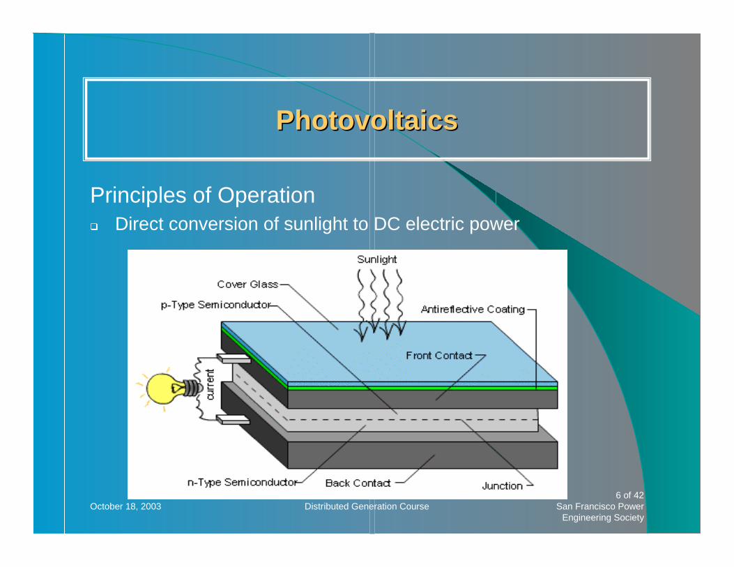
PhotovoltaicsPhotovoltaics
Principles of OperationDirect conversion of sunlight to DC electric power

October 18, 2003 Distributed Generation Course7 of 42
San Francisco Power Engineering Society
PhotovoltaicsPhotovoltaics(cont’d)(cont’d)
Efficiency100’s of watts to MW sizeDepends on efficiency, insolation, orientation and shading
Insolation varies throughout the day. Peak is about 1000 watts/square meter. Daily average is about 250 watts/ square meter.A fixed panel is cheaper than a tracking system but power output is reduced.A typical system will produce about 100 peak watts/square meter and about 200kwh/year per square meter.
Special RequirementsRequires an inverter to produce 60Hz AC power of sufficient voltage.
October 18, 2003 Distributed Generation Course8 of 42
San Francisco Power Engineering Society
PhotovoltaicsPhotovoltaics(cont’d)(cont’d)
AdvantagesNo emissionsNo moving partsLow maintenanceLong life Potential
DisadvantagesInitial CostLow utilization factorLow energy density, a large surface is requiredPV output will decrease if shaded by adjacent buildings or trees
October 18, 2003 Distributed Generation Course9 of 42
San Francisco Power Engineering Society
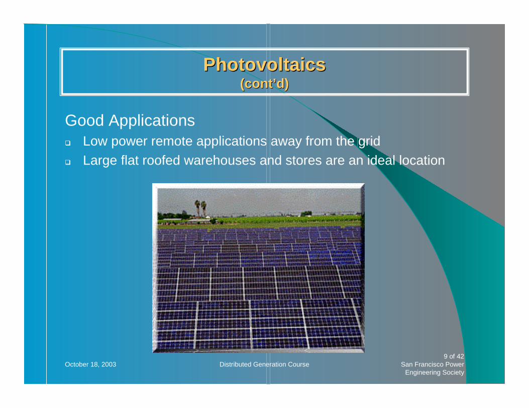
PhotovoltaicsPhotovoltaics(cont’d)(cont’d)
Good ApplicationsLow power remote applications away from the gridLarge flat roofed warehouses and stores are an ideal location

October 18, 2003 Distributed Generation Course10 of 42
San Francisco Power Engineering Society
Wind TurbineWind Turbine
October 18, 2003 Distributed Generation Course11 of 42
San Francisco Power Engineering Society
Wind TurbineWind Turbine(cont’d)(cont’d)
Principle of OperationConvert the kinetic energy of the wind to rotational motion of ageneratorUse of variable speed generators and inverters allows variable speed operation
Increases efficiencyReduces blade loads and weight
The most successful designs are horizontal axis with 3 blades.
EfficiencyApproximately 20 –40%

October 18, 2003 Distributed Generation Course12 of 42
San Francisco Power Engineering Society
Wind TurbineWind Turbine(cont’d)(cont’d)
Power Output100s of watts to 5MWPower is proportional to wind speed cubed and diameter squaredA 25ft diameter wind turbine produces about 10KW at 25mph wind speedTypical capacity factor approximately 25%
Special RequirementsNeed to be in areas of consistent high wind speeds
October 18, 2003 Distributed Generation Course13 of 42
San Francisco Power Engineering Society
Wind TurbineWind Turbine(cont’d)(cont’d)
AdvantagesRelatively low costNo emissions
DisadvantagesThe end user of electricity rarely is in a high wind area and there are restrictions on installation of towers.Weather dependent
Good ApplicationsLimited use by individuals in remote areasPrincipal use is in large wind farms
Not a typically distributed generator

October 18, 2003 Distributed Generation Course14 of 42
San Francisco Power Engineering Society
Small HydroSmall Hydro
Principle of OperationConverts the potential energy of falling water into rotation of a generator.Typically use Pelton wheels

October 18, 2003 Distributed Generation Course15 of 42
San Francisco Power Engineering Society
Small HydroSmall Hydro(cont’d)(cont’d)
EfficiencyAbout 80%
Power Output100’s of watts to MW’sA function of available head and water flow
Special RequirementsRequire penstocks and sometimes dams
AdvantagesLow cost
DisadvantagesLimited sitesPermitting is difficult
October 18, 2003 Distributed Generation Course16 of 42
San Francisco Power Engineering Society
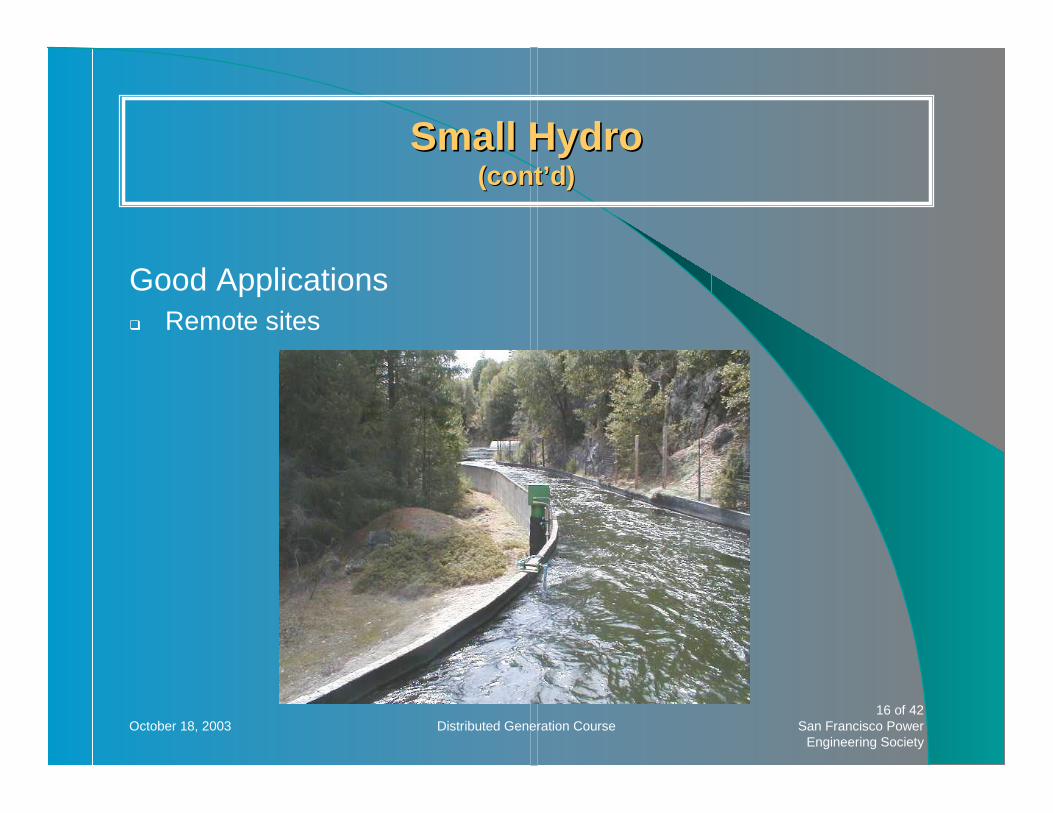
Small HydroSmall Hydro(cont’d)(cont’d)
Good ApplicationsRemote sites

October 18, 2003 Distributed Generation Course17 of 42
San Francisco Power Engineering Society
Conventional Gas TurbineConventional Gas Turbine
October 18, 2003 Distributed Generation Course18 of 42
San Francisco Power Engineering Society
Conventional Gas TurbineConventional Gas Turbine(cont’d)(cont’d)
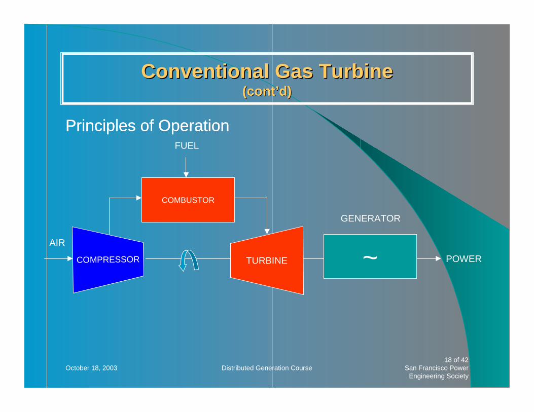
Principles of Operation
COMBUSTOR
COMPRESSOR TURBINE ~
GENERATOR
AIR
POWER
FUEL
Principles of Operation
October 18, 2003 Distributed Generation Course19 of 42
San Francisco Power Engineering Society
Conventional Gas TurbineConventional Gas Turbine(cont’d)(cont’d)
Efficiency20-40% (size dependent)Up to 80% when used for cogeneration
FuelsNatural gas, liquid fuels
Power Output500 KW – 100 MWDependent on ambient conditions

October 18, 2003 Distributed Generation Course20 of 42
San Francisco Power Engineering Society
Conventional Gas TurbineConventional Gas Turbine(cont’d)(cont’d)
Special RequirementsHigh pressure gas or gas compressor requiredTo meet California emissions limits
Use only natural gas andSteam injection orSelective catalytic reduction
In hot areas inlet air chillers or evaporative cooling helps maintain power output

October 18, 2003 Distributed Generation Course21 of 42
San Francisco Power Engineering Society
Conventional Gas TurbineConventional Gas Turbine(cont’d)(cont’d)
AdvantagesLow capital costProven technology
DisadvantagesAir permitting requiredRelatively skilled operating and maintenance personal required
Good ApplicationsMW size cogeneration at industrial facilities

October 18, 2003 Distributed Generation Course22 of 42
San Francisco Power Engineering Society
MicroturbineMicroturbine
Principles of OperationSimilar to conventional gas turbines but typically use single stage compressor and turbine.

October 18, 2003 Distributed Generation Course23 of 42
San Francisco Power Engineering Society
MicroturbineMicroturbine(cont’d)(cont’d)
Efficiency20-28%Up to 80% when used for cogeneration
Power Output25-500KW
FuelsNatural gas, liquid fuels, landfill gas (down to 350 BTU/scf)
Special RequirementsRequire 100psi gas or compressorCogeneration works best when providing hot water

October 18, 2003 Distributed Generation Course24 of 42
San Francisco Power Engineering Society
MicroturbineMicroturbine(cont’d)(cont’d)
AdvantagesPhysically small, packaged systems available with all controls and electrical protective functionsRelatively low capital costMeet California emissions requirementsIf used base loaded, yearly maintenance is limited to air filterreplacement
Disadvantages5 year lifeLife will be reduced by frequent starts and stops and cycling

October 18, 2003 Distributed Generation Course25 of 42
San Francisco Power Engineering Society
MicroturbineMicroturbine(cont’d)(cont’d)
Good ApplicationsCogeneration at commercial and industrial sitesLandfill power

October 18, 2003 Distributed Generation Course26 of 42
San Francisco Power Engineering Society
Internal Combustion EnginesInternal Combustion Engines
Principles of OperationUse either Otto cycle (similar to automotive engines) or diesel
Efficiency25-45%
FuelsNatural gas, diesel, landfill gas, digester gas
Power Output5KW - 7MW
October 18, 2003 Distributed Generation Course27 of 42
San Francisco Power Engineering Society
Internal Combustion EnginesInternal Combustion Engines(cont’d)(cont’d)
Special RequirementsTo meet California emissions requirements require SCR and use of natural gas
AdvantagesTechnically mature, widely used technology
DisadvantagesHigh noiseEmissionsMaintenance

October 18, 2003 Distributed Generation Course28 of 42
San Francisco Power Engineering Society
Internal Combustion EnginesInternal Combustion Engines((cont’d)cont’d)
Good ApplicationsCogeneration (using jacket water) at commercial and industrial sites

October 18, 2003 Distributed Generation Course29 of 42
San Francisco Power Engineering Society
Steam TurbineSteam Turbine
Principles of OperationExpand steam to produce rotation of a generator
EfficiencyApproximately 20-40% cycle efficiency
FuelsBoiler required
Can burn a variety of fuels
October 18, 2003 Distributed Generation Course30 of 42
San Francisco Power Engineering Society
Steam TurbineSteam Turbine(cont’d)(cont’d)
Power OutputKW – MW size
Special RequirementsRequires a boiler with sufficient pressure and temperature steamRequires overspeed protection
October 18, 2003 Distributed Generation Course31 of 42
San Francisco Power Engineering Society
Steam TurbineSteam Turbine(cont’d)(cont’d)
AdvantagesLow cost if boiler exists
DisadvantagesTypical commercial and industrial boilers do not provide high pressure steam
Good ApplicationsLimited uses for distributed generationMay be part of a combined cycle plant in which gas turbine waste heat is recovered in a heat exchanger to run a steam turbine.
October 18, 2003 Distributed Generation Course32 of 42
San Francisco Power Engineering Society
Fuel CellsFuel Cells
Principles of OperationFour types under development
Phosphoric Acid (PAFC)Molton Carbonate (MCFC)Solid Oxide (SOFC)Proton Exchange Membrane (PEMFC)
Similar to a battery (chemical reaction)
October 18, 2003 Distributed Generation Course33 of 42
San Francisco Power Engineering Society
Fuel CellsFuel Cells(cont’d)(cont’d)
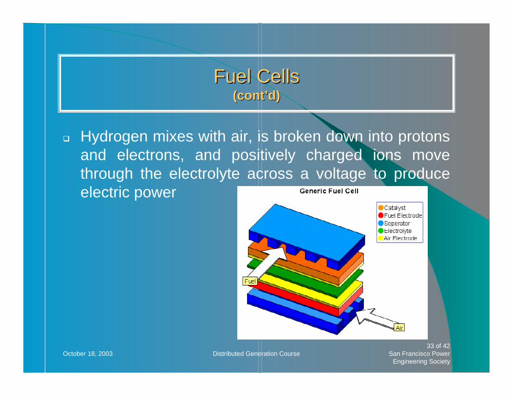
Hydrogen mixes with air, is broken down into protons and electrons, and positively charged ions move through the electrolyte across a voltage to produce electric power

October 18, 2003 Distributed Generation Course34 of 42
San Francisco Power Engineering Society
Efficiency30-60%
FuelsNatural gas, hydrogen. Some can use landfill gas, propane, and diesel
Power Output1 KW-10MW
Special RequirementsNon hydrogen fuels must be reformed into hydrogen (e.g., steam reformer for methane)
Fuel CellsFuel Cells(cont’d)(cont’d)

October 18, 2003 Distributed Generation Course35 of 42
San Francisco Power Engineering Society
Fuel CellsFuel Cells(cont’d)(cont’d)
AdvantagesHigh efficiencyPotentially 0 emissions
DisadvantagesComplexStill experimentalHigh cost
Good ApplicationsOnce perfected could have very wide application
October 18, 2003 Distributed Generation Course36 of 42
San Francisco Power Engineering Society
Fuel CellsFuel Cells(cont’d)(cont’d)

October 18, 2003 Distributed Generation Course37 of 42
San Francisco Power Engineering Society
Hybrid Fuel Cell/MicroturbineHybrid Fuel Cell/Microturbine
Principles of Operation
COMBUSTOR
COMPRESSOR TURBINE ~
GENERATOR
POWER
FUEL CELL
POWER
FUEL FUEL
AIR
O Fuel cell efficiency is improved at high pressure
O Combines a solidoxide fuel cell with a microturbine

October 18, 2003 Distributed Generation Course38 of 42
San Francisco Power Engineering Society
Hybrid Fuel Cell/MicroturbineHybrid Fuel Cell/Microturbine(cont’d)(cont’d)
Efficiency60-70%
FuelsNatural gas, hydrogen
October 18, 2003 Distributed Generation Course39 of 42
San Francisco Power Engineering Society
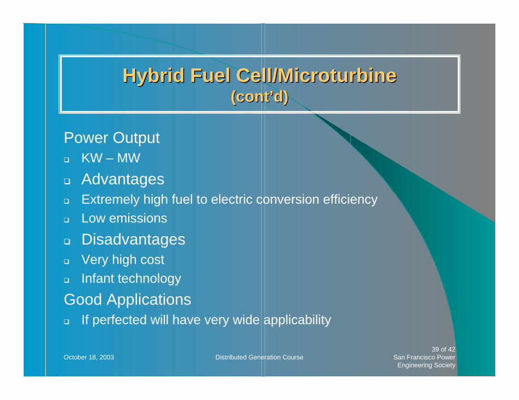
Hybrid Fuel Cell/MicroturbineHybrid Fuel Cell/Microturbine(cont’d)(cont’d)
Power OutputKW – MW
AdvantagesExtremely high fuel to electric conversion efficiencyLow emissions
DisadvantagesVery high costInfant technology
Good ApplicationsIf perfected will have very wide applicability

October 18, 2003 Distributed Generation Course40 of 42
San Francisco Power Engineering Society
Installed CostsInstalled Costs

October 18, 2003 Distributed Generation Course41 of 42
San Francisco Power Engineering Society
CONCLUSIONSCONCLUSIONS
October 18, 2003 Distributed Generation Course42 of 42
San Francisco Power Engineering Society
Many technologies are available and proven
Distributed generation has barely made inroads in a potentially massive market
Distributed generation has huge potential to reduce fossil fuel consumption via the high efficiency of cogeneration v.s. centralized power plants
For more information, see: www.energy.ca.gov/distgen
Distributed Generation Principles Electrical Systems
Presented by Dr. ShyShenq Liou San Francisco State University
IEEE San Francisco Power Engineering Society
DG Fundamentals WorkshopSan Francisco State University
October 18, 2003

Solar Power
•Fundamentals•Electrical Characteristics•Cell, Module, and Array•Maximum Power Tracker•Power Electronics Circuits

October 18, 2003Distributed Generation Course
San Francisco Power Engineering Society 3 of 38
p-type mateiral
n-type material
EHP
Electron
Hole
IncomingPhoton
Basic Operation of Solar pn Junction
October 18, 2003Distributed Generation Course
San Francisco Power Engineering Society 4 of 38
−−= 1kT
qV
ol eIII
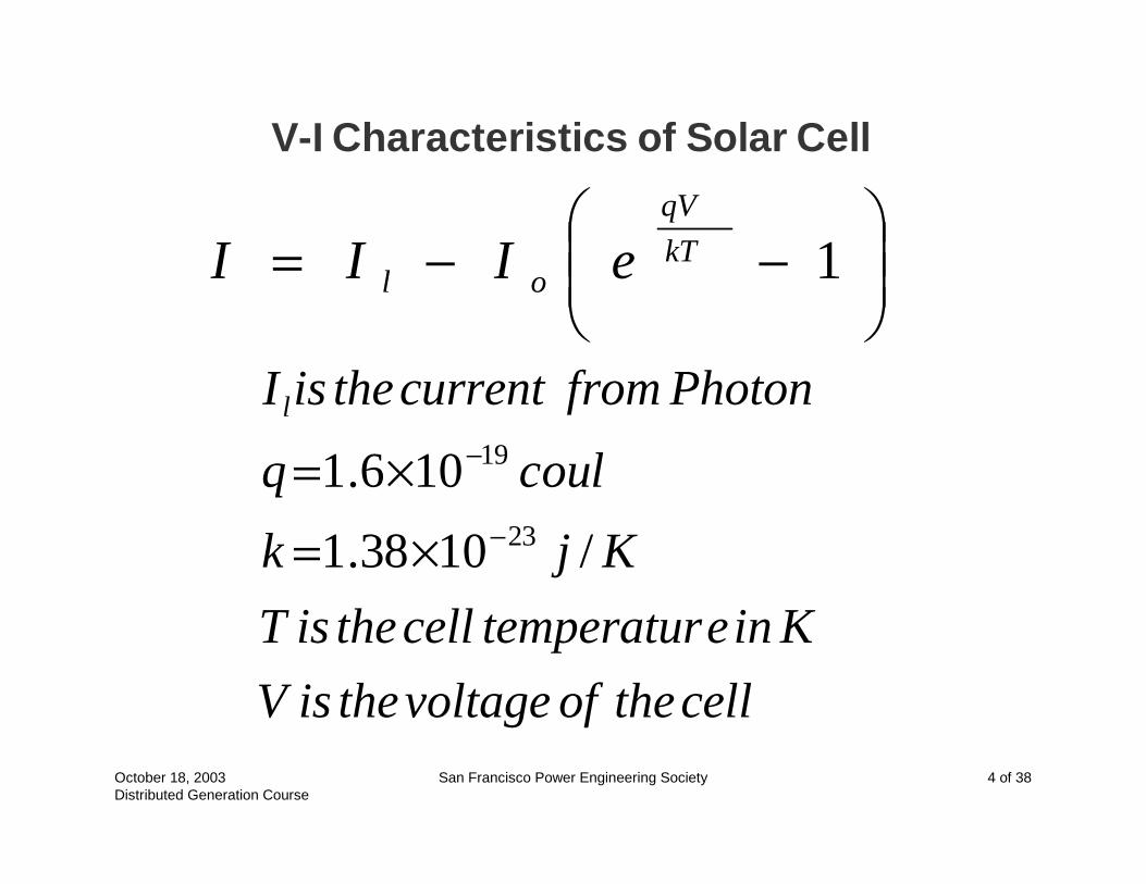
V-I Characteristics of Solar Cell
celltheofvoltagetheisV
KinetemperaturcelltheisT
Kjk
coulq
PhotonfromcurrenttheisIl
/1038.1
106.123
19
−
−
×=×=

October 18, 2003Distributed Generation Course
San Francisco Power Engineering Society 5 of 38
OCSCmm
o
olOC
lSC
VIFFVIP
I
II
q
kTV
II
==
+=
=
max
ln
FF is the cell fill factor

October 18, 2003Distributed Generation Course
San Francisco Power Engineering Society 6 of 38
Cell Voltage
Cel
l Cur
rent
I-V Characteristics of Solar Cell
Illumination Level

October 18, 2003Distributed Generation Course
San Francisco Power Engineering Society 7 of 38
V
ICell
Module
Array

October 18, 2003Distributed Generation Course
San Francisco Power Engineering Society 8 of 38
Blocking Diode
Bypass Diode

October 18, 2003Distributed Generation Course
San Francisco Power Engineering Society 9 of 38
Cell Voltage
Cel
l Cur
rent
Illumination Level
Load Line
Load Line
Load Line
Concept of Maximum Power Tracker

October 18, 2003Distributed Generation Course
San Francisco Power Engineering Society 10 of 38
MOSFET
CellModule
Indu
ctor
Diode
Cap
acito
r
Res
isto
r
Buck-Boost DC to DC Converter
inout VD
DV
−=
1

Overview of Fuel Cell
•Brief Introduction•Fundamentals•Electrical Characteristics
Brief Introduction
• Fuel Cell was invented by William R. Grove in 1839. It was called “Gaseous Voltaic Battery
• Fuel Cell is an electrochemical “device” that continuously converts chemical energy into electric energy (and some heat) for as long as fuel and oxidant are supplied.
Three Major Applications
• Transportation–Automobiles
• Stationary Power Generation–Low CO2 emission–CHP
• Portable Applications–Camping–Yachting
October 18, 2003Distributed Generation Course
San Francisco Power Engineering Society 14 of 38
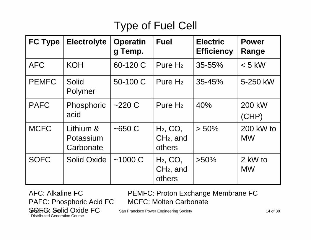
Type of Fuel Cell
2 kW to MW
>50%H2, CO, CH2, and others
~1000 CSolid OxideSOFC
200 kW to MW
> 50%H2, CO, CH2, and others
~650 CLithium & Potassium Carbonate
MCFC
200 kW(CHP)
40%Pure H2~220 CPhosphoric acid
PAFC
5-250 kW35-45%Pure H250-100 CSolid Polymer
PEMFC
< 5 kW35-55%Pure H260-120 CKOHAFC
Power Range
Electric Efficiency
FuelOperating Temp.
ElectrolyteFC Type
AFC: Alkaline FC PEMFC: Proton Exchange Membrane FCPAFC: Phosphoric Acid FC MCFC: Molten CarbonateSOFC: Solid Oxide FC

October 18, 2003Distributed Generation Course
San Francisco Power Engineering Society 15 of 38
Membrane Electrode Assembly of PEMFC
inH 2 inO2
−e
Ano
de
Cat
hode
+H+H
+H
+H
+H
M embrane
Catalyst LayerGas D iffusion
Layer/Substrate
)23.1(222
1
22
22
2
VEOHeHO
eHH
r =→++
+→
−+
−+outOH 2

October 18, 2003Distributed Generation Course
San Francisco Power Engineering Society 16 of 38
V-I Characteristic of Fuel CellC
ell P
oten
tial i
n vo
lt
C ell C urrent in A/(cm square)
Power C urve
Effic iency of FC ~ to C ell Voltage
October 18, 2003Distributed Generation Course
San Francisco Power Engineering Society 17 of 38
Wind Power
• Major components• Typical Wind Turbine Power Curve• Possible choices of generator• Power Electronics
October 18, 2003Distributed Generation Course
San Francisco Power Engineering Society 18 of 38
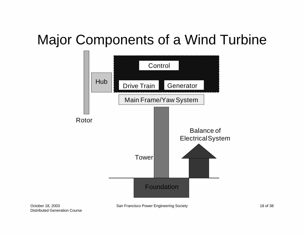
Major Components of a Wind Turbine
Rotor
Hub
Control
Drive Train Generator
Main Frame/Yaw System
Tower
Foundation
Balance ofElectrical System
October 18, 2003Distributed Generation Course
San Francisco Power Engineering Society 19 of 38
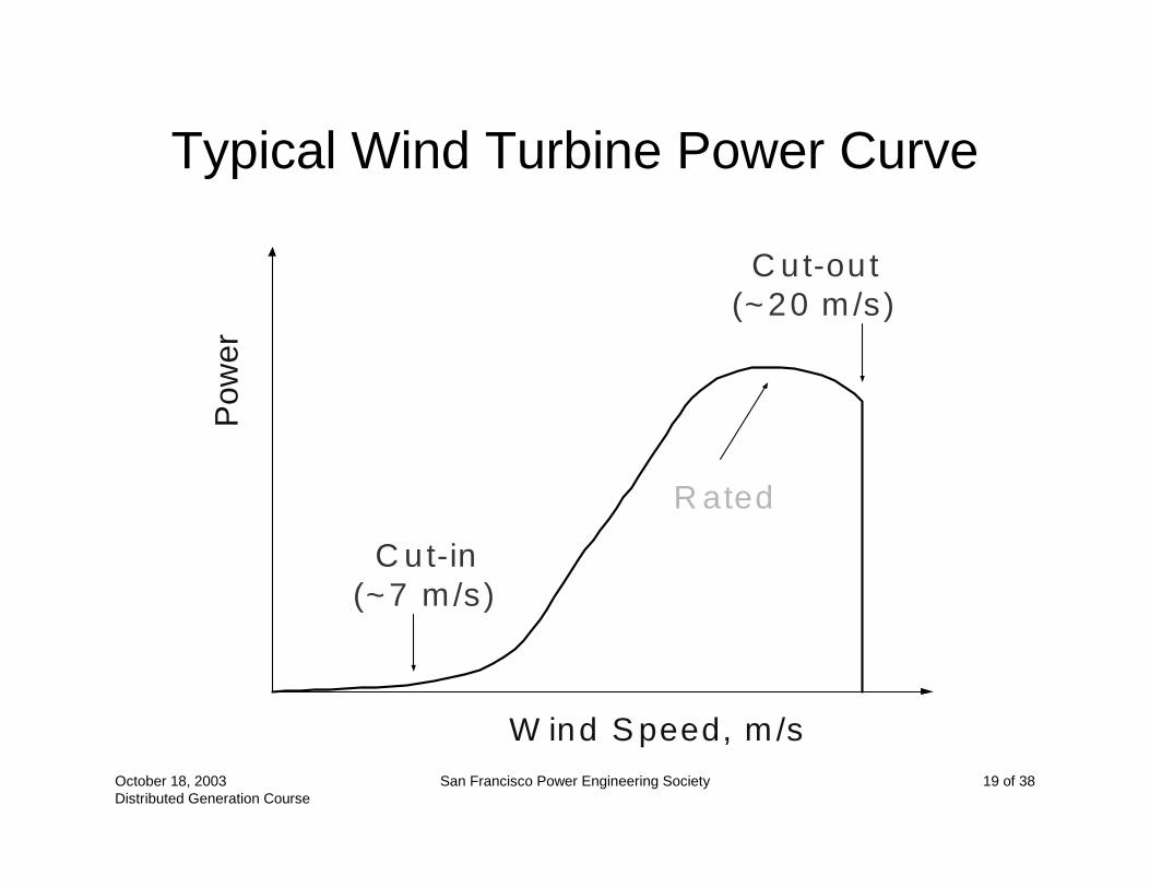
Typical Wind Turbine Power Curve
W ind S peed, m /s
Pow
er
C u t-in(~7 m/s)
R ated
C ut-ou t(~20 m /s)
October 18, 2003Distributed Generation Course
San Francisco Power Engineering Society 20 of 38
Possible Generators
• Synchronous Machine• Induction Machine• Permanent Magnet Synchronous Machine• Direct Drive Generator• Switched Reluctance Generator• DC Machine
– DC Shunt Machine
– High Maintenance and high cost
October 18, 2003Distributed Generation Course
San Francisco Power Engineering Society 21 of 38
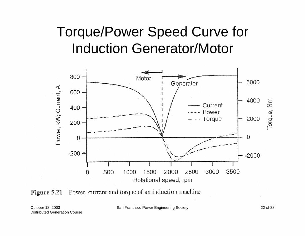
Induction Machine
• Motoring when speed is less than synchronous speed– 2-pole: 3600 RPM– 4-pole:1800 RPM– 6-pole: 1200 RPM
• Generating when speed is above the synchronous
• Slip is usually 2% to 3%• Self starting using wind!• Run as induction motor to start!
October 18, 2003Distributed Generation Course
San Francisco Power Engineering Society 22 of 38
Torque/Power Speed Curve for Induction Generator/Motor
October 18, 2003Distributed Generation Course
San Francisco Power Engineering Society 23 of 38
Synchronous Machine
• Usually started by the wind• Synchronization is needed to connect to
existing AC power system• Active rotor speed control maybe needed

October 18, 2003Distributed Generation Course
San Francisco Power Engineering Society 24 of 38
Permanent Magnet Machine
• Generator of choice for <10 kW unit• Permanent magnets mounted on rotor
provides field excitation• Armature on stator is stationary! No need
to have commutator, slip rings, brushes!• AC output has variable frequency and
magnitude. • Rectified to DC, inverted to AC, then
connected to grid.
October 18, 2003Distributed Generation Course
San Francisco Power Engineering Society 25 of 38
Direct Drive Generator
• Synchronous Generator of special design• Large no. of poles so it can be coupled to
the wind turbine rotor. No gearbox is needed.
• Diameter is large!• Power Converters are needed to cope with
varying magnitude and frequency!
October 18, 2003Distributed Generation Course
San Francisco Power Engineering Society 26 of 38
Switched Reluctance Machine
• a.k.a. Variable Reluctance Machine• A huge stepper motor or generator• Popular in traction applications• Electrical characteristics are similar to
those of series DC machines• Made possible because of power
electronics and digital control• Difficult to compete against Induction
Machines economically

October 18, 2003Distributed Generation Course
San Francisco Power Engineering Society 27 of 38
Power Converter
• Block diagram of a motor drive where the power flow is unidirectional
October 18, 2003Distributed Generation Course
San Francisco Power Engineering Society 28 of 38
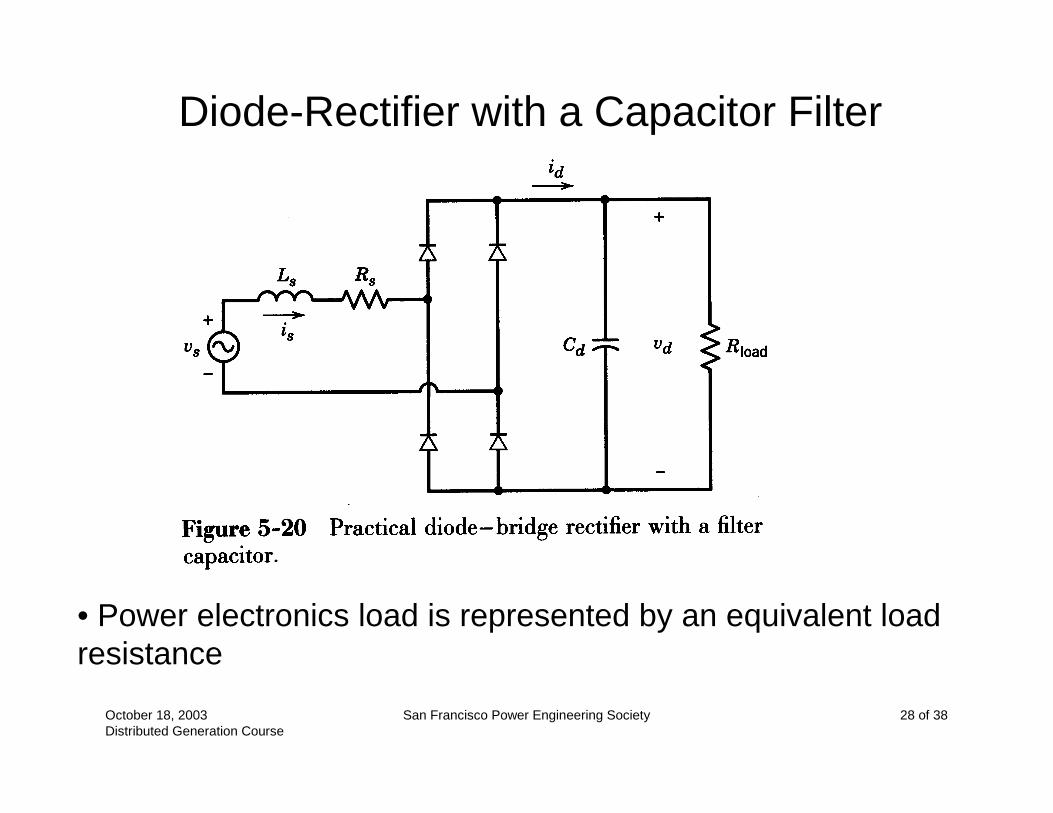
Diode-Rectifier with a Capacitor Filter
• Power electronics load is represented by an equivalent load resistance

October 18, 2003Distributed Generation Course
San Francisco Power Engineering Society 29 of 38
Three-Phase, Full-Bridge Rectifier
• Commonly used
October 18, 2003Distributed Generation Course
San Francisco Power Engineering Society 30 of 38
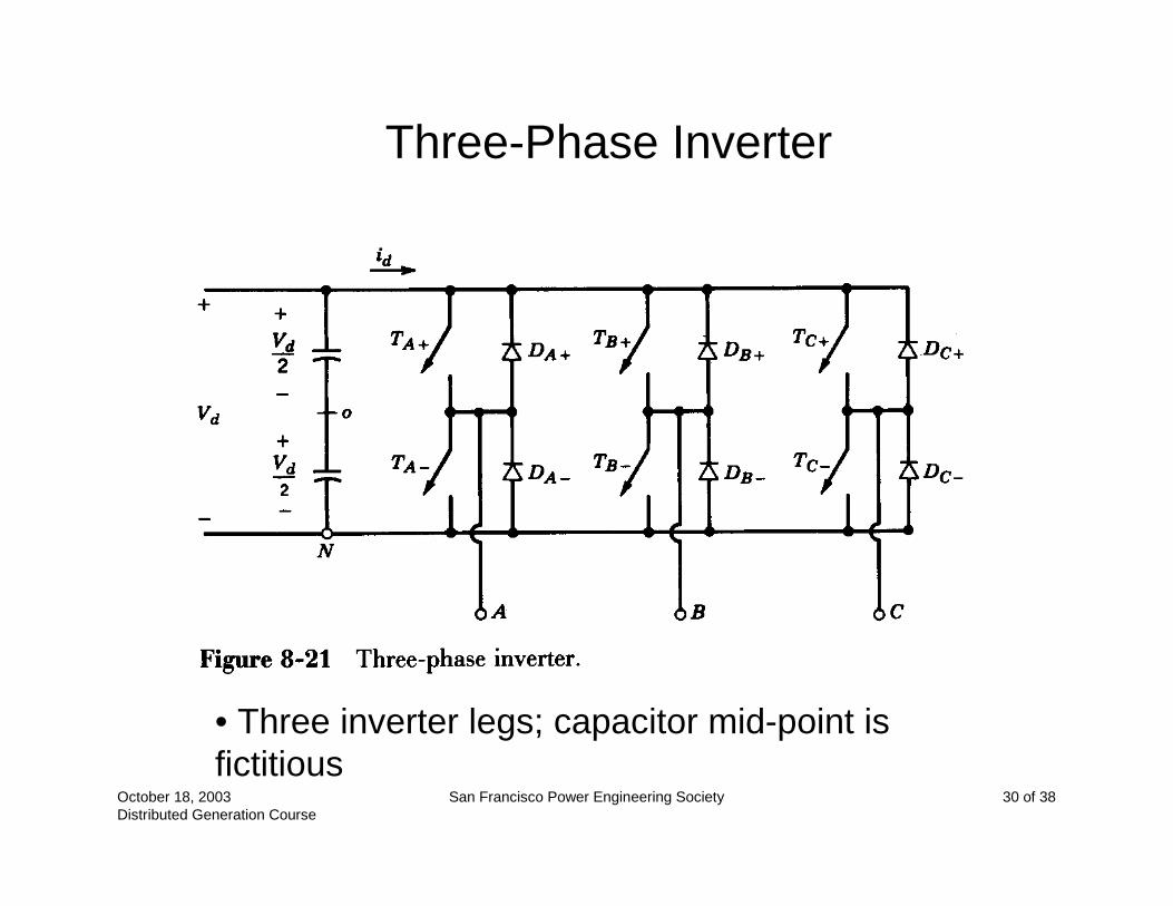
Three-Phase Inverter
• Three inverter legs; capacitor mid-point is fictitious

October 18, 2003Distributed Generation Course
San Francisco Power Engineering Society 31 of 38
Switch-Mode DC-AC Inverter
• Block diagram of a motor drive where the power flow can be bi-directional

October 18, 2003Distributed Generation Course
San Francisco Power Engineering Society 32 of 38
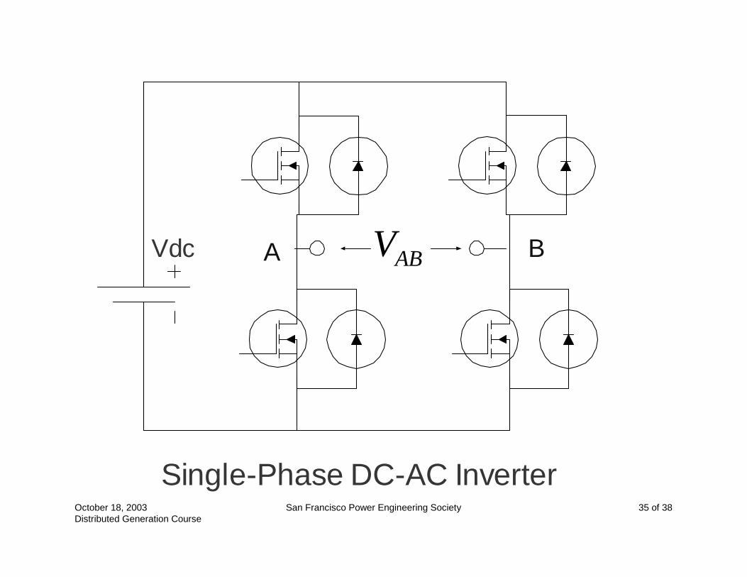
Vdc A B
Single-Phase DC-AC Inverter
ABV
October 18, 2003Distributed Generation Course
San Francisco Power Engineering Society 33 of 38
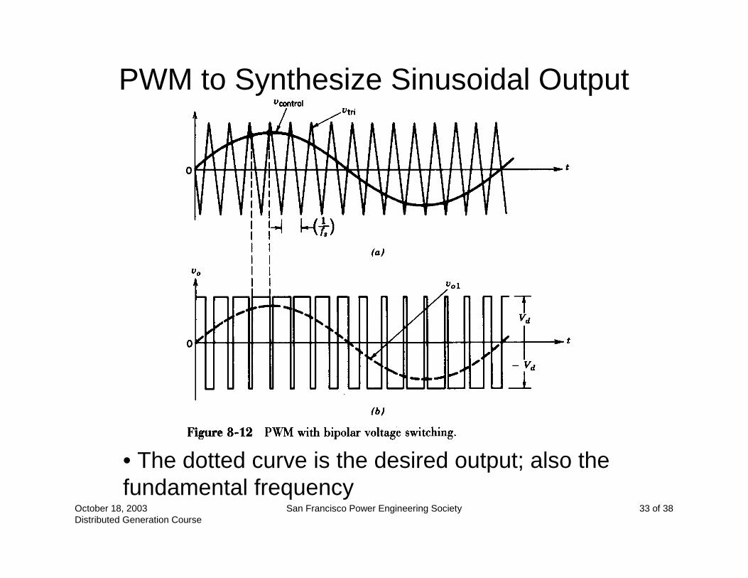
PWM to Synthesize Sinusoidal Output
• The dotted curve is the desired output; also the fundamental frequency

October 18, 2003Distributed Generation Course
San Francisco Power Engineering Society 34 of 38
Three-Phase PWM
Waveforms
October 18, 2003Distributed Generation Course
San Francisco Power Engineering Society 35 of 38
Vdc A B
Single-Phase DC-AC Inverter
ABV

October 18, 2003Distributed Generation Course
San Francisco Power Engineering Society 36 of 38
AC AC
SourceV
ABV
Current I
IjIX
ABV
SourceV
X
pf = 0, leading
October 18, 2003Distributed Generation Course
San Francisco Power Engineering Society 37 of 38
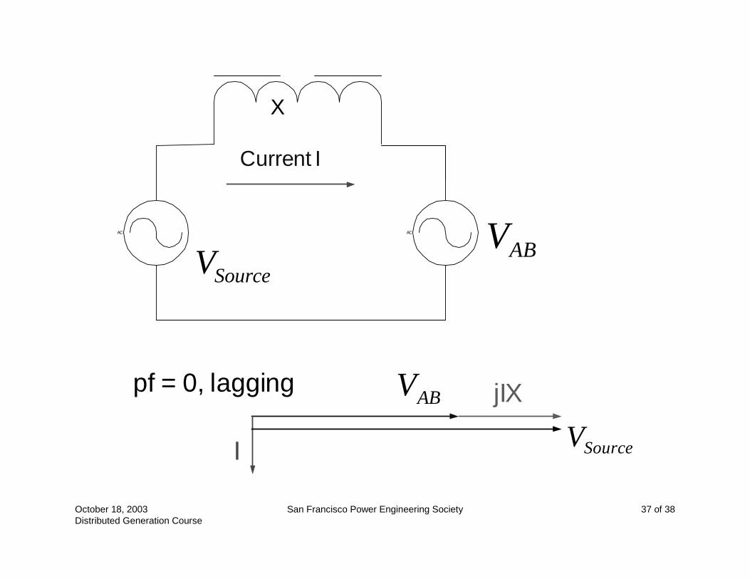
AC AC
SourceV
ABV
Current I
I
jIX
ABV
SourceV
X
pf = 0, lagging
October 18, 2003Distributed Generation Course
San Francisco Power Engineering Society 38 of 38
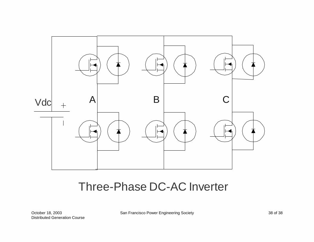
Vdc A B
Three-Phase DC-AC Inverter
C
Distribution System CharacteristicsDistribution System Characteristics
Presented by Willie Chew Pacific Gas & Electric Company
IEEE San Francisco Power Engineering Society
DG Fundamentals Workshop
San Francisco State University
October 18, 2003
October 18, 2003 Distributed Generation CourseSan Francisco Power Engineering Society 2 of 21
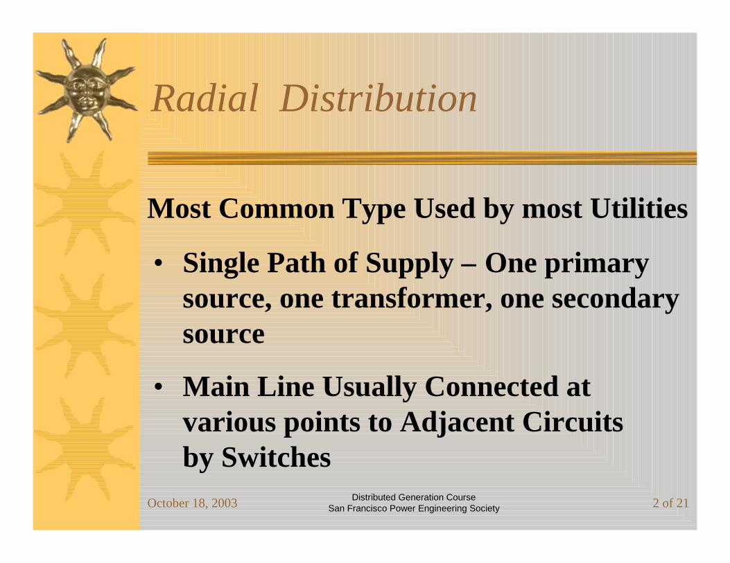
Most Common Type Used by most Utilities
• Single Path of Supply – One primary source, one transformer, one secondary source
• Main Line Usually Connected at various points to Adjacent Circuits by Switches
Radial Distribution
October 18, 2003 Distributed Generation CourseSan Francisco Power Engineering Society 3 of 21
Mainly used for overhead distribution systems
• Customers exposed to outages when equipment fails
• Easy to locate trouble and faults
• Cost effective to install
Radial Primary Feeder
October 18, 2003 Distributed Generation CourseSan Francisco Power Engineering Society 4 of 21
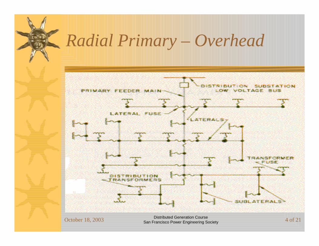
Radial Primary – Overhead
October 18, 2003 Distributed Generation CourseSan Francisco Power Engineering Society 5 of 21
• Fuses
• Line Reclosers
• Circuit breaker at substation has automatic reclosing
-- Typical 3 shots to lockout
Overhead Line Protection

October 18, 2003 Distributed Generation CourseSan Francisco Power Engineering Society 6 of 21
• Mainly for Underground Distribution Systems
• Provides 2 Supply Paths for Loads
• Usually installed where there is a concentration of Commercial or Industrial Customers
Radial Loop Primary
October 18, 2003 Distributed Generation CourseSan Francisco Power Engineering Society 7 of 21
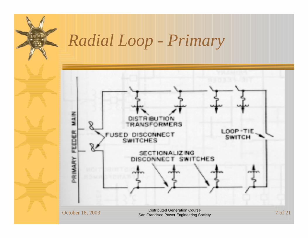
Radial Loop - Primary
October 18, 2003 Distributed Generation CourseSan Francisco Power Engineering Society 8 of 21
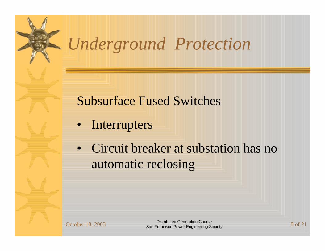
Subsurface Fused Switches
• Interrupters
• Circuit breaker at substation has no automatic reclosing
Underground Protection
October 18, 2003 Distributed Generation CourseSan Francisco Power Engineering Society 9 of 21
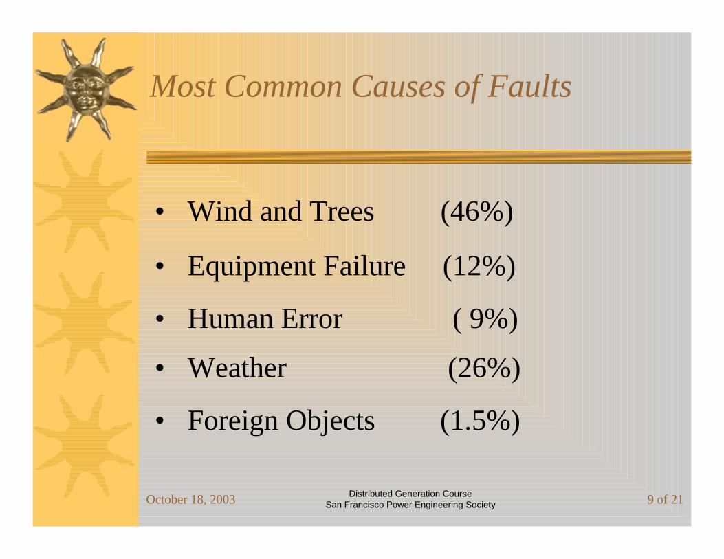
• Wind and Trees (46%)
• Equipment Failure (12%)
• Human Error ( 9%)
• Weather (26%)
• Foreign Objects (1.5%)
Most Common Causes of Faults

October 18, 2003 Distributed Generation CourseSan Francisco Power Engineering Society 10 of 21
• Load Tap Changers (LTC) on substation banks
• Station Capacitor Banks
• Field Capacitor Banks
• Autoboosters
Voltage Regulation
October 18, 2003 Distributed Generation CourseSan Francisco Power Engineering Society 11 of 21
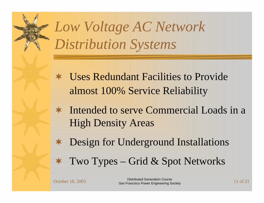
Low Voltage AC Network Distribution Systems
Uses Redundant Facilities to Provide almost 100% Service Reliability
Intended to serve Commercial Loads in a High Density Areas
Design for Underground Installations
Two Types – Grid & Spot Networks

October 18, 2003 Distributed Generation CourseSan Francisco Power Engineering Society 12 of 21
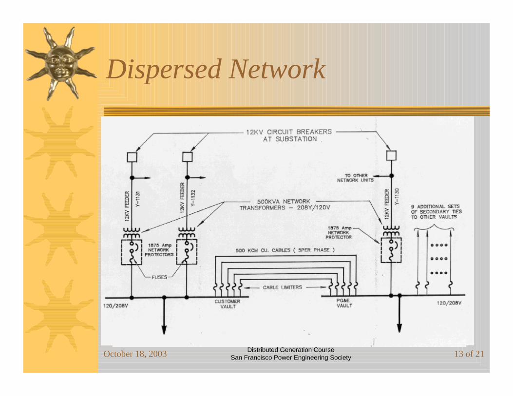
Grid or Dispersed Network
Used for Small to Medium Commercial Loads
Transformers dispersed over a Large Area
Has a “Grid” of Interconnected Cables energized at 120/208 Volt, 3 phase
Grid energized at multiple points by Transformers
Multiple Primary Circuits operate in parallel to supply power to Grid Transformers
October 18, 2003 Distributed Generation CourseSan Francisco Power Engineering Society 13 of 21
Dispersed Network

October 18, 2003 Distributed Generation CourseSan Francisco Power Engineering Society 14 of 21
Spot Networks
For Large Concentrated, Commercial Loads
Has Same Reliability and Operating Features as a Grid
Secondary Voltage is usually 277/480 Volt
Usually Serves only one Customer
Types of Customers: High Rise Office Bldgs and Hotels, Computer Facilities, Communication Centers, & Retail Centers
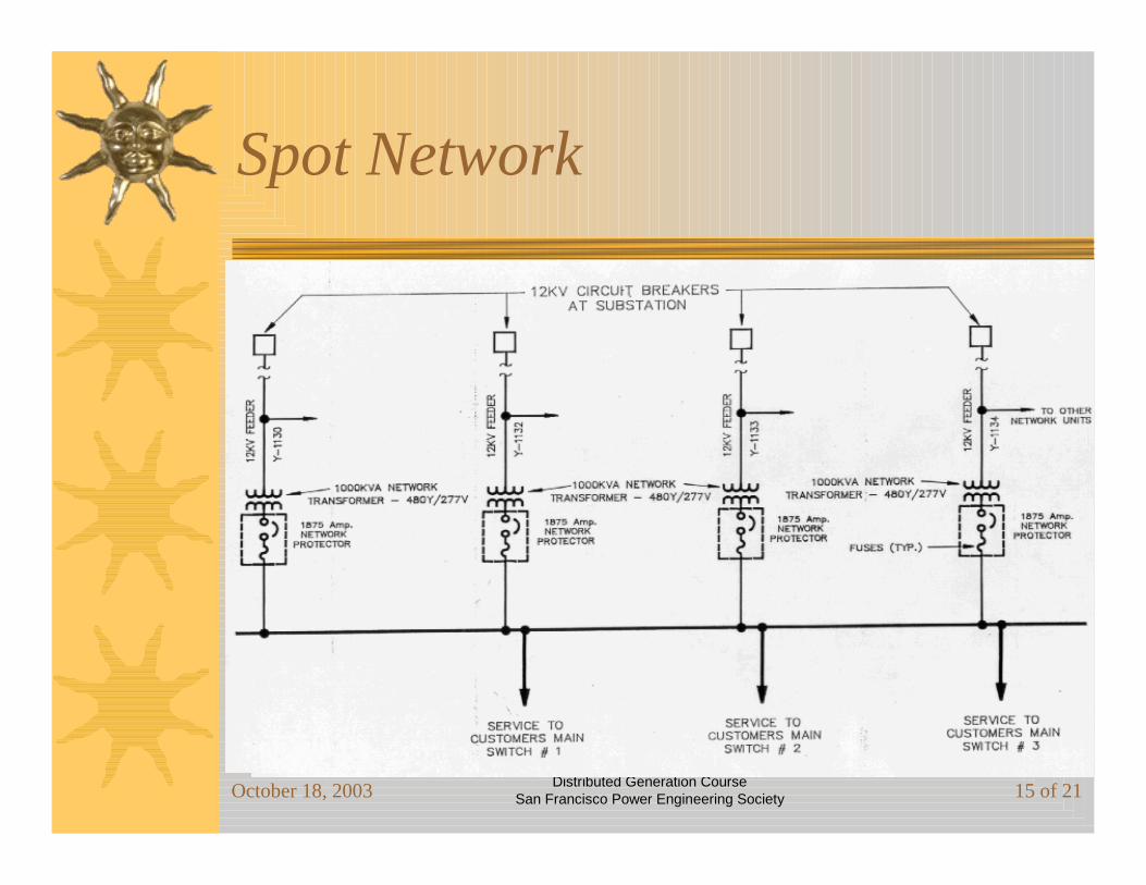
October 18, 2003 Distributed Generation CourseSan Francisco Power Engineering Society 15 of 21
Spot Network

October 18, 2003 Distributed Generation CourseSan Francisco Power Engineering Society 16 of 21
Disadvantages
High Secondary Fault Currents – Up to 200,000 Amp. In Certain Areas
Large Space Requirement for Transformer Vaults
Cost of Purchasing Multiple Transformers and Extension of Multiple Primary Circuits
Reliability affected by Bulk Power Source
October 18, 2003 Distributed Generation CourseSan Francisco Power Engineering Society 17 of 21
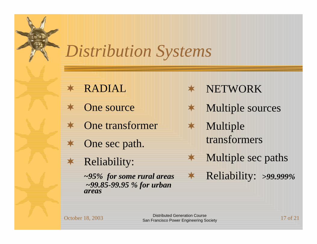
Distribution Systems
RADIAL
One source
One transformer
One sec path.
Reliability: ~95% for some rural areas~99.85-99.95 % for urban areas
NETWORK
Multiple sources
Multiple transformers
Multiple sec paths
Reliability: >99.999%

October 18, 2003 Distributed Generation CourseSan Francisco Power Engineering Society 18 of 21
Measured Reliability of Distribution Systems
Type of System RadialOverhead
Loop Radial System
Underground Loop Radial
System
Automatic Transfer Scheme
Grid Network
Spot Network
Outages Per Year 0.3 - 1.3 0.4 - 0.7 0.4 - 0.7 0.1 - 0.5 0.005 - 0.020 0.02 - 0.10
Average Outage Duration (min)
90 65 60 180 135 180
Momentary Interruptions Per Year
5 - 10 10 - 15 4 - 8 4 - 8 ~ 0 0 - 1
Table extracted from ELECTRICAL WORLD, May 1992
Based on information supplied by Consolidated Edison

October 18, 2003 Distributed Generation CourseSan Francisco Power Engineering Society 19 of 21
Fault Capabilities(3 phase RMS symmetrical)
36,000 to 175,000 Amp
18,000 to 52,000 Amp
Secondary(460 & 480 V)
3,000 to 200,000 Amp
10,000 to 42,000 Amp
Secondary (208 & 240 V)
8600 to 21,000 A. 13,500 t0 12,000 A.
600 to 21,000 Amp.
Primary (4 to 34.5 KV)
NetworkRadial Voltage
Assymmetry Factor : 1.0 to 1.6

October 18, 2003 Distributed Generation CourseSan Francisco Power Engineering Society 20 of 21
Commercial Load Pattern

October 18, 2003 Distributed Generation CourseSan Francisco Power Engineering Society 21 of 21
Residential Load Pattern

DG Fundamentals WorkshopOctober 2003
San Francisco Power Engineering SocietyDG Systems and Applications
1 of 55
Commercially AvailableDG Systems & Applications –
Gary Olson Cummins Power Generation
October 18, 2003
DG Fundamentals WorkshopOctober 2003
San Francisco Power Engineering SocietyDG Systems and Applications
2 of 55
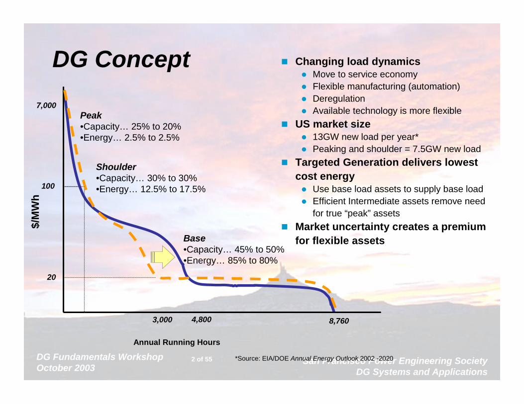
DG Concept Changing load dynamicsMove to service economyFlexible manufacturing (automation)DeregulationAvailable technology is more flexible
US market size13GW new load per year*Peaking and shoulder = 7.5GW new load
Targeted Generation delivers lowest cost energy
Use base load assets to supply base loadEfficient Intermediate assets remove need for true “peak” assets
Market uncertainty creates a premium for flexible assets
100
7,000Peak•Capacity… 25% to 20%•Energy… 2.5% to 2.5%
Shoulder•Capacity… 30% to 30%•Energy… 12.5% to 17.5%
Base•Capacity… 45% to 50% •Energy… 85% to 80%
$/M
Wh
Annual Running Hours
*Source: EIA/DOE Annual Energy Outlook 2002 -2020
8,7604,8003,000
20

DG Fundamentals WorkshopOctober 2003
San Francisco Power Engineering SocietyDG Systems and Applications
3 of 55
Drivers for New Technology
–Lower total cost• Equipment• Fuel efficiency
–Lower emissions–Power quality

DG Fundamentals WorkshopOctober 2003
San Francisco Power Engineering SocietyDG Systems and Applications
4 of 55
Technologies Reviewed• Recip Diesel Engines
• Advanced Recip Gaseous Fuel Engines
• Gas Turbines• Microturbines• Fuel cells
• Wind/Solar

DG Fundamentals WorkshopOctober 2003
San Francisco Power Engineering SocietyDG Systems and Applications
5 of 55
Diesel RecipLow $/kWHigh efficiencyNOx/PM Issues
Natural Gas RecipLow emissionsLow $/kWCogen optionsSize IssuesFuel issues
Fuel CellUltra low emissionsHigh efficiencyCogen optionsVery high $/kWSize Issues
MicroturbineFuel tolerantVery low emissionsCompact sizeCogen optionsHigh $/kW
Application needsHours operation?
Capital availability?
Permitting requirements?
Fuel availability?
How do the Technologies andMarkets Fit Together?
DG Fundamentals WorkshopOctober 2003
San Francisco Power Engineering SocietyDG Systems and Applications
6 of 55
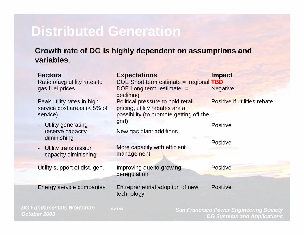
Distributed GenerationGrowth rate of DG is highly dependent on assumptions and variables.
FactorsRatio of avg utility rates togas fuel prices
ExpectationsDOE Short term estimate = regionalDOE Long term estimate. =declining
ImpactTBDNegative
Peak utility rates in highservice cost areas (< 5% ofservice)
- Utility generatingreserve capacitydiminishing
- Utility transmissioncapacity diminishing
Political pressure to hold retailpricing, utility rebates are apossibility (to promote getting off thegrid)
New gas plant additions
More capacity with efficientmanagement
Positive if utilities rebate
Positive
Positive
Utility support of dist. gen. Improving due to growingderegulation
Positive
Energy service companies Entrepreneurial adoption of newtechnology
Positive
DG Fundamentals WorkshopOctober 2003
San Francisco Power Engineering SocietyDG Systems and Applications
7 of 55
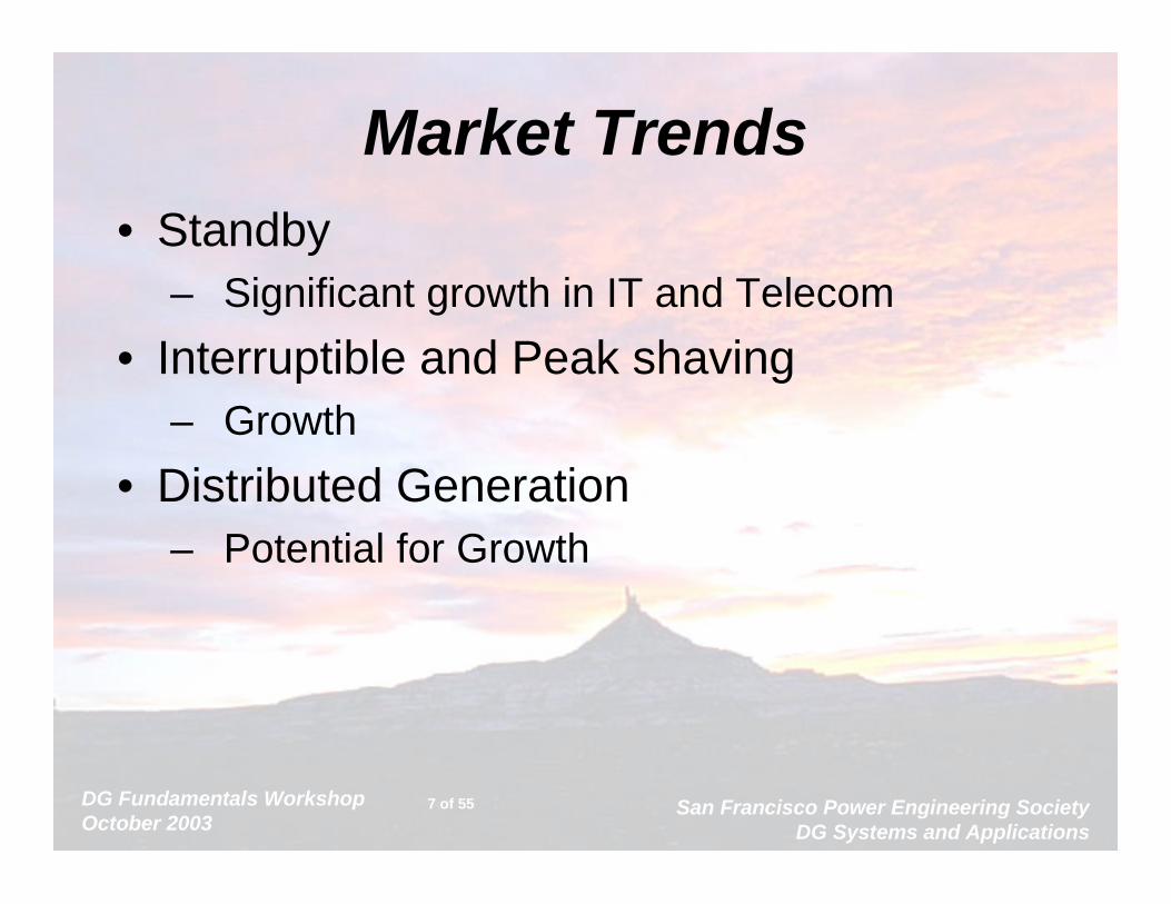
Market Trends• Standby
– Significant growth in IT and Telecom
• Interruptible and Peak shaving– Growth
• Distributed Generation– Potential for Growth
DG Fundamentals WorkshopOctober 2003
San Francisco Power Engineering SocietyDG Systems and Applications
8 of 55
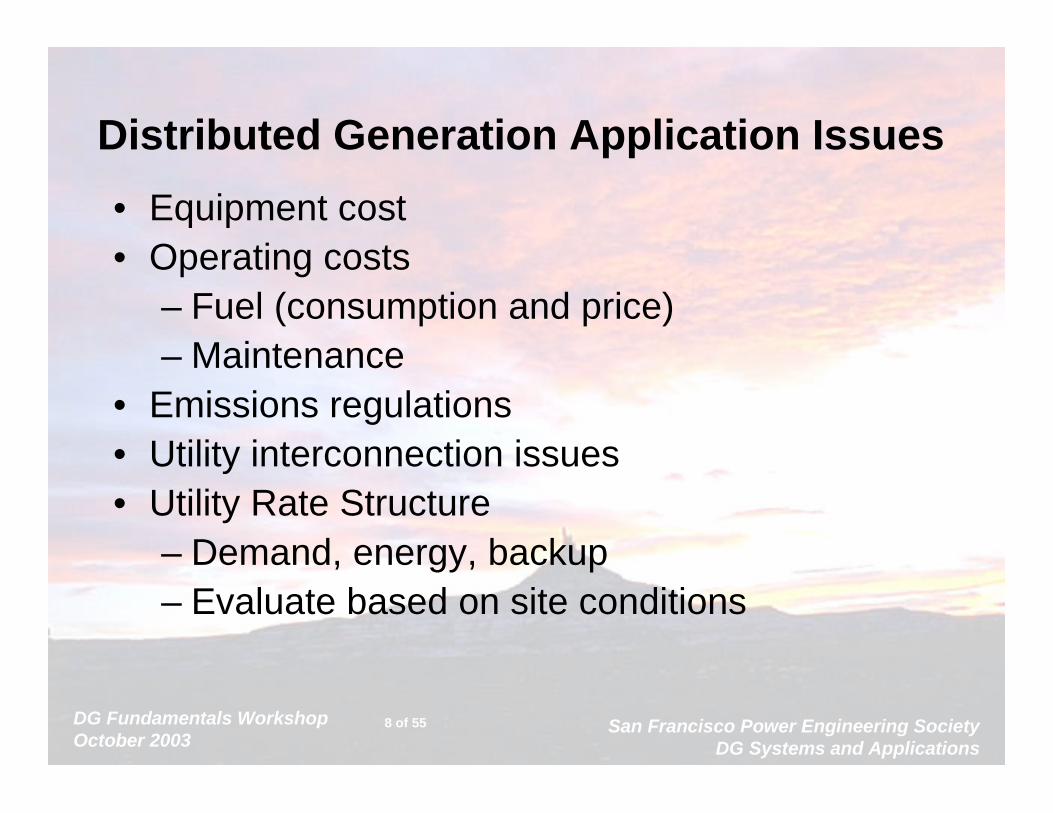
• Equipment cost• Operating costs
– Fuel (consumption and price)– Maintenance
• Emissions regulations• Utility interconnection issues• Utility Rate Structure
– Demand, energy, backup– Evaluate based on site conditions
Distributed Generation Application Issues

DG Fundamentals WorkshopOctober 2003
San Francisco Power Engineering SocietyDG Systems and Applications
9 of 55
Pros and Cons for DG• Pro:
– Low risk venture– Returns can be very good– Improves Facility Power
System Reliability• “Free” Standby
– Test/Exercise Benefits
• Con:– Most Customers are not in the
power generation business– Return may not be as high as
other projects competing for capital
– More complex power system• less reliable?
– Environmental Issues• Exhaust• Noise

DG Fundamentals WorkshopOctober 2003
San Francisco Power Engineering SocietyDG Systems and Applications
10 of 55
Equipment Costs Vs Technology
0
500
1000
1500
2000
2500
3000
1 10 100 1000 10000 100000
Power (Kw)
Pric
e ($
/kW
e)
Fuel Cells Near Term
Natural Gas Recip
Gas Turbine(Non-recuperated)
Diesel Recip
Microturbine(Recuperated)
DOE Fuel Cell Program Targets Long Term
FY03 TQG
Be t
ter

DG Fundamentals WorkshopOctober 2003
San Francisco Power Engineering SocietyDG Systems and Applications
11 of 55
Thermal Efficiency Vs. Technology
0.10
0.15
0.20
0.25
0.30
0.35
0.40
0.45
0.50
0.55
1 10 100 1000 10000
Power (kWe)
Ele
ctri
cal E
ffic
ienc
y (f
ull l
oad)
Gas Turbine(Non-recuperated)
Gas TurbineRecuperated
Fuel Cells Diesel Recip
Natural Gas Recip(Stoichiometric)
Natural Gas Recip(Lean Burn)
Fuel Cell/ Microturbine Target 60-70%
DOE Fuel Cell Target
Bet
ter
Hydrocarbon Fuels
Stationary
Mobile

DG Fundamentals WorkshopOctober 2003
San Francisco Power Engineering SocietyDG Systems and Applications
12 of 55
CHP = Cogeneration
Mechanical
Thermal
Electrical output 42%
HT circuit (90-100°C)16%
Lube Oil circuit (75-90°C) 5%
Exhaust gas (120° + unburnt HC.) 8%
Generator losses 1%
Cooling circuit CAC 2%
Exhaust gas ( -> 120°C) 24%
Engine radiation 3%
Total efficiency
87 %
Losses 14 %
DG Fundamentals WorkshopOctober 2003
San Francisco Power Engineering SocietyDG Systems and Applications
13 of 55
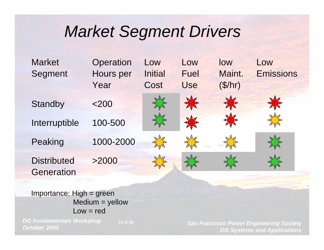
Market Segment Drivers
Market Operation Low Low low Low Segment Hours per Initial Fuel Maint. Emissions
Year Cost Use ($/hr)
Standby <200
Interruptible 100-500
Peaking 1000-2000
Distributed >2000Generation
Importance: High = greenMedium = yellowLow = red
DG Fundamentals WorkshopOctober 2003
San Francisco Power Engineering SocietyDG Systems and Applications
14 of 55
Economic Evaluation
Cost Benefit
Initial/Leased Costvs.
Lower Cost Power
Operating Cost Business Doesn’tfail with the power

DG Fundamentals WorkshopOctober 2003
San Francisco Power Engineering SocietyDG Systems and Applications
15 of 55
Emission level & air quality restrictions

DG Fundamentals WorkshopOctober 2003
San Francisco Power Engineering SocietyDG Systems and Applications
16 of 55
Emissions Requirements• There are no federal genset emissions standards for
stationary gensets• Local state or county regulations exist in air quality non-
attainment areas.– Often federal Mobile Off Highway (MOH) regulations
are adapted for diesel generators in non emergency standby applications >200 hr/yr.
• Many states have no specific genset emissions regulations– General site emissions permitting requirements apply– Typical solutions to issues are increasing exhaust
stack to increase dispersion
DG Fundamentals WorkshopOctober 2003
San Francisco Power Engineering SocietyDG Systems and Applications
17 of 55
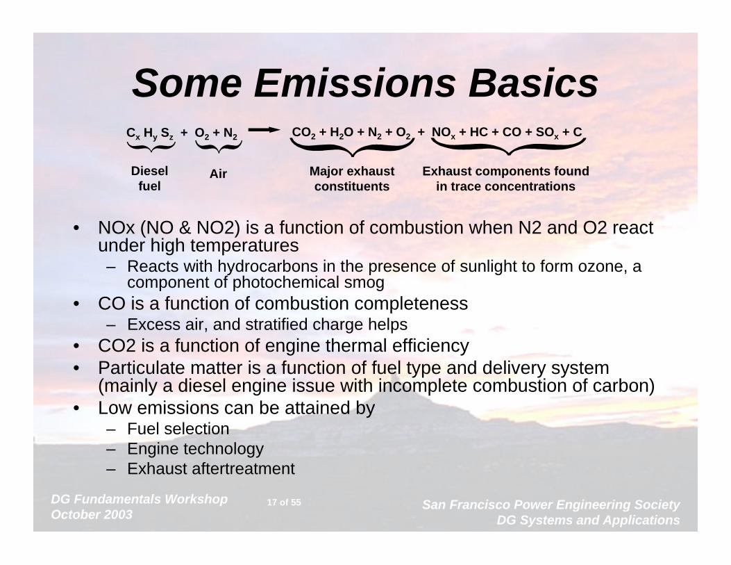
Some Emissions Basics
• NOx (NO & NO2) is a function of combustion when N2 and O2 react under high temperatures– Reacts with hydrocarbons in the presence of sunlight to form ozone, a
component of photochemical smog• CO is a function of combustion completeness
– Excess air, and stratified charge helps• CO2 is a function of engine thermal efficiency• Particulate matter is a function of fuel type and delivery system
(mainly a diesel engine issue with incomplete combustion of carbon)• Low emissions can be attained by
– Fuel selection– Engine technology– Exhaust aftertreatment
Cx Hy Sz + O2 + N2 CO2 + H2O + N2 + O2 + NOx + HC + CO + SOx + C
Dieselfuel
Air Major exhaustconstituents
Exhaust components foundin trace concentrations
DG Fundamentals WorkshopOctober 2003
San Francisco Power Engineering SocietyDG Systems and Applications
18 of 55
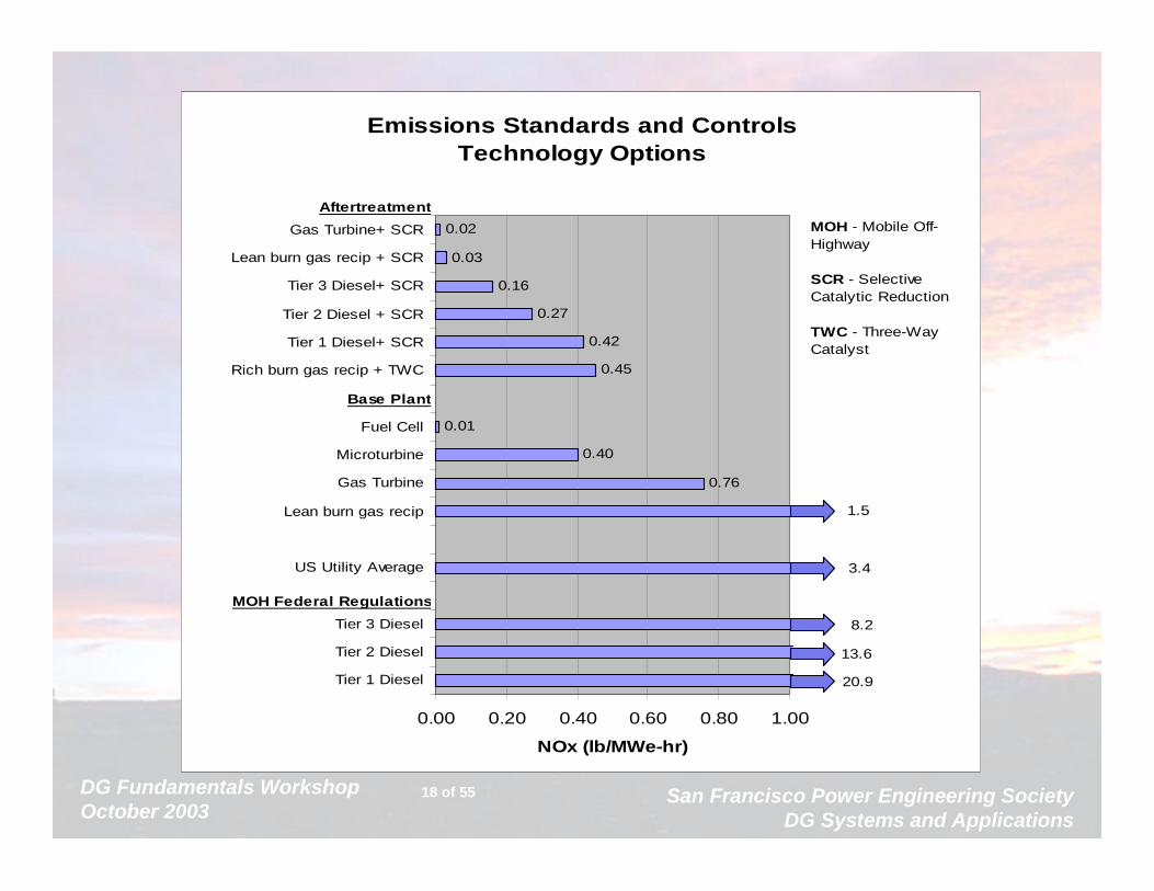
Emissions Standards and ControlsTechnology Options
0.76
0.40
0.01
0.45
0.42
0.27
0.16
0.03
0.02
13.6
20.9
8.2
3.4
1.5
0.00 0.20 0.40 0.60 0.80 1.00
Tier 1 Diesel
Tier 2 Diesel
Tier 3 Diesel
US Utility Average
Lean burn gas recip
Gas Turbine
Microturbine
Fuel Cell
Rich burn gas recip + TWC
Tier 1 Diesel+ SCR
Tier 2 Diesel + SCR
Tier 3 Diesel+ SCR
Lean burn gas recip + SCR
Gas Turbine+ SCR
NOx (lb/MWe-hr)
MOH Federal Regulations
Base Plant
AftertreatmentMOH - Mobile Off-Highway
SCR - Selective Catalytic Reduction
TWC - Three-Way Catalyst
DG Fundamentals WorkshopOctober 2003
San Francisco Power Engineering SocietyDG Systems and Applications
19 of 55
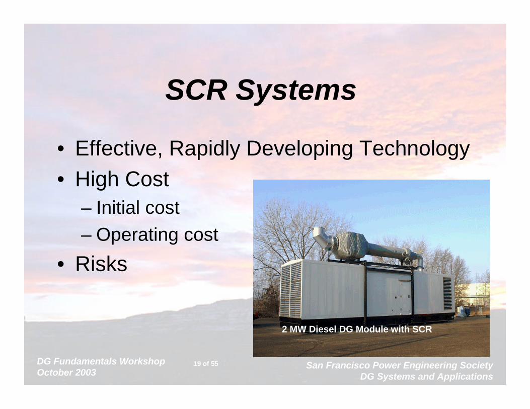
SCR Systems
• Effective, Rapidly Developing Technology• High Cost
– Initial cost– Operating cost
• Risks
2 MW Diesel DG Module with SCR
DG Fundamentals WorkshopOctober 2003
San Francisco Power Engineering SocietyDG Systems and Applications
20 of 55
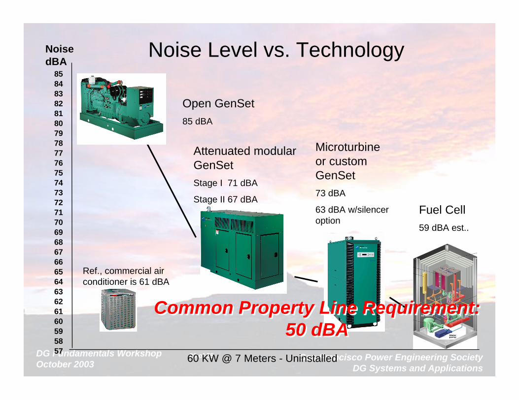
Noise dBA
8584838281807978777675747372717069686766656463626160595857
Noise Level vs. Technology
60 KW @ 7 Meters - Uninstalled
Microturbine or custom GenSet73 dBA
63 dBA w/silencer option
Attenuated modular GenSetStage I 71 dBA
Stage II 67 dBA
Open GenSet
85 dBA
Fuel Cell
59 dBA est..
Ref., commercial air conditioner is 61 dBA
Common Property Line Requirement:50 dBA
Common Property Line Requirement:50 dBA

DG Fundamentals WorkshopOctober 2003
San Francisco Power Engineering SocietyDG Systems and Applications
21 of 55
Hythane• Potential to introduce H2 using existing distribution and minorengine modifications
• 20% H2 and 80% NG can provide a 50% reduction in NOx emissions at equivalent efficiencies
Hydrogen
• Easily used in turbines and fuel cells
• Advance reciprocating engines can provide low emissions and good fuel economy
• Fuel cells provide an incremental improvement in fuel efficiency and emissions over turbines and reciprocating engines
•A challenge is to produce and distribute hydrogen at a commercially viable cost
DG Fundamentals WorkshopOctober 2003
San Francisco Power Engineering SocietyDG Systems and Applications
22 of 55
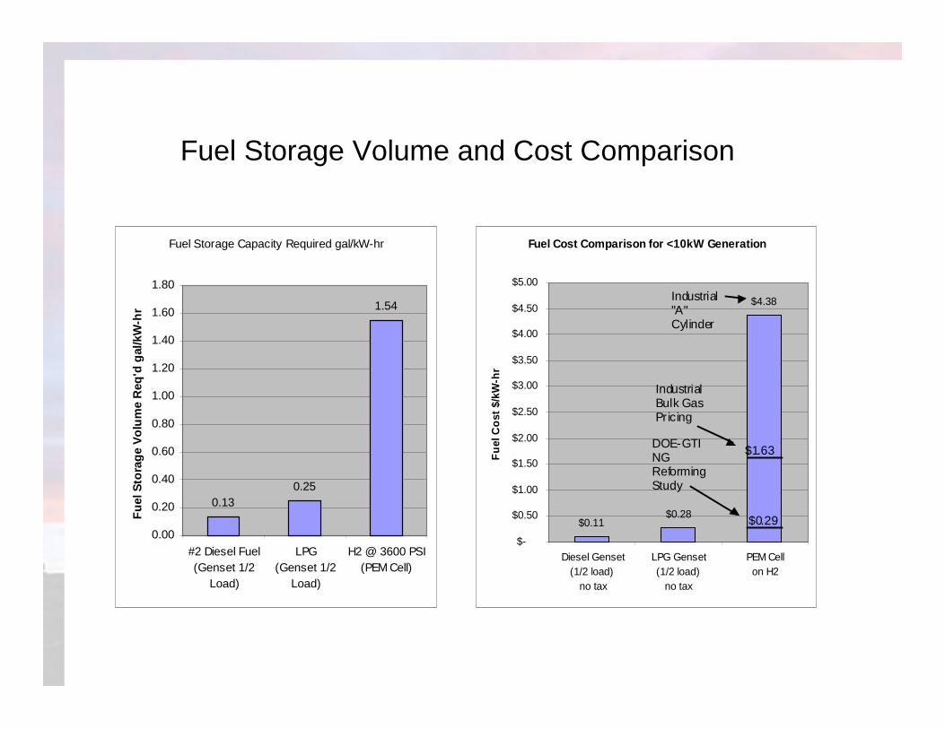
Fuel Storage Capacity Required gal/kW-hr
0.130.25
1.54
0.00
0.20
0.40
0.60
0.80
1.00
1.20
1.40
1.60
1.80
#2 Diesel Fuel(Genset 1/2
Load)
LPG(Genset 1/2
Load)
H2 @ 3600 PSI(PEM Cell)
Fu
el S
tora
ge
Vo
lum
e R
eq'd
gal
/kW
-hr
Fuel Cost Comparison for <10kW Generation
$0.11$0.28
$4.38
$-
$0.50
$1.00
$1.50
$2.00
$2.50
$3.00
$3.50
$4.00
$4.50
$5.00
Diesel Genset(1/2 load)
no tax
LPG Genset(1/2 load)
no tax
PEM Cell on H2
Fu
el C
ost
$/k
W-h
r
Industrial"A"Cylinder
IndustrialBulk GasPricing
DOE-GTINGReformingStudy
$1.63
$0.29
Fuel Storage Volume and Cost Comparison

DG Fundamentals WorkshopOctober 2003
San Francisco Power Engineering SocietyDG Systems and Applications
23 of 55
Fuel Cell Technologies
Germanischer Lloyd
DG Fundamentals WorkshopOctober 2003
San Francisco Power Engineering SocietyDG Systems and Applications
24 of 55
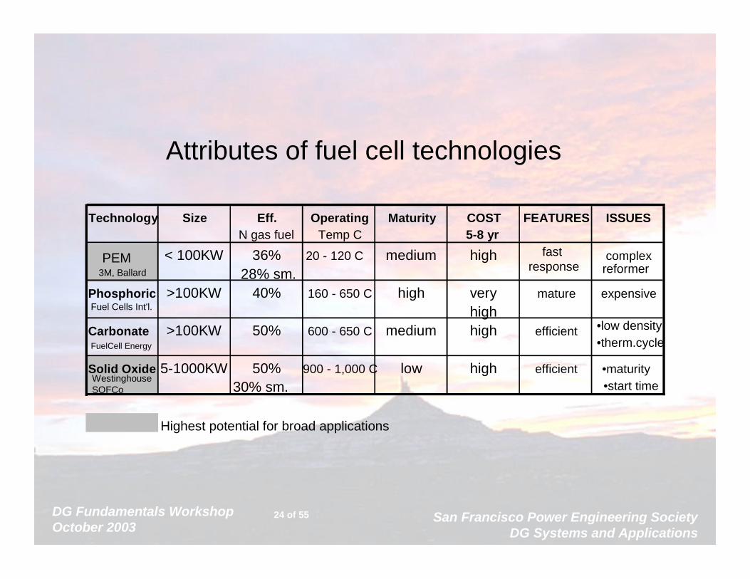
Attributes of fuel cell technologies
Technology Size Eff. Operating Maturity COST FEATURES ISSUESN gas fuel Temp C 5-8 yr
PEM < 100KW 36% 20 - 120 C medium high fast response
complex3M, Ballard 28% sm. reformer
Phosphoric >100KW 40% 160 - 650 C high very mature expensiveFuel Cells Int'l. highCarbonate >100KW 50% 600 - 650 C medium high efficient •low density
FuelCell Energy •therm.cycle
Solid Oxide 5-1000KW 50% 900 - 1,000 C low high efficient •maturity
30% sm.
Highest potential for broad applications
WestinghouseSOFCo •start time

DG Fundamentals WorkshopOctober 2003
San Francisco Power Engineering SocietyDG Systems and Applications
25 of 55
Gaseous Recip Fuel Engines• Stoichiometric Engines
– Carburated, spark plug ignition
• Lean Burn Engines– Close fuel/air ratio control, spark ignited
• Fumigation Techniques– Diesel start and pilot ignition, gas induction– 5% diesel in operation = lower maintenance
• High Pressure Injection – Higher power (+30%), efficiency (+2%)– Lower emissions (1/2 g/bhp-hr NOx w/o aftertreat)

DG Fundamentals WorkshopOctober 2003
San Francisco Power Engineering SocietyDG Systems and Applications
26 of 55
Natural Gas Jet
Direct Gas Injection Technology
• Gas is compressed on the engine and Injected in the cylinder at 3600psi
• Diesel fuel is injected to initiate combustion (approx.. 5% of fuel)
• The lean gas/air mixture burns to completion
A

DG Fundamentals WorkshopOctober 2003
San Francisco Power Engineering SocietyDG Systems and Applications
27 of 55
Microturbine Manufactures
Elliott 45 kW SystemNREC 80 kW System
Cummins Power Generation
30KW and 60 KW Systems
DG Fundamentals WorkshopOctober 2003
San Francisco Power Engineering SocietyDG Systems and Applications
28 of 55
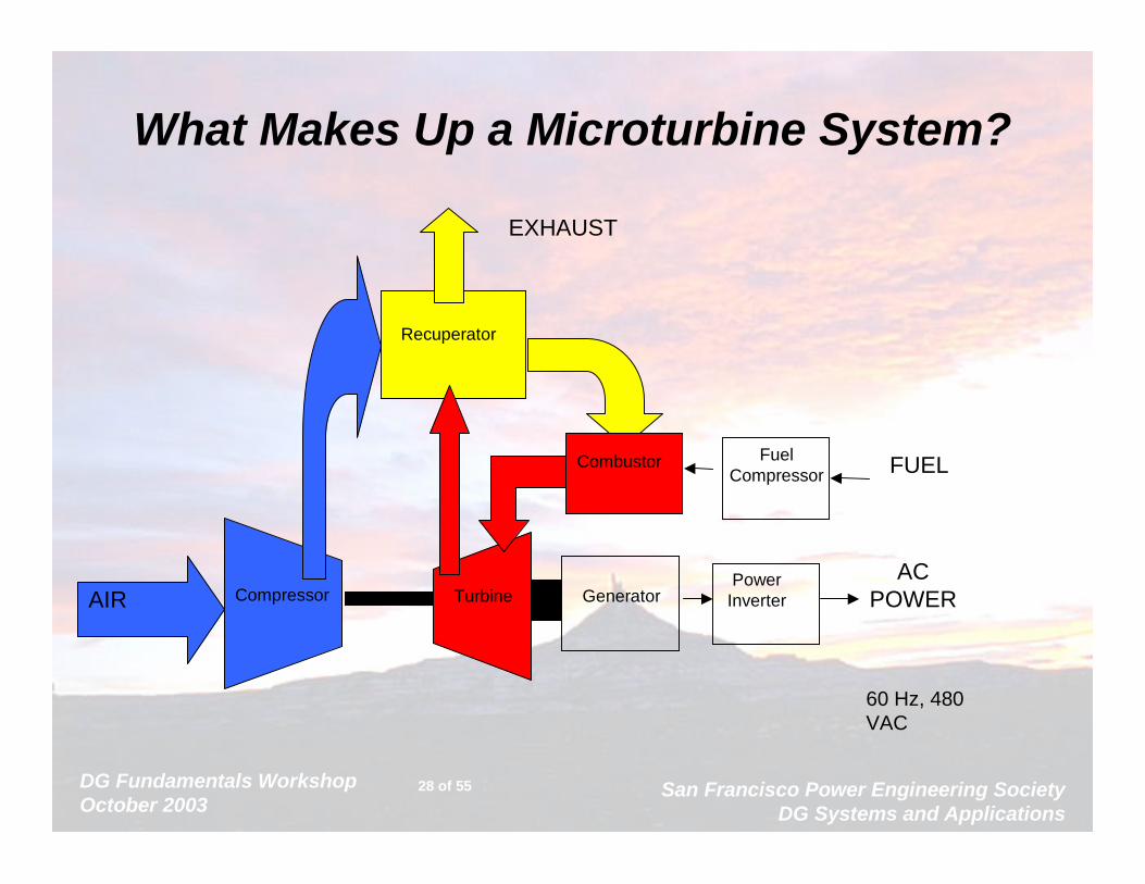
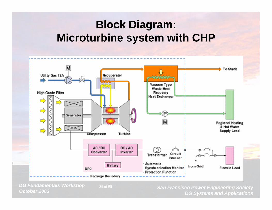
What Makes Up a Microturbine System?
Compressor Turbine Generator
Combustor
Recuperator
FUEL
AIR
EXHAUST
Power Inverter
AC POWER
Fuel Compressor
60 Hz, 480 VAC
DG Fundamentals WorkshopOctober 2003
San Francisco Power Engineering SocietyDG Systems and Applications
29 of 55
Block Diagram: Microturbine system with CHP
DG Fundamentals WorkshopOctober 2003
San Francisco Power Engineering SocietyDG Systems and Applications
30 of 55
Integrating DG into a SiteNew Systems:
– Traditional Practical Limit for Synchronous Generator Sets: >600A
• New breaker and control technologies make “electrically” practical down to approx. 200A
– NO DISTURBANCE• Soft Transfer Systems
» Hard closed transition doesn’t work• Paralleling/Soft Transfer Systems
» To stay connected, or not: that is the question...– Cogen/Renewable any size
• Retrofit Systems– Paralleling and Large Generator Sets
DG Fundamentals WorkshopOctober 2003
San Francisco Power Engineering SocietyDG Systems and Applications
31 of 55
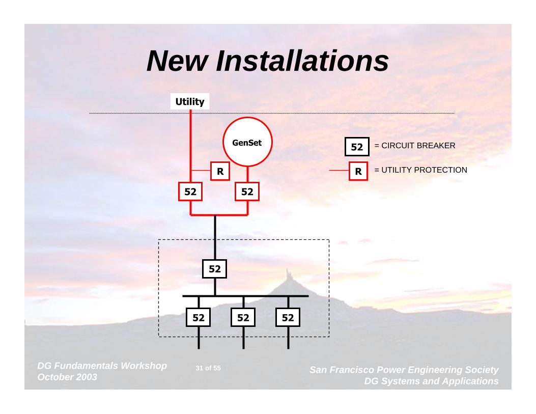
New Installations
GenSet
52 52
Utility
R
52
52 52 52
52 = CIRCUIT BREAKER
R = UTILITY PROTECTION
DG Fundamentals WorkshopOctober 2003
San Francisco Power Engineering SocietyDG Systems and Applications
32 of 55
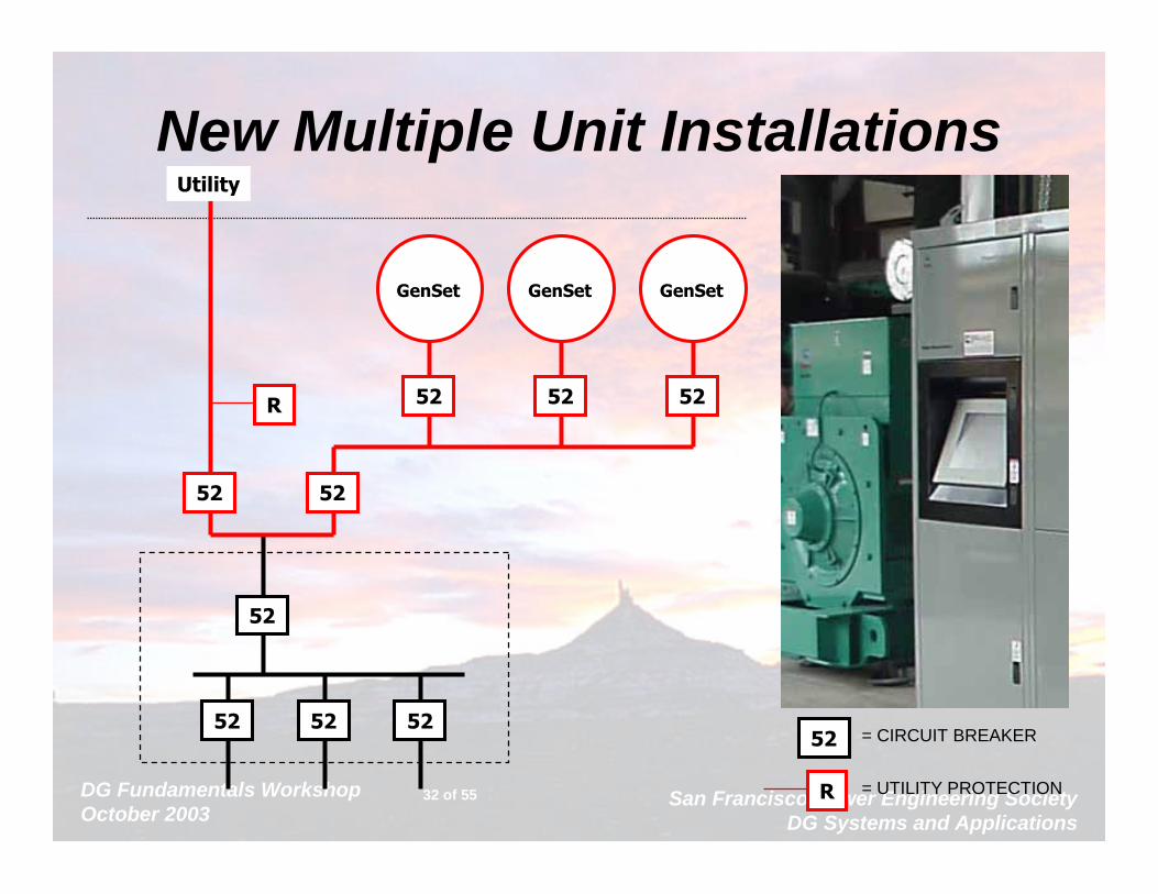
New Multiple Unit Installations
52
52 52 52
52 52
Utility
R
GenSet
52
GenSet
52
GenSet
52
52 = CIRCUIT BREAKER
R = UTILITY PROTECTION

DG Fundamentals WorkshopOctober 2003
San Francisco Power Engineering SocietyDG Systems and Applications
33 of 55
Typical Small DG or CHP
GenSet52
Utility
R
52
52 52 52
52 = CIRCUIT BREAKER
R = UTILITY PROTECTION

DG Fundamentals WorkshopOctober 2003
San Francisco Power Engineering SocietyDG Systems and Applications
34 of 55
Retrofit: Single Generator Set
GenSet
52 52 52
52
52 52 52
ATS
ATS
ATS
52R
Utility
52
CRITICAL LOADS
CRITICAL LOADS
CRITICAL LOADS
52

DG Fundamentals WorkshopOctober 2003
San Francisco Power Engineering SocietyDG Systems and Applications
35 of 55
Retrofit: Multiple Gensets
GenSet
52 52 52
52
52 52 52
ATS
ATS
ATS
52R
Utility
52
CRITICAL LOADS
CRITICAL LOADS
CRITICAL LOADS
GenSet
52
DG Fundamentals WorkshopOctober 2003
San Francisco Power Engineering SocietyDG Systems and Applications
36 of 55
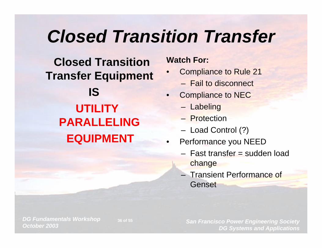
Closed Transition TransferClosed Transition
Transfer Equipment IS
UTILITY PARALLELING
EQUIPMENT
Watch For:• Compliance to Rule 21
– Fail to disconnect• Compliance to NEC
– Labeling– Protection– Load Control (?)
• Performance you NEED– Fast transfer = sudden load
change– Transient Performance of
Genset
DG Fundamentals WorkshopOctober 2003
San Francisco Power Engineering SocietyDG Systems and Applications
37 of 55
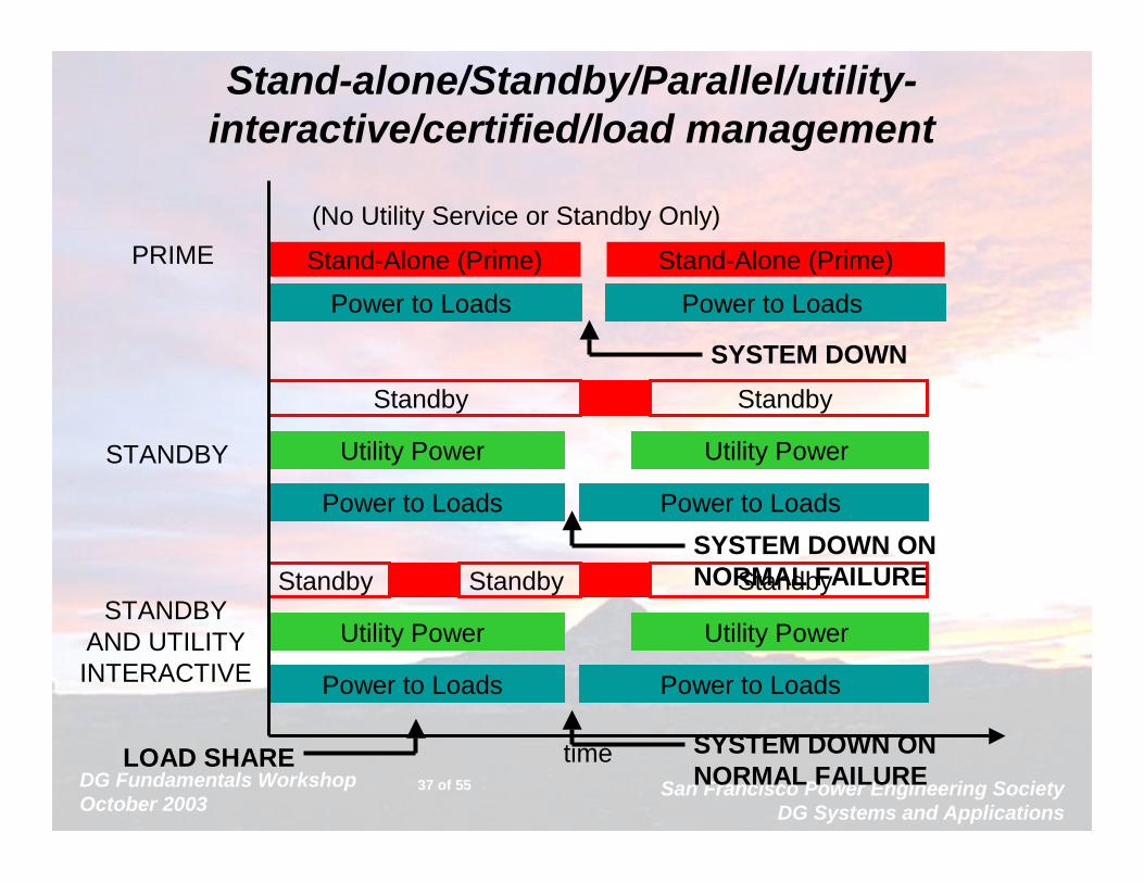
Standby Standby
Utility Power Utility Power
Power to Loads Power to Loads
Standby
Stand-alone/Standby/Parallel/utility-interactive/certified/load management
Stand-Alone (Prime) Stand-Alone (Prime)
(No Utility Service or Standby Only)
Power to Loads Power to Loads
Standby Standby
Utility Power Utility Power
Power to Loads Power to Loads
time
PRIME
STANDBY
STANDBYAND UTILITYINTERACTIVE
SYSTEM DOWN
SYSTEM DOWN ON NORMAL FAILURE
SYSTEM DOWN ON NORMAL FAILURE
LOAD SHARE

DG Fundamentals WorkshopOctober 2003
San Francisco Power Engineering SocietyDG Systems and Applications
38 of 55
System ProtectionGG G
12470 V
480 V
40004000
2000(TYP 3)
GENERATORPROTECTION
SWITCHGEAR &FEEDER PROTECTION
UTILITYPROTECTION

DG Fundamentals WorkshopOctober 2003
San Francisco Power Engineering SocietyDG Systems and Applications
39 of 55
Generator Protection• I/O availability in digital controls
makes anything possible• Difficulty of:
Protection vs. Reliability• Protection Tuned for the Generator
– Overcurrent– Over/Under Voltage– Over/Under Frequency– Loss of Field/Reverse Power– Differential
POWERTO
LOAD
EN
GIN
E
GEN
EC
GOV
AVR
CB
REMOTE

DG Fundamentals WorkshopOctober 2003
San Francisco Power Engineering SocietyDG Systems and Applications
40 of 55
Control and Protective FunctionsGENSET
AM SW
VM SW
KW KWH PF 40 32 65 90 51V
HZ 27 81U 59
SU
RG
E S
UP
PR
ES
SO
RS
VM SW HZ 47 SYNC 2586
SSDIGITAL CONTROL
SWITCHGEAR TRIP
CLOSE

DG Fundamentals WorkshopOctober 2003
San Francisco Power Engineering SocietyDG Systems and Applications
41 of 55
Utility Protection• Design Depends
on:– Local conditions
– Codes and Standards
– Utility Practice
– More Variety than Generator
• Common Protective Devices:– Over/Under Volts,
Hz
– Reverse Power– Directional Current
• Distribution Changes
DG Fundamentals WorkshopOctober 2003
San Francisco Power Engineering SocietyDG Systems and Applications
42 of 55
Voltage Regulation/Frequency Regulation
• To the generator guy:– The difference between steady state no load
and full load voltage or frequency, as a percentage of nominal level
– Describes how well the machine can maintain nominal levels over time
– Typical: +1% for voltage, +0.25% for Hz
• To a utility:– An attempt by a device to change the voltage
or frequency of the utility service

DG Fundamentals WorkshopOctober 2003
San Francisco Power Engineering SocietyDG Systems and Applications
43 of 55
Synchronous Generator Control
• Active Controls include:– Governor
• Measures speed • Controls fuel rate
– AVR• Measures voltage• Controls excitation (field strength)
• Both work like a cruise control
POWERTO
LOAD
EN
GIN
E
GEN
EC
GOV
AVR
CB
REMOTE
DG Fundamentals WorkshopOctober 2003
San Francisco Power Engineering SocietyDG Systems and Applications
44 of 55
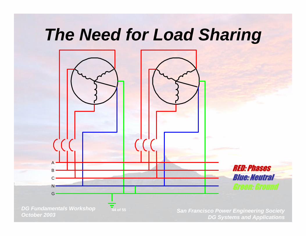
The Need for Load Sharing
RED: PhasesRED: PhasesBlue: NeutralBlue: NeutralGreen: GroundGreen: Ground
A
B
C
N
G

DG Fundamentals WorkshopOctober 2003
San Francisco Power Engineering SocietyDG Systems and Applications
45 of 55
Intertied Synchronous Generator Control System
POWERTO
LOAD
EN
GIN
E
GEN
EC
GOV
AVR
CB
REMOTE
ILSSYNCPROTMETER
ALARMLOAD SHARE
DATA
I/E VAR/PF
UTILITY/MAINS
CB
25
PROT
SENSELOGIC
DG Fundamentals WorkshopOctober 2003
San Francisco Power Engineering SocietyDG Systems and Applications
46 of 55
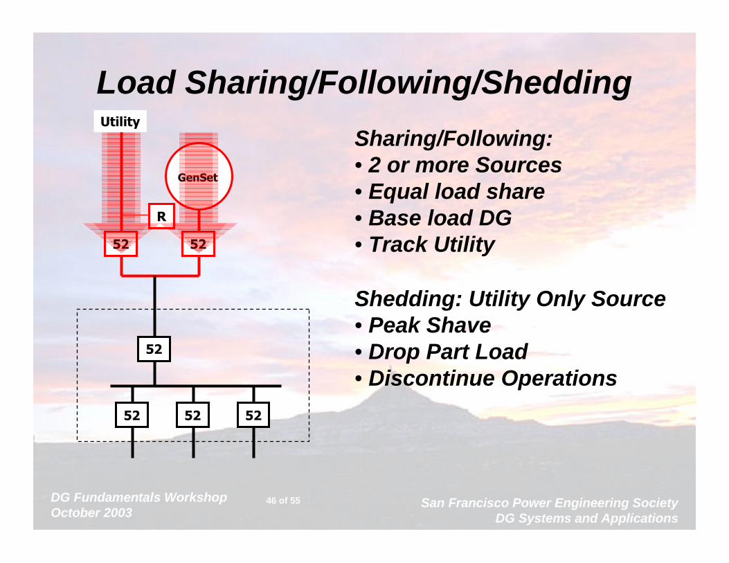
Load Sharing/Following/Shedding
GenSet
52 52
Utility
R
52
52 52 52
Sharing/Following: • 2 or more Sources• Equal load share • Base load DG• Track Utility
Shedding: Utility Only Source • Peak Shave • Drop Part Load• Discontinue Operations

DG Fundamentals WorkshopOctober 2003
San Francisco Power Engineering SocietyDG Systems and Applications
47 of 55
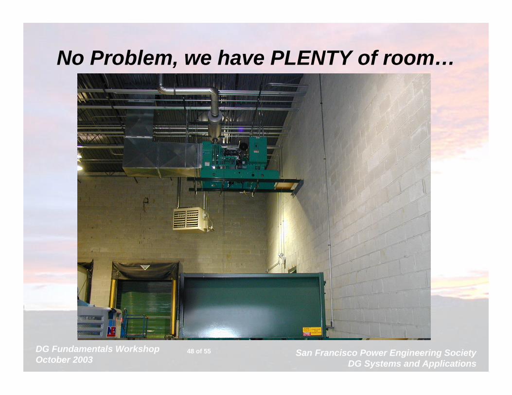
Mechanical Considerations• Where are you going to put it?• Mechanical Issues
– Getting waste heat out– Using as much as practical
– Exhaust– Vibration/Noise
– Fuel Storage and System Design
DG Fundamentals WorkshopOctober 2003
San Francisco Power Engineering SocietyDG Systems and Applications
48 of 55
No Problem, we have PLENTY of room…
DG Fundamentals WorkshopOctober 2003
San Francisco Power Engineering SocietyDG Systems and Applications
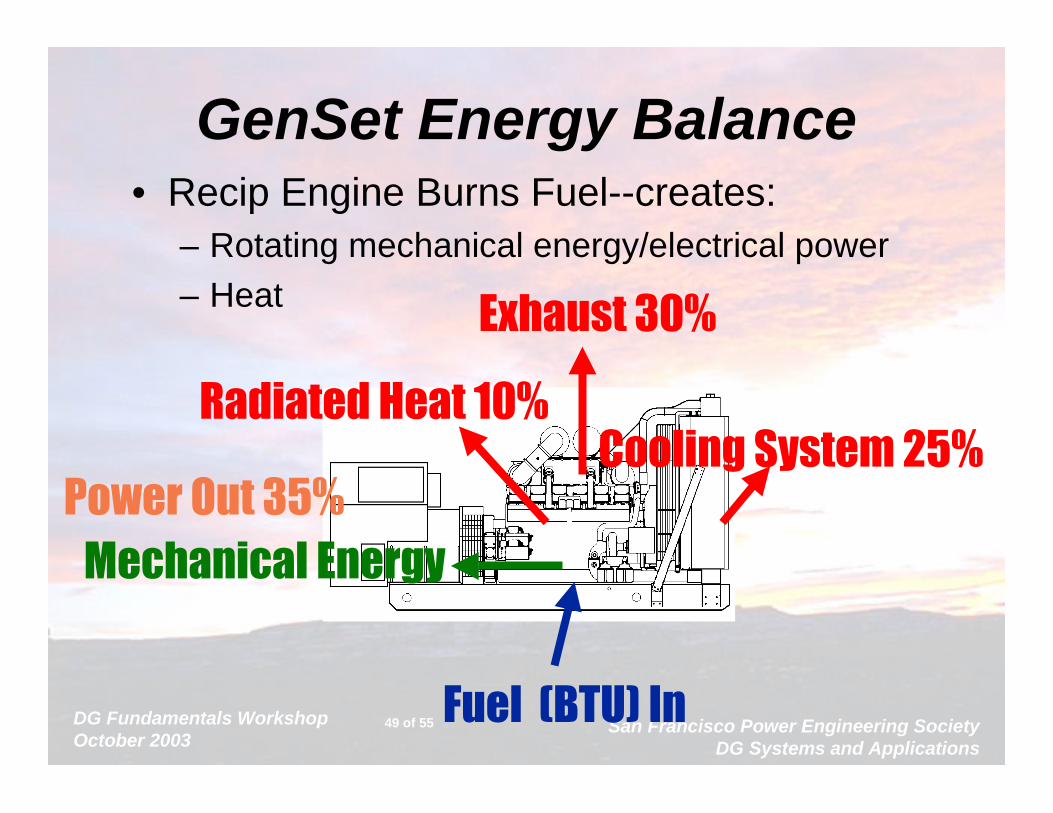
49 of 55
GenSet Energy Balance• Recip Engine Burns Fuel--creates:
– Rotating mechanical energy/electrical power– Heat
Fuel (BTU) In
Mechanical Energy
Radiated Heat 10%Cooling System 25%
Exhaust 30%
Power Out 35%
DG Fundamentals WorkshopOctober 2003
San Francisco Power Engineering SocietyDG Systems and Applications
50 of 55
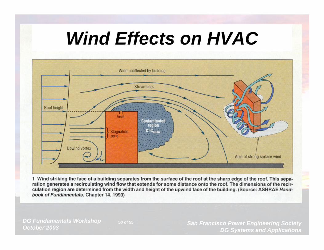
Wind Effects on HVAC

DG Fundamentals WorkshopOctober 2003
San Francisco Power Engineering SocietyDG Systems and Applications
51 of 55
Noise Concerns130 Pneumatic Riveter (130)
120 110
100 Jet @ 1000ft (103)
90 Power Mower (96)80 Heavy Street Traffic (85)
70
60 Normal Conversation (65)
50 Light Traffic @ 100ft (55)40 Library (40)
30
20 Broadcast Studio (20)
2000KWGenset Range
50KW
• Noise Ordinances Strict
• Noise Levels of Many DG High
• Cost of Noise Treatment is High– Particularly if you screw up
• Uncertain Enforcement

DG Fundamentals WorkshopOctober 2003
San Francisco Power Engineering SocietyDG Systems and Applications
52 of 55
Fuel Storage…
DG Fundamentals WorkshopOctober 2003
San Francisco Power Engineering SocietyDG Systems and Applications
53 of 55
Big Things to Remember…• Best technology for a site depends on:
– Fuel availability, cost– Emissions Restrictions– Efficiency– Mechanical Concerns
• There is no one best technology that will work for every site
• Technology is driving costs down, so owners need to keep watching for opportunities
DG Fundamentals WorkshopOctober 2003
San Francisco Power Engineering SocietyDG Systems and Applications
54 of 55
Prognosis• DG will grow
– Big Incentives Nationally– Economic viability to User
• Risk needs to be reduced
• Success depends on – Planning – Cooperative Venture between:
• User• Developer/Supplier• Utility• Regulators
DG Fundamentals WorkshopOctober 2003
San Francisco Power Engineering SocietyDG Systems and Applications
55 of 55
Questions?
Gary OlsonCummins Power Generation

Effects of Generation on Radial Distribution Feeders
An IEEE PresentationOctober 18, 2003
San Francisco State University
By
Mohammad Vaziri, Ph.D., P.E.

October 18, 2003 Distributed Generation CourseSan Francisco Power Engineering Society
2 of 21
Generation Effects on:
A) Planning & Design
• Feeder Loading• Voltage Regulators (Steady State)• Voltage Flicker (Transient)
• Capacitor Controls• Stability concerns
October 18, 2003 Distributed Generation CourseSan Francisco Power Engineering Society
3 of 21
B) System Protection
• Overstress on equipment• Protective equipment desensitization
• Islanding Conditions• Ferro-resonance
• Nuisance Tripping

October 18, 2003 Distributed Generation CourseSan Francisco Power Engineering Society
4 of 21
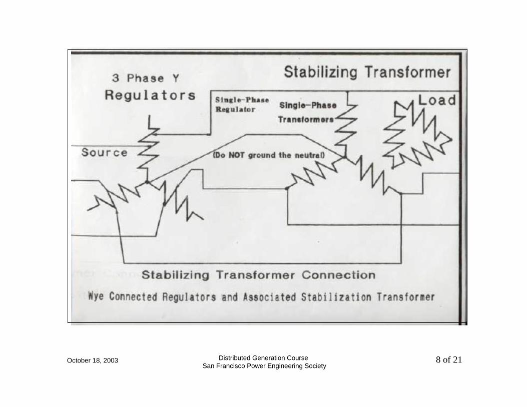
"Comparison of "Open Delta" and "Closed Delta" Distribution Line Regulators.
1 - Phasor Diagram for the "Open-Delta" regulators shows the Neutral Shift associated with Open Delta
regulators under "Full 10% Boost" condition.
2 - Phasor Diagram for the Closed Delta regulators shows the derivation of the 15% regulation capability (
under full boost condition) when the 10% regulators are connected in a Closed Delta configuration.
October 18, 2003 Distributed Generation CourseSan Francisco Power Engineering Society
5 of 21
A
A’
B
B’
100%
110%
C C’
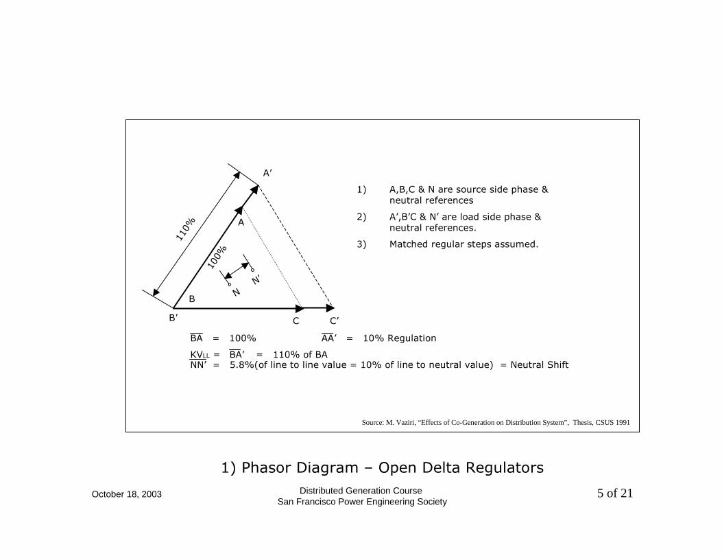
1) A,B,C & N are source side phase & neutral references
2) A’,B’C & N’ are load side phase & neutral references.
3) Matched regular steps assumed.
BA = 100% AA’ = 10% Regulation
KVLL = BA’ = 110% of BANN’ = 5.8%(of line to line value = 10% of line to neutral value) = Neutral Shift
N N’
1) Phasor Diagram – Open Delta Regulators
Source: M. Vaziri, “Effects of Co-Generation on Distribution System”, Thesis, CSUS 1991
October 18, 2003 Distributed Generation CourseSan Francisco Power Engineering Society
6 of 21
A
A’
B
B’
100%
115%
C C’
0.1
1.0
N, °N’X°
C’
c = 1.15
a = 1.1
A
A’b = 0.1
120°
BA = 100% AA’ = 10%
KVLL = B’A’ = 115%NN’ = 0 Neutral Shift
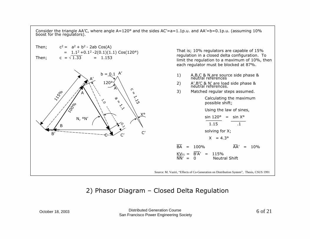
Consider the triangle AA’C, where angle A=120° and the sides AC’=a=1.1p.u. and AA’=b=0.1p.u. (assuming 10% boost for the regulators).
1) A,B,C & N are source side phase & neutral references
2) A’,B’C & N’ are load side phase & neutral references.
3) Matched regular steps assumed.
Calculating the maximum possible shift;
Using the law of sines,
sin 120° = sin X°
1.15 .1
solving for X;
X = 4.3°
Then; c2 = a2 + b2 - 2ab Cos(A)= 1.12 +0.12 -2(0.1)(1.1) Cos(120°)
Then; c = √ 1.33 = 1.153
That is; 10% regulators are capable of 15% regulation in a closed delta configuration. To limit the regulation to a maximum of 10%, then each regulator must be blocked at 87%.
2) Phasor Diagram – Closed Delta Regulation
Source: M. Vaziri, “Effects of Co-Generation on Distribution System”, Thesis, CSUS 1991
October 18, 2003 Distributed Generation CourseSan Francisco Power Engineering Society
7 of 21
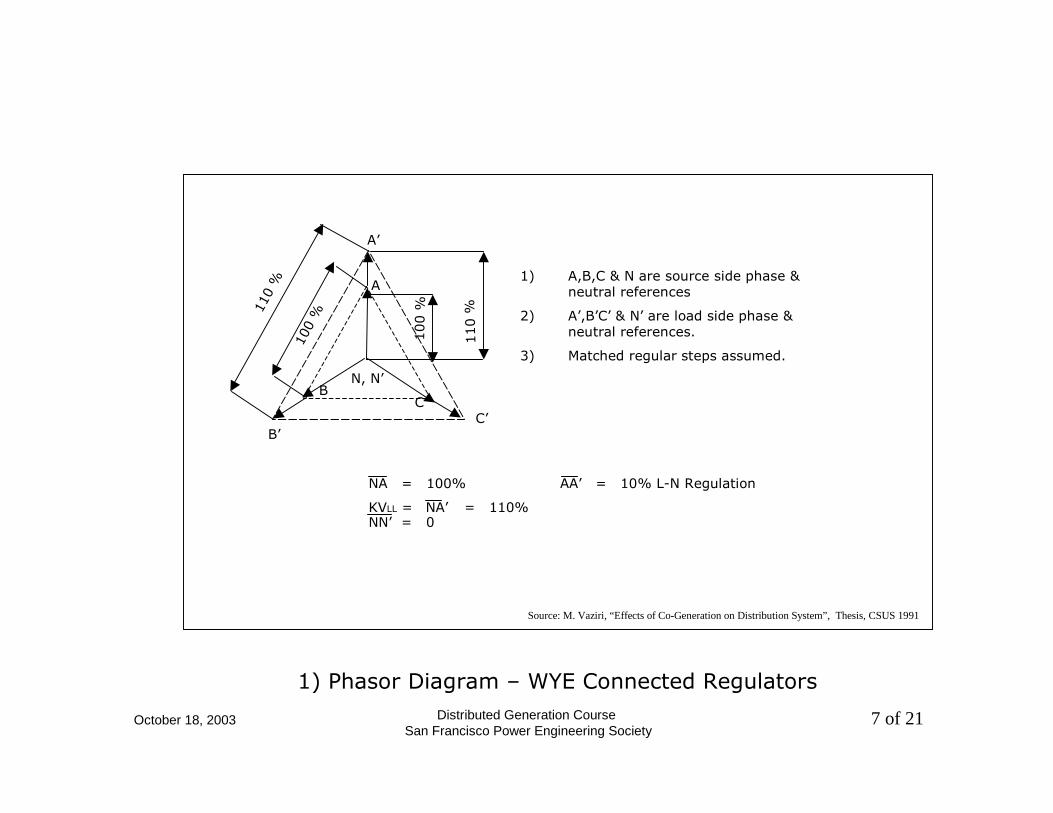
1) A,B,C & N are source side phase & neutral references
2) A’,B’C’ & N’ are load side phase & neutral references.
3) Matched regular steps assumed.
NA = 100% AA’ = 10% L-N Regulation
KVLL = NA’ = 110% NN’ = 0
1) Phasor Diagram – WYE Connected Regulators
Source: M. Vaziri, “Effects of Co-Generation on Distribution System”, Thesis, CSUS 1991
100
%110
%
100 %
110 %
B’
A’
C’
B
A
C
N, N’
October 18, 2003 Distributed Generation CourseSan Francisco Power Engineering Society
8 of 21

October 18, 2003 Distributed Generation CourseSan Francisco Power Engineering Society
9 of 21

October 18, 2003 Distributed Generation CourseSan Francisco Power Engineering Society
10 of 21
Thevenin Equivalent of sequence networks at resonance neglecting resistance
October 18, 2003 Distributed Generation CourseSan Francisco Power Engineering Society
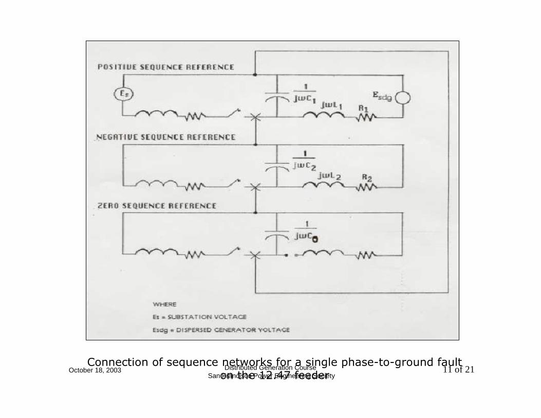
11 of 21Connection of sequence networks for a single phase-to-ground fault
on the 12.47 feeder
October 18, 2003 Distributed Generation CourseSan Francisco Power Engineering Society
12 of 21
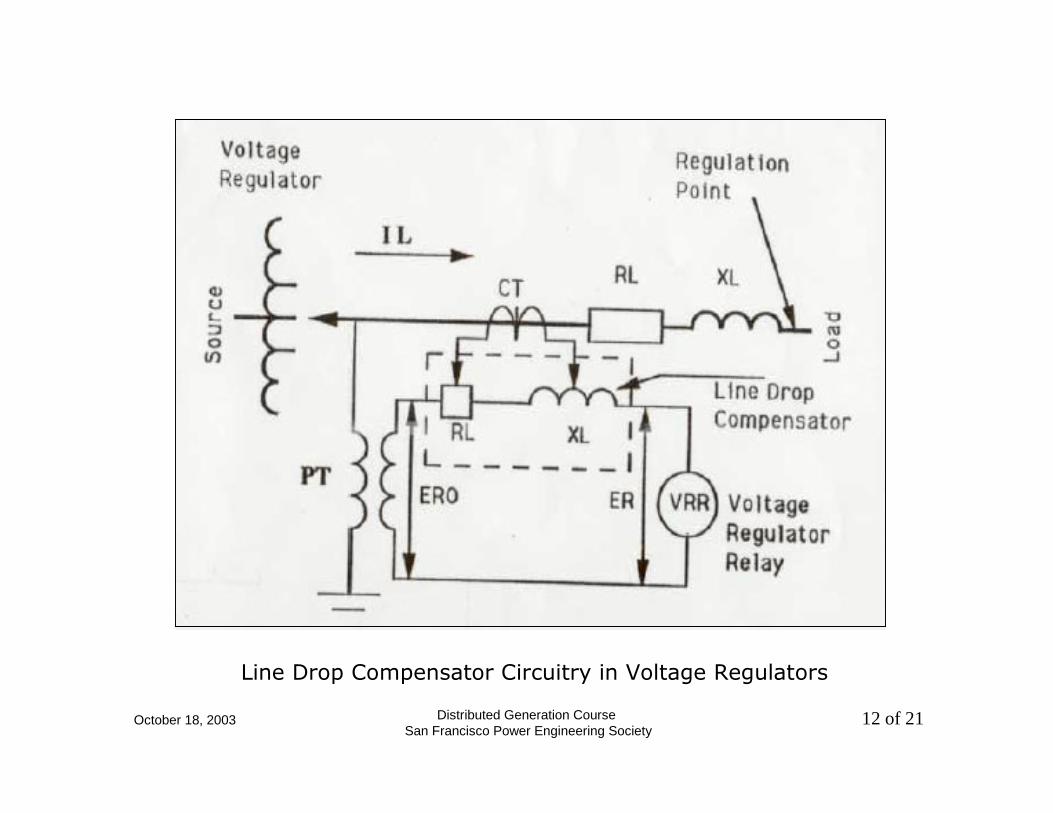
Line Drop Compensator Circuitry in Voltage Regulators
October 18, 2003 Distributed Generation CourseSan Francisco Power Engineering Society
13 of 21
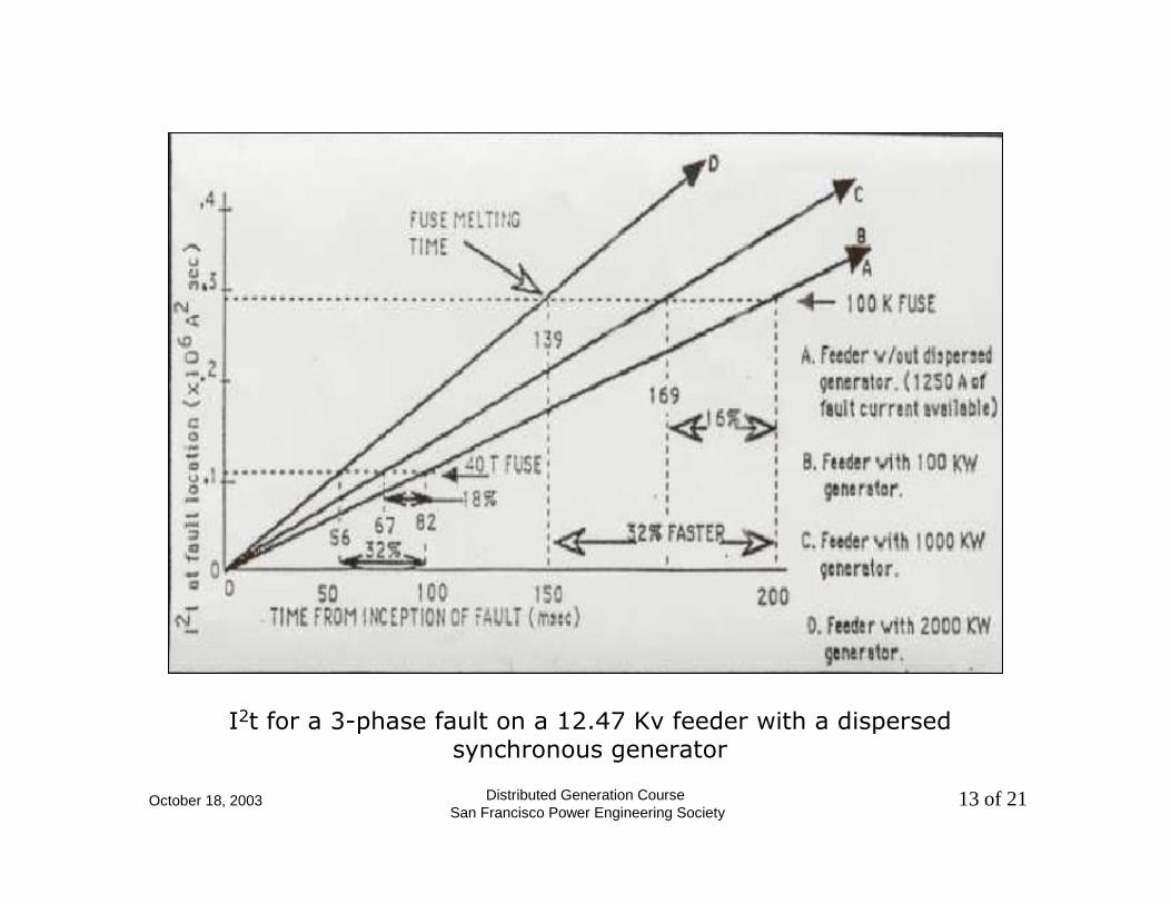
I2t for a 3-phase fault on a 12.47 Kv feeder with a dispersed synchronous generator
October 18, 2003 Distributed Generation CourseSan Francisco Power Engineering Society
14 of 21
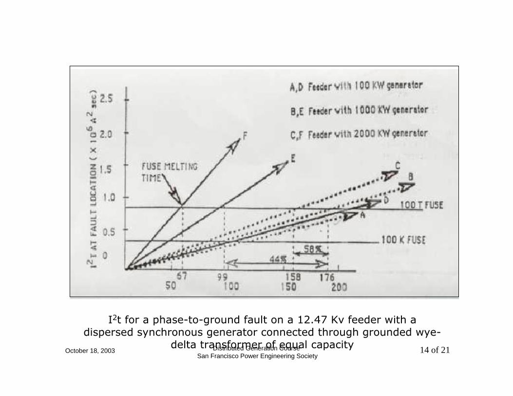
I2t for a phase-to-ground fault on a 12.47 Kv feeder with a dispersed synchronous generator connected through grounded wye-
delta transformer of equal capacity
October 18, 2003 Distributed Generation CourseSan Francisco Power Engineering Society
15 of 21
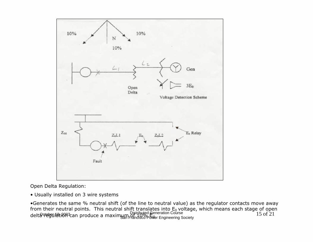
Open Delta Regulation:
• Usually installed on 3 wire systems
•Generates the same % neutral shift (of the line to neutral value) as the regulator contacts move away from their neutral points. This neutral shift translates into E0 voltage, which means each stage of open delta regulation can produce a maximum of 10% E0.
October 18, 2003 Distributed Generation CourseSan Francisco Power Engineering Society
16 of 21
fault
~ 10%
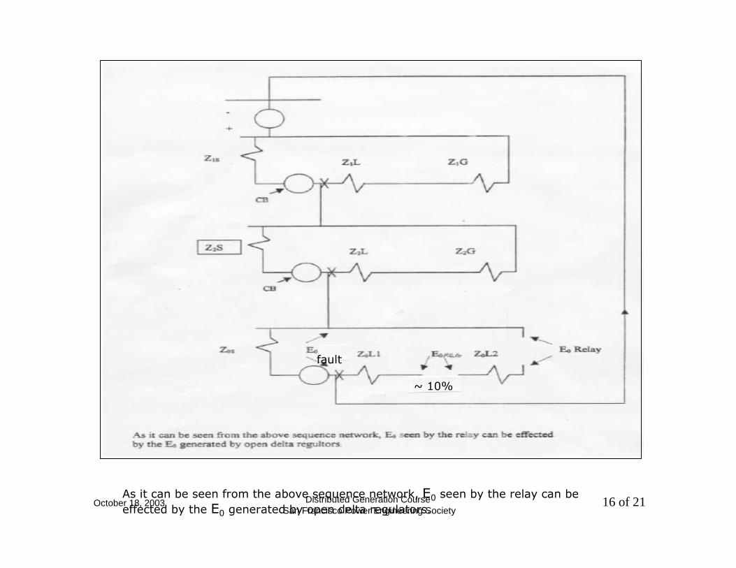
As it can be seen from the above sequence network, E0 seen by the relay can be effected by the E0 generated by open delta regulators.

October 18, 2003 Distributed Generation CourseSan Francisco Power Engineering Society
17 of 21
Coordination Against Nuisance Tripping
Single Line, Positive, Negative, and Zero Sequence Diagram

October 18, 2003 Distributed Generation CourseSan Francisco Power Engineering Society
18 of 21
Coordination Against Nuisance Tripping Using Xd’
Three Phases and Three Io Currents for Faults at F2

October 18, 2003 Distributed Generation CourseSan Francisco Power Engineering Society
19 of 21
Desensetization of Recloser R1 after Interconnection of SDG
Three Phases Io Currents for Faults at F1
Grounded Y- Connection for SDG Main Transformer is assumed
October 18, 2003 Distributed Generation CourseSan Francisco Power Engineering Society
20 of 21
References
1) Mohamad Y. Vaziri P.E., “Effects of GO Generation on Distribution System”, M.S.EE Thesis CSUS 1991
2) Richard M. Moffatt, Customer Generation on the Distribution System. Presented at the 34th Annual Conference for Protective Relay Engineers, Texas A&M University, Collage Station, Texas. April 13-18, 1981.
3) Roger C. Dugan and Dwight T. Rizy, “Electric Distribution Protection Problems Associated with the Interconnection of Small, Dispersed Generation Devices”. IEEE Transactions on Power Apparatus and Systems, PAS-103 No. 6 June 1984
October 18, 2003 Distributed Generation CourseSan Francisco Power Engineering Society
21 of 21
4) N.H. Malik, and A.A. Mazi, “Capacitance Requirements for Isolated Self-Excited Induction Generators”, IEEE Transactions on Power Systems 86 WM 219-0 pp. 62-69, March 1987
5) Robert H. Jones, Measuring the Effects of Dispersed Generation, Rochester Gas and Electric Company. Published by Transmission & Distribution, a Cleworth Publication, pp. 50-54, August 1987.


EENNDDEE CCOONNEE NN GG II NN EE EE RR II NN GG
Distributed Generation Distributed Generation Interconnection Interconnection
Standards & GuidelinesStandards & GuidelinesChuck WhitakerChuck Whitaker
Endecon EngineeringEndecon Engineering
IEEE San Francisco PES DG Fundamentals WorkshopIEEE San Francisco PES DG Fundamentals WorkshopSan Francisco State UniversitySan Francisco State University
October 18, 2003October 18, 2003

October 18, 2003Distributed Generation Course
2 of 97San Francisco Power Engineering SocietyEENNDDEE CCOONN
EE NN GG II NN EE EE RR II NN GG
Interconnection Standards & GuidelinesInterconnection Standards & Guidelines
•• Regulatory Agency Interconnection Rules Regulatory Agency Interconnection Rules –– MuniMuni Boards, State Boards, State PUCsPUCs (i.e.(i.e. Rule 21Rule 21), FERC ), FERC
•• Equipment and Facility Requirement Standards Equipment and Facility Requirement Standards –– IEEE 929, IEEE 1547, IEEE 1547.2IEEE 929, IEEE 1547, IEEE 1547.2
•• Product Testing StandardsProduct Testing Standards–– UL1741UL1741, UL2200, IEEE C37.X , , UL2200, IEEE C37.X , IEEE P1547.1,IEEE P1547.1, NEMA, NEMA,
etc.etc.
October 18, 2003Distributed Generation Course
3 of 97San Francisco Power Engineering SocietyEENNDDEE CCOONN
EE NN GG II NN EE EE RR II NN GG
Presentation OverviewPresentation Overview
•• California Electric Rule 21California Electric Rule 21
•• IEEE 929IEEE 929
•• IEEE 1547 FamilyIEEE 1547 Family–– 15471547
–– 1547.11547.1
–– 1547.21547.2
•• UL 1741UL 1741
October 18, 2003Distributed Generation Course
4 of 97San Francisco Power Engineering SocietyEENNDDEE CCOONN
EE NN GG II NN EE EE RR II NN GG
California Electric Rule 21California Electric Rule 21
Standard for Interconnecting Standard for Interconnecting Distributed Resources with Electric Distributed Resources with Electric
Power Systems Power Systems
(Thanks to Scott Tomashefsky)(Thanks to Scott Tomashefsky)

October 18, 2003Distributed Generation Course
5 of 97San Francisco Power Engineering SocietyEENNDDEE CCOONN
EE NN GG II NN EE EE RR II NN GG
•• A term commonly referred to as interconnection A term commonly referred to as interconnection rules.rules.
•• Specific rule contained in the electricity tariff Specific rule contained in the electricity tariff booklets of the utilities under CPUC jurisdiction.booklets of the utilities under CPUC jurisdiction.
•• Documentation of technical and procedural criteria Documentation of technical and procedural criteria for connecting generation equipment to the utility for connecting generation equipment to the utility systems.systems.
•• Technology and size neutral. Technology and size neutral.
What Is Rule 21?What Is Rule 21?
October 18, 2003Distributed Generation Course
6 of 97San Francisco Power Engineering SocietyEENNDDEE CCOONN
EE NN GG II NN EE EE RR II NN GG
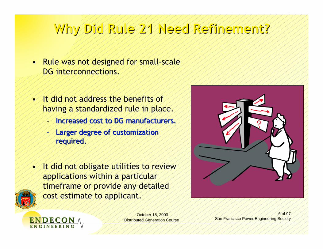
•• Rule was not designed for smallRule was not designed for small--scale scale DG interconnections.DG interconnections.
•• It did not address the benefits of It did not address the benefits of having a standardized rule in place.having a standardized rule in place.–– Increased cost to DG manufacturers.Increased cost to DG manufacturers.
–– Larger degree of customization Larger degree of customization required.required.
•• It did not obligate utilities to review It did not obligate utilities to review applications within a particular applications within a particular timeframe or provide any detailed timeframe or provide any detailed cost estimate to applicant.cost estimate to applicant.
Why Did Rule 21 Need Refinement?Why Did Rule 21 Need Refinement?
October 18, 2003Distributed Generation Course
7 of 97San Francisco Power Engineering SocietyEENNDDEE CCOONN
EE NN GG II NN EE EE RR II NN GG
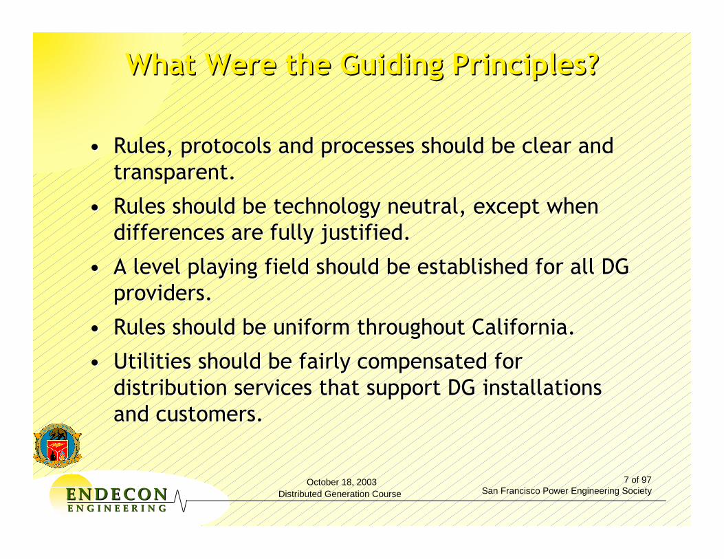
•• Rules, protocols and processes should be clear and Rules, protocols and processes should be clear and transparent.transparent.
•• Rules should be technology neutral, except when Rules should be technology neutral, except when differences are fully justified.differences are fully justified.
•• A level playing field should be established for all DG A level playing field should be established for all DG providers.providers.
•• Rules should be uniform throughout California.Rules should be uniform throughout California.
•• Utilities should be fairly compensated for Utilities should be fairly compensated for distribution services that support DG installations distribution services that support DG installations and customers. and customers.
What Were the Guiding Principles?What Were the Guiding Principles?

October 18, 2003Distributed Generation Course
8 of 97San Francisco Power Engineering SocietyEENNDDEE CCOONN
EE NN GG II NN EE EE RR II NN GG
Rule 21 Rule 21 -- HighlightsHighlights
CPUC Jurisdictional Projects OnlyCPUC Jurisdictional Projects Only
Application ProcessApplication Process
▲▲ Standard CPUC FormStandard CPUC Form
▲▲ Application Fee:Application Fee:
➤➤ $800: Initial Review Only$800: Initial Review Only
➤➤ $600 Additional: Supplemental Review$600 Additional: Supplemental Review
➤➤ Cost Estimate for IC StudyCost Estimate for IC Study
▲▲ Utilities to Complete Within 10/20 DaysUtilities to Complete Within 10/20 Days
(Initial/Supplemental Reviews Only)(Initial/Supplemental Reviews Only)

October 18, 2003Distributed Generation Course
9 of 97San Francisco Power Engineering SocietyEENNDDEE CCOONN
EE NN GG II NN EE EE RR II NN GG
•• Interconnection FeesInterconnection Fees
•• Testing and Certification Testing and Certification ProceduresProcedures
•• Clear Engineering Review ProcessClear Engineering Review Process
•• Interconnection AgreementsInterconnection Agreements
•• Application Forms (Paper and Application Forms (Paper and Electronic)Electronic)
•• Process for Continuing Process for Continuing RefinementRefinement
Issues Addressed by the Rule 21 Working Issues Addressed by the Rule 21 Working GroupGroup
October 18, 2003Distributed Generation Course
10 of 97San Francisco Power Engineering SocietyEENNDDEE CCOONN
EE NN GG II NN EE EE RR II NN GG
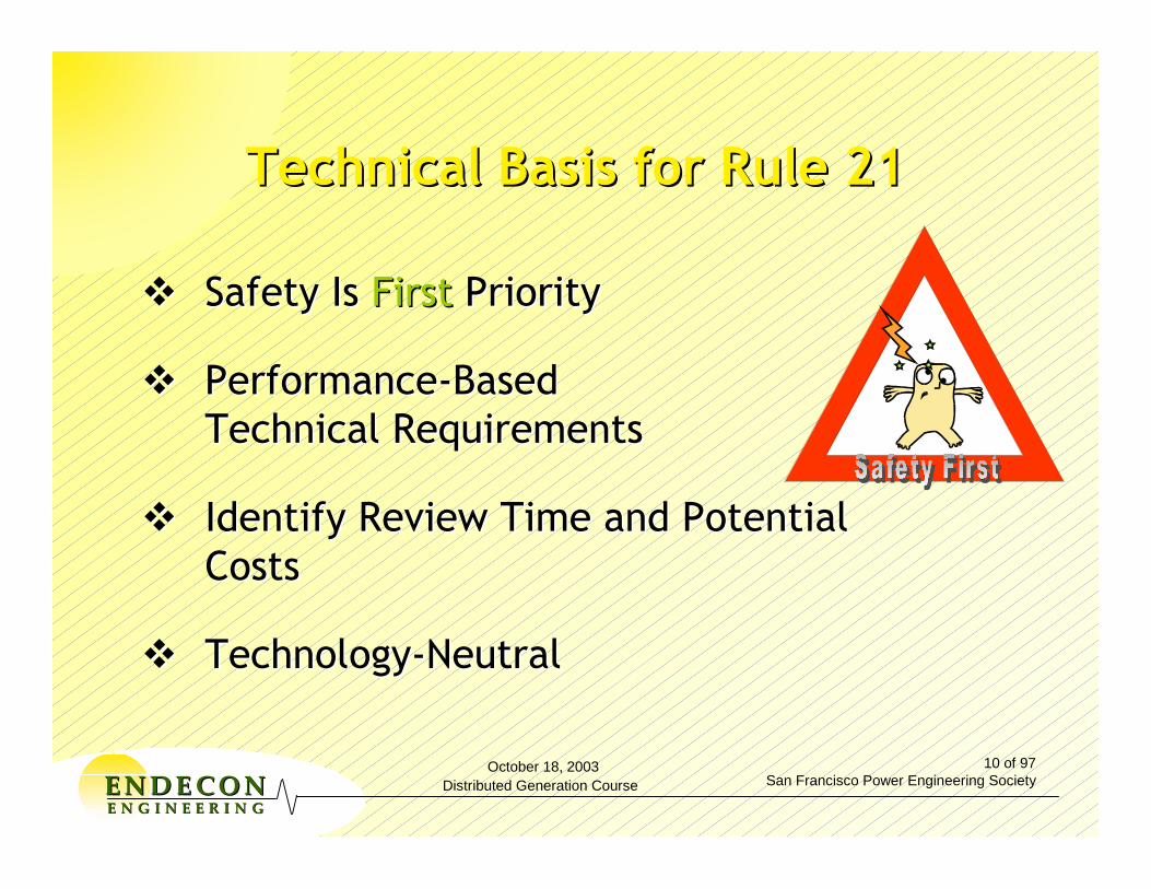
Technical Basis for Rule 21Technical Basis for Rule 21
Safety Is Safety Is FirstFirst PriorityPriority
PerformancePerformance--BasedBasedTechnical RequirementsTechnical Requirements
Identify Review Time and PotentialIdentify Review Time and PotentialCostsCosts
TechnologyTechnology--NeutralNeutral

October 18, 2003Distributed Generation Course
11 of 97San Francisco Power Engineering SocietyEENNDDEE CCOONN
EE NN GG II NN EE EE RR II NN GG
Rule 21 Technical Requirements Rule 21 Technical Requirements
Section D Section D -- Design & OperatingDesign & OperatingRequirementsRequirements
1. 1. GeneralGeneral
•• Protective FunctionsProtective Functions
•• Momentary ParallelingMomentary Paralleling
•• Equipment RequirementsEquipment Requirements
•• Visible DisconnectVisible Disconnect
•• DrawingsDrawings RequiredRequired DG Section D
October 18, 2003Distributed Generation Course
12 of 97San Francisco Power Engineering SocietyEENNDDEE CCOONN
EE NN GG II NN EE EE RR II NN GG
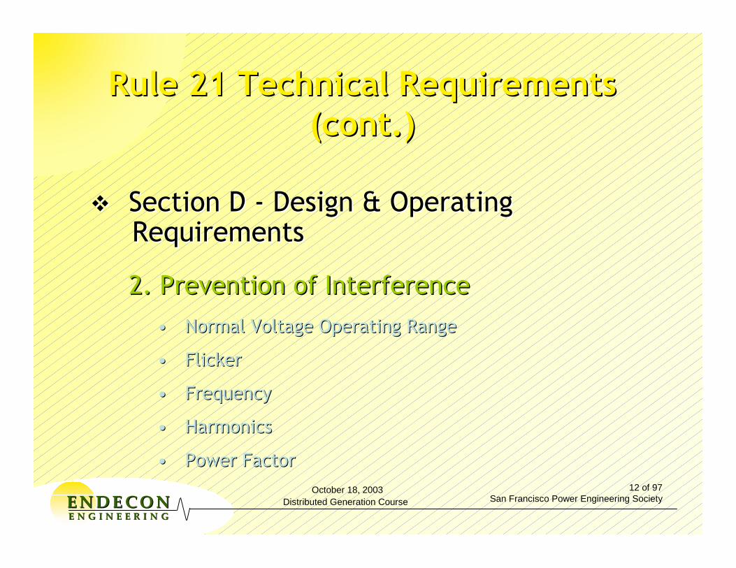
Rule 21 Technical Requirements Rule 21 Technical Requirements (cont.)(cont.)
Section D Section D -- Design & OperatingDesign & OperatingRequirementsRequirements
2. Prevention of Interference2. Prevention of Interference
•• Normal Voltage Operating RangeNormal Voltage Operating Range
•• FlickerFlicker
•• FrequencyFrequency
•• HarmonicsHarmonics
•• Power FactorPower Factor

October 18, 2003Distributed Generation Course
13 of 97San Francisco Power Engineering SocietyEENNDDEE CCOONN
EE NN GG II NN EE EE RR II NN GG
Rule 21 Technical Requirements Rule 21 Technical Requirements (cont.)(cont.)
Section D Section D -- Design & OperatingDesign & OperatingRequirementsRequirements
3. Control & Protective Functions3. Control & Protective Functions
•• Technology Specific RequirementsTechnology Specific Requirements
•• Mitigation of Unintended IslandingMitigation of Unintended Islanding
•• Fault DetectionFault Detection

October 18, 2003Distributed Generation Course
14 of 97San Francisco Power Engineering SocietyEENNDDEE CCOONN
EE NN GG II NN EE EE RR II NN GG
Rule 21 Technical Requirements Rule 21 Technical Requirements (cont.)(cont.)
Section I Section I -- Review ProcessReview Process
Determines:Determines:
•• Simplified Interconnection (via InitialSimplified Interconnection (via InitialReview)Review)
•• Supplemental Review Determines If ThereSupplemental Review Determines If ThereAre Additional Requirements forAre Additional Requirements forInterconnection or...Interconnection or...
•• If an Interconnection Study Is RequiredIf an Interconnection Study Is Required
October 18, 2003Distributed Generation Course
15 of 97San Francisco Power Engineering SocietyEENNDDEE CCOONN
EE NN GG II NN EE EE RR II NN GG
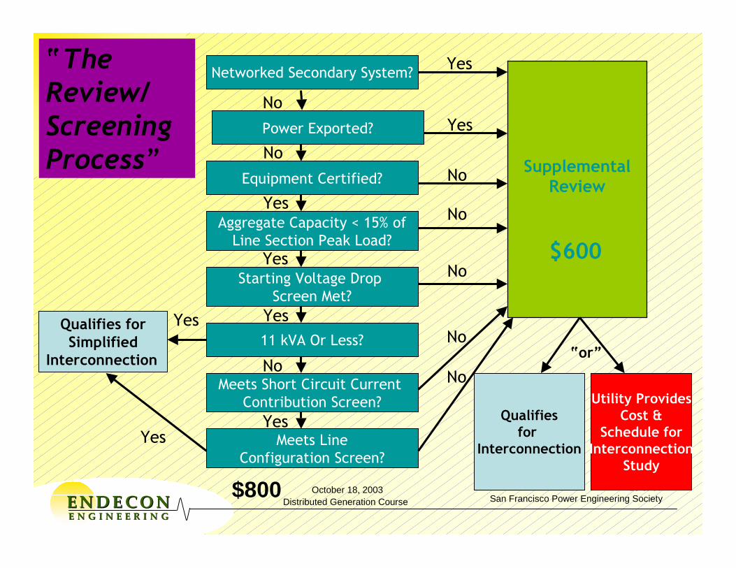
“The Review/Screening Process”
Networked Secondary System?
Equipment Certified?
Starting Voltage Drop Screen Met?
11 kVA Or Less?
Meets Short Circuit Current Contribution Screen?
Meets LineConfiguration Screen?
Qualifies for Simplified
Interconnection
Yes
No
Yes
No
Yes
Power Exported?
No
Aggregate Capacity < 15% ofLine Section Peak Load?
Yes
SupplementalReview
No
No
No
No
No
Qualifiesfor
Interconnection
Yes
Yes
Yes
Yes
Utility ProvidesCost &
Schedule forInterconnection
Study
$800
$600
“or”
October 18, 2003Distributed Generation Course
16 of 97San Francisco Power Engineering SocietyEENNDDEE CCOONN
EE NN GG II NN EE EE RR II NN GG
Rule 21 Technical Requirements Rule 21 Technical Requirements (cont.)(cont.)
Section I Section I -- Supplemental ReviewSupplemental Review
–– Guideline Developed in 2002 Through Guideline Developed in 2002 Through Rule 21 Working Group ProcessRule 21 Working Group Process
–– Goals: Identify Review Criteria and Goals: Identify Review Criteria and Study Requirements Study Requirements
–– Draft Issued in JanuaryDraft Issued in January20032003
October 18, 2003Distributed Generation Course
17 of 97San Francisco Power Engineering SocietyEENNDDEE CCOONN
EE NN GG II NN EE EE RR II NN GG
Rule 21 Technical Requirements Rule 21 Technical Requirements (cont.)(cont.)
Section J Section J -- Testing and CertificationTesting and Certification
–– Certification CriteriaCertification Criteria
–– Type TestingType Testing
•• Individual Tests Individual Tests -- By Technology TypeBy Technology Type
•• UL 1741 ReferencedUL 1741 Referenced
•• Surge Withstand TestSurge Withstand Test
CERTIFICATION

October 18, 2003Distributed Generation Course
18 of 97San Francisco Power Engineering SocietyEENNDDEE CCOONN
EE NN GG II NN EE EE RR II NN GG
Rule 21 Technical Requirements Rule 21 Technical Requirements (cont.)(cont.)
Section J Section J -- Testing/CertificationTesting/Certification
-- Production TestingProduction Testing
-- Commissioning TestingCommissioning Testing
•• General RequirementsGeneral Requirements
•• Protective Functions to Be Protective Functions to Be TestedTested
•• Impact of CertificationImpact of Certification
•• Verification of SettingsVerification of Settings
•• Trip TestTrip Test
October 18, 2003Distributed Generation Course
19 of 97San Francisco Power Engineering SocietyEENNDDEE CCOONN
EE NN GG II NN EE EE RR II NN GG
For More Information...For More Information...
Scott TomashefskyScott Tomashefsky
California Energy CommissionCalifornia Energy Commission
[email protected]@energy.state.ca.uswww.energy.ca.www.energy.ca.govgov//distgendistgen/interconnection/interconnection.html/interconnection/interconnection.html
October 18, 2003Distributed Generation Course
20 of 97San Francisco Power Engineering SocietyEENNDDEE CCOONN
EE NN GG II NN EE EE RR II NN GG
Other State RequirementsOther State Requirements
•• NY SIR NY SIR http://www.dps.state.ny.us/distgen.htmhttp://www.dps.state.ny.us/distgen.htm
•• Texas: Texas: http://www.puc.state.tx.us/electric/projects/21965/21965.cfmhttp://www.puc.state.tx.us/electric/projects/21965/21965.cfmhttp://www.puc.state.tx.us/rules/subrules/electric/25.211/25.211http://www.puc.state.tx.us/rules/subrules/electric/25.211/25.211ei.cfmei.cfm
•• Good resource: Good resource: www.irecusa.orgwww.irecusa.org–– Sign up for Steve Sign up for Steve Kalland’sKalland’s newsletter newsletter
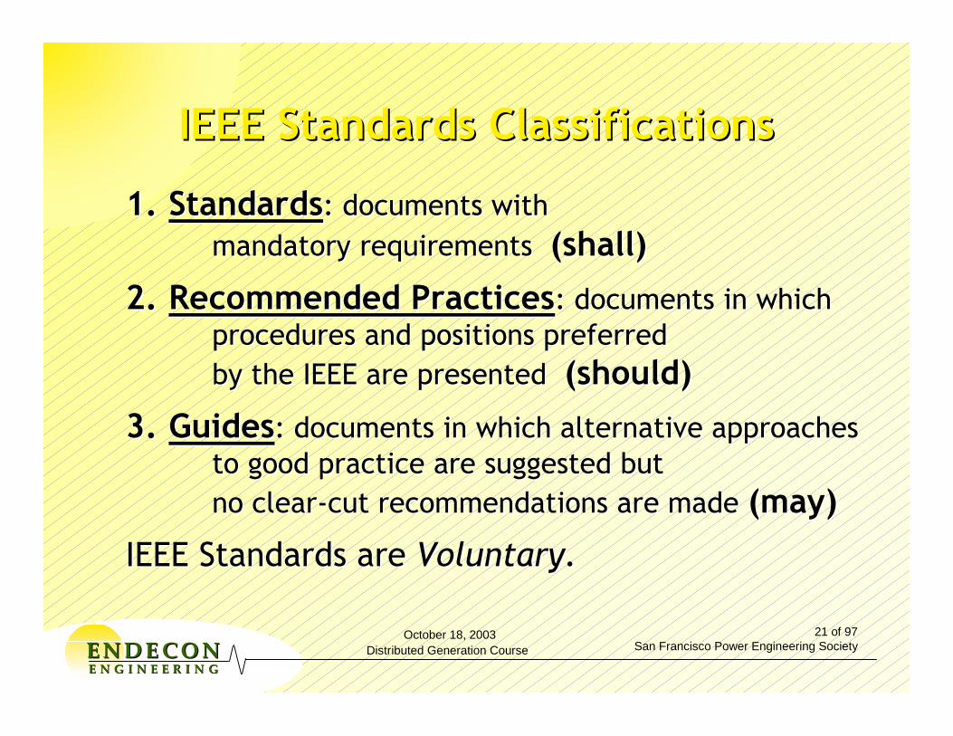
October 18, 2003Distributed Generation Course
21 of 97San Francisco Power Engineering SocietyEENNDDEE CCOONN
EE NN GG II NN EE EE RR II NN GG
1.1. StandardsStandards: documents with : documents with mandatory requirements mandatory requirements (shall)(shall)
2.2. Recommended PracticesRecommended Practices: documents in which : documents in which procedures and positions preferred procedures and positions preferred by the IEEE are presented by the IEEE are presented (should)(should)
3.3. GuidesGuides: documents in which alternative approaches: documents in which alternative approachesto good practice are suggested but to good practice are suggested but no clearno clear--cut recommendations are made cut recommendations are made (may)(may)
IEEE Standards areIEEE Standards are Voluntary.Voluntary.
IEEE Standards ClassificationsIEEE Standards Classifications
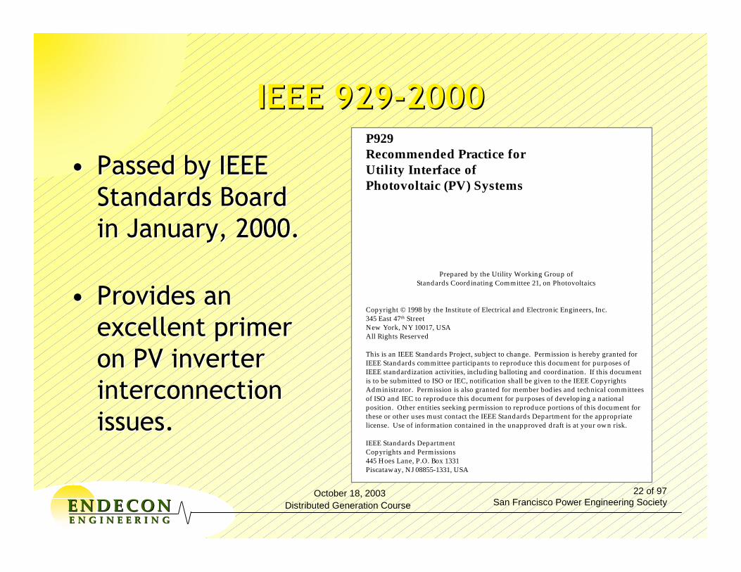
October 18, 2003Distributed Generation Course
22 of 97San Francisco Power Engineering SocietyEENNDDEE CCOONN
EE NN GG II NN EE EE RR II NN GG
P929Recommended Practice forUtility Interface ofPhotovoltaic (PV) Systems
Prepared by the Utility Working Group ofStandards Coordinating Committee 21, on Photovoltaics
Copyright © 1998 by the Institute of Electrical and Electronic Engineers, Inc.345 East 47th StreetNew York, NY 10017, USAAll Rights Reserved
This is an IEEE Standards Project, subject to change. Permission is hereby granted forIEEE Standards committee participants to reproduce this document for purposes ofIEEE standardization activities, including balloting and coordination. If this documentis to be submitted to ISO or IEC, notification shall be given to the IEEE CopyrightsAdministrator. Permission is also granted for member bodies and technical committeesof ISO and IEC to reproduce this document for purposes of developing a nationalposition. Other entities seeking permission to reproduce portions of this document forthese or other uses must contact the IEEE Standards Department for the appropriatelicense. Use of information contained in the unapproved draft is at your own risk.
IEEE Standards DepartmentCopyrights and Permissions445 Hoes Lane, P.O. Box 1331Piscataway, NJ 08855-1331, USA
IEEE 929IEEE 929--20002000
•• Passed by IEEE Passed by IEEE Standards Board Standards Board in January, 2000.in January, 2000.
•• Provides an Provides an excellent primer excellent primer on PV inverter on PV inverter interconnection interconnection issues.issues.
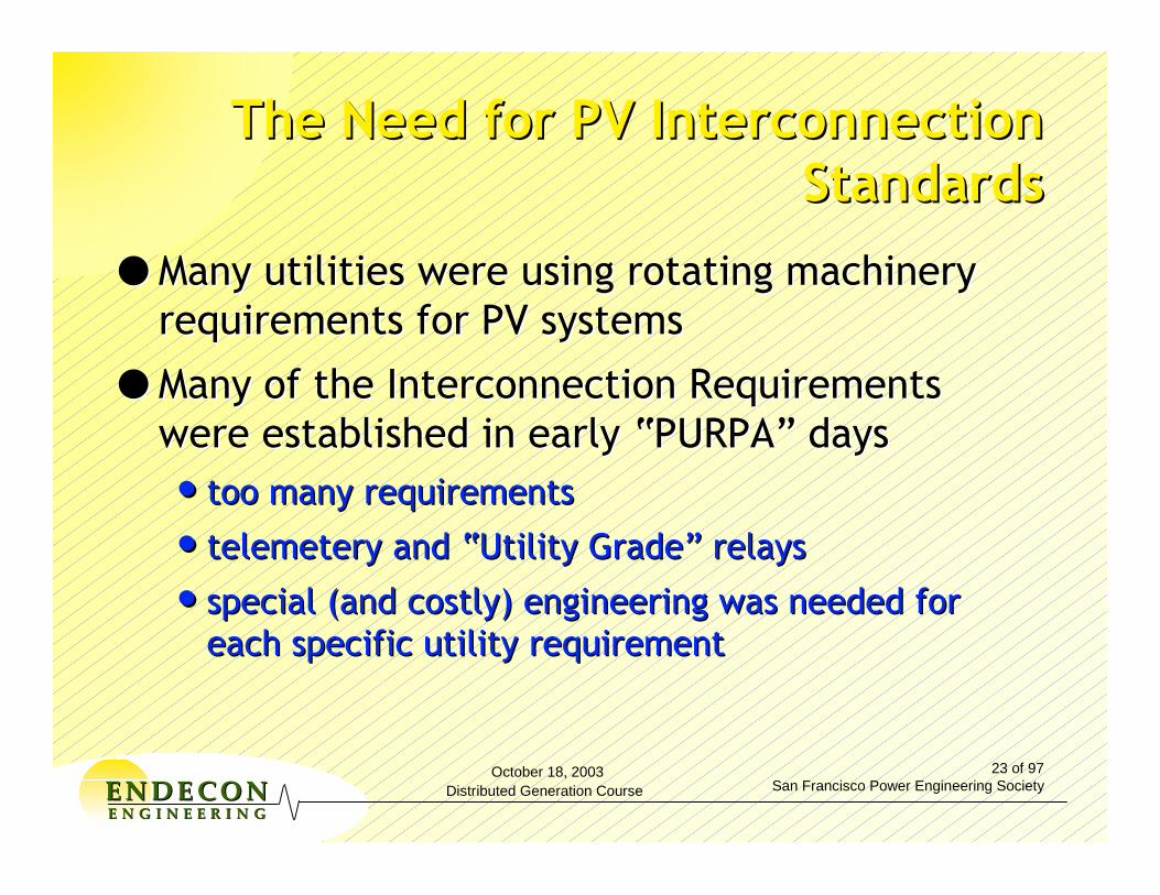
October 18, 2003Distributed Generation Course
23 of 97San Francisco Power Engineering SocietyEENNDDEE CCOONN
EE NN GG II NN EE EE RR II NN GG
The Need for PV Interconnection The Need for PV Interconnection StandardsStandards
●● Many utilities were using rotating machinery Many utilities were using rotating machinery requirements for PV systemsrequirements for PV systems
●● Many of the Interconnection Requirements Many of the Interconnection Requirements were established in early were established in early ““PURPAPURPA”” daysdays•• too many requirementstoo many requirements
•• telemeterytelemetery and and ““Utility GradeUtility Grade”” relaysrelays
•• special (and costly) engineering was needed for special (and costly) engineering was needed for each specific utility requirementeach specific utility requirement

October 18, 2003Distributed Generation Course
24 of 97San Francisco Power Engineering SocietyEENNDDEE CCOONN
EE NN GG II NN EE EE RR II NN GG
Purpose of IEEE 929Purpose of IEEE 929
““This recommended practice contains guidance This recommended practice contains guidance regarding equipment and functions necessary to regarding equipment and functions necessary to ensure compatible operation of photovoltaic ensure compatible operation of photovoltaic systems which are connected in parallel with systems which are connected in parallel with the electric utility. This includes factors the electric utility. This includes factors relating to relating to personnel safetypersonnel safety, , equipment equipment protectionprotection, , power qualitypower quality and and utility system utility system operationoperation..””
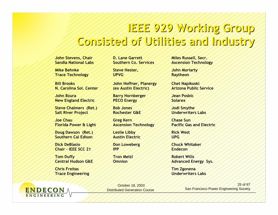
October 18, 2003Distributed Generation Course
25 of 97San Francisco Power Engineering SocietyEENNDDEE CCOONN
EE NN GG II NN EE EE RR II NN GG
IEEE 929 Working Group IEEE 929 Working Group Consisted of Utilities and IndustryConsisted of Utilities and Industry
John Stevens, ChairSandia National Labs
D. Lane GarrettSouthern Co. Services
Miles Russell, Secr.Ascension Technology
Mike Behnke Trace Technology
Steve Hester, UPVG
John Moriarty Raytheon
Bill Brooks N. Carolina Sol. Center
John Hoffner, Planergy (ex Austin Electric)
Chet Napikoski Arizona Public Service
John Bzura New England Electric
Barry Hornberger PECO Energy
Jean Posbic Solarex
Steve Chalmers (Ret.) Salt River Project
Bob Jones Rochester G&E
Jodi Smythe Underwriters Labs
Joe Chau Florida Power & Light
Greg Kern Ascension Technology
Chase Sun Pacific Gas and Electric
Doug Dawson (Ret.) Southern Cal Edison
Leslie Libby Austin Electric
Rick West UPG
Dick DeBlasio Chair – IEEE SCC 21
Don Loweberg IPP
Chuck Whitaker Endecon
Tom Duffy Central Hudson G&E
Tron Melzl Omnion
Robert Wills Advanced Energy Sys.
Chris Freitas Trace Engineering
Tim Zgonena Underwriters Labs

October 18, 2003Distributed Generation Course
26 of 97San Francisco Power Engineering SocietyEENNDDEE CCOONN
EE NN GG II NN EE EE RR II NN GG
What Does IEEE 929 Really Impact?What Does IEEE 929 Really Impact?
PV ArrayInverterMUtilitySystem

October 18, 2003Distributed Generation Course
27 of 97San Francisco Power Engineering SocietyEENNDDEE CCOONN
EE NN GG II NN EE EE RR II NN GG
IEEE 929 OutlineIEEE 929 Outline
•• IntroductionIntroduction
•• 1. Overview (scope & purpose)1. Overview (scope & purpose)
•• 2. References2. References
•• 3. Definitions (inverter, islanding, PCC, 3. Definitions (inverter, islanding, PCC, quality factor, etc.)quality factor, etc.)
•• 4. Power quality4. Power quality
•• 5. Safety and protection functions5. Safety and protection functions
•• AnnexesAnnexes

October 18, 2003Distributed Generation Course
28 of 97San Francisco Power Engineering SocietyEENNDDEE CCOONN
EE NN GG II NN EE EE RR II NN GG
IEEE 929IEEE 929--2000 2000 Power QualityPower Quality
•• Power quality problems in general are rising Power quality problems in general are rising because of proliferation of nonbecause of proliferation of non--linear loads on linear loads on utility systems utility systems ---- all customers sufferall customers suffer
•• PV should not add to that problemPV should not add to that problem
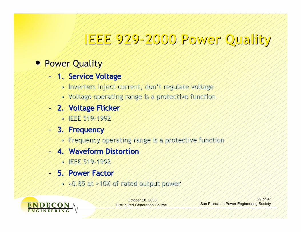
October 18, 2003Distributed Generation Course
29 of 97San Francisco Power Engineering SocietyEENNDDEE CCOONN
EE NN GG II NN EE EE RR II NN GG
IEEE 929IEEE 929--2000 Power Quality2000 Power Quality
•• Power QualityPower Quality–– 1. Service Voltage1. Service Voltage
•• Inverters inject current, donInverters inject current, don’’t regulate voltaget regulate voltage•• Voltage operating range is a protective functionVoltage operating range is a protective function
–– 2. Voltage Flicker2. Voltage Flicker•• IEEE 519IEEE 519--19921992
–– 3. Frequency3. Frequency•• Frequency operating range is a protective functionFrequency operating range is a protective function
–– 4. Waveform Distortion4. Waveform Distortion•• IEEE 519IEEE 519--19921992
–– 5. Power Factor5. Power Factor•• >0.85 at >10% of rated output power>0.85 at >10% of rated output power

October 18, 2003Distributed Generation Course
30 of 97San Francisco Power Engineering SocietyEENNDDEE CCOONN
EE NN GG II NN EE EE RR II NN GG
IEEE 929IEEE 929--2000 2000 Safety and Protection FunctionsSafety and Protection Functions
•• Response to Abnormal Utility ConditionsResponse to Abnormal Utility Conditions–– Voltage DisturbancesVoltage Disturbances–– Frequency DisturbancesFrequency Disturbances–– Islanding ProtectionIslanding Protection
•• Annex A AntiAnnex A Anti--Islanding TestIslanding Test
–– Reconnect After a Utility DisturbanceReconnect After a Utility Disturbance•• 5 min delay5 min delay
•• Direct Current IsolationDirect Current Isolation–– <0.5% of rated output current<0.5% of rated output current
•• GroundingGrounding–– Meet local codesMeet local codes
•• Manual DisconnectManual Disconnect–– Not required for nonNot required for non--islanding invertersislanding inverters

October 18, 2003Distributed Generation Course
31 of 97San Francisco Power Engineering SocietyEENNDDEE CCOONN
EE NN GG II NN EE EE RR II NN GG
IEEE 929IEEE 929--2000 Response to 2000 Response to Abnormal Utility ConditionsAbnormal Utility Conditions
Voltage (at PCC) Maximum Trip Time* V< 60 (V<50%) 6 cycles 60≤V<106 (50%≤V<88%) 120 cycles
106≤V≤132 (88%≤V≤110%) Normal Operation 132<V<165 (110%<V<137%) 120 cycles
165≤V (137%≤V) 2 cycles Frequency (at PCC) Maximum Trip Time*
<59.3 Hz 6 cycles 59.3 - 60.5 Hz (normal) --
>60.5 Hz 6 cycles
*”Trip time” refers to the time between the abnormal condition being applied and the inverter ceasing to energize the utility line. The inverter will actually remain connected to the utility to allow sensing of utility electrical conditions for use by the “reconnect” feature.

October 18, 2003Distributed Generation Course
32 of 97San Francisco Power Engineering SocietyEENNDDEE CCOONN
EE NN GG II NN EE EE RR II NN GG
IEEE 929IEEE 929--2000 2000 Manual Disconnect SwitchManual Disconnect Switch
PV Array
InverterM
LocalLoads
UtilitySystem

October 18, 2003Distributed Generation Course
33 of 97San Francisco Power Engineering SocietyEENNDDEE CCOONN
EE NN GG II NN EE EE RR II NN GG
IEEE 929IEEE 929--2000 2000 -- AnnexesAnnexes
•• Annex Annex A (Normative)A (Normative) –– Minimum Test Procedure for Minimum Test Procedure for a Nona Non--Islanding PV InverterIslanding PV Inverter
•• Annex Annex B (Informative)B (Informative) -- BibliographyBibliography•• Annex Annex CC -- PV Inverters and the Utility InterfacePV Inverters and the Utility Interface
(Terminology)(Terminology)•• Annex Annex DD -- Disconnect Switches & Utility ProceduresDisconnect Switches & Utility Procedures•• Annex Annex EE -- Islanding as it Applies to PV SystemsIslanding as it Applies to PV Systems•• Annex Annex FF -- The PV Inverter Under Utility Fault The PV Inverter Under Utility Fault
ConditionsConditions•• Annex Annex GG -- Dedicated Distribution TransformerDedicated Distribution Transformer

October 18, 2003Distributed Generation Course
34 of 97San Francisco Power Engineering SocietyEENNDDEE CCOONN
EE NN GG II NN EE EE RR II NN GG
IEEE 1547IEEE 1547--20032003
Standard for Interconnecting Standard for Interconnecting Distributed Resources with Electric Distributed Resources with Electric
Power Systems Power Systems
(Thanks to Richard DeBlasio and Tom Basso)(Thanks to Richard DeBlasio and Tom Basso)

October 18, 2003Distributed Generation Course
35 of 97San Francisco Power Engineering SocietyEENNDDEE CCOONN
EE NN GG II NN EE EE RR II NN GG
1547 Standard for Interconnecting Distributed Resources with Electric Power Systems
P1547.1Draft Standard for Conformance Test Procedures for Equipment Interconnecting Distributed Resources with Electric Power Systems
P1547.2Draft Application Guide for IEEE P1547 Draft Standard for Interconnecting Distributed Resources with Electric Power Systems
Guide for Networks Guide for Impacts
Guide for Islanding & Anti-Islanding
DR Specifications and Performance
Guide For
Interconnection System
Certification
P1547.3Draft Guide for Monitoring, Information Exchange and Control of DR Interconnected with EPS
IEEE 1547 Body of StandardsIEEE 1547 Body of Standards

October 18, 2003Distributed Generation Course
36 of 97San Francisco Power Engineering SocietyEENNDDEE CCOONN
EE NN GG II NN EE EE RR II NN GG
Round 1Round 1---- Draft 7Draft 7•• Balloting completed 4/1/01Balloting completed 4/1/01•• 91% ballot returns91% ballot returns•• 66% affirmative66% affirmative•• Addressed negative commentsAddressed negative comments
Voter Category Affirm Negative Voter Category Affirm Negative -- User User 30 2330 23-- Producer Producer 35 12 35 12 -- General Interest 28 15General Interest 28 15
Requirements for adoption: 75% ballot return, 75% affirmativeRequirements for adoption: 75% ballot return, 75% affirmative
Round 2 Round 2 ---- Draft 8Draft 8•• Recirculation completed 10/2/01Recirculation completed 10/2/01•• 96% ballot returns96% ballot returns•• 66% affirmative66% affirmative•• New Draft TBDNew Draft TBD
Voter Category Affirm Negative Voter Category Affirm Negative -- User User 25 3325 33-- Producer Producer 43 6 43 6 -- General Interest 35 14General Interest 35 14
IEEE P1547 IEEE P1547 Drafts 7 and 8 Ballot StatusDrafts 7 and 8 Ballot Status

October 18, 2003Distributed Generation Course
37 of 97San Francisco Power Engineering SocietyEENNDDEE CCOONN
EE NN GG II NN EE EE RR II NN GG
Requirements for adoption: 75% ballot returns, 75% affirmativRequirements for adoption: 75% ballot returns, 75% affirmatives es
Ballot ResultsBallot Results•• Ballot Action August 28 Ballot Action August 28 -- September 26, 2002 September 26, 2002 •• 93% ballot returns (230 in ballot group) 93% ballot returns (230 in ballot group) •• 90% affirmatives 90% affirmatives •• 10% negatives 10% negatives •• 3% abstentions 3% abstentions
Voter Category Affirmatives Negatives Voter Category Affirmatives Negatives -- UserUser 63 63 99-- ProducerProducer 57 57 4 4 -- General InterestGeneral Interest 59 59 6 6 -- GovernmentGovernment 88 1 1
Voting Tally Voting Tally 187187 20 20
IEEE P1547 Draft 10 Ballot StatusIEEE P1547 Draft 10 Ballot Status

October 18, 2003Distributed Generation Course
38 of 97San Francisco Power Engineering SocietyEENNDDEE CCOONN
EE NN GG II NN EE EE RR II NN GG
Requirements for adoption: 75% ballot returns, 75% affirmativeRequirements for adoption: 75% ballot returns, 75% affirmatives s •• June 2003: IEEE Standards Board Meeting June 2003: IEEE Standards Board Meeting
Ballot ResultsBallot Results•• Ballot Action February 7 Ballot Action February 7 -- 28, 2003 28, 2003 •• 95% ballot returns (230 in ballot group) 95% ballot returns (230 in ballot group) •• 89% affirmatives 89% affirmatives •• 9% negatives 9% negatives •• 2% abstentions 2% abstentions
IEEE P1547 Draft 11 Ballot StatusIEEE P1547 Draft 11 Ballot Status
APPROVED
APPROVED

October 18, 2003Distributed Generation Course
39 of 97San Francisco Power Engineering SocietyEENNDDEE CCOONN
EE NN GG II NN EE EE RR II NN GG
1547: Interconnection Is The Focus 1547: Interconnection Is The Focus
Distributed Resource
(DR) unit
Area Electric Power
System (EPS)
Interconnection
System

October 18, 2003Distributed Generation Course
40 of 97San Francisco Power Engineering SocietyEENNDDEE CCOONN
EE NN GG II NN EE EE RR II NN GG
Local EPS 1
Area Electric Power System (EPS)
Local EPS 3
PCC
Point of DR Connection
DR unit
Local EPS 2
Point of DR Connection
Point of Common Coupling (PCC)
Note: There can be any number of Local EPSs.
PCC
DR unit Load Load
1547 Interconnection Terms 1547 Interconnection Terms

October 18, 2003Distributed Generation Course
41 of 97San Francisco Power Engineering SocietyEENNDDEE CCOONN
EE NN GG II NN EE EE RR II NN GG
INTRODUCTION INTRODUCTION
1.01.0 OVERVIEW OVERVIEW 1.1 1.1 Scope Scope 1.2 1.2 Purpose Purpose 1.3 1.3 Limitations Limitations
2.02.0 REFERENCES REFERENCES
3.03.0 DEFINITIONSDEFINITIONS
IEEE 1547IEEE 1547--2003 2003 ContentsContents
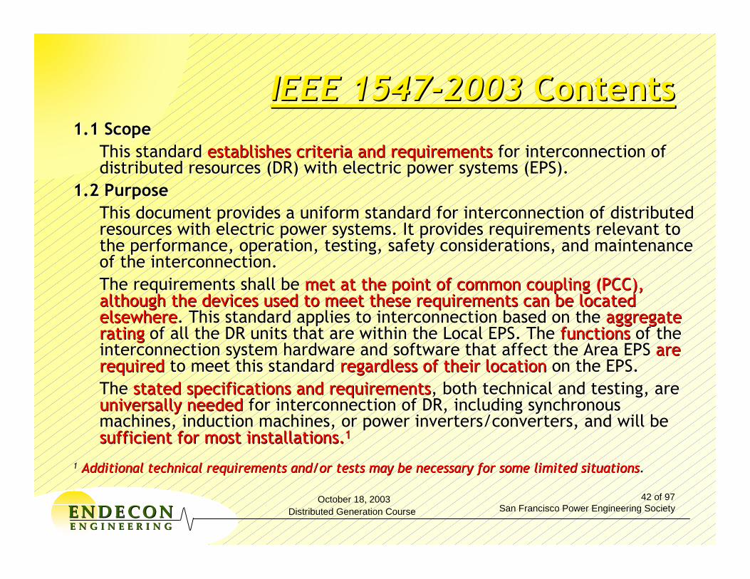
October 18, 2003Distributed Generation Course
42 of 97San Francisco Power Engineering SocietyEENNDDEE CCOONN
EE NN GG II NN EE EE RR II NN GG
IEEE 1547IEEE 1547--2003 2003 ContentsContents1.1 Scope1.1 Scope
This standard This standard establishes criteria and requirementsestablishes criteria and requirements for interconnection of for interconnection of distributed resources (DR) with electric power systems (EPS).distributed resources (DR) with electric power systems (EPS).
1.2 Purpose1.2 PurposeThis document provides a uniform standard for interconnection ofThis document provides a uniform standard for interconnection of distributed distributed resources with electric power systems. It provides requirements resources with electric power systems. It provides requirements relevant to relevant to the performance, operation, testing, safety considerations, and the performance, operation, testing, safety considerations, and maintenance maintenance of the interconnection.of the interconnection.The requirements shall be The requirements shall be met at the point of common coupling (PCC), met at the point of common coupling (PCC), although the devices used to meet these requirements can be locaalthough the devices used to meet these requirements can be located ted elsewhereelsewhere. This standard applies to interconnection based on the . This standard applies to interconnection based on the aggregate aggregate ratingrating of all the DR units that are within the Local EPS. The of all the DR units that are within the Local EPS. The functionsfunctions of the of the interconnection system hardware and software that affect the Areinterconnection system hardware and software that affect the Area EPS a EPS are are requiredrequired to meet this standard to meet this standard regardless of their locationregardless of their location on the EPS.on the EPS.The The stated specifications and requirementsstated specifications and requirements, both technical and testing, are , both technical and testing, are universally neededuniversally needed for interconnection of DR, including synchronous for interconnection of DR, including synchronous machines, induction machines, or power inverters/converters, andmachines, induction machines, or power inverters/converters, and will be will be sufficient for most installations.sufficient for most installations.11
11 Additional technical requirements and/or tests may be necessary Additional technical requirements and/or tests may be necessary for some limited situationsfor some limited situations..

October 18, 2003Distributed Generation Course
43 of 97San Francisco Power Engineering SocietyEENNDDEE CCOONN
EE NN GG II NN EE EE RR II NN GG
4.04.0 INTERCONNECTION TECHNICAL SPECIFICATIONS AND INTERCONNECTION TECHNICAL SPECIFICATIONS AND REQUIREMENTSREQUIREMENTS
4.1 General Requirements 4.1 General Requirements 4.2 Response to Area EPS Abnormal Conditions4.2 Response to Area EPS Abnormal Conditions4.3 Power Quality 4.3 Power Quality 4.4 Islanding 4.4 Islanding
5.0 INTERCONNECTION TEST SPECIFICATIONS AND 5.0 INTERCONNECTION TEST SPECIFICATIONS AND REQUIREMENTS REQUIREMENTS
5.15.1 Design Test Design Test 5.25.2 Production Tests Production Tests 5.35.3 Interconnection Installation Evaluation Interconnection Installation Evaluation 5.45.4 Commissioning Tests Commissioning Tests 5.55.5 Periodic Interconnection Tests Periodic Interconnection Tests
ANNEX A (INFORMATIVE) BIBLIOGRAPHYANNEX A (INFORMATIVE) BIBLIOGRAPHY
IEEE 1547IEEE 1547--20032003 ContentsContents
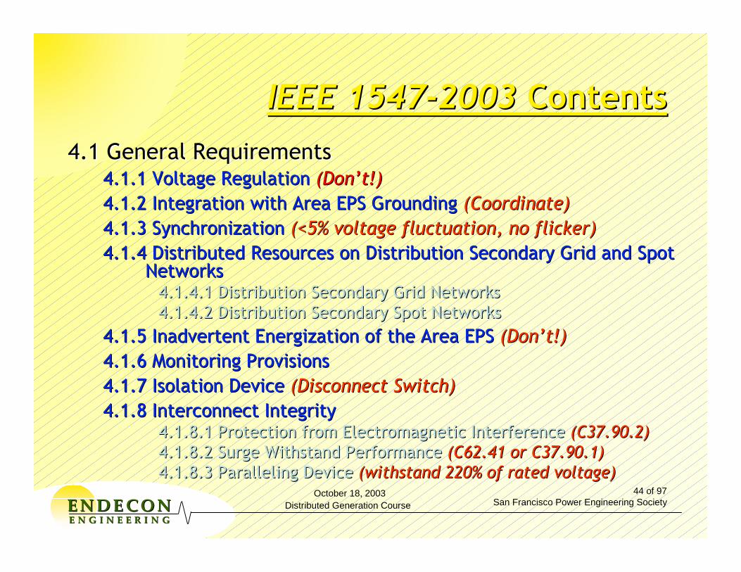
October 18, 2003Distributed Generation Course
44 of 97San Francisco Power Engineering SocietyEENNDDEE CCOONN
EE NN GG II NN EE EE RR II NN GG
IEEE 1547IEEE 1547--20032003 ContentsContents4.1 General Requirements4.1 General Requirements
4.1.1 Voltage Regulation4.1.1 Voltage Regulation (Don’t!)(Don’t!)4.1.2 Integration with Area EPS Grounding 4.1.2 Integration with Area EPS Grounding (Coordinate)(Coordinate)4.1.3 Synchronization 4.1.3 Synchronization (<5% voltage fluctuation, no flicker)(<5% voltage fluctuation, no flicker)4.1.4 Distributed Resources on Distribution Secondary Grid and S4.1.4 Distributed Resources on Distribution Secondary Grid and Spot pot
NetworksNetworks4.1.4.1 Distribution Secondary Grid Networks4.1.4.1 Distribution Secondary Grid Networks4.1.4.2 Distribution Secondary Spot Networks4.1.4.2 Distribution Secondary Spot Networks
4.1.5 Inadvertent Energization of the Area EPS 4.1.5 Inadvertent Energization of the Area EPS (Don’t!)(Don’t!)4.1.6 Monitoring Provisions4.1.6 Monitoring Provisions4.1.7 Isolation Device4.1.7 Isolation Device (Disconnect Switch)(Disconnect Switch)4.1.8 Interconnect Integrity4.1.8 Interconnect Integrity
4.1.8.1 Protection from Electromagnetic Interference 4.1.8.1 Protection from Electromagnetic Interference (C37.90.2)(C37.90.2)4.1.8.2 Surge Withstand Performance 4.1.8.2 Surge Withstand Performance (C62.41 or C37.90.1)(C62.41 or C37.90.1)4.1.8.3 Paralleling Device 4.1.8.3 Paralleling Device (withstand 220% of rated voltage)(withstand 220% of rated voltage)

October 18, 2003Distributed Generation Course
45 of 97San Francisco Power Engineering SocietyEENNDDEE CCOONN
EE NN GG II NN EE EE RR II NN GG
IEEE 1547IEEE 1547--20032003 ContentsContents4.2 Response to Area EPS Abnormal Conditions4.2 Response to Area EPS Abnormal Conditions
4.2.1 Area EPS Faults 4.2.1 Area EPS Faults (detect faults, cease to energize)(detect faults, cease to energize)4.2.2 Area EPS Reclosing Coordination4.2.2 Area EPS Reclosing Coordination (coordinate)(coordinate)4.2.3 Voltage 4.2.3 Voltage (<60V,106V (<60V,106V –– 132V, >144V)132V, >144V)4.2.4 Frequency 4.2.4 Frequency (59.3 (59.3 –– 60.5 Hz)60.5 Hz)4.2.5 Loss of Synchronism 4.2.5 Loss of Synchronism (not required unless there is flicker)(not required unless there is flicker)4.2.6 Reconnection To Area EPS 4.2.6 Reconnection To Area EPS (up to 5 min, C84.1 Range B)(up to 5 min, C84.1 Range B)
4.3 Power Quality4.3 Power Quality4.3.1 Limitation of DC Injection 4.3.1 Limitation of DC Injection (>0.5% of rated output current)(>0.5% of rated output current)4.3.2 Limitation of Flicker Induced by the DR 4.3.2 Limitation of Flicker Induced by the DR (Don’t)(Don’t)4.3.3 Harmonics 4.3.3 Harmonics (~IEEE 519)(~IEEE 519)
4.4 Islanding4.4 Islanding4.4.1 Unintentional Islanding 4.4.1 Unintentional Islanding (Don’t)(Don’t)4.4.2 Intentional Islanding 4.4.2 Intentional Islanding (Don’t know)(Don’t know)

October 18, 2003Distributed Generation Course
46 of 97San Francisco Power Engineering SocietyEENNDDEE CCOONN
EE NN GG II NN EE EE RR II NN GG
IEEE 1547IEEE 1547--20032003 ContentsContents
55..0 INTERCONNECTION TEST SPECIFICATIONS AND 0 INTERCONNECTION TEST SPECIFICATIONS AND REQUIREMENTSREQUIREMENTS
5.1 Design Test5.1 Design Test5.1.1 Response to Abnormal Voltage and Frequency5.1.1 Response to Abnormal Voltage and Frequency5.1.2 Synchronization5.1.2 Synchronization5.1.3 Interconnect Integrity Test5.1.3 Interconnect Integrity Test5.1.3.1 Protection From Electromagnetic Interference (EMI)5.1.3.1 Protection From Electromagnetic Interference (EMI)
5.1.3.2 Surge Withstand Performance5.1.3.2 Surge Withstand Performance5.1.3.3 Paralleling Device5.1.3.3 Paralleling Device
5.1.4 Unintentional Islanding 5.1.4 Unintentional Islanding 5.1.5 Limitation of DC Injection5.1.5 Limitation of DC Injection5.1.6 Harmonics5.1.6 Harmonics
5.2 Production Tests5.2 Production Tests
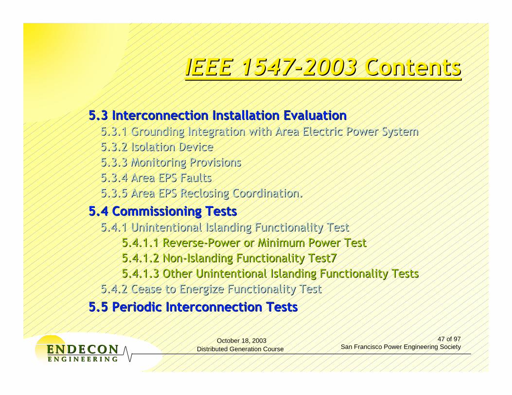
October 18, 2003Distributed Generation Course
47 of 97San Francisco Power Engineering SocietyEENNDDEE CCOONN
EE NN GG II NN EE EE RR II NN GG
IEEE 1547IEEE 1547--20032003 ContentsContents
5.3 Interconnection Installation Evaluation5.3 Interconnection Installation Evaluation5.3.1 Grounding Integration with Area Electric Power System5.3.1 Grounding Integration with Area Electric Power System5.3.2 Isolation Device5.3.2 Isolation Device5.3.3 Monitoring Provisions5.3.3 Monitoring Provisions5.3.4 Area EPS Faults5.3.4 Area EPS Faults5.3.5 Area EPS Reclosing Coordination.5.3.5 Area EPS Reclosing Coordination.
5.4 Commissioning Tests5.4 Commissioning Tests5.4.1 Unintentional Islanding Functionality Test5.4.1 Unintentional Islanding Functionality Test
5.4.1.1 Reverse5.4.1.1 Reverse--Power or Minimum Power TestPower or Minimum Power Test5.4.1.2 Non5.4.1.2 Non--Islanding Functionality Test7Islanding Functionality Test75.4.1.3 Other Unintentional Islanding Functionality Tests5.4.1.3 Other Unintentional Islanding Functionality Tests
5.4.2 Cease to Energize Functionality Test5.4.2 Cease to Energize Functionality Test
5.5 Periodic Interconnection Tests5.5 Periodic Interconnection Tests

October 18, 2003Distributed Generation Course
48 of 97San Francisco Power Engineering SocietyEENNDDEE CCOONN
EE NN GG II NN EE EE RR II NN GG
IEEE P1547.1IEEE P1547.1
• Verifies Conformance to IEEE 1547-2003
• Provides Test Procedures and order, but does not define a comprehensive Certification Process
Draft Standard for Conformance Test Procedures Draft Standard for Conformance Test Procedures for Equipment Interconnecting Distributed for Equipment Interconnecting Distributed Resources with Electric Power Systems Resources with Electric Power Systems
October 18, 2003Distributed Generation Course
49 of 97San Francisco Power Engineering SocietyEENNDDEE CCOONN
EE NN GG II NN EE EE RR II NN GG
IEEE P1547.1IEEE P1547.1
Scope:Scope:
This standard specifies the type, production, and commissioning tests that shall be performed to demonstrate that the interconnection functions and equipment of a distributed resource (DR) conform to IEEE Standard P1547.
Draft Standard for Conformance Test Procedures Draft Standard for Conformance Test Procedures for Equipment Interconnecting Distributed for Equipment Interconnecting Distributed Resources with Electric Power SystemsResources with Electric Power Systems

October 18, 2003Distributed Generation Course
50 of 97San Francisco Power Engineering SocietyEENNDDEE CCOONN
EE NN GG II NN EE EE RR II NN GG
IEEE P1547.1IEEE P1547.1
Purpose:Interconnection equipment that connects Interconnection equipment that connects distributed resources (DR) to an electric power distributed resources (DR) to an electric power system (EPS) must meet the requirements system (EPS) must meet the requirements specified in IEEE Standard P1547. Standardized specified in IEEE Standard P1547. Standardized test procedures are necessary to test procedures are necessary to establish and establish and verify complianceverify compliance with those requirements. These with those requirements. These test procedures must provide both test procedures must provide both repeatable repeatable resultsresults, independent of test location, and , independent of test location, and flexibilityflexibility to accommodate a variety of DR to accommodate a variety of DR technologies.technologies.
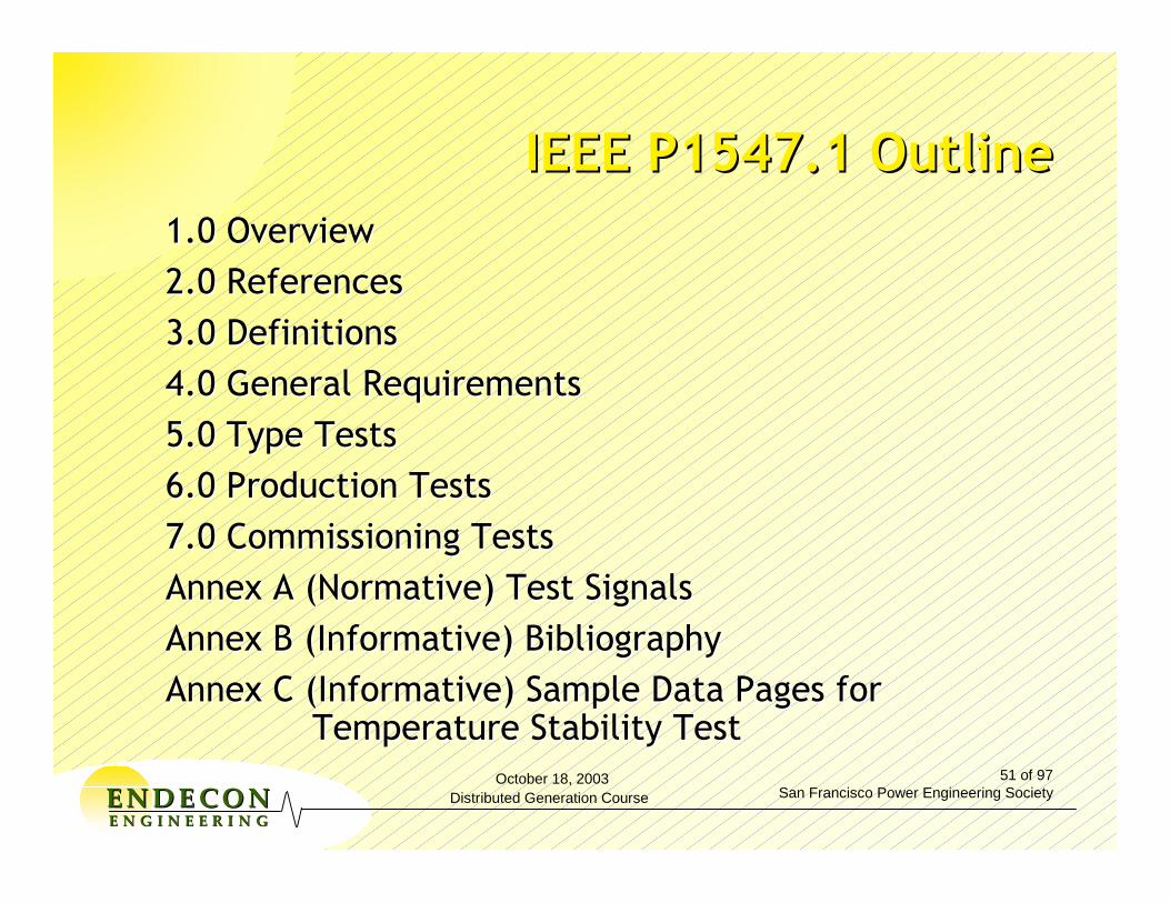
October 18, 2003Distributed Generation Course
51 of 97San Francisco Power Engineering SocietyEENNDDEE CCOONN
EE NN GG II NN EE EE RR II NN GG
IEEE P1547.1 OutlineIEEE P1547.1 Outline1.0 Overview1.0 Overview2.0 References2.0 References3.0 Definitions3.0 Definitions4.0 General Requirements4.0 General Requirements5.0 Type Tests5.0 Type Tests6.0 Production Tests6.0 Production Tests7.0 Commissioning Tests7.0 Commissioning TestsAnnex A (Normative) Test SignalsAnnex A (Normative) Test SignalsAnnex B (Informative) BibliographyAnnex B (Informative) BibliographyAnnex C (Informative) Sample Data Pages for Annex C (Informative) Sample Data Pages for
Temperature Stability TestTemperature Stability Test

October 18, 2003Distributed Generation Course
52 of 97San Francisco Power Engineering SocietyEENNDDEE CCOONN
EE NN GG II NN EE EE RR II NN GG
IEEE P1547.1 OutlineIEEE P1547.1 Outline
4.0 General Requirements4.0 General Requirements
4.1 Test result accuracy 4.1 Test result accuracy (verify Mfg stated accuracy)(verify Mfg stated accuracy)
4.2 Testing Environment 4.2 Testing Environment ((--5 to +40°C minimum)5 to +40°C minimum)
4.3 Measurement accuracy and calibration of the 4.3 Measurement accuracy and calibration of the testing equipmenttesting equipment
4.4 Product information4.4 Product information
4.5 Test Reports4.5 Test Reports
4.6 Source requirements4.6 Source requirements

October 18, 2003Distributed Generation Course
53 of 97San Francisco Power Engineering SocietyEENNDDEE CCOONN
EE NN GG II NN EE EE RR II NN GG
IEEE P1547.1 OutlineIEEE P1547.1 Outline
5.1 Test for Response to Abnormal Voltage Conditions5.1 Test for Response to Abnormal Voltage Conditions5.1.1 Test for Overvoltage 5.1.1 Test for Overvoltage (Separate magnitude and timing)(Separate magnitude and timing)
5.1.2 Test for Undervoltage5.1.2 Test for Undervoltage5.2 Test for Response to Abnormal Frequency Conditions5.2 Test for Response to Abnormal Frequency Conditions
5.2.1 Test for 5.2.1 Test for OverfrequencyOverfrequency (Separate magnitude and timing)(Separate magnitude and timing)
5.2.2 Test for Underfrequency5.2.2 Test for Underfrequency5.3 Test for Synchronization5.3 Test for Synchronization
5.3.1 Synchronization Control Function using Simulated 5.3.1 Synchronization Control Function using Simulated Sources (Method 1) Sources (Method 1) (vary V, (vary V, ff, , ΦΦ))
5.3.2 Synchronization Control Function using Actual 5.3.2 Synchronization Control Function using Actual Generator Equipment (Method 1)Generator Equipment (Method 1)
5.3.3 Startup Current Measurement (Method 2) 5.3.3 Startup Current Measurement (Method 2)

October 18, 2003Distributed Generation Course
54 of 97San Francisco Power Engineering SocietyEENNDDEE CCOONN
EE NN GG II NN EE EE RR II NN GG
IEEE P1547.1 OutlineIEEE P1547.1 Outline
5.4 Interconnection Integrity Tests 5.4 Interconnection Integrity Tests
5.4.1 Protection From Electromagnetic Interference 5.4.1 Protection From Electromagnetic Interference (EMI) (EMI) (C37(C37--90.2)90.2)
5.4.2 Surge Withstand Performance 5.4.2 Surge Withstand Performance (C62.41/C37(C62.41/C37--90.1)90.1)
5.4.3 Paralleling Device5.4.3 Paralleling Device (Hi Pot)(Hi Pot)
5.5 Test for Limitation of DC Injection5.5 Test for Limitation of DC Injection
5.5.1 DR with interconnection transformer 5.5.1 DR with interconnection transformer (Saturation)(Saturation)
5.5.2 Inverter5.5.2 Inverter--based DR without interconnection based DR without interconnection transformertransformer
5.6 Unintentional Islanding5.6 Unintentional Islanding
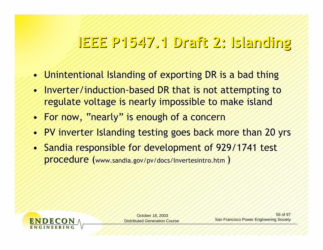
October 18, 2003Distributed Generation Course
55 of 97San Francisco Power Engineering SocietyEENNDDEE CCOONN
EE NN GG II NN EE EE RR II NN GG
IEEE P1547.1 Draft 2: IslandingIEEE P1547.1 Draft 2: Islanding
•• Unintentional Islanding of exporting DR is a bad thingUnintentional Islanding of exporting DR is a bad thing
•• Inverter/inductionInverter/induction--based DR that is not attempting to based DR that is not attempting to regulate voltage is nearly impossible to make islandregulate voltage is nearly impossible to make island
•• For now, “nearly” is enough of a concernFor now, “nearly” is enough of a concern
•• PV inverter Islanding testing goes back more than 20 yrsPV inverter Islanding testing goes back more than 20 yrs
•• Sandia responsible for development of 929/1741 test Sandia responsible for development of 929/1741 test procedure (procedure (www.www.sandiasandia..govgov//pvpv/docs//docs/InvertesintroInvertesintro..htmhtm ))

October 18, 2003Distributed Generation Course
56 of 97San Francisco Power Engineering SocietyEENNDDEE CCOONN
EE NN GG II NN EE EE RR II NN GG
IEEE P1547.1 Draft 2: IslandingIEEE P1547.1 Draft 2: Islanding
•• Resonant Tank circuit used to stabilize island Resonant Tank circuit used to stabilize island voltage and frequencyvoltage and frequency
•• Real load to generation match determines Real load to generation match determines operating voltageoperating voltage
•• Capacitance to Inductance match determines Capacitance to Inductance match determines operating frequencyoperating frequency
•• Quality factor, Q, defines circuit resonance:Quality factor, Q, defines circuit resonance:
kW
kVARkVARQ CL ×
=

October 18, 2003Distributed Generation Course
57 of 97San Francisco Power Engineering SocietyEENNDDEE CCOONN
EE NN GG II NN EE EE RR II NN GG
AntiAnti--Islanding Test CircuitIslanding Test Circuit
DRDR
S3S3
LR C
S2S2S1S1
SimulatedSimulatedUtilityUtility
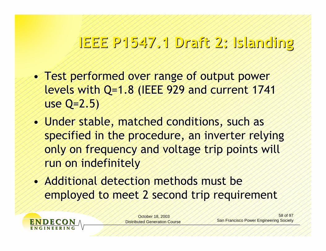
October 18, 2003Distributed Generation Course
58 of 97San Francisco Power Engineering SocietyEENNDDEE CCOONN
EE NN GG II NN EE EE RR II NN GG
IEEE P1547.1 Draft 2: IslandingIEEE P1547.1 Draft 2: Islanding
•• Test performed over range of output power Test performed over range of output power levels with Q=1.8 (IEEE 929 and current 1741 levels with Q=1.8 (IEEE 929 and current 1741 use Q=2.5)use Q=2.5)
•• Under stable, matched conditions, such as Under stable, matched conditions, such as specified in the procedure, an inverter relying specified in the procedure, an inverter relying only on frequency and voltage trip points will only on frequency and voltage trip points will run on indefinitely run on indefinitely
•• Additional detection methods must be Additional detection methods must be employed to meet 2 second trip requirementemployed to meet 2 second trip requirement

October 18, 2003Distributed Generation Course
59 of 97San Francisco Power Engineering SocietyEENNDDEE CCOONN
EE NN GG II NN EE EE RR II NN GG
IEEE P1547.1 Draft 2: IslandingIEEE P1547.1 Draft 2: Islanding
•• Test is intended to be detectionTest is intended to be detection--method method neutralneutral
•• Other methodOther method--specific or less rigorous tests are specific or less rigorous tests are being consideredbeing considered

October 18, 2003Distributed Generation Course
60 of 97San Francisco Power Engineering SocietyEENNDDEE CCOONN
EE NN GG II NN EE EE RR II NN GG
IEEE P1547.1 OutlineIEEE P1547.1 Outline
5.75.7 Reverse Power (for unintentional islanding)Reverse Power (for unintentional islanding)5.7.1 Reverse5.7.1 Reverse--Power Magnitude TestPower Magnitude Test
5.7.2 Reverse5.7.2 Reverse--Power Time TestPower Time Test
5.85.8 Cease to Energize Functionality and Loss of Cease to Energize Functionality and Loss of Phase Test RequirementsPhase Test Requirements
5.95.9 Reconnect Following Abnormal Condition Reconnect Following Abnormal Condition Disconnect Disconnect (restart magnitude and delay)(restart magnitude and delay)
5.105.10 HarmonicsHarmonics
5.115.11 Temperature Stability Test Temperature Stability Test
October 18, 2003Distributed Generation Course
61 of 97San Francisco Power Engineering SocietyEENNDDEE CCOONN
EE NN GG II NN EE EE RR II NN GG
IEEE P1547.1 OutlineIEEE P1547.1 Outline
6.0 Production Tests 6.0 Production Tests (simplified versions of Type (simplified versions of Type Tests)Tests)
6.1 Response to Abnormal Voltage6.1 Response to Abnormal Voltage
6.2 Response to Abnormal Frequency 6.2 Response to Abnormal Frequency
6.3 Synchronization6.3 Synchronization
6.4 Documentation 6.4 Documentation

October 18, 2003Distributed Generation Course
62 of 97San Francisco Power Engineering SocietyEENNDDEE CCOONN
EE NN GG II NN EE EE RR II NN GG
IEEE P1547.1 OutlineIEEE P1547.1 Outline
7 Commissioning Tests7 Commissioning Tests7.1 Verifications and Inspections7.1 Verifications and Inspections
7.2 Field Conducted Type and Production tests7.2 Field Conducted Type and Production tests
7.3 Permission from Area EPS operator to parallel DR7.3 Permission from Area EPS operator to parallel DR
7.4 Unintentional Islanding7.4 Unintentional Islanding7.4.17.4.1 Unintentional Islanding Procedure for Synchronous Unintentional Islanding Procedure for Synchronous
machinemachine7.4.27.4.2 Unintentional Islanding Procedure for InverterUnintentional Islanding Procedure for Inverter

October 18, 2003Distributed Generation Course
63 of 97San Francisco Power Engineering SocietyEENNDDEE CCOONN
EE NN GG II NN EE EE RR II NN GG
IEEE P1547.1 StatusIEEE P1547.1 Status
•• Writing Committee is preparing Draft 3 for Writing Committee is preparing Draft 3 for review at Nov 12review at Nov 12--14 workgroup meeting14 workgroup meeting
•• Section 5 (Type Tests) is fairly well developedSection 5 (Type Tests) is fairly well developed
•• Section 6 (Production Tests) has first cuts for Section 6 (Production Tests) has first cuts for most elements most elements
•• Section 7 (Commissioning Test) is under initial Section 7 (Commissioning Test) is under initial developmentdevelopment
•• Expect to have document approved by June Expect to have document approved by June 20052005
October 18, 2003Distributed Generation Course
64 of 97San Francisco Power Engineering SocietyEENNDDEE CCOONN
EE NN GG II NN EE EE RR II NN GG
IEEE P1547.2IEEE P1547.2
Thanks to Tom Basso and Richard FriedmanThanks to Tom Basso and Richard Friedman
Draft Application Guide For IEEE Std. 1547, Draft Application Guide For IEEE Std. 1547, Standard For Interconnecting Distributed Standard For Interconnecting Distributed Resources With Electric Power SystemsResources With Electric Power Systems

October 18, 2003Distributed Generation Course
65 of 97San Francisco Power Engineering SocietyEENNDDEE CCOONN
EE NN GG II NN EE EE RR II NN GG
IEEE P1547.2IEEE P1547.2
Scope:Scope:
This guide provides technical background and application details to support the understanding of IEEE 1547, Standard for Interconnecting Distributed Resources with Electric Power Systems.
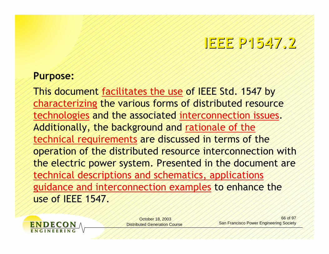
October 18, 2003Distributed Generation Course
66 of 97San Francisco Power Engineering SocietyEENNDDEE CCOONN
EE NN GG II NN EE EE RR II NN GG
IEEE P1547.2IEEE P1547.2
Purpose:This document facilitates the use of IEEE Std. 1547 by characterizing the various forms of distributed resource technologies and the associated interconnection issues. Additionally, the background and rationale of the technical requirements are discussed in terms of the operation of the distributed resource interconnection with the electric power system. Presented in the document are technical descriptions and schematics, applications guidance and interconnection examples to enhance the use of IEEE 1547.

October 18, 2003Distributed Generation Course
67 of 97San Francisco Power Engineering SocietyEENNDDEE CCOONN
EE NN GG II NN EE EE RR II NN GG
What P1547.2 is Intended to DoWhat P1547.2 is Intended to Do
• Providing technical background
• Providing application details
• Characterizing various forms of DR technologies
• Characterizing associated interconnection issues
• Discussing background and rationale of the technical requirements in terms of the operation of the interconnection
• Presenting good practice approaches
Support understanding and facilitate use of IEEE 1547 by
October 18, 2003Distributed Generation Course
68 of 97San Francisco Power Engineering SocietyEENNDDEE CCOONN
EE NN GG II NN EE EE RR II NN GG
What P1547.2 Will What P1547.2 Will NOTNOT DoDo
•• Interpret IEEE 1547Interpret IEEE 1547
•• Introduce new requirements to IEEE 1547Introduce new requirements to IEEE 1547
•• Address issues not covered in IEEE 1547, other Address issues not covered in IEEE 1547, other than as needed to help enhance the user's than as needed to help enhance the user's understanding of IEEE 1547understanding of IEEE 1547
•• Provide a "guarantee" that IEEE 1547 Provide a "guarantee" that IEEE 1547 requirements will be metrequirements will be met

October 18, 2003Distributed Generation Course
69 of 97San Francisco Power Engineering SocietyEENNDDEE CCOONN
EE NN GG II NN EE EE RR II NN GG 69
Other IEEE SCC21 Other IEEE SCC21 Interconnection ProjectsInterconnection Projects
TTiittllee SSccooppee aanndd PPuurrppoossee PP11554477..33:: DDrraafftt GGuuiiddee ffoorr MMoonniittoorriinngg,, IInnffoorrmmaattiioonn EExxcchhaannggee aanndd CCoonnttrrooll ooff DDiissttrriibbuutteedd RReessoouurrcceess IInntteerrccoonnnneecctteedd wwiitthh EElleeccttrriicc PPoowweerr SSyysstteemmss
•• TThhiiss ddooccuummeenntt pprroovviiddeess gguuiiddeelliinneess ffoorr mmoonniittoorriinngg,, iinnffoorrmmaattiioonn eexxcchhaannggee,, aanndd ccoonnttrrooll ffoorr ddiissttrriibbuutteedd rreessoouurrcceess ((DDRR)) iinntteerrccoonnnneecctteedd wwiitthh eelleeccttrriicc ppoowweerr ssyysstteemmss ((EEPPSS)).. •• TThhiiss ddooccuummeenntt ffaacciilliittaatteess tthhee iinntteerrooppeerraabbiilliittyy ooff oonnee oorr mmoorree ddiissttrriibbuutteedd rreessoouurrcceess iinntteerrccoonnnneecctteedd wwiitthh eelleeccttrriicc ppoowweerr ssyysstteemmss.. IItt ddeessccrriibbeess ffuunnccttiioonnaalliittyy,, ppaarraammeetteerrss aanndd mmeetthhooddoollooggiieess ffoorr mmoonniittoorriinngg,, iinnffoorrmmaattiioonn eexxcchhaannggee aanndd ccoonnttrrooll ffoorr tthhee iinntteerrccoonnnneecctteedd ddiissttrriibbuutteedd rreessoouurrcceess wwiitthh,, oorr aassssoocciiaatteedd wwiitthh,, eelleeccttrriicc ppoowweerr ssyysstteemmss.. DDiissttrriibbuutteedd rreessoouurrcceess iinncclluuddee ssyysstteemmss iinn tthhee aarreeaass ooff ffuueell cceellllss,, pphhoottoovvoollttaaiiccss,, wwiinndd ttuurrbbiinneess,, mmiiccrroottuurrbbiinneess,, ootthheerr ddiissttrriibbuutteedd ggeenneerraattoorrss,, aanndd,, ddiissttrriibbuutteedd eenneerrggyy ssttoorraaggee ssyysstteemmss..
October 18, 2003Distributed Generation Course
70 of 97San Francisco Power Engineering SocietyEENNDDEE CCOONN
EE NN GG II NN EE EE RR II NN GG
• Dr. Richard DeBlasio [email protected] (303) 275 - 4333• Mr. Tom S. Basso [email protected] (303) 275 - 3753
• IEEE SCC21 -- IEEE Standards Coordinating Committee 21 on Fuel Cells, Photovoltaics, Dispersed Generation, & Energy Storage http://grouper.ieee.org/groups/scc21/
• 1547 web sites • http://grouper.ieee.org/groups/scc21/1547• http://grouper.ieee.org/groups/scc21/1547.1/1547.1_index.html• http://grouper.ieee.org/groups/scc21/1547.2/1547.2_index.html• http://grouper.ieee.org/groups/scc21/1547.3/1547.3_index.html
70
SCC 21 Contact InformationSCC 21 Contact Information
October 18, 2003Distributed Generation Course
71 of 97San Francisco Power Engineering SocietyEENNDDEE CCOONN
EE NN GG II NN EE EE RR II NN GG
UL 1741UL 1741
Standard for Inverters, Converters and Standard for Inverters, Converters and Controllers for Use In Independent Controllers for Use In Independent Power SystemsPower Systems
(Thanks to Tim Zgonena of UL)(Thanks to Tim Zgonena of UL)
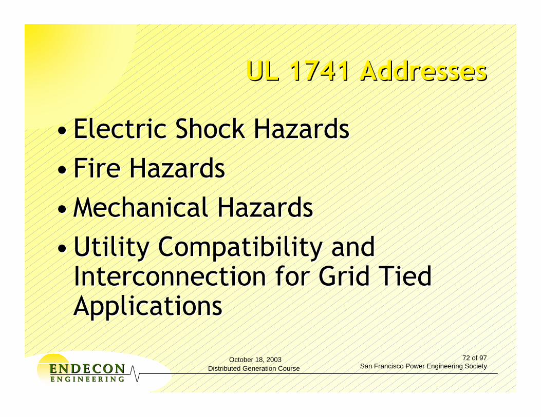
October 18, 2003Distributed Generation Course
72 of 97San Francisco Power Engineering SocietyEENNDDEE CCOONN
EE NN GG II NN EE EE RR II NN GG
UL 1741 AddressesUL 1741 Addresses
•• Electric Shock HazardsElectric Shock Hazards•• Fire HazardsFire Hazards•• Mechanical HazardsMechanical Hazards•• Utility Compatibility and Utility Compatibility and
Interconnection for Grid Tied Interconnection for Grid Tied ApplicationsApplications
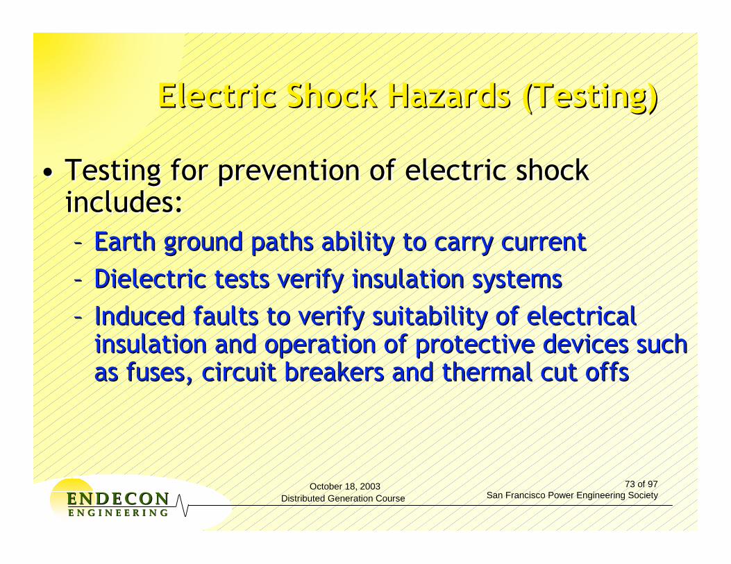
October 18, 2003Distributed Generation Course
73 of 97San Francisco Power Engineering SocietyEENNDDEE CCOONN
EE NN GG II NN EE EE RR II NN GG
Electric Shock Hazards (Testing)Electric Shock Hazards (Testing)
•• Testing for prevention of electric shock Testing for prevention of electric shock includes:includes:–– Earth ground paths ability to carry currentEarth ground paths ability to carry current–– Dielectric tests verify insulation systemsDielectric tests verify insulation systems–– Induced faults to verify suitability of electrical Induced faults to verify suitability of electrical
insulation and operation of protective devices such insulation and operation of protective devices such as fuses, circuit breakers and thermal cut offsas fuses, circuit breakers and thermal cut offs
October 18, 2003Distributed Generation Course
74 of 97San Francisco Power Engineering SocietyEENNDDEE CCOONN
EE NN GG II NN EE EE RR II NN GG
Electric Shock Hazards Electric Shock Hazards (Construction)(Construction)
•• Enclosure and BarriersEnclosure and Barriers
•• Insulate accessible live parts for both Insulate accessible live parts for both end users and service personnelend users and service personnel
•• Insulation between circuits of different Insulation between circuits of different potential or separation of circuitspotential or separation of circuits
•• Markings and labelingMarkings and labeling
October 18, 2003Distributed Generation Course
75 of 97San Francisco Power Engineering SocietyEENNDDEE CCOONN
EE NN GG II NN EE EE RR II NN GG
Fire HazardsFire Hazards
•• Verification of normal operating temperaturesVerification of normal operating temperatures
•• Acceptable operation of transformers under Acceptable operation of transformers under short circuit and overload conditionsshort circuit and overload conditions
•• Under no circumstances shall a product emit Under no circumstances shall a product emit sparks, flames or molten metal sparks, flames or molten metal
October 18, 2003Distributed Generation Course
76 of 97San Francisco Power Engineering SocietyEENNDDEE CCOONN
EE NN GG II NN EE EE RR II NN GG
Mechanical HazardsMechanical Hazards–– Sharp EdgesSharp Edges
–– Mounting means Mounting means
–– StabilityStability
October 18, 2003Distributed Generation Course
77 of 97San Francisco Power Engineering SocietyEENNDDEE CCOONN
EE NN GG II NN EE EE RR II NN GG
•• Many of the performance issues Many of the performance issues associated with the grid interactive associated with the grid interactive operation of DG products are important operation of DG products are important Safety Issues. This is unlike many other Safety Issues. This is unlike many other product categories covered by UL product categories covered by UL Standards.Standards.
UL 1741UL 1741
October 18, 2003Distributed Generation Course
78 of 97San Francisco Power Engineering SocietyEENNDDEE CCOONN
EE NN GG II NN EE EE RR II NN GG
Utility Compatibility and Utility Compatibility and Interconnection ConcernsInterconnection Concerns
•• The following performance parameters The following performance parameters are safety issuesare safety issues–– Utility operating voltage and frequency Utility operating voltage and frequency
parametersparameters–– Islanding protectionIslanding protection
–– Output Power QualityOutput Power Quality
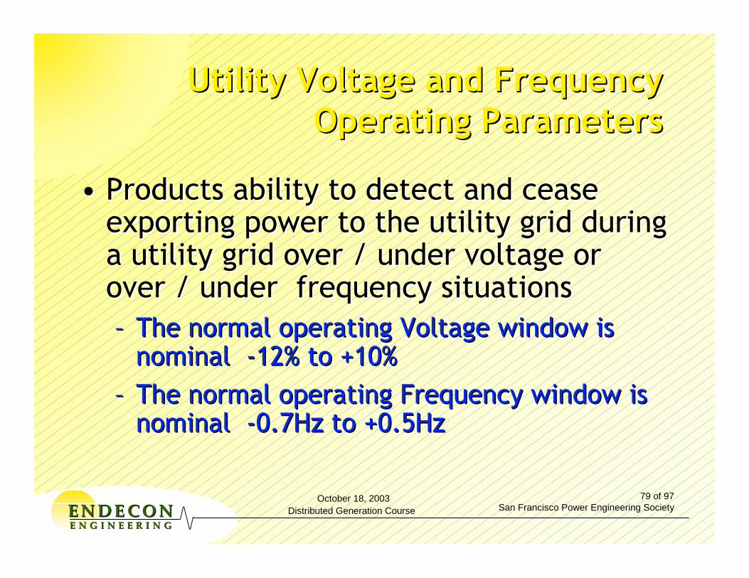
October 18, 2003Distributed Generation Course
79 of 97San Francisco Power Engineering SocietyEENNDDEE CCOONN
EE NN GG II NN EE EE RR II NN GG
Utility Voltage and Frequency Utility Voltage and Frequency Operating ParametersOperating Parameters
•• Products ability to detect and cease Products ability to detect and cease exporting power to the utility grid during exporting power to the utility grid during a utility grid over / under voltage or a utility grid over / under voltage or over / under frequency situationsover / under frequency situations–– The normal operating Voltage window is The normal operating Voltage window is
nominal nominal --12% to +10%12% to +10%–– The normal operating Frequency window is The normal operating Frequency window is
nominal nominal --0.7Hz to +0.5Hz0.7Hz to +0.5Hz
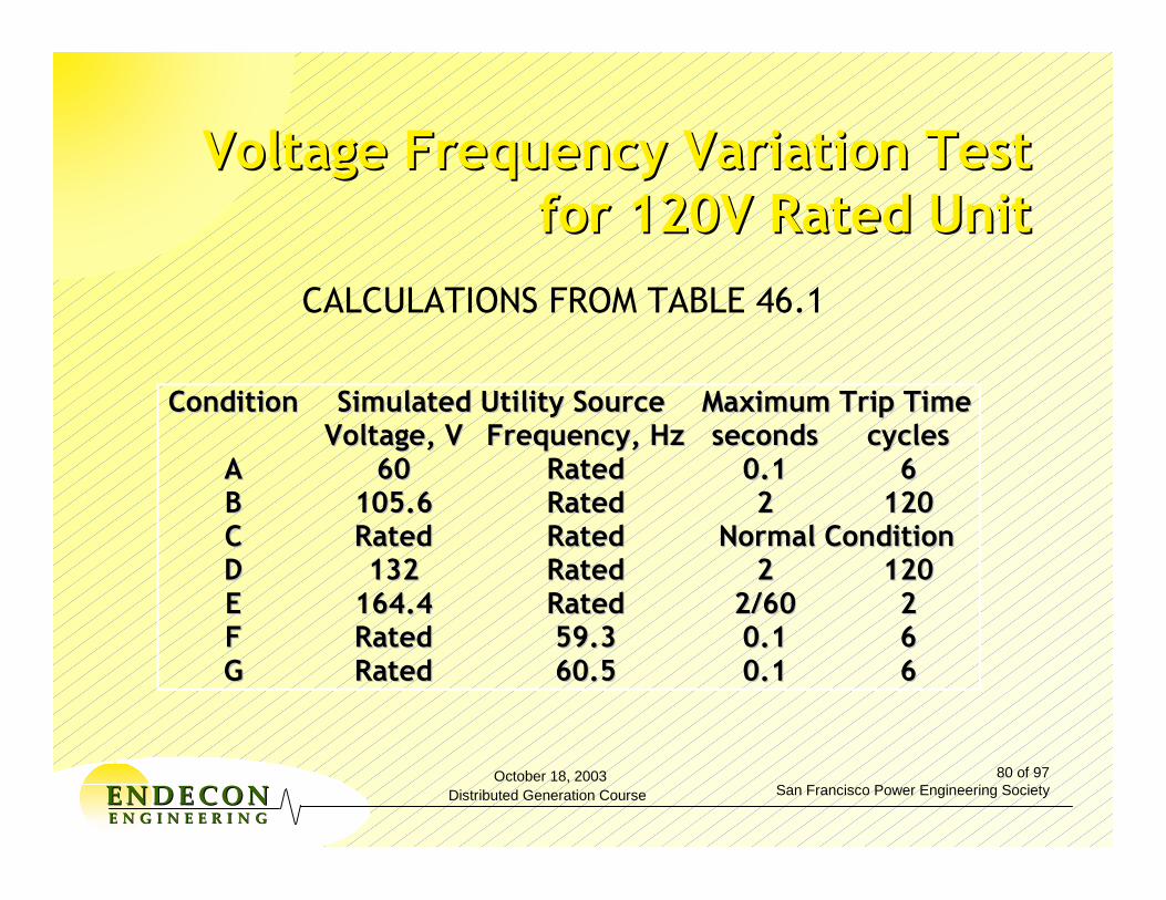
October 18, 2003Distributed Generation Course
80 of 97San Francisco Power Engineering SocietyEENNDDEE CCOONN
EE NN GG II NN EE EE RR II NN GG
Voltage Frequency Variation Test Voltage Frequency Variation Test for 120V Rated Unitfor 120V Rated Unit
SSiimmuullaatteedd UUttiilliittyy SSoouurrccee MMaaxxiimmuumm TTrriipp TTiimmeeCCoonnddiittiioonn VVoollttaaggee,, VV FFrreeqquueennccyy,, HHzz sseeccoonnddss ccyycclleess
AA 6600 RRaatteedd 00..11 66 BB 110055..66 RRaatteedd 22 112200 CC RRaatteedd RRaatteedd NNoorrmmaall CCoonnddiittiioonn DD 113322 RRaatteedd 22 112200 EE 116644..44 RRaatteedd 22//6600 22 FF RRaatteedd 5599..33 00..11 66 GG RRaatteedd 6600..55 00..11 66
CALCULATIONS FROM TABLE 46.1
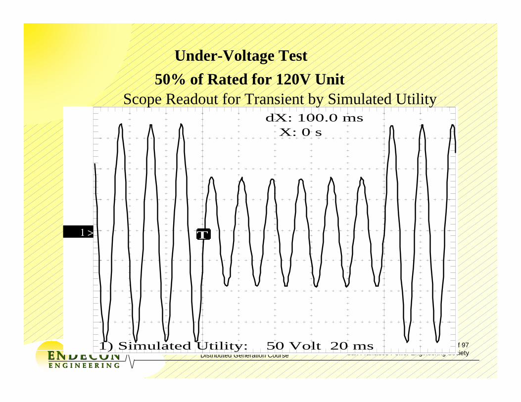
October 18, 2003Distributed Generation Course
81 of 97San Francisco Power Engineering SocietyEENNDDEE CCOONN
EE NN GG II NN EE EE RR II NN GG
T1 >
1) Simulated Utility: 50 Volt 20 ms
dX: 100.0 ms X: 0 s
Under-Voltage Test
Scope Readout for Transient by Simulated Utility50% of Rated for 120V Unit
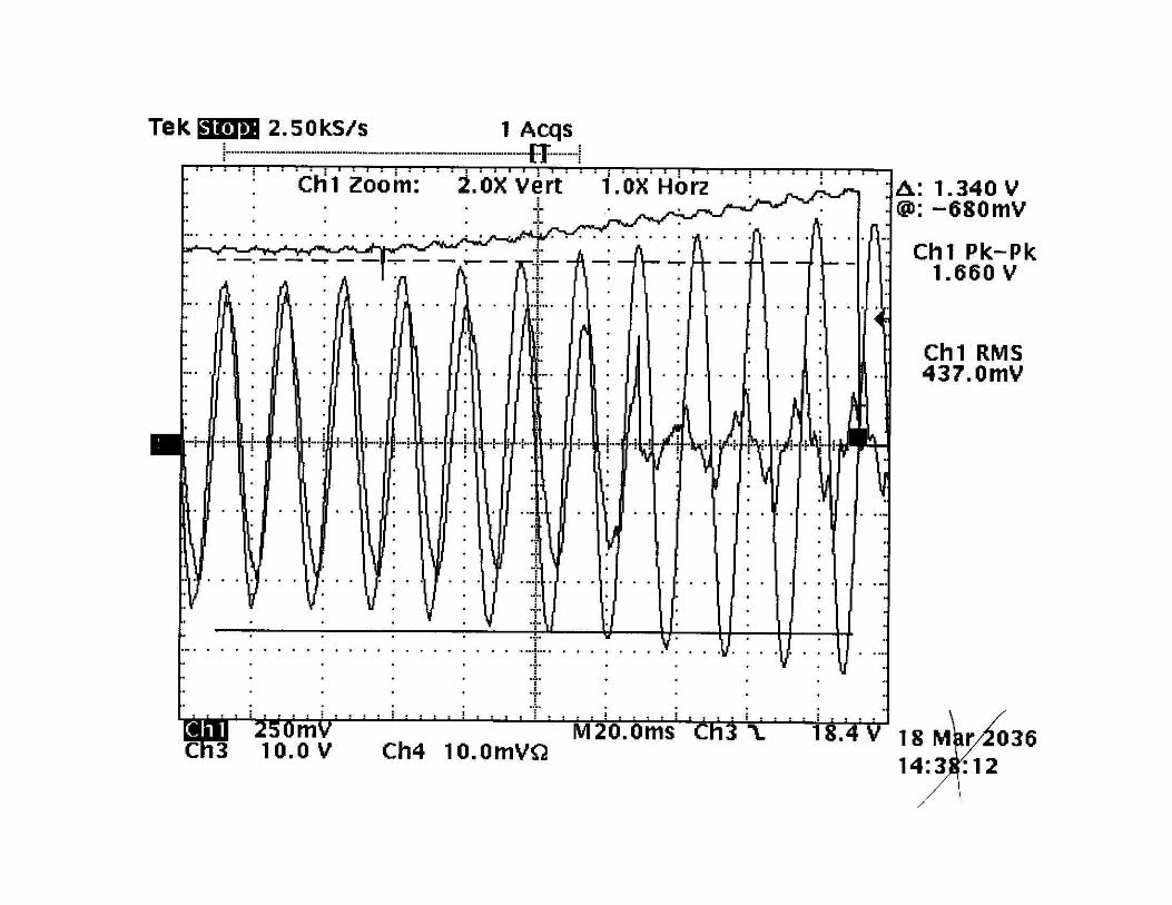
October 18, 2003Distributed Generation Course
82 of 97San Francisco Power Engineering SocietyEENNDDEE CCOONN
EE NN GG II NN EE EE RR II NN GG
October 18, 2003Distributed Generation Course
83 of 97San Francisco Power Engineering SocietyEENNDDEE CCOONN
EE NN GG II NN EE EE RR II NN GG
Islanding ProtectionIslanding Protection
•• IslandingIslanding is when a distributed source continues is when a distributed source continues to operate, feeding power into a portion of the to operate, feeding power into a portion of the grid when the utility source is no longer grid when the utility source is no longer present. This situation presents many hazards present. This situation presents many hazards including lethal electric shock to utility service including lethal electric shock to utility service personnel that think that the load side of the personnel that think that the load side of the utility transmission line is “electrically dead.”utility transmission line is “electrically dead.”
•• Utility and DG equipment damage.Utility and DG equipment damage.
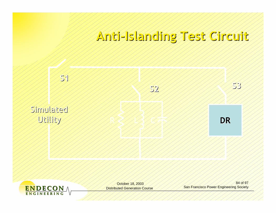
October 18, 2003Distributed Generation Course
84 of 97San Francisco Power Engineering SocietyEENNDDEE CCOONN
EE NN GG II NN EE EE RR II NN GG
AntiAnti--Islanding Test CircuitIslanding Test Circuit
SimulatedSimulatedUtilityUtility DRDR
S3S3
LR C
S2S2S1S1
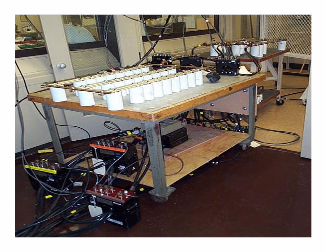

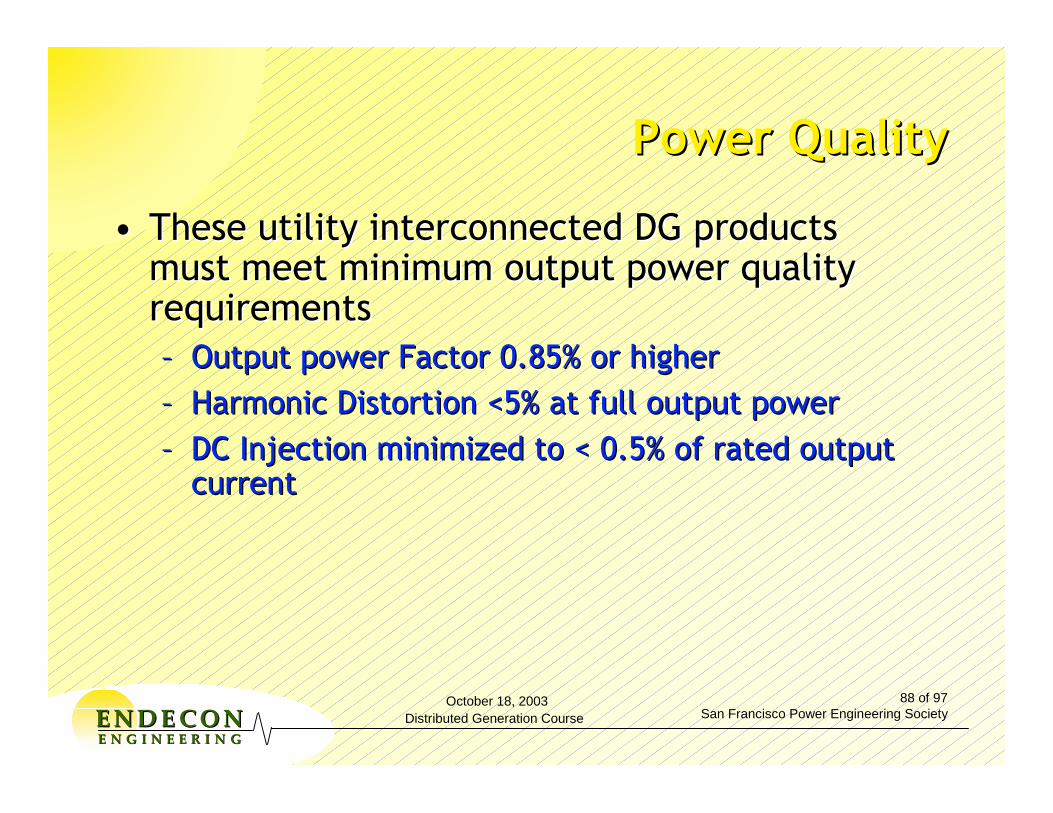
October 18, 2003Distributed Generation Course
88 of 97San Francisco Power Engineering SocietyEENNDDEE CCOONN
EE NN GG II NN EE EE RR II NN GG
Power QualityPower Quality
•• These utility interconnected DG products These utility interconnected DG products must meet minimum output power quality must meet minimum output power quality requirements requirements –– Output power Factor 0.85% or higherOutput power Factor 0.85% or higher–– Harmonic Distortion <5% at full output power Harmonic Distortion <5% at full output power –– DC Injection minimized to < 0.5% of rated output DC Injection minimized to < 0.5% of rated output
currentcurrent

October 18, 2003Distributed Generation Course
89 of 97San Francisco Power Engineering SocietyEENNDDEE CCOONN
EE NN GG II NN EE EE RR II NN GG
UL 1741 Covers UL 1741 Covers Utility Interactive, StandUtility Interactive, Stand--alone, alone,
and Multiand Multi--Mode Products.Mode Products.
•• Utility InteractiveUtility Interactive -- Products that operate in Products that operate in parallel with or backfeed power to the utility parallel with or backfeed power to the utility grid to supply common loads.grid to supply common loads.
•• Stand AloneStand Alone -- Products that supply power to Products that supply power to loads independent of the utility grid.loads independent of the utility grid.
•• MultimodeMultimode -- Products that can operate in both Products that can operate in both utility interactive and standutility interactive and stand--alone modes in case alone modes in case of utility failure. of utility failure.

October 18, 2003Distributed Generation Course
90 of 97San Francisco Power Engineering SocietyEENNDDEE CCOONN
EE NN GG II NN EE EE RR II NN GG
UL 1741 Expansion to Cover the UL 1741 Expansion to Cover the Interconnect of All Types of DGInterconnect of All Types of DG
•• UL1741 New Title UL1741 New Title -- The Standard For Inverters, The Standard For Inverters, Converters and Controllers For Use In Independent Converters and Controllers For Use In Independent Power Production Systems.Power Production Systems.–– Photovoltaic ModulesPhotovoltaic Modules
–– Fuel CellsFuel Cells
–– MicroMicro--turbinesturbines
–– Wind and Hydro TurbinesWind and Hydro Turbines
–– Engine GenEngine Gen--Set Interconnect ControllersSet Interconnect Controllers
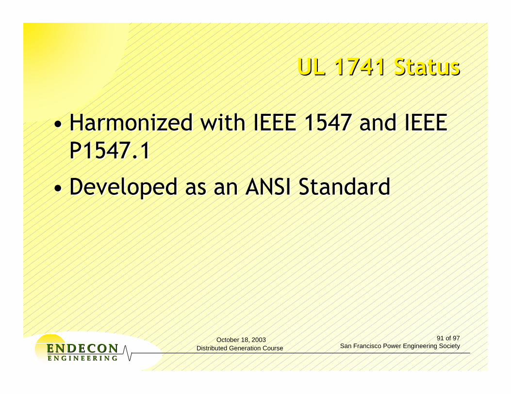
October 18, 2003Distributed Generation Course
91 of 97San Francisco Power Engineering SocietyEENNDDEE CCOONN
EE NN GG II NN EE EE RR II NN GG
UL 1741 StatusUL 1741 Status
•• Harmonized with IEEE 1547 and IEEE Harmonized with IEEE 1547 and IEEE P1547.1P1547.1
•• Developed as an ANSI StandardDeveloped as an ANSI Standard
October 18, 2003Distributed Generation Course
92 of 97San Francisco Power Engineering SocietyEENNDDEE CCOONN
EE NN GG II NN EE EE RR II NN GG
•• UL1741 is being harmonized with UL1741 is being harmonized with IEEE 1547 and IEEE P1547.1IEEE 1547 and IEEE P1547.1
October 18, 2003Distributed Generation Course
93 of 97San Francisco Power Engineering SocietyEENNDDEE CCOONN
EE NN GG II NN EE EE RR II NN GG
Tim Zgonena Tim Zgonena
Underwriters Laboratories Inc.Underwriters Laboratories Inc.333 333 PfingstenPfingsten Rd.Rd.Northbrook, IL 60062Northbrook, IL 60062
847847--272272--8800 ext. 430518800 ext. 43051timothy.p.timothy.p.zgonenazgonena@[email protected]
For More Information...For More Information...


On the Road to On the Road to ‘Plug‘Plug--&&--Play’ Play’ DGDG??
Anthony Mazy, PECALIFORNIA PUBLIC UTILITIES COMMISSION
Office of Ratepayer Advocates
An epilogue . . .An epilogue . . .
. . . about the limits of:
what we knowwhat we agree uponwhat we believe
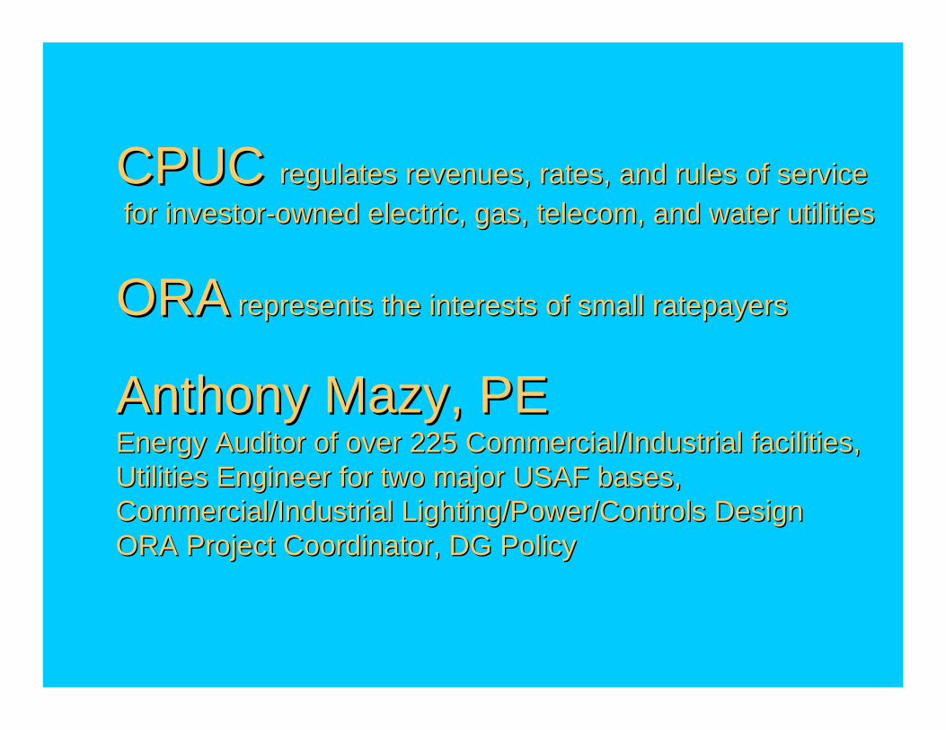
CPUC CPUC regulates revenues, rates, and rules of serviceregulates revenues, rates, and rules of servicefor investorfor investor--owned electric, gas, telecom, and water utilitiesowned electric, gas, telecom, and water utilities
ORAORA represents the interests of small ratepayersrepresents the interests of small ratepayers
Anthony Mazy, PEAnthony Mazy, PEEnergy Auditor of over 225 Commercial/Industrial facilities, Energy Auditor of over 225 Commercial/Industrial facilities, Utilities Engineer for two major USAF bases, Utilities Engineer for two major USAF bases, Commercial/Industrial Lighting/Power/Controls DesignCommercial/Industrial Lighting/Power/Controls DesignORA Project Coordinator, DG PolicyORA Project Coordinator, DG Policy
DisclaimerDisclaimer
The Opinions Expressed
Are Those of the Individual Speaker
and Do Not Necessarily Represent The Opinions
of the California Public Utilities Commission,
The Office of Ratepayer Advocate,
or Their Managements
We don’t know as much as we We don’t know as much as we like to think we dolike to think we do
Industry (or gov’t) isn’t well documentedUtilities, Developers, Regulators all make decisions without adequate informationExample: Documentation of Unintended Islanding
Example:Example:Documentation of IslandingDocumentation of Islanding
(Unintended Islanding, not Microgrids)(Unintended Islanding, not Microgrids)
Utility Engineers universally aver existence, significance of islandingAcademic researchers universally deride probable significanceAlmost no actual documentation exists

We disagree more than we We disagree more than we really like to talk aboutreally like to talk about
Technical decisions have business implicationsInstitutions are highly risk-averseExample: Utility Discretion

Example:Example:The Problem with “Discretion”The Problem with “Discretion”
How to distinguish between . . .How to distinguish between . . .
“Good” DiscretionResolve problems with
andUndefined situations New situationsUnintended unfairness
“Bad” Discretion(i.e., “Market Power”)
Reward affiliatesPunish competitorsRogue individuals

We have radically divergent We have radically divergent beliefs about what’sbeliefs about what’s
. . . “good,” . . . “good,”
. . . “progress,” and. . . “progress,” and
. . . “the future”. . . “the future”“Well-bred people never discuss their religion, money, or politics”DG as a triple-pointExample: T&D Architecture

Example:Example:
T & D ArchitectureT & D ArchitectureShould It Continue to
“Transmit” & “Distribute” “Public Utility” Power to
Retail Customers or
With:
Hierarchical structure, protectionNominally “predictable” power flow
“Low Cost” Strategy
Should It Evolve into a “Physical Marketplace”
Between “Willing Sellers” and “Willing Buyers” of
Competitive Energy With:
Negotiable structure, protectionExplicitly unpredictable power flow
“High Value” Strategy
The UpshotThe Upshot
Developers and Utilities frequently disagree about . . .– What Rule 21 is trying to accomplish,
– What Rule 21 means, and even
– What Rule 21 says.
Should Not Be Cause for Despair!

Example:Example:How “nonHow “non--exporting”?exporting”?
Rule 21 includes “screens” for Simplified InterconnectionScreen 2: “Will power be exported across the PCC?”If “No,” four options, three implicitly addressing some export.
Bottom LineBottom Line
Only the CPUC sets Rules for utility serviceRule 21 is the only applicable interconnection ruleRule 2, etc., apply just as they apply to all other electric service installations“Interpretations” of Rule 21 must be fair, reasonable, and consistent

Where to Get More InformationWhere to Get More Information
California Attorney General investigates violations of state lawCPUC Consumer Affairs Board, investigates violations of regulatory rules, rates, or utility service standardsCPUC Energy Division investigates noncompliance with Commission policiesCPUC Office of Ratepayer Advocates investigates abusive, unfair, or unreasonable utility policies or practices
For Further Assistance:For Further Assistance:
Write: Anthony Mazy, PEProject Coordinator, DG PolicyOffice of Ratepayer AdvocatesCalifornia Public Utilities Commission505 Van Ness Avenue, 4th FloorSan Francisco, California 94102
E-mail: [email protected]
Or, Call: (415) 703-3036


