
1
Designing Heterogeneous Sensor Networks for Estimating and
Predicting Path Travel Time Dynamics: An Information-Theoretic
Modeling Approach
Tao Xinga, Xuesong Zhou
b,*
aDepartment of Civil and Environmental Engineering, University of Utah, Salt Lake City, UT 84112-0561,USA bDepartment of Civil and Environmental Engineering, University of Utah, Salt Lake City, UT 84112-0561, USA
Abstract
With a particular emphasis on the end-to-end travel time prediction problem, this paper proposes an information-
theoretic sensor location model that aims to maximize information gains from a set of point, point-to-point and
probe sensors in a traffic network. Based on a Kalman filtering structure, the proposed measurement and
information quantification models explicitly take into account several important sources of errors in the travel time
estimation/prediction process, such as the uncertainty associated with prior travel time estimates, measurement
errors and sampling errors. After thoroughly examining a number of possible measures of information gain, this
paper selects a path travel time prediction uncertainty criterion to construct a joint sensor location and travel time
estimation/prediction framework. We further discuss how to quantify information gain for steady state historical
databases and point-to-point sensors with multiple paths, and a heuristic beam-search algorithm is developed to
solve the combinatorial sensor selection problem. A number of illustrative examples are used to demonstrate the
effectiveness of the proposed methodology.
Key words: travel time prediction, sensor network design, automatic vehicle identification sensors, automatic vehicle location sensors
1. Introduction
1.1. Motivation
To provide effective traffic congestion mitigation strategies, transportation planning organizations and traffic
management centers need to (1) reliably estimate and predict network-wide traffic conditions and (2) effectively
inform and divert travelers to avoid recurring and non-recurring congestion. Traffic monitoring systems provide
fundamental data inputs for public agencies to measure time-varying traffic network flow patterns and accordingly
generate coordinated control strategies. In this paper, we focus on a series of critical and challenging modeling
issues in traffic sensor network design, in particular, how to locate different types of detectors to improve path travel
time prediction accuracy. Reliable end-to-end trip travel time information is critically needed in a wide range of
intelligent transportation system applications, such as personalized route guidance and pre-trip traveler information
provision.
Based on the types of measurement data, traffic sensors can be categorized into three groups, namely point
sensors, point-to-point sensors, and probe sensors. Point sensors collect vehicle speed (more precisely, time-mean
speed), volume and road occupancy data at fixed locations. With point detectors having significant failure rates,
existing in-pavement and road-side traffic detectors are typically instrumented on a small subset of freeway links.
Point-to-point sensors can track the identities of vehicles through mounted transponder tags, license plate numbers,
or mobile phone Bluetooth signals, as vehicles pass multiple but non-contiguous reader stations. A raw tag read
typically records a vehicle ID number, the related time stamp, and the location. If two readers at different locations
sequentially identify the same probe vehicle, then the corresponding data reads can be fused to calculate the reader-
to-reader travel time and the counts of identified vehicles between instrumented points.
Automatic license plate matching techniques have been used in the traffic surveillance field since the 1970s, and
many statistical and heuristic methods have been proposed to reduce reading errors to provide reliable data
association (Turner et al., 1998). Many feature-based vision and pattern recognition algorithms (e.g. Coifman et al.,
1998) have been developed to track individual vehicle trajectories using camera surveillance data. Radio Frequency

T. Xing, X. Zhou / Transportation Research Part B 00 (2011) 000–000
2
Identification (RFID) technologies first appeared in Automated Vehicle Identification (AVI) applications during the
1980s and has become a mature traffic surveillance technology that produces various traffic measures with high
accuracy and reliability. Currently, many RFID-based AVI systems are widely deployed in road pricing, parking lot
management, as well as real-time travel time information provision. For instance, prior to 2001, around 51 AVI sites
were installed and approximately 48,000 tags had been distributed to users in San Antonio, United States, which
represents a 5% market penetration rate. Additionally, Houston’s TranStar fully relies on AVI data to provide travel
time information currently (Haas et al., 2001). Many recent studies (e.g. Wasson et al., 2008, Haghani et al., 2010)
started to use mobile phone Media Access Control (MAC) addresses as unique traveler identifiers to track travel
time for vehicles and pedestrians.
Many Automatic Vehicle Location (AVL) technologies, such as Global Positioning System (GPS), and
electronic Distance Measuring Instruments (DMI’s) provide new possibilities for traffic monitoring to semi-
continuously obtain detailed passing time and location information along individual vehicle trajectories. As the
personal navigation market grows rapidly, probe data from in-vehicle Personal Navigation Devices (PND) and cell
phones become more readily available for continuous travel time measurement. On the other hand, privacy concerns
and expensive one-time installation costs are two important disadvantages influencing the AVL deployment
progress.
1.2. Literature review
Essentially, any application of real-time traffic measurements for supporting Advanced Traveler Information
Systems (ATIS) and Advanced Traffic Management Systems (ATMS) functionalities involves the estimation and/or
prediction of traffic states. Depending on underlying traffic process assumptions, the existing traffic state estimation
and prediction models can be classified into three major approaches: (1) approach purely based on statistical
methods, focusing on travel time forecasting, (2) approach based on macroscopic traffic flow models, focusing on
traffic flow estimation on successive segments of a freeway corridor, (3) approach based on dynamic traffic
assignment models, focusing on wide-area estimation of origin-destination trip demand and route choice
probabilities so as to predict traffic network flow patterns for links with and without sensors. In this research, we are
interested in how to place different types of sensors to improve information gains for the first statistical method-
based travel time prediction applications.
In sensor location models for the second approach, significant attention (e.g., Liu and Danczyk, 2009, Danczyk
and Liu, 2011, and Leow et al., 2008) has been devoted to placing point detectors along a freeway corridor to
minimize the traffic measurement errors of critical traffic state variables, such as segment density and flow. The
traffic origin-destination (OD) matrix estimation problem is also closely related to the travel time estimation
problem under consideration. To determine the priority of point detector locations, there are a wide range of
selection criteria, to name a few, “traffic flow volume” and “OD coverage” criteria proposed by Lam and Lo (1990),
a “maximum possible relative error (MPRE)” criterion proposed by Yang et al. (1991) that aims calculate the
greatest possible deviation from an estimated demand table to the unknown true OD trip demand.
Based on the trace of the a posteriori covariance matrix produced in a Kalman filtering model, Zhou and List
(2010) proposed an information-theoretic framework for locating fixed sensors in the traffic OD demand estimation
problem. Related studies along this line include an early attempt by Eisenman et al. (2006) that uses a Kalman
filtering model to minimize the total demand estimation error in a dynamic traffic simulator and a recent study by
Fei and Mahmassani (2011) that considers additional criteria, such as OD demand coverage, within a multi-
objective decision making structure. Furthermore, in the travel time estimation problem, the Kalman filtering based
framework has also been employed by many researchers. For instance, an ensemble Kalman filtering model is
proposed by Work et al. (2008) to estimate freeway travel time with probe measurements.
Several recent studies have been conducted on the sensor location problem from different perspectives. Chen et
al. (2004) studied the AVI reader location problem for both travel time and OD estimation applications. They
presented the following three location section criteria: minimizing the number of AVI readers, maximizing the
coverage of OD pairs, and maximizing the number of AVI readings. To maximize the information captured with
regard to the network traffic conditions under budget constraints, Lu et al. (2006) formulated the roadside servers
locating problem as a two-stage problem. The first stage was a sensitivity analysis to identify a subset of links on
which the flows have large variability of travel demand, and more links were gradually selected to maximize the

T. Xing, X. Zhou / Transportation Research Part B 00 (2011) 000–000
3
overall sensor network coverage in the second stage. Sherali et al. (2006) proposed a discrete optimization approach
for locating AVI readers to estimate corridor travel times. They used a quadratic zero-one optimization model to
capture travel time variability along specified trips. In a recent study by Ban et al. (2009), link travel time estimation
errors are selected as the optimization criterion for point sensor location problems, and a dynamic programming-
based solution method is constructed to optimize the location of point sensors on link segments along a corridor. Li
and Ouyang (2011) proposed a reliable sensor location method that considers probabilistic sensor failures, and
developed a Lagrangian relaxation based solution algorithm.
1.3. Proposed approach
While significant progress has been made in formulating and solving the sensor location problem for travel time
estimation and prediction, a number of challenging theoretical and practical issues remain to be addressed.
First, the optimization criteria used in the existing sensor location models typically differ from those used in
travel time estimation and prediction. Due to the inconsistency between the two models, the potential of scarce
sensor resources might not be fully achieved in terms of maximizing information gain for travel time
estimation/prediction. For example, an AVI sensor location plan that maximizes sensor coverage does not
necessarily yield the least end-to-end travel time estimation and prediction uncertainty if there are multiple likely
paths between pairs of AVI sensors. As a result, a simplified but unified travel time estimation and prediction model
for utilizing different data sources is critically required as the underlying building block for the sensor network
design problem.
Second, most of the existing studies typically focus on real-time speed estimation errors (when using measured
speed from point sensors to approximate speed on adjacent segments without sensors), they do not explicitly take
into account uncertainty reduction and propagation in a heterogeneous sensor network with both point and point-to-
point travel time measurements, as well as possible error correlation between new and existing sensors.
Third, how to quantify the information loss in an integrated travel time and prediction process, especially under
non-recurring traffic conditions, has not received sufficient attention. Under recurring conditions, the traffic is more
likely to be estimated and predicted accurately for links with sensor measurements. For locations without sensors,
one can resort to historical information (e.g. through limited floating car studies) or adjacent sensors to approximate
traffic conditions. However, under non-recurring traffic conditions due to incidents or special events, without real-
time measurements from impacted locations, traffic management centers or traffic information provision companies
might still offer biased traffic information, based on outdated historical estimates or incorrect approximation from
unimpacted neighboring detectors.
By extending a Kalman filtering-based information theoretic approach proposed by Zhou and List (2010) for
OD demand estimation applications, this research focuses on how to analyze the information gain for real-time
travel time estimation and prediction problem with heterogeneous data sources. Since the classical information
theory proposed by Shannon (1948) on measuring information gain related to signal communications, the sensor
location problem has been an important and active research area in the fields of electrical engineering and
information science. Various measures have been used to quantify the value of sensor information in different
sensor network applications, where the unknown system states (e.g. the position and velocity of targets studied by
Hintz and McVey, 1991) can typically be directly measured by sensors. In comparison, sensing network-wide travel
time patterns is difficult in its own right because point sensors only provides a partial coverage of the entire traffic
state. Using AVI data involves complex spatial and temporal mapping from raw measurements, and AVL data are
not always available on a fixed set of links, especially under an early sensor network deployment stage.
There are a wide range of time series-based methods for traffic state estimation, and many studies (e.g. Okutani
and Stephanedes (1984); Zhang and Rice, 2003; Stathopoulos and Karlaftis, 2003) have been devoted to travel time
prediction using Kalman filtering and Bayesian learning approaches. To extract related statistics from complex
spatial and temporal travel time correlations, a recent study by Fei et al. (2011) extends the structure state space
model proposed by Zhou and Mahmassani (2007) to detect the structural deviations between the current and
historical travel times and apply a polynomial trend filter to construct the transition matrix and predict future travel
time. In this paper, we aim to present a unified Kalman filtering-based framework under both recurring and non-
recurring traffic conditions. More importantly, a spatial queue-based cumulative flow count diagram is introduced to
derive the important transition matrix for modelling traffic evolution under non-recurring congestions. Different

T. Xing, X. Zhou / Transportation Research Part B 00 (2011) 000–000
4
from existing data-driven or time-series-based methods, this paper derives a series of point-queue-model-based
analytical travel time transition equations, which lay out a core modeling building block for quantifying prediction
uncertainty. In addition, a steady-state uncertainty formula is presented to fully capture day-to-day uncertainty
evolution and convergence of the sensor network in a long-term horizon.
The remainder of this paper is organized as follows. The overall framework and notation are described in the
next section. In Sections 3 and 4, a Kalman filtering based travel time estimation and prediction model is presented
for both recurring and non-recurring traffic conditions. A comprehensive discussion of information measure models
is presented in Section 5. Section 6 describes the beam-search based sensor design model and solution algorithms.
Finally, the proposed model is further extended to some complex cases considering AVI and AVL sensors in
Section 7, followed by numerical experiment results on a test network shown in Section 8.
2. Notation and modeling framework overview
We first introduce the notation used in the travel time prediction and sensor network design problems.
2.1. Notation and problem statement
Sets and Subscripts:
N = set of nodes.
A = set of links.
m = number of links in set A.
'A = set of links with point sensors (e.g. loop detectors), 'A A .
''N = set of nodes with point-to-point sensors, ''N N .
'''A = set of links with reliable probe sensor data, '''A A .
'A = sets of links that have been equipped with point sensors, ' 'A A .
''N = sets of nodes that have been equipped with AVI sensors, ' 'N N .
'n , ''n , '''n = numbers of measurements, respectively, from point sensors, point-to-point sensors and probe
sensors.
n = number of total measurements, ' '' '''n n n n .
t = time index for state variables.
h = travel time prediction horizon.
d = subscript for day index.
o = subscript for origin index, o O , O = set of origin zones.
s = subscript for destination index, s S , S = set of destination zones.
a,b = subscript for link index, ,a b A .
i, j = subscript for node index, ,i j N .
k, λ = subscript for path.
p(i,j,k) = set of links belong to path k from node i to node j.
Estimation variables
,d at = travel time of link a on day d.
, , ,d o s kt = travel time on path k from origin o to destination s, on day d,
, , , ,
( , , )
d o s k d a
a p o s k
t t
.
Measurements
,'d ay = single travel time measurement from a point sensor on link a, on day d.
, , ,''d i j ky = single travel time measurement from a pair of AVI readers on path k and day d from node i to node j,
where the first and second AVI sensors are located at nodes i and node j, respectively.

T. Xing, X. Zhou / Transportation Research Part B 00 (2011) 000–000
5
,'''d ay = a set of travel time measurements from a probe sensor that contain map-matched travel time records on
links a on path k and day d from node i to node j, where ( , , )a p i j k .
Vector and matrix forms in Kalman filtering framework:
Yd = sensor measurement vector on day d, consisting of n elements.
Td = travel time vector on day d, consisting of m elements td,a.
dT = a priori estimate of the mean values in the travel time vector on day d, consisting of m elements.
dT = a posteriori estimate of the mean values in the travel time vector on day d, consisting of m elements.
h
dT = historical regular travel time estimates using data up to day d.
Vd = structural deviation on day d.
dP = a priori variance covariance matrix of travel time estimate, consisting of (m × m) elements.
dP = a posteriori error covariance matrix, i.e. conditional covariance matrix of estimation errors after including
measurements. = a priori variance covariance matrix of structure deviation, consisting of (m × m) elements. = a posteriori variance covariance matrix of structure deviation.
T = vector of regular historical mean travel time estimates, consisting of m elements, 0hT T .
P = error covariance matrix of historical travel time estimate, consisting of (m × m) elements, 0P P .
dH = sensor matrix that maps unknown travel times Td to measurements Yd, consisting of (n × m) elements.
Kd = updating gain matrix, consisting of (n × m) elements, on day d. NR
dK = updating matrix for non-recurring traffic estimations on day d.
( , )dL t t h = non-recurring traffic transition matrix from time t to t+h on day d.
wd = system evolution noise vector for link travel times, ~ (0, )d dw N Q .
Qd = system evolution noise variance-covariance matrix, on day d.
μd = non-recurring derivation evolution noise vector for link travel times, (0, )~ NR
d dN Q .
NR
dQ = non-recurring derivation evolution noise variance-covariance matrix, on day d.
,d aq = systematic travel time variance on link a.
εd = combined measurement error term, εd ~ N(0, Rd ) , on day d.
Rd = variance-covariance matrix for measurement errors, on day d.
Parameters and variables used in measurement and sensor design models
, , ,i j k a = path-link incidence coefficient, , , ,i j k a =1 if path k from node i to node j passes through link a, and 0
otherwise.
,'''d a = stochastic link traversing coefficient for GPS probe vehicles, ,''' 1d a if GPS probe vehicles pass
through link a on day d, and 0 otherwise.
, , ,d o s ke = path travel time estimation error on path k from origin o to destination s.
, ,o s kf = traffic flow volume on path k from origin o to destination s.
dTU = total path travel time estimation uncertainty on day d.
α = market penetration rate for vehicles equipped with AVI sensors/tags.
β = market penetration rate for vehicles equipped with AVL sensors.
l = subscript of sensor design solution index.
T. Xing, X. Zhou / Transportation Research Part B 00 (2011) 000–000
6
lX = lth
sensor design solution, represented by ', '', ''', ,lX A N A .
*X = optimal sensor design solution.
( )lz X = overall information gain (i.e. performance function) for a given sensor design scenario lX .
Consider a traffic network with multiple origins oO and destinations sS, as well as a set of nodes connected
by a set of directed links. We assume the following input data are available:
(1) The prior information on historical travel time estimates, including a vector of historical mean travel time
estimates T and the corresponding variance-covariance matrix P .
(2) The link sets with point sensor and point-to-point AVI sensor data, specified by 'A and "N .
(3) Estimated market penetration rate α for point-to-point AVI sensors.
(4) Estimated market penetration rate β for probe sensors, and set of links with accurate probe data '''A .
The sensor network to be designed and deployed will include additional point sensors and point-to-point
detectors that lead to sensor location sets of 'A and ''N , where ' 'A A , '' ''N N . In the new sensor network,
through GPS map-matching algorithms, GPS probe data can be converted from raw longitude/latitude location
readings to link travel time records on a set of links '''A . In this study, we assume that probe data will be available
through a certain data sharing program, (e.g. Herrera and Bayen, 2010), from vehicles equipped with Internet-
connected GPS navigation systems or GPS-enabled mobile phones. It should be noticed that, depending on the
underlying map-matching algorithm and data collection mechanism, only a subset of links in a network, denoted by'''A can produce reliable GPS map-matching results. For example, it is very difficult to distinguish driving vs.
walking mode on arterial streets through data from GPS-equipped mobile phones, so typically only travel time
estimates on freeway links are considered to be reliable in this case.
One of the key assumptions in our study is that the historical travel time information can be characterized by the
a priori mean vector T and the estimation error variance matrix P . If point sensor or point-to-point data are
available from sets 'A and "N , then we can construct the mean travel time vector T , and estimate the variance of
estimates in the diagonal elements of corresponding variance-covariance matrix P . For links without historical
sensor measurements, the travel time mean estimate can be approximated by using national or regional travel time
index (e.g. 1.2) and set the corresponding variance to a sufficient large value or infinity. One can assume zero for the
correlation of initial travel time estimates. In the case of a complete lack of historical demand information, we can
set 1( ) 0P .
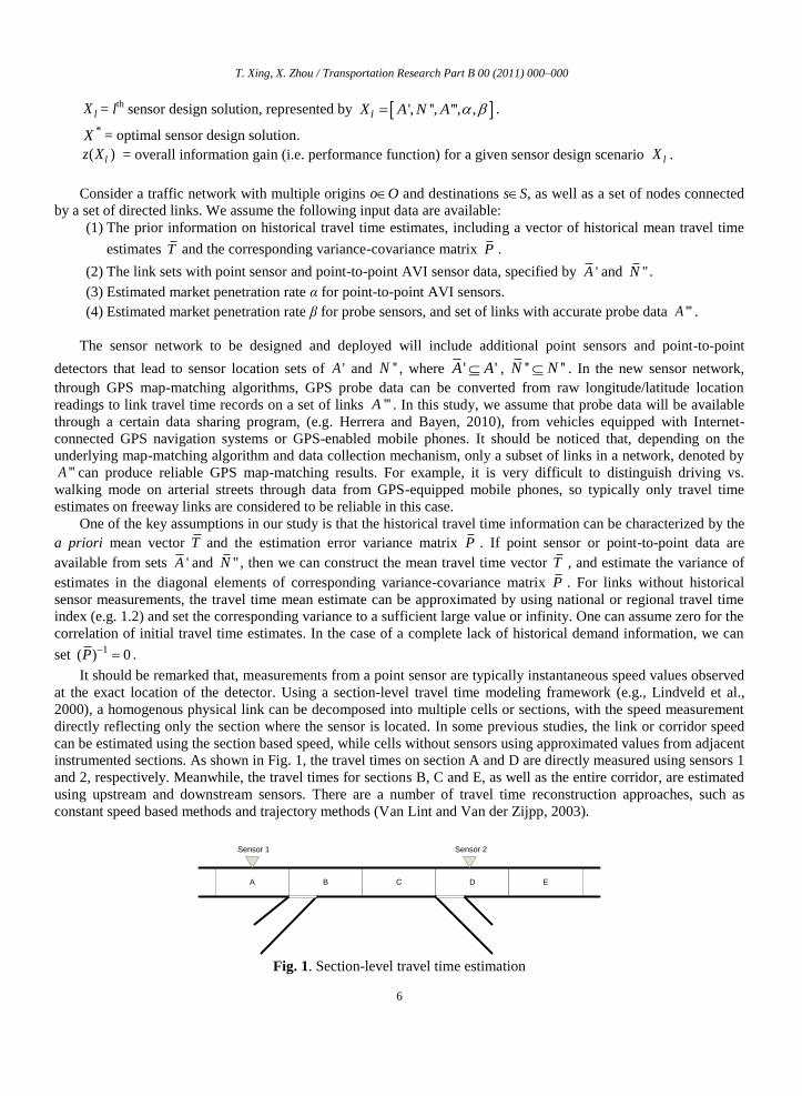
It should be remarked that, measurements from a point sensor are typically instantaneous speed values observed
at the exact location of the detector. Using a section-level travel time modeling framework (e.g., Lindveld et al.,
2000), a homogenous physical link can be decomposed into multiple cells or sections, with the speed measurement
directly reflecting only the section where the sensor is located. In some previous studies, the link or corridor speed
can be estimated using the section based speed, while cells without sensors using approximated values from adjacent
instrumented sections. As shown in Fig. 1, the travel times on section A and D are directly measured using sensors 1
and 2, respectively. Meanwhile, the travel times for sections B, C and E, as well as the entire corridor, are estimated
using upstream and downstream sensors. There are a number of travel time reconstruction approaches, such as
constant speed based methods and trajectory methods (Van Lint and Van der Zijpp, 2003).
A B C D E
Sensor 1 Sensor 2
Fig. 1. Section-level travel time estimation

T. Xing, X. Zhou / Transportation Research Part B 00 (2011) 000–000
7
In this study, for sections without point sensors, the above mentioned approximation error is modeled as prior
estimation errors, which can be obtained through a historical travel time database by considering other related links
such as adjacent links or links with similar characteristics. Furthermore, our proposed framework can be also easily
generalized to a section-based representation scheme, where a section in Fig. 1 can be viewed as a link in our link-
to-path-oriented modeling structure.
2.2. Generic state transition and measurement models
By adapting a structure state model for dynamic OD demand estimation by Zhou and Mahmassani (2007), this
study decomposes a true travel time pattern into three modeling components:
true travel time = regular recurring pattern + structural deviations + random fluctuations.
Under this assumption, travel time estimation/prediction can be studied in two categories: recurring traffic
conditions and non-recurring conditions. For travel time prediction under recurring conditions, structural deviation
is considered as zero, and the regular travel time patterns/profiles can be constructed based on historical data for
recurring traffic. On the other hand, for travel time prediction under non-recurring conditions, the structural
deviation is further modelled in this study as a function of time-dependent capacity and time-dependent demand.
Without loss of generality, this paper mainly focuses on time-dependent capacity reductions due to incidents, a
major source of non-recurring congestion.
To further jointly consider both recurring and non-recurring traffic conditions in the sensor location problem,
the overall system uncertainty under a certain sensor design is modeled as a probabilistic combination of recurring
and non-recurring uncertainty measures:
overall system prediction uncertainty =
(1 )NR uncertainty under recurring conditions + NR uncertainty under non-recurring conditions,
where NR represents the given probability of non-recurring events.
(i) State transition model
The state transition model of the travel time is written as
( ) ( ) ( ) , (0, )h
d d d d d dT t T t V t w w N Q (1)
In Eq. (1), the travel time for each link is represented as a combination of three components: regular pattern,
structural deviation and random fluctuation. The regular pattern ( )h
dT t is the time-dependent historical travel time
average which is determined by the day-to-day regular traffic demand and capacity. For non-recurring traffic
conditions, a structural deviation ( )d
V t exists due to non-recurring congestion sources such as incidents, work zones
and severe weathers. Considering a stationary congestion pattern, this study assumes that wd follows a normal
distribution with zero-mean and a variance-covariance matrix Qd. Qd corresponds to random travel time variation
magnitude, which is further determined by dynamics and stochasticity in the underlying traffic demand and road
capacity supply. For example, the travel time variations are more significant on a congested freeway link with close-
to-capacity demand flow volume, compared to a rural highway segment with low traffic volume and sufficient
capacity where the speed limit could yield a good estimate most of the time. More specifically, qd,a , the (diagonal)
variance elements of the matrix Qd, exhibit the travel time variability/uncertainty of each individual link, while the
covariance elements should reveal the spatial correlation relationship (mostly due to queue spillbacks) between
adjacent links in a network. We refer readers to a study by Min and Wynter (2011) for calibrating spatial
correlations of link travel times.
T. Xing, X. Zhou / Transportation Research Part B 00 (2011) 000–000
8
(ii) General measurement model
In order to estimate the regular pattern ( )h
dT t and structural deviation ( )
dV t , a linear measurement model is
constructed as:
( ) ( ) ( )d d d dY t H t T t , where (0, )d dN R (2)
With the measurement model in Eq. (2), the travel times are estimated using the latest measurements Yd (t).
Measurement vector Yd is composed of travel time observations from point sensors, point-to-point sensors and probe
sensors. The mapping matrix Hd , with (n × m) elements, connects unknown link travel time Td to measurement data
Yd. Particularly, each row in the mapping matrix Hd corresponds to a measurement and each column corresponds to
a physical link in the network. For an element at uth
row and vth
column of the matrix Hd , a value of 1 indicates that
the uth
measurement covers or includes the travel time on the vth
link of the network, otherwise it is 0. With the
measurement equation, the historical recurring travel time pattern is then updated through the Kalman filtering
process. A detailed discussion on the mapping matrix H and the measurement error term is provided in Section 3.
2.3. Uncertainty analysis under recurring and non-recurring conditions
We now focus on the conceptual analysis of the uncertainty reduction and propagation. By assuming
independence between different components in the structure state model (1), the total variance of the predicted
travel time can be obtained by
var ( ) var ( ) var ( )h
d d d dT t T t V t Q (3)
Under recurring congestion conditions, the structural deviation ( ) 0dV t , which leads to
var ( ) var ( )h
d d dT t T t Q . (4)
To reduce prediction error under recurring conditions, (e.g. at the beginning of each day d for pre-trip routing
applications), we need to reduce the variance of the historical travel time estimates, var ( )h
dT t , while the variance
of inherent traffic process noises Qd (due to traffic demand and supply variations) cannot be reduced and sets a limit
for travel time prediction accuracy. Along this line, this article will first focus on updating the historical travel time
pattern and the uncertainty reduction due to added sensors under recurring conditions. Under non-recurring
conditions, in addition to the above mentioned uncertainty elements var ( )h
dT t and Qd , the total prediction
variance is mainly determined by the structural travel time deviation ( )dV t . Through a simplified spatial queue
model, a detailed discussion is provided in Section 6, and we will focus on capacity reductions due to incidents.
2.4. Conceptual framework and data flow
Focusing on predicting end-to-end path travel time applications and considering future availability of GPS
probe data on links '''A , the goal of the sensor location problem is to maximize the overall information gain * arg min ( )l lX z X by locating point and point-to-point sensors in sets 'A and ''N , subject to budget constraints for
installation and maintenance. To systematically present our key modeling components in the proposed sensor design
model, we will sequentially describe the following three modules.
Link travel time estimation and prediction module:

T. Xing, X. Zhou / Transportation Research Part B 00 (2011) 000–000
9
Given prior travel time information dT and dP , with traffic measurement vector dY that includes ,'d ay ,
, , ,''d i j ky and ,"'d ay from sensor location sets 'A , ''N and '''A , the link travel time estimation and prediction
module seeks to update current link travel times dT and their variance-covariance matrix dP .
Information quantification module:
With prior knowledge on the link travel time estimates T and P , the information quantification module aims
to find the single-valued information gain ( )lz X for the critical path travel times for a sensor design scenario lX ,
represented by location sets 'A , ''N , '''A , as well as AVI and AVL market penetration rates α and β .
Sensor network design module:
The sensor design module aims to find the optimal solution * arg min ( )l lX z X , subject to budget constraints
for installation and maintenance.
For each candidate solution Xl, this module needs to call the information
quantification module to calculate ( )lz X . The optimal solution *
X produces optimal location sets 'A and ''N , for
a predicted AVI and AVL market penetration rates α and β, and predicted location set '''A with reliable travel time
map-match results.
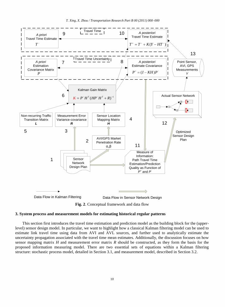
Fig. 2 illustrates the conceptual framework and data flow for the proposed modules. From sensor network
design plans in block 1, we need to extract three groups of critical input parameters: AVI/AVL market penetration
rates α and β at block 2, measurement error variance-covariance R in block 3, and sensor location mapping matrix H
in block 4. Location mapping matrix H is derived from the sensor location sets 'A , ''N and '''A .
The link travel time estimation module uses a Kalman filtering model to iteratively update the travel time
(blocks 9 and 10) and the corresponding error variance matrix (blocks 7 and 8), where the critical Kalman gain
matrix K, calculated in block 6, is applied to the above two mean and variance propagation processes. Based on the
estimation or prediction error variance statistics in blocks 7 and 8, the information quantification module derives the
measure of information in block 11 by representing the path travel time estimation/prediction quality as a function
of P+ and P
-. By minimizing the network-wide path travel time estimation uncertainty, the sensor network design
module finally selects and implements an optimized sensor plan so that point sensor, AVI, and AVL measurement
data in block 13 can be produced from the actual sensor network illustrated by block 12.
One of the key features offered by the Kalman Filtering model is that although updating the travel time mean
estimates from T in block 9 to T in
block 10 requires sensor measurements Y, the uncertainty propagation
calculation from block 7 to 8 (i.e. updating P from P ) does not rely on the actual sensor data, as the uncertainty
reduction formula in block 8 is a function of three major inputs: a priori uncertainty matrix P , measurement error
range R, and sensor mapping matrix H. In other words, if a transportation analyst can reasonably prepare the above
three input parameters, then he/she can apply the proposed analytical model to compute the information gain for a
sensor design scenario and further assist the decision-maker to determine where and with what technologies sensor
investments should be made in a traffic network.
T. Xing, X. Zhou / Transportation Research Part B 00 (2011) 000–000
10
4
Travel TimeA posteriori
Travel Time Estimate
( )T T K Y HT
A posteriori
Estimate Covariance
( )P I KH P
A priori
Travel Time Estimate
A priori
Estimation
Covariance Matrix
Sensor Location
Mapping Matrix
H
Measurement Error
Variance-covariance
R
Kalman Gain Matrix
1( )T TP H HP H RK
T
P
3
1
2
Actual Sensor Network
Sensor
Network
Design Plan
Data Flow in Kalman Filtering Data Flow in Sensor Network Design
AVI/GPS Market
Penetration Rate
α,β
Measure of
Information:
Path Travel Time
Estimation/Prediction
Quality as Function of
P+ and P
-
Point Sensor,
AVI, GPS
Measurements
Y
Optimized
Sensor Design
Plan
Non-recurring Traffic
Transition Matrix
L
Travel Time Uncertainty
13
11
8
10
7
9
6
2
3
1
12
5
Fig. 2. Conceptual framework and data flow
3. System process and measurement models for estimating historical regular patterns
This section first introduces the travel time estimation and prediction model as the building block for the (upper-
level) sensor design model. In particular, we want to highlight how a classical Kalman filtering model can be used to
estimate link travel time using data from AVI and AVL sources, and further used to analytically estimate the
uncertainty propagation associated with the travel time mean estimates. Additionally, the discussion focuses on how
sensor mapping matrix H and measurement error matrix R should be constructed, as they form the basis for the
proposed information measuring model. There are two essential sets of equations within a Kalman filtering
structure: stochastic process model, detailed in Section 3.1, and measurement model, described in Section 3.2.

T. Xing, X. Zhou / Transportation Research Part B 00 (2011) 000–000
11
3.1. Process model of day-varying traffic system under recurring conditions
In this study, link travel times are characterized as random variables through stochastic linear process models.
Two modeling approaches are available to capture travel time variations with different settings of time horizon and
resolution: within-day dynamic and day-to-day dynamic. Specifically, the within-day model estimates current travel
time based on the travel time at the previous time interval(s) on the same day, with a typical time resolution of 5 or
15 min. Without loss of generality, this study ignores the time-dependent travel time dimension in the estimation
equation below, and will discuss the time-dependent state transition equation in Section 4.
3.2. Measurement model
Shown in Eq. (2), a linear measurement model is used to map the measurement vector Yd to the travel time
vector Td (as state variables) by taking into account measurement error term εd from variant sources.
The following three equations show how Hd is constructed for a specific type of measurements on each day d. For a point sensor on link a,
, ,' ' , 'd a a d ay t a A . (5)
For a pair of point-to-point sensors that capture end-to-end travel time from node i to node j through path k,
, , , , , , , , ,'' '' , , ''d i j k i j k a a d i j k
a
y t i j N . (6)
For an AVL sensor/probe on link a,
, , ,''' ''' ''' , '''d a d a a d ay t a A .
(7)
A measurement in this model might be referred to an average value of multiple raw samples within a certain
time period (e.g. from 8:00 AM to 8:15AM). The error term in the above equations is a combined error term that
reflects the overall effect of errors from the data conversion, measurement reading and sampling processes.
Data conversion error: Typically, only time-mean speed data are available from a point sensor, and the travel
time value (i.e. space-mean speed) needs to be inferred and approximated from a point speed reading. This
introduces significant data conversion errors, depending on the placement of a point sensor on a link (e.g., the
relative location with respect to the tail of a queue from the downstream node of a link). In addition, a single-loop
detector has to use the observed occupancy and flow counts to calculate the point speed value, which leads to sensor
measurement errors. GPS location data (in terms of longitude, latitude, point speed, bearing and timestamps) need to
be map-matched to specific links in the study network to estimate corresponding link travel times. This map-
matching process again brings data conversion errors to the final link travel time estimates.
Sensor reading error: Point sensors that are not carefully calibrated are more likely to generate large
measurement noises. The detection rates of AVI readers are relatively low when vehicle tags are not powered by
batteries. The data quality of GPS location readings depends on the number of satellites that a GPS receiver can
“see”.
Sampling error: As a measurement can come from multiple readings, the variance of sampling error, e.g. for an
AVI measurement that is aggregated from , , ,''d i j kg samples, can be described as
, , ,
, , ,
, , ,
var( )var( '' )
''
d i j k
d i j k
d i j k
T
g
(8)
If we assume there is no correlation between link travel times along path k from node i to node j, then
, , , , ,
( , , ) ( , , )
var( ) var( )d i j k d a d a
a p i j k a p i j k
T T q
.
(9)
Assuming there are a total of , , ,d i j kf vehicles traveling from node i to node j through path k, then the AVI
market penetration rate α can be derived as , , , , , ,''d i j k d i j ka g f . That is, when the market penetration rate

T. Xing, X. Zhou / Transportation Research Part B 00 (2011) 000–000
12
increases, the size of samples also becomes larger, leading to a smaller sampling error and a more reliable travel
time measurement.
In summary, the magnitude of the combined error εd is determined by a number of external factors, and there are
also possible error correlations among different sensors depending on traffic conditions. For simplicity, the
following analysis assumes the combined errors belong to a white normal probability distribution with zero-mean
and a variance-covariance matrix R.
As point and AVL detectors are installed at fixed locations, the corresponding sensor mapping matrices, denoted
as 'dH and ''dH , typically remain the same within the study horizon, that is ' 'dH H and '' ''dH H . Even
with more accurate vehicle based link travel time samples, the AVL-based sensors still have two major limitations:
low market penetration rate and stochastic temporal coverage. Specifically, similar to the point-to-point AVI sensor,
a large sampling error is introduced to probe sensor measurements under a low market penetration rate, as shown by
, , ,var( ''' var( ) ''')d a d a d aT g , where ,'''d ag is the number of probe samples on link a on day d, and
,var( )d aT is
the systematic variance of link travel time on link a on day d. The same number of probe samples can generate
smaller measurement errors on a link with low travel time variability compared to a link with highly dynamic traffic.
Moreover, individual travelers with GPS probes can use different paths and links on different days, which leads to a
day-varying and stochastic sensor mapping matrix '''dH that consists of stochastic link traversing coefficient ,'''d a
for GPS probe vehicles.
3.3. Travel time estimation and prediction models
Given above process and measurement models, we are ready to derive a Kalman Filtering based estimation and
prediction model to update link travel times with different types of measurements.
In the following discussion, we need to distinguish two states of each day d: (1) a priori state before the start of
the current day (e.g. morning peak hour), corresponding to the predicted travel time dT and uncertainty
dP , and (2)
a posteriori state after the morning peak hour of current day, corresponding to estimated travel time dT and
uncertainty dP after taking into account new measurements dY
available on day d. We further define the a priori
estimate error dT as the difference between the true travel time vector Td and the a priori link travel time estimate
dT , where d d dT T T . The a posteriori estimate error
dT is the difference between the true travel time vector dT
and the a posteriori link travel time estimate dT . Define
d d dT T T , correspondingly, the variance-covariance
matrices of the a priori and a posteriori estimate error are expressed as T T[ ] [( )( ) ] cov( )d d d d d d d d dP E T T E T T T T T T (10)
T T[ ] [( )( ) ] cov( )d d d d d d d d dP E T T E T T T T T T (11)
3.3.1. Travel time estimate updating
In Kalman filtering, the a posteriori travel time estimate dT is updated through a linear function of the a priori
estimate dT and a weighted difference
d dY HT , which is the error of a priori estimate, otherwise known as the
innovation residual or measurement residual.
( )d d d dT T K Y HT (12)
3.3.2. Kalman gain factor calculation and uncertainty propagation
By assuming the measurement error covariance Rd is uncorrelated to Kd and Yd, a general formulation for the
variance-covariance matrix of the a posteriori estimate error can be derived (see appendix for equation derivation). T T( ) ( )d d d d d d dP I K H P I K H K RK
(13)
The above equation shows the propagation of the estimation error covariance for any given matrix Kd. In Eqs.
(12) and (13), matrix Kd is used as the gain factor to update the a posteriori estimation dT and its error covariance

T. Xing, X. Zhou / Transportation Research Part B 00 (2011) 000–000
13
dP . In Kalman filtering, Kd is determined by minimizing the trace of a posteriori estimate error matrix, which is
setting the first derivative of Eq. (13) to 0 as follows:
TT
trace2 2 0
d
d d d d d d d
d
PH P K H P H R
K
(14)
The optimal form of Kd is then derived as T T 1( )d d d d d dK P H H P H R
(15)
Under the optimal formulation of the Kalman gain matrix in Eq. (15), a simplified expression for the estimation
error covariance is derived as
( )d d dP I K H P (16)
Other formulas of the estimation error covariance are available, for example,
1
1 1( ) Td d
P P H R H
(17)
a b1 H=1
Fig. 3. Single-link example
Consider a single link shown in Fig. 3 where a link from a to b corresponding to sensor mapping matrix H = 1.
In the historical travel time database, the estimated travel time follows a normal distribution with a mean of 15 min
and a standard deviation of 5 min (i.e . 25dP ). Given a new measurement 20dY min with a measurement
error variance of 5 min, based on Eq. (15), we can calculate the optimal Kalman filtering gain factor as
25 (25 5) 5 / 6dK . Then the travel time estimate is updated by Eq. (12), calculated as
15 (5 / 6)(20 15) 19.6d
T , and the posterior estimation variance is reduced to 1 (5 / 6) 25 1.8
dP
.
The calculation results are summarized in Table 1.
Table 1
Calculation results of single-link example
Prior estimate Measurement Posterior estimate
Travel time (min) 15dT
20dY
19.6dT
Variance (min2) 25dP
5dR
1.8dP
3.3.3. Travel time prediction
After updating travel time mean estimate and its covariance on day d, we now need to predict travel time and its
uncertainty range for the same time interval of the next day, d+1. According to the system process equation (1), the
mean estimate can be simply extended across days under recurring traffic conditions.
1d dT T
(18)
However, by taking into account the unpredicted random realizations of traffic demand and capacity,
characterized by the system error matrix dQ , we have to increase the uncertainty estimate for 1dT
+1d d dP P Q (19)
With the above measurement updating equations (12-17) and prediction equations (18-19), the Kalman filtering
based travel time estimation and prediction model is able to recursively correct the link travel time estimate from
streaming traffic measurements and dynamically adjust the error covariance matrix that indicates the uncertainty
range of the prediction results.

T. Xing, X. Zhou / Transportation Research Part B 00 (2011) 000–000
14
4. Travel time prediction under non-recurring conditions
Under non-recurring congestion conditions, the structural deviation ( )d
V t is considered under various
demand/capacity changes. The process equation of the structural deviation in real-time prediction applications can
be written as a state space model:
( ) ( , ) ( ) ( ), ( ) (0, )NR
d d d d d dV t h L t t h V t t h t h N Q (20)
In Eq. (20), the transition matrix L denotes the process matrix of the structure derivation. The process error d
is
considered as a normally distributed random noise. Following we will discuss the non-recurring traffic estimation
and prediction with and without sensor coverage, and present two case studies taking incident as a demonstration
example.
4.1. Traffic estimation and prediction equations
For links with sensor coverage, a measurement d
Y is obtained for each time interval. Similar to the derivation
for the regular pattern traffic, the estimation equations for the non-recurring structural deviation and its uncertainty
are
( ) ( ) ( ( ) ( ) ( ) ( ) ( ))h
d d NR d d d dV t V t K Y t H t T t H t V t (21)
1
1 1( ) ( ) ( )T
d d d dH t R H t
(22)
The Kalman gain factor KNR can be derived similar to the recurring traffic model.
The prediction equations for the structural deviation and its uncertainty are
( ) ( , ) ( )d d dV t h L t t h V t (23)
( ) ( , ) ( ) ( , )T NR
d d d d dt h L t t h t L t t h Q (24)
With the derivation of the structural deviation, the predicted travel time variance under non-recurring conditions
is represented as
1
1
( ) ( ) ( )
( ) ( , ) ( ) ( , )
d d d d
T NR
d d d d d d
P t h P t h t h Q
P t h Q L t t h t L t t h Q
(25)
Eq. (25) computes the prediction uncertainty at time (t+h). By comparing to the regular pattern uncertainty
prediction in Eq. (19), we noticed that the uncertainty of non-recurring conditions is considered as a linear
combination of the regular pattern and the structural deviation.
For links without sensor coverage, no measurement is available of the estimation for the structure derivation d
V .
Therefore, predicted values for both structure derivation ( )d
V t and link travel time ( )
dT t will be biased, and an extra
error has to be considered into the system uncertainty estimation and prediction. In this study we use the maximum
dV across all links with sensors from the historical database as a way to estimate the potential bias magnitude on
links without sensors. As a result, the corresponding elements in the prior structure derivation uncertainty matrix have large values for links without sensor coverage, and relatively small values for links equipped with sensors.
4.2. Single bottleneck model with incident
We now shift our focus on how to compute the essential transition matrix ( , )d
L t t h , with a single bottleneck
case study. Newell’s kinematic wave model (Newell, 1993) is used in this research to capture forward and backward
waves as results of bottleneck capacities. Its simplified form of traffic flow models is particularly attractive in

T. Xing, X. Zhou / Transportation Research Part B 00 (2011) 000–000
15
establishing theoretically sound and practically operational traffic transition models on bottlenecks. Interested
readers are referred to a number of related studies on Newell’s kinematic wave model, e.g. the model calibration
effort by Hurdle and Son (2000), extensions to node merge and diverge cases by Yperman et al. (2005) and Ni et al.
(2006).
Cu
mu
lati
ve F
low
Cou
nt
Incident
Duration
Time
C
e
C
s
Additional Delay V(t)
Arrival Curve A
Departure Curve D
with Incident
Original Departure
Curve D’
Reduced Capacity
CR
t t + h
t t + h
t t + h
Fig. 4. Cumulative flow count curve for a single bottleneck with reduced capacity due to an incident
Considering Fig. 4, a recurring congestion is assumed with a constant queue discharging rate C. An incident
under consideration begins at time s and ends at time e with a reduced capacity CR
, and this capacity is restored
back to C after time e. In order to derive the transition matrix L for updating the structural deviation V(t), we further
examine the additional delay in a detailed plot.
Shown in Fig. 5, V(t) = t – t', where t' is the original leaving time from the queue under recurring congestion for
the same vehicle. Δ is denoted as the number of vehicles can be discharged under recurring congestion from s to t',
and we can derive ( ' ) ( )R
C t s C t s . That is, ' / ( / )( )R
t s C C C t s . Thus, the travel time
structure deviation term can be determined as
( ) ( ) ( ' ) ( ) 1RC
V t t s t s t sC
.
(26)
After the incident ending time e, V(t) becomes a constant value 1RC
e sC
.
CR
C
V(t)
Δ
ts t'
TimeCu
mu
lati
ve
Flo
w C
ou
nt
Fig. 5. A zoom-in view on capacity reduction

T. Xing, X. Zhou / Transportation Research Part B 00 (2011) 000–000
16
We can further examine the transition matrix L in three cases (as shown in Fig. 4), with a pre-defined prediction
period h (e.g. 15 min). According to the prediction equation (23) for the structure derivation, the transition matrix L
(a single value in this example) is derived as the ratio of structure deviation terms between current time t and future
time t+h.
( )( , )
( )
V t hL t t h
V t
(27)
Table 2 Derivation of transition matrix L for different time periods
Scenarios t t+h V(t) V(t+h) L(t,t+h)
Early
Detection s < t < e-h s+h < t+h < e ( ) 1
RCt s
C
( ) 1
RCt h s
C
t h s
t s
Late
Detection e-h < t < e t+h > e ( ) 1
RCt s
C
1
RCe s
C
e s
t s
Post-incident
Detection t > e t+h > e+h 1
RCe s
C
1
RCe s
C
1
As shown in Table 2, with the prediction time stamp t is located in different time periods, the transition matrix L
is derived in different forms. Fig. 6 gives an illustrative example on how the transition coefficient L varies according
to time t, by assuming the prediction period h = 15 min and a typical incident duration e – s = 30 min.
Fig. 6. Illustration of time-dependent transition coefficient L
The above example demonstrates how to derive the transition matrix L under non-recurring conditions with
short-term capacity drops. Similar matrices could be derived for severe weather and work zone cases. Obviously,
L(t,t+h) is a time-dependent and situation-dependent variable that needs to determine in a case-by-case basis in real-
world travel time prediction applications. For the sensor location problem under consideration, we need to assume
and use an aggregated transition matrix for simplicity. In our experiments for the sensor location problem, we
consider the following typical case: average incident duration = (e-s) = 30 min, incident reporting period = (t-s) = 15
min, and this leads to a typical value L = 2 which will be used in the experiments in Section 8.
5. Measure of information for historical traffic patterns
s 10 20 e 400
1
2
3
4
Time after incident (min)
Tra
nsi
tio
n c
oef
fici
ent
L

T. Xing, X. Zhou / Transportation Research Part B 00 (2011) 000–000
17
One of the fundamental questions in sensor location problems is which criteria should be selected to drive the
underlying optimization processes. Eqs. (13-17 & 19) in the above travel time estimation and prediction model offer
an analytical model for quantifying the estimation/prediction error reduction due to additional measurements
provided by new sensors. As the process variance-covariance matrix is assumed to be constant, the travel time
uncertainty measure in this section uses the a posterior estimation error covariance P+ as the basis to evaluate the
information gain. A challenging question then is how to select single-value information measures for a sensor design
plan. To this end, we first examine two commonly used estimation criteria, namely, the mean-square error and
entropy. We then propose total path travel time estimation variance as a new measure of information for end-to-end
trip time prediction applications.
5.1. Trace and entropy
As shown in Eq. (14), when selecting the gain factor K to utilize new measurements, the classic Kalman filter
aims to minimize the mean-square error, i.e., the trace of dP . The trace of the variance covariance matrix dtr P
is the sum of the diagonals of the matrix, which is equivalent to the total variance of link travel time estimates for all
links:
, , ,
1 1
cov( , ) var( )m m
d d a d a d a
a a
tr P t t t
(28)
While the trace does not consider the effects of correlation between travel times of adjacent links, an alternative
measure of information is entropy which is commonly used in information theory applications. For a discrete
variable, Shannon’s original entropy is defined as the number of ways in which the solution could have arisen. For a
continuously distributed random vector T, on the other hand, the entropy is measured by (ln ( ))E f T , where f is
the joint density function for vector T. If travel time T in our study is assumed to follow a normal distribution, then
its entropy is computed as 1
ln(det( ))2
dP
, where θ is a constant that depends on the size of T, the total number of
links in our study network. The entropy measure is proportional to the log of the determinant of the covariance
matrix. By ignoring the constant θ and the monotonic logarithm function, we can simplify the entropy-based
information measure for the a posteriori travel time estimate as det( )d
P
. The determinant of the variance
covariance matrix, as a measure of information, is also known as the generalized variance. Mathematically, the trace
and determinant of the variance covariance matrix dP can be calculated from the sum and product, respectively, of
the eigenvalues of dP . Since the determinant considers the variance and covariance in the matrix, a smaller
determinant is desirable because this indicates a more accurate estimate.
5.2. Total path travel time estimation uncertainty
This study proposes a new measure of information to quantify the network-wide value of information, based on
the travel time estimation quality of critical OD/paths.
The travel time estimation uncertainty of path k from origin o to destination s can be calculated from the
posterior travel time estimate variance-covariance matrix dP :
, , , , , ,
( , , ) ; , ( , , )
var( ) 2 cov( , )d o s k d a d a d b
a p o s k a b a b p o s k
e t t t
,
(29)
where var() and cov() are variance and covariance coefficients in the link travel time uncertainty matrix,
respectively. Compared to trace or entropy based information measures, the proposed path travel time based
measure can better capture the possible correlation between traffic estimates along a path, with the covariance
portion of the estimation error matrix.
T. Xing, X. Zhou / Transportation Research Part B 00 (2011) 000–000
18
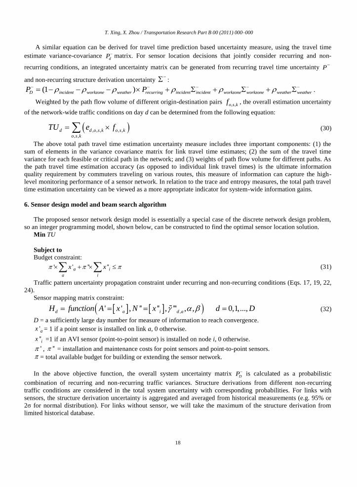
A similar equation can be derived for travel time prediction based uncertainty measure, using the travel time
estimate variance-covariance dP matrix. For sensor location decisions that jointly consider recurring and non-
recurring conditions, an integrated uncertainty matrix can be generated from recurring travel time uncertainty P
and non-recurring structure derivation uncertainty :
(1 )D incident workzone weather recurring incident incident workzone workzone weather weatherP P .
Weighted by the path flow volume of different origin-destination pairs , ,o s kf , the overall estimation uncertainty
of the network-wide traffic conditions on day d can be determined from the following equation:
, , , , ,
, ,
d d o s k o s k
o s k
TU e f
(30)
The above total path travel time estimation uncertainty measure includes three important components: (1) the
sum of elements in the variance covariance matrix for link travel time estimates; (2) the sum of the travel time
variance for each feasible or critical path in the network; and (3) weights of path flow volume for different paths. As
the path travel time estimation accuracy (as opposed to individual link travel times) is the ultimate information
quality requirement by commuters traveling on various routes, this measure of information can capture the high-
level monitoring performance of a sensor network. In relation to the trace and entropy measures, the total path travel
time estimation uncertainty can be viewed as a more appropriate indicator for system-wide information gains.
6. Sensor design model and beam search algorithm
The proposed sensor network design model is essentially a special case of the discrete network design problem,
so an integer programming model, shown below, can be constructed to find the optimal sensor location solution.
Min TU
Subject to
Budget constraint:
' ' '' ''a i
a i
x x (31)
Traffic pattern uncertainty propagation constraint under recurring and non-recurring conditions (Eqs. 17, 19, 22,
24).
Sensor mapping matrix constraint:
,' ' , '' '' , ''' , , 0,1,...,d a i d aH function A x N x d D
(32)
D = a sufficiently large day number for measure of information to reach convergence.
'ax = 1 if a point sensor is installed on link a, 0 otherwise.
''ix =1 if an AVI sensor (point-to-point sensor) is installed on node i, 0 otherwise.
' , '' = installation and maintenance costs for point sensors and point-to-point sensors.
= total available budget for building or extending the sensor network.
In the above objective function, the overall system uncertainty matrix DP is calculated as a probabilistic
combination of recurring and non-recurring traffic variances. Structure derivations from different non-recurring
traffic conditions are considered in the total system uncertainty with corresponding probabilities. For links with
sensors, the structure derivation uncertainty is aggregated and averaged from historical measurements (e.g. 95% or
2σ for normal distribution). For links without sensor, we will take the maximum of the structure derivation from
limited historical database.

T. Xing, X. Zhou / Transportation Research Part B 00 (2011) 000–000
19
dH is determined by the sensor location set ' 'aA x and '' ''iN x , randomly generated link traversing
coefficient for GPS probe vehicles ,
'''d a
, and AVI and AVL market penetration rates α and β.
Essentially, the goal of the above sensor location model is to add sensor information from spatially distributed
measurements to minimize the weighted uncertainty associated with the path travel time estimates. In this study, a
branch-and-bound search procedure can be used to solve the integer programming problem. To reduce the
computational complexity, a beam search heuristic algorithm is implemented in this study.
Given prior information on the link travel time vector and its estimation error covariance from historical
database, the proposed algorithm tries to find the best sensor location scenario from a set of candidates under
particular budget constraints. Based on a breadth-first node selection mechanism, the beam search algorithm
branches from the nodes level by level. At each level, it keeps only φ promising nodes, and prunes the other nodes
permanently to limit the total number of nodes to be examined. φ is typically referred to as the beam width, and the
total computational time of the beam search algorithm is proportional to the selected beam width.
Beam search algorithm
Step 1: Initialization
Generate candidate link set LC and candidate node set NC for point and point-to-point sensors, respectively.
Set the active node list ANL . Create the root node u with '( ) , "( )A u N u , search level
( ) 0sl u , where u is search node index. Insert the root node into ANL.
Step 2: Stopping criterion
Terminate and output the best-feasible solution under one of the following conditions:
(1) If all of the active nodes in ANL have been visited,
(2) The number of active nodes in memory is exceeded.
Step 3: Node generation and evaluation
For each node u at search level sl in ANL, remove it from ANL, and generate child nodes;
Scan through the candidate sets LC, if a link a is not in A'(u), generate a new child node v’ where
'( ') '( ) , "( ') "( ), ( ') ( ) 1A v A u a N v N u sl v sl u ;
Scan through the candidate sets NC, if a node i is not in N''(u), generate a new child node v” where
"( ") "( ) , '( ") '( ), ( ") ( ) 1N v N u i A v A u sl v sl u ;
For each newly generated node v, calculate the objective function through DP
in Eq. (30). If the budget
constraint is satisfied for a newly generated node, add it into the ANL.
Step 4: Node filtering
Select φ best nodes from the ANL in the search tree, and go back to Step 2.
In the above beam search algorithm, the total computational time is determined by the number of nodes to be
evaluated, which depends on the beam width φ and the size of the candidate sensor links/nodes. For each node in the
tree search process, the complexity is determined by the evaluation of the objective function, which can be
decomposed into three major steps: (1) calculating P from 1TH R H , (2) calculating the inverse of the covariance
matrix 1( )P , and (3) calculating the path travel time uncertainty as a function of DP . The first step involves two
matrix multiplications: 1TH R and 1( )TH R H . Because H is an (nm) matrix and R is an (nn) matrix, the first
step has a worst-case complexity of O(m2n), and calculating the inverse of matrix leads to an O(m
3) operation if the
Gaussian elimination method is used.
For a large-scale sensor network design application, we can adopt three strategies to reduce the size of the
problem and therefore the computational time. First, one can focus on critical OD pairs with significant volumes.
Second, one can aggregate original OD demand zones into a set of super zones within a manageable size, with this
strategy being especially suitable for a subarea analysis where many OD zones outside the study area can be
consolidated together. Third, we can reduce the size of candidate AVL sensor nodes and point sensor links in order
to decrease the number of search nodes to be evaluated.

T. Xing, X. Zhou / Transportation Research Part B 00 (2011) 000–000
20
7. Complex cases for updating historical traffic patterns
7.1. Quantifying steady state information gain
To consider long-term information gains of a sensor network in monitoring the travel time dynamics, the
following discussion aims to derive the steady-state results of uncertainty reduction associated with a fixed sensor
network design plan. Considering both point and AVL sensors, we first assume constant Q, R and H across different
days, the travel time estimation error covariance updating equation as seen in Eq. (33), which was combined from
Eqs. (16) and (19),
1 1( )d d dP I K H P Q
(33)
Under steady state conditions, the travel time estimation error covariance will achieve a constant state as
1d dP P P
after a number of updates. By applying the optimal formulation of Kalman gain K in Eq. (15), the
steady estimation error covariance P is rewritten as 1( )T TPH HPH R HP Q (34)
or 1( ( ) )T TP I PH HPH R H P Q (35)
Eq. (35) is known as Algebraic Riccati Equation. When numerically solving this equation, the steady-state
travel time estimation error covariance matrix for a long-term sensor location problem is obtained.
Fig. 7. Steady-state travel time estimation variance
Fig. 7 illustrates a day-by-day time series of the travel time estimation variance. Due to the presence of system
evolution noise Q, the estimation variance always increases when we make a travel time prediction from day d to
day d+1, that is, d d dP P Q . After receiving traffic measurement available every day, the uncertainty associated
travel time estimates is reduced through ( )d d d
P I K H P . The uncertainty reduction and the resulting
information gain are very dramatic after the first few days of sensor deployment. After 5 or 6 days, this zig-zag
pattern reaches a stable state when 1d dP P
(corresponding to the upper portion of the time series) and
1d dP P
(corresponding to the lower portion of the time series).
Due to the stochastic coverage characteristic of AVL sensor data, we can use a sample-based iterative
computation scheme to compute the stable-state posterior estimation covariance matrix P+. In particular,
representative samples of ,'''d a can be first generated for each day, and then applied into the update equations (16)
and (19) over multiple days to check if det(P+) converges to a constant value .
0
1
2
3
4
5
6
7
0 1 2 3 4 5 6 7 8 9 10 11 12 13
Tra
vel
Tim
e E
stim
atio
n
Var
iance
Pd
Day d
dP
dP

T. Xing, X. Zhou / Transportation Research Part B 00 (2011) 000–000
21
7.2. AVI extension with multiple paths
In the previous discussions, we assume that all AVI-equipped travelers use only a single path between each pair
of AVI sensors. In the following discussion, we shift our focus from a single path case to a more complex but
realistic situation with multiple used paths between a pair of AVI sensors. For simplicity, we assume the route
choice probabilities for those paths can be computed from a deterministic or stochastic traffic assignment program.
This study adapts a multivariate normal (MVN) distribution to represent the route choice behavior. In particular,
each route choice decision from an individual traveler can be considered as an independent Bernoulli trial from one
of the K possible outcomes (i.e. paths) with probabilities p1, …, pk,…, pK.
a b c3
AVI readernode
1
2
Fig. 8. Two partially overlapping path between AVI readers at nodes a and c
Consider an example network shown in Fig. 8, where two AVI sensors are located at nodes a and c. Travelers
can take either of two routes through link sequence: (path k = 1)13 or (path k = 2) 23, where link 3 is shared by
these two paths. We now extend AVI measurement equation (6) from a single path to the following with two paths
(subscripts d, i,j are omitted for notation simplicity).
1
1 2 2 1 1 2 2 3
3
'' '' '' 1
t
y H T p p t p t p t t
t
(36)
where p1 and p2 represent the route choice probability for link 1 and 2, with 1 2 1p p ,
''y is the average travel time from travelers using two routes, the contribution from travelers using route 1 is
1 1 3( )p t t and the contribution from route 2 is 2 1 3( )p t t ,
is the error term introduced by sampling variations due to multiple paths,
is the error term associated with using the sample average value to approximate the population mean value T,
as described in Eq. (8).
The variance of multi-choice sampling variation can be calculated by
2 2
1 1 2 2 3 1 1 2 2 1 2 1 2var( ) var( ) var( ) var( ) 2 cov( , )p t p t t t p t p t t p p (37)
Assuming there are g AVI samples observed between this AVI sensor pair, and xk use path k, we can derive
E( ) E( )k k k
p x g p , 2var( ) var( ) (1 )
k k k kp x g p p g , and cov( , )k kh h p p g .
Thus, Eq. (37) is reduced to
2 1 2
2 1var( ) ( )p p
t tg
(38)
First, it is clear that the overlapping portion, link 3, does not affect the variance associated with the multi-choice
sampling error. Under perfect deterministic user equilibrium conditions, all of the used routes have the same travel
time, so the var( ) further reduces to zero. Under a more realistic stochastic user equilibrium assumption, the travel
time difference between different used routes will increase the range of the combined error var( '') var( )R .

T. Xing, X. Zhou / Transportation Research Part B 00 (2011) 000–000
22
We can further extend the 2-path case to consider multiple paths on a corridor with K parallel non-overlapping
routes, shown in Fig. 9. In general, the variance of the combined error increases as there are more used paths with
significant travel time differences.
2
1 1
, ,
1var( ) var( ... ) ( )k k K K k k
k k
p t p t p t t t p pg
(39)
a b2
AVI readernode
1
3
Fig. 9. Example network with three parallel paths
8. Illustrative example and numerical experiments
8.1. Illustrative example for locating AVI sensors
In Fig. 10, we present an illustrative example with a 6-node hypothetical transportation network to demonstrate
how the proposed measures of information can systematically evaluate the trade-offs between the accuracy and
placement of individual AVI sensors for path travel time estimation reliability. In Fig. 10, subscript day d is omitted
for simplicity. As shown in the base case, there are three traffic analysis zones at nodes a, d and b, and three major
origin-to-destination trips: (1) a to b, (2) a to d and (3) d to b, each with a unit of flow volume. P
(e.g. obtainable
from a historical travel time database with point detectors) leads to a trace of 12 and a determinant of 48. Among the
5 links in the corridor, link 5 from node f to b has the highest uncertainty in terms of link travel time estimation
variance. We can view node b as a downtown area, and the incoming flow from the other two zones creates dramatic
traffic congestion and travel time uncertainty, first on link 5 and then on link 4. For the base case, we can calculate
the variance of path travel time estimates for these three OD pairs, respectively, as 12, 3 and 9, leading to a total
path travel time estimation uncertainty (TU) as TU = 24.

T. Xing, X. Zhou / Transportation Research Part B 00 (2011) 000–000
23
AVI readernode
c d e f1 2 53 4
a bc d e f1 2 53 4
a bc d e f1 2 53 4
Base case
(I) Locate additional AVI reader to reduce highest link travel time uncertainty
(II) Locate additional AVI reader to match origin-to-destination trip pairs
1 0 0 0 0
0 2 0 0 0
12 48 12 3 9 240 0 2 0 0
0 0 0 3 0
0 0 0 0 4
P Tr Det TU
-1
1 0
0 1
1 1 1 1 0 0.89 0.22 0.22 0.33 0
1 1 1 1 0 0.22 1.56 0.44 0.67 0
1 1 1 1 0 0.22 0.44 1.56 0.67 0
1 1 1 1 0 0.33 0.67 0.67 2 0
0 0 0 0 1 0 0 0 0 0.8
6.8 1.07 3.4
T
R
H R H P
Tr Det TU
7 2.01 3.02 8.5
-1
1 0 1 1 0 0 0
0 1 0 0 1 1 1
1 1 0 0 0 0.75 0.5 0 0 0
1 1 0 0 0 0.5 1 0 0 0
0 0 1 1 1 0 0 1.6 0.6 0.8
0 0 1 1 1 0 0 0.6 2.1 1.2
0 0 1 1 1 0 0 0.8 1.2 2.4
7.85 1.2 1.65 0.75
T
R H
H R H P
Tr Det TU
0.9 3.3
fk=2 =1
fk=1 =1
fk=3 =1
Link 1 2 3 4 5
1 1 1 1 0
0 0 0 0 1H
Measurement
a->d
d->b
Link 1 2 3 4 5
Measurement
a->f
f->b
ba
Fig. 10. Example of locating AVI sensors on a linear corridor
T. Xing, X. Zhou / Transportation Research Part B 00 (2011) 000–000
24
In both cases (I) and (II), two AVI sensors are first installed at nodes a and b. In case (I), an additional AVI
sensor is located at node f so that we can obtain two pairs of end-to-end travel time measurements: from node a to
node f, and from node f to node d. The second measurement directly monitors travel time dynamics on link 5. In this
particular example along the linear corridor, the end-to-end travel time statistics from a to b can be explicitly
determined from the above two mutually exclusive observations. In order to avoid double-counting the information
gain for the same data sources, the information quantification module in this study only considers two raw
measurements: from a to f, and from f to d, to update the link travel time variance covariance matrix from P to
P. To do so, the measurement error matrix is assumed to be
1 0
0 1R
, and the mapping matrix
1 1 1 1 0
0 0 0 0 1H
, where the first measurement from a to f covers links 1,2,3 and 4, and the second
measurement from f to b covers link 5. As link 5, with the highest travel time uncertainty, is directly measured from
AVI readings, its link travel time estimate variance is reduced from 4 to 0.8, but the resulting P contains a large
amount of correlation in its link travel time estimates for links 1 to 4. All the path travel time uncertainties for the
three OD pairs have been reduced, and TU = 8.5.
In case (II), the third AVI sensor is installed at node d to match the nature OD trip demand pattern, which
produces sensor mapping matrix1 1 0 0 0
0 0 1 1 1
H
. The resulting P still contains two clusters of
correlations corresponding to two individual measurements from a to d and from d to b. The path travel time
estimate variances for the OD pairs from a to d and from d to b are dramatically reduced to 0.75 and 0.9. Although
link 5 still has a relatively large estimate variance of 2.4, its overall estimation error measure, total travel time
estimation uncertainty TU is now 3.3, which is much lower than TU = 8.5 in case (I).
In comparison, by locating and spacing AVI sensors to naturally match the spatial trip patterns of commuters,
case (II) is able to systematically balance the trade-off between the needs for monitoring local traffic variations and
end-to-end trip time dynamics. It is also important to notice that, both cases (I) and (II) have the same network
coverage and generate the same number of measurements every day, but they provide different information gains
from a commuter/road user perspective. Thus, simple measures of information, such as traffic network coverage and
the number of measurements, might not be able to quantify the system-wide uncertainty reduction and information
gain for traveler information provision applications.
8.2. Sensor location design for traffic estimation with recurring conditions
In this study, we examine the performance of the proposed modeling approach through a set of experiments on a
simplified Irvine, California network, which is comprised of 16 zones, 31 nodes and 80 directed link. This study
considers a single path between each OD pair in this simple network.
All the experiments are performed on a computer system equipped with an Intel Core Duo 1.8GHz CPU and 2
GB memory. Shown in Table 3, a set of critical OD pairs with large flow is selected to estimate the network-wide
path travel time based uncertainty. Additionally, a beam search width of 10 is used in the beam search algorithm to
reduce the computational complexity. The total number of nodes in the search tree is the number of additional
sensors times the beam search width. In our experiments, with standard Matlab matrix calculation functions, it takes
about 30 min to compute 160 nodes in the beam search tree for this small-scale network.
In this section, we examine the proposed information measure model and sensor location algorithm for the
estimation of recurring traffic conditions. With given OD flow and prior uncertainty information, three scenarios of
sensor location plan are designed to compare with current sensor network.

T. Xing, X. Zhou / Transportation Research Part B 00 (2011) 000–000
25
We first conduct experiments to compare the existing point sensor network (Fig. 11a) and an optimized point
sensor network plan (Fig. 11b), both with the same number (i.e. 16) of point sensors. Table 3 shows the critical path
travel time estimation errors under those two scenarios. The results show that the proposed optimization model can
reduce the path travel time estimation variance by an average of 34.3%, while the existing sensor plan only reduces
the same measure by about 16.5%. By factoring in the OD demand volume (shown in the third column), we can
compute the proposed measure of information: the total path travel time estimation variance. The base case with
zero sensor produces TU_zero_sensor=114855, the existing locations reduce TU to 88878 (77.3% of
TU_zero_sensor), and the optimized sensor location scenario using the proposed model further decreases the
system-wide uncertain to TU= 63586 (55.3% of TU_zero_sensor). This clearly demonstrates the advantage of the
proposed model in terms of improving end-to-end travel time estimation accuracy.
1
2
3
4
5
6
7
8
9
10
12
11
13
14 15
16
Existing loop detector
Demand zone
(a) Existing point sensor locations
1
2
3
4
5
6
7
8
9
10
12
11
13
14 15
16
(b) Optimized sensor network locations
(start from a zero-sensor case)
Optimized point sensor location
Demand zone
1
2
3
4
5
6
7
8
9
10
12
11
13
14 15
16
Existing loop detector
Demand zone
Additional loop detector
(c) Sensor network with 4 point sensors in
addition to exiting 16 point sensors
1
2
3
4
5
6
7
8
9
10
12
11
13
14 15
16
Existing loop detector
Demand zone
Additional AVI sensor
(d) Sensor network with 6 AVI sensors in
addition to exiting 16 point sensors
Fig. 11. Numerical experiment results for regular traffic pattern estimation.
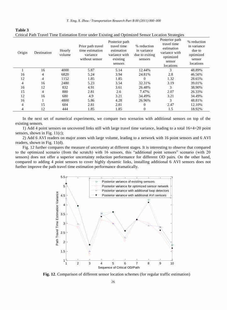
T. Xing, X. Zhou / Transportation Research Part B 00 (2011) 000–000
26
Table 3
Critical Path Travel Time Estimation Error under Existing and Optimized Sensor Location Strategies
Origin Destination Hourly
volume
Prior path travel
time estimation
variance
without sensor
Posterior path
travel time
estimation
variance with
existing
sensors
% reduction
in variance
due to exiting
sensors
Posterior path
travel time
estimation
variance with
optimized
sensor
locations
% reduction
in variance
due to
optimized
sensor
locations
1 16 4000 5.87 5.14 12.44% 3 48.89%
16 4 6820 5.24 3.94 24.81% 2.8 46.56%
12 4 1152 1.85 1.85 0 1.32 28.65%
4 16 2480 5.23 3.54 32.31% 3.19 39.01%
16 12 832 4.91 3.61 26.48% 3 38.90%
15 4 880 2.81 2.6 7.47% 2.07 26.33%
12 16 680 4.9 3.21 34.49% 3.21 34.49%
16 1 4800 5.86 4.28 26.96% 3 48.81%
4 15 604 2.81 2.81 0 2.47 12.10%
4 12 444 1.85 1.85 0 1.5 18.92%
In the next set of numerical experiments, we compare two scenarios with additional sensors on top of the
existing sensors.
1) Add 4 point sensors on uncovered links still with large travel time variance, leading to a total 16+4=20 point
sensors, shown in Fig. 11(c);
2) Add 6 AVI readers on major zones with large volume, leading to a network with 16 point sensors and 6 AVI
readers, shown in Fig. 11(d).
Fig. 12 further compares the measure of uncertainty at different stages. It is interesting to observe that compared
to the optimized scenario (from the scratch) with 16 sensors, this “additional point sensors” scenario (with 20
sensors) does not offer a superior uncertainty reduction performance for different OD pairs. On the other hand,
compared to adding 4 point sensors to cover highly dynamic links, installing additional 6 AVI sensors does not
further improve the path travel time estimation performance dramatically.
Fig. 12. Comparison of different sensor location schemes (for regular traffic estimation)
1 2 3 4 5 6 7 8 9 101
1.5
2
2.5
3
3.5
4
4.5
5
5.5
Sequence of Critical OD/Path
Path
Tra
vel T
ime E
stim
ation V
ariance
Posterior variance of existing sensors
Posterior variance for optimized sensor network
Posterior variance with additional loop detectors
Posterior variance with additional AVI sensors

T. Xing, X. Zhou / Transportation Research Part B 00 (2011) 000–000
27
8.3. Sensor location design for traffic prediction with recurring and non-recurring conditions
Now we perform the proposed algorithm by considering both regular and non-recurring traffic conditions. As
discussed in Section 7, the total traffic prediction uncertainty is computed as a probabilistic combination of recurring
and non-recurring uncertainties. In this numerical experiment, we take the incident as a demonstration example, with
the link based incident rates shown in Fig. 13(a). The proposed sensor location algorithm is applied in three
scenarios: (1) optimized sensor network with 16 point sensors, (2) current network with additional 4 point sensors,
and (3) current network with additional 6 AVI sensors. Consequentially, these three sensor network design results
are plotted in Figs. 13(b-d). It is interesting to note that when considering non-recurring traffic conditions
(incidents), the optimized sensor locations (Fig. 13b) are more focused on links with higher incident rates, compared
to the regular pattern estimation based planning result in Fig. 11(b).
(a) Annual incident rate
1
2
3
4
5
6
7
8
9
10
12
11
13
14 15
16
Annual incidents per mile
Demand zone
50
100
150
200
300
(b) Optimized sensor network locations
(start from a zero-sensor case)
1
2
3
4
5
6
7
8
9
10
12
11
13
14 15
16
Optimized point sensor location
Demand zone
1
2
3
4
5
6
7
8
9
10
12
11
13
14 15
16
Existing loop detector
Demand zone
Additional loop detector
(c) Sensor network with 4 point sensors in
addition to exiting 16 point sensors
1
2
3
4
5
6
7
8
9
10
12
11
13
14 15
16
Existing loop detector
Demand zone
Additional AVI sensor
(d) Sensor network with 6 AVI sensors in
addition to exiting 16 point sensors
Fig. 13. Numerical experiment results under recurring and non-recurring traffic conditions

T. Xing, X. Zhou / Transportation Research Part B 00 (2011) 000–000
28
9. Conclusions
To provide effective congestion mitigation strategies, transportation engineers and planners need to
systematically measure and identify both recurring and non-recurring traffic patterns through a network of sensors.
The collected data are further processed and disseminated for travelers to make smart route and departure decisions.
There are a variety of traditional and emerging traffic monitoring techniques, each with ability to collect real-time
traffic data in different spatial and temporal resolutions. This study proposes a theoretical framework for the
heterogeneous sensor network design problem. In particular, we focus on how to better construct network-wide
historical travel time databases, which need to characterize both mean and estimation uncertainty of end-to-end path
travel time in a regional network.
A unified Kalman filtering based travel time estimation and prediction model is first proposed in this research to
integrate heterogeneous data sources through different measurement mapping matrices. Specifically, the travel time
estimation model starts with the historical travel time database as prior estimates. Point-to-point sensor data and
GPS probe data are mapped to a sequence of link travel times along the most likely travelled path. Through an
analytical information updating equation derived from Kalman filtering, the variances of travel times on different
links are estimated for possible sensor design solutions with different degree of sampling or measurement
errors. The variance of travel time estimates for spatially distributed links are further assembled to calculate the
overall path travel time estimation uncertainty for the entire network as the single-valued information measure. The
proposed information quantification model and beam search solution algorithm can assist decision-makers to select
and integrate different types of sensors, as well as to determine how, when, where to integrate them in an existing
traffic sensor infrastructure.
In our on-going research, we plan to expand the research in the following ways. First, this study only
focuses on the sensor design problem for estimating the mean of path travel time, and a natural extension is to assist
sensor design decisions for other network-wide traffic state estimation domains, such as measuring and forecasting
point-to-point travel time reliability, and incident detection probability. Second, under assumptions of normal
distributions for most error terms, the proposed sensor location model is specifically designed for the minimum path
travel time estimation variance criterion, and our future work should consider other crucial factors for real-world
sensor network design, such as allowing log-normally distributed error terms and minimizing maximum estimation
errors. Furthermore, the offline model developed in this study could be extended to a real-time traffic state
estimation and prediction framework with mobile and agile sensors. The numerical experimental results (for a small-
scale network) in this study also demonstrate computational challenges (due to heavy-duty matrix operations) in
applying the proposed information-theoretic sensor location strategy in large-scale real-world networks, and these
challenges call for more future research for developing efficient heuristic and approximation methods.
Acknowledgement This paper is based on research work partially supported through the TRB SHRP 2 L02 project titled
“Establishing Monitoring Programs for Mobility and Travel Time Reliability”. Special thanks to our colleague Jay
Przybyla at the University of Utah for his careful review and comments. The work presented in this paper remains
the sole responsibility of the authors.
References
Ban, X., Herring, R., Margulici, J.D., Bayen, A., 2009. Optimal sensor placement for freeway travel time
estimation. In: W.H.K. Lam, S.C. Wong, H.K. Lo ed. Transportation and Traffic Theory, Springer, Ch. 34, 697-721.
Chen, A., Chootinan, P., Pravinvongvuth, S., 2004. Multiobjective model for locating automatic vehicle
identification readers. Transportation Research Record, 1886, 49-58.
Coifman, B., Beymer, D., Mc Lauchlan, P., Malik, J., 1998. A real-time computer vision system for vehicle
tracking and traffic surveillance. Transportation Research Part C, 6(4), 271-288.

T. Xing, X. Zhou / Transportation Research Part B 00 (2011) 000–000
29
Danczyk, A., Liu, H., 2011. A mixed-integer linear program for optimizing sensor locations along freeway
corridors. Transportation Research Part B, 45(1), 208-217.
Eisenman, S.M., Fei, X., Zhou, X., Mahmassani, H.S., 2006. Number and location of sensors for real-time
network traffic estimation and prediction: a sensitivity analysis. Transportation Research Record, 1964, 260-269.
Fei, X., Mahmassani, H.S., 2011. Structural analysis of near-optimal sensor locations for a stochastic large-scale
network. Transportation Research Part C 19(3), 440-453.
Fei, X., Lu, C-C., Liu, K., 2011. A Bayesian dynamic linear model approach for real-time short-term freeway
travel time prediction. Transportation Research Part C, In Press, Corrected Proof, Available online 1 April 2011,
ISSN 0968-090X, DOI: 10.1016/j.trc.2010.10.005.
Haas, C., Mahmassani, H.S., Khoury, J., Haynes, M., Rioux, T., Logman, H., 2001. Evaluation of automatic
vehicle identification for San Antonio’s transguide for incident detection and advanced traveler information
systems. Center for Transportation Research, University of Texas at Austin, Research Report No. 4957-1.
Haghani, A., Hamedi, M., Sadabadi, K. F., Young, S., Tarnoff, P., 2010. Data collection of freeway travel time
ground truth with Bluetooth sensors. Transportation Research Record, 2160, 60-68.
Herrera, J.-C., Bayen, A., 2010. Incorporation of Lagrangian measurements in freeway traffic state estimation.
Transportation Research Part B, 44(4), 160-481.
Hintz, K.J., McVey, E.S., 1991. Multi-Process constrained estimation. IEEE Transactions on Systems, Man and
Cybernetics, 21(1), 237-244.
Hurdle, V. F., Son, B., 2000. Road test of a freeway model. Transportation Research Part A, 34(7), 537-564.
Lam, W.H.K., Lo, H.P., 1990. Accuracy of O-D estimates from traffic counts. Traffic Engineering and Control,
31(6), 358-367.
Leow, W.L., Ni, D., Pishro-Nik, H., 2008. A sampling theorem approach to traffic sensor optimization. IEEE
Transactions on Intelligent Transportation Systems, 9(2), 369-374.
Li, X., Ouyang, Y., 2011. Reliable sensor deployment for network traffic surveillance. Transportation Research
Part B, 45(1), 218-231.
Lindveld, Ch.D.R., Thijs, R., Bovy, P.H.L., Van der Zijpp, N.J., 2000. Evaluation of on-line travel time
estimators and predictors, Transportation Research Record, 1719, 45-53.
Liu, H., Danczyk, A., 2009. Optimal sensor locations for freeway bottleneck identification. Computer-Aided
Civil and Infrastructure Engineering, 24(8), 535-550.
Lu, J., Tang, H., Lu, S., Ran, B., 2006. Locating roadside servers for advanced traveler information systems.
Transportation Research Board 85th Annual Meeting, CD 06-1544, Washington DC, USA, January 2006.
Min, W., Wynter, L., 2011. Real-time road traffic prediction with spatio-temporal correlations, Transportation
Research Part C, 19(4), 606-616.
Newell, G.F., 1993. A simplified theory on kinematic waves in highway traffic, part I: general theory.
Transportation Research Part B, 27(4), 281-287.
Ni, D., Leonard, J.D., Williams, B.M., 2006. The network kinematic waves model: a simplified approach to
network traffic. Journal of Intelligent Transportation Systems: Technology, Planning, and Operations, 10(1), 1-14.
Okutani, I., Stephanedes, Y., 1984. Dynamic prediction of traffic volume through Kalman filtering theory.
Transportation Research Part B, 18(1), 1-11.
Shannon, C.E., 1948. A mathematical theory of communication. Bell System Technical Journal, 27, 379-423.
Sherali, H.D., Desai, J., Rakha, H., 2006. A discrete optimization approach for locating automatic vehicle
identification readers for the provision of roadway travel times. Transportation Research Part B, 40(10), 857-871.

T. Xing, X. Zhou / Transportation Research Part B 00 (2011) 000–000
30
Stathopoulos, A., Karlaftis, M.G., 2003. A multivariate state space approach for urban traffic flow modeling and
prediction. Transportation Research Part C, 11(2), 121–135.
Turner, S.M., Eisele, W.L., Benz, R.J., Holdener, D.J., 1998. Travel time data collection handbook, Federal
Highway Administration, Office of Highway Information Management, Washington D.C. Report FHWA-PL-98-
035.
Van Lint, J.W.C., Van der Zijpp, N.J., 2003. Improving a travel-time estimation algorithm by using dual loop
detectors. Transportation Research Record, 1855, 41-48.
Wasson, J.S., Sturdevant, J.R., Bullock, D.M., 2008. Real-time travel time estimates using MAC address
matching. Institute of Transportation Engineers Journal, 78(6), 20-23.
Work, D., Tossavainen, O.-P., Blandin, S., Bayen, A., Iwuchukwu, T., Tracton, K., 2008. An ensemble Kalman
filtering approach to highway traffic estimation using GPS enabled mobile devices. Proceedings of the 47th IEEE
Conference on Decision and Control, Cancun, Mexico, Dec. 9-11, 2008, 5062-5068.
Yang, H., Iida, Y., Sasaki, T., 1991. An analysis of the reliability of an origin-destination trip matrix estimated
from traffic counts. Transportation Research Part B, 25(5), 351-363.
Yperman I., Logghe S., Immers B., 2005. The link transmission model: an efficient implementation of the
kinematic wave theory in traffic networks. Proceedings of the 10th EWGT Meeting and 16th Mini-Euro Conference,
Poznan, Poland, Sep. 2005, 122-127.
Zhang, X., Rice, J.A., 2003. Short-term travel time prediction. Transportation Research Part C, 11(3-4), 187-
210.
Zhou, X., List, G.F., 2010. An information-theoretic sensor location model for traffic origin-destination demand
estimation applications. Transportation Science, 44(2), 254-273.
Zhou, X., Mahmassani, H.S., 2007. A structural state space model for real-time origin-destination demand
estimation and prediction in a day-to-day updating framework. Transportation Research Part B, 41(8), 823-840.


