
THERMAL buiLding SOLuTiOnS WWW.PEnTAiRTHERMAL.COM
DESIGN GUIDELINESXL-TracE LSZH SELf-rEGULaTING HEaTING cabLES for PIPE frEEZE ProTEcTIoN SySTEmS
2 THERMAL buiLding SOLuTiOnS
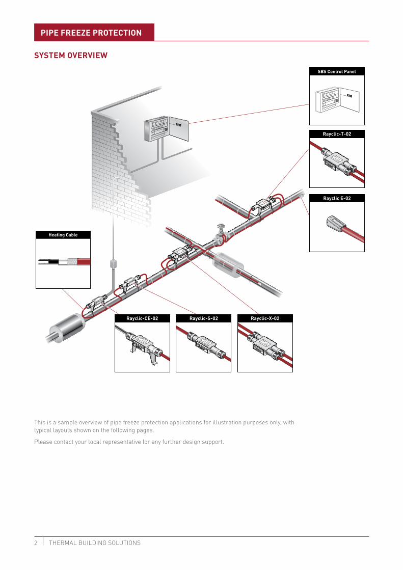
SySTEM OvERviEW
PiPE FREEzE PROTECTiOn
Heating Cable
Rayclic E-02
Rayclic-T-02
T-Connection
SBS Control Panel
Rayclic-CE-02 Rayclic-S-02 Rayclic-X-02
This is a sample overview of pipe freeze protection applications for illustration purposes only, with typical layouts shown on the following pages.
Please contact your local representative for any further design support.

3XL-TRACE LSZH DESIGN GUIDELINES
Rayclic-CE-02
XL-Trace LSZH cable
Rayclic-S-02
Rayclic-T-02
Insulation
Rayclic E-02
Rayclic E-02
Raystat-Eco-10 (ambient sensing)or
Raystat-Control-10 (line sensing)
Raystat-Control-10 (line sensing)
Cold Water Services Low Pressure Hot Water Services(LPHW)
Rayclic-CE-02
XL-Trace LSZH cable
Rayclic-S-02
Rayclic-T-02
Insulation
Rayclic E-02
Rayclic E-02
SingLE CiRCuiT
MuLTiPLE CiRCuiT
PiPE FREEzE PROTECTiOn
Cold Water + LPHW Services
Rayclic-CE-02
XL-TraceLSZH cable
Rayclic-S-02
Rayclic-T-02
Insulation
Rayclic E-02
Rayclic E-02
Junctionbox
SBS panel
Fire Sprinkler Lines(with redundant heat tracing according to EN12845 / VDE)
Rayclic-CE-02
XL-TraceLSZH cable
Insulation
Rayclic E-02
SBS-XX-SNR
Junctionbox
Redundant heating circuit
XL-Trace LSzH cable31 W/m @ 50C
XL-Trace LSzH cable
10 W/m @ 50C 26 W/m @ 50C15 W/m @ 50C
XL-Trace LSzH cablefor fire sprinkler lines
10 W/m @ 50C 26 W/m @ 50C15 W/m @ 50C
XL-Trace LSzH cablefor cold water for LPHW services
10 W/m @ 50C 26 W/m @ 50C 31 W/m @ 50C15 W/m @ 50C

4 THERMAL buiLding SOLuTiOnS
Heat-tracingsystem
ACS-30-EU-UIT2
(Optional)ACS-30-EU-Moni-RMM2-E
COMMON
ALARM
POWER CONTROL
MODULE
ACCS-PCM-5
ACS-30-EU-PCM2
MuLTiPLE CiRCuiTS (AbOvE 12) OR MuLTiPLE APPLiCATiOnS
PiPE FREEzE PROTECTiOn
XL-Trace LSzH cablefor cold water for LPHW services
10 W/m @ 50C 26 W/m @ 50C 31 W/m @ 50C15 W/m @ 50C

5XL-TRACE LSZH DESIGN GUIDELINES
RayClic-S-02
RayClic-PT-02
Heating Cable
Rayclic E-02
Ground Level
Electronic Controller
Line Sensor
SySTEM OvERviEW.
FLOW MAinTEnAnCE (gREASE LinE)
This is a sample overview for flow maintenance of greasy waste pipes for illustration purposes only, with typical layouts shown on the following page.
Please contact your local representative for any further design support.

6 THERMAL buiLding SOLuTiOnS
SBS panel
Rayclic-CE-02
XL-TraceLSZH cable
Rayclic-S-02
Rayclic-T-02
Insulation
Rayclic E-02
Rayclic E-02
Rayclic-CE-02
XL-TraceLSZH cable
Rayclic-S-02
Rayclic-T-02
Insulation
Rayclic E-02
Rayclic E-02
Raystat-Control-10(Line Sensing)
SingLE CiRCuiT
MuLTiPLE CiRCuiT (uP TO 12)
FLOW MAinTEnAnCE (gREASE LinE)
XL-Trace LSzH cable31 W/m @ 50C
XL-Trace LSzH cable31 W/m @ 50C
7XL-TRACE LSZH DESIGN GUIDELINES
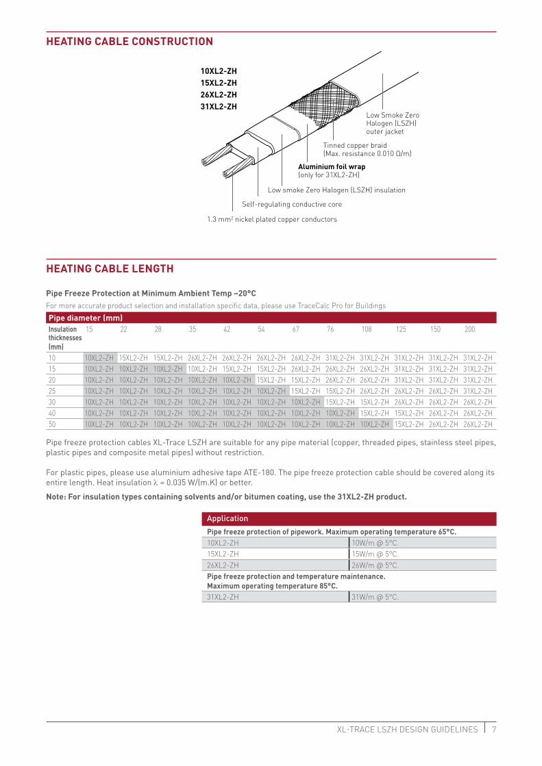
HEATing CAbLE COnSTRuCTiOn
1.3 mm2 nickel plated copper conductors
Low Smoke ZeroHalogen (LSZH)outer jacket
Low smoke Zero Halogen (LSZH) insulation
Self-regulating conductive core
Aluminium foil wrap (only for 31XL2-ZH)
Tinned copper braid(Max. resistance 0.010 Ω/m)
10XL2-zH15XL2-zH26XL2-zH31XL2-zH
HEATing CAbLE LEngTH
Pipe Freeze Protection at Minimum Ambient Temp –20°CFor more accurate product selection and installation specific data, please use TraceCalc Pro for BuildingsPipe diameter (mm)insulation 15 22 28 35 42 54 67 76 108 125 150 200thicknesses (mm)10 10XL2-ZH 15XL2-ZH 15XL2-ZH 26XL2-ZH 26XL2-ZH 26XL2-ZH 26XL2-ZH 31XL2-ZH 31XL2-ZH 31XL2-ZH 31XL2-ZH 31XL2-ZH15 10XL2-ZH 10XL2-ZH 10XL2-ZH 10XL2-ZH 15XL2-ZH 15XL2-ZH 26XL2-ZH 26XL2-ZH 26XL2-ZH 31XL2-ZH 31XL2-ZH 31XL2-ZH20 10XL2-ZH 10XL2-ZH 10XL2-ZH 10XL2-ZH 10XL2-ZH 15XL2-ZH 15XL2-ZH 26XL2-ZH 26XL2-ZH 31XL2-ZH 31XL2-ZH 31XL2-ZH25 10XL2-ZH 10XL2-ZH 10XL2-ZH 10XL2-ZH 10XL2-ZH 10XL2-ZH 15XL2-ZH 15XL2-ZH 26XL2-ZH 26XL2-ZH 26XL2-ZH 31XL2-ZH30 10XL2-ZH 10XL2-ZH 10XL2-ZH 10XL2-ZH 10XL2-ZH 10XL2-ZH 10XL2-ZH 15XL2-ZH 15XL2-ZH 26XL2-ZH 26XL2-ZH 26XL2-ZH40 10XL2-ZH 10XL2-ZH 10XL2-ZH 10XL2-ZH 10XL2-ZH 10XL2-ZH 10XL2-ZH 10XL2-ZH 15XL2-ZH 15XL2-ZH 26XL2-ZH 26XL2-ZH50 10XL2-ZH 10XL2-ZH 10XL2-ZH 10XL2-ZH 10XL2-ZH 10XL2-ZH 10XL2-ZH 10XL2-ZH 10XL2-ZH 15XL2-ZH 26XL2-ZH 26XL2-ZH
Pipe freeze protection cables XL-Trace LSZH are suitable for any pipe material (copper, threaded pipes, stainless steel pipes, plastic pipes and composite metal pipes) without restriction.
For plastic pipes, please use aluminium adhesive tape ATE-180. The pipe freeze protection cable should be covered along its entire length. Heat insulation l = 0.035 W/(m.K) or better.
note: For insulation types containing solvents and/or bitumen coating, use the 31XL2-zH product.
ApplicationPipe freeze protection of pipework. Maximum operating temperature 65°C.10XL2-ZH 10W/m @ 5°C.15XL2-ZH 15W/m @ 5°C.26XL2-ZH 26W/m @ 5°C.Pipe freeze protection and temperature maintenance. Maximum operating temperature 85°C.31XL2-ZH 31W/m @ 5°C.

40°C temperature maintenance on pipelines for fatty waste water
Pipe diameter (mm)insulation 42 54 67 76 108 125 150 200thicknesses 11/2” 2” 21/2” 3” 4” 5” 6” 8”30 mm 31XL2-ZH 40 mm 31XL2-ZH 31XL2-ZH 31XL2-ZH 50 mm 31XL2-ZH 31XL2-ZH 31XL2-ZH 31XL2-ZH 60 mm 31XL2-ZH 31XL2-ZH 31XL2-ZH 31XL2-ZH 31XL2-ZH 31XL2-ZH 31XL2-ZH 31XL2-ZH
Min. ambient temperature –10°C. Heat insulation l = 0.035 W/(m.K) or better.
Cable type 31XL2-ZH should only be used in conjunction with pipework with a minimum continuous temperature resistance of 90°C. A line-sensing control thermostat (type AT-TS-14, RAYSTAT-CONTROL-10 or RAYSTAT-CONTROL-11-DIN) must be used on plastic pipework (setting approx. 40°C).
8 THERMAL buiLding SOLuTiOnS
The heating cable should be installed in a straight line on the pipework. Cable loops instead of T-connections can be made on short dead legs. (up to approx. 3 m)+ approx. 0.3 m per connection+ approx. 1.0 m per T-connection+ approx. 1.2 m per 4-way connectionAdditional cable required for increased heat sinks at valves from 2” and for uninsulated pipe supports (approx. 1 m)
= required heating cable length
• The total length of heating cable determines the number and size of the fuses • Residual current device (rcd) : 30 mA required, max. 500 m heating cable per rcd • Installation according to local regulations • The power connections must be carried out by an approved electrical installer • Use C type circuit-breakers
XL-Trace Maximum Circuit Lengths
10XL2-zH (240 vac) Circuit breaker (C Type characteristic Cb Size)Switch-On Temperature (°C) 4 6 10 13 16 20
–20 25 40 75 100 140 180–10 30 50 90 130 170 190
–5 40 60 110 150 190 2000 45 70 125 170 210 2105 50 80 140 195 215 215
15XL2-zH (240 vac) Circuit breaker (C Type characteristic Cb Size)Switch-On Temperature (°C) 4 6 10 13 16 20
–20 10 25 50 70 90 120–10 12 30 60 85 110 145
–5 25 40 70 95 120 1550 29 45 80 110 135 1605 35 50 90 120 155 160
CAbLE LEngTH
ELECTRiCAL PROTECTiOn

9XL-TRACE LSZH DESIGN GUIDELINES
XL-Trace Maximum Circuit Lengths26XL2-zH (240 vac) Circuit breaker (C Type characteristic Cb Size)Switch-On Temperature (°C) 4 6 10 13 16 20
–20 12 12 40 55 80 110–10 12 25 50 70 100 125
–5 12 30 55 85 110 1300 12 35 70 100 125 1355 20 40 80 110 135 135
31XL2-zH (240 vac) Circuit breaker (C Type characteristic Cb Size)Switch-On Temperature (°C) 4 6 10 13 16 20
–20 15 25 50 65 80 105–10 20 30 55 75 90 115
–5 22 35 59 79 100 1180 24 38 64 85 105 1185 26 40 67 88 110 118
TESTing OF THE inSTALLATiOn For testing and commissioning of the XL-Trace LSZH heater cables, please consult the installation and commissioning manual, reference CDE1547.
COnTROL PAnELS Line-sensing thermostat• Adjustable temperature range: 0°C to 150°C• Max. switching current 25 A, 250 VAC• Alarm relay: 2 A voltfree with indication of sensor errors, voltage errors
and low or high temperature alarm• Display for visual indication of parameters
SbS-03-Sv Switch cabinet for 1 to 3 heating circuits.• PCN:355825-000
SbS-06-Sv Control panel for 4 to 6 heating circuits.• PCN:778308-000
SbS-09-Sv Control panel for 7 to 9 heating circuits.• PCN:767989-000
SbS-12-Sv Control panel for 10 to 12 heating circuits.• PCN:1244-000025

10 THERMAL buiLding SOLuTiOnS
Cabinet type SBS-03-SV SBS-06-SV SBS-09-SV SBS-12-SVMax. number of heating circuits 3 6 9 12Enclosure version Wall version Wall version Wall version Wall versionDimensions Width mm 400 400 400 400
Height mm 600 600 600 600Depth mm 210 210 210 210
Weight approx. kg 32 32 32 32Maximum Nominal Current A 25 32 63 80
When using standard control panels for pipe freeze protection additional control devices need to be installed. Factory fitting is possible. Please contact Pentair.
Steel plate housing, wall-mounted version, equipped with mains power switch,low-voltage (LV) relay, RCD/CB combination(s), buzzer, power contactor(s),auxiliary contactor(s), operating mode selector switch, Indicators for `Operatingand Fault‘, `Mains power‘, inlet and outlet terminals. Completely assembled,wired and inspected. Wiring schematics included in housing 1 temperaturecontroller is installed per heating circuit in the switch cabinet.
SbS-02-SnR Control panel for 2 heating circuits (Inc. redundant).
SbS-04-SnR Control panel for 4 heating circuits (Inc. redundant).
SbS-06-SnR Control panel for 6 heating circuits (Inc. redundant).
SbS-08-SnR Control Panel for 8 heating circuits (Inc. redundant).
SbS-10-SnR Control panel for 10 heating circuits (Inc. redundant).
SbS-12-SnR Control panel for 12 heating circuits (Inc. redundant).
FOR SPRinkLER SySTEMS

11XL-TRACE LSZH DESIGN GUIDELINES
Cabinet type SBS-02-SNR
SBS-04-SNR
SBS-06-SNR
SBS-08-SNR
SBS-10-SNR
SBS-12-SNR
Number of pipes 1 2 3 4 5 6Number of heating circuits (Including redundant heating circuit)
2 4 6 8 10 12
Dimensions Width mm 600 800 800 800 1000 1000Height mm 600 800 800 1000 1000 1000Depth mm 210 210 210 300 300 300
Weight kg 45 90 90 115 140 140Max. nominal current (InA) Amps 32 32 32 63 63 63Colour RAL 7035 7035 7035 7035 7035 7035
Main isolator switch rating Amps 32 32 32 63 63 63Circuit breaker sizing Amps 16 16 16 16 16 16Short circuit current range (Icc) kA 10 10 10 10 10 10Controller setpoint (Primary) +8C +8C +8C +8C +8C +8CController setpoint (Redundant) +5C +5C +5C +5C +5C +5C
THERMOSTATS
AT-TS-13
6 0 3 0
0 9 0
1 2 0
C °
A T -T S - 1 3
Thermostat• Adjustabletemperaturerange:–5°Cto+15°C• Line-sensingcontrolthermostatorambientthermostat• Max.switchingcurrent16A,250VAC
note: When selecting the AT-TS-** thermostats, ensure that the maximum circuit length for a 16A circuit is not exceeded.
AT-TS-14
6 0 3 0
0 9 0
1 2 0
C °
A T -T S - 1 4
Thermostat• Adjustabletemperaturerange:0°Cto120°C• Temperaturemaintenanceonpipelinesforfattywastewater• Line-sensingcontrolthermostat• Max.switchingcurrent16A,250VAC note: When selecting the AT-TS-** thermostats, ensure that the maximum circuit length for a 16A circuit is not exceeded.

12 THERMAL buiLding SOLuTiOnS
RAySTAT-ECO-10 Ambient temperature thermostat• Adjustable temperature range: 0°C to 30°C• Max. switching current 25 A, 250 VAC• PASC (Proportional Ambient Sensing Control) for energy saving• Alarm relay: 2 A voltfree with indication of sensor errors, voltage errors
and low or high temperature alarm• Display for visual indication of parameters
RAySTAT-COnTROL-10 Line-sensing thermostat• Adjustable temperature range: 0°C to 150°C• Max. switching current 25 A, 250 VAC• Alarm relay: 2 A voltfree with indication of sensor errors, voltage errors
and low or high temperature alarm• Display for visual indication of parameters
RAySTAT-COnTROL-11-din Line sensing thermostat with digital display for DIN rail mounting applications. • Set temperature range: 0 - 65°C.• Digital display of maintain temperature and alarm information.• 16A switching.• Low temperature alarm function• DINrail/Panelmountablecontrol.• Sensor type: PT100.
Sb-100 Stainless steel support bracket• Specially constructed to provide heating cable protection between pipe and
junction box via a tubular leg.• ForusewithAT-TS-13,AT-TS-14,JB16-02andRAYSTAT-CONTROL-10
13XL-TRACE LSZH DESIGN GUIDELINES
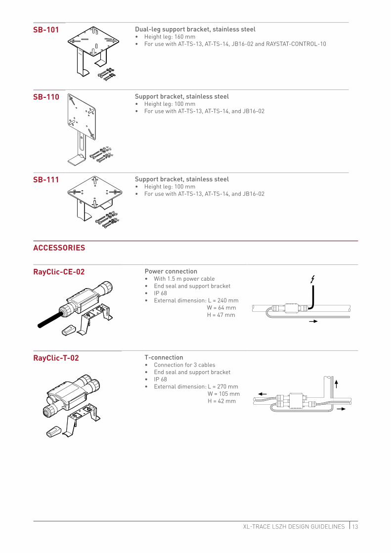
Sb-101 Dual-leg support bracket, stainless steel• Height leg: 160 mm• ForusewithAT-TS-13,AT-TS-14,JB16-02andRAYSTAT-CONTROL-10
Sb-110 Support bracket, stainless steel• Height leg: 100 mm• For use with AT-TS-13, AT-TS-14, and JB16-02
Sb-111 Support bracket, stainless steel• Height leg: 100 mm• For use with AT-TS-13, AT-TS-14, and JB16-02
ACCESSORiES
RayClic-CE-02 Power connection• With 1.5 m power cable• End seal and support bracket• IP 68 • External dimension: L = 240 mm
W = 64 mm H = 47 mm
RayClic-T-02 T-connection• Connection for 3 cables• End seal and support bracket• IP 68 • External dimension: L = 270 mm
W = 105 mm H = 42 mm

14 THERMAL buiLding SOLuTiOnS
RayClic-PT-02 Power T-connection• 3 connections with integral 1.5 m
power cable• 3 end seals and 1 support bracket• IP 68 • External dimension: L = 270 mm
W = 105 mm H = 42 mm
RayClic-S-02 Splice for joining 2 lengths of heating cable• Connectionfor2cableswith1supportbracket• IP68• Externaldimension:L=240mm
W = 64 mm H = 47 mm
RayClic-PS-02 Powered splice• Connectionfor2cableswithintegral1.5mpowercable• 2endsealsand1supportbracket• IP68• Externaldimension:L=270mm
W = 105 mm H = 42 mm
RayClic-X-02 4-way connection• Connectionfor4cables• 2endsealsand1supportbracket• IP68• Externaldimension:L=270mm
W = 105 mm H = 42 mm
RayClic-E-02 Gel-filled end seal• Forsystemextensions(tobeorderedseparately)• IP68
Jb16-02 Temperature-resistant junction box• For power connection• IP66• 6 x 4 mm2 terminals• 4 Pg 11/16, 4 M20/25 knock-out entries
JB 16-02
A C 6 6 0 V
I P 6 6

15XL-TRACE LSZH DESIGN GUIDELINES
kbL-10 Cable ties• Onepackof100requiredforapprox.30mofpipework• Length:370mm• TemperatureandUVresistant
Use ATE-180 on plastic pipes
gT-66 Heat-resistant glass cloth tape• Forsteelpipesorforanyinstallationbelow4.4°C• 20mrollforapprox.20mofpipework
Use ATE-180 on plastic pipes
gS-54 Glass cloth tape for attaching heating cable to pipe
• Forstainless-steelpipesorforanyinstallationbelow4.4°C• 16mperroll,12mmwidth
ATE-180 Aluminium adhesive tape• Heatresistant• 55mrollforapprox.50mofpipework
On plastic pipes: the heating cable must be covered with aluminium adhesive tape along its entire length
iEk-20-M Insulation entry kit• Insertionofheatingcableinmetalcladding• Consistsof:metalfastener,metricglandandjointseal
LAb-i-01 Electric traced label• Tobeplacedat5mintervalsoninsulationsurface
SPECiAL inSTALLATiOn inSTRuCTiOnS PLACing OF SEnSOR
Ambient sensor Fasten the pipe sensor to the pipe-work (e.g. alu min i um adhesive tape)
Always place the sensor in the coldest part of the installation
Unheated premises
Outdoors
Junction box
Heating cable
Sensor
ELECTRICTRACED
R
16 THERMAL buiLding SOLuTiOnS
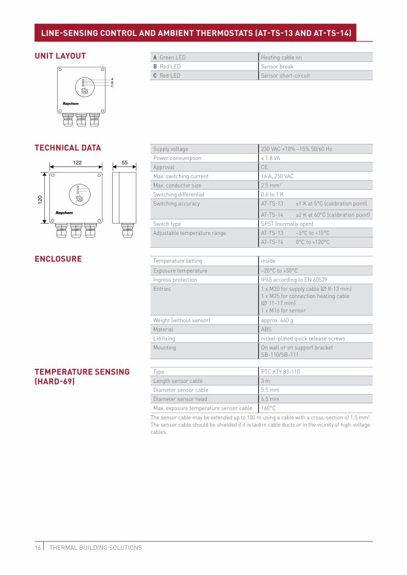
A Green LED Heating cable onb Red LED Sensor breakC Red LED Sensor short-circuit
Supply voltage 230 VAC +10% –15% 50/60 HzPower consumption ≤ 1.8 VAApproval CEMax. switching current 16 A, 250 VACMax. conductor size 2.5 mm2
Switching differential 0.6 to 1 KSwitching accuracy AT-TS-13 ±1 K at 5°C (calibration point)
AT-TS-14 ±2 K at 60°C (calibration point)Switch type SPST (normally open)Adjustable temperature range AT-TS-13 –5°C to +15°C
AT-TS-14 0°C to +120°C
Temperature setting insideExposure temperature –20°C to +50°CIngress protection IP65 according to EN 60529Entries 1 x M20 for supply cable (∅ 8-13 mm)
1 x M25 for connection heating cable (∅ 11–17 mm) 1 x M16 for sensor
Weight (without sensor) approx. 440 gMaterial ABSLid fixing nickel-plated quick release screwsMounting On wall or on support bracket
SB-110/SB-111
Type PTC KTY 83-110Length sensor cable 3 mDiameter sensor cable 5.5 mmDiameter sensor head 6.5 mmMax. exposure temperature sensor cable 160°C
The sensor cable may be extended up to 100 m using a cable with a cross-section of 1.5 mm2. The sensor cable should be shielded if it is laid in cable ducts or in the vicinity of high-voltage cables.
55
R
122
120
R
ABC
uniT LAyOuT
TECHniCAL dATA
LinE-SEnSing COnTROL And AMbiEnT THERMOSTATS (AT-TS-13 And AT-TS-14)
EnCLOSuRE
TEMPERATuRE SEnSing(HARd-69)

17XL-TRACE LSZH DESIGN GUIDELINES
max. 16A/C
1 2
4 9 8 6
5 3
30 mA
L1
N
*
Thermostat
Temp. Pt 100 sensor
Self-regulating heating cable
L1
L2
L3
N
**
***
max. 16A/C
1 2 3
9 8 6
5
*
4
30 mA
*
6 0 3 0
0 9 0
1 2 0
C °
A T -T S - 1 3
Thermostat
Self-regulating heating cable
AT-TS-13/14 diRECT
WiRing diAgRAM FOR THERMOSTAT AT-TS-13 OR AT-TS-14
AT-TS-13/14 WiTH COnTACTOR
Temp. Pt 100 sensor
* Two- or four-pole electrical pro-tection by circuit-breaker may be needed for local circumstances, standards and regulations
** Depending on the application, one- or three-pole circuit-breakers or contactors may be used
*** Optional: Potential-free circuit-breaker for connection to the BMS
18 THERMAL buiLding SOLuTiOnS
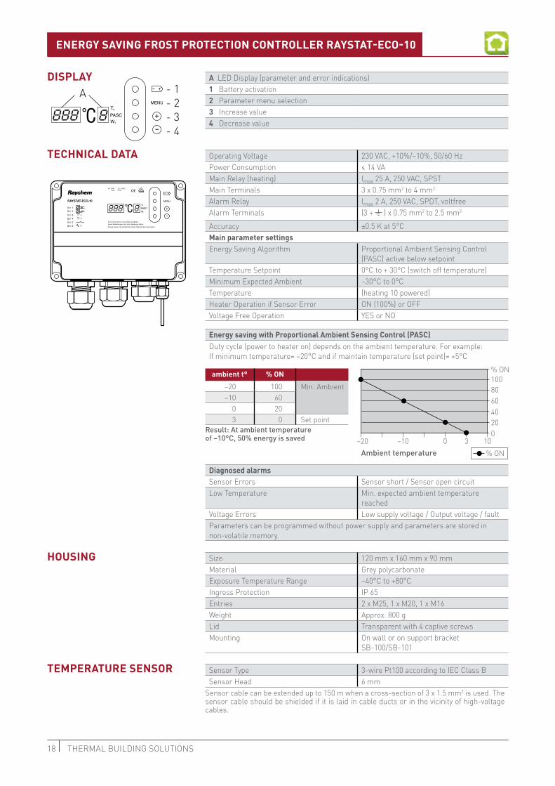
A LED Display (parameter and error indications)1 Battery activation2 Parameter menu selection 3 Increase value4 Decrease value
Operating Voltage 230 VAC, +10%/–10%, 50/60 HzPower Consumption ≤ 14 VA Main Relay (heating) Imax 25 A, 250 VAC, SPSTMain Terminals 3 x 0.75 mm2 to 4 mm2
Alarm Relay Imax 2 A, 250 VAC, SPDT, voltfreeAlarm Terminals (3 + ) x 0.75 mm2 to 2.5 mm2
Accuracy ±0.5 K at 5°CMain parameter settingsEnergy Saving Algorithm Proportional Ambient Sensing Control
(PASC) active below setpointTemperature Setpoint 0°C to + 30°C (switch off temperature)Minimum Expected Ambient –30°C to 0°C Temperature (heating 10 powered)Heater Operation if Sensor Error ON (100%) or OFFVoltage Free Operation YES or NO
Energy saving with Proportional Ambient Sensing Control (PASC)Duty cycle (power to heater on) depends on the ambient temperature. For example: If minimum temperature= –20°C and if maintain temperature (set point)= +5°C
diagnosed alarmsSensor Errors Sensor short / Sensor open circuitLow Temperature Min. expected ambient temperature
reachedVoltage Errors Low supply voltage / Output voltage / faultParameters can be programmed without power supply and parameters are stored in non-volatile memory.
Size 120 mm x 160 mm x 90 mmMaterial Grey polycarbonateExposure Temperature Range –40°C to +80°CIngress Protection IP 65 Entries 2 x M25, 1 x M20, 1 x M16Weight Approx. 800 gLid Transparent with 4 captive screwsMounting On wall or on support bracket
SB-100/SB-101
Sensor Type 3-wire Pt100 according to IEC Class BSensor Head 6 mm
Sensor cable can be extended up to 150 m when a cross-section of 3 x 1.5 mm2 is used. The sensor cable should be shielded if it is laid in cable ducts or in the vicinity of high-voltage cables.
- 1- 2- 3- 4
A
VD E
EnERgy SAving FROST PROTECTiOn COnTROLLER RAySTAT-ECO-10
Ambient temperature–10 0 3 10
% ON
0 20 40 60 80 100
% ON
ambient t° % On–20 100 Min. Ambient–10 60
0 203 0 Set point
Result: At ambient temperature of –10°C, 50% energy is saved
diSPLAy
TECHniCAL dATA
HOuSing
TEMPERATuRE SEnSOR
–20

19XL-TRACE LSZH DESIGN GUIDELINES
Heating cable
Temp. Pt 100 sensor
Heating cable Temp. Pt 100 sensor
WiRing diAgRAM FOR RAySTAT-ECO-10
nORMAL OPERATiOn
vOLTAgE FREE OPERATiOn: REMOvE LinkS W1 And W2
* Electrical protection by circuit breaker may be needed for local circumstances, standards and regulations.
** Depending on the application, one or three-pole circuit breakers or contactors may be used.
20 THERMAL buiLding SOLuTiOnS
- 1- 2- 3- 4
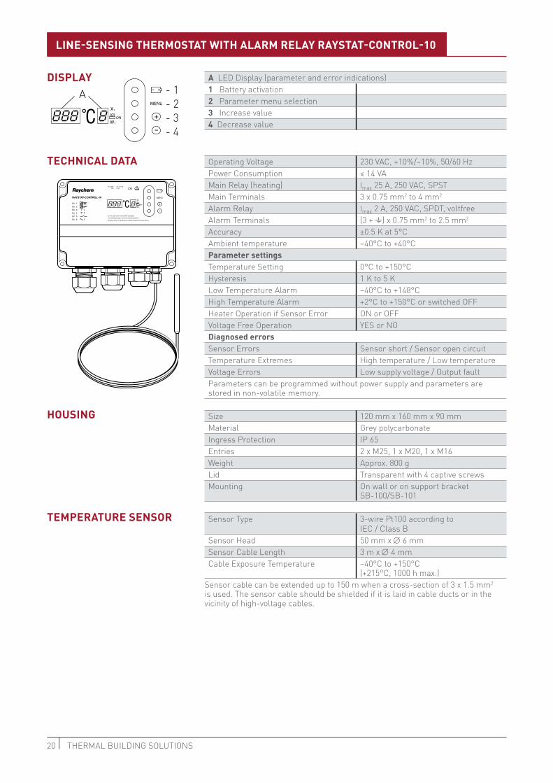
AA LED Display (parameter and error indications)1 Battery activation2 Parameter menu selection3 Increase value4 Decrease value
Operating Voltage 230 VAC, +10%/–10%, 50/60 HzPower Consumption ≤ 14 VA Main Relay (heating) Imax 25 A, 250 VAC, SPSTMain Terminals 3 x 0.75 mm2 to 4 mm2
Alarm Relay Imax 2 A, 250 VAC, SPDT, voltfreeAlarm Terminals (3 + ) x 0.75 mm2 to 2.5 mm2
Accuracy ±0.5 K at 5°CAmbient temperature –40°C to +40°CParameter settingsTemperature Setting 0°C to +150°CHysteresis 1 K to 5 KLow Temperature Alarm –40°C to +148°CHigh Temperature Alarm +2°C to +150°C or switched OFFHeater Operation if Sensor Error ON or OFFVoltage Free Operation YES or NOdiagnosed errorsSensor Errors Sensor short / Sensor open circuitTemperature Extremes High temperature / Low temperatureVoltage Errors Low supply voltage / Output faultParameters can be programmed without power supply and parameters are stored in non-volatile memory.
Size 120 mm x 160 mm x 90 mmMaterial Grey polycarbonateIngress Protection IP 65 Entries 2 x M25, 1 x M20, 1 x M16Weight Approx. 800 gLid Transparent with 4 captive screwsMounting On wall or on support bracket
SB-100/SB-101
Sensor Type 3-wire Pt100 according to IEC / Class B
Sensor Head 50 mm x ∅ 6 mmSensor Cable Length 3 m x ∅ 4 mmCable Exposure Temperature –40°C to +150°C
(+215°C, 1000 h max.)Sensor cable can be extended up to 150 m when a cross-section of 3 x 1.5 mm2 is used. The sensor cable should be shielded if it is laid in cable ducts or in the vicinity of high-voltage cables.
VD E
LinE-SEnSing THERMOSTAT WiTH ALARM RELAy RAySTAT-COnTROL-10
diSPLAy
TECHniCAL dATA
HOuSing
TEMPERATuRE SEnSOR

21XL-TRACE LSZH DESIGN GUIDELINES
WiRing diAgRAM FOR RAySTAT-COnTROL-10
nORMAL OPERATiOn
vOLTAgE FREE OPERATiOn: REMOvE LinkS W1 And W2
LN
1
Max.C 25 A
30 mA
5 L L 8 N N
W1 W2
R R
RAYSTAT-CONTROL-10
A B C
alarm*2A max.
Heating cable Temp. Pt 100 sensor
Heating cable Temp. Pt 100 sensor
* Electrical protection by circuit breaker may be needed for local circumstances, standards and regulations
** Depending on the application, one or three-pole circuit breakers or contactors may be used
*** Optional
22 THERMAL buiLding SOLuTiOnS
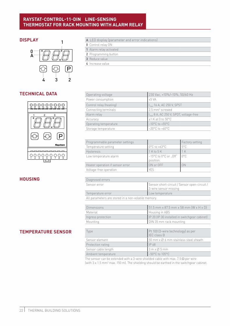
RAySTAT-COnTROL-11-din LinE-SEnSing THERMOSTAT FOR RACk MOunTing WiTH ALARM RELAy
A LED display (parameter and error indications)0 Control relay ON1 Alarm relay activated2 Programming button3 Reduce value4 Increase value
Operating voltage 230 Vac, +10%/–10%, 50/60 HzPower consumption ≤5 VAControl relay (heating) Imax 16 A, AC 250 V, SPSTConnecting terminals 2.5 mm2 screwedAlarm relay Imax 8 A, AC 250 V, SPDT, voltage-freeAccuracy ±1 K at 0 to 50°COperating temperature –10°C to +55°CStorage temperature –20°C to +60°C
Programmable parameter settings Factory settingTemperature setting 0°C to +63°C 5°CHysteresis 1 K to 5 K 1 KLow temperature alarm –15°C to 0°C or „Off“
position.0°C
Heater operation if sensor error ON or OFF ONVoltage-free operation YES
Diagnosed errorsSensor error Sensor short-circuit / Sensor open-circuit /
3-wire sensor missingTemperature error Low temperatureAll parameters are stored in a non-volatile memory.
Dimensions 51.5 mm x 87.5 mm x 58 mm (W x H x D)Material Housing in ABSIngress protection IP 20 (IP 30 installed in switchgear cabinet)Mounting DIN 35 mm rack mounting
Type Pt 100 (3-wire technology) as per IEC class B
Sensor element 50 mm x ∅ 6 mm stainless steel sheathProtection rating IP 68Sensor cable length 3 m x ∅ 5 mmAmbient temperature –50°C to 105°C
The sensor can be extended with a 3-wire shielded cable with max. 7.5 Ω per wire (with 3 x 1.5 mm2 max. 150 m). The shielding should be earthed in the switchgear cabinet.
diSPLAy
TECHniCAL dATA
HOuSing
TEMPERATuRE SEnSOR
4 3 2
A0
1

23XL-TRACE LSZH DESIGN GUIDELINES
WiRing diAgRAM FOR RAySTAT-COnTROL-11-din
RAYSTAT-CONTROL-11-DIN
10 11 16 17 18
4 5 6 7 8 9
16 17 18
K2 Alarm
K1heatingcable
L N (AC 230V)
Heating cable
2-wire sensor3-wire sensor
MaxC 16A
2A
30 mA
Network mains
Heating cable
10 11 16 17 18
4 5 6 7 8 9
16 17 18
2-wire sensor3-wire sensor
Network mains
K2 alarm
K1heating cable
L N (AC 230V)
Max.C 16A
2A
nORMAL OPERATiOn
vOLTAgE-FREE OPERATiOn WiTH POWER COnTACTOR
* Regional factors, standards and regulations may require two to four-pole disconnection by circuit breakers/ground fault circuit interrupters.
** Depending on the application, both single and multipole contactors are possible.

24 THERMAL buiLding SOLuTiOnS
ca. 45° ca. 45°
inSTALLATiOn inSTRuCTiOnS FOR XL-TRACE LSzH CAbLES• Theheatingcableshouldbeinstalledinastraightlineonthepipework.• Installondrysurfaces• Minimuminstallationtemperature:–20°C
installation of self-regulating heating cables• Storeinadryandcleanplace.• Temperaturerange:–40°Cto+60°C.• Protectanycableendswithanendseal.
Avoid:• sharpedges• hightractiveforce• kinkingandcrushing• walkingordrivingoverthecable• moistureatcableinterfaces
horizontal pipes
For plastic pipes use aluminium adhesive tape ATE-180. Place it over the entire length of the pipe
GT-66 / GS-54 adhesive tape
It is not necessary to spiral the cable around the pipe
Install the heating cables on the outside of the pipe bend
Cable tie KBL-10
90°
Cut the heating cable at right angles
Smallest bending radius: 10 mm
Horizontal pipe
vertical pipe
max. 300 mm
PIPE FREEZE PROTECTION

25XL-TRACE LSZH DESIGN GUIDELINES
ca. 45° ca. 45°
RayClic-T-connection Electric traced label
IEK-20-M for insertion of heating cable in metal cladding
≤ 3 m
≤ 3 m
> 3 m
> 3m + Rayclic
RayClic
• Runthecableoverpipesuspensions• Donotclampthecable
Wall/Floor transitThe thickness of thermal insulation must be continuous otherwise compensate by adding heating cable.
Frost protection at valves:• Valvesupto2”(DN50):installthe
frost protection heating cables in a straight line
• ≥2”:layasshown• Alwaysinsulatevalves


United KingdomTel:0800969013Fax:[email protected]
irelandTel: 1800 654 241Fax: 1800 654 [email protected]
SoUth eaSt aSiaTel:+6567685800Fax:+6567322263
aUStraliaTel:+61297920250Fax:[email protected]
india - noidaTel:+911204649500Fax:[email protected]
india - mUmBaiTel:+912267758800/01Fax:[email protected]
UaeTel:+97143781700Fax:[email protected]
Raychem-DG-EU0668-XLTraceDesignGuide-EN-1702THERMAL buiLding SOLuTiOnS
WWW.Pentairthermal.Com
Pentair is owned by Pentair or its global affiliates. All other trademarks are the property of their respective owners. Pentair reserves the right to change specifications without prior notice.
© 2017 Pentair.


