
Design Guides 3.3.21 - LRFD Bolted Splice Design
April 2012 Page 3.3.21-1
3.3.21 LRFD Bolted Splice Design for Composite Structures This design guide contains a procedural outline for the design of bolted field splices in main
flexural members near points of dead load contraflexure using the LRFD Code. The focus is on
splices for straight bridges which are composite throughout the structure. A worked design
example is also included. The design example is consistent with Design Guide 3.3.4 in beam
size, span length, skew, etc. Skew effects are included in the design of the composite splice
and are calculated using the simplification in Chapter 6 of the LRFD Code.
The differences in the provisions between the LRFD and LFD Codes are minor and are not
accounted for in this design guide.
The primary articles for bolted splice design of flexural members in the LRFD Code are
1. General (6.13.6.1.4a)
2. Flange Splices (6.13.6.1.4c)
3. Web Splices (6.13.6.1.4b)
LRFD Splice Design Procedure, Equations, and Outline
Composite splice design is similar to non-composite splice design with the exception that
composite properties are used for applicable stress calculations.
As per Section 3.3.21 of the Bridge Manual, splices should be placed near points of dead load
contraflexure. These points are typically in regions of stress reversal, and as such according to
Article C6.13.6.1.4a they shall be checked for both positive and negative flexure to determine
the controlling case. For the purpose of the included example design, compression stresses are
positive and tension stresses are negative.
If splices are placed at points of contraflexure, the dead and live loads should be close to zero
for constructability checks. While the effects of pouring sequences will induce moments at the
point of dead load contraflexure, these moments are not expected to induce stresses that will

Design Guides 3.3.21 - LRFD Bolted Splice Design
Page 3.3.21-2 April 2012
control over the stresses in the final load condition. A quick stress check for constructability is
typically all that is required to determine that constructability does not control.
When determining locations of splices, note that there is a penalty on the Cb term used in beam
design for changes in section that are not within 20% of the unbraced length near the brace
point with the smaller moment. See Article 6.10.8.2.3. This should be acknowledged during
framing plan setup as it can be avoided with proper diaphragm and splice placement. Typically
if a diaphragm and splice are both placed near a point of dead load contraflexure this penalty
will not be applicable.
The assumptions for section properties and stress calculation found in other sections of Chapter
6 are applicable to splice design. Despite the fact that it is current IDOT policy to not include
stud shear connectors on flange splice plates, the section shall be assumed as composite in
both positive and negative flexure at splice locations.
Transformed and cracked section properties need to be calculated. As the bridge in this design
guide is consistent with the bridge in Design Guide 3.3.4, to avoid repetition, calculations for
some of the section properties for the given structure are not repeated in this design guide but
rather may be found in Design Guide 3.3.4.
According to Article 6.13.1, splices should be designed for the factored forces at the location of
the splice, but shall not be designed for less than 75 percent of the factored resistance of the
member.
Determine Flange Stresses
Stresses shall be calculated at the mid-thickness of each flange (C6.13.6.1.4c).
Stresses shall be determined using the gross section properties (6.13.6.1.4a).
f =
IMc
Where:

Design Guides 3.3.21 - LRFD Bolted Splice Design
April 2012 Page 3.3.21-3
f = flange stress (ksi)
M = moment from the load (k-in.)
c = distance from the neutral axis to the mid-thickness of the flange for which the
stress is calculated (in.)
I = moment of inertia of the applicable section of the beam or girder (in.4). Different
moments of inertia are used for different checks. The following is a summary of
what moments of inertia should be used:
For DC1 loading, the steel section alone is used.
For DC2 and DW loading in the positive moment region, the long-term composite
transformed section is used.
For LL+IM loading in the positive moment region, the short-term composite
transformed section is used.
For Service II negative moment checks, an uncracked transformed section may
be used if the total tension in the deck ( )
+
+
=
+
= 9n
IMLL
27n
DW2DC
SM3.1
n1
SMM
n31 does
not exceed twice the modulus of rupture for the deck (2fr). See 6.10.4.2.1.
For Fatigue negative moment checks, an uncracked transformed section may
always be used. See 6.6.1.2.1.
For all other negative moment checks, a cracked section should always be used.
Strength I Stresses
Use the dead load and controlling live load plus impact stresses to calculate the Strength
I load case flange stresses. Controlling positive and negative live loads, as defined in
Article 3.6.1.2, shall be investigated in stress calculations. Stresses shall be factored
according to Article 3.4.1, using the maximum and minimum factors. To obtain critical
stresses, use the appropriate factors and exclude fDW if a more conservative result is
obtained.

Design Guides 3.3.21 - LRFD Bolted Splice Design
Page 3.3.21-4 April 2012
fu = γDC1(fDC1) + γDC2(fDC2) + γDW(fDW) + 1.75(fLL+IM) + fl
Where:
γDC1 = 1.25 or 0.90
γDC2 = 1.25 or 0.90
γDW = 1.50 or 0.65
fDC1 = unfactored stress calculated from DC1 moment (ksi)
fDC2 = unfactored stress calculated from DC2 moment (ksi)
fDW = unfactored stress calculated from DW moment (ksi)
fLL+IM = unfactored stress calculated from LL+IM moment (ksi)
fl = lateral flange bending stress. For top splice plates this should always be
taken as zero. For bottom splice plates, the effects of skew currently may
be ignored. The effects of curvature should be accounted for.
Service II Stresses
Use the dead load and controlling live load plus impact stresses to calculate Service II
flange stresses. Controlling positive and negative live loads, as defined in Article
3.6.1.2, shall be investigated in stress calculations. Stresses shall be factored according
to Article 3.4.1. To obtain critical Service II stresses, fDW may be excluded if a more
conservative result is obtained.
fo = 1.0(fDC1) + 1.0(fDC2) + 1.0(fDW) + 1.3(fLL+IM) + fl
Fatigue Stresses
Use the fatigue truck plus impact stresses to calculate Fatigue flange stresses (3.6.1.4).
Stresses shall be factored according to Article 3.4.1. Positive and negative fatigue
forces shall be investigated.
The fatigue and fracture limit state uses the fatigue load combinations found in Table
3.4.1-1:
γ(fr) = γ(fLL+IM) + fl
Where:

Design Guides 3.3.21 - LRFD Bolted Splice Design
April 2012 Page 3.3.21-5
γ = 1.5 for Fatigue I loading and 0.75 for Fatigue II loading
Whether Fatigue I or Fatigue II limit state is used depends upon the amount of
fatigue cycles the member is expected to experience throughout its lifetime. For
smaller amounts of cycles, Fatigue II, or the finite life limit state, is used. As the
amounts of cycles increase, there comes a point where use of finite life limit state
equations becomes excessively conservative, and use of the Fatigue I, or infinite life
limit state, becomes more accurate.
To determine whether Fatigue I or Fatigue II limit state is used, the single-lane
average daily truck traffic (ADTT)SL at 75 years must first be calculated. (ADTT)SL is
the amount of truck traffic in a single lane in one direction, taken as a reduced
percentage of the Average Daily Truck Traffic (ADTT) for multiple lanes of travel in
one direction.
(ADTT)75, SL = p × ADTT75 (Eq. 3.6.1.4.2-1)
Where:
p = percentage of truck traffic in a single lane in one direction, taken from
Table 3.6.1.4.2-1.
ADTT75 is the amount of truck traffic in one direction of the bridge at 75 years.
Type, Size, and Location reports usually give ADTT in terms of present day and
20 years into the future. The ADTT at 75 years can be extrapolated from this
data by assuming that the ADTT will grow at the same rate i.e. follow a straight-
line extrapolation using the following formula:
ADTT75 = ( ) ( )DDADTTyears20years57ADTTADTT 0020
+
−
Where:
ADTT20 = ADTT at 20 years in the future, given on TSL
ADTT0 = present-day ADTT, given on TSL

Design Guides 3.3.21 - LRFD Bolted Splice Design
Page 3.3.21-6 April 2012
DD = directional distribution, given on TSL
The designer should use the larger number given in the directional distribution.
For example, if the directional distribution of traffic was 70% / 30%, the ADTT for
design should be the total volume times 0.7 in order to design for the beam
experiencing the higher ADTT. If a bridge has a directional distribution of 50% /
50%, the ADTT for design should be the total volume times 0.5. If a bridge is
one-directional, the ADTT for design is the full value, as the directional
distribution is 100% / 0% i.e. one.
When (ADTT)75, SL is calculated, it is compared to the infinite life equivalent found in
Table 6.6.1.2.3-2. If the calculated value of (ADTT)75, SL exceeds the value found in
this table, then the infinite life (Fatigue I) limit state is used. If not, the finite life
(Fatigue II) limit state is used.
Determine Trial Flange Splice Plates
To begin a design, trial flange splice plates are chosen. Each flange plate shall be a
minimum ½ in. thick and shall extend as near to the beam or girder width as possible. If
flange widths transition at the splice location, size the flange splice plate to the smaller
width. Also, commonly available plate thicknesses should be used for splice plates. See
Section 3.3.21 of the Bridge Manual.
Use of inside splice plates will greatly reduce the required number of bolts, as the bolts can
be considered doubly effective in shear. This, in turn, will greatly reduce the length of the
splice plates, which will allow for more flange space for shear studs and reduce the
probability of interference with a stiffener or diaphragm. Therefore, it is recommended that
inside splice plates be used when possible.
It should be noted that there are cases where flange geometry disallows the use of inside
splice plates. Inside splice plates should never be used unless there are a minimum of four
rows of bolts in the flange splice plate (two rows per side of flange). If only one row is
present on a side of a flange, this may cause significant bowing/cupping of the inside plate
when the bolts are tightened. The geometry of Bridge Manual Figures 3.3.21-2 and 3.3.21-3

Design Guides 3.3.21 - LRFD Bolted Splice Design
April 2012 Page 3.3.21-7
dictates that inside splice plates may not be used unless the flange is a minimum of 12
inches wide.
When choosing sizes of inside plates, Bridge Manual 3.3.21 suggests that the area of the
inside plates be within 10% of the area of the outside plate. The purpose of this is so that
the assumption of double shear in the bolts is valid (i.e. around 50% of the load is actually
going through each shear plane). This may result in inside plates being slightly thicker than
outside plates. Also, if the plate thicknesses are dictated by the minimum ½ in. thickness,
addition of inside plates to an already excessively thick outside plate may result in splices
with much higher capacities than required. However, the addition of the inside plates will
also greatly reduce the required length of the splice plates, so even though the capacity is
much higher, the amount of additional steel may be negligible.
Calculate Flange Effective Area, Ae (6.13.6.1.4c)
The effective area for tension flanges is found as:
Ae = gnyty
uu AAFF
≤
φφ
(Eq. 6.13.6.1.4c-2)
The effective area for compression flanges is found as:
Ae = Ag (6.13.6.1.4c)
Where:
φu = 0.80 (6.5.4.2)
φy = 0.95 (6.5.4.2)
Fu = specified minimum tensile strength of tension flange (ksi) (Table 6.4.1-1)
Fyt = specified minimum yield strength of tension flange (ksi)
Ag = gross area of the applicable flange (in.2)
An = net area of the applicable flange = Wnt (in.2)
In which:
Wn = net width of the applicable flange, as defined in 6.8.3 as the smallest width
across a chain of holes in any transverse, diagonal, or zigzag line (in.). When

Design Guides 3.3.21 - LRFD Bolted Splice Design
Page 3.3.21-8 April 2012
subtracting the hole widths, the actual hole size found in Table 6.13.2.4.2-1
should be used. Additional subtractions due to damage due to punching are
not applicable, as Article 505.04(d) of the Standard Specifications does not
allow punching of holes for field splices for beams.
t = thickness of the applicable flange (in.)
Determine Strength I Controlling and Non-controlling Flange Stresses
Compare Strength I flange stresses. The largest ratio of flange stress to flange capacity will
determine which flange has the controlling stress, fcf. The corresponding stress on the
opposite flange of the same side of the splice is the non-controlling flange stress, fncf. For
example, if the bottom flange of member one has the controlling flange stress, then the non-
controlling flange stress is found on the top flange of member one.
This should be repeated for both positive and negative loading. Typically for composite
splices the bottom flange will be further from the neutral axis and will have a higher
stress/capacity ratio and will be the controlling flange. However, this is not a given and
depends greatly on flange sizes.
When calculating the flange stress to flange capacity ratio, note that there are cases where
the stress capacity may be considerably less than Fy, and may not be allowed to be taken as
such. A common example of this is for bottom flanges in negative moment regions, where
lateral-torsional buckling or local flange buckling controls the design.
It should be noted that the LRFD code favors the sign convention that compression is
positive and tension is negative. That preference is used in this design guide. However,
many other sources use the opposite sign convention. Obviously, the only design concern
when designing splices is that the convention chosen is consistently applied throughout the
design.
Calculate Strength I Flange Design Forces (6.13.6.1.4c)
Determine the controlling and non-controlling Strength I flange design forces for both
positive and negative flexure.

Design Guides 3.3.21 - LRFD Bolted Splice Design
April 2012 Page 3.3.21-9
Controlling Flange Design Force, Pcf
Pcf = FcfAe
Where:
Fcf = yff
yffh
cf
F75.02
FRf
αφ≥
αφ+
(ksi) (Eq. 6.13.6.1.4c-1)
fcf = controlling flange stress (ksi)
Rh = 1.0 for non-hybrid girders and hybrid girders where the flanges yield before the
web at the splice location
α = 1.0 for all cases where the full value of Fy (i.e. not a reduced value to account for
buckling) was used as the capacity for the stress/capacity ratio calculation when
determining the controlling flange stress. Note that, even if the full value of Fy
was not used, it is still always simpler and more conservative to use α = 1.0 in
this calculation, as it results in a higher flange force to be used in design. If the
full value of Fy was not used in the calculation of the stress/capacity ratio, then α
may be taken as the ratio of the reduced capacity to the yield stress of the flange.
Use of this ratio for α essentially replaces Fyf with the actual flange capacity
used.
φf = 1.0 (6.5.4.2)
Fyf = specified minimum yield of the flange (ksi)
Ae = effective area of the controlling flange (in.2)
Non-controlling Flange Design Force, Pncf
Pncf = FncfAe
Where:
Fncf = yffh
ncfcf F75.0
RfR αφ≥ (ksi) (Eq. 6.13.6.1.4c-3)

Design Guides 3.3.21 - LRFD Bolted Splice Design
Page 3.3.21-10 April 2012
Rcf = cf
cf
fF
fncf = non-controlling flange stress (ksi)
Ae = effective area of the non-controlling flange (in.2)
Check Flange Splice Plate Strength
Check Tension in Splice Plates (6.13.6.1.4c & 6.13.5.2)
For all splice plates in tension, the controlling resistance is the minimum resistance
calculated for yielding on the gross section, fracture on the net section, and block shear.
Block shear is dependent on bolt layout, and rarely controls for typical splices. A check of
block shear is found after the bolt calculations in this guide.
Check yielding on the gross section:
Pr = φyPny = φyFyAg > Pcf or Pncf as applicable (Eq. 6.8.2.1-1)
Where:
φy = 0.95 (6.5.4.2)
Pny = nominal tensile resistance for yielding in gross section (kips)
Fy = minimum specified yield strength (ksi)
Ag = gross cross-sectional area of the splice plates (in.2)
Check fracture on the net section:
Pr = φuPnu = φuFuAnRpU > Pcf or Pncf as applicable (Eq. 6.8.2.1-2)
Where:
φu = 0.80 (6.5.4.2)
Pnu = nominal tensile resistance for fracture in net section (kips)
Fu = tensile strength (ksi)
An = net area of the connection element (in.2) ≤ 0.85Ag (6.13.5.2)

Design Guides 3.3.21 - LRFD Bolted Splice Design
April 2012 Page 3.3.21-11
Ag = gross area of the connection element (in.2)
Rp = reduction factor for punched holes, taken as 1.0 for IDOT bridges. Section
505 of the Standard Specifications doesn’t allow for punched holes in primary
connections.
U = 1.0 (6.13.5.2)
Check Compression in Splice Plates
The factored resistance in compression, Rr, is taken as
Rr = φcFyAs > Pcf or Pncf as applicable (Eq. 6.13.6.1.4c-4)
Where:
φc = 0.90 (6.5.4.2)
Fy = specified minimum yield strength of the splice plate (ksi)
As = gross area of the splice plate (in.2)
Check Flange Splice Plate Fatigue
Check Fatigue Detail Design Criteria (6.6.1.2.2)
Bolted splices for most bridges are designed using fatigue detail category B (See Table
6.6.1.2.3-1, Condition 2.2). If the bridge has been hot-dip galvanized, use category D
(See Table 6.6.1.2.3-1, Condition 2.3). As Section 505 of the Standard Specifications
does not allow for holes to be punched full size, the fatigue category downgrade for full-
sized punched holes given in Condition 2.3 should not be used.
The following design criteria shall be met:
n)F()f( ∆≤∆γ (Eq. 6.6.1.2.2-1)
Where:
γ = load factor, taken as 1.5 for Fatigue I loading and 0.75 for Fatigue II
loading. Determination of controlling load case (Fatigue I or Fatigue
II) is explained above, in “Determine Flange Stresses.”

Design Guides 3.3.21 - LRFD Bolted Splice Design
Page 3.3.21-12 April 2012
)f( r∆ = fatigue live load stress range on flange splice plate (ksi)
= PL
efatefat
AA)f(A)f( −+ −
Note that this method determines the total force on the effective
flange area and uses that force to determine a stress on the gross
section of the flange splice plate at the centerline of splice.
Ae = effective flange area corresponding to the fatigue stress (in.2)
APL = gross area of the flange splice plate (in.2)
ffat = stress due to fatigue loading (ksi)
n)F(∆ = nominal fatigue resistance (ksi)
= TH)F(∆ for Fatigue I load combination (Eq. 6.6.1.2.5-1)
= 31
NA
for Fatigue II load combination (Eq. 6.6.1.2.5-2)
N = (365)(75)n(ADTT)SL (Eq. 6.6.1.2.5-3)
A = 120.0 x 10⁸ ksi3 for fatigue category B (Table 6.6.1.2.5-1)
TH)F(∆ = 16.0 ksi (Table 6.6.1.2.5-3)
n = no. of stress range cycles per truck passage (Table 6.6.1.2.5-2)
(ADTT)SL = single-lane ADTT at 37.5 years (see above for calculation)
Calculate Reduction Factor for Fillers (6.13.6.1.5)
When flange thickness transitions at splice locations, fillers shall be used. Fill plates shall
not extend beyond the flange splice plate. If individual filler plates are greater than or equal
to ¼ in. thick, then a reduction factor, R, shall be applied to the Strength I bolt shear
resistance. Note that this reduction is not applicable when checking slip resistance using
the Service II load case. Also note that, if used, this reduction is applicable to both the
outside and the inside of the splice plate and not just the side with the filler (e.g. if you only
have a filler plate on the outside of the splice, the reduction is still applicable to the inside
splice plate)- the reduction is due to bolt curvature and since the same bolt is used for both
the outside and inside plate, the reduction is obviously applicable to both. The final splice
should have a bolt layout symmetric about the centerline of splice.

Design Guides 3.3.21 - LRFD Bolted Splice Design
April 2012 Page 3.3.21-13
This reduction factor is only applicable to plates that are considered axially loaded (i.e.
flange plates only). In the odd case where a web splice requires filler plates greater than
0.25 in., this reduction factor is not applicable.
R = )21()1(γ+
γ+ (Eq. 6.13.6.1.5-1)
Where:
γ = p
f
AA
Af = sum of filler areas on top and bottom of the connected plate (in.2)
Ap = smaller of either the connected plate area or the sum of the splice plate areas
on top and bottom of the connected plate (in.2)
Determine Trial Flange Splice Plate Bolt Layout
Choose a trial flange splice bolt layout using spacing requirements detailed in Article 6.13.2.6
and Section 3.3.21 of the Bridge Manual. Splice bolts shall be ⅞ in. diameter High Strength
(H.S.) A325 bolts with standard holes.
For splices where the center-to-center distance of extreme bolts along a bolt line is greater than
50 inches on one side of a splice, calculated bolt shear strength should by multiplied by a factor
of 0.8 (6.13.2.7, C6.13.2.7).
Check Flange Splice Bolt Shear Strength
Compare Factored Bolt Shear, Pr, with Factored Resistance, Rr
Verify Pr ≤ Rr for both flanges in positive and negative flexure.
Where:
Pr = factored bolt shear (kips) = b
ncfcf
NP or P
In which:

Design Guides 3.3.21 - LRFD Bolted Splice Design
Page 3.3.21-14 April 2012
Pcf and Pncf are the controlling and non-controlling flange forces, respectively, as
calculated above. The value used should be the one that is applicable for the
flange in question (i.e. use the controlling force for the controlling flange and the
non-controlling force for the non-controlling flange)
Nb = number of flange splice bolts on one side of the splice
Rr = factored bolt resistance (kips) as calculated below
Calculate Factored Shear Resistance for Bolts, Rr, (6.13.2.7)
According to Section 505 of the Standard Specifications, the thread length (the length of
the threaded portion of the shaft) of a bolt is dictated by “Specification for Structural
Joints Using ASTM A325 (A325M) or A490 (A490M) Bolts.” These thread lengths are
also found in AISC 13th Edition, Table 7-15 (Pg. 7-80). The assumption should be made
that threads are present on the shear plane, even though the thread lengths dictated by
the above document are only rarely long enough for this condition to occur. There have
been instances where bolts have arrived on the jobsite with improper thread lengths and
use of the above assumption assures that even if the thread lengths are too long the
splice will still have adequate capacity.
For splices where the center-to-center distance of extreme bolts along a bolt line on one
side of the splice is greater than 50 inches, calculated bolt shear strength should by
multiplied by a factor of 0.8. This factor is independent of the resistance factor φs.
Additionally, if the grip length (the length of the unthreaded portion of the shaft) of a bolt
exceeds five diameters, the nominal resistance of the bolt shall further be reduced
according to 6.13.2.7. This will only affect beams with very thick flanges.
Without any of the above factors applied, the factored resistance of a bolt is taken as:
Rr = φsRnR
Where:
φs = 0.80 for ASTM A325 bolts in shear (6.5.4.2)
Design Guides 3.3.21 - LRFD Bolted Splice Design
April 2012 Page 3.3.21-15
Rn = 0.38AbFubNs if threads are included on the shear plane (Eq. 6.13.2.7-1)
R = reduction factor for filler, if applicable (6.13.6.1.5)
Ab = area of bolt (in.2)
Fub = specified minimum tensile strength of the bolt (ksi) (6.4.3)
Ns = number of slip planes, taken as one for flange splices with outside plates
only, and two for splices with inside plates. Note that the addition of filler
plates does not introduce another slip plane to the bolt.
Check Flange Splice Bolt Slip Resistance
Pslip ≤ Rr for top and bottom flange for both positive and negative flexure.
Rr = Rn (Note: φ is unspecified) (Eq. 6.13.2.2-1)
Where:
Rn = KhKsNsPt (kips) (Eq. 6.13.2.8-1)
Kh = hole size factor (Table 6.13.2.8-2)
Ks = 0.33. Standard Inorganic and Organic Zinc-Rich primers both require a
coefficient of friction of 0.50. See AASHTO M300 and the special provision
for Organic Zinc-Rich Paint System. Use of 0.33 is conservative.
(Table 6.13.2.8-3)
Ns = number of slip planes. See above.
Pt = minimum required bolt tension (kips) (Table 6.13.2.8-1)
Pslip = b
sliptot
NP −
Where:
Ptot-slip = FsAg (kips)
Fs = h
s
Rf
(ksi) (Eq. 6.13.6.1.4c-5)
fs = maximum Service II flexural stress (ksi)
Rh = hybrid factor (6.10.1.10.1)
Ag = gross area of the flange corresponding to fs (in.2)

Design Guides 3.3.21 - LRFD Bolted Splice Design
Page 3.3.21-16 April 2012
Nb = number of flange splice bolts on one side of the splice
Check Flange Splice Bearing Resistance:
Verify Pbrg ≤ Rr for both flange splices for positive and negative flexure.
Where:
Pbrg = b
ncfcf
NP or P
Nb = number flange splice bolts
Rr = φbbRn
Where:
φbb = 0.80 (6.5.4.2)
Rn = nominal resistance of interior and end bolt holes (kips)
If xclear ≥ 2.0d and xend ≥ 2.0d:
Rn = 2.4dtFu (Eq. 6.13.2.9-1)
If xclear < 2.0d or xend < 2.0d:
Rn = 1.2LctFu (Eq. 6.13.2.9-2)
Where:
xclear = clear distance between bolt holes (in.)
xend = bolt clear end distance (in.)
d = nominal diameter of the bolt (in.)
t = minimum thickness of the connected material, either of the flange
itself or the flange splice plates (in.)
Fu = tensile strength of the connected material (ksi) (Table 6.4.1-1)
Lc = clear distance between holes or between the hole and the end of the
member in the direction of the applied bearing force (in.)

Design Guides 3.3.21 - LRFD Bolted Splice Design
April 2012 Page 3.3.21-17
Check Flange Splice Bolt Spacing
See Figures 3.3.21-1 to 3.3.21-3 in the Bridge Manual and LRFD Article 6.13.2.6 for
guidance.
Check Flange Block Shear
Block shear does not control the flange design for typical splices, where the number of bolts
per row is much larger than the number of rows of bolts. The only times block shear should
be anticipated to control the design of a flange splice is if the flange is very wide (allowing
for many rows of bolts), but does not require many bolts per row. If the number of bolts per
row is less than the number of rows of bolts, block shear should be checked in flange
splices. Otherwise, it need not be checked.
Determine Trial Web Splice Plate
To begin a design, trial web splice plates are chosen. Each plate shall be a minimum ⅜ in.
thick and shall extend as near to the beam or girder web depth as possible, leaving room for
the girder web welds or rolled beam fillets. See also Section 3.3.21 of the Bridge Manual.
Determine Trial Web Splice Bolt Layout
Choose a trial web splice bolt layout using spacing requirements detailed in LRFD Article
6.13.2.6 and Section 3.3.21 of the Bridge Manual. Splice bolts shall be ⅞ in. diameter High
Strength (H.S.) A325 bolts with standard holes. A minimum of two vertical bolt rows shall be
used on each side of the splice connection element (6.13.6.1.4a). Bolt interference between
the web splice and the flange splice shall be taken into consideration when determining the
bolt layout. AISC 9th Edition, Pgs. 4-137 to 4-139, and AISC 13th Edition, Tables 7-16 and 7-
17 (Pgs. 7-81 and 7-82) give information on required clearances for erection tools.
When choosing a trial web splice plate and bolt layout, note that the extreme bolt bearing
may control the design if the edge distance is not large enough to resist the force from the
Design Guides 3.3.21 - LRFD Bolted Splice Design
Page 3.3.21-18 April 2012
extreme bolt. Use of larger-than-minimum edge distances is often necessary, especially for
larger splices.
Check Web Splice Plate Strength
Web splice plates and bolts shall be designed for shear, the moment due to the eccentricity of
the shear at the point of the splice, and the portion of the flexural moment assumed to be
resisted by the web at the point of the splice (Article 6.13.6.1.4b). To determine the applied
shear for the shear eccentricity portion of the load, the applied shear and the shear capacity
must first be calculated. The splice plates are then designed for the lesser of 150% the web
shear capacity (each splice plate is designed for 75% of the capacity), or the average of the
applied shear and the web shear capacity.
Calculate Strength I Shear Forces,Vu
Use dead loads and the controlling live load plus impact to calculate shear forces at the
splice. Controlling positive and negative live loads shall be investigated in shear force
calculations. Forces shall be factored according to Article 3.4.1, using the maximum and
minimum factors. To obtain the critical shears, use the appropriate factors and exclude VDW
if a more conservative result is obtained.
Additional vertical shears due to lateral skew effects are marginal.
Vu = γDC1(VDC1) + γDC2(VDC2) + γDW(VDW) + 1.75(VLL+IM)
Where:
γDC1 = 1.25 or 0.90
γDC2 = 1.25 or 0.90
γDW = 1.50 or 0.65
Calculate Web Shear Resistance
φvVn = web shear resistance (k) (Eq. 6.10.9.1-1)

Design Guides 3.3.21 - LRFD Bolted Splice Design
April 2012 Page 3.3.21-19
Where:
φv = resistance factor for shear, equal to 1.00 (6.5.4.2)
Vn = nominal shear resistance (kips)
= Vcr = CVp for unstiffened webs and end panels of stiffened webs
(Eq. 6.10.9.2-1)
= ( )
+
−+
2o
p
Dd
1
C187.0CV for interior panels of stiffened webs that satisfy
( ) ≤+ ftftfcfc
w
tbtbDt2 2.5 (Eqs. 6.10.9.3.2-1,2)
= ( )
+
+
−+
Dd
Dd
1
C187.0CVo
2o
p for interior panels of stiffened webs that do not satisfy
the preceding requirement (Eq. 6.10.9.3.2-8)
Where:
do = transverse stiffener spacing (in.)
D = web depth (in.)
C = ratio of shear buckling resistance to shear yield strength
For yww F
Ek12.1tD
≤ :
C = 1.0 (Eq. 6.10.9.3.2-4)
For ywwyw F
Ek40.1tD
FEk12.1 ≤< :
C = ( ) yww FEk
tD12.1 (Eq. 6.10.9.3.2-5)

Design Guides 3.3.21 - LRFD Bolted Splice Design
Page 3.3.21-20 April 2012
For yww F
Ek40.1tD
> :
C = ( )
yw2
w FEk
tD57.1 (Eq. 6.10.9.3.2-6)
Where k = 5 for unstiffened webs and 2o
Dd
55
+ for stiffened webs
(Eq. 6.10.9.3.2-7)
Vp = 0.58FywDtw (Eq. 6.10.9.2-2)
Calculate Strength I Flexural Stress for Web Splice Plates
The total flexural stress in the web splice plate may be determined by reducing the stress
into two different components: stress due to shear eccentricity in the connection (Muv) and
stress due to the portion of the moment resisted by the web (Muw). The stress due to the
portion of the moment resisted by the web may further be simplified into two components:
stress assuming a symmetric stress diagram (Muw) plus a stress due to the eccentricity due
to the actual non-symmetry of the stress diagram (Huw). Note that, if the stress diagram is
truly symmetric, Huw equals zero.
fSTRENGTH I = PL
uw
PL
uwuv
AH
SMM
++
Where:
SPL = 6
)ht(2 2PLPL (in.3)
APL = 2(hPLtPL) (in.2)
tPL = thickness of web splice plate (in.)
hPL = height of web splice plate (in.)
Muv, Muw, and Huw are as calculated below:

Design Guides 3.3.21 - LRFD Bolted Splice Design
April 2012 Page 3.3.21-21
Calculate Muv, Moment Due to Eccentricity of Shear in Connection: Muv is the moment in the splice plate due to the shear transferring through the plate.
Muv = Vuwe (k-in.)
Where:
e = design shear eccentricity, taken as the distance from the centerline of
splice to the centroid of the bolt group in the horizontal direction (in.)
Vuw = shear due to eccentricity of connection (kips), determined as follows:
= 1.5Vu if Vu < 0.5φvVn (Eq. 6.13.6.1.4b-1)
= ( )
2VV nvu φ+
otherwise (Eq. 6.13.6.1.4b-2)
Where:
Vu = factored Strength I shear loads (kips)
φv = resistance factor for shear, equal to 1.00 (6.5.4.2)
Vn = nominal shear resistance as calculated above (kips)
Calculate Muw, Portion of Moment Resisted by Web (Assuming Symmetric Stress Diagram):
Muw= portion of moment resisted by the web, based on a theoretic symmetric stress
diagram (k-in.)
= ncfcfcfh
2w fRFR12Dt
− (C6.13.6.1.4b-1)
Where:
tw = web thickness (in.)
D = web depth (in.)
Rh = hybrid factor (6.10.1.10.1)
Fcf = design stress for the controlling flange at the point of splice specified in
Article 6.13.6.1.4c; positive for tension, negative for compression (ksi)
Rcf = cf
cf
fF

Design Guides 3.3.21 - LRFD Bolted Splice Design
Page 3.3.21-22 April 2012
fncf = Strength I flexural stress at mid-thickness of the non-controlling flange at
the splice location (ksi)
fcf = Strength I flexural stress at mid-thickness of the controlling flange at the
splice location (ksi)
Calculate Huw, Additional Force to Account for Non-Symmetry of Stress Diagram:
Huw = additional force due to actual non-symmetry of stress diagram (kips). Note
that this term may be zero if fcf = -fncf, as this implies symmetry of the section
and therefore this term need not be considered. For splices designed
noncompositely this was common for all wide-flange beams and some plate
girders where the top and bottom flanges were the same size. For splices
designed compositely this will be less common.
= )fRFR(2Dt
ncfcfcfhw + (C6.13.6.1.4b-2)
Where all variables are as calculated above.
Compare Strength I Flexural Stress with φfFy (6.13.6.1.4b)
fSTRENGTH I ≤ φfFy
Where:
φf = 1.0 (6.5.4.2)
Fy = specified minimum yield strength of the splice plates (ksi)
Check Web Splice Plate Shear Capacity (6.13.5.3)
Vuw ≤ Rr
Where Vuw is the ultimate applied shear and Rr is the capacity of the web splice plates, taken
as the lesser of the capacity for web splice plate shear yielding and web splice plate shear
rupture.
Calculate Factored Shear Resistance for Yielding of Gross Web Splice Section

Design Guides 3.3.21 - LRFD Bolted Splice Design
April 2012 Page 3.3.21-23
Rr = φv0.58FyAvg (Eq. 6.13.5.3-1)
Where:
Avg = gross area of web splice plates (in.2)
Fy = specified minimum yield strength of the connection element (ksi)
φv = 1.0 (6.5.4.2)
Calculate Factored Shear Resistance for Fracture of Net Web Splice Section
Rr = φvu0.58RpFuAvn (Eq. 6.13.5.3-2)
Where:
Rp = 1.0 for holes drilled or subpunched and reamed to size. This is typical for
IDOT splices.
Avn = net area of web splice plates (in.2)
Fu = specified ultimate strength of the connection element (ksi)
φvu = 0.8 (6.5.4.2)
Check Web Splice Plate Fatigue
The fatigue forces on a web splice are calculated similarly to the Strength I forces: there is a
moment due to shear eccentricity and a moment due to the applied moment in the web. The
stress due to the moment applied to the web is similarly broken into components, as it is in the
Strength I stress determination.
Calculate Fatigue Shear Forces,Vrw
Use the fatigue truck plus impact to calculate shear forces at the splice. Positive and
negative fatigue forces shall be investigated.
Vrw = 0.75V(LL+IM)
Calculate Fatigue Moment Due to Shear Eccentricity, Mrv (C6.13.6.1.4b)
Mrv = [( +rwV )-( −
rwV )]e

Design Guides 3.3.21 - LRFD Bolted Splice Design
Page 3.3.21-24 April 2012
Calculate Fatigue Flexural Moment, Mrw
A portion of the flexural moment is assumed to be resisted by the web at the point of the
splice. This flexural moment portion, Mrw, shall be calculated for both positive and
negative flexure. The absolute values are eliminated from the equation in order to keep
track of the signs.
Mrw = ]ff[12Dt
bwtw
2w − (Modified Eq. C6.13.6.1.4b-1)
Where:
ftw = flexural stress due to Fatigue loads at the bottom of the top flange (ksi)
fbw = flexural stress due to Fatigue loads at the top of the bottom flange (ksi)
To avoid recalculating section properties to the insides of flanges, the stress at the
midthickness of the flange may conservatively be used in lieu of the stress at the
inside of the flange when calculating ftw and fbw.
Calculate Fatigue Total Moment Range, Mr-total range
Mr-total range = Mrv + ( +rwM -
−rwM )
Calculate Fatigue Design Horizontal Force Resultant
The horizontal force resultant, Hrw, shall be calculated for both positive and negative
flexure.
Hrw = )ff(2Dt
bwtww + (Modified Eq. C6.13.6.1.4b-2)
Calculate Horizontal Force Resultant Range, Hrw-range
Hrw-range = +rwH – −
rwH
Design Guides 3.3.21 - LRFD Bolted Splice Design
April 2012 Page 3.3.21-25
Calculate Factored Fatigue Stress Range, )f(∆γ , for Web Splice Plates
)f(∆γ = PL
rangerw
PL
totalranger
AH
SM −− +
Where:
SPL = 6
)ht(2 2PLPL (in.3)
APL = 2(hPLtPL) (in.2)
tPL = thickness of web splice plate (in.)
hPL = height of web splice plate (in.)
Check Fatigue Detail Design Criteria (6.6.1.2.2)
Bolted splices are detail category B, unless they are hot-dip galvanized, in which case
they are Category D. (Table 6.6.1.2.3-1)
The following design criteria shall be met:
nr )F()f( ∆≤∆γ (Eq. 6.6.1.2.2-1)
Where:
)f( r∆γ = factored fatigue live load stress range on web splice plate (ksi)
n)F(∆ = nominal fatigue resistance (ksi)
= TH)F(∆ for Fatigue I load combination (Eq. 6.6.1.2.5-1)
= 31
NA
for Fatigue II load combination (Eq. 6.6.1.2.5-2)
N = (365)(75)n(ADTT)SL (Eq. 6.6.1.2.5-3)
A = 120.0 x 10⁸ ksi3 for fatigue category B (Table 6.6.1.2.5-1)
TH)F(∆ = 16.0 ksi (Table 6.6.1.2.5-3)
n = no. of stress range cycles per truck passage (Table 6.6.1.2.5-2)
(ADTT)SL = single-lane ADTT at 37.5 years (see above for calculation)

Design Guides 3.3.21 - LRFD Bolted Splice Design
Page 3.3.21-26 April 2012
Check Web Splice Bolt Strength
Shear strength of web splice bolts shall be checked for both positive and negative flexure.
The assumption should be made that threads are present on the shear plane, even though the
thread lengths dictated by “Specification for Structural Joints Using ASTM A325 (A325M) or
A490 (A490M) Bolts” are only rarely long enough for this condition to occur. There have been
instances where bolts have arrived on the jobsite with improper thread lengths and use of the
above assumption assures that even if the thread lengths are too long the splice will still have
adequate capacity.
For splices where the center-to-center distance of extreme bolts along a bolt line is greater than
50 inches on one side of a splice, calculated bolt shear strength should by multiplied by a factor
of 0.8 (6.13.2.7). This factor is independent of the resistance factor φs.
Additionally, if the grip length of a bolt exceeds five diameters, the nominal resistance of the bolt
shall further be reduced according to 6.13.2.7. This reduction should rarely, if ever, apply to
webs.
The shear capacity per bolt, Rr, is calculated as follows:
Rr = φsRnR > Pr
Where:
φs = 0.80 (6.5.4.2)
R = reduction factor for filler, if applicable (6.13.6.1.5)
Rn = 0.38AbFubNs (kips) (Eq. 6.13.2.7-2)
Where:
Ab = area of bolt =4
.)in 875.0( 2π = 0.6013 in.2
Fub = specified minimum tensile strength of the bolt (ksi) (6.4.3)
Ns = number of slip planes, taken as two for bridge web splices.
Pr = applied shear at the extreme bolt (kips), determined as shown below.

Design Guides 3.3.21 - LRFD Bolted Splice Design
April 2012 Page 3.3.21-27
Calculate the Polar Moment of Inertia
The polar moment of inertia of the bolts, Ip, shall be calculated with respect to the
centroid of the splice bolt group. For the purpose of this design guide, the x-axis and y-
axis are located at the center of the web splice bolt group.
Ip = ∑ ∑+ 22 yx
Where:
x = distance from centroid of bolt group to bolt in x-dirention (in.)
y = distance from centroid of bolt group to bolt in y-direction (in.)
Alternatively, the LRFD code allows for use of the following equation:
Ip = ( ) ( )[ ]1mg1ns12nm 2222 −+− (Eq. C6.13.6.1.4b-3)
Where:
n = number of bolts in one vertical row
m = number of vertical rows of bolts
s = vertical pitch (in.)
g = horizontal pitch (in.)
Calculate Strength I Resultant Shear for Bolts, Pr
Pr = ( ) ( )2MHH
2MVS PPPP +++
Where:
PS = shear per bolt in the vertical direction, due to applied vertical shear (kips)
= b
uw
NV
PH = shear due per bolt in the horizontal direction, due to non-symmetry of section
(kips)

Design Guides 3.3.21 - LRFD Bolted Splice Design
Page 3.3.21-28 April 2012
= b
uw
NH
PMH= shear due to portion of moment resisted by web, in the horizontal direction
(kips)
= ( )p
uwuv
IyMM +
PMV = shear due to portion of moment resisted by web, in the vertical direction (kips)
= ( )p
uwuv
IxMM +
Where:
Nb = number of web splice bolts
y = distance from x-axis to the extreme bolt (in.)
x = distance from y-axis to the extreme bolt (in.)
Check Web Splice Bolt Slip
Calculate Service II Shears for Web Splice Plates
Controlling positive and negative live loads shall be investigated in shear force
calculations. If a more conservative result is obtained, VDW should be excluded.
Vow = 1.0(VDC1) + 1.0(VDC2) + 1.0(VDW) + 1.3(VLL+IM)
Calculate Service II Flexural Moment (C6.13.6.1.4b)
The Service II flexural moment is calculated similarly to the Strength I flexural moment,
with slight modifications. For brevity, only the main three equations are listed here.
Mov = Vowe
Mow = oss
2w ff12Dt
− (Modified Eq. C6.13.6.1.4b-1)

Design Guides 3.3.21 - LRFD Bolted Splice Design
April 2012 Page 3.3.21-29
Where:
fs = maximum flexural stress due to Service II loads at mid-thickness of the flange
(ksi)
fos = Service II stress at mid-thickness of the other flange concurrent with fs (ksi)
How = )ff(2Dt
ossw + (Modified Eq. C6.13.6.1.4b-2)
Calculate Service II Resultant Shear for Bolts
The Service II resultant shear is calculated similarly to the Strength I resultant shear.
For brevity, only the main equations are listed here.
Por = ( ) ( )2oMHoH
2oMVos PPPP +++
Where:
Pos = b
ow
NV
PoH = b
ow
NH
PoMH = ( )p
owov
IyMM +
PoMV = ( )p
owov
IxMM +
Calculate Factored Slip Resistance for Bolts, Rr (6.13.2.2)
Rn = φRn (Eq. 6.13.2.2-2)
Where:
φ = fv = 1.00 (6.5.4.2)
Rn = KhKsNsPt (kips) (Eq. 6.13.2.8-1)
Kh = hole size factor (Table 6.13.2.8-2)
Ks = 0.33. (Table 6.13.2.8-3)
Ns = number of slip planes, taken as two for webs.
Pt = minimum required bolt tension (kips) (Table 6.13.2.8-1)
Design Guides 3.3.21 - LRFD Bolted Splice Design
Page 3.3.21-30 April 2012
Compare Service II Resultant Design Force, Por, with Factored Slip Resistance, Rr
Verify Por ≤ Rr for both positive and negative flexure.
Check Web Splice Plate Block Shear
Vuw ≤ Rr
Where:
Rr = φbs(0.58FuAvn) (Modified Eq. 6.13.4-2)
Where:
Avn = net area along the plane resisting shear stress (in.2)
Fu = specified minimum tensile strength of the web specified in Table 6.4.1-1 (ksi)
φbs = 0.80 (6.5.4.2)
The Department only requires checking block shear on the web splice plates along the
vertical path which has the least net area in pure shear. The check is analogous to that
for fracture on the net section in pure tension for flange splice plates. This is a
conservative simplification of Eq. 6.13.4-2. Block shear should not be anticipated to
control the design of regular web splice plates. If the plates are found to fail in block
shear using this equation, the full equation in 6.13.4 may be used.
Check Extreme Bolt Bearing
There are two possible failure mechanisms involving a bolt in a web splice breaking through the
edge of a plate. The first is the extreme bolt breaking through the splice plate at the extreme
corner of the web splice. The other is the bolt closest to the web at the top or bottom of the
splice breaking through the web itself. Both cases should be checked, but typically a controlling
case can be determined by inspection.
Pr ≤ Rr

Design Guides 3.3.21 - LRFD Bolted Splice Design
April 2012 Page 3.3.21-31
Where:
Rr = φbbRn
Where:
φbb = 0.80 (6.5.4.2)
Rn = nominal resistance of interior and end bolt holes (kips)
If xclear ≥ 2.0d and xend ≥ 2.0d:
Rn = 2.4dtFu (Eq. 6.13.2.9-1)
If xclear < 2.0d or xend < 2.0d:
Rn = 1.2LctFu (Eq. 6.13.2.9-2)
Where:
xclear = clear distance between bolt holes (in.)
xend = bolt clear end distance (in.)
d = nominal diameter of the bolt (in.)
t = thickness of the connected material (in.)
Fu = tensile strength of the connected material (ksi) (Table 6.4.1-1)
Lc = clear distance between holes or between the hole and the end of the
member in the direction of the applied bearing force (in.)
Check Web Splice Bolt Spacing
See Figures 3.3.21-1 to 3.3.21-3 in the Bridge Manual and LRFD Article 6.13.2.6 for
guidance.
LRFD Bolted Splice Design Example Materials
Flanges: AASHTO M270 Grade 50
Webs: AASHTO M270 Grade 50
Flange Splice Plates: AASHTO M270 Grade 50

Design Guides 3.3.21 - LRFD Bolted Splice Design
Page 3.3.21-32 April 2012
Web Splice Plates: AASHTO M270 Grade 50
Design Stresses
Fy = Fyw = Fyt = Fyf = 50 ksi
Fu = 65 ksi
Fub = 120 ksi
Bridge Data
The bridge data here is the same as the data used to design the plate girders in Design Guide
3.3.4. The following is copied directly from that guide.
Span Length: Two spans, symmetric, 98.75 ft. each
Bridge Roadway Width: 40 ft., stage construction, no pedestrian traffic
Slab Thickness ts: 8 in.
Fillet Thickness: Assume 0.75 in. for weight, do not use this area in the calculation
of section properties
Future Wearing Surface: 50 psf
ADTT0: 300 trucks
ADTT20: 600 trucks
DD: Two-Way Traffic (50% / 50%). Assume one lane each direction for
fatigue loading
Number of Girders: 6
Girder Spacing: 7.25 ft., non-flared, all beam spacings equal
Overhang Length: 3.542 ft.
Splice Locations: 67 ft. into Span 1, 31.25 ft. into Span 2
Skew: 20°
Diaphragm Placement:
Span 1 Span 2
Location 1: 3.33 ft. 4.5 ft.
Location 2: 22.96 ft. 25.65 ft.

Design Guides 3.3.21 - LRFD Bolted Splice Design
April 2012 Page 3.3.21-33
Location 3: 37.0 ft. 35.42 ft.
Location 4: 51.5 ft. 48.5 ft.
Location 5: 70.67 ft. 61.75 ft.
Location 6: 91.58 ft. 76.78 ft.
Location 7: 97.42 ft. 92.94 ft.
Top of Slab Longitudinal Reinforcement: #5 bars @ 12 in. centers in positive moment
regions, #5 bars @ 12 in. centers and #6 bars @ 12 in. centers in negative moment
regions
Bottom of Slab Longitudinal Reinforcement: 7- #5 bars between each beam
Plate Girder Dimensions
As calculated in Design Guide 3.3.4, the plate girder has the following section properties:
Section 1
D = 42 in.
tw = 0.4375 in.
btf = bbf = 12 in.
tbf = 0.875 in.
ttf = 0.75 in.
Section 2:
D = 42 in.
tw = 0.5 in.
bbf = btf = 12 in.
tbf = 2.5 in.
ttf = 2.0 in.
Section Properties

Design Guides 3.3.21 - LRFD Bolted Splice Design
Page 3.3.21-34 April 2012
The section properties are consistent with those in Design Guide 3.3.4, but with the section
moduli being calculated to the mid-depth of each flange instead of to the extreme fibers of the
flange. For brevity, these section properties are listed below but full calculations are not shown:
Section 1 has been found to control the design. For brevity, only the section properties for this
section are shown.
Section 1:
Non-composite Composite, n Composite, 3n Composite, Cracked
Sb (in.3) 564.48 797.79 734.09 648.50
St (in.3) 522.10 8027.40 2081.89 920.87
Design Guides 3.3.21 - LRFD Bolted Splice Design
April 2012 Page 3.3.21-35

Design Guides 3.3.21 - LRFD Bolted Splice Design
Page 3.3.21-36 April 2012
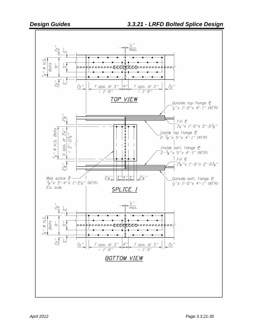
Figure 1
Unfactored Distributed Forces at Splice
Moment (k-ft.) Shear (k) DC1 -7.5 -29.7
DC2 6.5 -4.9
DW 15.7 -11.9
Truck (+Trk+Ln) 831.9 12.0
Truck (-Trk+Ln) -625.1 -68.4
Tandem (+Tan+Ln) 731.5 11.5
Tandem (-Tan+Ln) -506.3 -56.5
2 Trucks -.9(2Trk+Ln) -562.9 N/A
Fatigue (+FATLL+IM) 267.3 4.2
Fatigue (-FATLL+IM) -201.1 -26.8
Construction DC1 -8.5 -31.3
Construction LL+IM -3.9 -4.9
Design Guides 3.3.21 - LRFD Bolted Splice Design
April 2012 Page 3.3.21-37
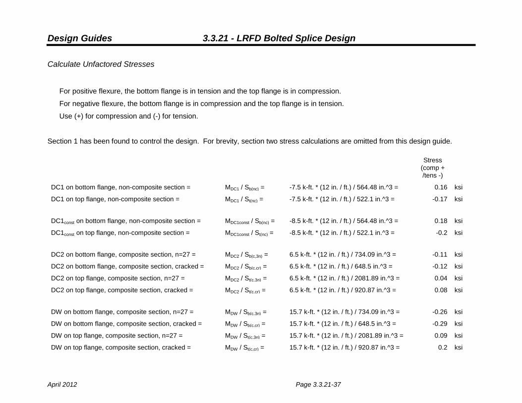
Calculate Unfactored Stresses
For positive flexure, the bottom flange is in tension and the top flange is in compression.
For negative flexure, the bottom flange is in compression and the top flange is in tension.
Use (+) for compression and (-) for tension.
Section 1 has been found to control the design. For brevity, section two stress calculations are omitted from this design guide.
Stress (comp + /tens -)
DC1 on bottom flange, non-composite section = MDC1 / Sb(nc) = -7.5 k-ft. * (12 in. / ft.) / 564.48 in.^3 = 0.16 ksi
DC1 on top flange, non-composite section = MDC1 / St(nc) = -7.5 k-ft. * (12 in. / ft.) / 522.1 in.^3 = -0.17 ksi
DC1const on bottom flange, non-composite section = MDC1const / Sb(nc) = -8.5 k-ft. * (12 in. / ft.) / 564.48 in.^3 = 0.18 ksi
DC1const on top flange, non-composite section = MDC1const / St(nc) = -8.5 k-ft. * (12 in. / ft.) / 522.1 in.^3 = -0.2 ksi
DC2 on bottom flange, composite section, n=27 = MDC2 / Sb(c,3n) = 6.5 k-ft. * (12 in. / ft.) / 734.09 in.^3 = -0.11 ksi
DC2 on bottom flange, composite section, cracked = MDC2 / Sb(c,cr) = 6.5 k-ft. * (12 in. / ft.) / 648.5 in.^3 = -0.12 ksi
DC2 on top flange, composite section, n=27 = MDC2 / St(c,3n) = 6.5 k-ft. * (12 in. / ft.) / 2081.89 in.^3 = 0.04 ksi
DC2 on top flange, composite section, cracked = MDC2 / St(c,cr) = 6.5 k-ft. * (12 in. / ft.) / 920.87 in.^3 = 0.08 ksi
DW on bottom flange, composite section, n=27 = MDW / Sb(c,3n) = 15.7 k-ft. * (12 in. / ft.) / 734.09 in.^3 = -0.26 ksi
DW on bottom flange, composite section, cracked = MDW / Sb(c,cr) = 15.7 k-ft. * (12 in. / ft.) / 648.5 in.^3 = -0.29 ksi
DW on top flange, composite section, n=27 = MDW / St(c,3n) = 15.7 k-ft. * (12 in. / ft.) / 2081.89 in.^3 = 0.09 ksi
DW on top flange, composite section, cracked = MDW / St(c,cr) = 15.7 k-ft. * (12 in. / ft.) / 920.87 in.^3 = 0.2 ksi

Design Guides 3.3.21 - LRFD Bolted Splice Design
Page 3.3.21-38 April 2012
LL+IM+ on bottom flange, composite section, n=9 = MLL+IM+ / Sb(c,n) = 831.9 k-ft. * (12 in. / ft.) / 797.79 in.^3 = -12.51 ksi
LL+IM+ on bottom flange, composite section, cracked = MLL+IM+ / Sb(c,cr) = 831.9 k-ft. * (12 in. / ft.) / 648.5 in.^3 = -15.39 ksi
LL+IM+ on top flange, composite section, n=9 = MLL+IM+ / St(c,n) = 831.9 k-ft. * (12 in. / ft.) / 8027.4 in.^3 = 1.24 ksi
LL+IM+ on top flange, composite section, cracked = MLL+IM+ / St(c,cr) = 831.9 k-ft. * (12 in. / ft.) / 920.87 in.^3 = 10.84 ksi
LL+IM- on bottom flange, composite section, n=9 = MLL+IM- / Sb(c,n) = -625.1 k-ft. * (12 in. / ft.) / 797.79 in.^3 = 9.4 ksi
LL+IM- on bottom flange, composite section, cracked = MLL+IM- / Sb(c,cr) = -625.1 k-ft. * (12 in. / ft.) / 648.5 in.^3 = 11.57 ksi
LL+IM- on top flange, composite section, n=9 = MLL+IM- / St(c,n) = -625.1 k-ft. * (12 in. / ft.) / 8027.4 in.^3 = -0.93 ksi
LL+IM- on top flange, composite section, cracked = MLL+IM- / St(c,cr) = -625.1 k-ft. * (12 in. / ft.) / 920.87 in.^3 = -8.15 ksi
LL+IMconst on bottom flange, non-composite section = MLL+IMconst / Sb(nc) = -3.9 k-ft. * (12 in. / ft.) / 564.48 in.^3 = 0.08 ksi
LL+IMconst on top flange, non-composite section = MLL+IMconst / St(nc) = -3.9 k-ft. * (12 in. / ft.) / 522.1 in.^3 = -0.09 ksi
Fatigue+ on bottom flange, composite section, n=9 = MFAT+ / Sb(c,n) = 267.3 k-ft. * (12 in. / ft.) / 797.79 in.^3 = -4.02 ksi
Fatigue+ on top flange, composite section, n=9 = MFAT+ / St(c,n) = 267.3 k-ft. * (12 in. / ft.) / 8027.4 in.^3 = 0.4 ksi
Fatigue- on bottom flange, composite section, n=9 = MFAT- / Sb(c,n) = -201.1 k-ft. * (12 in. / ft.) / 797.79 in.^3 = 3.02 ksi
Fatigue- on top flange, composite section, n=9 = MFAT- / St(c,n) = -201.1 k-ft. * (12 in. / ft.) / 8027.4 in.^3 = -0.3 ksi

Design Guides 3.3.21 - LRFD Bolted Splice Design
April 2012 Page 3.3.21-39
Calculate Factored Stresses
Section 1 Top Flange: Determine Factored Stresses
Strength I Stresses:
For Strength I loading, the following sections are used:
positive moment negative moment
DC1 non-composite non-composite
DC2 composite, n=27 composite, cracked
DW composite, n=27 composite, cracked
LL+IM composite, n=9 composite, cracked
Positive LL+IM, DW included
1.25DC1 + 1.25DC2 + 1.5DW + 1.75(LL+IM+) 1.25(-0.17 ksi) + 1.25(0.04 ksi) + 1.5(0.09 ksi) + 1.75(1.24 ksi) = 2.14 ksi 0.9DC1 + 0.9DC2 + 1.5DW + 1.75(LL+IM+)
0.9(-0.17 ksi) + 0.9(0.04 ksi) + 1.5(0.09 ksi) + 1.75(1.24 ksi) = 2.19 ksi
1.25DC1 + 1.25DC2 + 0.65DW + 1.75(LL+IM+) 1.25(-0.17 ksi) + 1.25(0.04 ksi) + 0.65(0.09 ksi) + 1.75(1.24 ksi) = 2.07 ksi 0.9DC1 + 0.9DC2 + 0.65DW + 1.75(LL+IM+)
0.9(-0.17 ksi) + 0.9(0.04 ksi) + 0.65(0.09 ksi) + 1.75(1.24 ksi) = 2.11 ksi
Positive LL+IM, DW neglected
1.25DC1 + 1.25DC2 + 1.75(LL+IM+)
1.25(-0.17 ksi) + 1.25(0.04 ksi) + 1.75(1.24 ksi) =
2.01 ksi 0.9DC1 + 0.9DC2 + 1.75(LL+IM+)
0.9(-0.17 ksi) + 0.9(0.04 ksi) + 1.75(1.24 ksi) =
2.05 ksi
Negative LL+IM, DW included
1.25DC1 + 1.25DC2 + 1.5DW + 1.75(LL+IM-) 1.25(-0.17 ksi) + 1.25(0.04 ksi) + 1.5(0.09 ksi) + 1.75(-8.15 ksi) = -14.29 ksi 0.9DC1 + 0.9DC2 + 1.5DW + 1.75(LL+IM-)
0.9(-0.17 ksi) + 0.9(0.04 ksi) + 1.5(0.09 ksi) + 1.75(-8.15 ksi) = -14.24 ksi
1.25DC1 + 1.25DC2 + 0.65DW + 1.75(LL+IM-) 1.25(-0.17 ksi) + 1.25(0.04 ksi) + 0.65(0.09 ksi) + 1.75(-8.15 ksi) = -14.37 ksi 0.9DC1 + 0.9DC2 + 0.65DW + 1.75(LL+IM-)
0.9(-0.17 ksi) + 0.9(0.04 ksi) + 0.65(0.09 ksi) + 1.75(-8.15 ksi) = -14.32 ksi

Design Guides 3.3.21 - LRFD Bolted Splice Design
Page 3.3.21-40 April 2012
Negative LL+IM, DW neglected 1.25DC1 + 1.25DC2 + 1.75(LL+IM-)
1.25(-0.17 ksi) + 1.25(0.04 ksi) + 1.75(-8.15 ksi) =
-14.43 ksi
0.9DC1 + 0.9DC2 + 1.75(LL+IM-)
0.9(-0.17 ksi) + 0.9(0.04 ksi) + 1.75(-8.15 ksi) =
-14.38 ksi
Constructability 1.25DC1 + 1.75(LL+IMConst)
1.25(-0.2 ksi) + 1.75(-0.09 ksi) =
-0.41 ksi
Service II Stresses:
For Service II loading, if the amount of stress in the deck does not exceed 2fr then an uncracked section may be used in the negative
moment region. Note that for calculation of deck stresses, the section modulus used should be that for the composite section transformed to concrete, not the composite section transformed to steel. As the composite section transformed to concrete = n * Stslab(c,n), it is written that way in the equation below. The stresses for DC2 and DW act in the opposite direction to the LL+IM stresses and have been conservatively neglected.
fr = 0.24(f'c)0.5
(5.4.2.6) = 0.24 * (3.5 ksi)^0.5
= 0.45 ksi
2fr = 0.9 ksi
1.3MLL+IM- / (9 * Stslab(c,n)) =
1.3(-625.1 k-ft. * (12 in. / ft.)) / (9 * 2312.32 in.^3) = -0.47 ksi
Uncracked sections should be used.
positive moment negative moment
DC1 non-composite non-composite
DC2 composite, n=27 composite, n=27
DW composite, n=27 composite, n=27
LL+IM composite, n=9 composite, n=9
Design Guides 3.3.21 - LRFD Bolted Splice Design
April 2012 Page 3.3.21-41
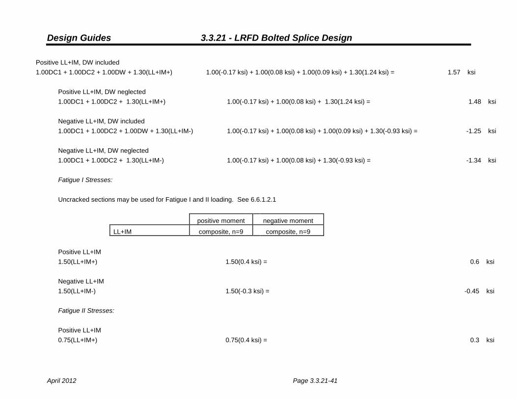
Positive LL+IM, DW included 1.00DC1 + 1.00DC2 + 1.00DW + 1.30(LL+IM+) 1.00(-0.17 ksi) + 1.00(0.08 ksi) + 1.00(0.09 ksi) + 1.30(1.24 ksi) = 1.57 ksi
Positive LL+IM, DW neglected 1.00DC1 + 1.00DC2 + 1.30(LL+IM+) 1.00(-0.17 ksi) + 1.00(0.08 ksi) + 1.30(1.24 ksi) = 1.48 ksi Negative LL+IM, DW included 1.00DC1 + 1.00DC2 + 1.00DW + 1.30(LL+IM-) 1.00(-0.17 ksi) + 1.00(0.08 ksi) + 1.00(0.09 ksi) + 1.30(-0.93 ksi) = -1.25 ksi Negative LL+IM, DW neglected 1.00DC1 + 1.00DC2 + 1.30(LL+IM-) 1.00(-0.17 ksi) + 1.00(0.08 ksi) + 1.30(-0.93 ksi) = -1.34 ksi Fatigue I Stresses: Uncracked sections may be used for Fatigue I and II loading. See 6.6.1.2.1
positive moment negative moment
LL+IM composite, n=9 composite, n=9 Positive LL+IM 1.50(LL+IM+) 1.50(0.4 ksi) = 0.6 ksi Negative LL+IM 1.50(LL+IM-) 1.50(-0.3 ksi) = -0.45 ksi Fatigue II Stresses: Positive LL+IM 0.75(LL+IM+) 0.75(0.4 ksi) = 0.3 ksi

Design Guides 3.3.21 - LRFD Bolted Splice Design
Page 3.3.21-42 April 2012
Negative LL+IM 0.75(LL+IM-) 0.75(-0.3 ksi) = -0.23 ksi
Section 1 Bottom Flange: Determine Factored Stresses
Strength I Stresses:
For Strength I loading, the following sections are used:
positive moment negative moment
DC1 non-composite non-composite
DC2 composite, n=27 composite, cracked
DW composite, n=27 composite, cracked
LL+IM composite, n=9 composite, cracked
Positive LL+IM, DW included
1.25DC1 + 1.25DC2 + 1.5DW + 1.75(LL+IM+) 1.25(0.16 ksi) + 1.25(-0.11 ksi) + 1.5(-0.26 ksi) + 1.75(-12.51 ksi) = -22.22 ksi 0.9DC1 + 0.9DC2 + 1.5DW + 1.75(LL+IM+)
0.9(0.16 ksi) + 0.9(-0.11 ksi) + 1.5(-0.26 ksi) + 1.75(-12.51 ksi) = -22.24 ksi
1.25DC1 + 1.25DC2 + 0.65DW + 1.75(LL+IM+) 1.25(0.16 ksi) + 1.25(-0.11 ksi) + 0.65(-0.26 ksi) + 1.75(-12.51 ksi) = -22 ksi 0.9DC1 + 0.9DC2 + 0.65DW + 1.75(LL+IM+)
0.9(0.16 ksi) + 0.9(-0.11 ksi) + 0.65(-0.26 ksi) + 1.75(-12.51 ksi) = -22.02 ksi
Positive LL+IM, DW neglected
1.25DC1 + 1.25DC2 + 1.75(LL+IM+)
1.25(0.16 ksi) + 1.25(-0.11 ksi) + 1.75(-12.51 ksi) =
-21.83 ksi 0.9DC1 + 0.9DC2 + 1.75(LL+IM+)
0.9(0.16 ksi) + 0.9(-0.11 ksi) + 1.75(-12.51 ksi) =
-21.85 ksi
Negative LL+IM, DW included
1.25DC1 + 1.25DC2 + 1.5DW + 1.75(LL+IM-) 1.25(0.16 ksi) + 1.25(-0.11 ksi) + 1.5(-0.26 ksi) + 1.75(11.57 ksi) = 19.92 ksi 0.9DC1 + 0.9DC2 + 1.5DW + 1.75(LL+IM-)
0.9(0.16 ksi) + 0.9(-0.11 ksi) + 1.5(-0.26 ksi) + 1.75(11.57 ksi) = 19.9 ksi
1.25DC1 + 1.25DC2 + 0.65DW + 1.75(LL+IM-) 1.25(0.16 ksi) + 1.25(-0.11 ksi) + 0.65(-0.26 ksi) + 1.75(11.57 ksi) = 20.14 ksi

Design Guides 3.3.21 - LRFD Bolted Splice Design
April 2012 Page 3.3.21-43
0.9DC1 + 0.9DC2 + 0.65DW + 1.75(LL+IM-)
0.9(0.16 ksi) + 0.9(-0.11 ksi) + 0.65(-0.26 ksi) + 1.75(11.57 ksi) = 20.12 ksi
Negative LL+IM, DW neglected 1.25DC1 + 1.25DC2 + 1.75(LL+IM-)
1.25(0.16 ksi) + 1.25(-0.11 ksi) + 1.75(11.57 ksi) =
20.31 ksi 0.9DC1 + 0.9DC2 + 1.75(LL+IM-)
0.9(0.16 ksi) + 0.9(-0.11 ksi) + 1.75(11.57 ksi) =
20.29 ksi
Constructability
1.25DC1 + 1.75(LL+IMConst)
1.25(0.18 ksi) + 1.75(0.08 ksi) =
0.37 ksi
Service II Stresses:
positive moment negative moment
DC1 non-composite non-composite
DC2 composite, n=27 composite, n=27
DW composite, n=27 composite, n=27
LL+IM composite, n=9 composite, n=9
Positive LL+IM, DW included
1.00DC1 + 1.00DC2 + 1.00DW + 1.30(LL+IM+) 1.00(0.16 ksi) + 1.00(-0.12 ksi) + 1.00(-0.26 ksi) + 1.30(-12.51 ksi) = -16.47 ksi
Positive LL+IM, DW neglected 1.00DC1 + 1.00DC2 + 1.30(LL+IM+)
1.00(0.16 ksi) + 1.00(-0.12 ksi) + 1.30(-12.51 ksi) =
-16.21 ksi
Negative LL+IM, DW included
1.00DC1 + 1.00DC2 + 1.00DW + 1.30(LL+IM-) 1.00(0.16 ksi) + 1.00(-0.12 ksi) + 1.00(-0.26 ksi) + 1.30(9.4 ksi) = 12.01 ksi
Negative LL+IM, DW neglected 1.00DC1 + 1.00DC2 + 1.30(LL+IM-)
1.00(0.16 ksi) + 1.00(-0.12 ksi) + 1.30(9.4 ksi) =
12.27 ksi

Design Guides 3.3.21 - LRFD Bolted Splice Design
Page 3.3.21-44 April 2012
Fatigue I Stresses:
Uncracked sections may be used for Fatigue I and II loading. See 6.6.1.2.1
positive moment negative moment
LL+IM composite, n=9 composite, n=9
Positive LL+IM 1.50(LL+IM+)
1.50(-4.02 ksi) =
-6.03 ksi
Negative LL+IM 1.50(LL+IM-)
1.50(3.02 ksi) =
4.53 ksi
Fatigue II Stresses:
Positive LL+IM 0.75(LL+IM+)
0.75(-4.02 ksi) =
-3.02 ksi
Negative LL+IM 0.75(LL+IM-)
0.75(3.02 ksi) =
2.27 ksi

Design Guides 3.3.21 - LRFD Bolted Splice Design
April 2012 Page 3.3.21-45
RESULTS:
Section 1 Top Flange max
Section 2 Top Flange max
Section 1 Top Flange min
Section 2 Top Flange min
Section 1 Bottom Flange max
Section 2 Bottom Flange max
Section 1 Bottom Flange min
Section 2 Bottom Flange min
STRENGTH I 2.19 2.5 -14.43 -7.14 20.31 7.54 -22.24 -8.82 ksi SERVICE II 1.57 1.85 -1.34 -1.41 12.27 5.48 -16.47 -7.38 ksi FATIGUE I
0.6 0.68 -0.45 -0.51 4.53 1.8 -6.03 -2.39 ksi
FATIGUE II 0.3 0.34 -0.23 -0.26 2.27 0.9 -3.02 -1.19 ksi CONSTRUCTION -0.41 0.2
0.37 -0.18
ksi
Note that construction loading clearly does not control the design of the splice.

Design Guides 3.3.21 - LRFD Bolted Splice Design
Page 3.3.21-46 April 2012
Determine Trial Flange Splice Plates
Bottom Flange Splice Plate
Try 12 in. x 0.5 in. plate for outside plate, 5 in. x 0.625 in. plates for inside plates
Top Flange Splice Plate
Try 12 in. x 0.5 in. plate for outside plate, 5 in. x 0.625 in. plates for inside plates
Note that these plates have a capacity well above the required capacity. However, 0.5 in. is
the thinnest plate allowed for a flange, and the inside plates must be slightly thicker in order
to make the areas of the outside plate and inside plates within 10% of each other.
Also note that although the top flange and bottom flange of the girders are slightly different
in size, this splice is symmetric (i.e. the top flange plates and bolts are congruent with the
bottom flange plates and bolts). As such, some of the calculations have been omitted for
brevity.
Determine Trial Flange Splice Plate Bolt Layout
Bottom Flange Splice Plate
Try four staggered rows of bolts spaced as shown in Figure 1.
Top Flange Splice Plate
Try four staggered rows of bolts spaced as shown in Figure 1.
Calculate Flange Effective Area, Ae (6.13.6.1.4c)
As this splice is in an area of stress reversal, both flanges can be in either tension or
compression.

Design Guides 3.3.21 - LRFD Bolted Splice Design
April 2012 Page 3.3.21-47
Assuming top flange in tension:
Ae = gnyty
uu AAFF
≤
φφ
(Eq. 6.13.6.1.4c-2)
Where:
φu = 0.80 (6.5.4.2)
Fu = 65 ksi
φy = 0.95 (6.5.4.2)
Fyt = 50 ksi
An = Wnt. As the bolt layout is staggered, there are two possible failure planes that
could define Wn. The first is a straight-line failure across two of the bolt
holes, which would have a shorter, more direct plate area but less hole
subtractions. The second is a staggered failure across four of the bolt holes,
which would have a larger indirect plate area but more hole subtractions. By
inspection, the first failure plane will control the design.
= bf – dhole(# of holes)
Where:
bf = 12 in.
dhole = 0.9375 in. (Table 6.13.2.4.2-1)
An = [12 in. – 2(0.9375 in.)](0.75 in.) = 7.59 in.2
Ae = ( )( )( )( ) ( )2.in59.7
ksi5095.0ksi658.0
= 8.31 in.2
Ag = (12 in.)(0.75 in.) = 9 in.2
8.31 in.2 controls.
Assuming top flange in compression:
Ae = Ag = 9 in.2
Assuming bottom flange in tension:
Ae = gnyty
uu AAFF
≤
φφ
(Eq. 6.13.6.1.4c-2)
Design Guides 3.3.21 - LRFD Bolted Splice Design
Page 3.3.21-48 April 2012
Where:
φu = 0.80 (6.5.4.2)
Fu = 65 ksi
φy = 0.95 (6.5.4.2)
Fyt = 50 ksi
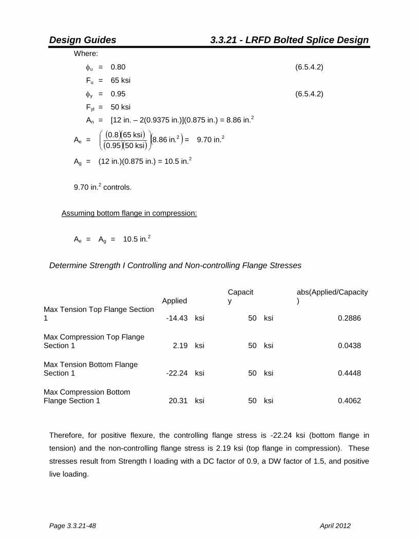
An = [12 in. – 2(0.9375 in.)](0.875 in.) = 8.86 in.2
Ae = ( )( )( )( ) ( )2.in86.8
ksi5095.0ksi658.0
= 9.70 in.2
Ag = (12 in.)(0.875 in.) = 10.5 in.2
9.70 in.2 controls.
Assuming bottom flange in compression:
Ae = Ag = 10.5 in.2
Determine Strength I Controlling and Non-controlling Flange Stresses
Applied
Capacity
abs(Applied/Capacity)
Max Tension Top Flange Section 1 -14.43 ksi 50 ksi 0.2886
Max Compression Top Flange Section 1 2.19 ksi 50 ksi 0.0438
Max Tension Bottom Flange Section 1 -22.24 ksi 50 ksi 0.4448
Max Compression Bottom Flange Section 1 20.31 ksi 50 ksi 0.4062
Therefore, for positive flexure, the controlling flange stress is -22.24 ksi (bottom flange in
tension) and the non-controlling flange stress is 2.19 ksi (top flange in compression). These
stresses result from Strength I loading with a DC factor of 0.9, a DW factor of 1.5, and positive
live loading.
Design Guides 3.3.21 - LRFD Bolted Splice Design
April 2012 Page 3.3.21-49
For negative flexure, the controlling flange stress is 20.31 ksi (bottom flange in compression)
and the non-controlling flange stress is -14.43 ksi (top flange in tension). These stresses result
from Strength I loading with a DC factor of 1.25, DW neglected, and negative live loading.
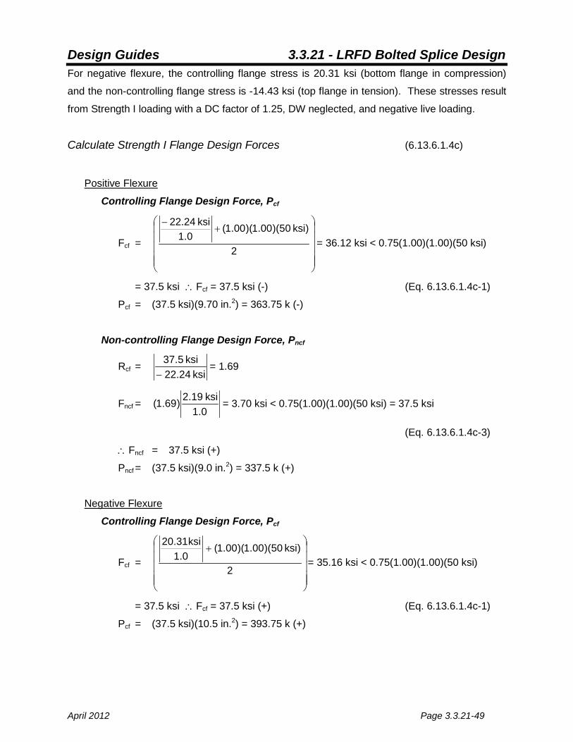
Calculate Strength I Flange Design Forces (6.13.6.1.4c)
Positive Flexure
Controlling Flange Design Force, Pcf
Fcf =
+
−
2
)ksi 50)(00.1)(00.1(0.1
ksi 22.24
= 36.12 ksi < 0.75(1.00)(1.00)(50 ksi)
= 37.5 ksi ∴Fcf = 37.5 ksi (-) (Eq. 6.13.6.1.4c-1)
Pcf = (37.5 ksi)(9.70 in.2) = 363.75 k (-)
Non-controlling Flange Design Force, Pncf
Rcf = ksi 22.24
ksi 5.37−
= 1.69
Fncf = 0.1ksi19.2)69.1( = 3.70 ksi < 0.75(1.00)(1.00)(50 ksi) = 37.5 ksi
(Eq. 6.13.6.1.4c-3)
∴Fncf = 37.5 ksi (+)
Pncf = (37.5 ksi)(9.0 in.2) = 337.5 k (+)
Negative Flexure
Controlling Flange Design Force, Pcf
Fcf =
+
2
)ksi 50)(00.1)(00.1(0.1
ksi 31.02
= 35.16 ksi < 0.75(1.00)(1.00)(50 ksi)
= 37.5 ksi ∴Fcf = 37.5 ksi (+) (Eq. 6.13.6.1.4c-1)
Pcf = (37.5 ksi)(10.5 in.2) = 393.75 k (+)

Design Guides 3.3.21 - LRFD Bolted Splice Design
Page 3.3.21-50 April 2012
Non-controlling Flange Design Force, Pncf
Rcf = ksi 0.312ksi 5.37− = 1.85
Fncf = 0.1
ksi43.14)85.1( −= 26.7 ksi < 0.75(1.00)(1.00)(50 ksi) = 37.5 ksi
(Eq. 6.13.6.1.4c-3)
∴Fcf = 37.5 ksi (-)
Pncf = (37.5 ksi)(8.31 in.2) = 311.63 k (-)
Check Flange Splice Plate Strength
Check Tension in Splice Plates (6.13.6.1.4c & 6.13.5.2)
Positive Flexure The bottom plate is in tension in positive flexure.
Check yielding on the gross section:
Pr = φyPny = φyFyAg > Pcf or Pncf as applicable (Eq. 6.8.2.1-1)
Where:
φy = 0.95 (6.5.4.2)
Fy = 50 ksi
Ag = (12 in.)(0.5 in.) + 2(5 in.)(0.625 in) = 12.25 in.2
Pr = (0.95)(50 ksi)(12.25 in.2) = 581.88 k > 363.75 k O.K.
Check fracture on the net section:
Pr = φuPnu = φuFuAnRpU > Pcf or Pncf as applicable (Eq. 6.8.2.1-2)
Where:
φu = 0.80 (6.5.4.2)
Fu = 65 ksi
An = [12 in. – 2(0.9375 in.)](0.5 in.) + 2(5 in. – 0.9375 in.)(0.625 in.)
Design Guides 3.3.21 - LRFD Bolted Splice Design
April 2012 Page 3.3.21-51
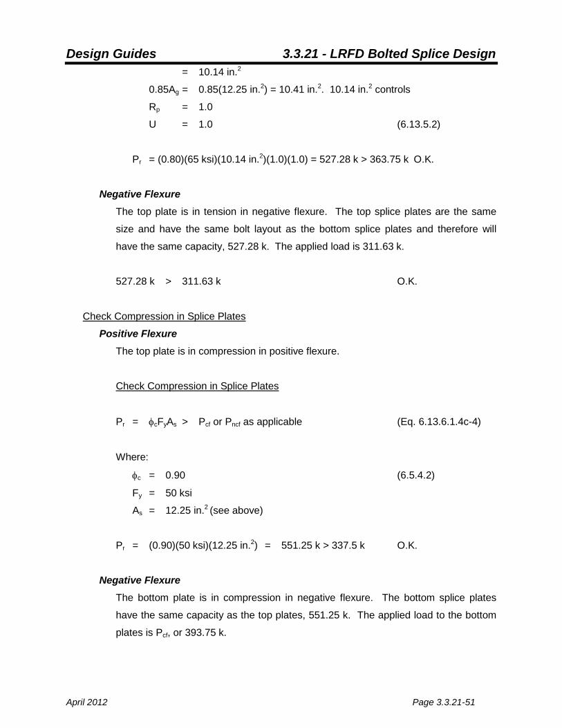
= 10.14 in.2
0.85Ag = 0.85(12.25 in.2) = 10.41 in.2. 10.14 in.2 controls
Rp = 1.0
U = 1.0 (6.13.5.2)
Pr = (0.80)(65 ksi)(10.14 in.2)(1.0)(1.0) = 527.28 k > 363.75 k O.K.
Negative Flexure The top plate is in tension in negative flexure. The top splice plates are the same
size and have the same bolt layout as the bottom splice plates and therefore will
have the same capacity, 527.28 k. The applied load is 311.63 k.
527.28 k > 311.63 k O.K.
Check Compression in Splice Plates
Positive Flexure The top plate is in compression in positive flexure.
Check Compression in Splice Plates
Pr = φcFyAs > Pcf or Pncf as applicable (Eq. 6.13.6.1.4c-4)
Where:
φc = 0.90 (6.5.4.2)
Fy = 50 ksi
As = 12.25 in.2 (see above)
Pr = (0.90)(50 ksi)(12.25 in.2) = 551.25 k > 337.5 k O.K.
Negative Flexure The bottom plate is in compression in negative flexure. The bottom splice plates
have the same capacity as the top plates, 551.25 k. The applied load to the bottom
plates is Pcf, or 393.75 k.

Design Guides 3.3.21 - LRFD Bolted Splice Design
Page 3.3.21-52 April 2012
551.25 k > 393.75 k O.K.
Check Flange Splice Plate Fatigue (6.6.1.2.2)
The bottom flange has higher fatigue stresses. Check bottom flange for fatigue, and if
OK, assume top flange also OK.
Use Fatigue Category B for bolted splices. (Table 6.6.1.2.3-1)
The following design criteria shall be met:
n)F()f( ∆≤∆γ (Eq. 6.6.1.2.2-1)
Where:
γ = load factor, taken as 1.5 for Fatigue I loading and 0.75 for Fatigue II
loading. Determine whether Fatigue I or Fatigue II load factors are
appropriate:
ADTT = ( )5.0day
trucks300years20years57
daytrucks300
daytrucks600
+
−
= 713 trucks/day
p = 1.0 for one lane (not counting shoulders) (Table 3.6.1.4.2-1)
(ADTT)SL = 1.0(713 trucks/day) = 713 trucks/day
The limit for infinite life for Fatigue Category B is 860 trucks/day (see Table
6.6.1.2.3-2). Therefore, use finite life (Fatigue II) loading.
)f( r∆ = PL
efatefat
AA)f(A)f( −+ −
Where: +γ fatf = -3.02 ksi
−γ fatf = 2.27 ksi
Design Guides 3.3.21 - LRFD Bolted Splice Design
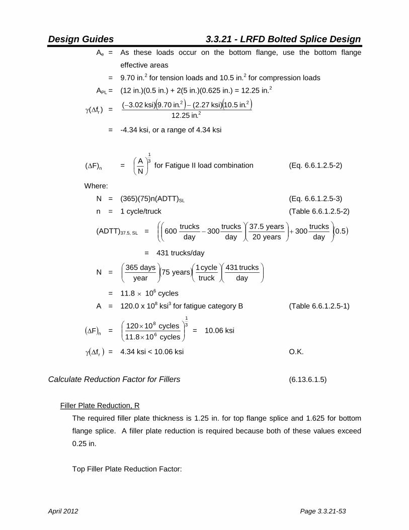
April 2012 Page 3.3.21-53
Ae = As these loads occur on the bottom flange, use the bottom flange
effective areas
= 9.70 in.2 for tension loads and 10.5 in.2 for compression loads
APL = (12 in.)(0.5 in.) + 2(5 in.)(0.625 in.) = 12.25 in.2
)f( r∆γ = ( ) ( )2
22
.in25.12.in5.10)ksi27.2(.in70.9)ksi02.3( −−
= -4.34 ksi, or a range of 4.34 ksi
n)F(∆ = 31
NA
for Fatigue II load combination (Eq. 6.6.1.2.5-2)
Where:
N = (365)(75)n(ADTT)SL (Eq. 6.6.1.2.5-3)
n = 1 cycle/truck (Table 6.6.1.2.5-2)
(ADTT)37.5, SL = ( )5.0day
trucks300years20years5.37
daytrucks300
daytrucks600
+
−
= 431 trucks/day
N = ( )
daytrucks431
truckcycle1years75
yeardays365
= 11.8 × 10⁶ cycles
A = 120.0 x 10⁸ ksi3 for fatigue category B (Table 6.6.1.2.5-1)
( )nF∆ = 31
6
8
cycles108.11cycles10120
××
= 10.06 ksi
( )rf∆γ = 4.34 ksi < 10.06 ksi O.K.
Calculate Reduction Factor for Fillers (6.13.6.1.5)
Filler Plate Reduction, R
The required filler plate thickness is 1.25 in. for top flange splice and 1.625 for bottom
flange splice. A filler plate reduction is required because both of these values exceed
0.25 in.
Top Filler Plate Reduction Factor:

Design Guides 3.3.21 - LRFD Bolted Splice Design
Page 3.3.21-54 April 2012
Af = (12 in.)(1.25 in.) = 15.0 in.2
Ap = 12.25 in.2 (see above) > Atf = (12 in.)(0.75 in.) = 9.0 in.2 ∴Ap = 9.0 in.2
γ = 2
2
.in .09.in 0.15 = 1.67
R = ( )
+
+)67.121(
)67.11( = 0.62
Bottom Filler Plate Reduction Factor:
Af = (12 in.)(1.625 in.) = 19.5 in.2
Ap = 12.25 in.2 > (12 in.)(0.875 in.) = 10.5 in.2
∴Ap = 10.5 in.2
γ = 2
2
.in 0.51
.in 5.19 = 1.86
R = ( )
+
+)86.121(
)86.11( = 0.61
Check Flange Splice Bolt Shear Strength
Calculate Factored Shear Resistance for Bolts, Rr (6.13.2.7)
Bottom Flange:
Rr = φsRnR
Where:
φs = 0.80 (6.5.4.2)
R = 0.62 for top plates, 0.61 for bottom plates. Use 0.61 for simplicity.
Rn = 0.38AbFubNs(assumes threads are on the shear plane) (Eq. 6.13.2.7-2)
Where:
Ab = 0.25(π)(0.875 in.)2 = 0.60 in.2

Design Guides 3.3.21 - LRFD Bolted Splice Design
April 2012 Page 3.3.21-55
Fub = 120 ksi (6.4.3)
Ns = 2
Rn = 0.38(0.60 in.2)(120 ksi)(2) = 54.7 k / bolt
Rr = (0.80)(54.7 k / bolt)(0.61) = 26.7 k / bolt
Pr =
bolts 16k 75.393 = 24.6 kips per bolt < 26.7 kips per bolt O.K.
The top flange bolts have the same capacity, but a lower applied load and are OK by
inspection.
Check Flange Splice Bolt Slip Resistance
Bottom Flange:
Rr > Pslip
Where:
Rr = Rn (Eq. 6.13.2.2-1)
Where:
Rn = KhKsNsPt (Eq. 6.13.2.8-1)
Kh = 1 (Table 6.13.2.8-2)
Ks = 0.33 (Table 6.13.2.8-3)
Ns = 2
Pt = 39 k / bolt (Table 6.13.2.8-1)
Rr = Rn = (1)(0.33)(2)(39 k / bolt) = 25.7 k / bolt
Pslip = b
sliptot
NP −
Where:
Ptot-slip = FsAg

Design Guides 3.3.21 - LRFD Bolted Splice Design
Page 3.3.21-56 April 2012
Fs = h
s
Rf
(Eq. 6.13.6.1.4c-5)
Where:
fs = -16.47 ksi
Rh = 1.0 (6.10.1.10.1)
Fs = 0.1
ksi47.16− = 16.47 ksi
Ag = 10.5 in.2
Ptot-slip = (16.47 ksi)(10.5 in.2) = 172.94 k
Nb = 16 bolts
Pslip = bolts16
k94.172 = 10.8 k / bolt < 25.7 k / bolt O.K.
The top flange has the same bolt slip capacity but lower loads, and is O.K. by inspection.
Check Flange Splice Bearing Resistance
Verify Pbrg ≤ Rr for both flange splices for positive and negative flexure.
Where:
Pbrg = b
ncfcf
NP or P
= bolts16
k75.393= 24.6 k / bolt
Rr = φbbRn
Where:
φbb = 0.80 (6.5.4.2)
Rn = nominal resistance of interior and end bolt holes (kips)
If xclear ≥ 2.0d and xend ≥ 2.0d:
Rn = 2.4dtFu (Eq. 6.13.2.9-1)
If xclear < 2.0d or xend < 2.0d:
Rn = 1.2LctFu (Eq. 6.13.2.9-2)
Where:
Design Guides 3.3.21 - LRFD Bolted Splice Design
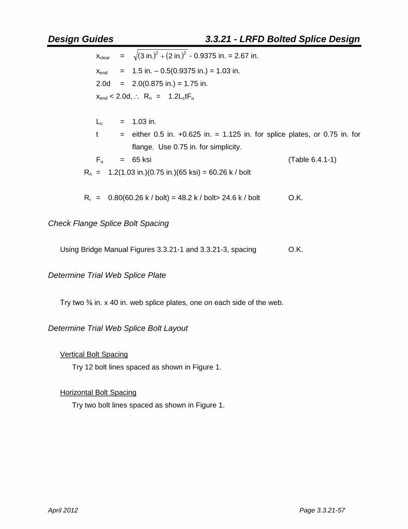
April 2012 Page 3.3.21-57
xclear = ( ) ( )22 .in2.in3 + - 0.9375 in. = 2.67 in.
xend = 1.5 in. – 0.5(0.9375 in.) = 1.03 in.
2.0d = 2.0(0.875 in.) = 1.75 in.
xend < 2.0d, ∴ Rn = 1.2LctFu
Lc = 1.03 in.
t = either 0.5 in. +0.625 in. = 1.125 in. for splice plates, or 0.75 in. for
flange. Use 0.75 in. for simplicity.
Fu = 65 ksi (Table 6.4.1-1)
Rn = 1.2(1.03 in.)(0.75 in.)(65 ksi) = 60.26 k / bolt
Rr = 0.80(60.26 k / bolt) = 48.2 k / bolt> 24.6 k / bolt O.K.
Check Flange Splice Bolt Spacing
Using Bridge Manual Figures 3.3.21-1 and 3.3.21-3, spacing O.K.
Determine Trial Web Splice Plate
Try two ⅜ in. x 40 in. web splice plates, one on each side of the web.
Determine Trial Web Splice Bolt Layout
Vertical Bolt Spacing
Try 12 bolt lines spaced as shown in Figure 1.
Horizontal Bolt Spacing
Try two bolt lines spaced as shown in Figure 1.
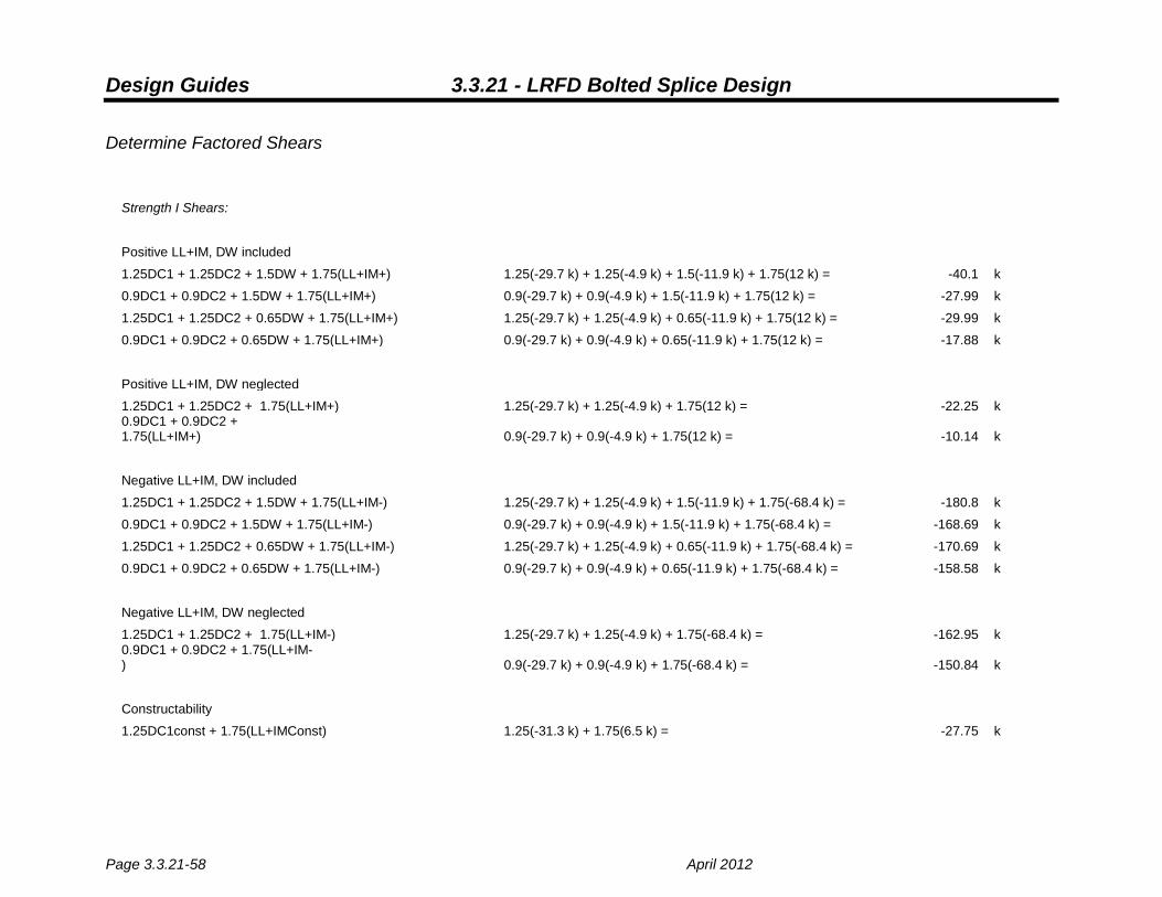
Design Guides 3.3.21 - LRFD Bolted Splice Design
Page 3.3.21-58 April 2012
Determine Factored Shears
Strength I Shears:
Positive LL+IM, DW included 1.25DC1 + 1.25DC2 + 1.5DW + 1.75(LL+IM+) 1.25(-29.7 k) + 1.25(-4.9 k) + 1.5(-11.9 k) + 1.75(12 k) = -40.1 k
0.9DC1 + 0.9DC2 + 1.5DW + 1.75(LL+IM+)
0.9(-29.7 k) + 0.9(-4.9 k) + 1.5(-11.9 k) + 1.75(12 k) =
-27.99 k
1.25DC1 + 1.25DC2 + 0.65DW + 1.75(LL+IM+) 1.25(-29.7 k) + 1.25(-4.9 k) + 0.65(-11.9 k) + 1.75(12 k) = -29.99 k
0.9DC1 + 0.9DC2 + 0.65DW + 1.75(LL+IM+)
0.9(-29.7 k) + 0.9(-4.9 k) + 0.65(-11.9 k) + 1.75(12 k) =
-17.88 k
Positive LL+IM, DW neglected 1.25DC1 + 1.25DC2 + 1.75(LL+IM+)
1.25(-29.7 k) + 1.25(-4.9 k) + 1.75(12 k) =
-22.25 k
0.9DC1 + 0.9DC2 + 1.75(LL+IM+)
0.9(-29.7 k) + 0.9(-4.9 k) + 1.75(12 k) =
-10.14 k
Negative LL+IM, DW included 1.25DC1 + 1.25DC2 + 1.5DW + 1.75(LL+IM-) 1.25(-29.7 k) + 1.25(-4.9 k) + 1.5(-11.9 k) + 1.75(-68.4 k) = -180.8 k
0.9DC1 + 0.9DC2 + 1.5DW + 1.75(LL+IM-)
0.9(-29.7 k) + 0.9(-4.9 k) + 1.5(-11.9 k) + 1.75(-68.4 k) = -168.69 k
1.25DC1 + 1.25DC2 + 0.65DW + 1.75(LL+IM-) 1.25(-29.7 k) + 1.25(-4.9 k) + 0.65(-11.9 k) + 1.75(-68.4 k) = -170.69 k
0.9DC1 + 0.9DC2 + 0.65DW + 1.75(LL+IM-)
0.9(-29.7 k) + 0.9(-4.9 k) + 0.65(-11.9 k) + 1.75(-68.4 k) = -158.58 k
Negative LL+IM, DW neglected 1.25DC1 + 1.25DC2 + 1.75(LL+IM-)
1.25(-29.7 k) + 1.25(-4.9 k) + 1.75(-68.4 k) =
-162.95 k 0.9DC1 + 0.9DC2 + 1.75(LL+IM-)
0.9(-29.7 k) + 0.9(-4.9 k) + 1.75(-68.4 k) =
-150.84 k
Constructability 1.25DC1const + 1.75(LL+IMConst)
1.25(-31.3 k) + 1.75(6.5 k) =
-27.75 k
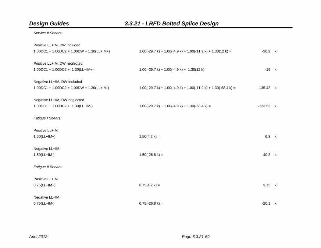
Design Guides 3.3.21 - LRFD Bolted Splice Design
April 2012 Page 3.3.21-59
Service II Shears:
Positive LL+IM, DW included 1.00DC1 + 1.00DC2 + 1.00DW + 1.30(LL+IM+) 1.00(-29.7 k) + 1.00(-4.9 k) + 1.00(-11.9 k) + 1.30(12 k) = -30.9 k
Positive LL+IM, DW neglected 1.00DC1 + 1.00DC2 + 1.30(LL+IM+)
1.00(-29.7 k) + 1.00(-4.9 k) + 1.30(12 k) =
-19 k
Negative LL+IM, DW included 1.00DC1 + 1.00DC2 + 1.00DW + 1.30(LL+IM-) 1.00(-29.7 k) + 1.00(-4.9 k) + 1.00(-11.9 k) + 1.30(-68.4 k) = -135.42 k
Negative LL+IM, DW neglected 1.00DC1 + 1.00DC2 + 1.30(LL+IM-)
1.00(-29.7 k) + 1.00(-4.9 k) + 1.30(-68.4 k) =
-123.52 k
Fatigue I Shears:
Positive LL+IM 1.50(LL+IM+)
1.50(4.2 k) =
6.3 k
Negative LL+IM 1.50(LL+IM-)
1.50(-26.8 k) =
-40.2 k
Fatigue II Shears:
Positive LL+IM 0.75(LL+IM+)
0.75(4.2 k) =
3.15 k
Negative LL+IM 0.75(LL+IM-)
0.75(-26.8 k) =
-20.1 k

Design Guides 3.3.21 - LRFD Bolted Splice Design
Page 3.3.21-60 April 2012
Check Web Splice Plate Strength
Calculate Nominal Web Shear Resistance
Vu ≤ φvVn (Eq. 6.10.9.1-1)
Where:
φv = 1.00 (6.5.4.2)
Vu = 180.89 k
Vn = CVp for unstiffened webs. Assume web is unstiffened. (Eq. 6.10.9.2-1)
Where:
wtD
= 96
ywFEk12.1 =
)ksi50()5)(ksi29000(12.1 = 60.3
ywFEk40.1 =
)ksi50()5)(ksi29000(40.1 = 75.4
∴ C =
yw2
w
FEk
tD
57.1 (Eq. 6.10.9.3.2-6)
= ( )( )
ksi505ksi29000
.in4375.0.in42
57.12
= 0.49
Vp = 0.58FywDtw (Eq. 6.10.9.2-2)
= 0.58(50 ksi)(42 in.)(0.4375 in.)
= 532.9 k
CVp = 0.49(532.9 k) = 261.1 k

Design Guides 3.3.21 - LRFD Bolted Splice Design
April 2012 Page 3.3.21-61
Calculate Strength I Flexural Stress for Web Splice Plates
fSTRENGTH I = PL
uw
PL
uwuv
AH
SMM
++
Where:
SPL = ( )( )
6.in40.in375.02 2
= 200 in.3
APL = 2(0.375 in.)(40 in.) = 30 in.2
Calculate Muv, the Moment due to Shear Eccentricity Muv = Vuwe
Where:
e = 3.5 in.
Vuw = 1.5Vu if Vu < 0.5φvVn (Eq. 6.13.6.1.4b-1)
= ( )
2VV nvu φ+
otherwise (Eq. 6.13.6.1.4b-2)
Where:
Vu = 180.8 k
φv = 1.00 (6.5.4.2)
0.5φvVn = 0.5(1.00)(261.1 k) = 130.55 k < 180.8 k
∴Vuw = ( )( )2
k1.26100.1k8.180 +
= 221.0 k
Muv = (221.0 k)(3.5 in.) = 773.5 k-in.
Calculate Muw, the Moment Resisted by the Web (Assuming a Symmetric Stress Diagram)
Muw must be calculated for both positive and negative flexure to determine which
case controls.

Design Guides 3.3.21 - LRFD Bolted Splice Design
Page 3.3.21-62 April 2012
Muw = ncfcfcfh
2w fRFR12Dt
− (C6.13.6.1.4b-1)
Where for positive flexure:
tw = 0.4375 in.
D = 42 in.
Rh = 1.0 (6.10.1.10.1)
Fcf = -37.5 ksi
fncf = 2.19 ksi
fcf = -22.24 ksi
Rcf = ksi24.22
ksi5.37−
= 1.69
Muw = ( )( ) ( )( ) ( )( )ksi19.269.1ksi5.370.112
.in42.in4375.0 2
−−
= 2649.75 k-in.
For negative flexure:
tw = 0.4375 in.
D = 42 in.
Rh = 1.0 (6.10.1.10.1)
Fcf = 37.5 ksi
fncf = -14.43 ksi
fcf = 20.31 ksi
Rcf = ksi31.20ksi5.37 = 1.85
Muw = ( )( ) ( )( ) ( )( )ksi43.1485.1ksi5.370.112
.in42.in4375.0 2
−−
= 4128.57 k-in.
Calculate Huw, the Additional Force Due to Non-Symmetry of Stress Diagram
To be consistent with Muw, Huw also must be calculated to determine the controlling
load condition.
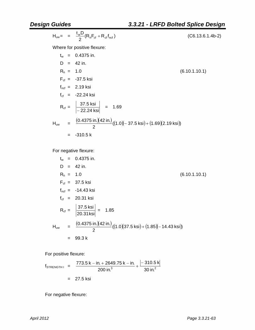
Design Guides 3.3.21 - LRFD Bolted Splice Design
April 2012 Page 3.3.21-63
Huw = = )fRFR(2Dt
ncfcfcfhw + (C6.13.6.1.4b-2)
Where for positive flexure:
tw = 0.4375 in.
D = 42 in.
Rh = 1.0 (6.10.1.10.1)
Fcf = -37.5 ksi
fncf = 2.19 ksi
fcf = -22.24 ksi
Rcf = ksi24.22
ksi5.37−
= 1.69
Huw = ( )( ) ( )( ) ( )( ))ksi19.269.1ksi5.370.1(2
.in42.in4375.0+−
= -310.5 k
For negative flexure:
tw = 0.4375 in.
D = 42 in.
Rh = 1.0 (6.10.1.10.1)
Fcf = 37.5 ksi
fncf = -14.43 ksi
fcf = 20.31 ksi
Rcf = ksi31.20ksi5.37 = 1.85
Huw = ( )( ) ( )( ) ( )( ))ksi43.1485.1ksi5.370.1(2
.in42.in4375.0−+
= 99.3 k
For positive flexure:
fSTRENGTH I = 23 .in30k5.310
.in200.ink75.2649.ink5.773 −
+−+−
= 27.5 ksi
For negative flexure:

Design Guides 3.3.21 - LRFD Bolted Splice Design
Page 3.3.21-64 April 2012
fSTRENGTH I = 23 .in30k3.99
.in200.ink57.4128.ink5.773
+−+−
= 27.8 ksi
27.8 ksi controls.
Compare Strength I Flexural Stress with φfFy (6.13.6.1.4b)
fSTRENGTH I ≤ φfFy
Where:
fSTRENGTH I = 27.8 ksi
φf = 1.0 (6.5.4.2)
Fy = 50 ksi
27.8 ksi < 50 ksi O.K.
Check Web Splice Plate Shear Capacity (6.13.5.3)
Vuw ≤ Rr
Calculate Factored Shear Resistance for Yielding of Gross Web Splice Section
Rr = φv0.58FyAvg (Eq. 6.13.5.3-1)
Where:
Avg = 2(40 in.)(0.375 in.) = 30 in.2
Fy = 50 ksi
φv = 1.0 (6.5.4.2)
Rr = (1.00)(0.58)(50 ksi)(30 in.2)
= 870 k > 221.0 k O.K.

Design Guides 3.3.21 - LRFD Bolted Splice Design
April 2012 Page 3.3.21-65
Calculate Factored Shear Resistance for Fracture of Net Web Splice Section
Rr = φvu0.58RpFuAvn (Eq. 6.13.5.3-2)
Where:
Rp = 1.0
Avn = 2(0.375 in.)(40 in. – (0.9375 in. / hole)(12 holes))
= 21.56 in.2
Fu = 65 ksi
φvu = 0.8 (6.5.4.2)
Rr = (0.8)(0.58)(1.0)(65 ksi)(21.56 in.)
= 650.25 k > 221.0 k O.K.
Check Web Splice Plate Fatigue
Calculate Fatigue Shear Forces,Vrw
From flange design, Fatigue II load case controls.
+rwV
= 3.15 k
−rwV
= -20.1 k
Calculate Fatigue Moment Due to Shear Eccentricity, Mrv (C6.13.6.1.4b)
Mrv = [( +rwV )-( −
rwV )]e, where all variables are as calculated above
= [(3.15 k – (-20.1 k)](3.5 in.)
= 81.4 k-in.
Calculate Fatigue Flexural Moment, Mrw
Mrw = ]ff[12Dt
bwtw
2w − (Modified Eq. C6.13.6.1.4b-1)
For simplicity, use the stresses at mid-thickness of flange instead of the stresses at the
inside faces of the flanges. Again, Fatigue II load case controls.

Design Guides 3.3.21 - LRFD Bolted Splice Design
Page 3.3.21-66 April 2012
For positive flexure:
tw = 0.4375 in.
D = 42 in.
ftw = 0.3 ksi
fbw = -3.02 ksi
+rwM = ( )( ) ( )]ksi02.3ksi3.0[
12.in42.in4375.0 2
−−
= 213.5 k-in.
For negative flexure:
tw = 0.4375 in.
D = 42 in.
ftw = -0.23 ksi
fbw = 2.27 ksi
−rwM = ( )( ) ( )]ksi27.2ksi23.0[
12.in42.in4375.0 2
−−
= -160.8 k-in.
Calculate Fatigue Total Moment Range, Mr-total range
Mr-total range = Mrv + ( +rwM -
−rwM )
= 81.4 k-in. + (213.5 k-in. – (-160.8 k-in.))
= 455.7 k-in.
Calculate Fatigue Design Horizontal Force Resultant
The horizontal force resultant, Hrw, shall be calculated for both positive and negative
flexure.
Hrw = )ff(2Dt
bwtww + (Modified Eq. C6.13.6.1.4b-2)
For positive flexure:
tw = 0.4375 in.
D = 42 in.
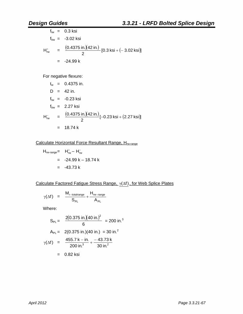
Design Guides 3.3.21 - LRFD Bolted Splice Design
April 2012 Page 3.3.21-67
ftw = 0.3 ksi
fbw = -3.02 ksi
+rwH = ( )( ) ( )]ksi02.3ksi3.0[
2.in42.in4375.0
−+
= -24.99 k
For negative flexure:
tw = 0.4375 in.
D = 42 in.
ftw = -0.23 ksi
fbw = 2.27 ksi
−rwH = ( )( ) ( )]ksi27.2ksi23.0[
2.in42.in4375.0
+−
= 18.74 k
Calculate Horizontal Force Resultant Range, Hrw-range
Hrw-range = +rwH – −
rwH
= -24.99 k – 18.74 k
= -43.73 k
Calculate Factored Fatigue Stress Range, )f(∆γ , for Web Splice Plates
)f(∆γ = PL
rangerw
PL
totalranger
AH
SM −− +
Where:
SPL = ( )( )
6.in40.in375.02 2
= 200 in.3
APL = 2(0.375 in.)(40 in.) = 30 in.2
)f(∆γ = 23 .in30k73.43
.in200.ink7.455 −
+−
= 0.82 ksi

Design Guides 3.3.21 - LRFD Bolted Splice Design
Page 3.3.21-68 April 2012
Check Fatigue Detail Design Criteria (6.6.1.2.2)
From flange design, the allowable stress range for fatigue is 10.06 ksi.
0.82 ksi < 10.06 ksi O.K.
Check Web Splice Bolt Strength
Rr = φsRnR > Pr
Where:
φs = 0.80 (6.5.4.2)
R = 1.0 (since the webs are only 1/16 in. difference in thickness, no filler plates are
used)
Rn = 0.38AbFubNs (kips) (Eq. 6.13.2.7-2)
Where:
Ab = 4
.)in 875.0( 2π = 0.60 in.2
Fub = 120 ksi (6.4.3)
Ns = 2
Rn = 0.38(0.60 in.2)(120 ksi)(2)
= 54.72 k
Calculate the Polar Moment of Inertia
∑ 2y = 2(2)(17.875 in.)2+2(2)(14.625 in.)2+2(2)(11.375 in.)2+2(2)(8.125 in.)2
+2(2)(4.875 in.)2+2(2)(1.625 in.)2
= 3020.88 in.2
∑ 2x = 12(2)(1.5 in.)2 = 54.00 in.2
Ip = 3020.88 in.2+54.00 in.2 = 3074.88 in.2
Calculate Strength I Resultant Shear for Bolts, Pr
From plate check, positive moments control the Strength I design.
Pr = ( ) ( )2MHH
2MVS PPPP +++

Design Guides 3.3.21 - LRFD Bolted Splice Design
April 2012 Page 3.3.21-69
Where:
PS = b
uw
NV
= 24
k 21.02 = 9.21 kips per bolt
PH = b
uw
NH
= 24
k 310.5− = 12.94 kips per bolt
PMH = ( )p
uwuv
IyMM + = ( )( )
2.in88.3074.in875.17.ink75.2649.ink5.773 −+− = 19.90 k
PMV = ( )p
uwuv
IxMM + = ( )( )
2.in88.3074.in5.1.ink75.2649.ink5.773 −+− = 1.67 k
Pr = ( ) ( )22 k 90.19k 2.941k 67.1k .219 +++ = 34.60 k
34.60 k < 54.72 k O.K.
Check Web Splice Bolt Slip
Calculate Service II Shears for Web Splice Plates
Vow = 135.42 k (see above)
Calculate Service II Flexural Moment (C6.13.6.1.4b)
Mov = Vowe = (135.42 k)(3.5 in.) = 473.97 k-in.
Mow = ]ff[12Dt
bwtw
2w −
For simplicity, use the stresses at mid-thickness of flange instead of the stresses at the
inside faces of the flanges.
For positive flexure:
tw = 0.4375 in.
D = 42 in.
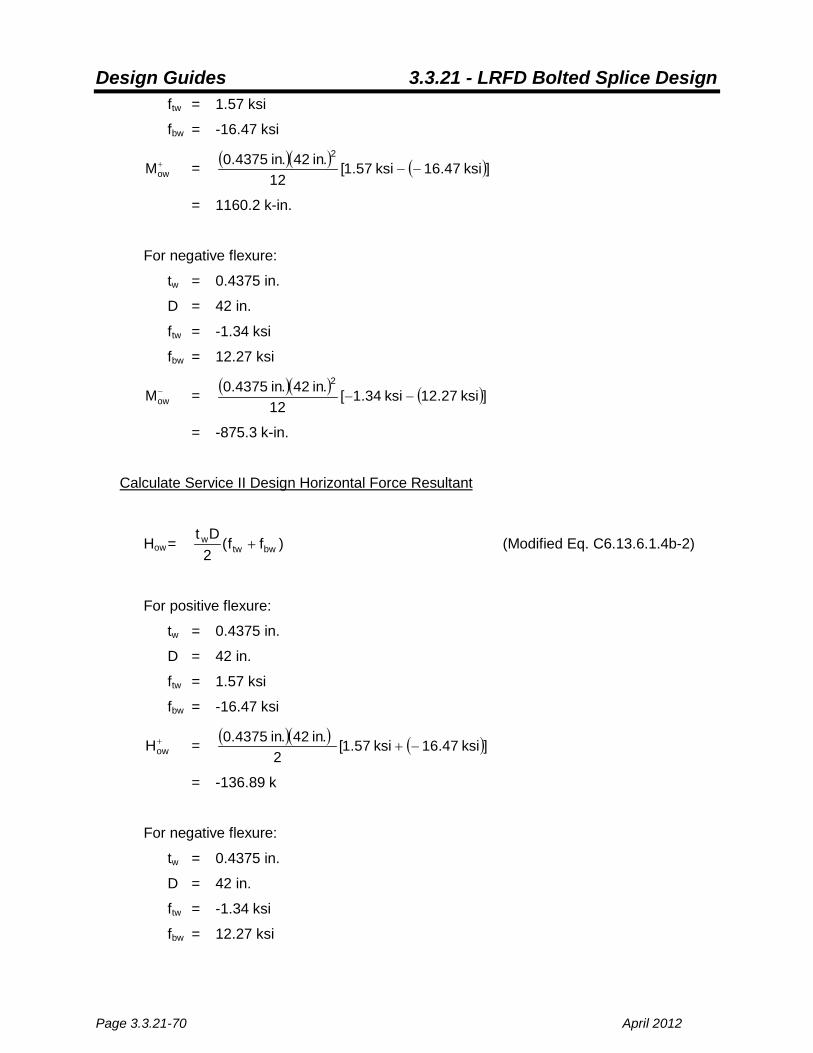
Design Guides 3.3.21 - LRFD Bolted Splice Design
Page 3.3.21-70 April 2012
ftw = 1.57 ksi
fbw = -16.47 ksi
+owM = ( )( ) ( )]ksi47.16ksi57.1[
12.in42.in4375.0 2
−−
= 1160.2 k-in.
For negative flexure:
tw = 0.4375 in.
D = 42 in.
ftw = -1.34 ksi
fbw = 12.27 ksi
−owM = ( )( ) ( )]ksi27.12ksi34.1[
12.in42.in4375.0 2
−−
= -875.3 k-in.
Calculate Service II Design Horizontal Force Resultant
How = )ff(2Dt
bwtww + (Modified Eq. C6.13.6.1.4b-2)
For positive flexure:
tw = 0.4375 in.
D = 42 in.
ftw = 1.57 ksi
fbw = -16.47 ksi
+owH = ( )( ) ( )]ksi47.16ksi57.1[
2.in42.in4375.0
−+
= -136.89 k
For negative flexure:
tw = 0.4375 in.
D = 42 in.
ftw = -1.34 ksi
fbw = 12.27 ksi

Design Guides 3.3.21 - LRFD Bolted Splice Design
April 2012 Page 3.3.21-71
−owH = ( )( ) ( )]ksi27.12ksi34.1[
2.in42.in4375.0
+−
= 100.42 k
Calculate Service II Resultant Shear for Bolts
Por = ( ) ( )2oMHoH
2oMVos PPPP +++
For positive flexure:
PoS = b
ow
NV
= 24
k 35.421 = 5.64 kips per bolt
PoH = b
ow
NH
= 24
k 89.361− = 5.7 kips per bolt
PMH = ( )p
owov
IyMM + =
( )( )2.in88.3074
.in875.17.ink2.1160.ink97.473 −+− = 9.50 k
PMV = ( )p
owov
IxMM + =
( )( )2.in88.3074
.in5.1.ink2.1160.ink97.473 −+− = 0.80 k
Pr = ( ) ( )22 k 50.9k .705k 80.0k .645 +++ = 16.51 k
For negative flexure:
PoS = b
ow
NV
= 24
k 35.421 = 5.64 kips per bolt
PoH = b
ow
NH
= 24
k 00.421 = 4.18 kips per bolt
PMH = ( )p
owov
IyMM + =
( )( )( )2.in88.3074
.in875.17.ink3.875.ink97.473 −−+− = -2.33 k
PMV = ( )p
owov
IxMM + = ( )( )( )
2.in88.3074.in5.1.ink3.875.ink97.473 −−+− = -0.20 k
Pr = ( )( ) ( )( )22 k 33.2k .184k 20.0k .645 −++−+ = 6.13 k
Calculate Factored Slip Resistance for Bolts, Rr (6.13.2.2)
Rn = φRn (Eq. 6.13.2.2-2)
Where:

Design Guides 3.3.21 - LRFD Bolted Splice Design
Page 3.3.21-72 April 2012
φ = 1.00 (6.5.4.2)
Rn = KhKsNsPt (kips)
Kh = 1.00 (Table 6.13.2.8-2)
Ks = 0.33 (Table 6.13.2.8-3)
Ns = 2
Pt = 39 k (Table 6.13.2.8-1)
Rn = (1.00)(1.00)(0.33)(2)(39 k)
= 25.74 k > 16.51 k O.K.
Check Web Splice Plate Block Shear
Vuw ≤ Rr
Where:
Rr = φbs(0.58FuAvn) (Modified Eq. 6.13.4-2)
Where:
Avn = (40 in. – 12 holes * 0.9375 in./hole)(0.375 in.)
= 10.78 in.2
Fu = 65 ksi
φbs = 0.80 (6.5.4.2)
Rr = φbs(0.58FuAvn)
= 0.8(0.58)(65 ksi)(10.78 in.2)
= 325.1 k > 221.0 k O.K.
Check Extreme Bolt Bearing
The extreme corner of the splice plate has a 2.125 in. distance from the center of the bolt to
the edge of the plate, and can utilize the thickness of both splice plates in determining the
bearing capacity. The top or bottom bolt adjacent to the end of beam only has a 1.875 in.
distance from the center of the bolt to the end of the beam segment, and can only use the
smaller web thickness in determining the capacity. The top or bottom bolt adjacent to the
end of the beam controls by inspection.

Design Guides 3.3.21 - LRFD Bolted Splice Design
April 2012 Page 3.3.21-73
Pr ≤ Rr
Where:
Pr = 34.6 k (See Strength I design calculations)
Rr = φbbRn
Where:
φbb = 0.80 (6.5.4.2)
If xclear ≥ 2.0d and xend ≥ 2.0d:
Rn = 2.4dtFu (Eq. 6.13.2.9-1)
If xclear < 2.0d or xend < 2.0d:
Rn = 1.2LctFu (Eq. 6.13.2.9-2)
Where:
xclear = 2.31 in. or 2.06 in.
xend = 1.875 in. – 0.5(0.9375 in.) = 1.41 in.
d = 0.875 in.
xclear ≥ 2.0d but xend < 2.0d, ∴ Rn = 1.2LctFu
Where:
t = 0.4375 in. web thickness
Fu = 65 ksi (Table 6.4.1-1)
Lc = 1.41 in.
Rn = 1.2(1.41 in.)(0.4375 in.)(65 ksi)
= 48.11 k
Rr = (0.80)(48.11 k) = 38.5 k > 34.6 k O.K.
Check Web Splice Bolt Spacing
Using Bridge Manual Figures 3.3.21-1 and 3.3.21-3, spacing O.K.


