
1
Design and implementation of broom sticks
machine
By:
Salah-Adeen Jamal Zamaereh
Omar Waleed Abu Danhash
Supervisor:
Eng. Jalal Alsalaymeh
Submitted to the College of Engineering
in partial fulfillment of the requirements for the
Bachelor degree in Automotive Engineering
Palestine Polytechnic University
2018-2019
2

3
Dedication (Arabic)
إ اؼ الأي .. إ لائذ ز الأت لذتا .. سسا محمد صاث الله سلا ػ١
س بى افتخاس .. أسخ إإ و الله با١بت الاس .. إ ػ اؼطاء د اتظاس .. إ أز
الله أ ٠ذ ف ػشن تش ثاسا لذ زا لطافا بؼذ طي اتظاس ستبم واته د أتذ با ا١ ف ا
. اغذ إ الأبذ
(اذ اؼز٠ز)
إ لاو ف اس١اة .. إ ؼ اسب اسا اتفا .. إ بست اس١اة سش ات١ز إ وا دػائا سش داز زاا بس خشاز إ أغ الأزبا .
(أ اغا١ت(
بساػذت تستشق ت١ش ا اطش٠ك .. إ اؼ اؼشفت .. إ ػبشا ػ أ٠ذ٠ إ اشع ات
إ ػا زشفا رب واث دسس... بش الأاإ سػا٠ت
)أساتزتا الأفاض(
.إ الأسد امابؼت خف امضبا .. إ ضسا بسش٠ت أخ زش٠ت غ١ش
)الأسش الأبطاي(
.ف سب١ تسش٠ش زا اط إ ضسا بذائإ أوش ا ىات ..
)اشذاء الأبشاس(
سشا س٠ا شك اطش٠ك ؼا س اداذ الإبذاع .. إ و شسا ب ػ دس اؼ اثابشة. إ
)ازلاء از١لاث(
إ تسا إ سفماء اذس .. سخاي االف .. أصسا ا اطزاث اؼا١ت .. ػا اثابشة ..
بالإخاء .. ت١زا باصذق اؼطاء.
)أصذلائ الأزبا (
.. إ اط اغا .. إ الأسض ات إزتضتا
اشذاء دؼت د إ وش اؼب غص از٠ت..…إ اسبت ازب١ت ف بلاد ب١اساث ابشتماي
..ػتشزإ سغ١ف اطاب س٠ر ا.. فايالأط
ا ته ات صؼت و أو ا
)فسط١ اسب١بت(

4
Acknowledgment
We would like to express our gratitude for everyone who helps us during the
graduation project, starting with endless thanks for our supervisor Eng. Jalal
Alsalaymeh who didn’t keep any effort in encouraging us to do a great job, providing
us with valuable information and advices to be better each time. Thanks for the
continuous support and kind communication which great effect regarding to feel
interesting about what we are working on.
Finally, Thanks are extended to the "Automotive and Mechanical society" for the
beneficial lectures provided.

5
Abstract (in English)
Broom sticks are imported from abroad as there is no local manufacturer in Palestine.
Import is expensive and consumption is high. However, there are technical problems
such as curving the stick and the losing of threads sticks.
This project aims to solve this problem by designing and implementing the machine
to make the broom sticks in a mechanical way. The machine takes the wood with a
square cross section and does a cylindrical broom sticks by using the turning. Such
machine makes the thread of these sticks then ready to be used. In addition, this
machine will reduce the imports and produce a high-quality of local product.

6
Abstract (in Arabic)
٠ت است١شاد ػص اىاس ف فسط١ اخاسج لا ٠خذ تص١غ س ، ز١ث أ الإست١شاد ىف
ىاا . الإستلان ػا ٠خذ ف١ا شاو ف١ت وتم٠ست اؼصا خشج أسا اؼص
٠ذف زا اششع ا ز ز اشىت خلاي تص١ تف١ز اوت صاػت ػص اىاس بطش٠مت
١ىا١ى١ت ز١ث تم ااوت بأخز اخشب ر مطغ ػشض شبغ تؼ ػص ىاس اسطا١ت اشى
تم ااوت أ٠ضا بؼ١ت تس١ ز اؼص بس١ث تى خازة لإستؼاي . باسطت اخشاطت
م١ الإست١شاد إتاج تح س ػا اددة .تااوت طبت
7
List of contents
Acknowledgment ........................................................................................................ 4
Abstract (in English) ................................................................................................... 5
Abstract (in Arabic) .................................................................................................... 6
List of contents ............................................................................................................ 7
List of Figures ........................................................................................................... 10
List of Tables ............................................................................................................ 12
Chapter 1: Introduction ............................................................................................ 13
1.1 Introduction ..................................................................................................... 13
1.2 Problem definition ............................................................................................ 14
1.3 Motivation ....................................................................................................... 14
1.4 Expected output ............................................................................................... 14
1.5 Methodology .................................................................................................... 14
1.6 Budget ............................................................................................................. 15
1.7 Time schedule .................................................................................................. 16
1.8 Machine Specifications ..................................................................................... 18
1.9 Broom stick specifications ................................................................................ 18
1.10 Literature Review ........................................................................................... 19
Chapter 2: Wood Turning ......................................................................................... 23
2.1 Introduction ..................................................................................................... 23
2.2: The Lathe ....................................................................................................... 24
2.2.1: Speed of the lathe ...................................................................................... 24
2.2.2 : Rules for finding the speeds and sizes of pulleys ........................................ 26
2.2.3 Grinding and whetting turning tools ........................................................... 26
2.3 Threading process [11] ....................................................................................... 28
2.3.1 Thread calculations .................................................................................... 28
2.3.2 Screw thread cutting [12] .............................................................................. 29
2.3.3 Screw thread terminology........................................................................... 29
2.3.4 Methods turning lathe screw ...................................................................... 31
Chapter 3: Components of machine ........................................................................... 33
3.1 Introduction ..................................................................................................... 33
3.2 Machine Parts .................................................................................................. 33
3.2.1 Machine Image .......................................................................................... 33
3.2.2 Cutting Head ............................................................................................. 35
3.2.3 Knives ....................................................................................................... 35

8
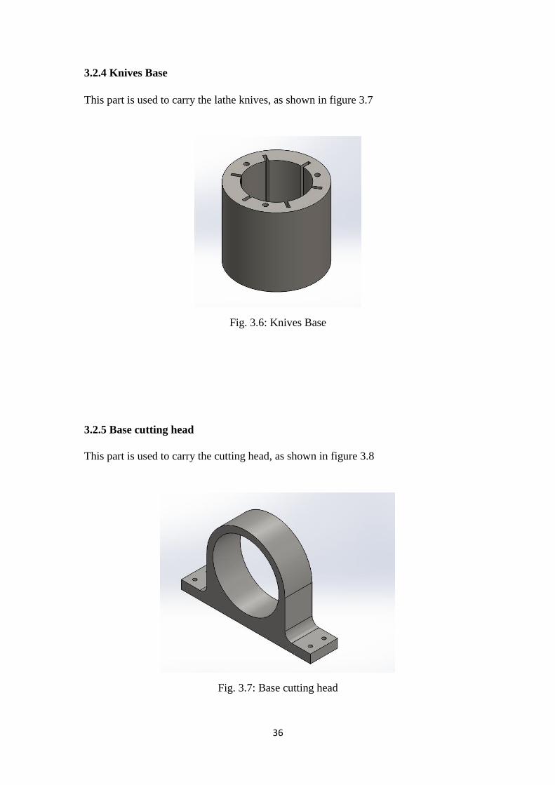
3.2.4 Knives Base ............................................................................................... 36
3.2.5 Base cutting head ....................................................................................... 36
3.2.6 Types of Bering .......................................................................................... 37
3.2.7 Motors ....................................................................................................... 38
3.2.8 Frame ........................................................................................................ 38
3.2.9 Belt ............................................................................................................ 39
3.3 Threading parts ............................................................................................... 39
Chapter 4: Machine design [14] ................................................................................... 40
4.1 Introduction ..................................................................................................... 40
4.2 Mechanical design ............................................................................................ 40
4.2.A Calculate the cutting or turning part of the wood pole ................................ 40
4.2.B Find the relationship between the speed of the knife rotation and the speed of
the wood pole ..................................................................................................... 44
4.2.C Calculate the forces located on the lathe knife ............................................ 45
4.2.D Calculate knife properties .......................................................................... 47
The result: ......................................................................................................... 50
4.2.E Calculate the pressure on the wood pole to push the pole toward the knives . 50
4.2.F Calculate the motor needed to turn the turning pole .................................... 52
4.2.G Calculate motor power to push wood ......................................................... 54
4.2.H Buckling ................................................................................................... 56
4.2.I Torsional shear stress ................................................................................. 56
4.2.J Belt drive selection "V-Belt" ....................................................................... 58
Summary of belt design: ..................................................................................... 61
4.2.k To calculate the deflection: ......................................................................... 62
4.2.L To calculate Buckling ............................................................................... 62
4.2.M To calculate maximum normal stress: ....................................................... 63
4.2.N To calculate the deflection: ........................................................................ 63
4.2.O To calculate the deflection: ........................................................................ 64
4.2.P To calculate the shear: ............................................................................... 65
4.2.Q To calculate the energy: ............................................................................. 66
4.2.R To calculate the shear in shaft: ................................................................... 66
4.3 Electrical design ............................................................................................... 68
4.3.A Motors ...................................................................................................... 68
4.3.B Switches & Controlled switches.................................................................... 69
4.3.C Variable Frequency Drive (VFD) or "inverter” .......................................... 70
4.3.D Electrical protection .................................................................................. 71

9
4.3.E Lamp ........................................................................................................ 73
4.3.F Wiring diagram (power and control circuit) ............................................... 74
Chapter 5: Simulation of frame and shaft .................................................................. 76
5.1 Simulation of frame .......................................................................................... 76
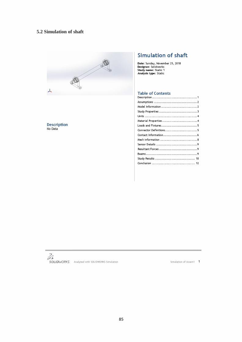
5.2 Simulation of shaft ........................................................................................... 85
Chapter 6: Conclusions and recommendations ........................................................... 97
6.1 Conclusions ...................................................................................................... 97
6.2 Recommendations ............................................................................................ 97
Appendix .................................................................................................................. 98
References .............................................................................................................. 103

11
List of Figures
Fig. 1.1: Broom Stick……………………………………………………………...…13
Fig. 1.2: Broom having interlocking components………………………………........19
Fig. 1.3: Handle socket adapter…………………………………………………...….20
Fig. 1.4: Modular handle particularly for brooms and like………………………..…21
Fig. 1.5: Modular handle particularly for brooms and like………………...………...21
Fig. 2.1: Lathe machine………………………………………………………...….…23
Fig. 2.2: Operations related to turning………………………………………….....…24
Fig. 2.3: Wood turning lathe……………………………………………………..…..25
Fig. 2.4: Wood turning lathe………………………………………………………....25
Fig. 2.5: Lathe Tools……………………………………………………………........27
Fig. 2.6: Lathe machine cutting tools………………………………………...……....27
Fig. 2.7: Thread and feed chart………………………………………………………28
Fig. 2.8: Screw thread terminology………………………………………..…………29
Fig. 2.9: Screw thread types……………………………………………………..…...30
Fig. 2.10: Methods turning lathe screw………………………………………………31
Fig. 2.11: Thread cutting operation on lathe machine………………………...……...32
Fig. 3.1: Machine Image………………………………………………...…………...34
Fig. 3.2: Frontal machine image…………………………………………...…………35
Fig. 3.3: Side machine image………………………………………………………...35
Fig. 3.4: Cutting Head……………………………………………………………......36
Fig. 3.5: Knives…………………………………………………………...………….36
Fig. 3.6: Knives Base………………………………………………………………...37
Fig. 3.7: Base cutting head………………………………………...…………………37
Fig. 3.8: Feed Bearing………………………………………………………...…….38
Fig. 3.9: Output Bearing……………………………………………………….........38
Fig. 3.10: Motors……………………………………………………………...…...…39
Fig. 3.11: Frame……………………………………………………………………...39
Fig. 3.12: Belt…………………………………………………………………….......40
11
Fig. 3.13: Special thread head………………………………………………………..40
Fig. 4.1: Knife……………………………………………………………………..…42
Fig. 4.2: Wood pole and abraded part…………………………………………...…...43
Fig. 4.3: Wood cutting section………………………………………………….…....43
Fig. 4.4: Abraded part and knife angle………………………………………….....…44
Fig. 4.5: Cutting volume…………………………………………………………..…45
Fig. 4.6: Wood pole……………………………………………………………...…...46
Fig. 4.7: Force acting on the knife…………………………………………………...48
Fig. 4.8: Knife and stand out………………………………………………………....49
Fig. 4.9: Knife properties………………………………………………………..…...50
Fig. 4.10: Force acting on the knife…………………………………………….....…51
Fig. 4.11: Deflection on the knife……………………………………………………51
Fig. 4.12: Wood pole torque…………………………………………………………54
Fig. 4.13: Diameter of pulley cutting head and motor pulley………………………..55
Fig. 4.14: motor power to push wood………………………………………………..56
Fig. 4.15: Buckling………………………………………………………...…………58
Fig. 4.16: Total machine dimensions………………………………………………...59
Fig. 4.17: Calculate the deflection…………………………………………………....64
Fig. 4.18: Calculate the deflection-uniform load……………………………….……66
Fig. 4.19: Push-button switches……………………………………………………...71
Fig. 4.20: Contactors……………………………………………………………........72
Fig. 4.21: Inverter………………………………………………………………….…72
Fig. 4.22: Circuit breaker…………………………………………………………….73
Fig. 4.23: Circuit breaker…………………………………………………………….73
Fig. 4.24: Overload…………………………………………………………………...74
Fig. 4.25: Fuses………………………………………………………………………74
Fig. 4.26: Emergency stop…………………………………………………………....75
Fig. 4.27: Lamp……………………………………………………………………....75

12
List of Tables
Table 1: Budget………………………………………………………….………...…15
Table 2: Time schedule for introduction of the project……………………………....16
Table 3: Time schedule for the project…………………………………………….....17
Table 4: Rotating motor specifications………………………………………………70
Table 5: Push motor specifications…………………………………..………………70
Table 6: Threading motor specifications……………………………………………..71
13
Chapter 1: Introduction
This chapter deals with a general introduction of the project and then talks about the
problem definition, why this topic is chosen, how the project is implemented, and the
expected costs of this project, also we will talk about the outputs of this project and
the time distribution of each section..
1.1 Introduction
The broom sticks are a high consumption product in Palestinian society, it is imported
from abroad because there is no local industry supplying the local market.
So, it was important to have an industry that matched the imported one, and competed
in the price, quality and its life span.
There are several common uses in the Palestinian community for broom sticks such
as: brooms, paint brushes, advertising banners, …, etc.
This project is one of the most important and required projects in the local market,
and it is expected to have high production and great profit due to the uniqueness of it
in the market and the urgent need for it.
What Is a Broom Stick
A broom is a cleaning tool consisting of usually stiff fibers (often made of materials
such as plastic, hair, or corn husks) attached to, and roughly parallel to, a cylindrical
handle, the broomstick. It is thus a variety of brush with a long handle. It is commonly
used in combination with a dustpan.
A distinction is made between a "hard broom" and a "soft broom". Soft brooms are
for sweeping walls of cobwebs and spiders.
Hard brooms are for sweeping dirt off
sidewalks.
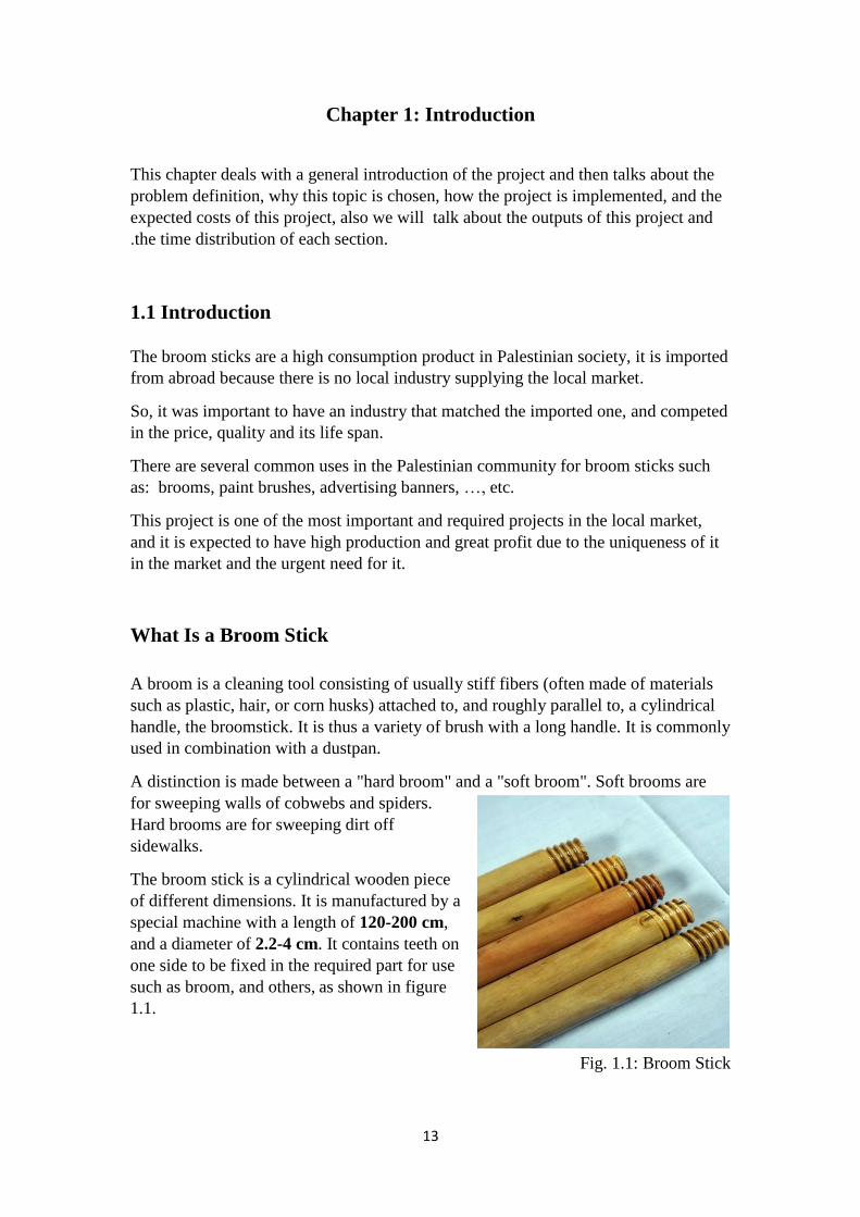
The broom stick is a cylindrical wooden piece
of different dimensions. It is manufactured by a
special machine with a length of 120-200 cm,
and a diameter of 2.2-4 cm. It contains teeth on
one side to be fixed in the required part for use
such as broom, and others, as shown in figure
1.1.
Fig. 1.1: Broom Stick
14
1.2 Problem definition
There are many types of problems in this scope broom sticks:
Economic problem: high consumption and high importation. .1
2.Technical problem:
Curvature occurs in the stick. *
* Losing of threads sticks.
1.3 Motivation
The importance of our project is to solve the existing problem by reducing imports
and producing a local product with high quality, lower price and longer life.
How to solve this problem
1. Economically: issue manufacturing a local high quality, long life and a lower price
machine, which reduces the external import.
2. Technically: Using high quality machine and raise the quality of the product and
avoid defect.
1.4 Expected output
The design and implementation of a machine to manufacture broom sticks that ready
for use.
1.5 Methodology
In this project we we'll design and implement a machine to manufacture the broom
sticks in a mechanical way containing a rotating rotary head that turns the cross
section into a cylindrical circular section by turning.
The thread of one end of the stick are then made to be ready for use, taking into
account occupational safety requirements.

15
1.6 Budget
The Table below shows the budget of the project and its distribution. The budget of
the project is estimated to be around 8500 NIS, In Table 1 is listed the needed
components for the project, the price of each component's single unit, the number of
units needed of each component, and the total price for each component.
Table 1: Budget
Price (NIS) Components
3000 Motor's and gears (3)
3000 Raw materials and lathing
50 Belt (2)
80 Bearing (2)
200 Pulleys (4)
1400 Inverter
80 Contactors (2)
35 Emergency
280 Over load (2)
150 Screws, bolts and nuts
200 Other components
8475 NIS Total cost

16
1.7 Time schedule
Table 2: Time schedule for introduction of the project
First semester
Task\Week 1 2 3 4 5 6 7 8 9 10 11 12 13 14 15 16
Identifying
the project
idea
Writing
project
name and
abstract and
proposal
Literature
review
Drawing the
machine
and parts
Writing the
project
Reference
and make
presentation
and
finishing

17
Table 3: Time schedule for the project
Second semester
Task\Week 1 2 3 4 5 6 7 8 9 10 11 12 13 14 15 16
Mechanical
and
electrical
design
calculations
Buying the
machine
parts
Building the
machine
body and
turning
parts
Mechanical
and
electrical
parts
assembly
Writing the
project and
make
presentation
and
finishing

18
1.8 Machine Specifications
1- The production rate of the machine is 250 stick per hour
2- The machine is 85 cm in height, 40 cm in width, and 75 cm in length
3- The machine is 200 kg in weight
4- The body of the machine is made from steel, but the cutting head is made from
very hard steel (S-52)
5- The rotating motor works on 1-phase, 3 HP, 380/220v, 50Hz
6- The push motor works on 1-phase, 0.5 HP, 380/220v, 50Hz
1.9 Broom stick specifications
1- The broom stick is 120 cm in length, and 3 cm in diameter
2- The broom stick is 0.5 kg in weight, and 0.7 g/cm³ in density
3- The broom stick is made of pine wood " Hardwood"
4- The broom stick is used extensively for example: in brooms, Wipers, advertising
and painting and other.
19
1.10 Literature Review
This subject will talk about previous studies which presents the methods used by
researchers in this topic, which can benefit from their experiences and research done
to complete our project.
Wooden Broom Assembly Adapter Means Therefore, Thomas J.
Carey, Aug. 12, 1991
The main idea of this paper A broom assembly of a basically wooden push broom
comprises a wooden head portion including top and bottom surfaces, leading and
trailing edge portions and remote lateral extremities, considering the direction of its
movement in use. This head has a laterally centered through bore opening at one end
from the tope there of adjacent its trailing edge and at its opposite end from the
bottom thereof, adjacent its leading edge. A counterbore of the upper end of this
through bore produces an outwardly and rearwardly facing annular shoulder in
its bounding wall surfaces. Securely wedged within this through bore, towards its
bottom, is the short tubular body portion of a rigid plastic adapter means, an external
flange at the base end of which overlies the bottom of the head and an external lip at
the upper end of which clamps over the aforementioned shoulder in the wall bounding
the upper end of the through bore. The adapter means is thereby clamped to and
contains within the axial limits thereof an integral part of the head. In the lodging
thereof within the through bore, differentially formed portions of the external surface
of the tubular body portion of the adapter means differentially wedge in its bounding
wall surface, effectively precluding its relative rotative displacement. A small portion
of the inner surface of the adapter means has a short truncated thread the form of
which enables an easy and most secure connection thereto of a complementarily
formed portion of an applied handle.[1]
Design and Prototyping of a Low-Cost Manually Operated Bamboo-
Cored Incense-Stick Making Machine, G. Keshav & M. Damodaran,
India, Dec 18-20 2013
The main idea of this paper the design and prototyping of a low cost hand operated
incense-stick making machine to alleviate the labor intensive work associated with the
production of bamboo-cored incense sticks is outlined in this paper. The machine is
based on the mechanism of extruding the incense stick paste over the bamboo stick.
The main components of this machine include a hand-crank, a compound gear-train
system, rack and pinion system and an extruder. As the paste used is of a semi-solid
nature and a high force was needed for extrusion, a confined compression test using
Universal Testing Machine was carried out to obtain rough estimates of the force
required for the extrusion. During this experiment a known force was applied, varied
and exerted on the rack until the paste was extruded out of the die. Using this force
21
estimate, a suitable two-stage compound gear-train system with mechanical advantage
of 9:1 and a hand-crank was designed. The lever and gear-train system was designed
ergonomically so that the applied force results in a minimal arm-muscle fatigue for
the operator.[2]
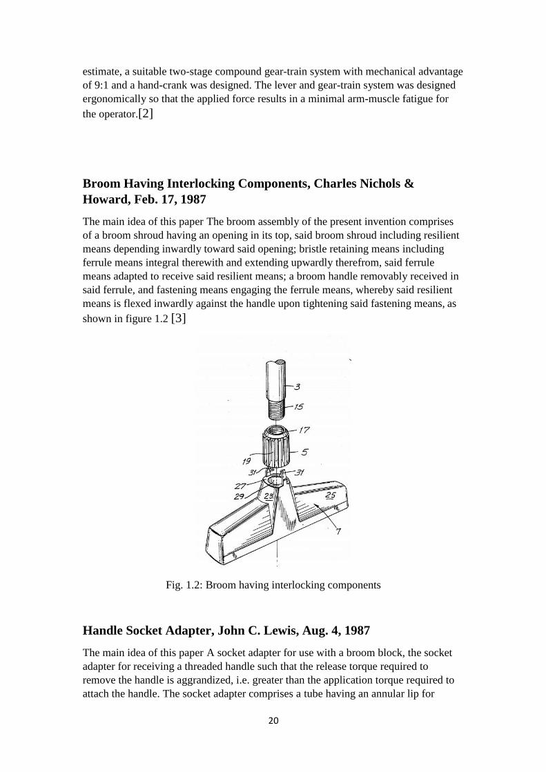
Broom Having Interlocking Components, Charles Nichols &
Howard, Feb. 17, 1987
The main idea of this paper The broom assembly of the present invention comprises
of a broom shroud having an opening in its top, said broom shroud including resilient
means depending inwardly toward said opening; bristle retaining means including
ferrule means integral therewith and extending upwardly therefrom, said ferrule
means adapted to receive said resilient means; a broom handle removably received in
said ferrule, and fastening means engaging the ferrule means, whereby said resilient
means is flexed inwardly against the handle upon tightening said fastening means, as
shown in figure 1.2 [3]
Fig. 1.2: Broom having interlocking components
Handle Socket Adapter, John C. Lewis, Aug. 4, 1987
The main idea of this paper A socket adapter for use with a broom block, the socket
adapter for receiving a threaded handle such that the release torque required to
remove the handle is aggrandized, i.e. greater than the application torque required to
attach the handle. The socket adapter comprises a tube having an annular lip for
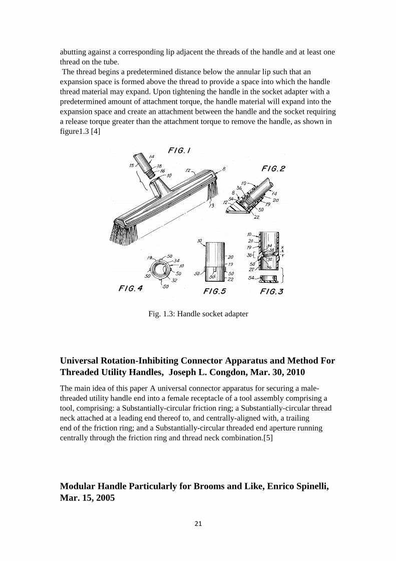
21
abutting against a corresponding lip adjacent the threads of the handle and at least one
thread on the tube.
The thread begins a predetermined distance below the annular lip such that an
expansion space is formed above the thread to provide a space into which the handle
thread material may expand. Upon tightening the handle in the socket adapter with a
predetermined amount of attachment torque, the handle material will expand into the
expansion space and create an attachment between the handle and the socket requiring
a release torque greater than the attachment torque to remove the handle, as shown in
figure1.3 [4]
Fig. 1.3: Handle socket adapter
Universal Rotation-Inhibiting Connector Apparatus and Method For
Threaded Utility Handles, Joseph L. Congdon, Mar. 30, 2010
The main idea of this paper A universal connector apparatus for securing a male-
threaded utility handle end into a female receptacle of a tool assembly comprising a
tool, comprising: a Substantially-circular friction ring; a Substantially-circular thread
neck attached at a leading end thereof to, and centrally-aligned with, a trailing
end of the friction ring; and a Substantially-circular threaded end aperture running
centrally through the friction ring and thread neck combination.[5]
Modular Handle Particularly for Brooms and Like, Enrico Spinelli,
Mar. 15, 2005
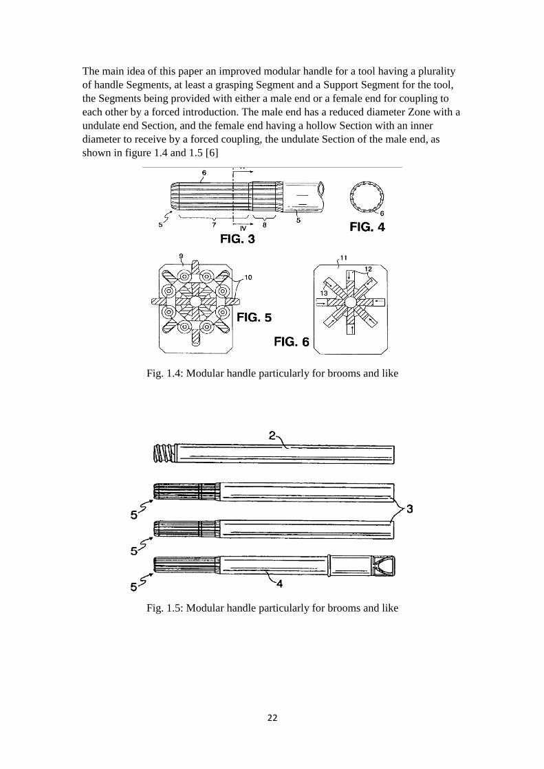
22
The main idea of this paper an improved modular handle for a tool having a plurality
of handle Segments, at least a grasping Segment and a Support Segment for the tool,
the Segments being provided with either a male end or a female end for coupling to
each other by a forced introduction. The male end has a reduced diameter Zone with a
undulate end Section, and the female end having a hollow Section with an inner
diameter to receive by a forced coupling, the undulate Section of the male end, as
shown in figure 1.4 and 1.5 [6]
Fig. 1.4: Modular handle particularly for brooms and like
Fig. 1.5: Modular handle particularly for brooms and like
23
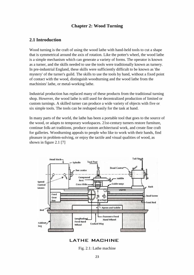
Chapter 2: Wood Turning
2.1 Introduction
Wood turning is the craft of using the wood lathe with hand-held tools to cut a shape
that is symmetrical around the axis of rotation. Like the potter's wheel, the wood lathe
is a simple mechanism which can generate a variety of forms. The operator is known
as a turner, and the skills needed to use the tools were traditionally known as turnery.
In pre-industrial England, these skills were sufficiently difficult to be known as 'the
mystery' of the turner's guild. The skills to use the tools by hand, without a fixed point
of contact with the wood, distinguish woodturning and the wood lathe from the
machinists' lathe, or metal-working lathe.
Industrial production has replaced many of these products from the traditional turning
shop. However, the wood lathe is still used for decentralized production of limited or
custom turnings. A skilled turner can produce a wide variety of objects with five or
six simple tools. The tools can be reshaped easily for the task at hand.
In many parts of the world, the lathe has been a portable tool that goes to the source of
the wood, or adapts to temporary workspaces. 21st-century turners restore furniture,
continue folk-art traditions, produce custom architectural work, and create fine craft
for galleries. Woodturning appeals to people who like to work with their hands, find
pleasure in problem-solving, or enjoy the tactile and visual qualities of wood, as
shown in figure 2.1 [7]
Fig. 2.1: Lathe machine
24
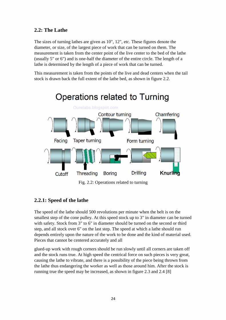
2.2: The Lathe
The sizes of turning lathes are given as 10", 12", etc. These figures denote the
diameter, or size, of the largest piece of work that can be turned on them. The
measurement is taken from the center point of the live center to the bed of the lathe
(usually 5" or 6") and is one-half the diameter of the entire circle. The length of a
lathe is determined by the length of a piece of work that can be turned.
This measurement is taken from the points of the live and dead centers when the tail
stock is drawn back the full extent of the lathe bed, as shown in figure 2.2.
Fig. 2.2: Operations related to turning
2.2.1: Speed of the lathe
The speed of the lathe should 500 revolutions per minute when the belt is on the
smallest step of the cone pulley. At this speed stock up to 3" in diameter can be turned
with safety. Stock from 3" to 6" in diameter should be turned on the second or third
step, and all stock over 6" on the last step. The speed at which a lathe should run
depends entirely upon the nature of the work to be done and the kind of material used.
Pieces that cannot be centered accurately and all
glued-up work with rough corners should be run slowly until all corners are taken off
and the stock runs true. At high speed the centrical force on such pieces is very great,
causing the lathe to vibrate, and there is a possibility of the piece being thrown from
the lathe thus endangering the worker as well as those around him. After the stock is
running true the speed may be increased, as shown in figure 2.3 and 2.4 [8]

25
Fig. 2.3: Wood turning lathe
Fig. 2.4: Wood turning lathe

26
2.2.2 : Rules for finding the speeds and sizes of pulleys
1. To find the diameter of the driving pulley:
Multiply the diameter of the driven by the number of revolutions it should make and
divide the product by the number of revolutions of the driver. (20 x 300 = 6000; 6000
÷ 1500 = 4"-- diameter of motor pulley.)
2. To find the diameter of the driven pulley:
Multiply the diameter of the driver by its number of revolutions and divide the
product by the number of revolutions of the driven. (4 x 1500 = 6000; 6000 ÷ 300 =
20"--diameter of the driven pulley.)
3. To find the number of revolutions of the driven pulley:
Multiply the diameter of the driver by its number of revolutions and divide by the
diameter of the driven. (4 x 1500 = 6000; 6000 ÷ 20 = 300--revolutions of driven
pulley.)
2.2.3 Grinding and whetting turning tools
The skew chisel is sharpened equally on both sides on this tool the cutting edge should form
an angle of about 20° with one of the edges. The skew is used in cutting both to the right and
to the left, and therefore, must be beveled on both sides. The length of the bevel should equal
about twice the thickness of the chisel at the point where it is sharpened. In grinding the
bevel, the chisel must be held so that the cutting edge will be parallel to the axis of the emery
wheel. The wheel should be about 6" in diameter as this will leave the bevel slightly hollow
ground. Cool the chisel in water
occasionally when using a dry emery. Otherwise the wheel will burn the chisel, taking out the
temper; the metal will be soft and the edge will not stand up. Care should be exercised that the
same bevel is kept so that it will be uniformly hollow ground. The rough edge left by the
emery wheel should be whetted off with a slip stone by holding the chisel on the flat side of
the stone so that the toe and heel of the bevel are equally in contact with it. Rub first on one
side and then on the other.
The wire edge is thus worn off quickly as there is no metal to be worn away in the middle of
the bevels. The chisel is sharp when the edge, which may be tested by drawing it over the
thumb nail, is smooth and will take hold evenly along its entire length. If any wire edge
remains it should be whetted again, as shown in figure 2.5 and 2.6 [9]
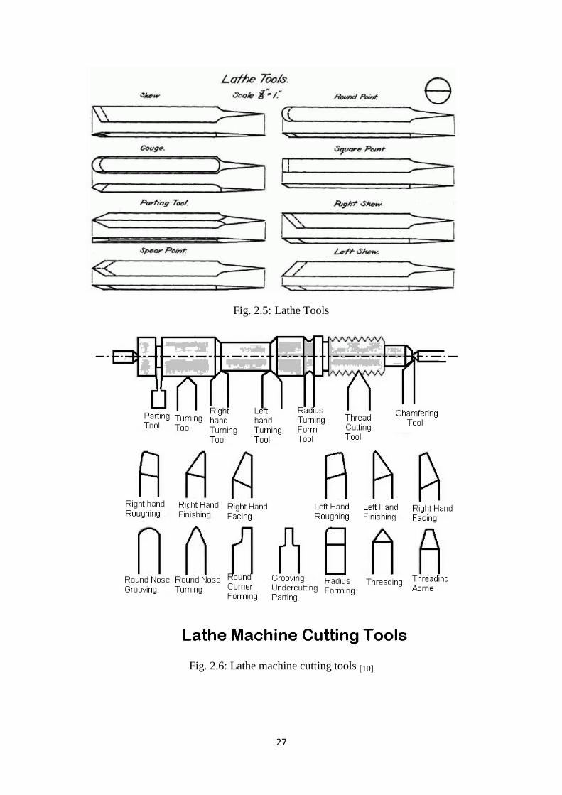
27
Fig. 2.5: Lathe Tools
Fig. 2.6: Lathe machine cutting tools [10]
28
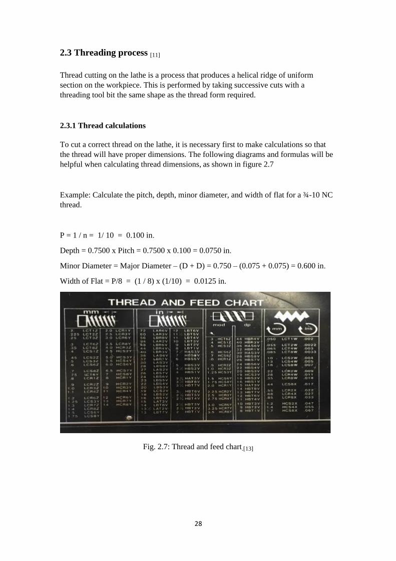
2.3 Threading process [11]
Thread cutting on the lathe is a process that produces a helical ridge of uniform
section on the workpiece. This is performed by taking successive cuts with a
threading tool bit the same shape as the thread form required.
2.3.1 Thread calculations
To cut a correct thread on the lathe, it is necessary first to make calculations so that
the thread will have proper dimensions. The following diagrams and formulas will be
helpful when calculating thread dimensions, as shown in figure 2.7
Example: Calculate the pitch, depth, minor diameter, and width of flat for a ¾-10 NC
thread.
P = 1 / n = 1/ 10 = 0.100 in.
Depth = 0.7500 x Pitch = 0.7500 x 0.100 = 0.0750 in.
Minor Diameter = Major Diameter – (D + D) = 0.750 – (0.075 + 0.075) = 0.600 in.
Width of Flat = P/8 = (1 / 8) x (1/10) = 0.0125 in.
Fig. 2.7: Thread and feed chart.[13]

29
2.3.2 Screw thread cutting [12]
Screw threads are cut with the lathe for accuracy and for versatility. Both inch and
metric screw threads can be cut using the lathe. A thread is a uniform helical groove
cut inside of a cylindrical workpiece, or on the outside of a tube or shaft. Cutting
threads by using the lathe requires a thorough knowledge of the different principles of
threads and procedures of cutting. Hand coordination, lathe mechanisms, and cutting
tool angles are all interrelated during the thread cutting process. Before attempting to
cut threads on the lathe a machine operator must have a thorough knowledge of the
principles, terminology and uses of threads, as shown in figure 2.8
Fig. 2.8: Screw thread terminology.
2.3.3 Screw thread terminology
The common terms and definitions below are used in screw thread work and will be
used in discussing threads and thread cutting, as shown in figure 2.9
External or male thread is a thread on the outside of a cylinder or cone.
Internal or female thread is a thread on the inside of a hollow cylinder or bore.
Pitch is the distance from a given point on one thread to a similar point on a
thread next to it, measured parallel to the axis of the cylinder. The pitch in inches
is equal to one divided by the number of threads per inch.
Lead is the distance a screw thread advances axially in one complete revolution.
On a single-thread screw, the lead is equal to the pitch. On a double-thread screw,
the lead is equal to twice the pitch, and on a triple-thread screw, the lead is equal
to three times the pitch.
Crest (also called "flat") is the top or outer surface of the thread joining the two
sides.

31
Root is the bottom or inner surface joining the sides of two adjacent threads.
Side is the surface which connects the crest and the root (also called the flank).
Fig. 2.9: Screw thread types
Angle of the thread is the angle formed by the intersection of the two sides of the
threaded groove.
Depth is the distance between the crest and root of a thread, measured
perpendicular to the axis.
Major diameter is the largest diameter of a screw thread.
Minor diameter is the smallest diameter of a screw thread.
Pitch diameter is the diameter of an imaginary cylinder formed where the width
of the groove is equal to one-half of the pitch. This is the critical dimension of
threading as the fit of the thread is determined by the pitch diameter (Not used for
metric threads).
Threads per inch is the number of threads per inch may be counted by placing a
rule against the threaded parts and counting the number of pitches in 1 inch. A
second method is to use the screw pitch gage. This method is especially suitable
for checking the finer pitches of screw threads.
A single thread is a thread made by cutting one single groove around a rod or
inside a hole. Most hardware made, such as nuts and bolts, has single threads.
31
Double threads have two grooves cut around the cylinder. There can be two, three,
or four threads cut around the outside or inside of a cylinder. These types of
special threads are sometimes called multiple threads.
A right-hand thread is a thread in which the bolt or nut must be turned to the
right (clockwise) to tighten.
A left hand thread is a thread in which the bolt or nut must turn to the left
(counterclockwise) to tighten.
Thread fit is the way a bolt and nut fit together as to being too loose or too tight.
Metric threads are threads that are measured in metric measurement instead of
inch measurement.
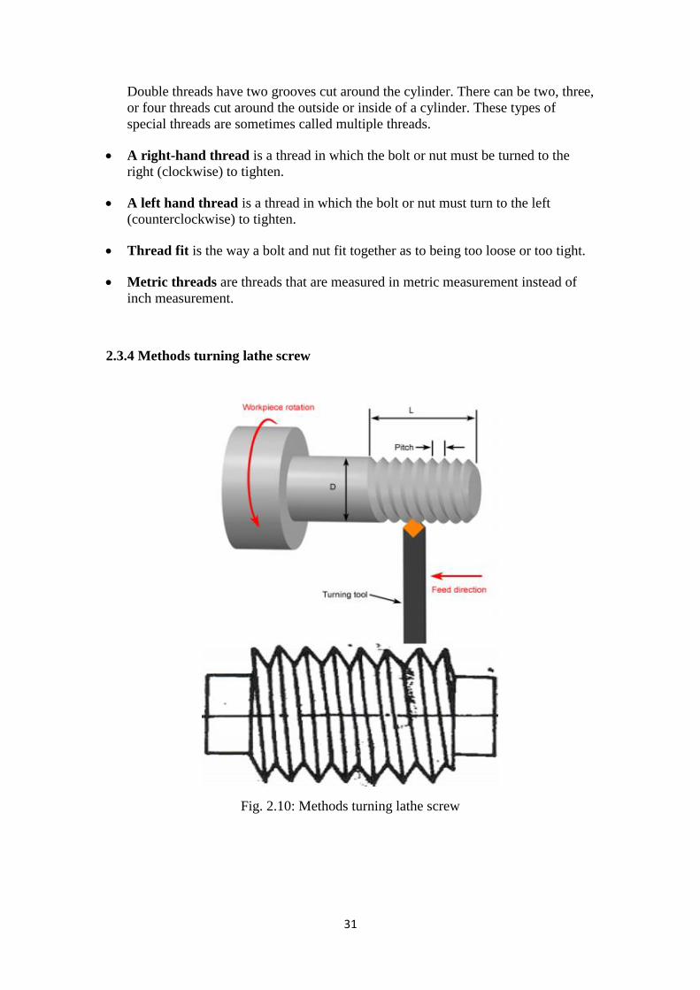
2.3.4 Methods turning lathe screw
Fig. 2.10: Methods turning lathe screw

32
There are several methods of turning thread on a lathe:
1. The conventional method
The conventional method is a method of movement threading with feeds (additional
incision depth / depth of cut), upright / using the cross slide.
2. Method slice one side
This threading method by tilting the top of the slide and use the top slide 60 as funeral
movement (depth of cut). This method is efficient for turning lathe the screw with a
large size, as shown in figure 2.11
Fig. 2.11: Thread cutting operation on lathe machine

33
Chapter 3: Components of machine
3.1 Introduction
In this chapter we will talk about the components of machine and explain its parts and
the function of each part.
This machine and parts were drawn using the SolidWorks software program.
3.2 Machine Parts
3.2.1 Machine Image
Fig. 3.1: Machine Image
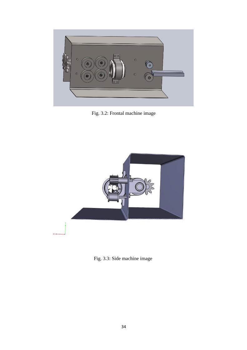
34
Fig. 3.2: Frontal machine image
Fig. 3.3: Side machine image
35
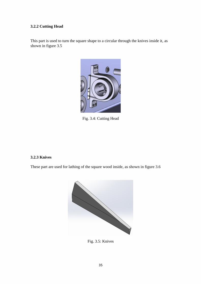
3.2.2 Cutting Head
This part is used to turn the square shape to a circular through the knives inside it, as
shown in figure 3.5
Fig. 3.4: Cutting Head
3.2.3 Knives
These part are used for lathing of the square wood inside, as shown in figure 3.6
Fig. 3.5: Knives
36
3.2.4 Knives Base
This part is used to carry the lathe knives, as shown in figure 3.7
Fig. 3.6: Knives Base
3.2.5 Base cutting head
This part is used to carry the cutting head, as shown in figure 3.8
Fig. 3.7: Base cutting head

37
3.2.6 Types of Bering
A. Feed Bearing
This part is used to push the wooden piece to the cutting head, as shown in figure 3.9
and 3.10.
Fig. 3.8: Feed Bearing
B. Output Bearing
This part is used to pull a cylindrical wood from the cutting head, as shown in figure
3.11.
Fig. 3.9: Output Bearing
38
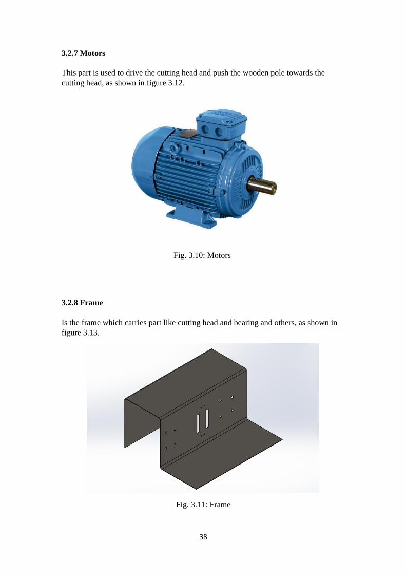
3.2.7 Motors
This part is used to drive the cutting head and push the wooden pole towards the
cutting head, as shown in figure 3.12.
Fig. 3.10: Motors
3.2.8 Frame
Is the frame which carries part like cutting head and bearing and others, as shown in
figure 3.13.
Fig. 3.11: Frame
39
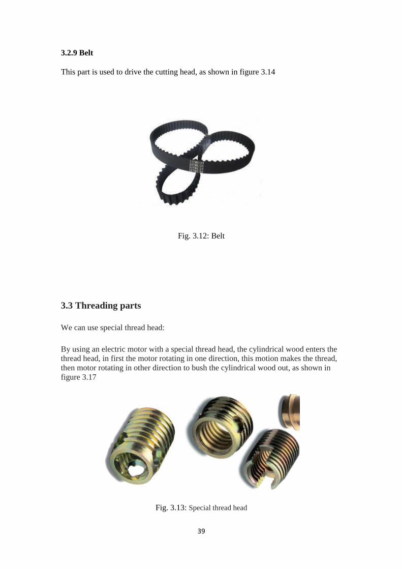
3.2.9 Belt
This part is used to drive the cutting head, as shown in figure 3.14
Fig. 3.12: Belt
3.3 Threading parts
We can use special thread head:
By using an electric motor with a special thread head, the cylindrical wood enters the
thread head, in first the motor rotating in one direction, this motion makes the thread,
then motor rotating in other direction to bush the cylindrical wood out, as shown in
figure 3.17
Fig. 3.13: Special thread head

41
Chapter 4: Machine design [14]
4.1 Introduction
Machine design is the most important part for any machine, so in this chapter the
mechanical design and electrical design for every part in the machine are detailed.
Before starting in mechanical design, the material and dimensions of the mechanical
part which will be designed must be known in addition to type of load and its material
properties to be on safe side.
4.2 Mechanical design
4.2.A Calculate the cutting or turning part of the wood pole
Fig. 4.1: Knife

41
Fig. 4.2: Wood pole and abraded part
Corrosion ratio from one side to the length in two dimensions:
= 0.025 cm
Corrosion ratio from both parties to the length in two dimensions:
0.025*2= 0.05 cm
Fig. 4.3: Wood cutting section
42
(1)
= ( )
(2)
=
= /cm (3)
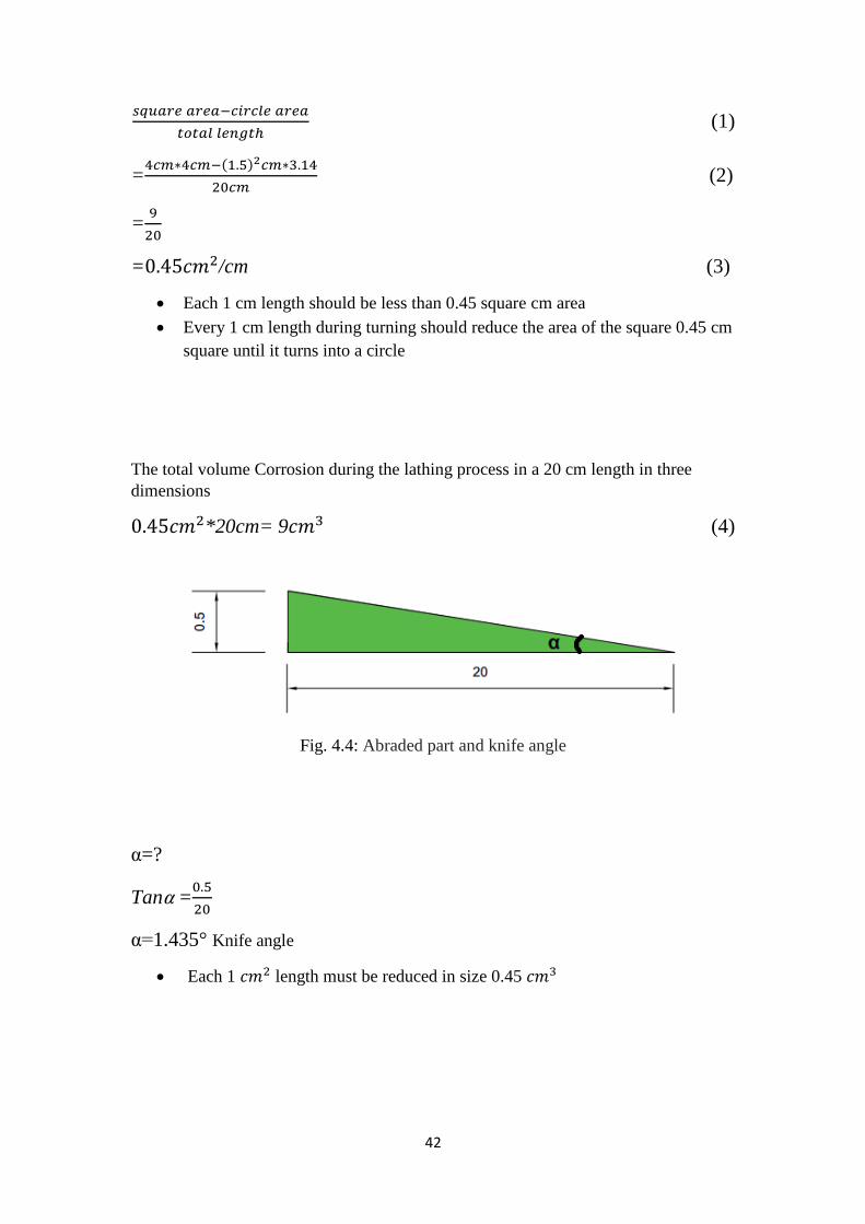
Each 1 cm length should be less than 0.45 square cm area
Every 1 cm length during turning should reduce the area of the square 0.45 cm
square until it turns into a circle
The total volume Corrosion during the lathing process in a 20 cm length in three
dimensions
*20cm= 9 (4)
Fig. 4.4: Abraded part and knife angle
α=?
Tan α =
=α 1.435° Knife angle
Each 1 length must be reduced in size 0.45

43
Fig. 4.5: Cutting volume
Y=> The circumference of a circle
=2*π*r (5)
=2*3.14*1.5
=9.42cm (6)
** I chose the perimeter of the circle because it is the least distance to be turning out
and It is the most common case in which the lathe is the Max Load on the knife
** X: Overlap knife with wood for lathing and required of knife to enter the depth X
for lathing.
Total volume= length* width* height (7)
= X * Y * 1cm
0.45 = X * 9.42 * 1 (8)
X=
X= 0.04778 cm
X=0.4778 mm (9)
** So, required of knives to enter the wood amount 0.4778mm
** So, the intersection of wood with the knife is 0.4778mm but it is divided into four
knives.
44
= 0.119mm/knife (10)
** Let us multiply safety factor 5
0.12*5 = 0.6mm >>> X=0.6mm (11)
** On the occasion of a malfunction in three knives one remained working the knife
must be lathe with safety therefore the safety factor 5
On the assumption we have 4 knives and at worst
4.2.B Find the relationship between the speed of the knife rotation and the speed
of the wood pole
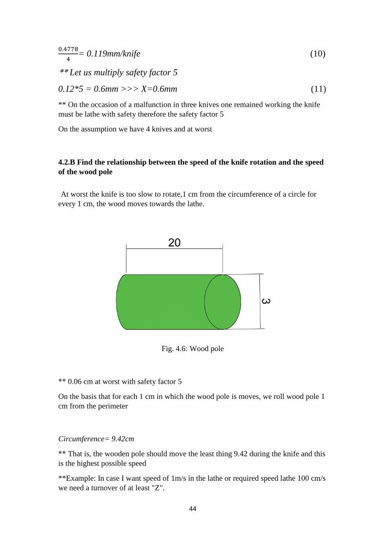
At worst the knife is too slow to rotate,1 cm from the circumference of a circle for
every 1 cm, the wood moves towards the lathe.
Fig. 4.6: Wood pole
** 0.06 cm at worst with safety factor 5
On the basis that for each 1 cm in which the wood pole is moves, we roll wood pole 1
cm from the perimeter
Circumference= 9.42cm
** That is, the wooden pole should move the least thing 9.42 during the knife and this
is the highest possible speed
**Example: In case I want speed of 1m/s in the lathe or required speed lathe 100 cm/s
we need a turnover of at least "Z".

45
** The Perimeter must intersect 1m/s at worst= 1m/s of wood length.
Circumference= 9.42 * Number of rolls in s = 100cm (12)
Number of rolls in s=
= 10.615 roll/s (13)
Z= 10.615 * 60s
Z= 636.9 ≈ 637 roll/min (14)
** In case we want a speed of lathing 1 m/s, the rotation should not be less than
637rpm for the knife ,and we conclude the velocity relation with the speed of the
wooden pole or the speed of the turning:
The speed of lathing m/s =
(15)
(16)
** This relationship is valid if we want to remove the volume of 0.45 cm3
For each cm, the wooden pole moves in it towards the knife of the lathe.
4.2.C Calculate the forces located on the lathe knife
** There are three Forces Influential on the knife we can take them into account:
1- The centrifugal force of the impact of rotation, and this force will not enter into the
calculations because there is a supportive of the knife eliminates the centrifugal force,
"action and reaction".
2- Bending Force & Bending Moment, the forces affecting the knife as a result of
turning "cutting force for turning wood"
** If the overlap is 0.6mm at worst and conditions the force required for lathing is
approximately 9 kg/mm
F= 9 * 9.8 (17)
=88.2 N/mm
≈ 90 N/mm (18)
46
**But the length of the knife is 200 mm
F=90*200
=18 KN
** The force required to cut part of wood 0.6 mm thickness along 20 cm.
** This force will be distributed to the four knives but we will take this force only on
one knife so as to calculate the worst conditions.
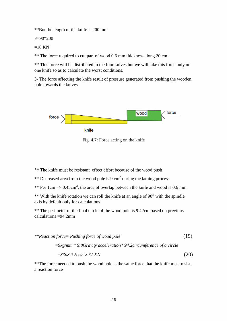
3- The force affecting the knife result of pressure generated from pushing the wooden
pole towards the knives
Fig. 4.7: Force acting on the knife
** The knife must be resistant effect effort because of the wood push
** Decreased area from the wood pole is 9 cm2 during the lathing process
** Per 1cm => 0.45cm2, the area of overlap between the knife and wood is 0.6 mm
** With the knife rotation we can roll the knife at an angle of 90° with the spindle
axis by default only for calculations
** The perimeter of the final circle of the wood pole is 9.42cm based on previous
calculations =94.2mm
**Reaction force= Pushing force of wood pole (19)
=9kg/mm * 9.8Gravity acceleration* 94.2circumference of a circle
=8308.5 N ≈> 8.31 KN (20)
**The force needed to push the wood pole is the same force that the knife must resist,
a reaction force

47
4.2.D Calculate knife properties
** The knife is made of ordinary iron to calculate the thickness of the knife, of course
the selected knife will be stronger than ordinary iron, only here will we calculate its
thickness
**cutting force for wood for our machine is 18kN
(21)
=
=
=
=
=955414 N/m
2 (22)
** knife will not stand out more than 5 mm from the knife carrier cylinder
Fig. 4.8: Knife and stand out
48
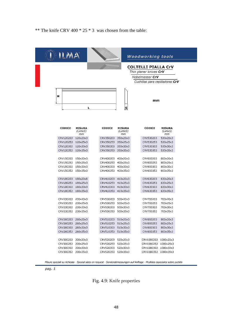
** The knife CRV 400 * 25 * 3 was chosen from the table:
Fig. 4.9: Knife properties

49
** Because available in the market is a special knife for cutting wood or work wood
carpentry from wood and trees and we will make the necessary calculations to make
sure that the knife is suitable for the case of our machine.
Fig. 4.10: Force acting on the knife
** E=200Gpa
I=second moment of inertia
I=
= ( )
= 4.5*10
-10 = 0.45*10
-9 (23)
standard case bending
Deflection=
=
( )
=0.005mm (24)
Fig. 4.11: Deflection on the knife

51
The result:
* The knife is very successful to work
* We will buy the knife length 40 cm and cut it by half
* The selected knife can resist the shear arising from the lathe
* Compared to the previously calculated shear amount
And the shear, which can be resisted by the knife in the knife characteristics table:
" The knife is successful for calculating"
1- Deflection or Bending
2- Shear
3- Force:
A- Horizontal
B- Vertical
4- Centrifugal Force
4.2.E Calculate the pressure on the wood pole to push the pole toward the knives
There are two cases in push:
1- Push in between the two wheels in the case of the Square
2- When the pole arrives to the next two wheels after turning in the case of a cylinder
1- Friction should be generated between the two wheels at first to push the square-
shaped wood pole into the lathe
" Based on calculations of the forces necessary for lathing, previously"
Reaction force F ≈8310N
Friction force ≤ Reaction force
So that can continue to move
** The force is very large so we will have to reduce it by reducing the eroded part of
the wood in the lathing process Through a higher speed in the lathing and less speed
in the pole move.
** Let's make it Interference between the wood pole and the knife:

51
Instead of 0.6mm we make it 0.1mm
so instead of 9Kg/mm => 9*
=> 1.5Kg/mm (25)
F On the knives= 1.5*9.8*200=2.94KN (26)
F reaction=1.5*9.8*94.2 perimeter=1.385KN (27)
** The forces are distributed on four knives
F Single knife=
=0.735KN (28)
F reaction single knife=
= 0.346KN (29)
ℳs: Coefficient of static friction
ℳs Iron and wood ≈ 0.3→ 0.6
ℳs Wood and rubber ≈1
"So we will choose rubber with wood"
** It was selected ℳs not ℳx on the basis that there is no slipping between the wood
and the wheel
** It was selected ℳs between wood and rubber because it is the largest friction
coefficient
Friction= ℳs*mg (30)
= ℳ s *2N => 1*2=2N (31)
F reaction= Friction=0.346KN=2N
N >
=
N >173N
** N: Is the force needed to squeeze the wheel to generate friction
"N is produced from the spring"
N=K Δ X
Δx: Amount of pressure
K: constant spring
52
Let's make it Δx=3cm
173=K*0.03
K1=5767N/M
For safety we choose =>6KN/M
** In the case of rotary or cylindrical wheels, the force needed to move the wood pole
is distributed on the wheels in the beginning and the wheels in the end after the
lathing
**K2: Constant spring for cylindrical wheels
K2=3KN/M " Because the forces are evenly distributed between the wheels"
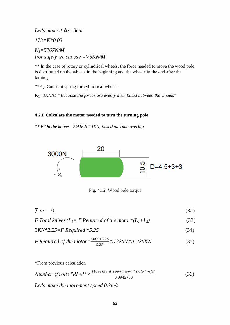
4.2.F Calculate the motor needed to turn the turning pole
** F On the knives=2.94KN ≈3KN, based on 1mm overlap
Fig. 4.12: Wood pole torque
∑ (32)
F Total knives*L1= F Required of the motor*(L1+L2) (33)
3KN*2.25=F Required *5.25 (34)
F Required of the motor=
≈1286N ≈1.286KN (35)
*From previous calculation
Number of rolls "RPM" ≥
(36)
Let's make the movement speed 0.3m/s

53
Number of rolls "RPM" ≥
=191 RPM (37)
** So required motor 200 RPM at least
**and F=1.286 KN at least
** Every 3.33 seconds the machine is lathe 1m of the wood pole
** Diameter of pulley cutting head and motor pulley
Fig. 4.13: Diameter of pulley cutting head and motor pulley
*F Required of the motor on the cutting head =
* ≈ 0.88KN (38)
*The rotation speed itself is 200 RPM
* F Required of the motor on the motor pole=
*0.88≈ 0.3KN (39)
* Torque of our motor= F*r = F*D/2 (40)
=0.3KN*0.025= 7.5N/M (41)
* Based on we put the motor 1500RPM
lathing pole speed=
=500RPM (42)
"So, you need to put an inverter to control the speed"
*1N.M/S = 0.1 KW
54
*7.5= 0.75KW
* But we have friction between the pulley and inertial in the turning pole because it is
large and friction in the chain
* So, we will put a safety factor=3 to enable the motor of working in extreme cases.
* Motor required=0.75KW*3= 2.25KW (43)
Motor required ≥ 3 H.P (44)
* Based on the motor works on 220V
*Power=I*V (45)
3H.P=2250W=I*220
I=10.3 A (46)
* Wire clip area required to connect the current to the motor =1.03 mm2
So, we will choose a wire with a area of 1.5 mm2
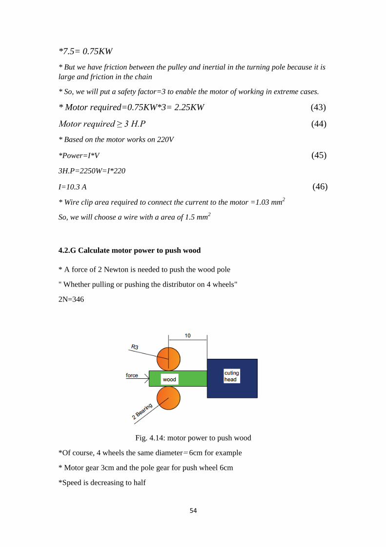
4.2.G Calculate motor power to push wood
* A force of 2 Newton is needed to push the wood pole
" Whether pulling or pushing the distributor on 4 wheels"
2N=346
Fig. 4.14: motor power to push wood
*Of course, 4 wheels the same diameter= 6cm for example
* Motor gear 3cm and the pole gear for push wheel 6cm
*Speed is decreasing to half

55
* Motor with gear slows down speed
* push motor 1500 RPM
*Gear box=
= 150 RPM (47)
* The difference between the diameter of the motor pole and diameter of the wheel
pole is 6cm → 3cm
=75 RPM
=1.25 Roll per second
*But the diameter of the wheel is 6cm = perimeter =6*π=18.84
*18.84= 23.55cm/s= 0.23 m/s
*slow, so we will increase speed twice by making the wheels or wheels pole gear
equal to the gear of the motor pole with gear
*Speed of turning=23.55*2= 47.1cm/s
=0.471m/s appropriate
*Because we put 1→10 gear box
*Torque on the motor decreases by 10 times
* Torque is required from the motor is
=34.6N
* Torque= F*R= 34.6*3cm " Radius of rubber wheels" (48)
=34.6*0.03m =1.038NM (49)
* We have friction between the gears so we will multiply the inertial:
F.O.S * 4 = 1 H.P
"Needed motor with gear box 1/10"
56
4.2.H Buckling
*FKN=
(50)
E=12.5 GPA
I=
= ( )
=21.33 mm
4 (51)
Fig. 4.15: Buckling
*FKN=( )
=36.973KN (52)
* It Can bear buckling compared with 2N
4.2.I Torsional shear stress
τ=
(53)
J=
= ( )
= 79481.25 (54)
T=7.5*3=22.5 From previous calculation
τ=
= 4.245MPA (55)
=
=
57
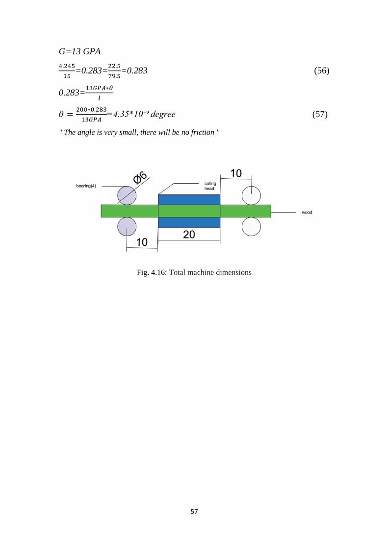
G=13 GPA
=0.283=
=0.283 (56)
0.283=
=4.35*10⁻⁹ degree (57)
" The angle is very small, there will be no friction "
Fig. 4.16: Total machine dimensions
58
4.2.J Belt drive selection "V-Belt"
Note: All tables and attachments are attached in the appendix section
1500 rpm for fast shaft, 500 slow shaft, Hnom=2.25 KW
Speed ratio =
=
= 3 (58)
Design power :
From table 17.6 ** find Ks
Ks* =1.2
Multiply Ks* by 1.18 Speed ratio effect:
Ks = 1.418
Nd =1
Hd = Ks*Nd *Hnom (59)
= 1,416 * 1 * 2.25
=3.186 Kw
From figure 17.1a ***** with speed 1500rpm, power 3.186
We select the belt A or AX.
We chose belt A
Sheaves:
(60)
60 mm
From table 17.5 for A section with SR= 3
D= 224mm d =75mm

59
Design power Hr :
Hr =Hbiss + Hadd (61)
From table 17.7 a with N=1500 rpm , d=75 ,SR =3
Hbiss= 1.07 Kw Hadd=0.28Kw
Hr = 1.35Kw
Specify a center distance:
( ) (62)
( )
Use C = 560 mm
Lp = 2C +
( )
( )
(63)
Lp=1600mm
From table 17.1a:
Li to Lp =36mm
Li to La = 50 mm
Li= Lp – 36 = 1563mm
La = 1550 mm
From table 17.2 a:
We chose A60 with Li =1524 mm
Lp = Li + 36
= 1560mm
C=0.24{(Lp-
( )) (
( ) ( ) ) (64)
= 519.5 mm
=0.286 (65)
From Table 17.8
K1= 0.96
From table 17.9
K2 =0.98
Ha =K1*K2*Hr (66)

61
=0.96*0.98*1.35 Kw
= 1.27Kw
Number of belt :
Nb =
(67)
= 1.77
Therefor select Nb =2 belt
Belt tensions:
V=
(68)
= 5.8 m\s
T1 = ( )
( ) =238.7 N (69)
T2 =
( ) = 647.2 N (70)
Ti =
= 442.9 N (71)
Minimum allowance:
From table 17.3 a with Lp = 1560
X= 25 mm Y=20 mm
Drive shaft load
√ ( ) (72)
Fa = 885.9 N

61
Summary of belt design:
Input: Ac-motor, 2.25Kw ,1500 rpm
Serves factor Ks = 1.416
Design power = 3.186 Kw
Belt: A60, 2 belt
Sheaves: Driver 75 mm one grove
Driven 224 mm one grove
Center distance: 520 mm
Belt tensions: T1 = 238.7 N T2=647.2 N Ti=442.9 N
Minimum allowance: X=25mm y=20 mm
Driving shaft load = 885.89 N

62
4.2.k To calculate the deflection:
Fig. 4.17: Calculate the deflection
K=√
(73)
=√
= 0.57mm
Where:
K: radius of gyration
I: second moment of area
A: area
4.2.L To calculate Buckling
(74)
= ( )( ) ( )( )
( )
Where:
Pcr: Buckling
C: the effective length factor
I: second moment of area

63
E: modulus of elasticity
L: length
4.2.M To calculate maximum normal stress:
[
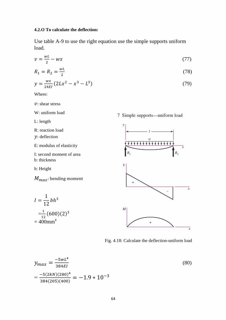
[
√
]] (75)
=
[
( )
( ) [
]]
=3.56 MPa
Where:
P: load
A: area
k: radius of gyration
e: Eccentric Loading
C: the effective length factor
Buckling
4.2.N To calculate the deflection:
* (
√
) + (76)
Where:
Buckling
P: Load
64
4.2.O To calculate the deflection:
Use table A-9 to use the right equation use the simple supports uniform
load.
(77)
(78)
( ) (79)
Where:
shear stress
W: uniform load
L: length
R: reaction load
deflection
E: modulus of elasticity
I: second moment of area
b: thickness
h: Height
=
( )( )
= 400mm4
Fig. 4.18: Calculate the deflection-uniform load
(80)
= ( )( )
( )( )

65
V=0.0 when (L/2)
( )
( )( )
( ) (81)
4.2.P To calculate the shear:
Where:
W: uniform load
X: length
V:shear force
maximum shear stress
( )( )
(82)
=0.0
Principle stress ( ) ( )
( )( )
( )
( )( ) (83)

66
4.2.Q To calculate the energy:
Where:
U: energy
G: modulus of rigidity
E: modulus of elasticity
I: second moment of area
C=1.2 rectangular
G for 1023 carbon steel =80 Gpa
E for 1023 carbon =140 Gpa
(84)
=
= ( )( )
( ) ( )
( )( )
( )( )
= 0.025 + 0.49
U= 0.55 J
4.2.R To calculate the shear in shaft:
Where:
maximum shear stress
T: Torque
C: radius
J: second polar moment of area
yielding strength
yield shear strength
67
(85)
Carbon steel A36
Sy=240 MPa
( ) ( )
Assume (Motor):
T=1.5 KN.m
( ) ( )
=1.884

68
4.3 Electrical design
4.3.A Motors
An electric motor is an electrical machine that converts electrical energy into
mechanical energy. In this section electrical motors specifications which includes AC
motors and DC motors will be explained, where motors selection was based on the
application of each motor:
1- Rotating motor:
The motor will rotate the cutting head through the belt and has the following
specifications, Table 4
Table 4: Rotating motor specifications
Specifications Value Unit
Power 3 Horse Power (HP)
Rated Voltage Y/Δ 380/220 Volt
Frequency 50 Hertz (Hz)
Rated current Y/Δ 9.86/5.7 Ampere
No load speed 1500 r/min
2- Push motor:
The motor will push the wooden pole through the push pulley and has the following
specifications, Table 5
Table 5: Push motor specifications
Specifications Value Unit
Power 0.5 Horse Power (HP)
Rated Voltage Y/Δ 380/220 Volt
Frequency 50 Hertz (Hz)
Rated current Y/Δ 1.27/2.2 Ampere
No load speed 200 r/min
69
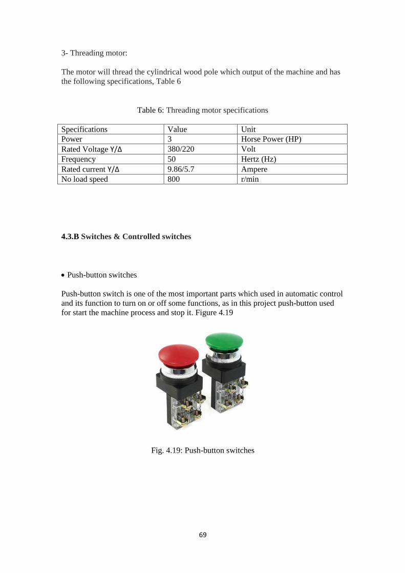
3- Threading motor:
The motor will thread the cylindrical wood pole which output of the machine and has
the following specifications, Table 6
Table 6: Threading motor specifications
Specifications Value Unit
Power 3 Horse Power (HP)
Rated Voltage Y/Δ 380/220 Volt
Frequency 50 Hertz (Hz)
Rated current Y/Δ 9.86/5.7 Ampere
No load speed 800 r/min
4.3.B Switches & Controlled switches
Push-button switches
Push-button switch is one of the most important parts which used in automatic control
and its function to turn on or off some functions, as in this project push-button used
for start the machine process and stop it. Figure 4.19
Fig. 4.19: Push-button switches

71
Contactors
A contactor is an electrically controlled switch used for switching an electrical power
circuit. A contactor is typically controlled by a circuit which has a much lower power
level than the switched circuit. Figure 4.20
Contactors come in many forms with varying capacities and features. Unlike a circuit
breaker, a contractor is not intended to interrupt a short circuit current. Contactors
range from those having a breaking current of several amperes to thousands of
amperes and 24 V DC to many kilovolts.
Contactors are used to control electric motors, lighting, heating, and other electrical
loads.
Fig. 4.20: Contactors
4.3.C Variable Frequency Drive (VFD) or "inverter”
Variable-frequency drive (VFD); also termed variable speed drive, or "inverter” drive
is a type of adjustable-speed drive used in electromechanical drive systems to control
AC motor speed and torque by varying motor input frequency and voltage.
VFD shown in Figure 4.21 used in this machine to control the speed of the lathe
motor and the speed of the motor drive the wood pole
Fig. 4.21: Inverter
71
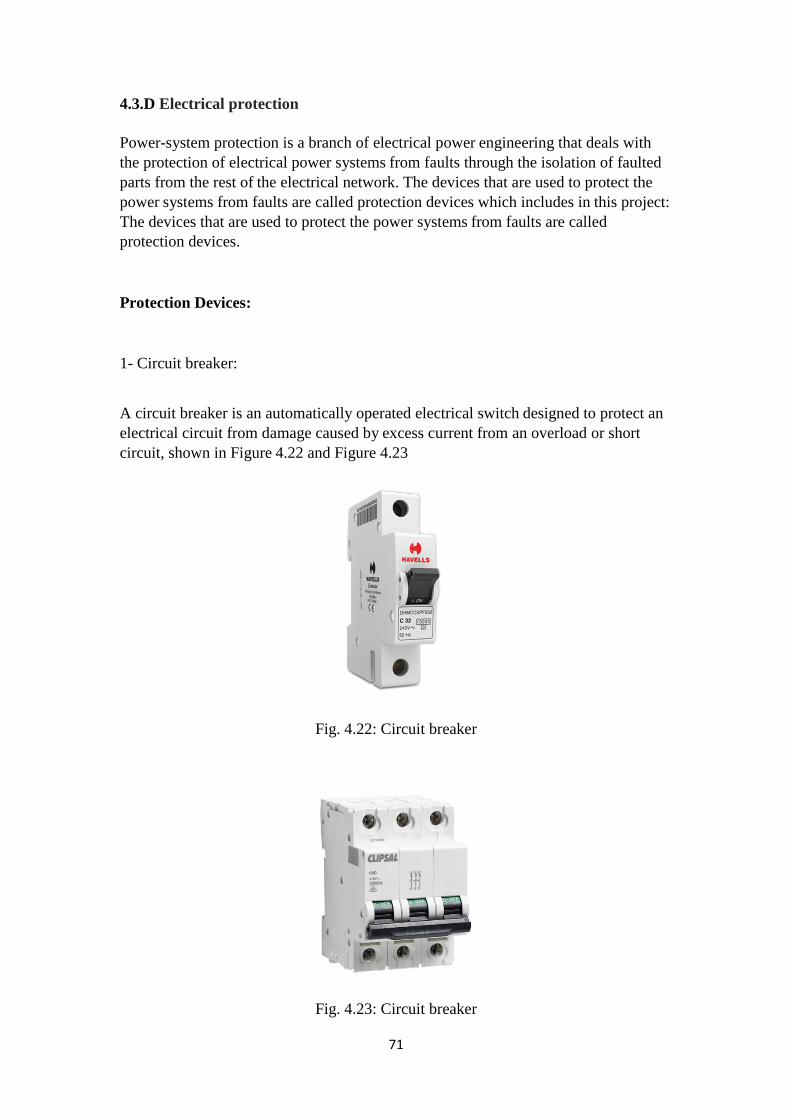
4.3.D Electrical protection
Power-system protection is a branch of electrical power engineering that deals with
the protection of electrical power systems from faults through the isolation of faulted
parts from the rest of the electrical network. The devices that are used to protect the
power systems from faults are called protection devices which includes in this project:
The devices that are used to protect the power systems from faults are called
protection devices.
Protection Devices:
1- Circuit breaker:
A circuit breaker is an automatically operated electrical switch designed to protect an
electrical circuit from damage caused by excess current from an overload or short
circuit, shown in Figure 4.22 and Figure 4.23
Fig. 4.22: Circuit breaker
Fig. 4.23: Circuit breaker
72
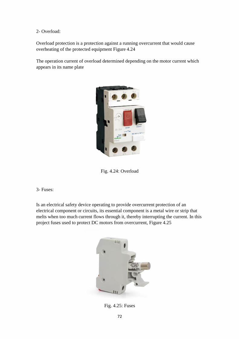
2- Overload:
Overload protection is a protection against a running overcurrent that would cause
overheating of the protected equipment Figure 4.24
The operation current of overload determined depending on the motor current which
appears in its name plate
Fig. 4.24: Overload
3- Fuses:
Is an electrical safety device operating to provide overcurrent protection of an
electrical component or circuits, its essential component is a metal wire or strip that
melts when too much current flows through it, thereby interrupting the current. In this
project fuses used to protect DC motors from overcurrent, Figure 4.25
Fig. 4.25: Fuses

73
4- Emergency stop:
Emergency stop is a normally closed switch used to stop the machine process in
emergency situations to protect human and machine parts from any danger or damage,
Figure 4.26
Fig. 4.26: Emergency stop
4.3.E Lamp
The lamp is used in our machine to know if there is an over-load on the motor to stop
it or in case of pressing the emergency.
and to prove the work of the lathe motor, and to prove the work of the motor push the
wood pole, Figure 4.27.
Fig. 4.27: Lamp

74
4.3.F Wiring diagram (power and control circuit)
Control circuit
P.P1 NC: Red button to turn off the lathe motor
P.P2 NO: Green button to turn on the lathe motor
P.P3 NC: Red button to stop the engine pulling the wood pole
P.P4 NO: Red button to turn on the motor pushing the wood pole
A1: Turning Contactor 220V AC

75
A2: Motor contactor pushing the wood pole 220V AC
Lamp(1): To know if there is an over-load on the motor to stop it or in case of
pressing the emergency.
Lamp(2): To prove the work of the lathe motor.
Lamp(3): To prove the work of the motor push the wood pole
Power circuit
(1) Speed control: Inverter 3 H.P to speed control lathe motor
(2) Speed control: Inverter to speed control of the push motor the wood pole
76
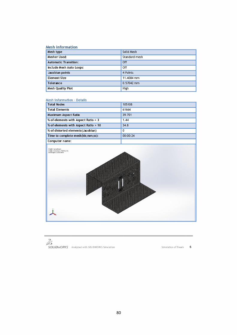
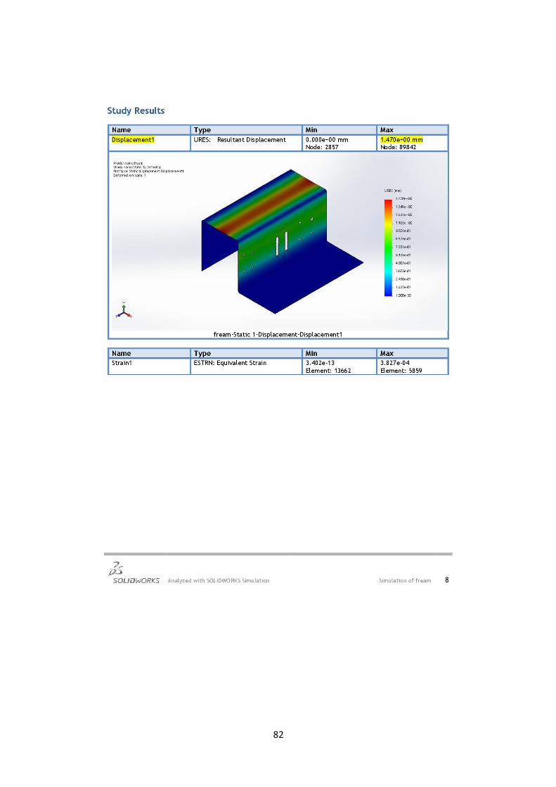
Chapter 5: Simulation of frame and shaft
5.1 Simulation of frame

77

78

79
81

81
82
83

84
85
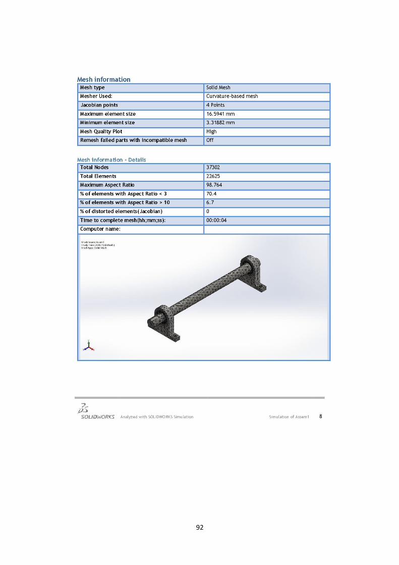
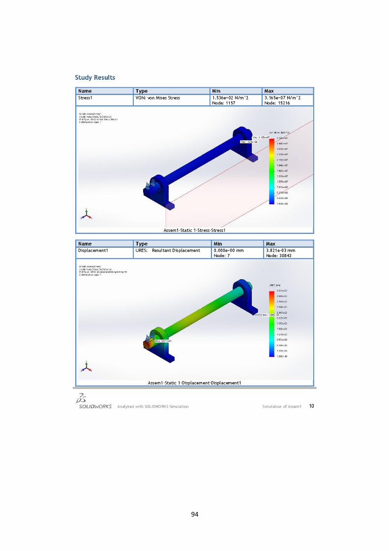
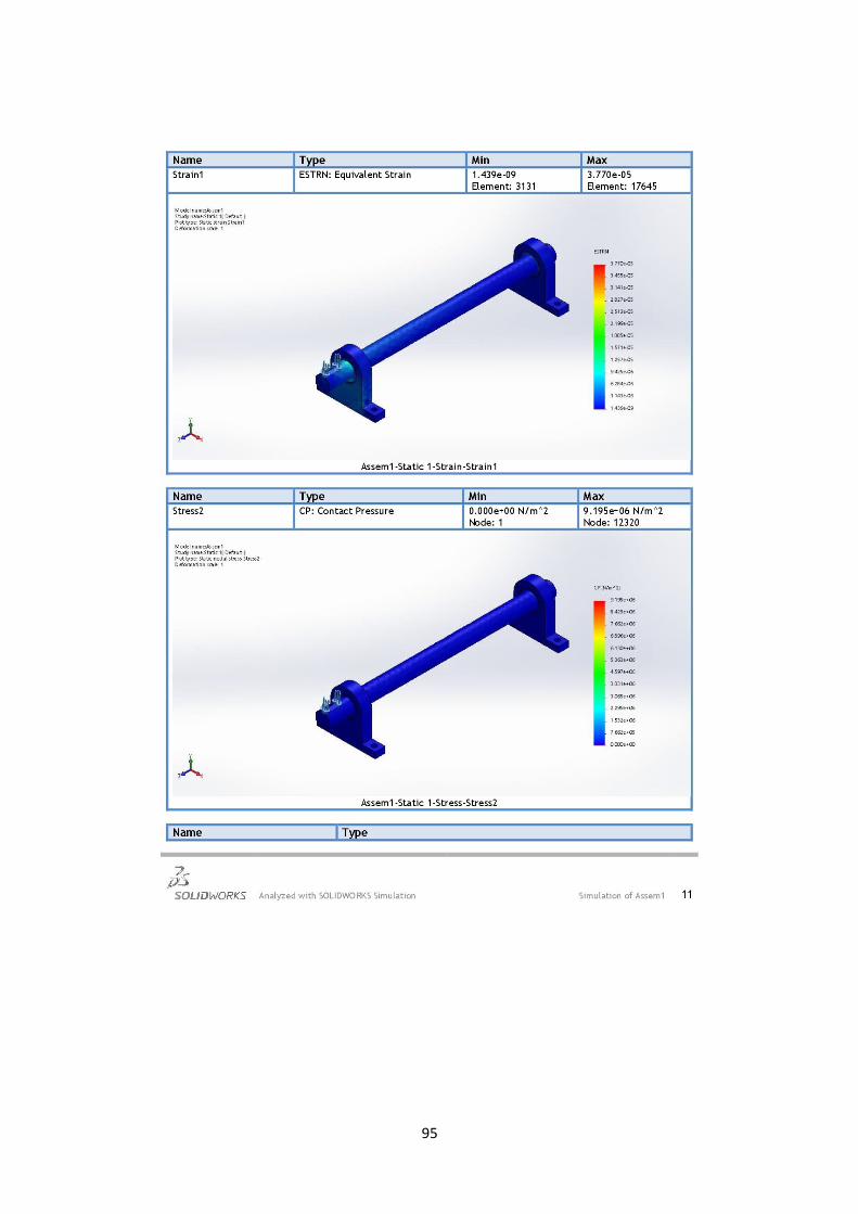
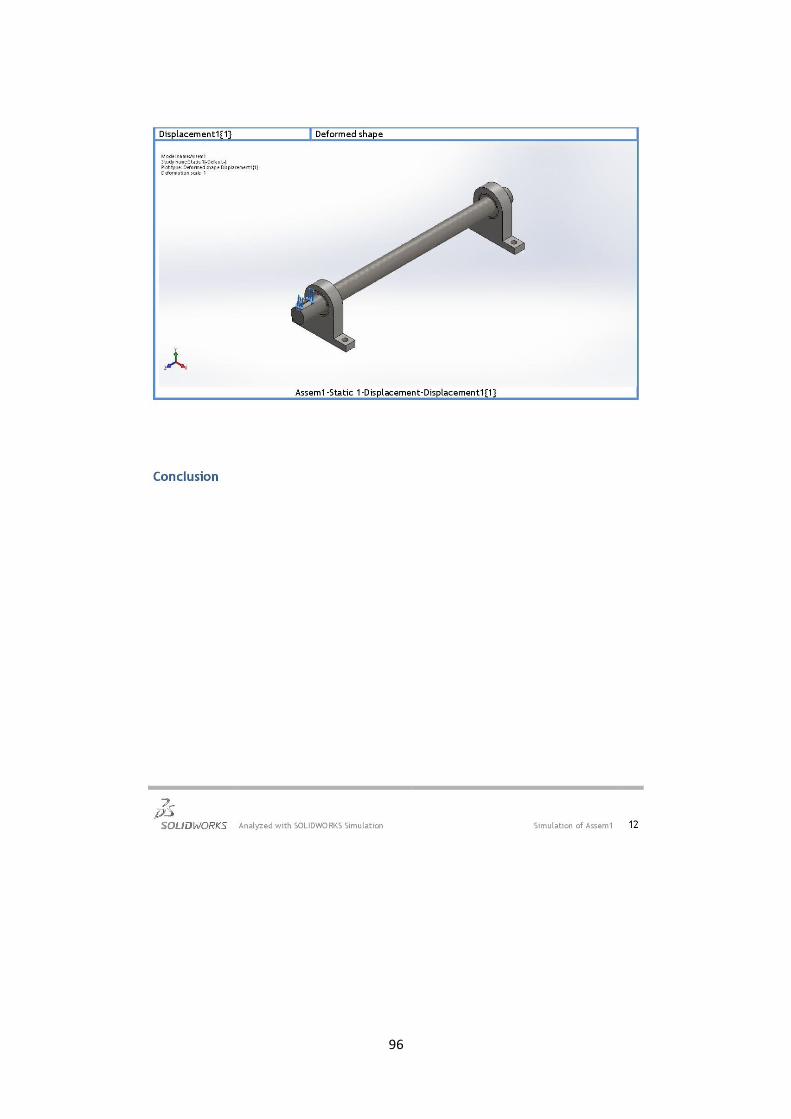
5.2 Simulation of shaft

86
87
88

89

91

91
92

93
94
95
96
97
Chapter 6: Conclusions and recommendations
6.1 Conclusions
In this school year we were collected information, ideas and previous studies related
to the idea of the project, and we drawn all parts of the project on the SolidWorks
program and AutoCAD and created a proposed design to implement the required
machine.
Then, we worked out calculations of mechanical and electrical design, to buy the
machine parts and lathing the parts, and simulation to knowledge of the strengths and
weaknesses of the machine and then then we started the process of assembling and
building the machine based on the proposed design and calculations.
Knowing that will produce ready-to-use broom sticks to reduce imports, lower prices
and produce a high-quality local product at a longer life.
6.2 Recommendations
The purpose of any project is continuity and develop the project, in this section
recommendations suggested for this aim specially for those whom will work on the
project in future, includes:
* The main problem we faced during implementing the project was find a lathe to turn
the cutting head and was in obtaining some of the parts of the project.
* The university should provide the proper toolsets, which enable the student to
assemble his project and to test it which will get benefit of experiences in the
university.
* Make the machine automatically by adding PLC or Microcontroller and programing
* Change the specifications of the machine product as needed by changing the cutting
head specifications

98
Appendix
A.1: V-belt service factors, Ks
A.2: Selection chart for classical V-belts cross section
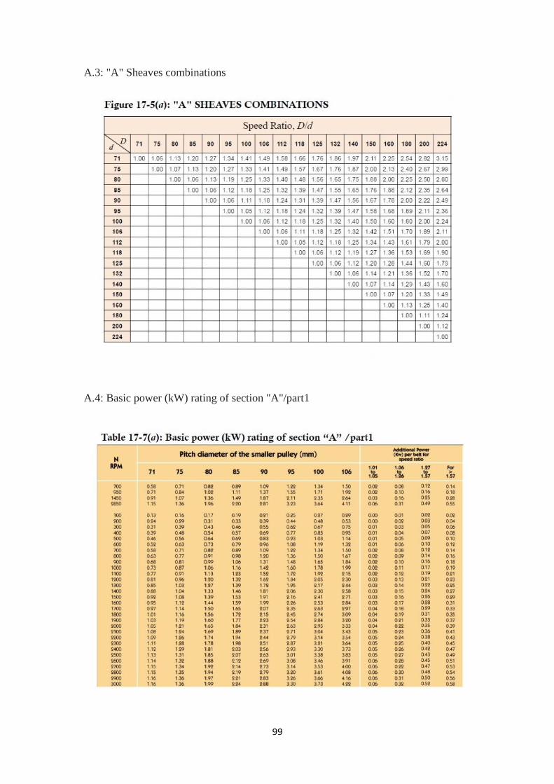
99
A.3: "A" Sheaves combinations
A.4: Basic power (kW) rating of section "A"/part1
111
A.5: Standard V-belt sections
A.6: Standard length of classical section, A

111
A.7: Angle of contact correction factor, K1
A.8: Belt length correction factor, K2

112
A.9: Minimum allowance
113
References
1. Carey, T.J., Wooden broom assembly and adapter means therefor. 1993,
Google Patents.
2. Congdon, J.L., Universal rotation-inhibiting connector apparatus and
method for threaded utility handles. 2010, Google Patents.
3. Keshav, G. and M. Damodaran, Design and Prototyping of a Low-Cost
Manually Operated Bamboo-Cored Incense-Stick Making Machine. 2013.
4. Lewis Jr, J.C., Handle socket adapter. 1987, Google Patents.
5. Nichols, C. and J. Howard, Broom having interlocking components. 1987,
Google Patents.
6. Spinelli, E., Modular handle, particularly for brooms and like. 2005, Google
Patents.
7. Conover, E., The Lathe Book: A Complete Guide to the Machine and Its
Accessories. 2001: Taunton.
8. Milton, A.S. and O.K. Wohlers, A Course In Wood Turning. 1919: Bruce
Publishing Company.
9. Raffan, R., Turning Wood with Richard Raffan. 2008: Taunton Press.
10. https://www.theengineerspost.com/lathe-machine-operations/
11. http://machiningtool.blogspot.com/2014/09/turning-thread-on-lathe.html
12. https://smithy.com/machining-handbook/chapter-3/page/24
13.
https://openoregon.pressbooks.pub/manufacturingprocesses45/chapter/un
it-6-lathe-threading
14. Richard G. Budynas, J. Keith Nisbett, Shigley's Mechanical Engineering
Design, October 25, 2006


