i
Design and Development of Automated Filler
Rod Feeding System for TIG Welding
Ranbir Pratik Pradhan
(111ME0336)
Department of Mechanical Engineering
National Institute of Technology Rourkela
Rourkela-769008
Odisha,India
ii
Design and Development of
Automated Filler Rod Feeding System
For TIG Welding
A Thesis Submitted for Partial Fulfilment
Of the Requirements for the degree of
Bachelor of Technology
In
Mechanical Engineering
By
Ranbir Pratik Pradhan
Roll: 111ME0336
Under the Supervision of
Prof. Manoj Masanta
Department Of Mechanical Engineering
National Institute Of Technology Rourkela
Rourkela-769008
Odisha, India

iii
CERTIFICATE
This is to certify that the work in the thesis entitled Design and Development
of Automated Filler Rod Feeding System for TIG Welding by Ranbir Pratik
Pradhan (111ME0336), has been conducted under my supervision required for
partial fulfilment of the requirements for the degree of Bachelor of Technology
in Mechanical Engineering during session 2014-2015 in the Department of
Mechanical Engineering, National Institute of Technology, Rourkela.
To the best of my knowledge, this work has not been submitted to any other
University/Institute for the award of any degree or diploma.
Date Prof. Manoj Masanta
(Supervisor)
Assistant Professor
Place-Rourkela Department of Mechanical Engineering
National Institute of Technology, Rourkela

iv
ACKNOWLEDGEMENT
First and foremost, I am thankful to the Almighty, without whose blessings this
project would not have seen his completion.
My sincerest gratitude goes to my supervisor Prof. Manoj Masanta for his
stimulating support. He has constantly given me opportunities to question my
limits and has supported me throughout my thesis work with his constant
encouragement and unwavering patience. I am highly indebted to him for
taking out his precious time and guiding me through the proper channel.
I would also like to extend my thanks to the faculty members of Mechanical
Engineering Department for imparting invaluable knowledge and aiding in the
value-oriented growth of my career. I am highly grateful to the staff and
members of Central Workshop for their greatly needed technical support in
giving shape to the model.
Above all, I am blessed to have such caring parents who have given me full
freedom to fulfil my dreams and have always supported in my decisions. I
extend my deepest gratitude to my family members and friends for their
immense love, affection, encouragement and support.
Last but not the least; I will always remain indebted to my project partner Patil
Gagan Shivadas who has stood with me through every hurdle and obstacle and
never lost confidence in me. This project wouldn t have come into being
without him.
Ranbir Pratik Pradhan

v
DECLARATION
This is hereby solemnly and sincerely declared that the project and the thesis
entitled Design and Development of Automated Filler Rod Feeding System
for TIG Welding is a result of the combined effort of Ranbir Pratik Pradhan
(111ME0336) and Patil Gagan Shivadas (111ME0348) of the Department of
Mechanical Engineering, National Institute of Technology, Rourkela.
Prof. Manoj Masanta Patil Gagan Shivadas
(Supervisor) 111ME0348
Assistant Professor
Department of Mechanical Engineering
Ranbir Pratik Pradhan
111ME0336

vi
ABSTRACT
Tungsten Inert Gas welding is a very effective welding process widely used in many
industries for joining of sheets, stainless steel pipes, automobile parts and many other
manufacturing processes. This welding process has an additional advantage of protecting
the weld bead with the help of shielding gas or inert gas which avoids the oxidation of the
bead, making the joint wear resistant and slag free. This has increased the demand of TIG
welding extensively. Generally, it is done manually by holding filler rod in one hand and the
TIG torch with other. Thus, the process requires a high amount of skill and human labour.
Automation of TIG welding will not only reduce human labour but also improve accuracy.
The project aims to develop and design an automated filler rod feeding system for TIG
welding. To fulfil this purpose, a number of mechanisms are considered namely rack-pinion
mechanism, slider-crank mechanism and screw-nut mechanism. The advantages and
limitations of each mechanism are weighed against each other to decide the best
mechanism that can be implemented. The mechanism is then designed and fabricated so as
to fulfil the objectives of the project. It has also been ensured that the product at the
completion of this project is industry oriented and has commercial value. After a rigorous
analysis of the different mechanisms possible, screw and nut mechanism was chosen to be
fabricated. A screw was made to rotate along a nut with the help of a motor. The motor
shaft is fastened to the screw with the help of universal couplers. The filler rod is fixed to
the screw with the help of a filer rod holder which is basically a cylindrical clamp. A slider is
also provided to aid the movement of the motor with the screw. Finally, the whole setup is
assembled on a Portable Moving Tractor, to which the TIG torch is also secured. The feeding
of the filler rod is coordinated with the movement of the TIG torch. The suggested
mechanism is one of its first in this particular field and can prove to be a worthy
replacement of the presently used wire-feeding arrangement. With proper research in this
area, it can be expected that better mechanisms and arrangements will emerge or
materialize.

vii
CONTENTS
Item Page No.
Chapter-1: Introduction
1.1 TIG Welding 1
1.2 TIG Welding Setup 2
Chapter-2: Background Study
2.1 Literature Review 4
2.2 Motivation 7
2.3 Objectives 7
Chapter-3: Methodology
3.1 Experiments Conducted 8
3.2 Feeding Mechanisms 10
Chapter-4: Results and Discussion 15
Final Assembly 20
Chapter-5: Conclusions and Future Scope 21
Bibliography 23

viii
LIST OF FIGURES
1.1 TIG Welding Setup . . . . . . . . 2
3.1 Portable Moving Tractor (PMT) . . . . . . 8
3.2 Slider Crank Mechanism . . . . . . . 11
3.3 Rack and Pinion Mechanism . . . . . . 13
3.4 Screw and Nut Mechanism . . . . . . 14
3.5 Screw and Nut Mechanism . . . . . . 14
4.1 Coupler . . . . . . . . . . 15
4.2 Motor coupled to the screw . . . . . . 16
4.3 Slider-rail . . . . . . . . . 17
4.4 Projection views of the slider-rail . . . . . 17
4.5 Slider box . . . . . . . . . 18
4.6 Modified PMT . . . . . . . . . 19
4.7 Filler rod holder . . . . . . . . 19
4.8 Isometric view of the final assembly . . . . . 20
4.9 Side view of the final assembly . . . . . . 20

ix
LIST OF TABLES
3.1 Speed Calibration Table. . . . . . . . .9
3.2 Speed at dial 3 during welding. . . . . . . .9

1
CHAPTER-1: INTRODUCTION
1.1 TIG WELDING
TIG welding or Tungsten Inert Gas welding, otherwise known as Gas Tungsten Arc welding is
an inert gas shielded arc welding process. It is a homogeneous fusion welding. Here, the arc
is formed between the non-consumable tungsten electrode and the base metal to be
welded. The electrode is made up of pure tungsten generally mixed with 1-2 % of thorium
oxide or 0.15-0.4 % of zirconium oxide. The weld metal is protected from atmospheric
contamination by an inert shielding gas (argon or helium) and the use of filler material is
optional. TIG welding can be divided into two types on the basis of electrode polarity-DCSP
(Direct Current Straight Polarity) and DCRP (Direct Current Reverse Polarity). In reverse
polarity, the electrode is positive, whereas in straight polarity, the electrode is negative.
Heat generation at electrode and metal deposition rate is more in DCRP and is preferred in
welding of thin sheets. Direct Current Straight Polarity, on the other hand, is mostly used for
welding of thick sheets. But, straight polarity is generally not used for welding of Al & Mg
alloys due to high temperature oxide formation. This limitation is overcome by using DCRP
or AC welding. The arc blow in AC welding is insignificant but, at the same time, it is difficult
to obtain a stable smaller arc.
The application of TIG welding lies mostly in the aerospace and automobile industries,
especially in the welding of Al & Mg. TIG welding has proved to provide good quality weld
depending upon the heat input. It also provides the operator greater control over weld area.
Moreover, TIG welding can be performed in any position as the weld bead thickness is less.
This provides an added advantage during the welding of metals with intricate designs. But,
other than the operator s skill, a good quality weld is mostly ensured by maintaining
cleanliness of the equipment, especially the base metal or the work piece and the electrode.
Rust, dirt, moisture and other impurities decrease the quality of weld. So, the operator
should ensure that proper cleaning techniques are followed before the metal is subjected to
welding.
Welding of thicker metals demands the use of filler materials. The quantity of the filler
material depends on the base metal thickness. The feeding of filler rod depends upon its
rate of consumption. But, the movement of the filler material with respect to the electrode
is difficult. In fact, manual TIG welding is itself one of the most difficult welding processes as
one must maintain a short arc length and at the same time ensure that the electrode does
not touch the base metal. The filler rod movement is generally done manually in most of the
industries and workshops. Automation of the same will reduce human labour as well as
increase accuracy. The project aims to design and fabricate a mechanism to automate the
process of filler rod feeding in TIG welding.

2
1.2 TIG WELDING SETUP
The TIG welding setup mostly consists of a power source, tungsten electrode, a TIG torch,
shielding gas cylinder and a TIG unit with incorporated control systems. The use of filler rod
is optional in this form of welding. But, in welding thicker sections, addition of filler metal is
necessary. To generate an electric arc, a high frequency similar to tesla coil provides an
electric spark. This spark acts as a conductive medium for the electrons to flow with the
shielding gas and welding current is generated. This welding current leads to initiation of an
arc whose stability will depend upon the amount of current and the distance between the
electrode and the work piece. A brief description of the main components follows:
Figure-1.1 TIG Welding Setup [Ref.: office.pickproducts.com.au]
TIG torch: Its main purpose is to carry shielding gas and welding current. At the centre of
the torch, tungsten electrode is attached. The inert gas is supplied to the welding zone
through an annular path surrounding the atmosphere around the weld puddle. The torch
handle is fitted with switch to turn the welding current and shielding gas on and off. They
can be used for both manual and automatic welding operations with a basic difference in
their designs. The size of the welding nozzle is decided by the amount of the shielded area
required. The torch has connections to power supply and the shielding gas cylinder, and in
some cases, it is also connected to water supply which acts as a coolant.

3
Gas cylinder: It provides continuous supply of argon or helium gas and also acts as a
container for them. These gases act as shielding gases and are supplied with the help of
cables connected to the torch. They protect the weld pool from atmospheric contamination.
As the shielding gas is transparent, operator can clearly observe the weld.
Power sources: These are always of constant current type which means that the current
will remain constant irrespective of the changes in arc distance or voltage. Thus, the heat
generation will also remain relatively constant. Both DC and AC supplies can be used for TIG
welding.
Electrode: Electrode initiates the arc acting as the element for closing the electrical circuit.
It should be clean and free from contamination. Here, the electrode used is mostly made up
of tungsten as it possesses high melting point and high electrical conductivity. The oxidation
of electrode occurs to form tungsten oxide when electrode is allowed to cool in atmosphere
after welding. It causes quick consumption of electrode by loss of metal in electrode tip. So,
supply of gas should be continued for some time after welding to cool it properly.
Filler rod: It provides the filler material to be inserted in gap for welding. It is mostly made
up of mild steel or stainless steel. The size of filler rod depends on base metal thickness. It is
generally 1.5-3 mm in diameter.

4
CHAPTER-2: BACKGROUND STUDY
2.1 LITERATURE REVIEW
Name of
Source
Name of
Author
Journal of
Issue/Publication
Number
Year
of
Issue
Deliverables Area of
interest
Study of
semi-
automatic
TIG welding.
S Honma
and K
Yasuda
Welding
International,
18:6, 450-455
2004 An investigation
is done on the
optimum
conditions for
semi-automatic
TIG welding like
wire diameter,
feeding
conditions,
torch angle,
wire feed angle
and their effect
on bead
formation and
workability
during welding
of various
materials and
joints.
Range of
parameters
needed to be
controlled to
get good
quality
welding
Influence of
welding
speed on
tensile
strength of
welding
joint in TIG
welding
process
Ahmed
Khalid
Hussain,
Abdul
Lateef,
Mohd Javed,
Pramesh.T
International
Journal of Applied
Engineering
Research,
Dindigul, Vol. 1,
No 3
2010 An investigation
is done on the
effect of
welding speed
on the tensile
strength of
Aluminium
AA6351 alloy
having a single v
butt joint with
different bevel
angle and bevel
heights when
subjected to TIG
welding.
Optimal
welding speed
for the welding
of Aluminium
in TIG welding

5
Forwarding
a rod for
use in
welding by
high
pressure
injection
Clarence H.
Drader
US 6302309 B1 2001 A feeding device
is suggested for
forwarding a
thermoplastic
rod into a hot
pressurized
chamber for
forming a weld
between two
plastic parts.
Application of
the feeding
mechanism
used for
forwarding of
the
thermoplastic
rod in the
feeding of a
filler rod
Guide
mechanism
Shigekazu
Nagai,
Masahiko
Someya,
Hiroyuki
Shiomi
US5711611 A 1998 A linear guide
mechanism for
the movement
of a work piece
has been
suggested,
consisting of an
array of rollers
supported on
guide block
acting as roller
bearings, which
are
incorporated in
a linear
actuator.
Mechanism of
a linear motion
track to
provide
smooth linear
movement to
a load
Manual
welding
wire feeder
Thomas
Guinn
Langley
US5782394 A 1998 An apparatus is
disclosed for the
continuous
feeding of the
filler wire to the
seam being
welded so as to
provide better
wire tip stability
and to improve
the quality of
the weld.
Present
invention
available for
manual but
continuous
feeding of filler
wire

6
Wire feed
control
assembly
Mark R.
Christopher,
Jim
Maynard,
Jerry
Piechowski
US7465902 B2 2008 The suggested
wire feed
assembly
consists of a
motor to
automatically
feed the wire
and the motor is
connected to a
controller with a
knob to
facilitate the
operator s
adjustment.
Control system
for an
automatic wire
feeding
mechanism
TIG welding
system and
method
Richard
Mark
Achtner,
Bruce Patrick
Albrecht,
LeRoy H.
Lauer, Jr.
US 8026456 B2 2011 It suggests an
advanced
welding setup
consisting of a
welding gun
coupled with a
wire feed giving
more control to
the operator.
Advancement
in automated
welding
techniques
especially
automated
filler feeding.
Effect of
Pulsed
Current on
Temperatur
e
Distribution,
Weld Bead
Profiles and
Characterist
ics of GTA
Welded
Stainless
Steel Joints
N.
Karunakaran
International
Journal of
Engineering and
Technology, Vol.
2, No. 12
2012 A comparison is
made on the
effect of pulsed
current and
constant current
welds on
different
physical
properties and
micros
structural
features of
stainless steel.
To understand
the
functioning
and
application of
Lincoln Electric
TIG Welding
used in the
journal paper
Prediction
of the weld
pool
geometry of
TIG arc
welding
using fuzzy
logic
controller
H. K. Narang,
U. P. Singh,
M. M.
Mahapatra
and P. K. Jha
International
Journal of
Engineering,
Science and
Technology, Vol.
3, No. 9
2011 A list of TIG
welding process
parameters
were considered
to predict weld
pool geometry
using fuzzy logic
simulation
To understand
the
functioning of
TIG welding
setup
integrated
with Linear
Variable
Displacement
Transformer(L
VDT)

7
2.2 MOTIVATION
The motivation for the project comes out of the different constraints of manual welding
operation. Moreover, a high quality manual TIG welding can only be performed by a skilled
operator and with the demand for skilled welders ever increasing, the need of hour is to
think of an alternative solution which can provide high quality welding with least effort and
minimum skill requirements. Safety is another concern that cannot be ignored. TIG welding,
like many other welding operations, can prove to be dangerous if proper precautions are
not taken. Thus, automating the process will make it safer and reduce human labour
without compromising with accuracy. Filler rod feeding is an important part of this welding
operation, especially while welding thicker sections. It is generally done manually in most of the
industries and workshops. The user holds the torch in one hand and filler rod with his other. This
manual process requires too much skill and accuracy for proper weld beads with continuous uniform
feed of filler rod. It is difficult for user to feed the filler rod by his hand simultaneously while
performing welding. The project aims to design and fabricate a mechanism to automate the
process of filler rod feeding in TIG welding.
At present, the only available automated filler rod feeding arrangement is the use of wire
feeding apparatus [Langley, 1998]. But, the non-availability of filler wires and the inability of
the apparatus to use thicker rods have restricted its use. It is hoped that the suggested
mechanism at the completion of this project will be able to remove the drawbacks of the
wire feeding arrangement.
2.3 OBJECTIVES
• The objective of the project is to design and fabricate an automated filler rod feeding
system for Tungsten Inert Gas Arc Welding.
• The suggested mechanism should be economically feasible and should preferably have
commercial value. It should also be serviceable and repairable in case of any defects.
• It should be able to overcome the drawbacks of the existing mechanisms like wire
feeding arrangements.
• It should not compromise with the accuracy of the welding. In other words, the
proposed arrangement should be able to provide high quality welding with minimal cost
to the user.
• The filler rod feeding mechanism should be versatile in nature i.e. it should not be
specific to a particular diameter or size of filler rod. It should give the operator the
flexibility to use rods of different sizes with minimal changes to the setup.
• The arrangement or the setup should not be very bulky in nature and should preferably
be portable. Moreover, the assembling and disassembling of the setup should be easy.
• It must require minimum skill to operate.
• Power consumption must not be very high as compared to manual TIG welding. In other
words, operating cost should be low.
8
CHAPTER-3: METHODOLOGY
3.1 EXPERIMENTS CONDUCTED
To develop an automated feeding system for filler rod, it is very essential to know accurate
value of the rate of consumption of filler rod in normal TIG welding. There are mainly two
types of motion in TIG welding:
1. Torch movement in horizontal direction which moves with constant welding speed
2. Filler rod consumption that is movement of filler rod.
To control the torch movement, an automatic guided vehicle is used which is already which
is basically a Portacut machine on a linear rail.
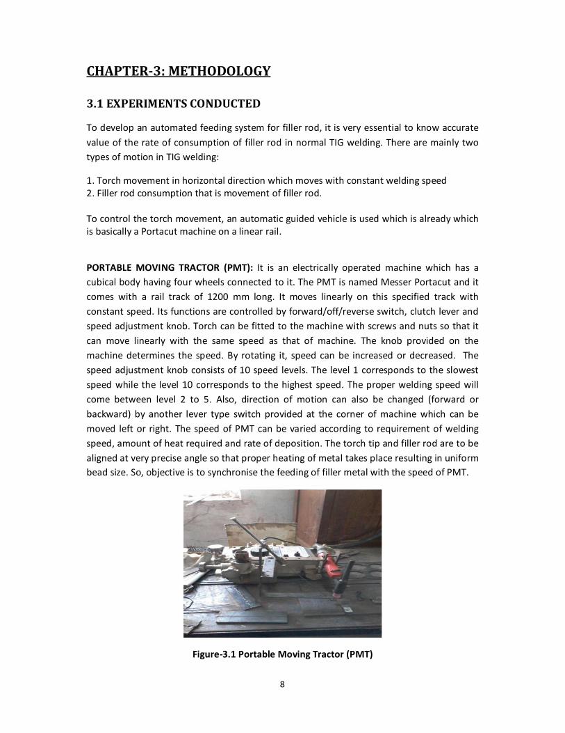
PORTABLE MOVING TRACTOR (PMT): It is an electrically operated machine which has a
cubical body having four wheels connected to it. The PMT is named Messer Portacut and it
comes with a rail track of 1200 mm long. It moves linearly on this specified track with
constant speed. Its functions are controlled by forward/off/reverse switch, clutch lever and
speed adjustment knob. Torch can be fitted to the machine with screws and nuts so that it
can move linearly with the same speed as that of machine. The knob provided on the
machine determines the speed. By rotating it, speed can be increased or decreased. The
speed adjustment knob consists of 10 speed levels. The level 1 corresponds to the slowest
speed while the level 10 corresponds to the highest speed. The proper welding speed will
come between level 2 to 5. Also, direction of motion can also be changed (forward or
backward) by another lever type switch provided at the corner of machine which can be
moved left or right. The speed of PMT can be varied according to requirement of welding
speed, amount of heat required and rate of deposition. The torch tip and filler rod are to be
aligned at very precise angle so that proper heating of metal takes place resulting in uniform
bead size. So, objective is to synchronise the feeding of filler metal with the speed of PMT.
Figure-3.1 Portable Moving Tractor (PMT)

9
• Speed calibration of PMT under no load condition
1) The PMT is switched ON and it is moved at speed dial 1.
2) Two points at a distance of 15cm is marked on the rail track.
3) As soon as the PMT crosses the first point, the stopwatch is started and stopped as the
PMT reaches the second point.
4) The process is repeated at rest of the speed dials.
Speed Calibration Table
Table-3.1
Speed dial/knob level Speed value(mm/s)
1 2.5
1.5 3
2 3.50
2.5 4.0
3 4.5
3.5 5
4 5.5
4.5 6
• Experiment for speed calibration of PMT during welding
1) The speed adjustment knob is placed at speed dial 3.
2) A 15cm mild steel plate is placed below the tip of the torch connected to the PMT.
3) The PMT is started. It is ensured that the TIG welding is powered OFF.
4) As an arc is produced between the electrode and the work piece, stopwatch is started.
5) The observation is noted as soon as the electrode tip leaves the plate.
Speed at dial 3 during welding:
Table-3.2
The speed of PMT at speed dial 3 was found to be around 4 mm/sec.; similar experiments
can be done to determine the speed of the speed dial during welding at other knob levels.
The PMT carries an extra weight of the welding torch and the feeding arrangement on a
single side. Hence, it is very likely that its speed will vary from that of no load condition.
LENGTH TIME SPEED
15cm 35 sec 4.3 mm/sec
15cm 38 sec 3.9 mm/sec

10
• Experiment to determine filler rod deposition/decomposition rate
An experiment was carried out to determine consumption rate of stainless steel and mild
steel filler rod. For this, a sample work piece is kept under a torch to perform welding.
Feeding of filler rod was done manually with hand. Initially, the main switch of PMT was
switched ON. The speed dial was kept at third position. The electrode tip was kept at a
suitable distance from work piece to cause continuous arc. When electrode tip crosses one
end of the workpiece then stopwatch was started and time was stopped when it crossed the
other end of the work piece. The experiment could also be conducted by stopping the
welding at the completion of a minute. Finally, the filler rod deposition/decomposition rate
was calculated:
Initial length of filler rod was measured accurately. After welding of 60 seconds, length was
again measured.
Initial length of filler rod= 45 cm
Final length of filler rod= 28.8 cm
Consumption rate= 45- 28.8= 16.2 cm per minute.
Voltage = 16.8 V
Current = 53 A
A similar experiment was carried out with mild steel filler rod just to check any variation in
values.
In that case, observations were:
Initial length of filler rod= 28 cm
Time of welding = 37 seconds = 0.616 min
Final length of filler rod= 16.5 cm
Rate of consumption = (28- 16.5)/ 0.616 = 18.64 cm per min.
Voltage = 17.5 V
Current = 52 A
So, if we take average of two final values obtained by two different types of filler rods, we
get, consumption rate= 17 cm per min. According to this value, further calculations were
done for various mechanisms suggested.
3.2 FEEDING MECHANISMS
To get over the disadvantages of wire-feed mechanisms, three mechanisms were suggested:
1. Slider-crank mechanism
2. Rack-pinion arrangement
3. Screw and nut mechanism.
A detailed description of the three mechanisms is as follows:
SLIDER-CRANK MECHANISM: In this mechanism, a slider which is operated by a rotating
crank is used to feed the filler rod by attaching the rod to the end of the slider. This slider
moves to-and-fro on a single track when crank is rotated with the help of a connecting rod

11
provide between the crank and the slider. This type of mechanism is mainly used in an
internal combustion engine in which piston reciprocates according to crankshaft.
The crank can be rotated by electric motor or by using man power. Since, we need to
automate this mechanism; the use of an electric motor is preferred. The motor will be
connected to the crank. Gears may be used to reduce the rpm of the motor though it is
preferred to use a low rpm motor. The speed of the motor may also be voltage controlled.
On half rotation of the crank, the slider and in turn the filler rod will make a complete linear
displacement. A filler rod can be attached to the end of a slider by some clamping
mechanism. A possible arrangement is shown in the figure.
The main difficulties are maintaining low speed of the crank and the lack of uniformity in its
motion. The filler rod should have a constant forward velocity compensating for its rate of
decomposition. But, the slider will never have constant velocity in its path. At the extreme
position of slider, it stops for some time known as ideal time. In this position, it has
maximum acceleration. At each point on its track, it has some acceleration. So, for a
constant feeding, this mechanism can never be applied. To make it work, motor speed
driving the crank should be continuously controlled to make slider move with constant
velocity, which is very difficult in practical sense.
Figure-3.2 Slider Crank Mechanism

12
RACK AND PINION ARRANGEMENT: A rack and pinion is a type of linear actuator that
comprises of a pair of gears which converts rotational motion into linear motion. A circular
gear called pinion engages or meshes its teeth with that of a linear gear. The rotational
motion of pinion by external motor causes rack to move with a constant velocity. A filler rod
can be attached at the end of rack for constant feeding. The velocity of rack should be equal
to the consumption rate of filler rod.
Velocity of rack= V = 18 cm/ min which is the closest value to the average rate calculated
before.
Also, we know, W*R= V
Where R= radius of the pitch circle of the pinion; W= angular velocity of the pinion.
Thus, R = V/W
Taking W= 2 rpm which is the lowest rpm that is generally available for any motor
W=2 rpm= (2*2 )/60 radians/sec.
And, V= 18 cm/min= 0.003 m/s.
Putting these values , we get, R= 0.003/( /15) = 14.33 mm. = 1.433 cm.
Assuming module of pinion= m= 1.25mm
T= number of teeth on pinion = D/m = (2*R)/m = (2*14.33)/1.25= 22 approximately.
These calculations are done taking into consideration the minimum rpm that can be possible
for motor. If we increase the motor speed, then R will decrease keeping the velocity of rack
constant. This pinion with decreased radius will be very difficult to manufacture with 22 or
more number of teeth. A lot of skill and hence cost will be required to make a single pinion.
Apart from this, a lot of drawbacks of this method can be possible that can be listed as
follows:
1. Components like rack and pinion of exact size and meshing are too costly to buy. It is
not affordable for our project.
2. For better and smooth performance of rack-pinion, they should be made up of
hardened materials like stainless steel, mild steel or cast iron. This will make the
whole assembly heavy and bulky.
3. While feeding, the rack may accelerate due to its own weight as rack will be in
inclined position. This acceleration due to gravity will prove to be a detrimental
factor for constant velocity feeding.

13
Figure-3.3 Rack and Pinion Mechanism
So, this method can be feasible but its limitations outweigh its advantages.
SCREW AND NUT MECHANISM: In this mechanism, linear feeding is provided by movement
of screw at the end of which filler rod is connected by clamping mechanism. The screw
passes through a nut which is fixed to the frame of PMT. The rotary motion of screw
required for its linear displacement is given by connecting it to an external electric motor.
The motor s output shaft will be connected firmly to the screw so that it rotates with the
same rpm as that of motor. With one revolution of the motor, screw passes by a distance
equal to the pitch of the screw. To make the motor move with the screw, a proper linear
guide has to be provided for motor. As the filler rod gets consumed, the motor will also
move linearly with the screw to compensate this consumption with the help of linear guide.
But, the displacement of the filler rod is restricted to the length of the screw. The guide,
motor and screw should be oriented in the proper direction so as to reach the torch tip at a
suitable angle.
There are many advantages to this method:
• Components required for working of this mechanism can be available anywhere and
also in the affordable rates.
• The linear motion of screw has the constant velocity all the time and it will not be
affected by gravity as the motion will always be restricted to the engagement with
the screw.
• There is always an upward normal force on the motor shaft along its axis exerted by
the screw. This force prevents sliding of the motor due to gravity.

14
Figure-3.4 Screw and Nut Mechanism
Figure-3.5 Screw and Nut Mechanism [Ref.: www.buildyourcnc.com]

15
CHAPTER-4 RESULTS AND DISCUSSION
Due to mentioned advantages of a screw-nut mechanism over other two suggested
mechanisms, it was finalised to be worked out for feeding of filler rod. For this, the list of
components required is as follows:
1. Bolt and nut: A long bolt of length approximately 30 cm and the corresponding nut
of the same threading are taken. The pitch of the screw varies from 0.8-1 mm. The
nut is to be fixed to the assembly with a proper alignment. The length of the bolt is
decided by the length of the filler rod. Moreover, the lower the pitch of the bolt,
higher the rpm of motor is required.
2. Motor: It consists of a 12V DC motor which has a separate AC-DC adapter provided.
This adapter has a knob on it which can be used to vary the input voltage of motor
from 0V-12V by rotating it. This controls the motor rpm. Motor moves linearly with a
distance equal to the pitch of the screw in one rotation.
As consumption rate is approximated to be at 18cm/min, motor should move 18 cm
distance in one minute. For this to happen, total number of revolutions required per
minute = (Consumption rate/ pitch of screw)
Assuming pitch be 0.8 mm= 0.08 cm, 18/0.08 = 225 revolutions per minute.
As the pitch varies from 0.8 -1 mm, the average rpm of the motor can be assumed to
be at 200 rpm.
3. Couplers: These are also known as universal couplers and are used to connect the
motor shaft to the screw. Their assembly with the electric motor is shown in figure
4.1. Each coupler has a central big hole and many small holes on its face. The two
couplers can be connected to each other by inserting bolts in all the holes. Through
the big hole of one coupler, motor shaft is inserted and through another hole, screw
is inserted. And then both the couplers were connected firmly to each other as
shown in figure 4.2.
Figure-4.1 Coupler

16
Figure-4.2 Motor coupled to the screw
4. SLIDER-RAIL:
As mentioned earlier, motor will require linear guide for feeding. For this, a slider-rail
was used. Linear guides are a set of components that are used to achieve precise
linear motion. They consist of a block that slides smoothly on a rectangular rail. For
this project, both slider and the rail are manufactured by using the rapid-prototyping
technology. It manufactures a physical model by using computer aided design (CAD)
data. Construction of the part is usually done with 3D printing additive layer
manufacturing technology. The reasons behind using this technology are:
1. It is impossible to buy the sliders from market due to its rare availability and
extremely high prices.
2. In RP, customization can be easily done and manufactured.
3. Model material used is Acrylonitrile Butadiene Styrene plastic which has
reasonably high strength, impact resistance and toughness which fulfils our
requirement.
4. Raw material used in RP doesn t get corroded or wears out easily. Hence, it has
very long service life.
The slider and the rail are fabricated simultaneously but as different parts in the
rapid prototyping machine. It needs to be ensured that the dimensions of slider and
rail lie within the range of the rapid prototyping machine bed. The procedure to
manufacture a slider-rail by rapid prototyping is as follows:
1) The Solid Works file of the model is generated with proper dimensioning.

17
2) It is saved as a STL file which is processed, meshing and orienting the model for
the build process. Support structures are generated.
3) The model or parts are produced by extruding small beads of thermoplastic
material to form layer.
4) The thermoplastic material is supplied to a nozzle by unwinding from a coil. The
rate of supply of material to the nozzle is controlled by a worm-drive
mechanism. The nozzle is heated.
5) The nozzle s movement is controlled by NC mechanism. The part is built from
the bottom up based on a CAM software package.
Figure-4.3 Slider rail
Figure-4.4 Projection views of slider rail
18
Specifications of slider rail-
1) Length=34cm
2) Effective sliding length=30cm
3) Two pockets of M5 bolt are done on each side of the rail at a distance of 1cm.
4) Material=Thermoplastic
5) Groove radius=5mm
6) Width=6cm
7) Edge thickness=1cm
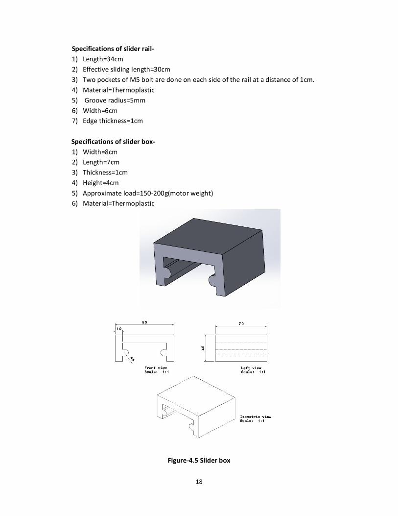
Specifications of slider box-
1) Width=8cm
2) Length=7cm
3) Thickness=1cm
4) Height=4cm
5) Approximate load=150-200g(motor weight)
6) Material=Thermoplastic
Figure-4.5 Slider box

19
5. Modified PMT- Portable Moving Tractor design was modified so that it can sustain
the load of whole assembly of mechanism. As shown in the figure 4.6, two supports
were separately welded to the main frame to give sufficient support to the slider rail
by inserting M5 bolts between them. Also, the nut through which the bolt passes is
separately welded taking into consideration the coincidence of nut to the torch tip
and the alignment of the bolt with the nut.
Figure-4.6 Modified PMT
6. Filler rod holder- The filler rod is fixed to the bolt with the help of a cylindrical clamp. A
piece of thick rod around 1.5 cm in diameter is cut to act as the filler rod holder. The
cylindrical clamp has internal threading identical to that of the bolt which aids in its
assembling and disassembling. Thus, one side of the clamp will be assembled to the main
bolt through a hole of diameter 1cm while the other side with a hole of about 3mm diameter
and 1cm long will be free for the filler rod to be fixed. To make best fitting of this filler rod,
the clamp is provided with two diametrically opposite holes through which two bolts can be
inserted that fit the filler rod in between them and keep it always at the centre of the hole.
The maximum diameter of the filler rod that can be clamped is approximately 3mm.
Figure-4.7 Filler rod holder
Screw is held
Here
Filler rod is
Inserted here
Bolt is inserted for
Tightening

20
FINAL ASSEMBLY
All the components including the motor, bolt, slider, filler rod holder and filler rod are
assembled with the PMT as shown in the figure 4.7 and 4.8.
Figure-4.8 Isometric view of the final assembly
Figure-4.9 Side view of the final assembly
DC Motor
Slider
Screw-nut mechanism
Slider box
Portable
Moving
Tractor
TIG
Nozzle
Holder

21
CHAPTER-5 CONCLUSIONS AND FUTURE SCOPE
Research on this topic is expected to open new doors in the field of filler rod feeding
mechanisms. Most of the present inventions are based on wire feeding mechanism. But, the
use of a filler rod instead of filler wire may bring some significant changes in industrial
welding practices. Moreover, the following invention is not limited to the feeding of filler
rod only. In fact, the screw and nut mechanism proposed here can be used to provide
motion to any kind of rod. In many cases, such as high pressure injection welding, rolling
and in many other primary and secondary manufacturing processes, feeding of some kind of
raw material is required. The mechanism discussed here can cater to this requirement by
providing an automated arrangement for the same. But, much work needs to be done in this
area before these types of arrangements can be inducted in industries.
The following feeding mechanism can also find its use in TIG cladding. Cladding is an
effective process against corrosion and wear. In the process, a layer of weld metal is clad on
the base metal. The material characteristics and properties of this weld metal are generally
different than the base metal. This weld metal can be fed to the work piece by using the
screw and nut mechanism proposed here. The Though, the following apparatus is not
exclusively designed for its use in an arrangement for filler rod feeding in TIG welding, at
present, the discussion shall be restricted to its use and future scope in TIG and related
welding processes only.
With the demand of labour increasing and companies trying to increase the rate of their
mass production, the automated filler rod feeding system will surely find its way for use in
industries. Currently, the available feeding system is mostly wire based restricting its
deposition rate, as wires have smaller diameter compared to rods. Moreover, most of these
filler wires are specially manufactured or compatible to a particular type of wire feeding
system which restricts its use to a large extent. But, the automated filler rod feeding system
discussed here is more versatile as it can be used for almost all types of filler rods with slight
modifications in the apparatus. This type of arrangement helps when the deposition rate
varies or when different materials are needed to be welded with their corresponding filler
materials.
The present arrangement consists of a Portable Moving Tractor which provides forward and
backward motion to the whole assembly. But, the distance it can cover is limited as it is
dependent on the length of rail. Moreover, it can only provide linear motion, making it
difficult to weld curved plates. The angle between the filler rod and the torch is also almost
constant. Depending on the welding voltage, one may need to change the angle between
the electrode tip and the filler rod. These are some of the open problems that need to be
solved with further improvements in design.

22
A possible arrangement can be designing a table or base for the work piece whose position
can be controlled in the three major axes. The table may also provide the flexibility to the
operator to weld the work piece at an angle. One may also find the apparatus used here as
bulky. With proper design considerations, its size can be reduced. The screw and nut
mechanism used here for the automation of the filler rod in TIG welding is only one of the
many mechanisms possible and may not prove to be the best also. If proper attention is
given to this field and enough research is done in this area, new and more viable
mechanisms will come into light.

23
BIBLIOGRAPHY
[1] Honma S & Yasuda K, Study of Semi-automatic TIG welding , Welding International,
18:6, 450-455, 2004
[2] Hussain Ahmed Khalid, Lateef Abdul, Javed Mohd., Pramesh.T, Influence of welding
speed on tensile strength of welding joint in TIG welding process , International Journal of
Applied Engineering Research, Dindigul, Vol. 1, No 3, 2010
[3] Clarence H. Drader, Forwarding a rod for use in welding by high pressure injection , US
6302309 B1 ,2001
[4] Nagai Shigekazu, Someya Masahiko, Shiomi Hiroyuki, Guide mechanism , US5711611 A,
1998
[5] Lngley Thomas Guinn, Manual welding wire feeder , US5782394 A, 1998
[6] Christopher Mark, Maynard Jim, Piechowski Jerry, Wire feed control assembly ,
US7465902 B2, 2008
[7] Rao P.N., Manufacturing Processes Vol. 1 third edition , Tata Mcgraw Hill Education
Private Limited, Third Edition
[8] Achtner Mark Richard, Albrecht Patrick Bruce, Jr. Lauer H. Leroy, TIG Welding system and
method, US 8026456 B2, 2011
[9] Karunakaran N., Effect of Pulsed Current on Temperature Distribution, Weld Bead
Profiles and Characteristics of GTA Welded Stainless Steel Joints, International Journal of
Engineering and Technology, Vol. 2, No. 12, 2012
[10] Narang H.K., Mahapatra M.M., Jha P.K., Prediction of the weld pool geometry of TIG
arc welding using fuzzy logic controller, International Journal of Engineering, Science and
Technology, Vol. 3, No. 9, 2011


