Daikin McQuay Pathfinder™ Air Cooled Chiller
Screw Compressor2 Circuit
Model: AWSSizes: 280- 350
Vintage: AR134a50 Hz
Replacement Parts List No. 700014200New 08/09
To find your McQuay parts distributor, call 1-800-377-2787 or visit www .mcquay. com

Air Cooled Screw Comp. Chiller, AWS 280-350 50Hz Vint. A New 08/09 RPL 700014100 / Page 2
ContentsParts List Revision History .................................................................................................................................. 3Nomenclature Serial Number ............................................................................................................................................... 4 Unit Model Number- Dataplate ..................................................................................................................... 4 Unit Model Number- Complete ................................................................................................................. 5, 6Electrical Legend ..........................................................................................................................................7- 10Unit Layout........................................................................................................................................................ 11Refrigeration Section Pressure Switches, Transducers, Comp. Solenoid Valves, Relief Valves, Compressor Mounting............... 12 Compressors & Heaters- Standard Efficiency Units (Code 04= SE) .......................................................... 13 Compressors & Heaters- High Efficiency Units (Code 04= HE) ................................................................. 14 Suction Lines, Discharge Lines, Liquid Injection Lines ......................................................................... 15, 16 Liquid Lines- Standard Efficiency Units (Code 04= SE)- Sizes 300ADS, 320ADWS, 350ADS .................. 17 Liquid Lines with Economizer- High Eff. Units (Code 04= HE)- Sizes 300ADH, 320ADH, 350ADH ..... 18, 19 Liquid Lines with Economizer- High Eff. Units (Code 04= HE)- Sizes 380ADH, 405ADH .................... 20, 21 Condenser Coils and Fans ......................................................................................................................... 22 Evaporator and Components ...................................................................................................................... 23 Base Frame Grilles- Code 28= F, C ............................................................................................................ 24 Base Frame Louvers- Code 28= B ............................................................................................................. 25 Coil Grilles- Code 28= G, F ........................................................................................................................ 26 Coil Louvers- Code 28= L, B, C .................................................................................................................. 26Controls Box Locations and Label Detail .................................................................................................................. 27 Control Panel Detail .................................................................................................................................... 28 Power Panel- Left Side Detail ..................................................................................................................... 29 Power Panel- Right Side Detail ............................................................................................................. 30, 31 Solid State Starter Panel- Circuit 1- Code 09= SS ..................................................................................... 32 Solid State Starter Panel- Circuit 2- Code 09= SS ..................................................................................... 33 Wye-Delta Starter Panel- Circuit 1- Code 09= WD ..................................................................................... 34 Wye-Delta Starter Panel- Circuit 2- Code 09= WD ..................................................................................... 35 Terminal Box ............................................................................................................................................... 36Accessories Isolators— Rubber-In-Shear- Aluminum Fin Coils (Code 08= A, B, E) ...................................................... 37 Isolators— Rubber-In-Shear- Copper Fin Coils (Code 08= C, F) ............................................................... 37 Isolators— Springs - Aluminum Fin Coils (Code 08= A, B, E) .................................................................... 37 Isolators— Springs - Copper Fin Coils (Code 08= C, F) ............................................................................. 37 Flow Switches ............................................................................................................................................. 38 Sound Enclosure Kit ................................................................................................................................... 38 Base Grilles ................................................................................................................................................ 38 Coil Louvers ................................................................................................................................................ 38 Base and Coil Louvers ................................................................................................................................ 38 BACnet with IP/Ethernet ............................................................................................................................. 39 BACnet Communications Module MS/TP ................................................................................................... 39 MODBUS Communications Module ........................................................................................................... 39 LonMark Communications Module ............................................................................................................. 39 Remote Display Kit ..................................................................................................................................... 39

Air Cooled Screw Comp. Chiller, AWS 280-350 50Hz Vint. A New 08/09 RPL 700014100 / Page 3
Revision Date Description NEW 08/09 New
Parts List Revision History
13600 Industrial Park Blvd., P.O. Box 1551, Minneapolis, MN 55440 (763) 553-5330
Air Cooled Screw Comp. Chiller, AWS 280-350 50Hz Vint. A New 08/09 RPL 700014100 / Page 4
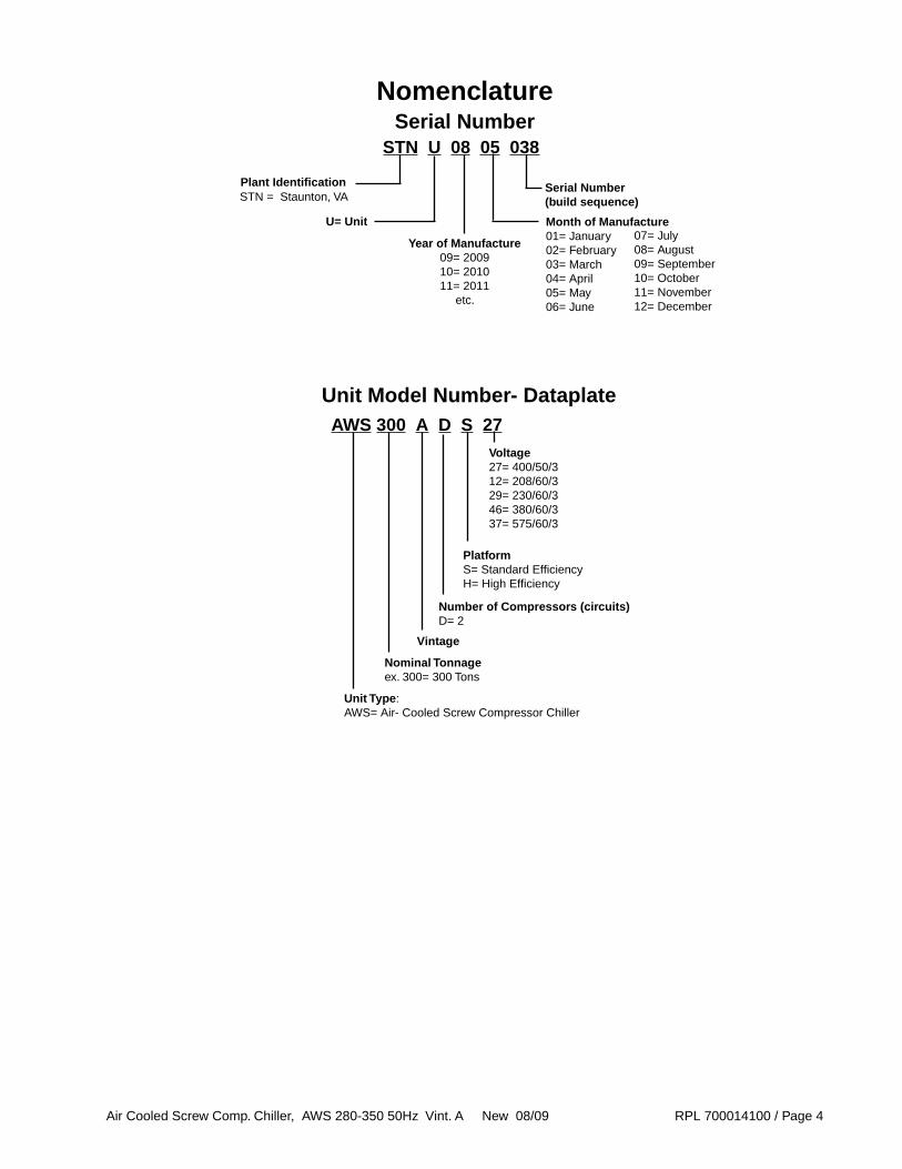
Nomenclature
AWS 300 A D S 27
Unit Model Number- Dataplate
Unit Type: AWS= Air- Cooled Screw Compressor Chiller
Nominal Tonnageex. 300= 300 Tons
Vintage
Number of Compressors (circuits)D= 2
STN U 08 05 038
Plant IdentificationSTN = Staunton, VA
Year of Manufacture09= 200910= 201011= 2011
etc.
U= Unit
Serial Number (build sequence)
Month of Manufacture01= January02= February03= March04= April05= May06= June
07= July08= August09= September10= October11= November12= December
Serial Number
PlatformS= Standard Efficiency H= High Efficiency
Voltage27= 400/50/312= 208/60/329= 230/60/346= 380/60/337= 575/60/3
Air Cooled Screw Comp. Chiller, AWS 280-350 50Hz Vint. A New 08/09 RPL 700014100 / Page 5
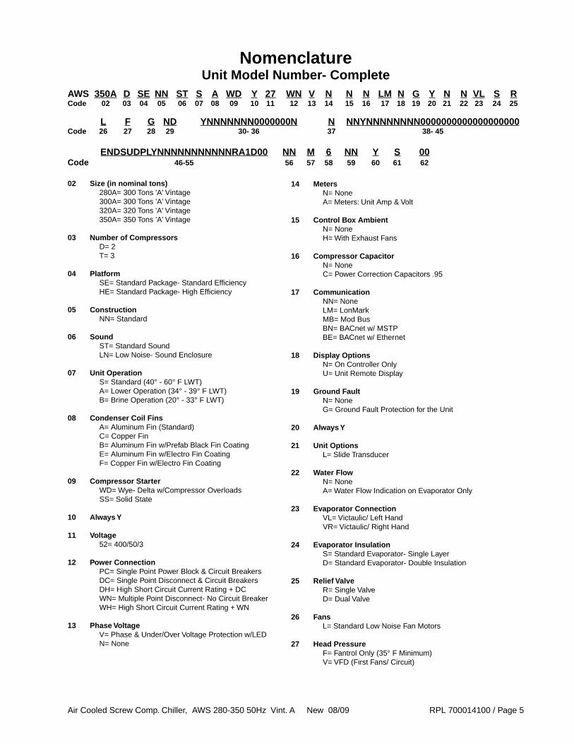
AWS 350A D SE NN ST S A WD Y 27 WN V N N N LM N G Y N N VL S RCode 02 03 04 05 06 07 08 09 10 11 12 13 14 15 16 17 18 19 20 21 22 23 24 25
L F G ND YNNNNNNN0000000N N NNYNNNNNNNN0000000000000000000Code 26 27 28 29 30- 36 37 38- 45
02 Size (in nominal tons) 280A= 300 Tons 'A' Vintage 300A= 300 Tons 'A' Vintage 320A= 320 Tons 'A' Vintage 350A= 350 Tons 'A' Vintage
03 Number of Compressors D= 2 T= 3
04 Platform SE= Standard Package- Standard Efficiency HE= Standard Package- High Efficiency
05 Construction NN= Standard
06 Sound ST= Standard Sound LN= Low Noise- Sound Enclosure
07 Unit Operation S= Standard (40° - 60° F LWT) A= Lower Operation (34° - 39° F LWT) B= Brine Operation (20° - 33° F LWT)
08 Condenser Coil Fins A= Aluminum Fin (Standard) C= Copper Fin B= Aluminum Fin w/Prefab Black Fin Coating E= Aluminum Fin w/Electro Fin Coating F= Copper Fin w/Electro Fin Coating
09 Compressor Starter WD= Wye- Delta w/Compressor Overloads SS= Solid State
10 Always Y
11 Voltage 52= 400/50/3
12 Power Connection PC= Single Point Power Block & Circuit Breakers DC= Single Point Disconnect & Circuit Breakers DH= High Short Circuit Current Rating + DC WN= Multiple Point Disconnect- No Circuit Breaker WH= High Short Circuit Current Rating + WN
13 Phase Voltage V= Phase & Under/Over Voltage Protection w/LED N= None
NomenclatureUnit Model Number- Complete
ENDSUDPLYNNNNNNNNNNNRA1D00 NN M 6 NN Y S 00Code 46-55 56 57 58 59 60 61 62
14 Meters N= None A= Meters: Unit Amp & Volt
15 Control Box Ambient N= None H= With Exhaust Fans
16 Compressor Capacitor N= None C= Power Correction Capacitors .95
17 Communication NN= None LM= LonMark MB= Mod Bus BN= BACnet w/ MSTP BE= BACnet w/ Ethernet
18 Display Options N= On Controller Only U= Unit Remote Display
19 Ground Fault N= None G= Ground Fault Protection for the Unit
20 Always Y
21 Unit Options L= Slide Transducer
22 Water Flow N= None A= Water Flow Indication on Evaporator Only
23 Evaporator Connection VL= Victaulic/ Left Hand VR= Victaulic/ Right Hand
24 Evaporator Insulation S= Standard Evaporator- Single Layer D= Standard Evaporator- Double Insulation
25 Relief Valve R= Single Valve D= Dual Valve
26 Fans L= Standard Low Noise Fan Motors
27 Head Pressure F= Fantrol Only (35° F Minimum) V= VFD (First Fans/ Circuit)

Air Cooled Screw Comp. Chiller, AWS 280-350 50Hz Vint. A New 08/09 RPL 700014100 / Page 6
28 Guards G= Condenser Coil Grilles Only F= Condenser Coil & Base Frame Grilles L= Condenser Coil Louvers B= Condenser Coil Louvers & Base Guard Louvers C= Condenser Coil Louvers and Base Frame Grilles
29 Tubing Options ND= With Discharge Shut-Off Valve SD= With Suction and Discharge Shut-Off Valve LD= ND + Liquid Line Solenoid SL= DS + Liquid Line Solenoid
30 Always Y
31 Water Pump NN= None
32 Pump Type NNNN= No Pump Package
33 Pump Connection N= No Pump Package
34 Pump Flow Always 0000
35 Total Head Always 000
36 Pump Starter N= No Pump Package
37 Pump Gauges N= None
38 Pump Suction Valve N= None
39 Pump Discharge Valve N= None
40 Always Y
41 Impeller Trim NNNN= No Pumps
42 Expansion Tank NN= None
43 Buffer Tank NN= None
44 % of Glycol 000= None
45 Pump Number All 0's= None
NomenclatureUnit Model Number- Complete, Continued
46 Approvals N= No agency label
47 CRN- Evaporator N= None
48 Unit Start ISU= International- No Start Up Provided
49 Standard Warranty TPN= International 1st Year Standard Warranty
50 Always Y
51 Extended Compressor Warranty NNNN= No Extended Compressor Warranty CPE*= Compressor Only- Parts Only (*= no. of years) CBE*= Compressor Only- Parts & Labor (*= no. of years)
52 Always NNN
53 Extended Unit Warranty NNNN= None EPE*= Ext. Unit- Parts Only (*= no. of years) EBE*= Ext. Unit- Parts & Labor (*= no. of years)
54 Refrigerant Warranty NNN= None
55 Delayed Warranty Start D00= 0 months
56 Always NN
57 Brand Name D= DaikenMcQuay M= McQuay
58 Hertz 5= 50 Hertz
59 & 60 Always YY
61 Misc. S= Standard Unit X= Special
62 Major Unit Change Revision 00= No Revision
Air Cooled Screw Comp. Chiller, AWS 280-350 50Hz Vint. A New 08/09 RPL 700014100 / Page 7
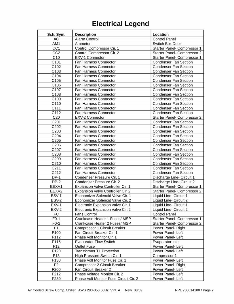
Electrical Legend Sch. Sym. Description Location AC Alarm Control Control Panel AM1 Ammeter Switch Box Door CC1 Control Compressor Cir. 1 Starter Panel- Compressor 1 CC2 Control Compressor Cir. 2 Starter Panel- Compressor 2 C10 EXV-1 Connector Starter Panel- Compressor 1 C101 Fan Harness Connector Condenser Fan Section C102 Fan Harness Connector Condenser Fan Section C103 Fan Harness Connector Condenser Fan Section C104 Fan Harness Connector Condenser Fan Section C105 Fan Harness Connector Condenser Fan Section C106 Fan Harness Connector Condenser Fan Section C107 Fan Harness Connector Condenser Fan Section C108 Fan Harness Connector Condenser Fan Section C109 Fan Harness Connector Condenser Fan Section C110 Fan Harness Connector Condenser Fan Section C111 Fan Harness Connector Condenser Fan Section C112 Fan Harness Connector Condenser Fan Section C20 EXV-2 Connector Starter Panel- Compressor 2 C201 Fan Harness Connector Condenser Fan Section C202 Fan Harness Connector Condenser Fan Section C203 Fan Harness Connector Condenser Fan Section C204 Fan Harness Connector Condenser Fan Section C205 Fan Harness Connector Condenser Fan Section C206 Fan Harness Connector Condenser Fan Section C207 Fan Harness Connector Condenser Fan Section C208 Fan Harness Connector Condenser Fan Section C209 Fan Harness Connector Condenser Fan Section C210 Fan Harness Connector Condenser Fan Section C211 Fan Harness Connector Condenser Fan Section C212 Fan Harness Connector Condenser Fan Section DP-1 Condenser Pressure Cir. 1 Discharge Line- Circuit 1 DP-2 Condenser Pressure Cir. 2 Discharge Line- Circuit 2 EEXV1 Expansion Valve Controller Cir. 1 Starter Panel- Compressor 1 EEXV2 Expansion Valve Controller Cir. 2 Starter Panel- Compressor 2 ESV-1 Economizer Solenoid Valve Cir. 1 Liquid Line- Circuit 1 ESV-2 Economizer Solenoid Valve Cir. 2 Liquid Line- Circuit 2 EXV-1 Electronic Expansion Valve Cir. 1 Liquid Line- Circuit 1 EXV-2 Electronic Expansion Valve Cir. 2 Liquid Line- Circuit 2 FC Fans Control Control Panel F0-1 Crankcase Heater 1 Fuses/ MSP Starter Panel- Compressor 1 F0-2 Crankcase Heater 2 Fuses/ MSP Starter Panel- Compressor 2 F1 Compressor 1 Circuit Breaker Power Panel- Right F100 Fan Circuit Breaker Cir. 1 Power Panel- Left F112 Phase Volt Monitor Cir. 1 Power Panel- Left F116 Evaporator Flow Switch Evaporator Inlet F12 Outlet Fuse Power Panel- Left F120 Transformer T1 Protection Power Panel- Left F13 High Pressure Switch Cir. 1 Compressor 1 F130 Phase Volt Monitor Fuse Cir. 1 Power Panel- Left F2 Compressor 2 Circuit Breaker Power Panel- Right F200 Fan Circuit Breaker 2 Power Panel- Left F212 Phase Voltage Monitor Cir. 2 Power Panel- Left F230 Phase Volt Monitor Fuse Circuit Cir. 2 Power Panel- Left

Air Cooled Screw Comp. Chiller, AWS 280-350 50Hz Vint. A New 08/09 RPL 700014100 / Page 8
Sch. Sym. Description Location F23 High Pressure Switch Circuit Cir. 2 Compressor 2 F5-1 Thermal Relay Starter Panel- Compressor 1 F5-2 Thermal Relay Starter Panel- Compressor 2 F59 Evaporator Heater Fuse Control Panel F90 Thermostat Control Panel FTB107 Fan Terminal Block Cir. 1 Power Panel- Left FTB110 Fan Terminal Block Cir. 1 Power Panel- Left FTB207 Fan Terminal Block Cir. 2 Power Panel- Left FTB210 Fan Terminal Block Cir. 2 Power Panel- Left GFR1 Ground Fault Relay Cir. 1 Power Panel- Left GFR2 Ground Fault Relay Cir. 2 Power Panel- Left K11 Emergency Stop Contactor Control Panel K16 Fan Stage Cir. 1 Power Panel- Left K26 Fan Stage Cir. 2 Power Panel- Left K2B-1 Contactor Starter Panel- Compressor 1 K2B-2 Contactor Starter Panel- Compressor 2 KM10 Power Factor Correction Contactor Cir. 1 Starter Panel- Compressor 1 KM101 Fan Motor Contactor Power Panel- Left KM10-1 Contactor Starter Panel- Compressor 1 KM102 Fan Motor Contactor Power Panel- Left KM10-2 Contactor Starter Panel- Compressor 2 KM105 Fan Motor Contactor Power Panel- Left KM107 Fan Motor Contactor Power Panel- Left KM1-1 Compressor Contactor Starter Panel- Compressor 1 KM110 Fan Motor Contactor Power Panel- Left KM1-2 Compressor Contactor Starter Panel- Compressor 2 KM20 Power Factor Correction Contactor Cir. 2 Starter Panel- Compressor 2 KM201 Fan Motor Contactor Power Panel- Left KM202 Fan Motor Contactor Power Panel- Left KM203 Fan Motor Contactorq Power Panel- Left KM205 Fan Motor Contactor Power Panel- Left KM207 Fan Motor Contactor Power Panel- Left KM2-1 Compressor Contactor Starter Panel- Compressor 2 KM2-2 Compressor Contactor Starter Panel- Compressor 2 KM2-3 Compressor Contactor Starter Panel- Compressor 2 KT-1 Auxilliary Relay Cir. 1 Starter Panel- Compressor 1 KT1-1 Delay Relay Starter Panel- Compressor 1 KT1-2 Delay Relay Starter Panel- Compressor 2 KT-2 Aux. Relay Cir. 2 Starter Panel- Compressor 2 LJV-1 Liquid Injection Solenoid/Relay Cir. 1 Liquid Line/Starter Panel 1 LJV-2 Liquid Injection Solenoid/Relay Cir. 2 Liquid Line/Starter Panel 2 LR1 Line Reactor Cir. 1 Power Panel- Left LR2 Line Reactor Cir. 2 Power Panel- Left LSV-1 Liquid Line Solenoid Cir. 1 Liquid Line- Circuit 1 LSV-2 Liquid Line Solenoid Cir. 2 Liquid Line- Circuit 2 M1 Compressor Cir. 1 Base M10 Forced Ventilation Switch Box End M101 Fan Motor Power Panel- Left M102 Fan Motor Power Panel- Left M103 Fan Motor Power Panel- Left M104 Fan Motor Power Panel- Left M105 Fan Motor Power Panel- Left M106 Fan Motor Power Panel- Left
Electrical Legend, Continued

Air Cooled Screw Comp. Chiller, AWS 280-350 50Hz Vint. A New 08/09 RPL 700014100 / Page 9
Sch. Sym. Description Location M107 Fan Motor Power Panel- Left M108 Fan Motor Power Panel- Left M109 Fan Motor Power Panel- Left M110 Fan Motor Power Panel- Left M111 Fan Motor Power Panel- Left M112 Fan Motor Power Panel- Left M2 Compressor Cir. 2 Base M201 Fan Motor Power Panel- Left M202 Fan Motor Power Panel- Left M203 Fan Motor Power Panel- Left M204 Fan Motor Power Panel- Left M205 Fan Motor Power Panel- Left M206 Fan Motor Power Panel- Left M207 Fan Motor Power Panel- Left M207 Fan Motor Power Panel- Left M208 Fan Motor Power Panel- Left M209 Fan Motor Power Panel- Left M210 Fan Motor Power Panel- Left M211 Fan Motor Power Panel- Left M212 Fan Motor Power Panel- Left MP1 Motor Thermal Protection Starter Panel- Compressor 1 MP2 Motor Thermal Protection Starter Panel- Compressor 2 MPR1 Motor Protection Relay Cir. 1 Starter Panel- Compressor 1 MPR2 Motor Protection Relay Cir. 2 Starter Panel- Compressor 2 OP-1 Oil Pressure Cir. Cir. 1 Compressor 1 OP-2 Oil Pressure Cir. Cir. 2 Compressor 2 Q0 Unit ON - OFF Switch Control Panel Q1 Pump Down Switch Cir. 1 Control Panel Q10 Main Power Block or Disconnect Switch 1 Power Panel- Right Q20 Main Power Block or Disconnect Switch 2 Power Panel- Right Q101 Fan MSP Power Panel- Left Q102 Fan MSP Power Panel- Left Q103 Fan MSP Power Panel- Left Q105 Fan MSP Power Panel- Left Q107 Fan MSP Power Panel- Left Q11 Emergency Stop Switch Control Box Door Q110 Fan MSP Power Panel- Left Q12 Automatic Circuit Breaker Control Panel Q2 Pump Down Switch Cir. 2 Control Panel Q201 Fan MSP Power Panel- Left Q202 Fan MSP Power Panel- Left Q203 Fan MSP Power Panel- Left Q203 Fan MSP Power Panel- Left Q205 Fan MSP Power Panel- Left Q205 Fan MSP Power Panel- Left Q207 Fan MSP Power Panel- Left Q210 Fan MSP Power Panel- Left R1 Compressor Crankcase Heater Cir. 1 Compressor 1 R2 Compressor Crankcase Heater Cir. 2 Compressor 2 R5 Evaporator Heater Evaporator Shell SL-1 Slide Indicator Cir. 1 Compressor 1 SL-2 Slide Indicator Cir. 2 Compressor 2
Electrical Legend, Continued
Air Cooled Screw Comp. Chiller, AWS 280-350 50Hz Vint. A New 08/09 RPL 700014100 / Page 10
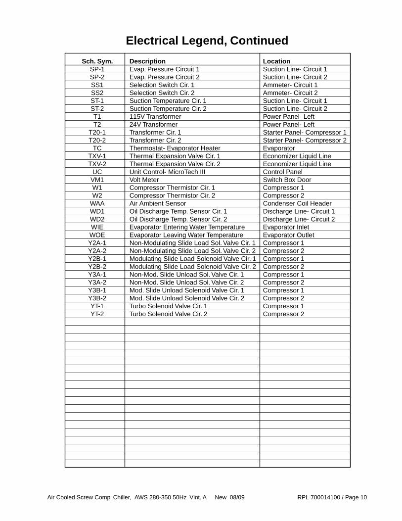
Sch. Sym. Description Location SP-1 Evap. Pressure Circuit 1 Suction Line- Circuit 1 SP-2 Evap. Pressure Circuit 2 Suction Line- Circuit 2 SS1 Selection Switch Cir. 1 Ammeter- Circuit 1 SS2 Selection Switch Cir. 2 Ammeter- Circuit 2 ST-1 Suction Temperature Cir. 1 Suction Line- Circuit 1 ST-2 Suction Temperature Cir. 2 Suction Line- Circuit 2 T1 115V Transformer Power Panel- Left T2 24V Transformer Power Panel- Left T20-1 Transformer Cir. 1 Starter Panel- Compressor 1 T20-2 Transformer Cir. 2 Starter Panel- Compressor 2 TC Thermostat- Evaporator Heater Evaporator TXV-1 Thermal Expansion Valve Cir. 1 Economizer Liquid Line TXV-2 Thermal Expansion Valve Cir. 2 Economizer Liquid Line UC Unit Control- MicroTech III Control Panel VM1 Volt Meter Switch Box Door W1 Compressor Thermistor Cir. 1 Compressor 1 W2 Compressor Thermistor Cir. 2 Compressor 2 WAA Air Ambient Sensor Condenser Coil Header WD1 Oil Discharge Temp. Sensor Cir. 1 Discharge Line- Circuit 1 WD2 Oil Discharge Temp. Sensor Cir. 2 Discharge Line- Circuit 2 WIE Evaporator Entering Water Temperature Evaporator Inlet WOE Evaporator Leaving Water Temperature Evaporator Outlet Y2A-1 Non-Modulating Slide Load Sol. Valve Cir. 1 Compressor 1 Y2A-2 Non-Modulating Slide Load Sol. Valve Cir. 2 Compressor 2 Y2B-1 Modulating Slide Load Solenoid Valve Cir. 1 Compressor 1 Y2B-2 Modulating Slide Load Solenoid Valve Cir. 2 Compressor 2 Y3A-1 Non-Mod. Slide Unload Sol. Valve Cir. 1 Compressor 1 Y3A-2 Non-Mod. Slide Unload Sol. Valve Cir. 2 Compressor 2 Y3B-1 Mod. Slide Unload Solenoid Valve Cir. 1 Compressor 1 Y3B-2 Mod. Slide Unload Solenoid Valve Cir. 2 Compressor 2 YT-1 Turbo Solenoid Valve Cir. 1 Compressor 1 YT-2 Turbo Solenoid Valve Cir. 2 Compressor 2
Electrical Legend, Continued

Air Cooled Screw Comp. Chiller, AWS 280-350 50Hz Vint. A New 08/09 RPL 700014100 / Page 11
Unit Layout(Unit Size 300ADS Shown)
10
1
8
2
Ref. No. Description Location 1 Compressors Refrigeration Section 2 Tubing (suction, discharge, liquid injection) Refrigeration Section 3 Liquid Line and Economizer Refrigeration Section 7 Evaporator Refrigeration Section 8 Condenser Coil Refrigeration Section 9 Condenser Fans Refrigeration Section 10 Unit Switch Box/Control Panel Controls Section 11 Compressor Starter Panel Controls Section 12 Compressor Terminal Box Controls Section
9
7
9 9 9 99 9 9
113
12

Air Cooled Screw Comp. Chiller, AWS 280-350 50Hz Vint. A New 08/09 RPL 700014100 / Page 12
Refrigeration SectionCompressors, Heaters, Pressure Switches, Transducers,
Solenoid Valves, Relief Valves, Compressor Mounting
Circuit # 1
10
11
213
14
52
1
Circuit # 250
5351
13A
54
1515A
15B
10
11
20013
14
52
100
50
5351
13A
54
15
15A15B
Ref Sch. Part Part No. Sym. Description Number Qty. 1 Compressor- Circuit #1 see next page 2 R1 Heater- Compressor see next page 2A Well- Heater 300043894 2 2B Bushing- Heater 132010016 2 10 F13, 23 Switch- High Pressure Control 290 PSI 073074009 2 11 OP1, 2 Transducer- Oil Pressure 0 to 30 bar 1000109562 2 13 Valve- Relief 325 PSI 735045859 2 13A Elbow- Relief Valve 1" 10000108772 2 14 SL1, 2 Transducer- Slide Indicator C21= L, B 10000108766 2 15 Valve- Shut Off 4.12 735039813 2 15A Screw- Hex 330821925 8 15B Washer- Lock 048164816 8 50 Isolator- Compressor 10000107046 4 51 Screw- Compressor Mount 330821905 24 52 Washer, Plain- Compressor Mount 040500310 32 53 Washer, Lock- Compressor Mount 048164814 24 54 Nut- Compressor Mount 330721904 16 60 Y2*1-1, 2 Valve, Solenoid- Load 1 4 60A Y3*1-1, 2 Valve, Solenoid- Unload 1 4 60B YT-1, 2 Valve, Solenoid- Turbo 1 2 100 Compressor- Circuit #2 see next page 200 R2 Heater- Compressor see next page
60A
60
60
60A
60
60
60B
60B
60A
60A
Y3B1
YT1
Y2B1
Y3A1
Y2A1
Y3B2
YT2
Y2B2
Y3A2
Y2A2
1 All solenoids are comprised of 4 components: Valve Body p/n 072932001; Valve Coil p/n 131066074; Valve Support Adapter p/n 332637801; Valve Support Gasket p/n 332130201.
R1F13
SL1
R2
F23
SL2
2A 2B
2A 2B
Air Cooled Screw Comp. Chiller, AWS 280-350 50Hz Vint. A New 08/09 RPL 700014100 / Page 13
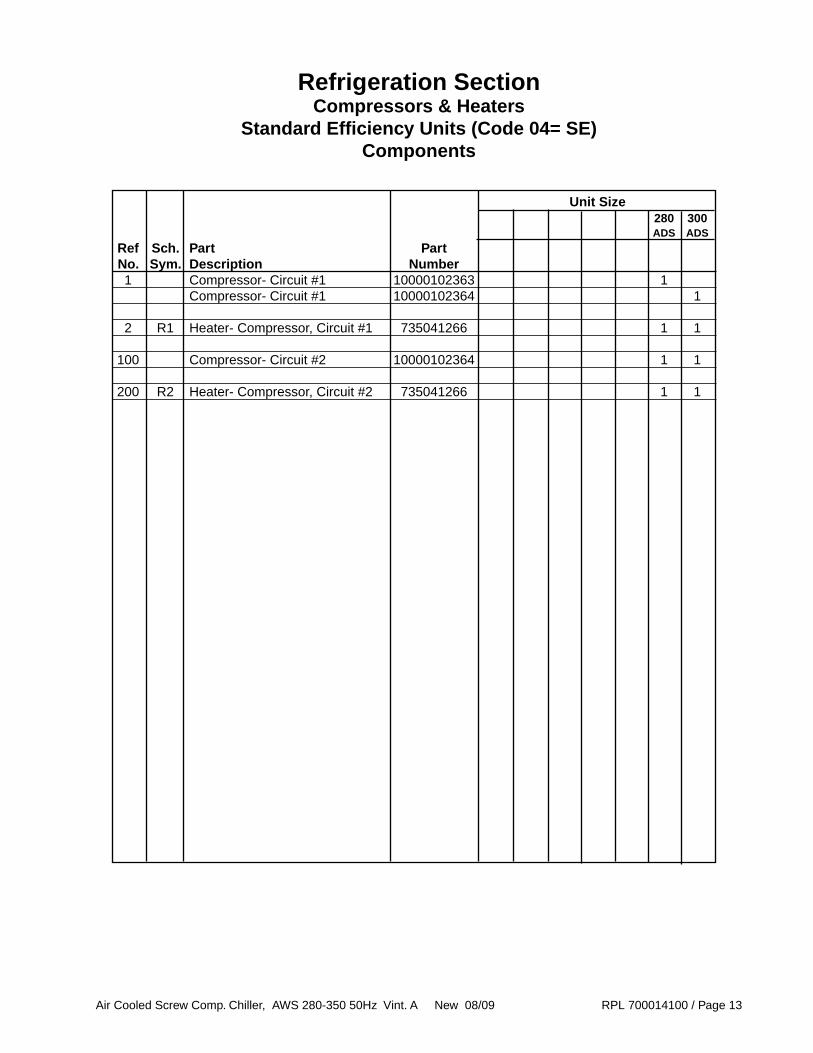
Refrigeration SectionCompressors & Heaters
Standard Efficiency Units (Code 04= SE)Components
Unit Size 280 300 ADS ADS
Ref Sch. Part Part No. Sym. Description Number 1 Compressor- Circuit #1 10000102363 1 Compressor- Circuit #1 10000102364 1
2 R1 Heater- Compressor, Circuit #1 735041266 1 1
100 Compressor- Circuit #2 10000102364 1 1
200 R2 Heater- Compressor, Circuit #2 735041266 1 1

Air Cooled Screw Comp. Chiller, AWS 280-350 50Hz Vint. A New 08/09 RPL 700014100 / Page 14
Refrigeration SectionCompressors & Heaters
High Efficiency Units (Code 04= HE)Components
Unit Size 300 320 350 ADH ADH ADH
Ref Sch. Part Part No. Sym. Description Number 1 Compressor- Circuit #1 10000102363 1 1 Compressor- Circuit #1 10000102364 1
2 R1 Heater- Compressor, Circuit #1 735041266 1 1 1
100 Compressor- Circuit #2 10000102363 1 Compressor- Circuit #1 10000102364 1 1
200 R2 Heater- Compressor, Circuit #2 735041266 1 1 1
Air Cooled Screw Comp. Chiller, AWS 280-350 50Hz Vint. A New 08/09 RPL 700014100 / Page 15
Liquid Injection DetailCircuit #1
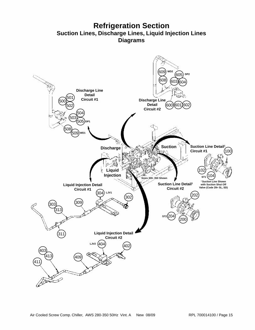
Refrigeration SectionSuction Lines, Discharge Lines, Liquid Injection Lines
Diagrams
Suction Line Detail1
Circuit #1
Suction Line Detail1
Circuit #2
202
200
102
311
100
313
309
304302
303
411413 409
404 402403
Liquid Injection DetailCircuit #2
Discharge Line Detail
Circuit #1
508
500501
502Discharge Line
DetailCircuit #2
608605
604603
600 601 602
505
504503
1 Suction Line Shown with Suction Shut Off
Valve (Code 29= SL, SD)
Sizes 300- 350 Shown
Suction
LiquidInjection
Discharge
509
609
204
104
DP2
DP1
LJV2
LJV1
WD2
WD1
ST1
ST2
Air Cooled Screw Comp. Chiller, AWS 280-350 50Hz Vint. A New 08/09 RPL 700014100 / Page 16
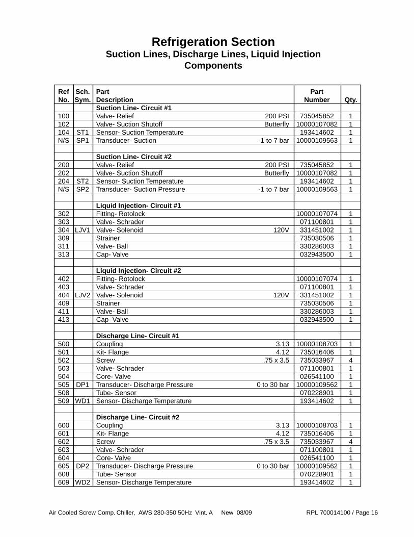
Refrigeration SectionSuction Lines, Discharge Lines, Liquid Injection
Components
Ref Sch. Part Part No. Sym. Description Number Qty. Suction Line- Circuit #1 100 Valve- Relief 200 PSI 735045852 1 102 Valve- Suction Shutoff Butterfly 10000107082 1 104 ST1 Sensor- Suction Temperature 193414602 1 N/S SP1 Transducer- Suction -1 to 7 bar 10000109563 1
Suction Line- Circuit #2 200 Valve- Relief 200 PSI 735045852 1 202 Valve- Suction Shutoff Butterfly 10000107082 1 204 ST2 Sensor- Suction Temperature 193414602 1 N/S SP2 Transducer- Suction Pressure -1 to 7 bar 10000109563 1
Liquid Injection- Circuit #1 302 Fitting- Rotolock 10000107074 1 303 Valve- Schrader 071100801 1 304 LJV1 Valve- Solenoid 120V 331451002 1 309 Strainer 735030506 1 311 Valve- Ball 330286003 1 313 Cap- Valve 032943500 1
Liquid Injection- Circuit #2 402 Fitting- Rotolock 10000107074 1 403 Valve- Schrader 071100801 1 404 LJV2 Valve- Solenoid 120V 331451002 1 409 Strainer 735030506 1 411 Valve- Ball 330286003 1 413 Cap- Valve 032943500 1
Discharge Line- Circuit #1 500 Coupling 3.13 10000108703 1 501 Kit- Flange 4.12 735016406 1 502 Screw .75 x 3.5 735033967 4 503 Valve- Schrader 071100801 1 504 Core- Valve 026541100 1 505 DP1 Transducer- Discharge Pressure 0 to 30 bar 10000109562 1 508 Tube- Sensor 070228901 1 509 WD1 Sensor- Discharge Temperature 193414602 1
Discharge Line- Circuit #2 600 Coupling 3.13 10000108703 1 601 Kit- Flange 4.12 735016406 1 602 Screw .75 x 3.5 735033967 4 603 Valve- Schrader 071100801 1 604 Core- Valve 026541100 1 605 DP2 Transducer- Discharge Pressure 0 to 30 bar 10000109562 1 608 Tube- Sensor 070228901 1 609 WD2 Sensor- Discharge Temperature 193414602 1
Air Cooled Screw Comp. Chiller, AWS 280-350 50Hz Vint. A New 08/09 RPL 700014100 / Page 17
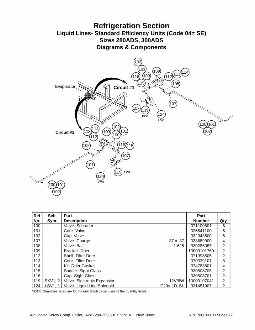
Refrigeration SectionLiquid Lines- Standard Efficiency Units (Code 04= SE)
Sizes 280ADS, 300ADSDiagrams & Components
107 119
107
124
Circuit #1
Circuit #2 102
101100
113
108
112114109
100
102
101
116
115
109100
102101
116 115
107
119124
113112
114
108
107
102
101100
Ref Sch. Part Part No. Sym. Description Number Qty. 100 Valve- Schrader 071100801 6 101 Core- Valve 026541100 6 102 Cap- Valve 032943500 6 107 Valve- Charge .37 x .37 038689900 4 108 Valve- Ball 1.625 330286087 2 109 Bracket- Drier 10000101769 2 112 Shell- Filter Drier 071993505 2 113 Core- Filter Drier 070339101 8 114 Kit- Drier Gasket 074783601 4 115 Saddle- Sight Glass 330508705 2 116 Cap- Sight Glass 330508701 2 119 EXV1, 2 Valve- Electronic Expansion 12V/6W 10000107041 2 124 LSV1, 2 Valve- Liquid Line Solenoid C29= LD, SL 331451007 2
Evaporator
LSV2
LSV1
NOTE: Quantities listed are for the unit. Each circuit uses ½ the quantity listed.
EXV1
EXV2

Air Cooled Screw Comp. Chiller, AWS 280-350 50Hz Vint. A New 08/09 RPL 700014100 / Page 18
Refrigeration SectionLiquid Lines with Economizer- High Efficiency Units (Code 04= HE)
Sizes 300ADH, 320ADH, 350ADHDiagrams
116
115
From Economizer S4
109
112
204
101
201
200
100
102101
107
119
107
124
101
100
102
21
102
101100
Line Between Economizer and Compressor
Detail
ESV_
To Evaporator
From Economizer S2
S1S4
S2S3
Economizer
Connects To Evaporator
To
S1
From Condenser
From Liquid Line Tee
Liquid
Line
Tee
To Compressor
From
Economizer
S4
To Compressor
Compressor Economizer Connection
Detail
102
101100
102
101100
From C
ondenser
Circuit 1 Shown(Circuit 2 has same components)
Condenser to EconomizerDetail
Economizer to Evaporator
Detail
Circuit 1
Circuit 2
From ESV
Equalization
Tube
Evaporator
6
100 102 114
108
113
TXV_
EXV_
LSV_
Air Cooled Screw Comp. Chiller, AWS 280-350 50Hz Vint. A New 08/09 RPL 700014100 / Page 19
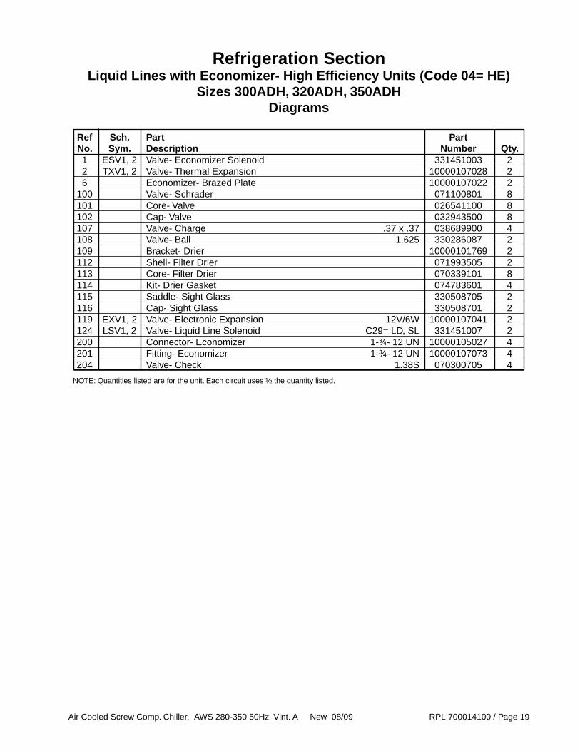
Refrigeration SectionLiquid Lines with Economizer- High Efficiency Units (Code 04= HE)
Sizes 300ADH, 320ADH, 350ADHDiagrams
Ref Sch. Part Part No. Sym. Description Number Qty. 1 ESV1, 2 Valve- Economizer Solenoid 331451003 2 2 TXV1, 2 Valve- Thermal Expansion 10000107028 2 6 Economizer- Brazed Plate 10000107022 2 100 Valve- Schrader 071100801 8 101 Core- Valve 026541100 8 102 Cap- Valve 032943500 8 107 Valve- Charge .37 x .37 038689900 4 108 Valve- Ball 1.625 330286087 2 109 Bracket- Drier 10000101769 2 112 Shell- Filter Drier 071993505 2 113 Core- Filter Drier 070339101 8 114 Kit- Drier Gasket 074783601 4 115 Saddle- Sight Glass 330508705 2 116 Cap- Sight Glass 330508701 2 119 EXV1, 2 Valve- Electronic Expansion 12V/6W 10000107041 2 124 LSV1, 2 Valve- Liquid Line Solenoid C29= LD, SL 331451007 2 200 Connector- Economizer 1-¾- 12 UN 10000105027 4 201 Fitting- Economizer 1-¾- 12 UN 10000107073 4 204 Valve- Check 1.38S 070300705 4
NOTE: Quantities listed are for the unit. Each circuit uses ½ the quantity listed.

Air Cooled Screw Comp. Chiller, AWS 280-350 50Hz Vint. A New 08/09 RPL 700014100 / Page 20
Refrigeration SectionCondenser Coils and Fans
Components
100 200
4
2
1
3
5
Condenser Section
Fan Detail
Fan Location Detail
Dis
char
ge
En
d
Dis
char
ge
En
d
M101 M102 M103 M104 M105 M106 M107 M108
M201 M202 M203 M204 M205 M206 M207 M208
M101 M102 M103 M104 M105 M106 M107 M108
M201 M202 M203 M204 M205 M206 M207 M208
M109 M110
M209 M210
AWS 280, 300
AWS 320, 350
Unit Sizes Ref Sch. Part Part 280, 320, No. Sym. Description Number 300 350 1 Panel- Fan Deck 10000108765 16 20 2 Grille- Fan 10000107008 16 20 3 Bracket- Fan Motor 10000100048 64 80 4 Blade- Fan 10000107009 16 20 5 M*** Motor- Fan 1.4 HP 10000108803 16 20 50 WAA Sensor- Outdoor Air 1 193414601 1 1 100 Coils- Condenser Circuit 1 2
200 Coils- Condenser Circuit 2 2
50
1 Mounted to Condenser Coil tubesheet behind the switch box.2 Contact McQuay Parts.***= Fan number 101 - 212.
Air Cooled Screw Comp. Chiller, AWS 280-350 50Hz Vint. A New 08/09 RPL 700014100 / Page 21
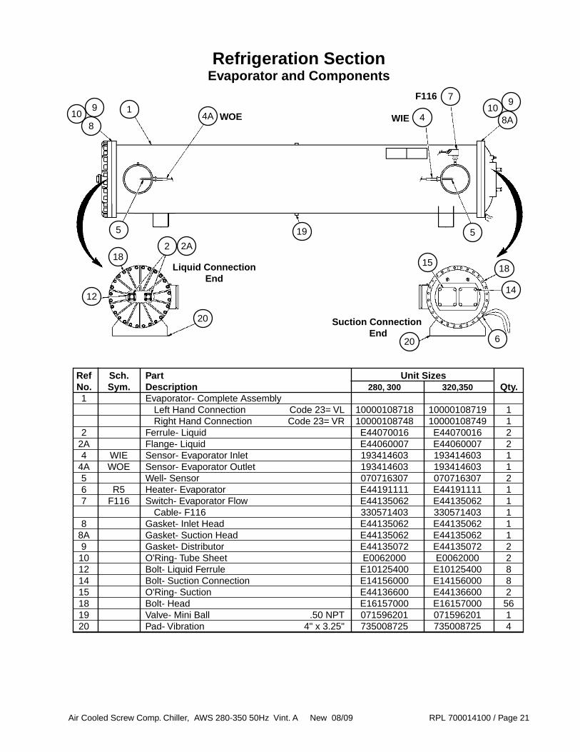
Refrigeration SectionEvaporator and Components
Ref Sch. Part Unit Sizes No. Sym. Description 280, 300 320,350 Qty. 1 Evaporator- Complete Assembly Left Hand Connection Code 23= VL 10000108718 10000108719 1 Right Hand Connection Code 23= VR 10000108748 10000108749 1 2 Ferrule- Liquid E44070016 E44070016 2 2A Flange- Liquid E44060007 E44060007 2 4 WIE Sensor- Evaporator Inlet 193414603 193414603 1 4A WOE Sensor- Evaporator Outlet 193414603 193414603 1 5 Well- Sensor 070716307 070716307 2 6 R5 Heater- Evaporator E44191111 E44191111 1 7 F116 Switch- Evaporator Flow E44135062 E44135062 1 Cable- F116 330571403 330571403 1 8 Gasket- Inlet Head E44135062 E44135062 1 8A Gasket- Suction Head E44135062 E44135062 1 9 Gasket- Distributor E44135072 E44135072 2 10 O'Ring- Tube Sheet E0062000 E0062000 2 12 Bolt- Liquid Ferrule E10125400 E10125400 8 14 Bolt- Suction Connection E14156000 E14156000 8 15 O'Ring- Suction E44136600 E44136600 2 18 Bolt- Head E16157000 E16157000 56 19 Valve- Mini Ball .50 NPT 071596201 071596201 1 20 Pad- Vibration 4" x 3.25" 735008725 735008725 4
1
5
4A 4
7
8
6
5
WOE WIE
F116
218
20
12
2A
109
Liquid Connection End
Suction Connection End
20
14
1518
19
8A10
9

Air Cooled Screw Comp. Chiller, AWS 280-350 50Hz Vint. A New 08/09 RPL 700014100 / Page 22
Base Frame GrillesCode 28= F, C
Sizes 280, 300A Shown
Unit Size Ref Part Part No. Description Number 1 Grille- Base 1 10000108704 16 16 20 20 2 Grille- Left Hand Rear 2 10000108705 1 1 1 1 3 Grille- Right Hand Rear 2 10000108706 1 1 1 1 4 Grille- Front 2 10000108707 1 1 1 1
280A
300A
320A
350A
3
14
2
1 Each base grille is attached using four (4) screws p/n 331578401.2 Each front or rear grille is attached using six (6) screws p/n 331578401.

Air Cooled Screw Comp. Chiller, AWS 280-350 50Hz Vint. A New 08/09 RPL 700014100 / Page 23
Base Frame LouversCode 28= B
Sizes 280A & 300A
Unit Size Ref Part Part No. Description Number 1 Louvered Panel- Front 1 10000101794 1 1 1 1 2 Louvered Panel- Rear Bottom 2 10000101795 1 1 1 1 3 Louvered Panel- Rear Top 1 10000101796 1 1 1 1 4 Louvered Panel- Side 3 10000101797 12 12 16 16 5 Louvered Panel- Side 3 10000101798 2 2 2 2 6 Louvered Panel- Side 3 10000101799 2 2 2 2
280A
300A
320A
350A
3
1
4 2
1 Each bottom end louvered panel is attached using ten (10) screws p/n 331578401.2 Each top rear louvered panel is attached using twelve (12) screws p/n 331578401.3 Each top rear louvered panel is attached using six (6) screws p/n 331578401.
4
44
6
5
6
5
Sizes 320A & 350A
3
44
6
5
1
2
4
45
6

Air Cooled Screw Comp. Chiller, AWS 280-350 50Hz Vint. A New 08/09 RPL 700014100 / Page 24
Coil LouversCode 28= L, B, C
Size 300A Shown
Unit Size Ref Part Part No. Description Number 2 Louvered Panel- Coil 1 10000101793 16 16 20 20
280A
300A
320A
350A
2
1 Each coil louver is attached using six (6) screws p/n 331578401.
Coil GrillesCode 28= G, F
Size 300A Shown
Unit Size Ref Part Part No. Description Number 1 Grille- Coil 1 10000107007 16 16 20 20
280A
300A
320A
350A
1
1 Each coil louver is attached using six (6) screws p/n 331578401.
Air Cooled Screw Comp. Chiller, AWS 280-350 50Hz Vint. A New 08/09 RPL 700014100 / Page 25
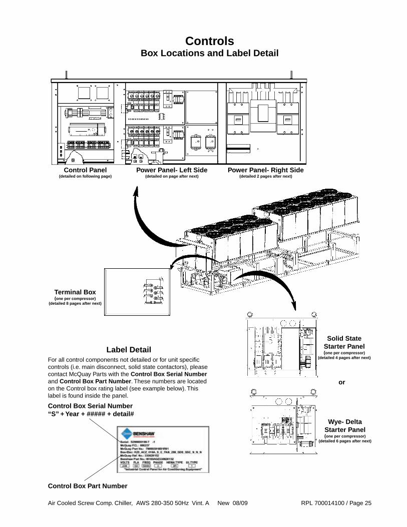
ControlsBox Locations and Label Detail
Control Panel Power Panel- Left Side Power Panel- Right Side (detailed on following page) (detailed on page after next) (detailed 2 pages after next)
Solid State Starter Panel(one per compressor)
(detailed 4 pages after next)
Wye- DeltaStarter Panel(one per compressor)
(detailed 6 pages after next)
or
Terminal Box(one per compressor)
(detailed 8 pages after next)
For all control components not detailed or for unit specific controls (i.e. main disconnect, solid state contactors), please contact McQuay Parts with the Control Box Serial Number and Control Box Part Number. These numbers are located on the Control box rating label (see example below). This label is found inside the panel.
Control Box Serial Number“S” + Year + ##### + detail#
Control Box Part Number
Label Detail

Air Cooled Screw Comp. Chiller, AWS 280-350 50Hz Vint. A New 08/09 RPL 700014100 / Page 26
ControlsControl Panel Detail
F59 F12Q12 K11 AC REC1
UC FC
Q0
Q1
Q2
Sch. Part Part Sym. Description Number Qty. Q0 Switch- Unit Shut Off 300046456 1 Q1 Switch- Pumpdown Circuit #1 300046456 1 Q2 Switch- Pumpdown Circuit #2 300046456 1 Q11 Switch- Emergency Stop 1 300046448 1 Q12 Circuit Breaker 300046447 1 K11 Relay- Emergency Stop 300046445 1 F12 Fuse- Outlet 300046446 1 F59 Fuse- Evaporator Heater Protection 300046455 1 REC1 Receptacle 330472601 1 UC Controller- MicroTech III 193407301 1 FC Expansion Controller- Fans 193407601 1 AC Expansion Controller- Alarms 193407501 1
Q11
1 Mounted through the door.
Air Cooled Screw Comp. Chiller, AWS 280-350 50Hz Vint. A New 08/09 RPL 700014100 / Page 27
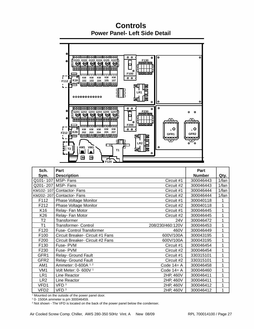
ControlsPower Panel- Left Side Detail
K16KM102F112
T2
GFR1
UC F230
T1
Sch. Part Part Sym. Description Number Qty. Q101- 107 MSP- Fans Circuit #1 300046443 1/fan Q201- 207 MSP- Fans Circuit #2 300046443 1/fan KM102- 107 Contactor- Fans Circuit #1 300046444 1/fan KM202- 207 Contactor- Fans Circuit #2 300046444 1/fan F112 Phase Voltage Monitor Circuit #1 300040118 1 F212 Phase Voltage Monitor Circuit #2 300040118 1 K16 Relay- Fan Motor Circuit #1 300046445 1 K26 Relay- Fan Motor Circuit #2 300046445 1 T2 Transformer 24V 300046472 1 T1 Transformer- Control 208/230/460:120V 300046453 1 F120 Fuse- Control Transformer 460V 300046449 1 F100 Circuit Breaker- Circuit #1 Fans 600V/100A 300043195 1 F200 Circuit Breaker- Circuit #2 Fans 600V/100A 300043195 1 F130 Fuse- PVM Circuit #1 300046454 1 F230 Fuse- PVM Circuit #2 300046454 1 GFR1 Relay- Ground Fault Circuit #1 330315101 1 GFR2 Relay- Ground Fault Circuit #2 330315101 1 AM1 Ammeter: 0-600A 1, 2 Code 14= A 300046458 1 VM1 Volt Meter: 0- 600V 1 Code 14= A 300046460 1 LR1 Line Reactor 2HP, 460V 300046411 1 LR2 Line Reactor 2HP, 460V 300046411 1 VFD1 VFD 3 2HP, 460V 300046412 1 VFD2 VFD 3 2HP, 460V 300046412 1
GFR2
F130
F100
F200
F212
F120
KM103
KM104
KM105
KM107
Q101 Q102 Q103 Q104 Q105 Q107
K26KM202
KM203
KM204
KM205
KM207
Q201 Q202 Q203 Q204 Q205 Q207
AM1 VM1
1 Mounted on the outside of the power panel door.2 0- 1500A ammeter is p/n 300046459.3 Not shown - The VFD is located on the back of the power panel below the condenser.
LR2
LR1
Air Cooled Screw Comp. Chiller, AWS 280-350 50Hz Vint. A New 08/09 RPL 700014100 / Page 28
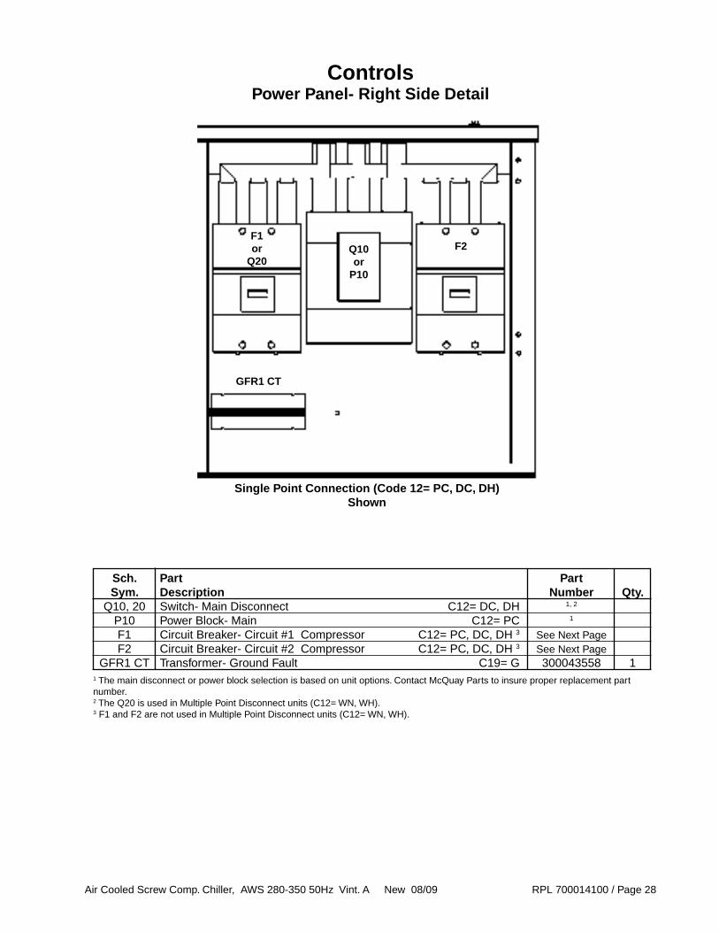
ControlsPower Panel- Right Side Detail
Sch. Part Part Sym. Description Number Qty. Q10, 20 Switch- Main Disconnect C12= DC, DH 1, 2
P10 Power Block- Main C12= PC 1
F1 Circuit Breaker- Circuit #1 Compressor C12= PC, DC, DH 3 See Next Page F2 Circuit Breaker- Circuit #2 Compressor C12= PC, DC, DH 3 See Next Page GFR1 CT Transformer- Ground Fault C19= G 300043558 1
Q10or
P10
F1or
Q20F2
GFR1 CT
1 The main disconnect or power block selection is based on unit options. Contact McQuay Parts to insure proper replacement part number.2 The Q20 is used in Multiple Point Disconnect units (C12= WN, WH). 3 F1 and F2 are not used in Multiple Point Disconnect units (C12= WN, WH).
Single Point Connection (Code 12= PC, DC, DH) Shown

Air Cooled Screw Comp. Chiller, AWS 280-350 50Hz Vint. A New 08/09 RPL 700014100 / Page 29
Unit Size Sch. Part Part 280 300 Sym. Description Number ADS ADS F1 Circuit Breaker- Circuit #1 Single Point (C12= PC, DC) 400A 300046490 1 Single Point (C12= PC, DC) 600A 300046486 1 SP High Short Circuit (C12= DH) 400A 300046491 1 SP High Short Circuit (C12= DH) 600A 300046487 1
F2 Circuit Breaker- Circuit #2 Single Point (C12= PC, DC) 600A 300046486 1 1 SP High Short Circuit (C12= DH) 600A 300046487 1 1
ControlsPower Panel- Right Side Detail, Continued
Circuit Breakers
Standard Efficiency Units (Code 04= SE)
High Efficiency Units (Code 04= HE)
Unit Size Sch. Part Part 300 320 350 Sym. Description Number ADH ADH ADH F1 Circuit Breaker- Circuit #1 Single Point (C12= PC, DC) 400A 300046490 1 1 Single Point (C12= PC, DC) 600A 300046486 1 SP High Short Circuit (C12= DH) 400A 300046491 1 1 SP High Short Circuit (C12= DH) 600A 300046487 1
F2 Circuit Breaker- Circuit #1 Single Point (C12= PC, DC) 400A 300046490 1 Single Point (C12= PC, DC) 600A 300046486 1 1 SP High Short Circuit (C12= DH) 400A 300046491 1 SP High Short Circuit (C12= DH) 600A 300046487 1 1

Air Cooled Screw Comp. Chiller, AWS 280-350 50Hz Vint. A New 08/09 RPL 700014100 / Page 30
ControlsSolid State Starter Panel- Circuit 1
Code 09= SS
M1
KM1-1
T20-1
MP1
CC1
EEXV1
F0-1
MPR-1
KT-1
LJV-1
K2B-1
Unit Size 300 320,350 380 405
Sch. Part Part Sym. Description Number KM1-1 Contactor- Solid State 1 1 1 1 1 K2B-1 Contactor- Turbo 349934724 1 1 1 1 KT-1 Relay- Turbo Solenoid 300046470 1 1 1 1 LJV-1 Relay- Liquid Injection 300046470 1 1 1 1 F0-1 MSP- Heater 300044140 1 1 1 1 MPR-1 Relay- Motor Protection 330278110 1 1 1 1 EEXV1 Controller- Expansion Valve 300046465 1 1 1 1 CC1 Controller- Circuit 193407501 1 1 1 1 T20-1 Transformer- 120V to 24V 300046466 1 1 1 1 MP1 Motor Protector 330343902 1 1 1 1
400/
50/3
400/
50/3
400/
50/3
400/
50/3
1 The Solid State contactors are specific to the unit. Contact McQuay Parts with the information from the control box data plate for replacement.
Air Cooled Screw Comp. Chiller, AWS 280-350 50Hz Vint. A New 08/09 RPL 700014100 / Page 31
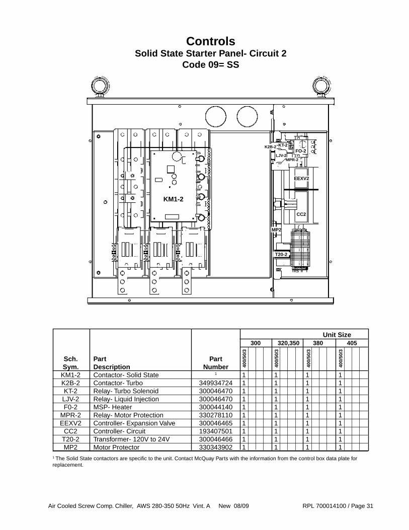
ControlsSolid State Starter Panel- Circuit 2
Code 09= SS
KM1-2
T20-2
MP2
CC2
EEXV2
FO-2
MPR-2
KT-2
LJV-2
K2B-2
Unit Size 300 320,350 380 405
Sch. Part Part Sym. Description Number KM1-2 Contactor- Solid State 1 1 1 1 1 K2B-2 Contactor- Turbo 349934724 1 1 1 1 KT-2 Relay- Turbo Solenoid 300046470 1 1 1 1 LJV-2 Relay- Liquid Injection 300046470 1 1 1 1 F0-2 MSP- Heater 300044140 1 1 1 1 MPR-2 Relay- Motor Protection 330278110 1 1 1 1 EEXV2 Controller- Expansion Valve 300046465 1 1 1 1 CC2 Controller- Circuit 193407501 1 1 1 1 T20-2 Transformer- 120V to 24V 300046466 1 1 1 1 MP2 Motor Protector 330343902 1 1 1 1
400/
50/3
400/
50/3
400/
50/3
400/
50/3
1 The Solid State contactors are specific to the unit. Contact McQuay Parts with the information from the control box data plate for replacement.
Air Cooled Screw Comp. Chiller, AWS 280-350 50Hz Vint. A New 08/09 RPL 700014100 / Page 32
T20-1
MP1
CC1
EEXV1
FO-1
MPR-1
KT-1
LJV-1
K2B-1
Unit Size 300, 320 350 380 405
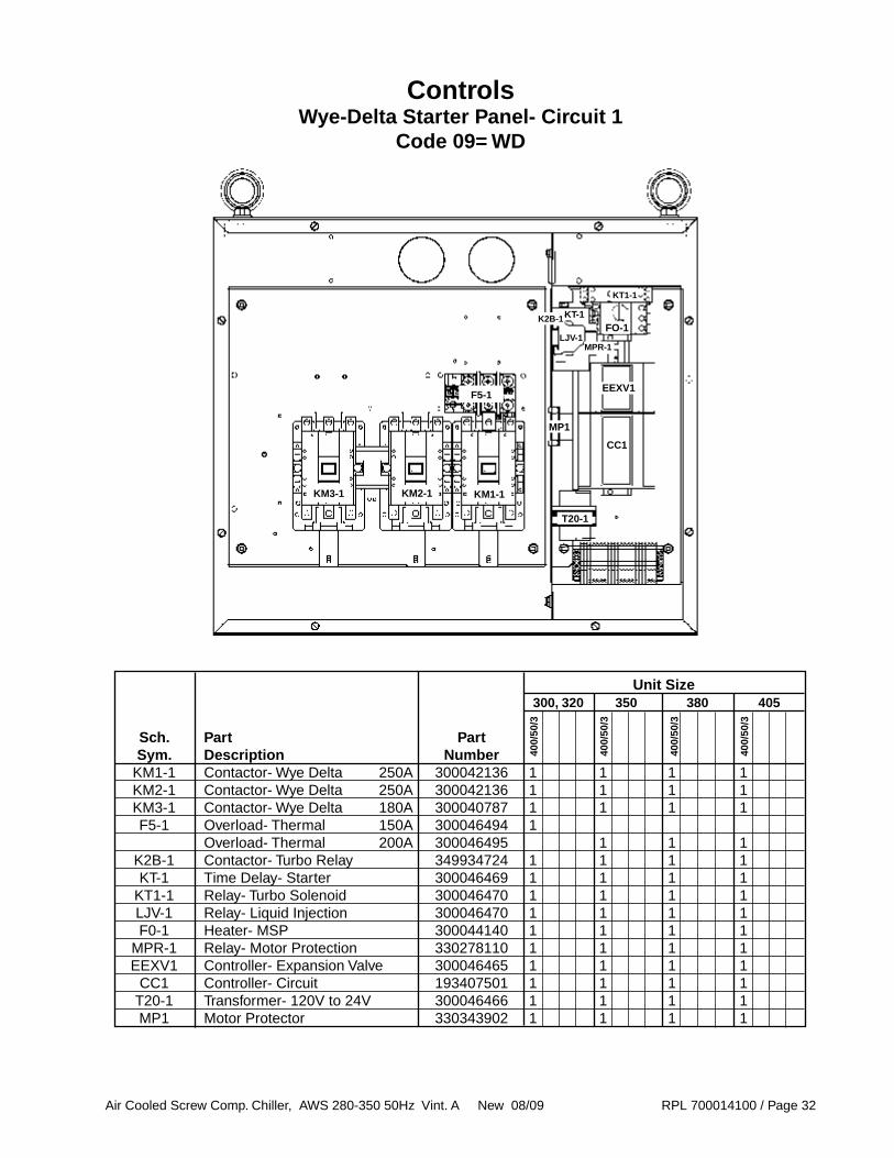
Sch. Part Part Sym. Description Number KM1-1 Contactor- Wye Delta 250A 300042136 1 1 1 1 KM2-1 Contactor- Wye Delta 250A 300042136 1 1 1 1 KM3-1 Contactor- Wye Delta 180A 300040787 1 1 1 1 F5-1 Overload- Thermal 150A 300046494 1 Overload- Thermal 200A 300046495 1 1 1 K2B-1 Contactor- Turbo Relay 349934724 1 1 1 1 KT-1 Time Delay- Starter 300046469 1 1 1 1 KT1-1 Relay- Turbo Solenoid 300046470 1 1 1 1 LJV-1 Relay- Liquid Injection 300046470 1 1 1 1 F0-1 Heater- MSP 300044140 1 1 1 1 MPR-1 Relay- Motor Protection 330278110 1 1 1 1 EEXV1 Controller- Expansion Valve 300046465 1 1 1 1 CC1 Controller- Circuit 193407501 1 1 1 1 T20-1 Transformer- 120V to 24V 300046466 1 1 1 1 MP1 Motor Protector 330343902 1 1 1 1
400/
50/3
400/
50/3
400/
50/3
400/
50/3
KT1-1
KM3-1 KM2-1 KM1-1
F5-1
ControlsWye-Delta Starter Panel- Circuit 1
Code 09= WD

Air Cooled Screw Comp. Chiller, AWS 280-350 50Hz Vint. A New 08/09 RPL 700014100 / Page 33
T20-2
MP2
CC2
EEXV2
FO-2
MPR-2
KT-2
LJV-2
K2B-2
Unit Size 300 320, 350 380 405
Sch. Part Part Sym. Description Number KM1-2 Contactor- Wye Delta 250A 300042136 1 1 1 1 KM2-2 Contactor- Wye Delta 250A 300042136 1 1 1 1 KM3-2 Contactor- Wye Delta 180A 300040787 1 1 1 1 F5-2 Overload- Thermal 150A 300046494 1 Overload- Thermal 200A 300046495 1 1 1 K2B-2 Contactor- Turbo Relay 349934724 1 1 1 1 KT-2 Time Delay- Starter 300046469 1 1 1 1 KT1-2 Relay- Turbo Solenoid 300046470 1 1 1 1 LJV-2 Relay- Liquid Injection 300046470 1 1 1 1 F0-2 Heater- MSP 300044140 1 1 1 1 MPR-2 Relay- Motor Protection 330278110 1 1 1 1 EEXV2 Controller- Expansion Valve 300046465 1 1 1 1 CC2 Controller- Circuit 193407501 1 1 1 1 T20-2 Transformer- 120V to 24V 300046466 1 1 1 1 MP2 Motor Protector 330343902 1 1 1 1
400/
50/3
400/
50/3
400/
50/3
400/
50/3
KT1-2
KM3-2 KM2-2 KM1-2
F5-2
ControlsWye-Delta Starter Panel- Circuit 2
Code 09= WD

Air Cooled Screw Comp. Chiller, AWS 280-350 50Hz Vint. A New 08/09 RPL 700014100 / Page 34
ControlsTerminal Box
50
Unit Size 300 320,350 380 405
Ref. Sch. Part Part No. Sym. Description Number 50 Terminal Plate - Motor 330875701 1 1 1 1
400/
50/3
400/
50/3
400/
50/3
400/
50/3
Air Cooled Screw Comp. Chiller, AWS 280-350 50Hz Vint. A New 08/09 RPL 700014100 / Page 35
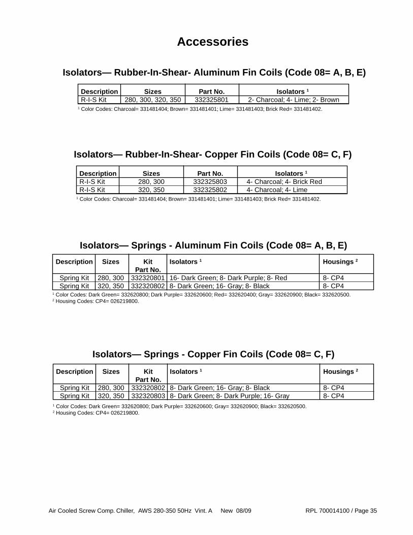
Accessories
Isolators— Rubber-In-Shear- Aluminum Fin Coils (Code 08= A, B, E)
Description Sizes Part No. Isolators 1
R-I-S Kit 280, 300, 320, 350 332325801 2- Charcoal; 4- Lime; 2- Brown1 Color Codes: Charcoal= 331481404; Brown= 331481401; Lime= 331481403; Brick Red= 331481402.
Isolators— Springs - Aluminum Fin Coils (Code 08= A, B, E)
Description Sizes Kit Isolators 1 Housings 2
Part No. Spring Kit 280, 300 332320801 16- Dark Green; 8- Dark Purple; 8- Red 8- CP4 Spring Kit 320, 350 332320802 8- Dark Green; 16- Gray; 8- Black 8- CP41 Color Codes: Dark Green= 332620800; Dark Purple= 332620600; Red= 332620400; Gray= 332620900; Black= 332620500.2 Housing Codes: CP4= 026219800.
Isolators— Springs - Copper Fin Coils (Code 08= C, F)
Isolators— Rubber-In-Shear- Copper Fin Coils (Code 08= C, F)
Description Sizes Part No. Isolators 1
R-I-S Kit 280, 300 332325803 4- Charcoal; 4- Brick Red R-I-S Kit 320, 350 332325802 4- Charcoal; 4- Lime1 Color Codes: Charcoal= 331481404; Brown= 331481401; Lime= 331481403; Brick Red= 331481402.
Description Sizes Kit Isolators 1 Housings 2
Part No. Spring Kit 280, 300 332320802 8- Dark Green; 16- Gray; 8- Black 8- CP4 Spring Kit 320, 350 332320803 8- Dark Green; 8- Dark Purple; 16- Gray 8- CP41 Color Codes: Dark Green= 332620800; Dark Purple= 332620600; Gray= 332620900; Black= 332620500.2 Housing Codes: CP4= 026219800.

Air Cooled Screw Comp. Chiller, AWS 280-350 50Hz Vint. A New 08/09 RPL 700014100 / Page 36
Accessories
Flow Switches
Description Part No. Flow Switch- Paddle 017503300 Flow Switch Kit- Electronic 332688401 Flow Switch Only 331796201 Cable- Flow Switch 330571404
Sound Enclosure Kit
Description Part No. Complete Kit 332523852
Base Grilles
Description Part No. Base Grille Kit includes grilles and hardware AWS 300 3326881161
AWS 320, 350 3326881201
AWS 380 3326881221
AWS 405 3326881241
1 Part number and locations are detailed in the Cabinet section.
Coil Louvers
Description Part No. Coil Louver Kit includes louvers and hardware AWS 300 3326882161
AWS 320, 350 3326882201
AWS 380 3326882221
AWS 405 3326882241
1 Part number and locations are detailed in the Cabinet section.
Base and Coil Louvers
Description Part No. Base and Coil Louver Kit includes louvers and hardware AWS 300 3326883161
AWS 320, 350 3326883201
AWS 380 3326883221
AWS 405 3326883241
1 Part number and locations are detailed in the Cabinet section.
Air Cooled Screw Comp. Chiller, AWS 280-350 50Hz Vint. A New 08/09 RPL 700014100 / Page 37
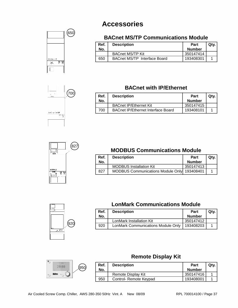
Ref. Description Part Qty. No. Number Remote Display Kit 350147416 1 950 Control- Remote Keypad 193408001 1
BACnet with IP/Ethernet
Ref. Description Part Qty. No. Number MODBUS Installation Kit 350147413 827 MODBUS Communications Module Only 193408401 1
MODBUS Communications Module
Ref. Description Part Qty. No. Number LonMark Installation Kit 350147412 920 LonMark Communications Module Only 193408203 1
LonMark Communications Module
827
700
Accessories
Ref. Description Part Qty. No. Number BACnet MS/TP Kit 350147414 650 BACnet MS/TP Interface Board 193408301 1
BACnet MS/TP Communications Module650
Remote Display Kit
920
950
Ref. Description Part Qty. No. Number BACnet IP/Ethernet Kit 350147415 700 BACnet IP/Ethernet Interface Board 193408101 1


