Download - Cybernetics and Circuits Feedback

p1 RJM 19/09/12 SE1CC11 Cybernetics and Circuits - Feedback A© Dr Richard Mitchell 2012
SE1CC11 Cybernetics and Circuits Feedback – Part ADr Richard Mitchell
Senior Lecturer in CyberneticsSE1CC11 and SE1CA11 introduce fundamental concepts and
applications of Cybernetics – feedback theory, artificial intelligence and Robotics; and they cover Electronic Circuits and Computing. This year there are 5 lectures in Autumn, 10 in Spring on Feedback
Assessment: Laboratory Practicals (see separate timetable)3 hour exam with questions on Feedback, Circuits and Op-amps
Note material used to be in SE1CA5/9 and SE1EA5This year we have reorganised the module
- more on Feedback less on circuits

p2 RJM 19/09/12 SE1CC11 Cybernetics and Circuits - Feedback A© Dr Richard Mitchell 2012
On Blackboard, Books, etc.Lecture Notes on Blackboard and directly on link from
http://www.personal.rdg.ac.uk/~shsmchlr/teach.htm
BUT note it is still important to attend the lecturesas some of the handouts have deliberate gaps to fill
AND I say things that which you should write downSpare copies of notes in School Information Office G47“Custom book” ‘Cybernetics, Circuits and Computing’, Mitchell, Harwin,
Cadenas, Gong, Potter and Warwick, Pearson, ISBN 978-1-78016-067-2
I have set up a ‘discussion board’ on Blackboard
Feel free to ask a question or answer someone else’sTutorial Questions to do on Blackboard – from week 2

p3 RJM 19/09/12 SE1CC11 Cybernetics and Circuits - Feedback A© Dr Richard Mitchell 2012
Feedback SyllabusIntroduction to systems with feedback - show varietyBlock diagram analysis - show what feedback doesPositive and Negative Feedback - and consequencesSystems with Limits - applications of inevitable limitsStatic and Dynamic Systems - dynamics and stabilityFrequency Response AnalysisComputer Modeling of Feedback SystemsNote, aim to cover these topics with minimal mathsFeedback and System Analysis is also covered in lectures on operational amplifiers and circuit theory.Feedback also features in Artificial Intelligence and Robotics

p4 RJM 19/09/12 SE1CC11 Cybernetics and Circuits - Feedback A© Dr Richard Mitchell 2012
Kybernetes (Steersman)
Robots
Neural Nets
Learning Robot
VR
Gaia
All different + use feedback
Cybernetics – a Different Perspective

p5 RJM 19/09/12 SE1CC11 Cybernetics and Circuits - Feedback A© Dr Richard Mitchell 2012
Standard and Cybernetic ApproachesStandard View: Aristotelian (Greek) - Cause & Effect
The (practical) Cybernetic view : Closed Loop –Has Feeback
Irony: Cybernetics comes from a Greek Word!
The Open Loop View
Cause EffectSystem
Cause
Reaction
EffectSystem
p6 RJM 19/09/12 SE1CC11 Cybernetics and Circuits - Feedback A© Dr Richard Mitchell 2012
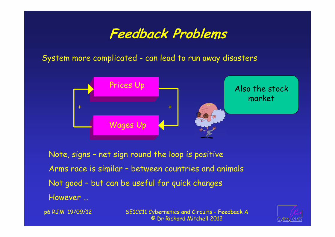
Feedback ProblemsSystem more complicated - can lead to run away disasters
Note, signs – net sign round the loop is positive
Arms race is similar – between countries and animals
Not good – but can be useful for quick changes
However …
Also the stock market
Wages Up
Prices Up
+ +

p7 RJM 19/09/12 SE1CC11 Cybernetics and Circuits - Feedback A© Dr Richard Mitchell 2012
Feedback Advantages - for Control
No control– like havingeyes closed
With control– lookingwhere youare going
This will be illustrated by first considering the steersman
Winds/TidesCourse
BoatGuess
Winds/Tides
Steersman
CourseBoat
Left /Right +-
Net sign -ve

p8 RJM 19/09/12 SE1CC11 Cybernetics and Circuits - Feedback A© Dr Richard Mitchell 2012
As Applied To Other Systems
Speed Control of Car (or other vehicle)
Positioning Robot Gripper
Obstacles
Joint Motors
PositionRobot ArmTurn
/ AntiClock
+-
Winds/Hills
Driver
SpeedCar
Slow /Speed +-

p9 RJM 19/09/12 SE1CC11 Cybernetics and Circuits - Feedback A© Dr Richard Mitchell 2012
Temperature ControlOf Rooms
Of Human Body Sun, Illness, etc
Action
TemperatureBody
Sweat /Shiver +-
Sun, PCs, People
Air Con/Boiler
TemperatureRoom
Heat /Cool +-
p10 RJM 19/09/12 SE1CC11 Cybernetics and Circuits - Feedback A© Dr Richard Mitchell 2012
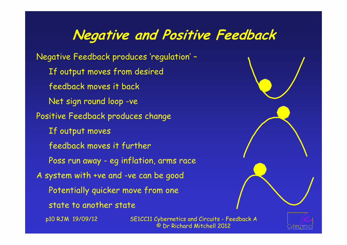
Negative and Positive FeedbackNegative Feedback produces ‘regulation’ –
If output moves from desired
feedback moves it back
Net sign round loop -ve
Positive Feedback produces change
If output moves
feedback moves it further
Poss run away - eg inflation, arms race
A system with +ve and -ve can be good
Potentially quicker move from one
state to another state
p11 RJM 19/09/12 SE1CC11 Cybernetics and Circuits - Feedback A© Dr Richard Mitchell 2012
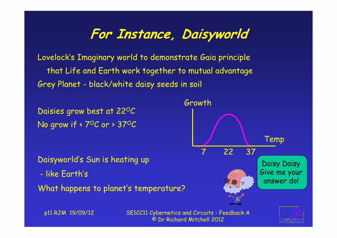
For Instance, DaisyworldLovelock’s Imaginary world to demonstrate Gaia principle
that Life and Earth work together to mutual advantageGrey Planet - black/white daisy seeds in soil
Daisies grow best at 22OCNo grow if < 7OC or > 37OC
Daisyworld’s Sun is heating up
- like Earth’s
What happens to planet’s temperature?
7 22 37
Growth
Temp
Daisy Daisy Give me your answer do!

p12 RJM 19/09/12 SE1CC11 Cybernetics and Circuits - Feedback A© Dr Richard Mitchell 2012
Daisyworld Continued
Note, for long period, temp constant –
better if more species!
Once 7OC: daisies grow,
heating or cooling,
until too hot
Sun
Daisies
TemperaturePlanet
Black /
White
if no life
if life
Time
C
7
22
37Temp
p13 RJM 19/09/12 SE1CC11 Cybernetics and Circuits - Feedback A© Dr Richard Mitchell 2012
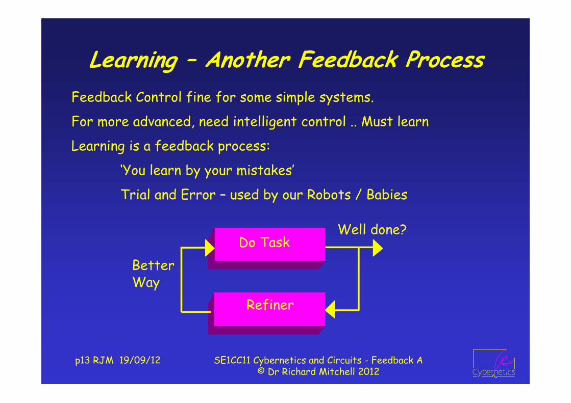
Learning – Another Feedback ProcessFeedback Control fine for some simple systems.
For more advanced, need intelligent control .. Must learn
Learning is a feedback process:
‘You learn by your mistakes’
Trial and Error – used by our Robots / Babies
Refiner
Do Task
WayBetter
Well done?
p14 RJM 19/09/12 SE1CC11 Cybernetics and Circuits - Feedback A© Dr Richard Mitchell 2012
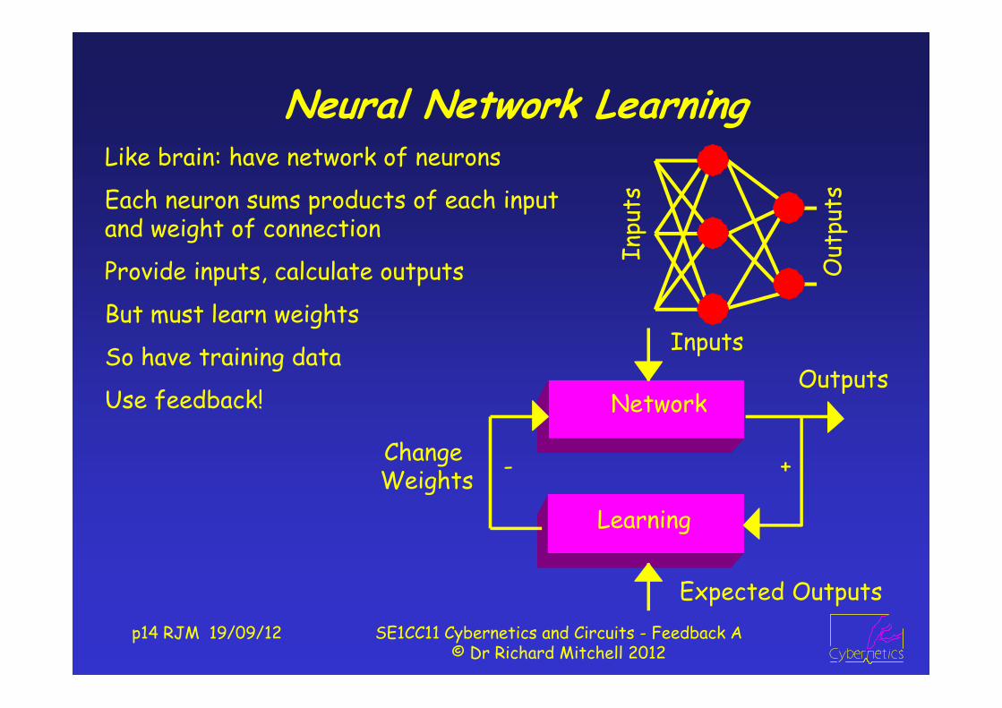
Neural Network LearningLike brain: have network of neurons
Each neuron sums products of each input and weight of connection
Provide inputs, calculate outputs
But must learn weights
So have training data
Use feedback!
Out
puts
Inpu
tsExpected Outputs
Outputs
LearningWeightsChange
Inputs
Network
+-

p15 RJM 19/09/12 SE1CC11 Cybernetics and Circuits - Feedback A© Dr Richard Mitchell 2012
Human Computer InteractionJust positioning a mouse is a feedback process
Ultimate HCI is ‘Virtual Reality’
Also, Augmented Reality - mixed real and virtual world,
Tele-operation - remote control where operator given input to suggest he/she at remote location.
Needs force feedback and touch – ‘haptics’
Human
Computer
-ment
Image
Move +-

p16 RJM 19/09/12 SE1CC11 Cybernetics and Circuits - Feedback A© Dr Richard Mitchell 2012
Cybernetics Is In Fact Not NewWatt Steam Engine Governor
Controlling Speed of Steam Engine
By affecting amount of steam from boiler to engine
In fact governor borrowed from Wind Mills
you’re in control when you know what to do with the governor’s
ballsValveThrottle
Steamto engine
from BoilerSteam EngineCoupled to

p17 RJM 19/09/12 SE1CC11 Cybernetics and Circuits - Feedback A© Dr Richard Mitchell 2012
First Man Made Feedback System250 BC Water Clock:
Constant Flow into vessel starting at Sun up
Height of water indicates time
But need to ensure constant flow
So have second vessel, with hole, which keep full ….
regulator
vesselclock
watersupply
vessel
valvefloat
Cybernetics began in the
toilet!
p18 RJM 19/09/12 SE1CC11 Cybernetics and Circuits - Feedback A© Dr Richard Mitchell 2012
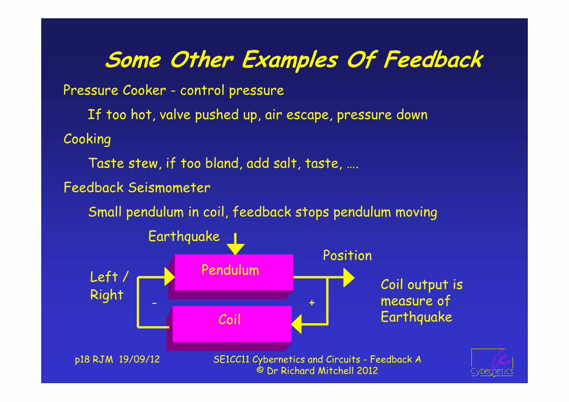
Some Other Examples Of FeedbackPressure Cooker - control pressure
If too hot, valve pushed up, air escape, pressure down
Cooking
Taste stew, if too bland, add salt, taste, ….
Feedback Seismometer
Small pendulum in coil, feedback stops pendulum moving
Coil output is measure of EarthquakeCoil
PositionPendulumLeft /
Right
Earthquake
+-

p19 RJM 19/09/12 SE1CC11 Cybernetics and Circuits - Feedback A© Dr Richard Mitchell 2012
SummaryThus have demonstrated the principle of feedback
And that it can be applied to many types of system
technological as well as animal and (briefly) economic
Next week we will look at more systems
including a world of daisies … environmental
mention positive and negative feedback
consider systems with inherent feedback
and introduce the generation and analysis
of models of feedback systems
p20 RJM 19/09/12 SE1CC11 Cybernetics and Circuits - Feedback A© Dr Richard Mitchell 2012
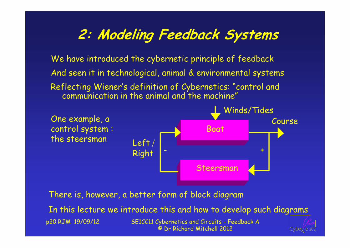
2: Modeling Feedback SystemsWe have introduced the cybernetic principle of feedbackAnd seen it in technological, animal & environmental systemsReflecting Wiener’s definition of Cybernetics: “control and
communication in the animal and the machine”Winds/Tides
Steersman
CourseBoat
Left /Right +-
One example, a control system : the steersman
There is, however, a better form of block diagram
In this lecture we introduce this and how to develop such diagrams

p21 RJM 19/09/12 SE1CC11 Cybernetics and Circuits - Feedback A© Dr Richard Mitchell 2012
Classical Feedback Control System
Output (‘actual’), fedback, compared with input (‘desired’).
Comparison : subtract actual from desired (see + / - in ‘summer’)
If Actual ≠ Desired have Error processed by Control block
makes ‘Device’ change its ‘actual’ state.
i.e. See what have got, if not what want, do something!
Device under control affected by external disturbance
Often draw block diagram as follows
Desired Actual
Disturbance
Controller
Error
Device

p22 RJM 19/09/12 SE1CC11 Cybernetics and Circuits - Feedback A© Dr Richard Mitchell 2012
Block Diagram ComponentsBy way of explanation : these are components of block diagrams
Note A, B, C are signals (voltages, positions, speeds, etc)
In Control System, Error = Desired – Actual; for instance
Block : X defines component changing A to B Take off : B = C = A
Summing Junctions : C = A - B
A BX A CB
A
B
C A
B
CA
B
C
C = A - BC = A + B

p23 RJM 19/09/12 SE1CC11 Cybernetics and Circuits - Feedback A© Dr Richard Mitchell 2012
Fuller DiagramReally ought to include Sensor and Actuator:
Actuator turns control signal to form so can drive device.
Sensor measures Actual, converts to form so can compare.
NB Feedback aim: Error = 0, so Measured Actual = Desired
Fine if measurement correct, problematic otherwise
e.g. if speedo’ says 30mph if doing 35mph or league tables
Desired ActualDisturbance
Controller
Error
DeviceActuator
Sensor

p24 RJM 19/09/12 SE1CC11 Cybernetics and Circuits - Feedback A© Dr Richard Mitchell 2012
Developing System ModelsTo develop model: divide system into manageable parts
Then bring together to form whole model. e.g. A bike.
Legs MovementPedals WheelChain
Legs MovementBike
Legs MovementBike
Wind
Desired Speed
Actual Speed
WindHuman
Legs
Bike
A system with inherent feedback, there are others

p25 RJM 19/09/12 SE1CC11 Cybernetics and Circuits - Feedback A© Dr Richard Mitchell 2012
Example – Two tanks connected by pipe
IF
O
Pipe has resistance – affects amount of flow through it
Tanks have capacity –affects rate at which height of liquid in tank changes
Weight Density*g*VolumePressure = = Area Area
Density * g*Height * Area = = constant * HeightArea
Liquid flows due to difference in pressure at ends of pipe
So difference in Height causes Flow through pipe

Block Diagram of Tanks
p26 RJM 19/09/12 SE1CC11 Cybernetics and Circuits - Feedback A© Dr Richard Mitchell 2012
IF
O
Height difference I-O → Flow F
Flow F → O to rise
I OPipe
I - O
Tank
FHence, block diagram
System reaches final state ‘steady state’, when signals constant
This will be when F = 0, which is when O = I
NB: summer does I – O: so signals I and O same type (units m)
Flow F is volume moving at rate : units m3 / s

p27 RJM 19/09/12 SE1CC11 Cybernetics and Circuits - Feedback A© Dr Richard Mitchell 2012
Analogous SystemsOften same model can apply to two different system typesWater system
water flows thru pipe as pressure difference across pipepipe has resistance (affected by its size): restricts flowwater flows into tank; means height of water increasesspeed at which height incr affected by tank’s capacity
Electronic systemcurrent flows thru resistor, as voltage difference across itresistor has resistance – which resists current flowcurrent flows into capacitor, so voltage across it increasesspeed of voltage incr affected by capacitor’s capacitance

p28 RJM 19/09/12 SE1CC11 Cybernetics and Circuits - Feedback A© Dr Richard Mitchell 2012
Resistor-Capacitor System
Voltage across Resistor is E – V : that over R sets I
I into capacitor causes V to increase : so block diagram
E VRes
E - V
Cap
I
VCE
I
RVoltage input, E, from battery.
Output V, across capacitor
Final, Steady value, when V = E, then I = 0
E and V measured in volts V, I measured in amps A

p29 RJM 19/09/12 SE1CC11 Cybernetics and Circuits - Feedback A© Dr Richard Mitchell 2012
Motor
Vin applied to armature circuit → current → force F to move
Frictional force (f * velocity, v) opposes motion
Net force is F – f*v = motor mass * acceleration (Newton’s 2nd law)
Acceleration means velocity increases
Steady state, when v such that friction force = F as set by Vin
Signal Units: Vin in Volts, forces in Newtons (N), velocity (m/s)
v = velocity
Vin
vArmature
Net Force
Mass
friction
Vin F
fv
p30 RJM 19/09/12 SE1CC11 Cybernetics and Circuits - Feedback A© Dr Richard Mitchell 2012
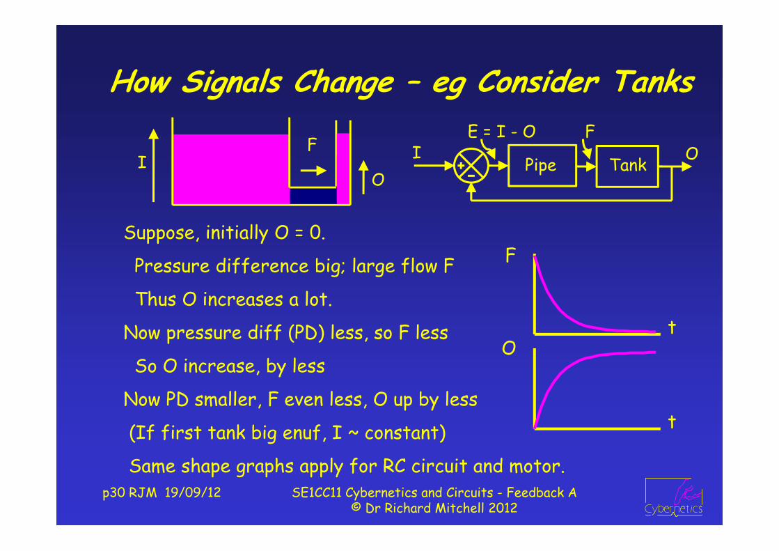
How Signals Change – eg Consider Tanks
Suppose, initially O = 0.
Pressure difference big; large flow F
Thus O increases a lot.
Now pressure diff (PD) less, so F less
So O increase, by less
Now PD smaller, F even less, O up by less
(If first tank big enuf, I ~ constant)
FI
O
F
tO
t
I OPipe
E = I - O
Tank
F
Same shape graphs apply for RC circuit and motor.

p31 RJM 19/09/12 SE1CC11 Cybernetics and Circuits - Feedback A© Dr Richard Mitchell 2012
Blocks and Transfer FunctionsOur block diagrams include blocks, such as:
X is Transfer Function,
Defines how signal A is transferred to signal B : X = B/A
= *X (or X * ) or = XBB A AA
A BX
We now start to define how A becomes B

Gains and Transfer Functions
p32 RJM 19/09/12 SE1CC11 Cybernetics and Circuits - Feedback A© Dr Richard Mitchell 2012
Sometimes call Transfer Function X the ‘gain’ of the block,
X could be a number say 10;
B is 10 times A, B and A are signals of same type
But X can change signal types –
eg for Resistor: A = Voltage; B is Current ; X is 1/Resistance
Current (in Amps) = Voltage (in Volts) * (1/Resistance)
V I1/R
Still like a ‘gain’, as I is number * V
eg suppose V = 2V, R = 4Ω, then I = 2 * ¼ = 0.5A
NB resistance measured in Ω1/R in seimens

Some Examples
p33 RJM 19/09/12 SE1CC11 Cybernetics and Circuits - Feedback A© Dr Richard Mitchell 2012
V (voltage)
V I1/R
I VR
Extensionx
Forcex F
k
V = I * RI = V * 1/R
F = k * x
Resistor
Spring
Mass F1/m
AA = F * 1/m
F = v * f
Damper Dashpot(for friction)
v Ff
FMass
A
On Integrators
p34 RJM 19/09/12 SE1CC11 Cybernetics and Circuits - Feedback A© Dr Richard Mitchell 2012
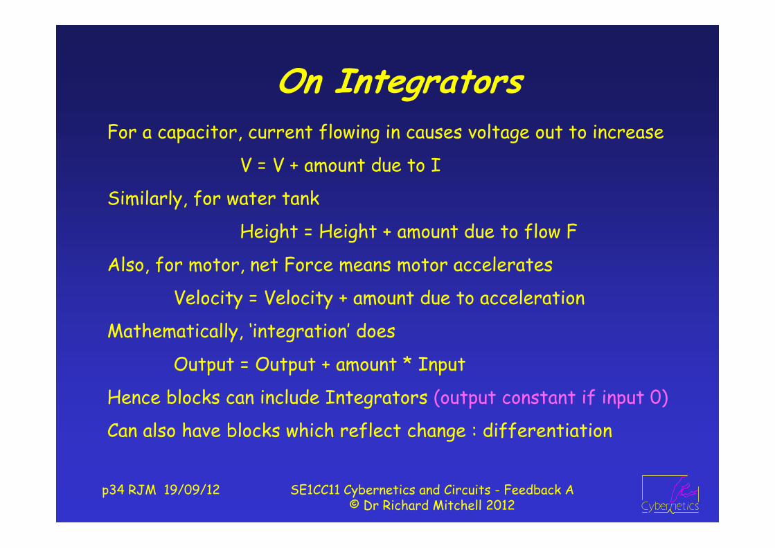
For a capacitor, current flowing in causes voltage out to increase
V = V + amount due to I
Similarly, for water tank
Height = Height + amount due to flow F
Also, for motor, net Force means motor accelerates
Velocity = Velocity + amount due to acceleration
Mathematically, ‘integration’ does
Output = Output + amount * Input
Hence blocks can include Integrators (output constant if input 0)
Can also have blocks which reflect change : differentiation
Examples
p35 RJM 19/09/12 SE1CC11 Cybernetics and Circuits - Feedback A© Dr Richard Mitchell 2012
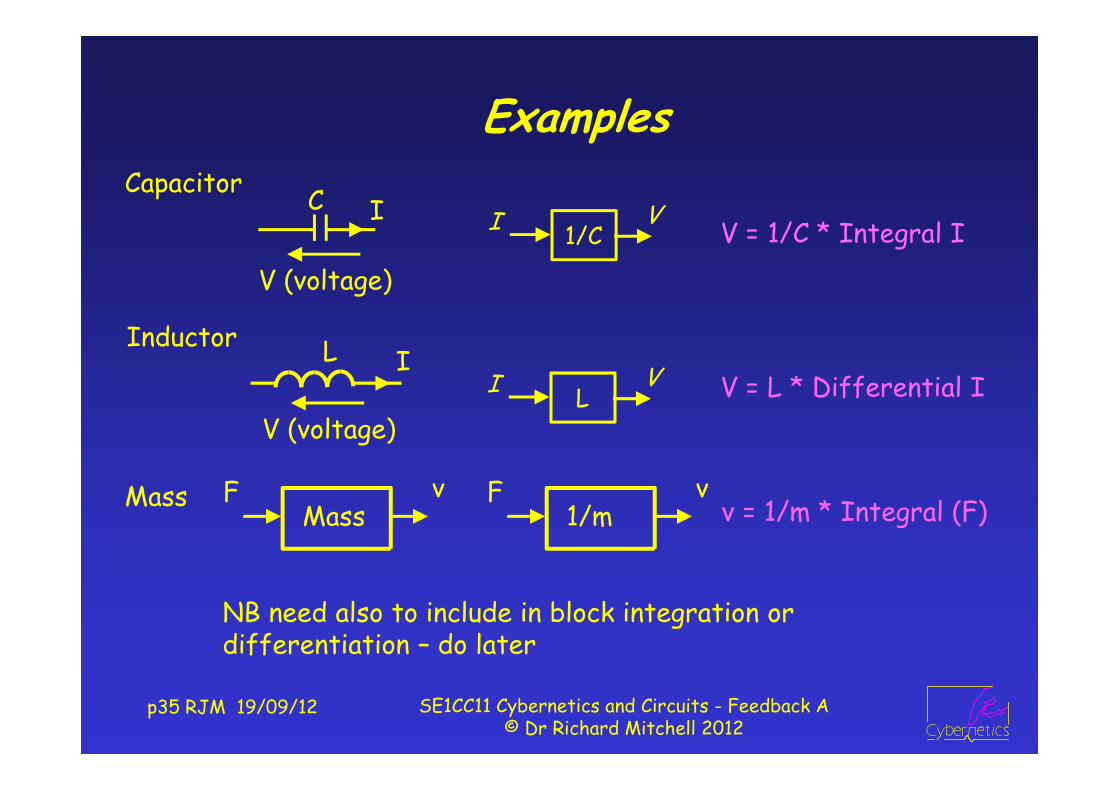
V (voltage)
V = 1/C * Integral II V1/C
Capacitor
V (voltage)V = L * Differential I
InductorI V
L
Mass F1/m
vv = 1/m * Integral (F)
FMass
v
NB need also to include in block integration or differentiation – do later

Analogous Components and Signals
p36 RJM 19/09/12 SE1CC11 Cybernetics and Circuits - Feedback A© Dr Richard Mitchell 2012
Used to model mechanical system with electrical one
Force equiv to Voltage Velocity equiv to Current
NB Position is Integral of velocity and acceleration differential of v
Damper = Resistor Spring = Capacitor Mass = Inductor
V (voltage)V = I * R
F = v * f
V (voltage)V = Integral I * 1/C
F = Differential v * 1/m
V (voltage)
V = Differential I * Lposition
Force
F = Integral v * k

p37 RJM 19/09/12 SE1CC11 Cybernetics and Circuits - Feedback A© Dr Richard Mitchell 2012
SummaryThus we have seen different types of system, some designed for
feedback, some with inherent feedback.
We have seen systems with negative and positive feedback.
We have seen three different but analogous systems.
We have looked at transfer functions of blocks
We have then said we can develop a model by sorting out the components and then combining. But how to combine?
Next week we will see how that can be done, for a control system.
We shall see that for a control system output may not equal input, but can be close …
Before next week try following Exercise

p38 RJM 19/09/12 SE1CC11 Cybernetics and Circuits - Feedback A© Dr Richard Mitchell 2012
Lecture 2 After Class Exercise
For this motor, you are to find steady state velocity v, as follows:
a)
b)
c)
F = 2 * 5 = 10N
F - X = 0, so X = 10
0.2 * v = 10, so v = 50 m/s
Go to Blackboard , module SE1CC11, find associated quiz and answer
vArmature
TF = 5
Net Force = F - X
Mass
FrictionTF = 0.2
Vin = 2V F
Frictional force = X
Given Vin and TF of armature, what is F?
What is X, when v at steady state?
Hence what is v then?
p39 RJM 19/09/12 SE1CC11 Cybernetics and Circuits - Feedback A© Dr Richard Mitchell 2012
3 : Analyzing Feedback Systems
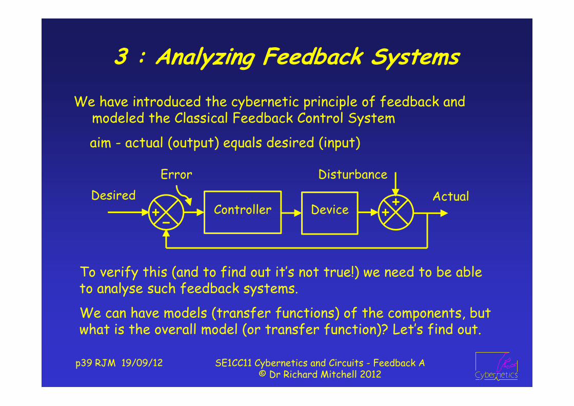
We have introduced the cybernetic principle of feedback and modeled the Classical Feedback Control System
aim - actual (output) equals desired (input)
To verify this (and to find out it’s not true!) we need to be able to analyse such feedback systems.
We can have models (transfer functions) of the components, but what is the overall model (or transfer function)? Let’s find out.
Desired Actual
Disturbance
Controller
Error
Device
p40 RJM 19/09/12 SE1CC11 Cybernetics and Circuits - Feedback A© Dr Richard Mitchell 2012
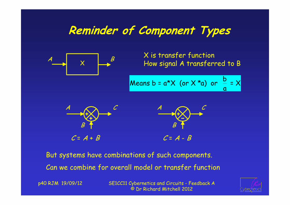
Reminder of Component Types
bMeans b = a*X (or X *a) or = Xa
BA X
A
B
CA
B
C
C = A - BC = A + B
X is transfer functionHow signal A transferred to B
But systems have combinations of such components.
Can we combine for overall model or transfer function
p41 RJM 19/09/12 SE1CC11 Cybernetics and Circuits - Feedback A© Dr Richard Mitchell 2012
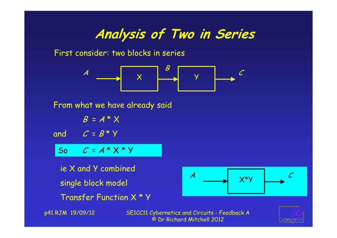
Analysis of Two in SeriesFirst consider: two blocks in series
From what we have already said
B = A * X
and C = B * Y
ie X and Y combined
single block model
Transfer Function X * Y
So C = A * X * Y
A BX CY
A CX*Y
p42 RJM 19/09/12 SE1CC11 Cybernetics and Circuits - Feedback A© Dr Richard Mitchell 2012
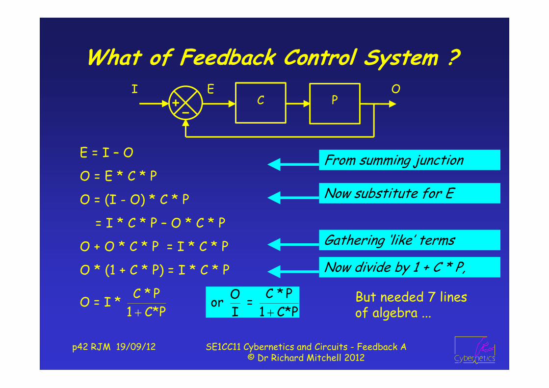
What of Feedback Control System ?
E = I – O
O = E * C * P
O = (I - O) * C * P
= I * C * P – O * C * P
O + O * C * P = I * C * P
O * (1 + C * P) = I * C * P
But needed 7 lines of algebra ...
C * PO = I * 1 C*P
C * PO or = I 1 C*P
From summing junction
Now substitute for E
Gathering ‘like’ terms
Now divide by 1 + C * P,
I OC
EP

p43 RJM 19/09/12 SE1CC11 Cybernetics and Circuits - Feedback A© Dr Richard Mitchell 2012
Better : Forward over 1 Minus Loop Rule
Forward transfer function, I to O,
ignore (0) feedback signals: C * P
Loop transfer function, ignore (set to 0) signals entering loop
E to E (or O to O) LTF = - C * P
(as I = 0, so O to E is -1)
O Forward C*P C*PThus, = = = I 1-Loop 1-- C*P 1 C*P
I OC
EP
I OCE P
I OCE P
‘closed loop transfer function’

p44 RJM 19/09/12 SE1CC11 Cybernetics and Circuits - Feedback A© Dr Richard Mitchell 2012
What about Disturbances?
Two + in second summing junction, so O = output of P + D
O Forward = = D 1-Loop
Thus
1 1 = 1--C*P 1 C*P
OD
IC
EP
OD
CE
P-1If assume I = 0,
Redraw as
Forward = 1; Loop same, so -CP

Complete Response
p45 RJM 19/09/12 SE1CC11 Cybernetics and Circuits - Feedback A© Dr Richard Mitchell 2012
This is the principle of superposition (used in circuits also), so
C*P 1O = * I * D
1 C*P 1 C*P
In effect, we assumed D = 0 and found
C*P C*PO = which is equivalent to O = * I I 1 C*P 1 C*P
When assumed I = 0, found O 1 1 = i.e. O = * D D 1 C*P 1 C*P
In general, I and D wont be 0, so can find O in terms of I and D by adding O when D = 0, to O when I = 0,

p46 RJM 19/09/12 SE1CC11 Cybernetics and Circuits - Feedback A© Dr Richard Mitchell 2012
Let’s Put Some Numbers In
C * P OWe have, O = * I Is O = I? i.e. is = 1?
1 C*P I
Answer NO, as 1+C*P ≠ C*P, but can be close
Let’s try with different values of C and P
If C = 5 & P = 2, O/I = 10/11 = 0.909
If C= 50 & P = 2, O/I = 100/101 = 0.9901
If C = 500 & P = 2, O/I = 1000/1001 = 0.999
Thus if High Loop Gain: O I
poornot badok?
I OC
EP

p47 RJM 19/09/12 SE1CC11 Cybernetics and Circuits - Feedback A© Dr Richard Mitchell 2012
What If P Changes?In practice, parameters of a model can change gradually
Resistor warms when current through it : resistance changes
Suppose P changes by 10%, from 2 to 2.2
If C = 5, O/I = 11/12 = 0.9167 0.84% change
[ When P was 2, O/I = 0.909:
% change = 100 * (0.9167-0.909) / 0.909 = 0.84]
If C = 50, O/I = 110/111 = 0.991 0.09% change
If C = 500, O/I = 1100/1101 = 0.999 0.009% change
High gain: O largely unaffected by change in P

p48 RJM 19/09/12 SE1CC11 Cybernetics and Circuits - Feedback A© Dr Richard Mitchell 2012
What about effect of Disturbances
1We've got: O = * D1 C*P
Is it good enough?
If C = 5 & P = 2, O/D = 1/11 = 0.0909
If C= 50 & P = 2, O/D = 1/101 = 0.009901
If C = 500 & P = 2, O/D = 1/1001 = 0.000999
Thus, high gain implies D has little effect on O.
Thus it is advantageous for the value C*P to be high.
We want: O = 0 * D
poornot badok?
p49 RJM 19/09/12 SE1CC11 Cybernetics and Circuits - Feedback A© Dr Richard Mitchell 2012
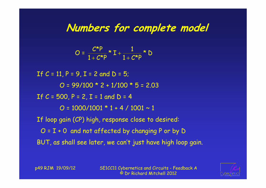
Numbers for complete model
If C = 11, P = 9, I = 2 and D = 5;
O = 99/100 * 2 + 1/100 * 5 = 2.03
If C = 500, P = 2, I = 1 and D = 4
O = 1000/1001 * 1 + 4 / 1001 ~ 1
If loop gain (CP) high, response close to desired:
O = I + 0 and not affected by changing P or by D
BUT, as shall see later, we can’t just have high loop gain.
C*P 1O = * I * D
1 C*P 1 C*P

p50 RJM 19/09/12 SE1CC11 Cybernetics and Circuits - Feedback A© Dr Richard Mitchell 2012
Lecture 3 In Class Exercise
a) Find 1 minus Loop
b) Find O/I assuming D = 0
c) Find O/D assuming I = 0
d) Evaluate O if I = 10 and D = -5
e) Find O/I if P changed to 40
Suppose
C = 27
P = 37
OD
IC
EP

p51 RJM 19/09/12 SE1CC11 Cybernetics and Circuits - Feedback A© Dr Richard Mitchell 2012
Feedback Not Just for Control
Note + sign in ‘summer’. Control system if A = C * P, = -1!
ForwardIgnoring D, using we get, 1-Loop
Or do by: O = A * X, X = I + * O, O = A*I + A* O
So O*(1-A*) = A*I i.e. same result!
So more General Feedback System
Control Engineers want O = I, Audio Engineers O = I * G
O A = I 1 A
OD
IA
X
F

p52 RJM 19/09/12 SE1CC11 Cybernetics and Circuits - Feedback A© Dr Richard Mitchell 2012
Analysis – and when Feedback Good
e.g. if A = -5000, = 0.2, A = -1000, 1- A = 1001, ~ - A
O = -5 * I again -1/β and independent of A
Suppose A >> 1 {much greater than 1} ‘negligibly large’
O A A 1 = = I 1 A -A
e.g. if A = -5000, = -0.2, A = 1000, 1-A = -999 ~ -A
1So O = * I = 5 * I (independent of A)
Also works if A << -1, (large and negative)
A 1O * I = * I
-A
Feedback good if modulus of Loop Gain, |A|, large
{ modulus means size, ignore sign: | 5 | = 5 |-5| = 5 }

p53 RJM 19/09/12 SE1CC11 Cybernetics and Circuits - Feedback A© Dr Richard Mitchell 2012
Disturbance Response
If A << -1, O = (small positive number) * D
If A >> 1, O = (small negative number) * D
So, if feedback good (|A | large), O ~ 0
O ForwardSet I = 0, then = = D 1 Loop
OD
IA
X
F
p54 RJM 19/09/12 SE1CC11 Cybernetics and Circuits - Feedback A© Dr Richard Mitchell 2012
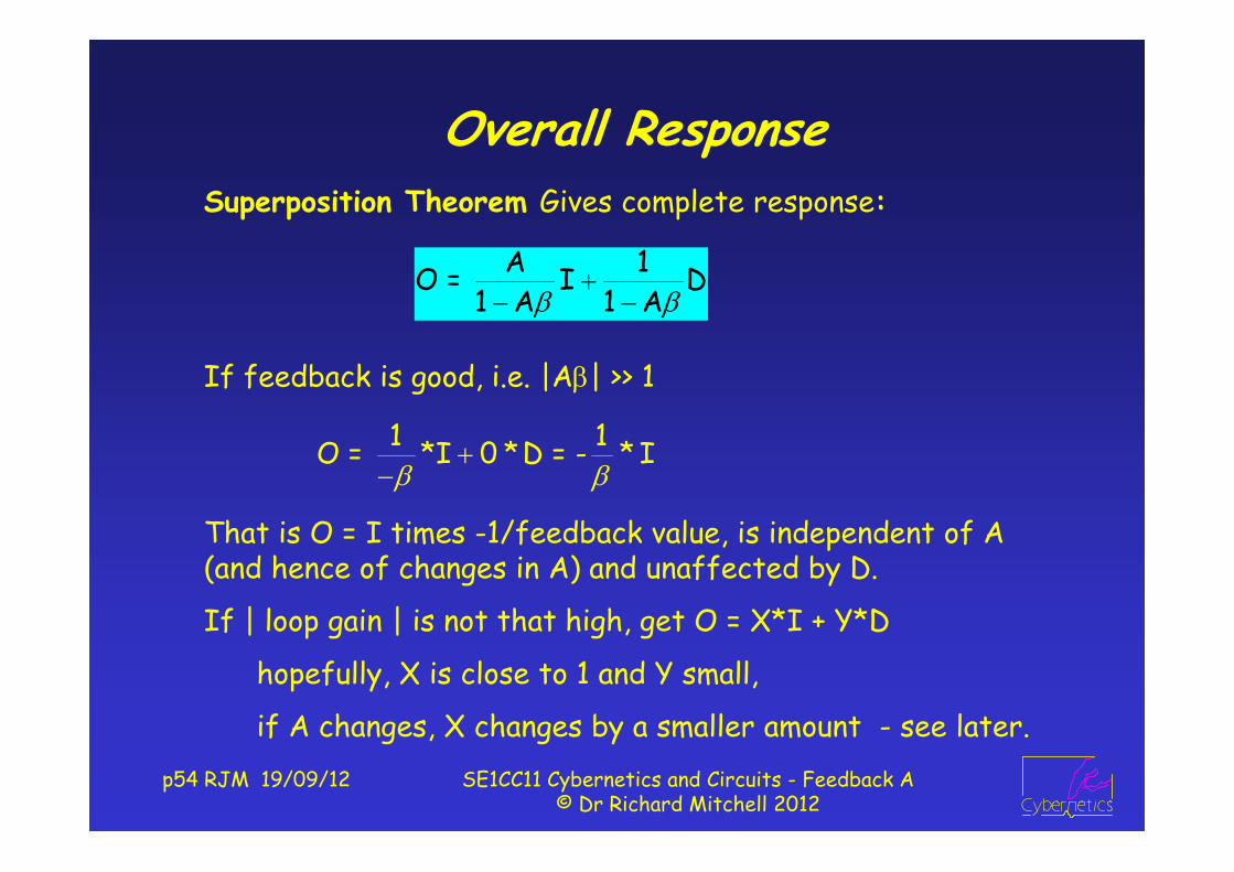
Overall ResponseSuperposition Theorem Gives complete response:
1 1 O = *I 0 *D = - * I
If feedback is good, i.e. |A| >> 1
That is O = I times -1/feedback value, is independent of A (and hence of changes in A) and unaffected by D.
If | loop gain | is not that high, get O = X*I + Y*D
hopefully, X is close to 1 and Y small,
if A changes, X changes by a smaller amount - see later.
A 1O = I D
1 A 1 A

p55 RJM 19/09/12 SE1CC11 Cybernetics and Circuits - Feedback A© Dr Richard Mitchell 2012
Example – A = 100, = 0.21 1-A = 1-21 = -20
If I = 2, and D = 0, O = -5*2 = -10
Check: F = -2.1, so X = 2+-2.1 = -0.1; O = 100*-0.1+0 = -10If I = 0 and D = 1, O = -0.05 * 1 = -0.05.
Check: F = -0.0105 = X, so O = -0.0105*100+1 = -0.05
If I = 2 and D = 3; O = -5*2 + 3*-0.05 = -10.15
Check: F = -2.1315; X = -0.1315; O = -13.15+3 = -10.15
O A 100 = = = 5I 1-A 20
O 1 1 = = = 0.05D 1-A 20
OD
IA
X
F

Real System – in Electronics
p56 RJM 19/09/12 SE1CC11 Cybernetics and Circuits - Feedback A© Dr Richard Mitchell 2012
Operational Amplifier
VOA
Vi-
Vi+
Potential Divider
2 o
1 2
R= VR R
21 2
RR + R
VO Vm
Vo = A * ( Vi+ - Vi
- )
A very big, ~105,

p57 RJM 19/09/12 SE1CC11 Cybernetics and Circuits - Feedback A© Dr Richard Mitchell 2012
Combine asIn use, put feedback round op-amp :Vi
- found by potential divider = VI
Suppose R1 = 9kΩ and R2 = 1kΩAssume A very big, 105
oI
V A = V 1 A*0.1
A = 10A*0.1
Block Diagram for complete analysis
VOVI A
Vi-
0.1
o oV *1k V = 9k + 1k 10
1k = = 0.19k + 1k
5
o4I
V 10 In fact = = 9.999V 1 10
p58 RJM 19/09/12 SE1CC11 Cybernetics and Circuits - Feedback A© Dr Richard Mitchell 2012
SummaryWe have analysed simple feedback systems :
used forward over one minus loop for closed loop TF
We have seen benefit of high loop gain
We have seen practical (op-amp) circuits
We will extend the analysis next week
And consider positive and negative feedback
Before next week do following Exercise on Blackboard

p59 RJM 19/09/12 SE1CC11 Cybernetics and Circuits - Feedback A© Dr Richard Mitchell 2012
Lecture 3 After Class Exercise
Suppose A = 200, β = -0.2
a) Find O/I if D = 0
b) Find O/D if I = 0
c) Find %change in O/I if
A changes by 10% to 220
a) O/I = 200/(1+40) = 4.878
b) O/D = 1/41 = 0.024
c) O/I = 220/1+44 = 4.889
%ch = 100 * (4.889 – 4.878) / 4.878 = 0.226%
OD
IA
X
F

p60 RJM 19/09/12 SE1CC11 Cybernetics and Circuits - Feedback A© Dr Richard Mitchell 2012
4 : More Feedback Systems AnalysisWe extend our analysis; show how computers can be used;
and tackle the question of positive and negative feedback.
For this feedback control system: use forward/1-loopO C*PIf D = 0, = I 1+C*P
O 1If I = 0, = D 1+C*P
C * P 1Overall, O = * I + * D1 + C*P 1 + C*P
If C*P big, O ~ 1*I + 0*D - what control engineers want
OD
IC
EP

If more than one loop ...
p61 RJM 19/09/12 SE1CC11 Cybernetics and Circuits - Feedback A© Dr Richard Mitchell 2012
Better control if feedback position and velocity :
TF = Forward over 1 minus sum of loops (-CP and –PV)O C*P C*PIf D = 0, = = I 1--C*P--P*V 1+C*P+P*V
O 1If I = 0, = D 1+C*P+P*V
Ok in this configuration – will return to multi loops later
OD
I CE P
V
p62 RJM 19/09/12 SE1CC11 Cybernetics and Circuits - Feedback A© Dr Richard Mitchell 2012
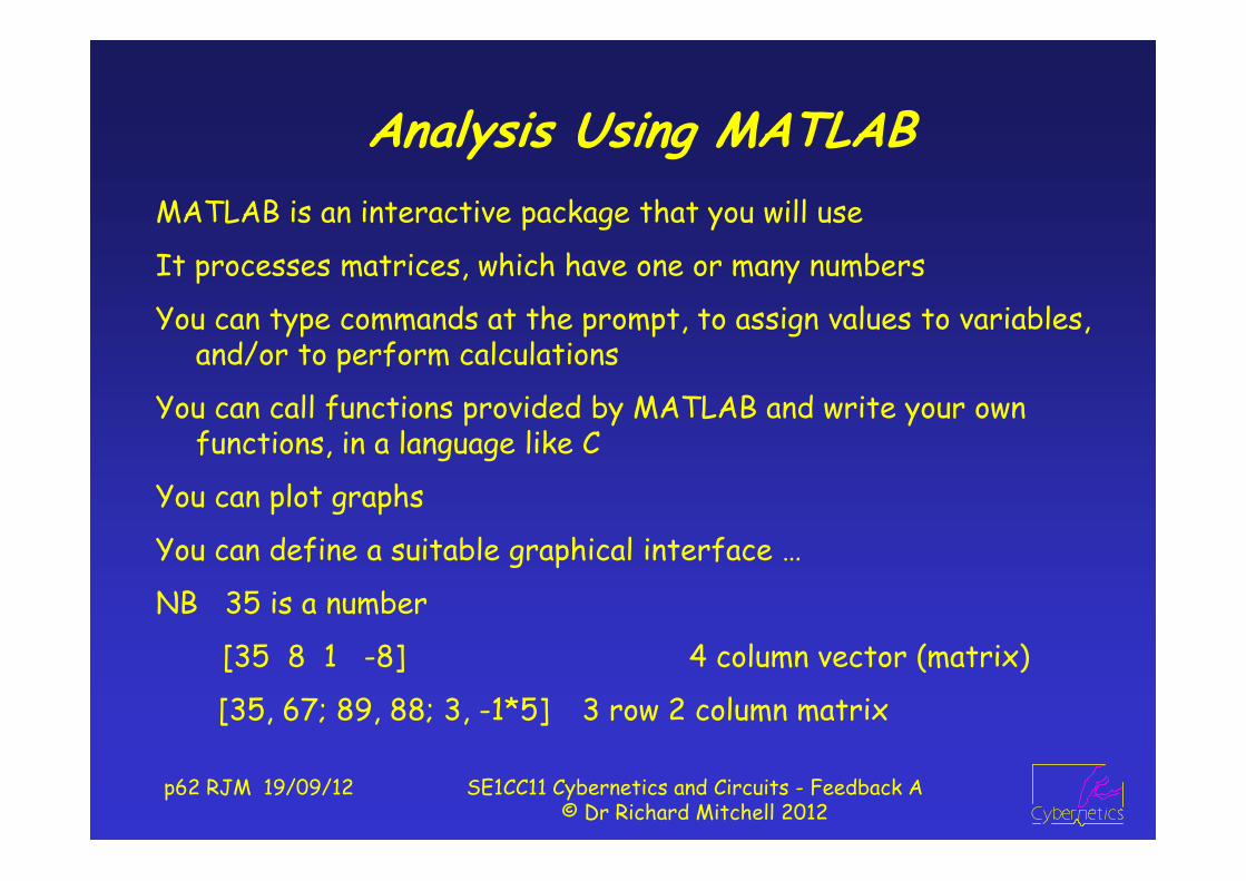
Analysis Using MATLABMATLAB is an interactive package that you will use
It processes matrices, which have one or many numbers
You can type commands at the prompt, to assign values to variables, and/or to perform calculations
You can call functions provided by MATLAB and write your own functions, in a language like C
You can plot graphs
You can define a suitable graphical interface …
NB 35 is a number
[35 8 1 -8] 4 column vector (matrix)
[35, 67; 89, 88; 3, -1*5] 3 row 2 column matrix
p63 RJM 19/09/12 SE1CC11 Cybernetics and Circuits - Feedback A© Dr Richard Mitchell 2012
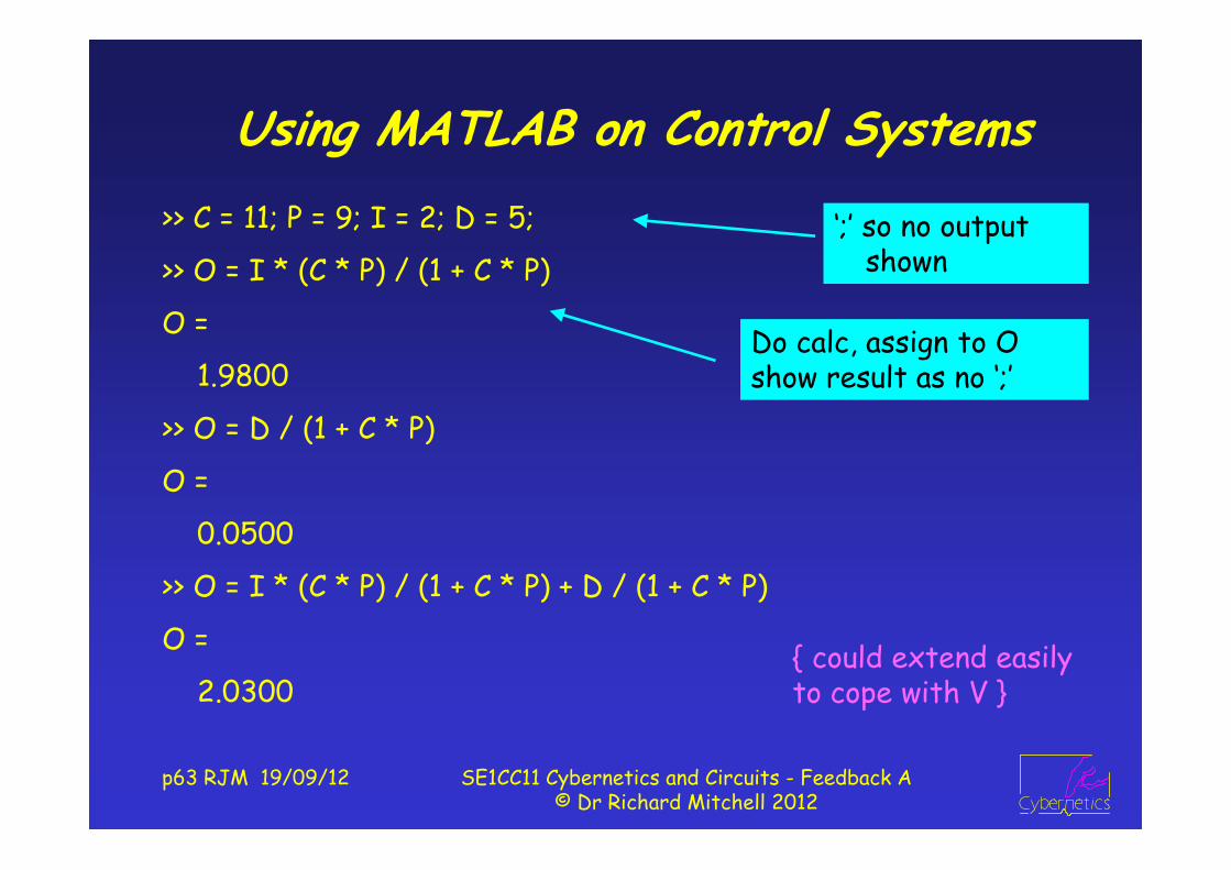
Using MATLAB on Control Systems>> C = 11; P = 9; I = 2; D = 5;
>> O = I * (C * P) / (1 + C * P)
O =
1.9800
>> O = D / (1 + C * P)
O =
0.0500
>> O = I * (C * P) / (1 + C * P) + D / (1 + C * P)
O =
2.0300
‘;’ so no output shown
Do calc, assign to O show result as no ‘;’
{ could extend easily to cope with V }

p64 RJM 19/09/12 SE1CC11 Cybernetics and Circuits - Feedback A© Dr Richard Mitchell 2012
Or to see effect of change in P>> C = 50; P = 2; Pnew = P * (1.1);>> OoverI = C * P / (1 + C * P)OoverI =
0.9901>> OoverD = 1 / (1 + C * P)OoverD =
0.0099>> OoverInew = C * Pnew / (1 + C * Pnew)OoverInew =
0.9910>> PCchange = 100 * (OoverInew - OoverI) / OoverIPCchange =
0.0901
Set Values
Calc O/I
Calc O/D
Calc O/I new P
Calc % change in O/I

p65 RJM 19/09/12 SE1CC11 Cybernetics and Circuits - Feedback A© Dr Richard Mitchell 2012
Can Write MATLAB Functionfunction FBSys (C, P, pc); % store in file fbsys.m% FBSYS (C, P, pc)% Analyse feedback system with gains C and P% noting effect when P change by pc%, % Dr Richard Mitchell 12/7/05den = (1 + C * P); % calculate valuesOoverI = C * P / den;OoverD = 1 / den;Pa = P + P * pc/100; % find new POaoverI = C * Pa / (1 + C * Pa); % and now output them[OoverI, OoverD, OaoverI, 100*(OaoverI-OoverI)/OoverI]>> fbsys(50, 2, 10)
0.9901 0.0099 0.9910 0.0901

p66 RJM 19/09/12 SE1CC11 Cybernetics and Circuits - Feedback A© Dr Richard Mitchell 2012
More General Feedback System
If D = 0, If I = 0,
Overall
If A*β big, O ~ -I/β + 0*D - what other engineers want
If A changes and A*β still big, O unaffected
O A = I 1 A
O 1 = D 1 A
A 1O = I D
1 A 1 A
OD
IA
X
F

p67 RJM 19/09/12 SE1CC11 Cybernetics and Circuits - Feedback A© Dr Richard Mitchell 2012
MATLAB Analysis of Aβ System>>A=200; b=-0.1;>> OoverI=A/(1-A*b)OoverI =
9.5238>> OoverD=1/(1-A*b)OoverD =
0.0476>> Anew = A*1.1; OoverInew=Anew/(1-Anew*b)OoverInew =
9.5652>> PCchange=100*(OoverInew-OoverI)/OoverIPCchange=
0.4348
Set Values
Calc O/I
Calc O/D
Calc O/I new P
Calc % change in O/I

p68 RJM 19/09/12 SE1CC11 Cybernetics and Circuits - Feedback A© Dr Richard Mitchell 2012
Lecture 4 In Class ExerciseWrite MatLab function to calculate transfer functions so as to find and print percentage change in closed loop gain when A changes by pc%
function FBSys (A, b, pc);% FBSYS (A, b, pc)% For system A in forward, b in feedback paths% find change in gain when A changes by pc%
OoverI = A/(1-A*b);Anew = A + A*pc/100; OoverInew = Anew/(1-Anew*b)PCchange = 100*(OoverInew-OoverI)/OoverI

p69 RJM 19/09/12 SE1CC11 Cybernetics and Circuits - Feedback A© Dr Richard Mitchell 2012
Positive/Negative FeedbackWe will correct erroneous definitions / claims often made.
Wrong to say negative feedback because - sign in ‘summer’
(Changing sign of has same effect as changing + to -)
The important point is to have both
a) claims for what negative feedback is
b) a consistent definition for negative feedback
To that end the correct view is that Negative Feedback
a) reduces effects on output of disturbances
reduces effects on output of parameter changes
b) if |closed loop gain| < |open loop gain|
We need to quantify this. NB | x | means size : ignore sign

p70 RJM 19/09/12 SE1CC11 Cybernetics and Circuits - Feedback A© Dr Richard Mitchell 2012
Negative Feedback (Harold Black 1930s)Forward Path (Open Loop) Gain = AFeedback Path Gain = Loop Gain = A
= < 1- 1- A A AA A
Closed Loop Gain =
1AA
Negative Feedback | closed loop gain | < | open loop gain |
OD
IA
X
F
1i.e. 1 or 1 1- 1-
AA
eg A = 10, = 0.05
A = 10, = 0.5
A = 10, = -0.5
|1 - A | = | 1–0.5 | = 0.5 Pos|1 - A | = | 1 – 5 | = 4 Neg|1 - A | = | 1 – -5 | = 6 Neg
p71 RJM 19/09/12 SE1CC11 Cybernetics and Circuits - Feedback A© Dr Richard Mitchell 2012
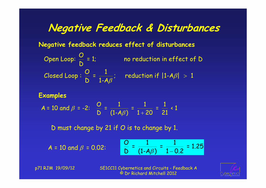
Negative Feedback & DisturbancesNegative feedback reduces effect of disturbances
OOpen Loop: = 1; no reduction in effect of DD
O 1Closed Loop : = ; reduction if |1-A | 1D 1-A
O 1 1 1A = 10 and = -2: = = = < 1D (1-A ) 1 20 21
Examples
D must change by 21 if O is to change by 1.
A = 10 and = 0.02: O 1 1 = = = 1.25D (1-A ) 1 0.2

p72 RJM 19/09/12 SE1CC11 Cybernetics and Circuits - Feedback A© Dr Richard Mitchell 2012
… and Changes in Parameters
A(1 )-ARelative change in A: open loop = = A
It can be shown (see next slide: closed loop =
if you are interested) that 1-A
Negative Feedback reduces effects of changes in paras
Let A change by a small proportion: call it : A := A(1 + )
Feedback reduces the effect of change in A if |1-A | > 1.
Let A = 10, δ = 0.1 (A change by 10% to 11) and = 1;
Open loop change = 0.1; Closed Loop = 0.1/-9 = -0.0111
Check: when A = 10; O/I = 10/-9 = -1.1111
when A = 11; O/I = 11/-10 = -1.1; diff is -0.0111

p73 RJM 19/09/12 SE1CC11 Cybernetics and Circuits - Feedback A© Dr Richard Mitchell 2012
Interest Only: A → A(1 + )A(1 )Closed Loop Gain =
1-A(1 )
A(1 ) A1 1-A1-A(1 ) 1-A = 1A 1-A(1 )
1-A1 1-A 1-A(1 ) =
1-A(1 )1 A A 1 A A = =
1-(A A ) 1-A(1 )
new - oldRelative change = old
As 1, this approximates to , as stated earlier1-A
Can also do by differentiating closed loop TF w.r.t A
p74 RJM 19/09/12 SE1CC11 Cybernetics and Circuits - Feedback A© Dr Richard Mitchell 2012
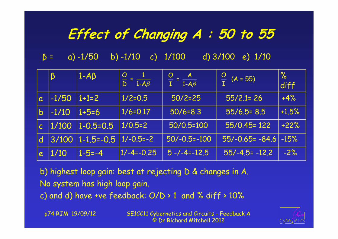
Effect of Changing A : 50 to 55
b) highest loop gain: best at rejecting D & changes in A.No system has high loop gain.c) and d) have +ve feedback: O/D > 1 and % diff > 10%
β = a) -1/50 b) -1/10 c) 1/100 d) 3/100 e) 1/10
β 1-Aβ % diff
a -1/50 1+1=2b -1/10 1+5=6c 1/100 1-0.5=0.5d 3/100 1-1.5=-0.5e 1/10 1-5=-4
O A = I 1-A
O 1 = D 1-A
O (A = 55)I
1/2=0.5 50/2=25 55/2.1= 26 +4%
1/6=0.17 50/6=8.3 55/6.5= 8.5 +1.5%
1/0.5=2 50/0.5=100 55/0.45= 122 +22%
1/-0.5=-2 50/-0.5=-100 55/-0.65= -84.6 -15%
1/-4=-0.25 5 -/-4=-12.5 55/-4.5= -12.2 -2%

p75 RJM 19/09/12 SE1CC11 Cybernetics and Circuits - Feedback A© Dr Richard Mitchell 2012
Graphs for b) : A = 50, β = -0.1
O 50 O 1Here = and = , soI 6 D 6
It can be useful to plot graphs of O vs I and O vs D
As straight lines … associated system is said to be linearGradient of O/D < 1 : system has negative feedback
Both straight lines thru 0,0O/I thruO = 50, I = 6
O/D thruO = 1, I = 6

p76 RJM 19/09/12 SE1CC11 Cybernetics and Circuits - Feedback A© Dr Richard Mitchell 2012
SummaryWe have analysed feedback system : A and CP
We have briefly noted multiple loops
We have an appropriate definition of negative feedback
We have shown that can plot graphs of O vs I and O vs D
These are straight lines … means systems are linear.
NB Principle of Superposition only true for linear systems
Next week we build on this …
and consider limits …
which make systems non-linear
Before next week do following exercise on blackboard

p77 RJM 19/09/12 SE1CC11 Cybernetics and Circuits - Feedback A© Dr Richard Mitchell 2012
Lecture 4 After Class Exercise a)Here, I = 2, A = 10.Find O and state whether positive feedback if:
a) = -1 b) = +1c) = -0.02 d) = +0.02
d) O = 2 * 10 / (1-0.2) = 25 +ve fb
c) O = 2 * 10 / (1+0.2) = 16.667 -ve fb
b) O = 2 * 10 / (1-10) = -2.222 -ve fb
a) O = 2 * 10 / (1+10) = 1.818 -ve fb
OIA
X
F

p78 RJM 19/09/12 SE1CC11 Cybernetics and Circuits - Feedback A© Dr Richard Mitchell 2012
5 : Feedback Systems and Limits
Recall last week’s system with A = 50, β = -0.1
1 - A β = 1+5 = 6
O 50 O 1 = and = I 6 D 6
We consider effects on feedback systems of (practical) limits –system signals cannot be infinite.
Straight line graphs –system is linear
|1 - A β| > 1 : -ve fb
I OD
A
X
F

p79 RJM 19/09/12 SE1CC11 Cybernetics and Circuits - Feedback A© Dr Richard Mitchell 2012
LimitsO/I graph implies that as I increases, so O increases
Not true in practical systems
e.g. output of a component can’t exceed its power supply
The output has limits; and we can incorporate them.
If -L ≤ In ≤ L, Out = In;
if In < -L, Out = -L; if In > L, Out = L
Below are shown limits graphically and as a block diagram
In
Out+L
-L
Limit Block
In Out+L
p80 RJM 19/09/12 SE1CC11 Cybernetics and Circuits - Feedback A© Dr Richard Mitchell 2012
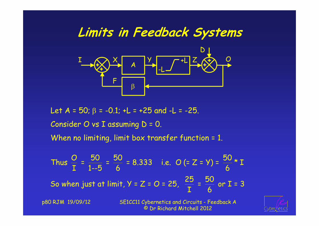
Limits in Feedback Systems
Let A = 50; = -0.1; +L = +25 and -L = -25.
Consider O vs I assuming D = 0.
When no limiting, limit box transfer function = 1.
O 50 50 50Thus = = = 8.333 i.e. O (= Z = Y) = * II 1--5 6 6
25 50So when just at limit, Y = Z = O = 25, = or I = 3 I 6
OD
IA
X
F-L
+LY Z

p81 RJM 19/09/12 SE1CC11 Cybernetics and Circuits - Feedback A© Dr Richard Mitchell 2012
What happens when pass Limit?
If I increases, X and Y increase, but Z and O stay at 25
A = 50
= -0.1
L = 25
At limit
I = 3, O = 25
Use same argument for limit -25;
or say ‘by symmetry’ when I = -3, O = -25,
if I more –ve O stay -25
Hence (non linear) graph of OvI
OD
IA
X
F-L
+LY Z
p82 RJM 19/09/12 SE1CC11 Cybernetics and Circuits - Feedback A© Dr Richard Mitchell 2012
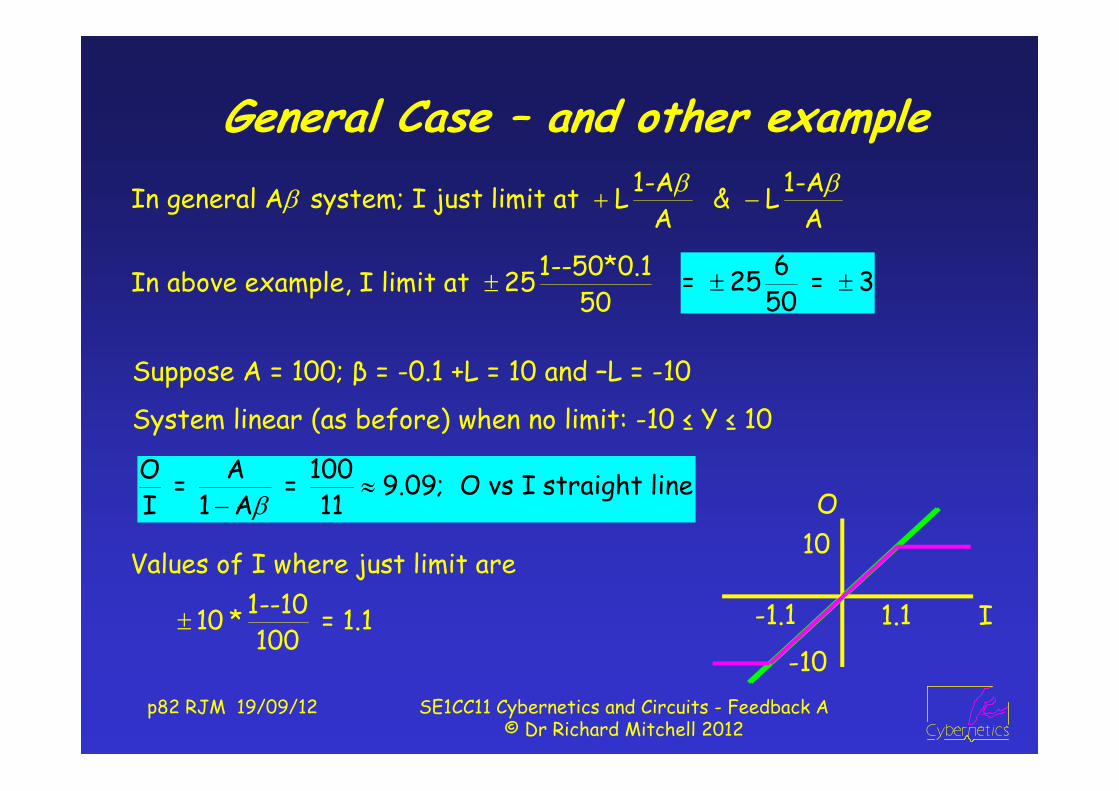
General Case – and other example1-A 1-AIn general A system; I just limit at L & L
A A
1--50*0.1In above example, I limit at 2550
6= 25 = 3
50
Suppose A = 100; β = -0.1 +L = 10 and –L = -10
System linear (as before) when no limit: -10 ≤ Y ≤ 10
O A 100 = = 9.09; O vs I straight lineI 1 A 11
Values of I where just limit are1--10 10 * = 1.1100
p83 RJM 19/09/12 SE1CC11 Cybernetics and Circuits - Feedback A© Dr Richard Mitchell 2012
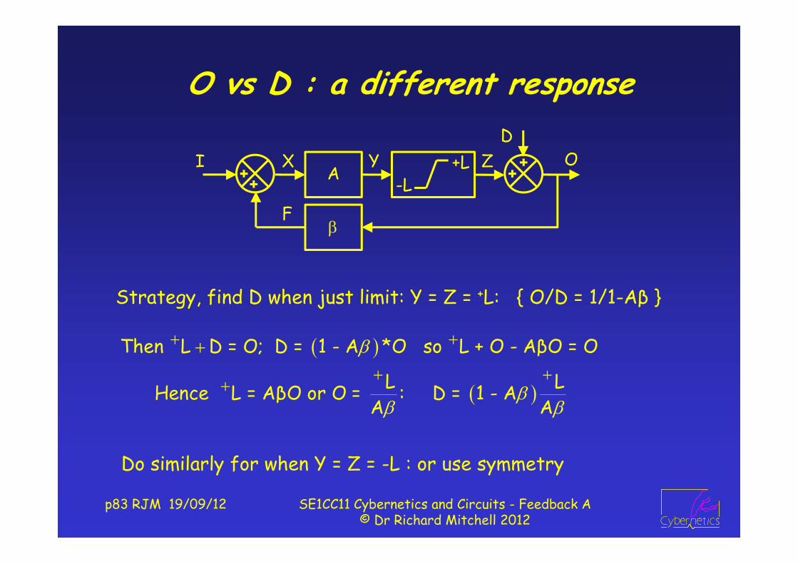
O vs D : a different response
Do similarly for when Y = Z = -L : or use symmetry
Strategy, find D when just limit: Y = Z = +L: { O/D = 1/1-Aβ }
Then L D = O; D = 1 - A *O so L + O - AβO = O
L L Hence L = AβO or O = : D = 1 - A A A
OD
IA
X
F-L
+LY Z

p84 RJM 19/09/12 SE1CC11 Cybernetics and Circuits - Feedback A© Dr Richard Mitchell 2012
So, when A = 100; = -0.1
If D ↓ 1 to -12, O = -12 + 10 = -2. ie O ↓ 1 : O/D now 1
By symmetry, Y = Z = -10 when D = 11;
If D then ↑ 1 to 12, O up by 1
If -11 ≤ D ≤ 11, effects of D on O
reduced by feedback,
otherwise no feedback, no reduction.
When just about to limit (remember A = 100*-0.1 = -10)
L 10 O = = = -1; D = 1-A * 1 = -11; A -10
O 1 1If -10 Y 10, response as usual: = = D 1 A 11
When just about to limit (remember A = 100*-0.1 = -10)
L 10 O = = = -1; D = 1-A * 1 = -11; A -10

p85 RJM 19/09/12 SE1CC11 Cybernetics and Circuits - Feedback A© Dr Richard Mitchell 2012
Lecture 5 In Class ExerciseA = 1000 = -1/5+L = 20-L = -20
Calc O & D at L = -20 to label the graph
O = L/(A) = +20/(1000 * -0.2)= -20/200 = -0.1
D = O*(1-A )= -0.1 * 201 = -20.1
Click to Run Limits Prog
OD
IA
X
F-L
+LY Z

p86 RJM 19/09/12 SE1CC11 Cybernetics and Circuits - Feedback A© Dr Richard Mitchell 2012
Limits and Hole in the Ozone LayerThe ozone layer is a feedback system
Must be (according to Gaia) so correct amount of u.v. getting to Earth’s surface:
Too much u.v → cancer; too little → rickets
If ozone layer too thin, u.v. gets through : finds oxygen; turns it to ozone, thickens ozone layer: feedback!
Worked til too much CFC – which destroys ozone
CFCs are disturbances, and normally feedback reduces effects of CFCs
But when too much, system not cope as then has no feedback to reduce any extra disturbance

p87 RJM 19/09/12 SE1CC11 Cybernetics and Circuits - Feedback A© Dr Richard Mitchell 2012
What of Limits & Positive Loop Gain
Suppose O = 10 and I = 1; F = 1, X = 2, Y = 200, so O = 10
If I reduced to -0.9: X = 0.1, Y = 10, O = 10 No change.
If I now -0.91: X = -0.91+1 = 0.09, Y = 9, O = 9
Then X = -0.01, Y = -1, O = -1
And then X = -1.01, Y = -101, O = -10
Very rapidly, O flipped +10 to -10 when I passed -0.9.
We will now see different response when loop gain > 0 …
OI100
0.1
X
F
-10+10Y

p88 RJM 19/09/12 SE1CC11 Cybernetics and Circuits - Feedback A© Dr Richard Mitchell 2012
Limits and Positive Loop Gain
This change from +10 to -10 is represented graphically as
If I reduced now no change.
But if I increased to 0
X = -1, O = -10 still
Even if I upped to +0.9:
X = -0.1, O = -10, still, but..
I
O
-0.9
OI100
0.1
X
F
-10+10Y

p89 RJM 19/09/12 SE1CC11 Cybernetics and Circuits - Feedback A© Dr Richard Mitchell 2012
O stays at 10 until I again < -0.9.
O depends on I and on O!
Hysteresis: figure to right
How to Flip Back
Thus, when I exceeds 0.9, O flips back to + 10
If, however, I upped to 0.91,
X = I + O/10 = -0.09 O = 100 * X = -9
Then X = 0.01, O = 1; Then X = 1.01, Y = 101, O = 10
I
O
0.9
I
O
-0.9 0.9
p90 RJM 19/09/12 SE1CC11 Cybernetics and Circuits - Feedback A© Dr Richard Mitchell 2012
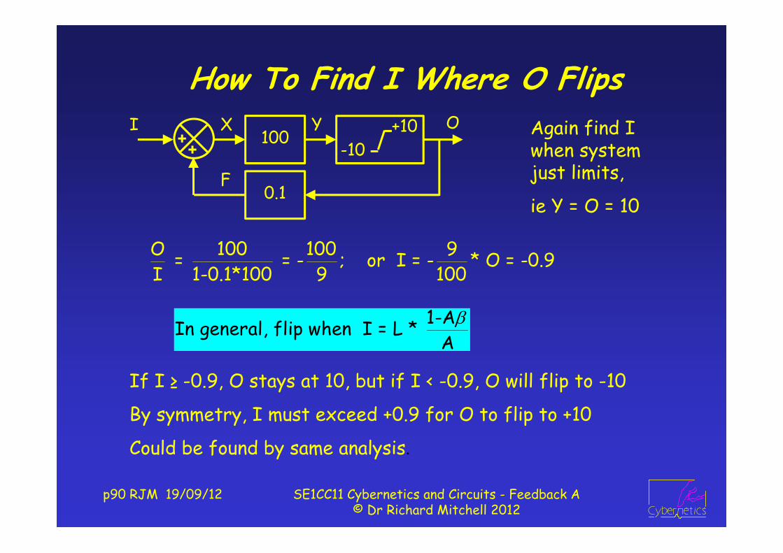
How To Find I Where O Flips
O 100 100 9 = = - ; or I = - * O = -0.9I 1-0.1*100 9 100
If I ≥ -0.9, O stays at 10, but if I < -0.9, O will flip to -10
By symmetry, I must exceed +0.9 for O to flip to +10
Could be found by same analysis.
Again find I when system just limits,
ie Y = O = 10
1-AIn general, flip when I = L * A
OI100
0.1
X
F
-10+10Y

p91 RJM 19/09/12 SE1CC11 Cybernetics and Circuits - Feedback A© Dr Richard Mitchell 2012
MATLAB Code to Plot Limitsfunction fblims (A, b, lim, whatplot); % plot limit systemOmAb = 1 - A*b; % 1 minus A * bIlim = lim * OmAb / A; % value of I when just limitingif A*b > 0 % +ve loop gain – plot hysteresis
plot([-Ilim-5, Ilim, Ilim, Ilim+5, -Ilim, -Ilim, -Ilim-5], ...[-lim, -lim, lim, lim, lim, -lim, -lim]);
elseif whatplot == 0 % -ve loop gain – plot O/Iplot ([-Ilim-5, -Ilim, Ilim, Ilim+5], [-lim, -lim, lim, lim]);
else % -ve loop, plot O/DOlim = lim / (A*b); % O when just limitsDlim = Olim * OmAb; % D when just limitsplot([-Dlim-5, -Dlim, Dlim, Dlim+5], [-Olim-5, -Olim, Olim, Olim + 5]);
end
p92 RJM 19/09/12 SE1CC11 Cybernetics and Circuits - Feedback A© Dr Richard Mitchell 2012
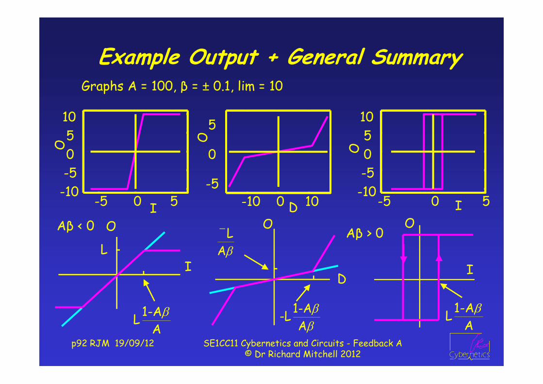
Example Output + General SummaryGraphs A = 100, β = ± 0.1, lim = 10
-5 0 5-10-505
10
I
O
-10 0 10-5
0
5
DO
-5 0 5-10-50510
I
O
1-ALA
LA
1-A-LA
Aβ < 0 Aβ > 0
1-ALA

p93 RJM 19/09/12 SE1CC11 Cybernetics and Circuits - Feedback A© Dr Richard Mitchell 2012
‘hysteresis’ loop input,
I = -C * ∫ O
I changes at rate -CO
As O > 0, I is integral of –ve constant, so I decreases
At time t, I = Flip - C*Lim*t
At t = 2*Flip / C*Lim, I = -Flip, O := -Lim
Input to ∫ C*Lim (>0), I increases constantly
At t = 4*Flip / C*Lim, I = +Flip, O := +Lim
I
Ot = 0, I = +Flip, O = +Lim
4*Flip / C*Lim
Application: Square Wave Generator
OI100
0.1
X-10
+10Y-C∫
To introduce dynamic systems – see simple use of integratorNB if input to integrator is constant, output changes at constant rate

p94 RJM 19/09/12 SE1CC11 Cybernetics and Circuits - Feedback A© Dr Richard Mitchell 2012
Summary
We have seen effect of limits on feedback systems
If negative loop gain, get different responses O/I O/D
For positive loop gain, get hysteresis
Saw how with integrator, could make square waves
Next term
We start to consider dynamic analysis
Where we will use integrators more
and (building on what you will learn in circuits), √-1
Before next week, try following exercise on blackboard
p95 RJM 19/09/12 SE1CC11 Cybernetics and Circuits - Feedback A© Dr Richard Mitchell 2012
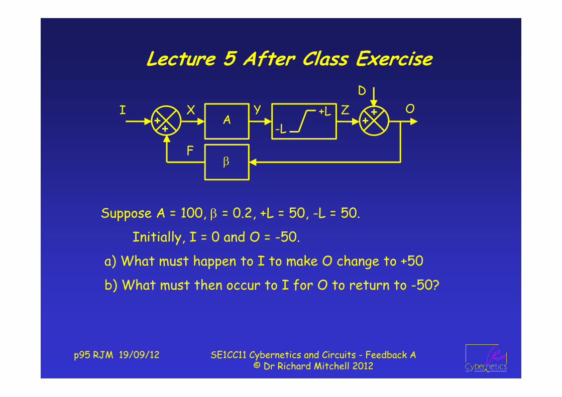
Lecture 5 After Class Exercise
Suppose A = 100, = 0.2, +L = 50, -L = 50.
Initially, I = 0 and O = -50.
a) What must happen to I to make O change to +50
b) What must then occur to I for O to return to -50?
OD
IA
X
F
-L+LY Z

p96 RJM 19/09/12 SE1CC11 Cybernetics and Circuits - Feedback A© Dr Richard Mitchell 2012
Answer : L5 After Class ExerciseO = -50. First find value of I such that O just not flip
So find case when O = Y = -50;
I flip = -Lim * (1 – A ) / A
= -50 * (1 – 100*0.2) / 100 = -50 * -19 / 100 = 9.5
Thus O will change to +50 when I exceeds 9.5
When O = Y = 50,
I flip = Lim * (1 – A ) / A
= 50 * (1 – 100*0.2) / 100 = 50 * -19 / 100 = -9.5
Thus O will change back to -50 when I is less than -9.5.
[Could have said -9.5 by symmetry argument]


