Download - CSC 211 Manual

CSC-211 Numerical Backup Protection Equipment
User’s Manual

CAUTION
1) This manual applies only to CSC-211.2) Please read the manual and the specification of the installation,
adjustment, testing, operation and maintenance carefully.3) To prevent damage to equipment, don’t plug-hot-plug any unit of the
equipment and touch the chips and components in printed circuit board.4) Please use the eligible testing equipments and devices to test and detect
the CSC-211 protection equipment.5) If any abnormality occurred in the equipment or unusual maintenance is
needed, please promptly contact with the agents or our service hotline.6) The operation password is: 8888.
WARNING1) During operation of electrical equipment, certain parts of this equipment are
under high voltage. Improper behavior could result in severe personal injuryor significant equipment damage.
2) Only qualified personnel should work on this equipment or in vicinity of theequipment. These persons must be familiar with warning & serviceprocedure described in this manual, as well as with safety regulations.
3) Prerequisites to proper & safety operation of the equipment are properstorage, setup, installation, operation & maintenance of the equipment.
4) In particular cases, the general rules & safety regulations according torelating standards (e.g. IEC, National standards or other Internationalstandards)for work with high voltage equipment must be observed.
COPYRIGHTAll rights reserved.

CONTENTS
1Features ........................................................................................................................................... 7
2Construction .................................................................................................................................... 8
3Protection functions ....................................................................................................................... 9
3.1HS/LS OC protection (For MODEL 1) ......................................................................................... 9
3.2HS/LS EF protection (For MODEL 1) ........................................................................................ 12
3.3INV OC/EF protection (For MODEL 1) ...................................................................................... 14
3.4Overload protection (For MODEL 1) ........................................................................................ 20
3.5UV&OV protection (For MODEL 1 , 1a and 2) .......................................................................... 20
3.6Thermal overload protection (For MODEL 1) .......................................................................... 23
3.7CBF protection (For MODEL 1) ................................................................................................. 24
3.8U/F&O/F protection (For MODEL 2) .......................................................................................... 25
3.9REF (For model 1a) .................................................................................................................... 28
3.10Over flux (For model 1a) ......................................................................................................... 29
3.11VT supervision (For model 1, 1a and 2) ................................................................................. 31
5 Technical Data .............................................................................................................................. 32
6 Measurement and Control .......................................................................................................... 34
6.1Measurement .............................................................................................................................. 34
6.2Operation method control ......................................................................................................... 34
6.3Programmable scheme logic .................................................................................................... 34
7Fault Record and Analysis ........................................................................................................... 35
7.1Fault records .............................................................................................................................. 35
7.2Disturbance records .................................................................................................................. 35
7.3Events records ........................................................................................................................... 36
7.4Operation records ...................................................................................................................... 36
8Communications ........................................................................................................................... 36
9Diagnostics .................................................................................................................................... 37
10Setting Table ................................................................................................................................ 38
10.1Setting list for MODEL 1 .......................................................................................................... 38
Definition of Func Dir F/R ................................................................................................................... 39
Definition of Func Setting .................................................................................................................... 40
Definition of Func Bit ........................................................................................................................... 40
Definition of Func Selection ................................................................................................................. 41
10.2Setting list for MODEL 1a ........................................................................................................ 43
Definition of Func Bit .......................................................................................................................... 44
Definition of Func Setting .................................................................................................................... 45
10.3Setting list for MODEL 2 .......................................................................................................... 45
Definition of Func Bit .......................................................................................................................... 47
Definition of Func Setting .................................................................................................................... 47
Definition of DI Blk Func ..................................................................................................................... 48
11 Selection and ordering data ..................................................................................................... 50
12 Terminal Diagram ....................................................................................................................... 51
12.1Terminal Diagram of MODEL 1 ............................................................................................... 51
12.2Terminal Diagram of MODEL 1a ............................................................................................. 53
12.3Terminal Diagram of MODEL 2 ............................................................................................... 54
13 Dimension drawings in mm .................................................................................................... 55
14 Menu Frame ................................................................................................................................ 56

Introduction
Fig.1 CSC-211 Numerical Backup Protection Equipment
The CSC-211 provides protection, control and monitoring functions with both local andremote humanization interfaces. It also displays the present trip/alarm conditions andrecords past trip, alarm or control events, maximum demand levels, and energyconsumption is also performed.
Logic scheme file and setting file can be entered with a PC running the EPPC softwareprovided for the CSC-211. EPPC software provides easy access to all front panelfunctions. Actual values and status can be displayed, altered, stored, and printed. Settingscan be downloaded at any time to the front panel program port of the relay via a computercable connected to the serial port of any personal computer.
A summary of the available protection functions is shown as follows. For a completeunderstanding of each feature's operation, refer to Section 4: Protection Functions.
� High set over-current protection with direction or non-direction ( HS OC );
� Low set over-current protection with direction or non-direction ( LS OC );
� Inverse definite minimum time Lag of over-current protection with direction or non-direction (INV OC );
� High set earth fault protection with direction or non-direction ( HS EF );
� Low set earth fault protection with direction or non-direction ( LS EF );
� Inverse definite minimum time Lag of earth fault protection with direction or non-direction ( INV EF );
� Overload protection ( O L);
� Under voltage and over voltage protection ( UV&OV );
� Thermal over load protection ( Therm OL );
� Under frequency and over frequency protection ( U/F&O/F );
� Circuit breaker failure protection ( CBF );
� Restricted earth fault (REF);
� Over flux.
As a protection relay, CSC-211 also not only performs control and monitoring functionsalso helps the user in cost-effective power system management and ensures reliablesupply of electric power to the customers.

CSC-211 Numerical Backup Protection equipment Manual
-5-
Features
● Equipped with 32 bits embedded micro-control unit (MCU) and 14 bits A/Dconverter, the equipment has very strong capacity of data processing.
● Relay logic and the control logic schemes can be customized by means offriendly graphic tools.
● Detailed operation information and fault records are provided for theoptimization operation and the fault analysis.
● Independent high precision measurement system is designed to meet thedemands of the remote monitoring and metering.
● All of important hardware and software components are supervised
continuously and irregularities in hardware and program sequence can bedetected and alarmed, which improve the security and availability of theprotection system significantly.
● Friendly user interface provided 11 specified LEDs and graphical crystaldisplay, which can clearly indicate the operation information and implementeasy maintenance.
● High precision real-time clock is embedded in the equipment and the networkssynchronization and the GPS pulse synchronization are provided for faultrecord and analysis, which require precise time sequence.
● High-standard performance of EMC (Electro Magnetic Compatibility), ensuresthat the equipment can work in rigorous electrical environment andatmosphericenvironment.

CSC-211 Numerical Backup Protection equipment Manual
-6-
Construction
● The enclosure for equipment is 19/2 inches in width and 4U in heightaccording to IEC 60297-3.
● The equipment is flush mounted with panel cutout.
● The equipment for cabinet mounting has rear connection terminals.
● LCD, LEDs and keys are mounted on the panel. There is a serial interfaceon the panel.
● Draw-out modules for serviceability are fixed by lock component.
● The modules can be combined through the bus on the rear board. Boththe equipment and the other system can be combined through the rearinterfaces
CSC-211 Numerical Backup Protection equipment Manual
-7-
Protection functions
1.1 HS/LS OC protection (For MODEL 1)
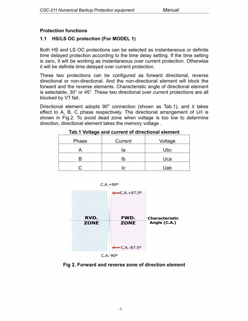
Both HS and LS OC protections can be selected as instantaneous or definitetime delayed protection according to the time delay setting. If the time settingis zero, it will be working as instantaneous over current protection. Otherwiseit will be definite time delayed over current protection.
These two protections can be configured as forward directional, reversedirectional or non-directional. And the non-directional element will block theforward and the reverse elements. Characteristic angle of directional elementis selectable, 30° or 45°. These two directional over current protections are allblocked by VT fail.
Directional element adopts 90o connection (shown as Tab.1), and it takeseffect to A, B, C phase respectively. The directional arrangement of U/I isshown in Fig.2. To avoid dead zone when voltage is too low to determinedirection, directional element takes the memory voltage .
Tab.1 Voltage and current of directional element
Phase Current Voltage
A Ia Ubc
B Ib Uca
C Ic Uab
FWD.
ZONE
RVD.
ZONECharacteristicAngle (C.A.)
C.A.+90º
C.A.-90º
C.A.+87.5º
C.A.-87.5º
Fig 2. Forward and reverse zone of direction element

CSC-211 Numerical Backup Protection equipment Manual
-8-
FWDIa>I
Phase A at FWD
AND
FWDIb>I
Phase B at FWD
AND
FWDIc>I
Phase C at FWD
AND
FWD element
ON
OFF
OR
RVDIa>I
Phase A at RVD
AND
RVDIb>I
Phase B at RVD
AND
RVDIc>I
Phase C at RVD
AND
RVD element
ON
OFF
OR
NODIa>I
NODIb>I
NODIc>I
NOD element
ON
OFF
OR
AND
AND
AND
T 0FWD
T 0RVD
T 0NOD
Relay Trip
Relay Trip
Relay Trip
Function
ON
OFF
VT Fail
Fig 3. Logic of HS/LS OC protection
The settings for HS OC protection is showed in Tab.2 and Tab.3.
Tab.2 Settings list for HS OC protection
No. Caption Scope Unit Memo
1 HS OC FWDI
0.05~100 AHigh set of current for over current at forwarddirection
2 HS OC RVD I 0.05~100 AHigh set of current for over current at reversedirection
3 HS OC NODI
0.05~100 AHigh set of current for over current at non-direction
4 HS OC FWDT
0.00~60.0 sHigh set of time for over current at forwarddirection

CSC-211 Numerical Backup Protection equipment Manual
-9-
5 HS OC RVDT
0.00~60.0 sHigh set of time for over current at reversedirection
6 HS OC NODT
0.00~60.0 sHigh set of time for over current at non-direction
Tab.3 Function element ON/OFF for HS OC protection
Bit Set to 0 Set to 1
Func Dir F/R Bit 2 HS OC FWD OFF HS OC FWD ON
Func Dir F/R Bit 3 HS OC RVD OFF HS OC RVD ON
Func Setting Bit 01 HS OC NOD OFF HS OC NOD ON
Func Bit 1 HS OC FUNC OFF HS OC FUNC ON
Func Setting Bit 13 C.A. of OC 30 C.A. of OC 45
The settings for LS OC protection is showed in Tab.4 and Tab.5.
Tab.4 Settings list for LS OC protection
No. Caption Scope Unit Remark
1 LS OC FWD I 0.05~100 ALow set of current for over current atforward direction
2 LS OC RVD I 0.05~100 ALow set of current for over current atreverse direction
3 LS OC NOD I 0.05~100 ALow set of current for over current at non-direction
4 LS OC FWDT
0.00~300 sLow set of time for over current at forwarddirection
5 LS OC RVDT
0.00~300 sLow set of time for over current at reversedirection
6 LS OC NODT
0.00~300 sLow set of time for over current at non-direction
Tab.5 Function element ON/OFF for LS OC protection
Bit Set to 0 Set to 1
Func Dir F/R Bit 4 LS OC FWD OFF LS OC FWD ON
Func Dir F/R Bit 5 LS OC RVD OFF LS OC RVD ON
Func Setting Bit 12 LS OC NOD OFF LS OC NOD ON
Func Bit Bit 2 LS OC FUNC OFF LS OC FUNC ON
Func Setting Bit 13 C.A. of OC 30 C.A. of OC 45
1.2 HS/LS EF protection (For MODEL 1)
Both HS and LS EF protection can be selected as instantaneous or definitetime delayed protection according to the time delay setting. If the time settingis zero, it will be working as instantaneous earth fault protection. Otherwise itwill be definite time delayed earth fault protection.

CSC-211 Numerical Backup Protection equipment Manual
-10-
These two protections can be configured as forward directional, reversedirectional or non-directional. And the non-directional element will block theforward and the reverse elements. Characteristic angle of directional elementis selectable, -45° or -60°. These two earth fault protections are all blocked byVT fail.
The directional arrangement of U/I is shown in Fig.2. The U is calculated bythree phase Voltage and the current I comes from analog input IN.
UCUBUAU ++=
The logic of HS/LS EF is showed in Fig 4.
FWDIN>I
IN at FWD
AND
FWD element
ON
OFF
RVDIN>I
IN at RVD
AND
RVD element
ON
OFF
NODIN>I
NOD element
ON
OFF
AND
AND
AND
T 0FWD
T 0RVD
T 0NOD
Relay Trip
Relay Trip
Relay Trip
Function
ON
OFF
VT Fail
Fig 4. Logic of HS/LS EF protection
The settings for HS EF protection is showed in Tab.6 and Tab.7.
Tab.6 Settings list for HS EF protection
No. Caption Scope Unit Memo
1 HS EFFWD I
0.05~100 AHigh set of current for earth fault at forwarddirection
2 HS EFRVD I
0.05~100 AHigh set of current for earth fault at reversedirection
3 HS EFNOD I
0.05~100 AHigh set of current for earth fault at non-direction
4 HS EFFWD T
0.00~60.0 sHigh set of time for earth fault at forwarddirection
5 HS EFRVD T
0.00~60.0 sHigh set of time for earth fault at reversedirection

CSC-211 Numerical Backup Protection equipment Manual
-11-
6 HS EFNOD T
0.00~60.0 sHigh set of time for earth fault at non-direction
Tab.7 Function element ON/OFF for HS EF protection
Bit Set to 0 Set to 1
Func Dir F/R Bit 8 HS EF FWD OFF HS EF FWD ON
Func Dir F/R Bit 9 HS EF RVD OFF HS EF RVD ON
Func Setting Bit 24 HS EF NOD OFF HS EF NOD ON
Func Bit Bit 4 HS EF FUNC OFF HS EF FUNC ON
Func Setting Bit 14 C.A. of EF -45 C.A. of EF -60
The settings for LS EF protection is showed in Tab.8 and Tab.9.
Tab.8 Settings list for LS EF protection
No. Caption Scope Unit Remark
1 LS EF FWDI
0.05~100 ALow set of current for earth fault at forwarddirection
2 LS EF RVDI
0.05~100 ALow set of current for earth fault at reversedirection
3 LS EF NODI
0.05~100 ALow set of current for earth fault at non-direction
4 LS EF FWDT
0.00~300 sLow set of time for earth fault at forwarddirection
5 LS EF RVDT
0.00~300 sLow set of time for earth fault at reversedirection
6 LS EF NODT
0.00~300 sLow set of time for earth fault at non-direction
Tab.9 Function element ON/OFF for LS EF protection
Bit Set to 0 Set to 1
Func Dir F/R Bit 10 LS EF FWD OFF LS EF FWD ON
Func Dir F/R Bit 11 LS EF RVD OFF LS EF RVD ON
Func Setting Bit 3 LS EF NOD OFF LS EF NOD ON
Func Bit Bit 5 LS EF FUNC OFF LS EF FUNC ON
Func Setting Bit 14 C.A. of EF -45 C.A. of EF -60
1.3 INV OC/EF protection (For MODEL 1)
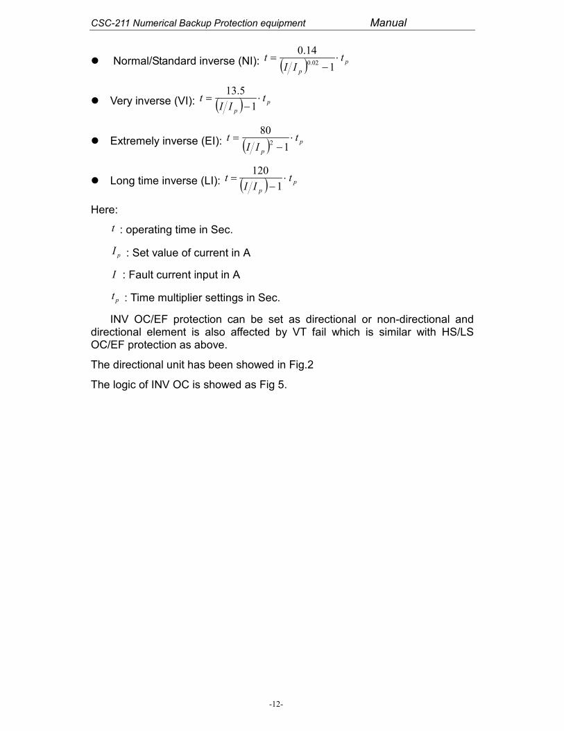
The operating time of the INV OC/EF function reduces when the fault currentincreases and it can therefore achieve shorter operating time for fault locationcloser to the source. Four different characteristics are provided and describedas follows:
CSC-211 Numerical Backup Protection equipment Manual
-12-
� Normal/Standard inverse (NI): ( ) p
p
tII
t ⋅−
=1
14.002.0
� Very inverse (VI): ( ) p
p
tII
t ⋅−
=1
5.13
� Extremely inverse (EI): ( ) p
p
tII
t ⋅−
=1
802
� Long time inverse (LI): ( ) p
p
tII
t ⋅−
=1
120
Here:
t : operating time in Sec.
pI : Set value of current in A
I : Fault current input in A
pt : Time multiplier settings in Sec.
INV OC/EF protection can be set as directional or non-directional anddirectional element is also affected by VT fail which is similar with HS/LSOC/EF protection as above.
The directional unit has been showed in Fig.2
The logic of INV OC is showed as Fig 5.

CSC-211 Numerical Backup Protection equipment Manual
-13-
FWDIa>I
Phase A at FWD
AND
FWDIb>I
Phase B at FWD
AND
FWDIc>I
Phase C at FWD
AND
FWD element
ON
OFF
RVDIa>I
Phase A at RVD
AND
RVDIb>I
Phase B at RVD
AND
RVDIc>I
Phase C at RVD
AND
RVD element
ON
OFF
NODIa>I
NODIb>I
NODIc>I
NOD element
ON
OFF
t FWD
Relay Trip
Relay Trip
Function
ON
OFF
VT Fail
AND
AND
AND
EXP FWD
t FWD
EXP FWD
t FWD
EXP FWD
OR
AND
AND
AND
t RVD
Relay Trip
EXP RVD
t RVD
EXP RVD
t RVD
EXP RVD
OR
OR AND t NOD
EXPNOD
Fig 5. Logic of INV OC protection
The settings for the INV OC protections are showed in Tab.10 and Tab.11.
Tab.10 Setting list for INV OC protection
No Caption Scope Unit Remark
1INV OC FWD
I0.05~100 A
Current set for INV over current at forwarddirection
2INV OC FWD
T0.005~5 s
Time set for INV over current at forward direction
3INV OC RVD
I0.05~100 A
Current set for INV over current at reversedirection
4INV OC RVD
T0.005~5 s
Time set for INV over current at reverse direction

CSC-211 Numerical Backup Protection equipment Manual
-14-
5INV OC NOD
I0.05~100 A
Current set for INV over current at non-direction
6INV OC NOD
T0.005~5 s
Time set for INV over current at non-direction
Tab.11 Function element ON/OFF for INV OC protection
Bit Set to 0 Set to 1
Func Dir F/R Bit 12 INV OC FWD OFF INV OC FWD ON
Func Dir F/R Bit 13 INV OC RVD OFF INV OC RVD ON
Func Setting Bit 4 INV OC NOD OFF INV OC NOD ON
Func Bit 6 INV OC FUNC OFF INV OC FUNC ON
Func Setting Bit 13 C.A. of EF 30 C.A. of EF 45
Curve selection of INV OC FWD
Func SelectionBit 1
Func Selection Bit0
Curve selection
“0” “0” Curve for INV OC FWD is normal inverse
“0” “1” Curve for INV OC FWD is very inverse
“1” “0” Curve for INV OC FWD is extremely inverse
“1” “1” Curve for INV OC FWD is long time inverse
Curve selection of INV OC RVD
Func SelectionBit 3
Func Selection Bit2
Curve selection
“0” “0” Curve for INV OC RVD is normal inverse
“0” “1” Curve for INV OC RVD is very inverse
“1” “0” Curve for INV OC RVD is extremely inverse
“1” “1” Curve for INV OC RVD is long time inverse
Curve selection of INV OC NOD
Func SelectionBit 5
Func Selection Bit4
Curve selection
“0” “0” Curve for INV OC NOD is normal inverse
“0” “1” Curve for INV OC NOD is very inverse
“1” “0” Curve for INV OC NOD is extremely inverse
“1” “1” Curve for INV OC NOD is long time inverse
The logic of INV EF is showed as Fig6.

CSC-211 Numerical Backup Protection equipment Manual
-15-
FWDIN>I
IN at FWD AND
FWD element
ON
OFF
RVDIN>I
IN at RVD
AND
RVD element
ON
OFF
NODIN>I
NOD element
ON
OFF
t FWD Relay Trip
Relay Trip
Function
ON
OFF
VT Fail
AND
EXP FWD
AND t RVD Relay Trip
EXP RVD
AND t NOD
EXPNOD
Fig 6. Logic of INV EF protection
The settings for INV EF protections are showed in Tab.12 and Tab.13.
Tab.12 Setting list for INV EF protection
No Caption Scope Unit Remark
1INV EF FWD
I0.05~100 A
Current set for INV earth fault at forward direction
2INV EF FWD
T0.005~5 s
Time set for INV earth fault at forward direction
3 INV EF RVD I 0.05~100 A Current set for INV earth fault at reverse direction
4INV EF RVD
T0.005~5 s
Time set for INV earth fault at reverse direction
5 INV EF NOD I 0.05~100 A Current set for INV earth fault at non-direction
6INV EF NOD
T0.005~5 s
Time set for INV earth fault at non-direction
Tab.13 Function element ON/OFF for INV EF protection
Bit Set to 0 Set to 1
Func Dir F/R Bit 14 INV EF FWD OFF INV EF FWD ON
Func Dir F/R Bit 15 INV EF RVD OFF INV EF RVD ON

CSC-211 Numerical Backup Protection equipment Manual
-16-
Func Setting Bit 5 INV EF NOD OFF INV EF NOD ON
Func Bit Bit 7 INV EF FUNC OFF INV EF FUNC ON
Func Setting Bit 14 C.A. of EF -45 C.A. of EF -60
Curve selection of INV EF FWD
Func Selection Bit7
Func Selection Bit6
Curve selection
“0” “0” Curve for INV EF FWD is normal inverse
“0” “1” Curve for INV EF FWD is very inverse
“1” “0” Curve for INV EF FWD is extremely inverse
“1” “1” Curve for INV EF FWD is long time inverse
Curve selection of INV EF RVD
Func Selection Bit9
Func Selection Bit8
Curve selection
“0” “0” Curve for INV EF RVD is normal inverse
“0” “1” Curve for INV EF RVD is very inverse
“1” “0” Curve for INV EF RVD is extremely inverse
“1” “1” Curve for INV EF RVD is long time inverse
Curve selection of INV EF NOD
Func Selection Bit11
Func Selection Bit10
Curve selection
“0” “0” Curve for INV EF NOD is normal inverse
“0” “1” Curve for INV EF NOD is very inverse
“1” “0” Curve for INV EF NOD is extremely inverse
“1” “1” Curve for INV EF NOD is long time inverse
1.4 Overload protection (For MODEL 1)
This protection is just a definite time-delayed (time can be set very long) over-current element.
The settings for overload protection are showed in Tab.14 and Tab.15.
Tab.14 Setting list for overload protection
No Caption Scope Unit Remark
1 Overload I 0.2~10 A Current set for overload protection
2 Overload T 0.1~6000 s Time set for overload protection
Tab.15 Function element ON/OFF for overload protection
Bit Set to 0 Set to 1
Func Bit Bit 10 OL FUNC OFF OL FUNC ON

CSC-211 Numerical Backup Protection equipment Manual
-17-
1.5 UV&OV protection (For MODEL 1 , 1a and 2)
When any phase-to-phase voltage in normal state turns to be less than ormore than predetermined value, it will result in tripping after predeterminedtime.
This protection includes two stages. Either stage can be chosen, i.e., eitherover voltage protection or under voltage protection and they have the sametime setting delay. It is showed in Fig 7.
Max Uphase-phase > UOV AND
AND
OR
AND
T 0 DO-UV&OV
Function
VT Fail
“ 1”
UV&OV is OV
UV&OV is UV
Min Uphase-phase < UUV
ON
OFF
DI input (CB closed) AND
Fig 7. Logic of UV&OV protection
The settings for the UV&OV protection is showed in Tab.16 and Tab.17
Tab.16 Setting list for UV&OV protection
No Caption Scope Unit Remark
46 for model1
24 for model1a
33 for model2
UV stg1 V 66~110 VVoltage set of under voltage for UV&OVat stage1
47 for model1
25 for model1a
34 for model2
OV stg1 V 110~154 VVoltage set of over voltage for UV&OVat stage1
48 for model1
26 for model1a
UV&OVstg1 T
0.1~10 s Time set for UV&OV at stage1

CSC-211 Numerical Backup Protection equipment Manual
-18-
35 for model1a
49 for model1
27 for model1a
36 for model2
UV stg2 V 66~110 VVoltage set of under voltage for UV&OVat stage2
50 for model1
28 for model1a
37 for model2
OV stg2 V 110~154 VVoltage set of over voltage for UV&OVat stage2
51 for model1
29 for model1a
38 for model2
UV&OVstg2 T
0.1~10 s Time set for UV&OV at stage2
Tab.17 Function element ON/OFF for UV&OV protection
Bit Set to 0 Set to 1
Func Setting Bit 11 for model 1
Func Bit 1 for model 1a
Func Setting Bit 14 for model 2
UV&OV stg1 UV UV&OV stg1 OV
Func Setting Bit 12
Func Bit 2 for model 1a
Func Setting Bit 15 for model 2
UV&OV stg2 UV UV&OV stg2 OV
Func Bit 12
Func Setting Bit 5 for model 1a
Func Bit 14 for model 2
UV&OV STG1 OFF UV&OV STG1 ON
Func Bit 13
Func Setting Bit 6 for model 1a
Func Bit 15 for model 2
UV&OV STG1 OFF UV&OV STG1 ON
1.6 Thermal overload protection (For MODEL 1)
This equipment provides thermal overload protection to the protectedequipment.
IEC curve:

CSC-211 Numerical Backup Protection equipment Manual
-19-
( )
−
−−=
22
22/1
lnθ
τII
ICHIt
eq
Peq
Where t = thermal trip time
eqI equivalent thermal current
τ thermal time constant
θI rms thermal current setting
CH / hot spot weighting factor
pI prior current takes into account cyclic loading
Here: τ , CH /1− and θI are all settings and 3
ICIBIAI eq
++= , pI equals
to the equivalent current before overload.
The settings for the thermal overload protection is showed in Tab.18 andTab.19
Tab.18 Setting list for the thermal overload protection
No Caption Scope Unit Remark
1 Thermal I 0.2~10 A Current set for thermal overload protection
2 Thermal T 6~7200 sTime set thermal for overload protection (thermaltime constant)
3 Thermal H/C 0~1 - hot spot weighting factor
Tab.19 Function element ON/OFF for thermal overload protection
Bit Set to 0 Set to 1
Func Bit 9 THERM FUNC OFF THERM FUNC ON
1.7 CBF protection (For MODEL 1)
Both single phase CBF and 3 phases CBF are provided in the CSC-211model 1.

CSC-211 Numerical Backup Protection equipment Manual
-20-
CBFI a>I
DI -START A_ph
AND
CBFI b>I
DI -START B_ph
CBFI c>I
DI -START C_ph
OR
I nt er nal t r i p
OR
T 0CBF
Funct i on
ON
OFF
AND
AND
DI -START 3_ph
OR
AND
AND
AND
AND
T 0CBF
T 0CBF
T 0CBF
CBF OPTD
I n>I nCBF
OR
CBF ALARM
Fig 8. Logic of CBF protection
The settings for the CBF protection is showed in Tab.20 and Tab.21
Tab.20 Setting list for the CBF protection
No Caption Scope Unit Remark
1 CBF OC I 0.05~100 A Current set for CBF protection
2 CBF EF I 0.05~100 A Current set for CBF protection
3 CBF T 0~32.00 s Time set for CBF protection
Tab.21 Function element ON/OFF for CBF protection
Bit Set to 0 Set to 1
Func Bit Bit 11 CBF FUNC OFF CBF FUNC ON
1.8 U/F&O/F protection (For MODEL 2)
When network frequency is abnormal, under frequency or over frequency, thisprotection will result in tripping after predetermined time. It has 7 stages, andevery stage can be selected as under frequency or over frequency protection.Stage 1 to stage 3 are “f or df/dt”, it means every stage (from 1 to 3) whenfrequency is less than setting or frequency negative change rate is greaterthan df/dt setting the equipment will give DO contacts, if you select underfrequency. And when you select over frequency, the conditions for tripping isfrequency is greater than setting or frequency positive change rate is greaterthan df/dt setting. For these three stages, the df/dt function can be ON or OFF.If df/dt is OFF, this stage is a simple under frequency or over frequencyprotection.
From stage 4 to stage 7, the protection function is written as “f & df/dt”. Inthese stages the df/dt is fixedly ON and the trip condition is that frequency isless than setting and frequency negative change rate is greater than settingwhen under frequency is selected. The trip condition for over frequency

CSC-211 Numerical Backup Protection equipment Manual
-21-
protection is that frequency is greater than setting and frequency positivechange rate is greater than setting. There are two elements to block thisprotection: VT fail and the minimum phase to phase voltage is less thansetting. The “f + df/dt” logic is showed in Fig 9 and “f & df/dt” is showed in Fig10.
VT Fai l
OR
ANDT 0
DO- f + df
Funct i on
UF
OF
ON
OFF
OR
“ 1”
UV Bl ock
f < f U
AND
df > df _neg
f < f N
dfON
OFF
f > f O
df > df _pos
f > f N
AND
AND
OR
T 0
T 0
T 0
OR
Fig 9. Logic of (f + df/dt) protection

CSC-211 Numerical Backup Protection equipment Manual
-22-
VT Fai l
AND
AND
DO- f & df
Funct i on
UF
OF
ON
OFF
OR
“ 1”
UV Bl ock
f < f U
AND
df > df _neg
f < f N
f > f O
df > df _pos
f > f N
AND
AND
ANDT 0
T 0
OR
Fig 10. Logic of (f & df/dt) protection
The settings for the U/F&O/F protection is showed in Tab.22 and Tab.23
Tab.22 Setting list for U/F&O/F protection
No Caption Scope Unit Remark
1 f + df/dt 1UF
40-49.99 HzFrequency set for under frequency protection atstage 1
2 f + df/dt 1OF
50.01-60 HzFrequency set for over frequency protection atstage 1
3 df/dt 1 0.1-10 Hz/s Frequency change rate set for f + df/dt at stage 1
4 f + df/dt 1 T 0-60 s Time set for f + df/dt protection at stage 1
5 f + df/dt 2UF
40-49.99 HzFrequency set for under frequency protection atstage 2
6 f + df/dt 2OF
50.01-60 HzFrequency set for over frequency protection atstage 2
7 df/dt 2 0.1-10.0 Hz/s Frequency change rate set for f + df/dt at stage 2
8 f + df/dt 2 T 0.0-60.0 s Time set for f + df/dt protection at stage 2
9 f + df/dt 3UF
40-49.99 HzFrequency set for under frequency protection atstage 3
10 f + df/dt 3OF
50.01-60 HzFrequency set for over frequency protection atstage 3
11 df/dt 3 0.1-10 Hz/s Frequency change rate set for f + df/dt at stage 3
12 f + df/dt 3 T 0 -60 s Time set for f + df/dt protection at stage 3

CSC-211 Numerical Backup Protection equipment Manual
-23-
13 f & df/dt 4UF
40-49.99 HzFrequency set for under frequency protection atstage 4
14 f & df/dt 4OF
50.01-60 HzFrequency set for over frequency protection atstage 4
15 df/dt 4 0.1-10.0 Hz/s Frequency change rate set for f & df/dt at stage 4
16 f & df/dt 4 T 0 -60 s Time set for f & df/dt protection at stage 4
17 f & df/dt 5UF
40- 49.99 HzFrequency set for under frequency protection atstage 5
18 f & df/dt 5OF
50.01-60 HzFrequency set for over frequency protection atstage 5
19 df/dt 5 0.1-10.0 Hz/s Frequency change rate set for f & df/dt at stage 5
20 f & df/dt 5 T 0-60 s Time set for f & df/dt protection at stage 5
21 f & df/dt 6UF
40-49.99 HzFrequency set for under frequency protection atstage 6
22 f & df/dt 6OF
50.01-60 HzFrequency set for over frequency protection atstage 6
23 df/dt 6 0.1-10.0 Hz/s Frequency change rate set for f & df/dt at stage 6
24 f & df/dt 6 T 0 - 60 s Time set for f & df/dt protection at stage 6
25 f & df/dt 7UF
40 - 49.99 HzFrequency set for under frequency protection atstage 7
26 f & df/dt 7OF
50.01-60 HzFrequency set for over frequency protection atstage 7
27 df/dt 7 0.1-10.0 Hz/s Frequency change rate set for f & df/dt at stage 7
28 f & df/dt 7 T 0-60 s Time set for f & df/dt protection at stage 7
Tab.23 Function element ON/OFF for U/F&O/F protection
Bit Set to 0 Set to 1
Func Bit bit 6 f & df/dt 7 OFF f & df/dt 7 ON
Func Bit bit 5 f & df/dt 6 OFF f & df/dt 6 ON
Func Bit bit 4 f & df/dt 5 OFF f & df/dt 5 ON
Func Bit bit 3 f & df/dt 4 OFF f & df/dt 4 ON
Func Bit bit 2 f + df/dt 3 OFF f + df/dt 3 ON
Func Bit bit 1 f + df/dt 2 OFF f + df/dt 2 ON
Func Bit bit 0 f + df/dt 1 OFF f + df/dt 1 ON
1.9 REF (For model 1a)
This function is operational only for fundamental frequency 50Hz. The relaywill not operate for charging current inrush of the Transformer and for anyother harmonics generated due to over excitation of the Transformer.

CSC-211 Numerical Backup Protection equipment Manual
-24-
Two stages are provided in model 1a. One is for alarm and one is for trip.
The settings for the REF protection is showed in Tab.24 and Tab.25
Tab.24 Setting list for REF protection
No Caption Scope Unit Remark
1 REF Alm I 0.05-6 A Current setting of REF alarm stage
2 REF Alm T 0-60 s Time setting of REF alarm stage
3 REF Trip I 0.05-6.00 A Current setting of REF trip stage
4 REF Trip T 0-60 s Time setting of REF trip stage
Tab.25 Function element ON/OFF for REF protection
Bit Set to 0 Set to 1
Func Setting bit 0 REF OP. Func OFF REF OP. Func ON
Func Setting bit 1 REF ALM Func OFF REF ALM Func ON
1.10 Over flux (For model 1a)
The over flux protection is used to detect impermissible over flux conditions
which can endanger transformers. The over flux protection must pick up when
the induction admissible for the protected transformers is exceeded. The
transformer is endangered, for example, if the power station block is
disconnected from the system for full-load and if the voltage regulator either
does not operate or does not operate sufficiently fast to control the associated
voltage rise. Similarly, decrease in frequency, e.g. in island system, can
endanger the transformer because of increased induction.
An increase in induction above the rated values leads very quickly to
saturation of the iron core and large eddy current losses. The over flux
protection feature serves to measure the voltage/frequency ratio which is
proportional to the B induction and puts it in relation to the BN nominal
induction. In this context, both voltage and frequency are related to nominal
values of the transformer to be protected.
*
*
f
U
fU
fU
B
BN
NNN
===
Where N : ratio of V/Hz.
U : voltage (phase voltage or phase to phase voltage is selectable ).
The over flux protection feature includes two staged characteristics and one
thermal characteristic for an approximate modeling of the heating which the
over flux may cause to the protected transformer. The inverse characteristic
can be set via thirteen points derived from the manufacturer data. In addition,

CSC-211 Numerical Backup Protection equipment Manual
-25-
a definite-time alarm stage and a definite-time trip stage can be used.
The settings for the over flux protection is showed in Tab.26 and Tab.27
Tab.26 Setting list for over flux protection
No Caption Scope Unit Remark
1 DEF V/F> Alm 1-2 ---- Ratio setting of over flux alarm stage
2 T DEF V/F>Alm
0.1-9999 sTime setting of over flux alarm stage
3 DEF V/F>>Trip
1.00-2.00 ----Ratio setting of definite time delay over fluxtrip stage
4 T DEF V/F>>Trip
0.1-9999 sTime setting of definite time delay over fluxtrip stage
5 T1 IVR R=1.10 0.1-9999 sTime setting of inverse time delay over fluxwhich stage’s ratio is 1.10
6 T2 IVR R=1.15 0.1-9999 sTime setting of inverse time delay over fluxwhich stage’s ratio is 1.10
7 T3 IVR R=1.20 0.1-9999 sTime setting of inverse time delay over fluxwhich stage’s ratio is 1.10
8 T4 IVR R=1.25 0.1-9999 sTime setting of inverse time delay over fluxwhich stage’s ratio is 1.10
9 T5 IVR R=1.30 0.1-9999 sTime setting of inverse time delay over fluxwhich stage’s ratio is 1.10
10 T6 IVR R=1.35 0.1-9999 sTime setting of inverse time delay over fluxwhich stage’s ratio is 1.10
11 T7 IVR R=1.40 0.1-9999 sTime setting of inverse time delay over fluxwhich stage’s ratio is 1.10
12 T8 IVR R=1.45 0.1-9999 sTime setting of inverse time delay over fluxwhich stage’s ratio is 1.10
13 T9 IVR R=1.50 0.1-9999 sTime setting of inverse time delay over fluxwhich stage’s ratio is 1.10
14 T10 IVRR=1.55
0.1-9999 sTime setting of inverse time delay over fluxwhich stage’s ratio is 1.10
15 T11 IVRR=1.60
0.1-9999 sTime setting of inverse time delay over fluxwhich stage’s ratio is 1.10
16 T12 IVRR=1.65
0.1-9999 sTime setting of inverse time delay over fluxwhich stage’s ratio is 1.10
17 T13 IVRR=1.65
0.1-9999 sTime setting of inverse time delay over fluxwhich stage’s ratio is 1.10
Tab.27 Function element ON/OFF for over flux protection
Bit Set to 0 Set to 1
Func Setting bit 2 DEF V/F> OP. OFF DEF V/F> OP. ON
Func Setting bit 3 DEF V/F> ALM OFF DEF V/F> ALM ON
Func Setting bit 3 IVR V/F> OFF DEF V/F> ON

CSC-211 Numerical Backup Protection equipment Manual
-26-
Func Bit bit 0 V/F V Pha V/F V Pha-Pha
1.11 VT supervision (For model 1, 1a and 2)
Voltage transformer supervision can supervise bus voltage and report single-phase broken, two-phase broken and three-phase broken if any of thefollowing conditions is satisfied for 9 seconds, CSC-211 will report the alarmof ‘VT FAIL’.
� Self-generated zero sequence voltage and three-phase voltage are allless than 8V and any phase current is more than 0.125A (considered asno-voltage, only for model 1);
� Self-generated zero sequence voltage is more than 8V and minimumphase-to-phase voltage is less than 16V (considered as two-phasebroken);
� Self-generated zero sequence voltage is more than 8V and the differencebetween maximum phase-to-phase voltage and minimum phase-to-phasevoltage is more than 16V (considered as single-phase broken).
For the directional protection, the perfect bus-voltage is significant for theiroperation. Therefore, VT fail will block the protection with directional elements,under voltage and frequency.
Tab.28 Function element ON/OFF for VT FAIL
Bit Set to 0 Set to 1
Func Bit 14 for M1 VT Fail OFF VT Fail ON
Func Setting bit 15 forM1a
VT Fail OFF VT Fail ON
Func Bit 7 for M2 VT Fail OFF VT Fail ON

CSC-211 Numerical Backup Protection equipment Manual
-27-
5 Technical Data
Rated inputs
DC Voltage:220V/110VAC Voltage:110V or VAC Current:1A/5AFrequency: 50Hz
BurdensDC circuit: < 25WAC Voltage/phase < 0.5VAAC Current/phase < 0.25VA
Thermalwithstand
AC Current1s @ 80×In10s @ 10×Incontinuous @ 2×InAC Voltage10s @ 1.4×Uncontinuous @ 1.2Un
ContactsMake: Carry continuous 5A AC or DC, 30A for 0.2sBreak: 1250VA AC, 75W DC resistive
Accuracy
Protection thresholds : ±3%Time delay : ±3% with a minimum of 20msMeasurements:
typical ±0.2 % at I, U
typical ±0.5 % at P,Q,kW, kVA
Report accuracyDistinguishability of event record: ≤ 1msPrecision of GPS: ≤ 1ms
Communications
RS485: Screened twisted pair,19200bps maxElectrical Ethernet: UTP5, RJ45 connectionFiber Ethernet: optical fiber,820nm, ST connection
High voltagewithstand
Insulation resistance:IEC 60255-5
Dielectric withstand:IEC 60255-52kV rms for 1 minute
Impulse voltage:IEC 60255-55kV, 1.2/50µs
EMC
Fast transient disturbance:IEC 61000-4-44kV, class 4
Electrostatic discharge:IEC 61000-4-28kV, class 4
Radio frequency:IEC 61000-4-310V/m
High frequency disturbance:IEC 60255-22-1 class 32.5kV common mode1kV differential mode
CSC-211 Numerical Backup Protection equipment Manual
-28-
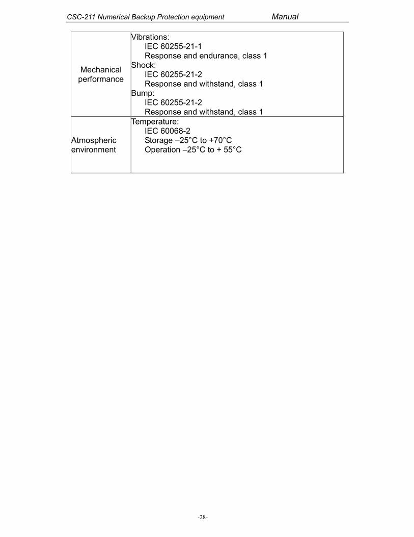
Mechanicalperformance
Vibrations:IEC 60255-21-1Response and endurance, class 1
Shock:IEC 60255-21-2Response and withstand, class 1
Bump:IEC 60255-21-2Response and withstand, class 1
Atmosphericenvironment
Temperature:IEC 60068-2Storage –25°C to +70°COperation –25°C to + 55°C

CSC-211 Numerical Backup Protection equipment Manual
-29-
6 Measurement and Control
6.1 Measurement
The CSC-211 equipment monitors permanently all the current and voltageinputs, calculates the frequency, the phase to phase voltage, P and Q; showsthe values on the LCD display and stores the measurements in memory. Themeasured values are measured by the independent high precision module,which can ensure the true RMS with 0.2% accuracy (nominal conditions).
Instantaneous measurements
Phase current: Ia, Ib, Ic;
Phase voltage: Ua, Ub, Uc;
Three phase active power P, reactive power Q, power factor;
Frequency;
Forward/reverse active power, forward/reverse reactive power;
6.2 Operation method control
The settings are divided into two categories: protection settings and controland support settings. 32 setting groups are provided for different operatingconditions and adaptive relaying. The soft function pressboards are providedfor activation or inhibition of the protection element. All settings and the statesof the soft function pressboards are stored in EEPROM.
6.3 Programmable scheme logic
The programmable scheme logic feature of support software EPPC allowsuser to customize the protection and control functions. It is also used toprogram the functionality of the optically isolated inputs, relay outputs andLED indications. The trigger conditions and the record length could easily beset by this function.

CSC-211 Numerical Backup Protection equipment Manual
-30-
7 Fault Record and Analysis
The CSC-211 equipment can supervise the operation information of thedevices and correlative circuit, which include fault records, event records,disturbance records and operation records. The internal real-time clockprovides the time-tag for all type records, the time distinguish ability is 1ms.The network synchronization and the GPS pulse (adaptive second or minutepulse) synchronization are supported by the real-time clock system. A lithiumbattery provides a backup for the real time clock and all records in the eventof supply failure. This battery is supervised and easily replaced from the frontof the relay.
7.1 Fault records
Records of the last 40 faults are stored in battery backed memory. Someimportant data during the fault or manual operation are recorded. Theinformation provided in the fault record includes:
Fault time tag: date and time
Operation event table: protection operation, operation time
Operation data: current, voltage, frequency, phase angle
Active setting groups
States of the soft function pressboards
7.2 Disturbance records
Disturbance records are used to capture the analog and digital data of certainlength before or after some event.It shows the operation states of the devicesduring the fault period, any logic element and digital input could trigger thedisturbance records. The internal disturbance recorder has 12 analogchannels, 32 digital channels (digital inputs, digital outputs, element states)and time tag. Data is sampled 20 times a cycle and typically 5 disturbancerecords, each of upto 1 seconds duration are stored in memory. Disturbancerecords can be extracted from the relay via the remote communications andsaved in the COMTRADE format. These records may be examined usingsupport software EPPC.

CSC-211 Numerical Backup Protection equipment Manual
-31-
7.3 Events records
Upto 1000 time-tagged event records are stored in battery backed memory,and can be extracted using the communication ports or showed on the frontpanel display. The event records include: operation events, alarm events,changing of digital input state or digital output state, time tag and the currentstatus of the protection.
7.4 Operation records
The latest 40 time-tagged operation records are stored in the battery backedmemory.It includes: the modification or switch of the setting groups, close oropen control of the circuit breaker. These data could provide information forthe detailed fault analysis.
8 Communications
All models of CSC-211 series equipments provide the followingcommunications ports and protocols for the user:
� Double or single 10M Ethernet port of cable or fiber.
� One RS485 communication port
� One RS232 debug port
� IEC60870-5-103
CSC-211 equipment can transmit real-time data to the local monitoring systemor remotely to the SCADA, these data include settings, measurements andalarms, as well as fault, event and disturbance records. The communicationsettings (relay address, data rate, parity, etc.) can be programmed using therelay front port. Software allows easy setting of any CSC-211 model, inaddition to uploading of event, fault and disturbance records, settings andmeasurements.
The detailed protocols are provided in the products manual.

CSC-211 Numerical Backup Protection equipment Manual
-32-
9 Diagnostics
Automatic tests including power-on diagnostics and continuous self-monitoring, ensure a high degree of reliability. When any abnormal status isdetected, the alarm indicators and related relay are driven and the dependentevents could be recorded immediately. For some fatal faults, the relay couldbe blocked to avoid the unwanted operation. The results of the self-testfunctions are stored in non-volatile memory.
The virtual test function is provided for the automatic tests of the substationautomation system. The function contains automatic counter point of digitalinput, automatic triggering of SOE.
Test features available on the user interface provide examination of inputquantities, states of the digital inputs and relay outputs. A local monitor portprovides digital outputs, selected from a prescribed list of signals, includingthe status of protection element and may be used in conjunction with testequipment. These test signals can also be viewed using the communicationports and the front panel user interface.

CSC-211 Numerical Backup Protection equipment Manual
-33-
10 Setting Table
10.1 Setting list for MODEL 1
Setting List and Description
No. Caption Scope Unit Memo Function
1 Func Dir F/R 0000:FFFF For forward and reversedirectional element
2 Func Setting 0000:FFFF For UV/OV, C.A. and rated
3 Func Bit 0000:FFFF Function selective
4 Func Selection 0000:FFFF
5 HS OC FWD I 0.05:100 A
6 HS OC RVD I 0.05:100 A
7 HS OC NOD I 0.05:100 A
8 HS OC FWD T 0.0:60.00 s
9 HS OC RVD T 0.0:60.00 s
10 HS OC NOD T 0.0:60.00 s
11 LS OC FWD I 0.05:100 A
12 LS OC RVD I 0.05:100 A
13 LS OC NOD I 0.05:100 A
14 LS OC FWD T 0.0:300.0 s
15 LS OC RVD T 0.0:300.0 s
16 LS OC NOD T 0.0:300.0 s
OC
17 HS EF FWD I 0.05:100 A
18 HS EF RVD I 0.05:100 A
19 HS EF NOD I 0.05:100 A
20 HS EF FWD T 0.0:60.00 s
21 HS EF RVD T 0.0:60.00 s
22 HS EF NOD T 0.0:60.00 s
23 LS EF FWD I 0.05:100 A
24 LS EF RVD I 0.05:100 A
25 LS EF NOD I 0.05:100 A
26 LS EF FWD T 0.0:300.0 s
27 LS EF RVD T 0.0:300.0 s
28 LS EF NOD T 0.0:300.0 s
EF
29 INV OC FWD I 0.05:100 A
30 INV OC FWD T 0.005:5 s
31 INV OC RVD I 0.05:100 A
32 INV OC RVD T 0.005:5 s
33 INV OC NOD I 0.05:100 A
34 INV OC NOD T 0.005:5 s
INV OC
35 INV EF FWD I 0.05:100 A
36 INV EF FWD T 0.005:5 s
37 INV EF RVD I 0.05:100 A
38 INV EF RVD T 0.005:5 s
39 INV EF NOD I 0.05:100 A
40 INV EF NOD T 0.005:5 s
INV EF
41 Thermal I 0.2:10.0 A OL

CSC-211 Numerical Backup Protection equipment Manual
-34-
No. Caption Scope Unit Memo Function
42 Thermal T 6:7200 s
43 Thermal H/C 0.0:1
44 Overload I 0.2:10.0 A
45 Overload T 0.1:6000 s
46 UV stg1 V 66.0:110.0V V Phase-to-Phase
47 OV stg1 V 110.0:154.0 V Phase-to-Phase
48 UV&OV stg1 T 0.1:10.0 s
49 UV stg2 V 66.0:110.0V V Phase-to-Phase
50 OV stg2 V 110.0:154.0 V Phase-to-Phase
51 UV&OV stg2 T 0.1:10.0 s
UV&OV
52 CBF OC I 0.05 A:100 A
53 CBF EF I 0.05 A:100 A
54 CBF T 0.1:32.00 s
CBF
55 Ipha_abupt 0.05 A:100 A
56 Ineu_abupt 0.05 A:100 A
57 Mea CT Ratio 0.001:10.0 kA/A Primary Mea CT /1000
58 Mea VT Ratio 0.01:10.0 kV/V Primary PT/1000
Definition of Func Dir F/R
BIT “0” “1”
15 INV EF FWD OFF INV EF FWD ON
14 INV EF FWD OFF INV EF FWD ON
13 INV OC RVD OFF INV OC RVD ON
12 INV OC FWD OFF INV OC FWD ON
11 LS EF RVD OFF LS EF RVD ON
10 LS EF FWD OFF LS EF FWD ON
9 HS EF RVD OFF HS EF RVD ON
8 HS EF FWD OFF HS EF FWD ON
7 Not used Not used
6 Not used Not used
5 LS OC RVD OFF LS OC RVD ON
4 LS OC FWD OFF LS OC FWD ON
3 HS OC RVD OFF HS OC RVD ON
2 HS OC FWD OFF HS OC FWD ON
1 Not used Not used
0 Not used Not used

CSC-211 Numerical Backup Protection equipment Manual
-35-
Definition of Func Setting
BIT “0” “1”
15 Not used Not used
14 C.A. of EF -45 C.A.of EF -60
13 C.A.of OC 30 C.A.of OC 45
12 UV&OV stg2 UV UV&OV stg2 OV
11 UV&OV stg1 UV UV&OV stg1 OV
10 Not used Not used
9 Not used Not used
8 Neu CT Rated 5A Neu CT Rated 1A
7 Pha CT Rated 5A Pha CT Rated 1A
6 Not used Not used
5 INV EF NOD OFF INV EF NOD ON
4 INV OC NOD OFF INVOC NOD ON
3 LS EF NOD OFF LS EF NOD ON
2 HS EF NOD OFF HS EF NOD ON
1 LS OC NOD OFF LS OC NOD ON
0 HS OC NOD OFF HS OC NOD ON
Definition of Func Bit
BIT “0” “1”
15 Not used Not used
14 VT Fail OFF VT Fail ON
13 UV&OV STG1 OFF UV&OV STG1 ON
12 UV&OV STG1 OFF UV&OV STG1 ON
11 CBF FUNC OFF CBF FUNC ON
10 OL FUNC OFF OL FUNC ON
9 THERM FUNC OFF THERM FUNC ON
8 Not used Not used
7 INV EF FUNC OFF INV EF FUNC ON
6 INV OC FUNC OFF INV OC FUNC ON
5 LS EF FUNC OFF LS EF FUNC ON
4 HS EF FUNC OFF HS EF FUNC ON
3 Not used Not used
2 LS OC FUNC OFF LS OC FUNC ON
1 HS OC FUNC OFF HS OC FUNC ON
0 Not used Not used

CSC-211 Numerical Backup Protection equipment Manual
-36-
Definition of Func Selection
BIT “0” “1”
15 Not used Not used
14
13
12
SECECT BEING BLOCKED FUNCTION BY BLOCKONG I/P
11
10CURVE SELECTION OF INV EF NOD
9
8CURVE SELECTION OF INV EF RVD
7
6CURVE SELECTION OF INV EF FWD
5
4CURVE SELECTION OF INV OC NOD
3
2CURVE SELECTION OF INV OC RVD
1
0CURVE SELECTION OF INV OC FWD
CURVE SELECTION OF INV OC FWD
BIT 1 BIT 0 CURVE SELECTION
“0” “0” Normal inverse
“0” “1” Very inverse
“1” “0” Extremely inverse
“1” “1” Long time inverse
CURVE SELECTION OF INV OC RVD
BIT 3 BIT 2 CURVE SELECTION
“0” “0” Normal inverse
“0” “1” Very inverse
“1” “0” Extremely inverse
“1” “1” Long time inverse
CURVE SELECTION OF INV OC NOD
BIT 5 BIT4 CURVE SELECTION
“0” “0” Normal inverse
“0” “1” Very inverse
“1” “0” Extremely inverse
“1” “1” Long time inverse

CSC-211 Numerical Backup Protection equipment Manual
-37-
CURVE SELECTION OF INV EF FWD
BIT 7 BIT 6 CURVE SELECTION
“0” “0” Normal inverse
“0” “1” Very inverse
“1” “0” Extremely inverse
“1” “1” Long time inverse
CURVE SELECTION OF INV EF RVD
BIT 9 BIT 8 CURVE SELECTION
“0” “0” Normal inverse
“0” “1” Very inverse
“1” “0” Extremely inverse
“1” “1” Long time inverse
CURVE SELECTION OF INV EF NOD
BIT 11 BIT 10 CURVE SELECTION
“0” “0” Normal inverse
“0” “1” Very inverse
“1” “0” Extremely inverse
“1” “1” Long time inverse
SECECT BLOCKED FUNCTION BY BLOCKONG I/P
BIT 14 BIT 13 BIT 12 Being blocked function
“0” “0” “0” I/P BLK NONE
“0” “0” “1” I/P BLK INV OC
“0” “1” “0” I/P BLK INV EF
“0” “1” “1” I/P BLK LS OC
“1” “0” “0” I/P BLK LS EF
“1” “0” “1” I/P BLK UV&OV 1
“1” “1” “0” I/P BLK UV&OV 2
“1” “1” “1” Not used

CSC-211 Numerical Backup Protection equipment Manual
-38-
10.2 Setting list for MODEL 1a
Setting List and Description
No. Caption Scope Unit Memo Function
1 Func Bit 0000:FFFF For UV or OV, DI block
2 Func Setting 0000:FFFF Functions selection ON or
3 REF Alm I 0.05:6.00 A
4 REF Alm T 0.00:60.00 s
5 REF Trip I 0.00:6.00 A
6 REF Trip T 0.0:60.00 s
REF twostages
7 DEF V/F> Alm 1.00:2.00 -----
8 T DEF V/F Alm 0.1:9999 s
9 DEF V/F>> Trip 1.00:2.00 -----
10 T DEF V/F Trip 0.1:9999 s
Definite timedelay stagesfor over flux
11 T1 IVR R=1.10 0.1:9999 s
12 T2 IVR R=1.15 0.1:9999 s
13 T3 IVR R=1.20 0.1:9999 s
14 T4 IVR R=1.25 0.1:9999 s
15 T5 IVR R=1.30 0.1:9999 s
16 T6 IVR R=1.35 0.1:9999 s
17 T7 IVR R=1.40 0.1:9999 s
18 T8 IVR R=1.45 0.1:9999 s
19 T9 IVR R=1.50 0.1:9999 s
20 T10 IVR R=1.55 0.1:9999 s
21 T11 IVR R=1.60 0.1:9999 s
22 T12 IVR R=1.65 0.1:9999 s
23 T13 IVR R=1.65 0.1:9999 s
Inverse timedelay for over
flux (13stages)
24 UV stg1 V 66.0:110.0V V Phase-to-Phase
25 OV stg1 V 110.0:154.0 V Phase-to-Phase
26 UV&OV stg1 T 0.1:10.0 s
27 UV stg2 V 66.0:110.0V V Phase-to-Phase
28 OV stg2 V 110.0:154.0 V Phase-to-Phase
29 UV&OV stg2 T 0.1:10.0 s
UV&OV
30 Mea CT Ratio 0.001:10.0 kA/A Primary Mea CT /1000
31 Mea PT Ratio 0.01:10.0 kV/V Primary PT/1000

CSC-211 Numerical Backup Protection equipment Manual
-39-
Definition of Func Bit
BIT “0” “1”
6~15 Not used Not used
5
4SECECT BEING BLOCKED FUNCTION BY BLOCKONG I/P
3 Not used Not used
2 UV&OV stg2 UV UV&OV stg2 OV
1 UV&OV stg1 UV UV&OV stg1 OV
0 V/f V Pha V/f V Pha-Pha
Definition of Func Setting
BIT “0” “1”
15 VT Fail OFF VT Fail ON
14 Not used Not used
13 Not used Not used
12 DI2 OP. FUNC OFF DI2 OP. FUNC ON
11 DI1 OP. FUNC OFF DI1 OP. FUNC ON
10 Not used Not used
9 Not used Not used
8 Not used Not used
7 Not used Not used
6 UV&OV STG2 OFF UV&OV STG2 ON
5 UV&OV STG1 OFF UV&OV STG1 ON
4 IVR V/F> OFF IVR V/F> ON
3 DEF V/F> ALM OFF DEF V/F> ALM ON
2 DEF V/F> OP. OFF DEF V/F> OP. ON
1 REF ALM FUNC OFF REF ALM FUNC ON
0 REF OP. FUNC OFF REF OP. FUNC ON
SECECT BLOCKED FUNCTION BY BLOCKONG I/P
BIT 5 BIT 4 Being blocked function
“0” “0” I/P BLK NONE
“0” “1” I/P BLK V/F
“1” “0” I/P BLK UV&OV1
“1” “1” I/P BLK UV&OV2

CSC-211 Numerical Backup Protection equipment Manual
-40-
10.3 Setting list for MODEL 2
Setting List and Description
No. Caption Scope Unit Memo Function
1 Func Bit 0000:FFFF Functions selection ON or
2 Func Setting 0000:FFFF For UV/OV, df/dt, OF/UF
3 DI BLK Func 0000:FFFF DI blocking functions
4 f + df/dt 1 UF 40.00:49.99 Hz
5 f + df/dt 1 OF 50.01:55.00 Hz
6 df/dt 1 0.10:10.00 Hz/s
7 f + df/dt 1 T 0.0:60.00 s
f stage 1
8 f + df/dt 2 UF 40.00:49.99 Hz
9 f + df/dt2 OF 50.01:55.00 Hz
10 df/dt 2 0.10:10.00 Hz/s
11 f + df/dt 2 T 0.0:60.00 s
f stage 2
12 f + df/dt 3 UF 40.00:49.99 Hz
13 f + df/dt 3 OF 50.01:55.00 Hz
14 df/dt 3 0.10:10.00 Hz/s
15 f + df/dt 3 T 0.0:60.00 s
f stage 3
16 f & df/dt 4 UF 40.00:49.99 Hz
17 f & df/dt 4 OF 50.01:55.00 Hz
18 df/dt 4 0.10:10.00 Hz/s
19 f & df/dt 4 T 0.0:60.00 s
f stage 4
20 f & df/dt 5 UF 40.00:49.99 Hz
21 f & df/dt 5 OF 50.01:55.00 Hz
22 df/dt 5 0.10:10.00 Hz/s
23 f & df/dt 5 T 0.0:60.00 s
f stage 5
24 f & df/dt 6 UF 40.00:49.99 Hz
25 f & df/dt 6 OF 50.01:55.00 Hz
26 df/dt 6 0.10:10.00 Hz/s
27 f & df/dt 6 T 0.0:60.00 s
f stage 6
28 f & df/dt 7 UF 40.00:49.99 Hz
29 f & df/dt 7 OF 50.01:55.00 Hz
30 df/dt 7 0.10:10.00 Hz/s
31 f & df/dt 7 T 0.0:60.00 s
f stage 7
32UF&OF BLOCK
UV20.0:120.0 V
33 UV stg1 V 66.0:110.0V V Phase-to-Phase
34 OV stg1 V 110.0:154.0 V Phase-to-Phase
35 UV&OV stg1 T 0.1:10.0 s
36 UV stg2 V 66.0:110.0V V Phase-to-Phase
37 OV stg2 V 110.0:154.0 V Phase-to-Phase
38 UV&OV stg2 T 0.1:10.0 s
UV&OV
39 Mea CT Ratio 0.001:10.0 kA/A Primary Mea CT /1000
40 Mea PT Ratio 0.01:10.0 kV/V Primary PT/1000

CSC-211 Numerical Backup Protection equipment Manual
-41-
Definition of Func Bit
BIT “0” “1”
15 UV&OV stg2 OFF UV&OV stg2 ON
14 UV&OV stg1 OFF UV&OV stg1 ON
13 Not used Not used
12 Not used Not used
8~11 Not used Not used
7 VT Fail OFF VT Fail ON
6 f & df/dt7 OFF f & df/dt7 ON
5 f & df/dt6 OFF f & df/dt6 ON
4 f & df/dt5 OFF f & df/dt5 ON
3 f & df/dt4 OFF f & df/dt4 ON
2 f + df/dt3 OFF f + df/dt3 ON
1 f + df/dt2 OFF f + df/dt2 ON
0 f + df/dt1 OFF f + df/dt1 ON
Definition of Func Setting
BIT “0” “1”
15 UV&OV stg2 UV UV&OV stg2 OV
14 UV&OV stg1 UV UV&OV stg1 OV
13 df/dt 3 OFF df/dt 3 ON
12 df/dt 2 OFF df/dt 2 ON
11 df/dt 1 OFF df/dt 1 ON
8~10 Not used Not used
7 Pha CT Rated 5A Pha CT Rated 1A
6 f & df/dt 7 UF f & df/dt 7 OF
5 f & df/dt 6 UF f & df/dt 6 OF
4 f & df/dt 5 UF f & df/dt 5 OF
3 f & df/dt 4 UF f & df/dt 4 OF
2 f + df/dt 3 UF f + df/dt 3 OF
1 f + df/dt 2 UF f + df/dt 2 OF
0 f + df/dt 1 UF f + df/dt 1 OF

CSC-211 Numerical Backup Protection equipment Manual
-42-
Definition of DI Blk Func
BIT “0” “1”
10~15 Not used Not used
9
8
BLOCK IP2 can be selected to block any function: UV&OV stage 1,UV&OV stage 1.
7
6
5
BLOCK IP2 can be selected to block any function: f stage 1, f stage 2,f stage 3, f stage 4, f stage 5, f stage 6, f stage 7.
4
3
BLOCK IP1 can be selected to block any function: UV&OV stage 1,UV&OV stage 1.
2
1
0
BLOCK IP1 can be selected to block any function: f stage 1, f stage 2,f stage 3, f stage 4, f stage 5, f stage 6, f stage 7.
SECECT BLOCKED FUNCTION BY BLOCKONG I/P1
BIT 2 BIT 1 BIT 0 Being blocked function
“0” “0” “0” Not used
“0” “0” “1” IP1 BLK f 1
“0” “1” “0” IP1 BLK f 2
“0” “1” “1” IP1 BLK f 3
“1” “0” “0” IP1 BLK f 4
“1” “0” “1” IP1 BLK f 5
“1” “1” “0” IP1 BLK f 6
“1” “1” “1” IP1 BLK f 7
SECECT BLOCKED FUNCTION BY BLOCKONG I/P1
BIT 4 BIT 3 Being blocked function
“0” “0” Not used
“0” “1” IP1 BLK UV&OV1
“1” “0” IP1 BLK UV&OV2
“1” “1” IP1 BLK NONE
BLOCKING I/P 1 can be programmed to block selective function. One stageof frequency protections and one stage of UV&OV protections can beselected to be blocked by BLOCKING I/P 1 at the same time. But if “IP1 BLKNONE” is selected ( BIT 4 and BIT 3 are all “1”), then BLOCKING I/P will notblock anyone.

CSC-211 Numerical Backup Protection equipment Manual
-43-
SECECT BLOCKED FUNCTION BY BLOCKONG I/P2
BIT 7 BIT 6 BIT 5 Being blocked function
“0” “0” “0” Not used
“0” “0” “1” IP2 BLK f 1
“0” “1” “0” IP2 BLK f 2
“0” “1” “1” IP2 BLK f 3
“1” “0” “0” IP2 BLK f 4
“1” “0” “1” IP2 BLK f 5
“1” “1” “0” IP2 BLK f 6
“1” “1” “1” IP2 BLK f 7
SECECT BLOCKED FUNCTION BY BLOCKONG I/P2
BIT 9 BIT 8 Being blocked function
“0” “0” Not used
“0” “1” IP2 BLK UV&OV1
“1” “0” IP2 BLK UV&OV2
“1” “1” IP2 BLK NONE
BLOCKING I/P 2 can be programmed to block selective function. One stageof frequency protections and one stage of UV&OV protections can beselected to be blocked by BLOCKING I/P 2 at the same time. But if “IP2 BLKNONE” is selected (BIT 9 and BIT 8 are all “1”), then BLOCKING I/P will notblock anyone.

CSC-211 Numerical Backup Protection equipment Manual
-44-
11 Selection and ordering data
PositionOrdering
Codes
1 2 3 4 5 6 7 8 9
CSC 211-
10
/
2 Phases Mea TA(Blank) 0
2. AC1 Module
3. AC2 Module Phase rated current 1A and neutral 1A(M1) G
4. COM Module
IEC61850 6
5. CPU Module
6. LOGIC1 Module
8. POWER ModuleRated Auxiliary DC110V 1
9. MMI Module
10. Structural Style
1. Software Version
CSC-211 0
Digital Feeder/ REF/Frequency protection Equipment
6 6
Phase rated current 1A and neutral 5A(M1) Q
Phase rated current 5A and neutral 5A(M1) L
Phase rated current 5A and neutral 1A(M1) B
Model 2 (U/F&O/F) 2
Blank 0
Model 1a (REF) 1a
Model 1 (CBF) 1
3 Phases Mea TA H
New type CT for neutral currentX M1aX F
Calculate frequency through hardware (M2) M
New version of filter circuit (M1) 4
8
Old version of filter circuit (M1a&M2) 2
6
7. LOGIC2 Module8
Rated Auxiliary DC110V 2
1
K
1 K

CSC-211 Numerical Backup Protection equipment Manual
-45-
12 Dimension drawings in mm
Dimension drawings for CSC-211 used 19/2 inch (4U) enclosure for panelflush-mounting and cabinet mounting.
Fig.10 Flush-mounted enclosure of CSC-211 with panel cutout

CSC-211 Numerical Backup Protection equipment Manual
-46-
14Menu Frame
Abbr.(LCD Display)
Meaning Remarks
OpStatus Operating Status
Analog Analog InputInspecting the analog input of theequipment.
MeasureMeasurement analoginput
Inspecting the measurement analog inputof the equipment.
DI Status of digital inputs Inspecting the status of digital inputs.
OpConfig
SetGr Settings Group Switching setting group
Time Configuring time
Settings Settings operation
Read Read settings
Write Write settings
Switch Switch settings group
Delete Delete settings
Report Query and manage report
Event Query the event report
Listing the time of the event reports whichis searched by time sect, selecting thereport with ▲ and ▼ key, inspecting thecontent with SET key.
Alarm Query the alarm report
Listing the time of the alarm reports whichis searched by time sect, selecting thereport with ▲ and ▼ key, inspecting thecontent with SET key.
WaveQuery the report withwave
Listing the time of the reports with wavewhich is searched by time sect, selectingthe report with ▲ and ▼ key, inspectingthe content with SET key.
Operate Query the operate report
Listing the time of the operate reportswhich is searched by time sect, selectingthe report with ▲ and ▼ key, inspectingthe content with SET key.
Erase Erase report
Erase event Erase the event reports Erase all the event reports
Erase Alarm Erase the alarm reports Erase all the alarm reports
Erase WaveErase the reports withwave
Erase all the reports with wave
ComConf Communication Configure
Ether 1# Ethernet port 1 Set Ethernet port 1 in CPU module
Ether 2# Ethernet port 2 Set Ethernet port 2 in CPU module
Serial Set serial port
Type Communication typeselect COM for 61850, select RS232 forEPPC, and select RS485 for IEC103
BaudRate Baud rate select 9600
CSC-211 Numerical Backup Protection equipment Manual
-47-
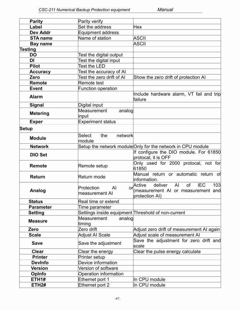
Parity Parity verify
Label Set the address Hex
Dev Addr Equipment address
STA name Name of station ASCII
Bay name ASCII
Testing
DO Test the digital output
DI Test the digital input
Pilot Test the LED
Accuracy Test the accuracy of AI
Zero Test the zero drift of AI Show the zero drift of protection AI
Remote Remote test
Event Function operation
AlarmInclude hardware alarm, VT fail and tripfailure
Signal Digital input
MeteringMeasurement analoginput
Exper Experiment status
Setup
ModuleSelect the networkmodule
Network Setup the network moduleOnly for the network in CPU module
DIO SetIf configure the DIO module. For 61850protocal, it is OFF
Remote Remote setupOnly used for 2000 protocal, not for61850
Return Return modeManual return or automatic return ofinformation.
AnalogProtection AI ormeasurement AI
Active deliver AI of IEC 103(measurement AI or measurement andprotection AI)
Status Real time or extend
Parameter Time parameter
Setting Settings inside equipment Threshold of non-current
MeasureMeasurement analogtiming
Zero Zero drift Adjust zero drift of measurement AI again
Scale Adjust AI Scale Adjust scale of measurement AI
Save Save the adjustmentSave the adjustment for zero drift andscale
Clear Clear the energy Clear the pulse energy calculate
Printer Printer setup
DevInfo Device information
Version Version of software
OpInfo Operation information
ETH1# Ethernet port 1 In CPU module
ETH2# Ethernet port 2 In CPU module

CSC-211 Numerical Backup Protection equipment Manual
-48-


