Download - Cross Laminated Timber Design Guide

CrossLamTM
by STRUCTURLAM Cross Laminated Timber
Design Guide
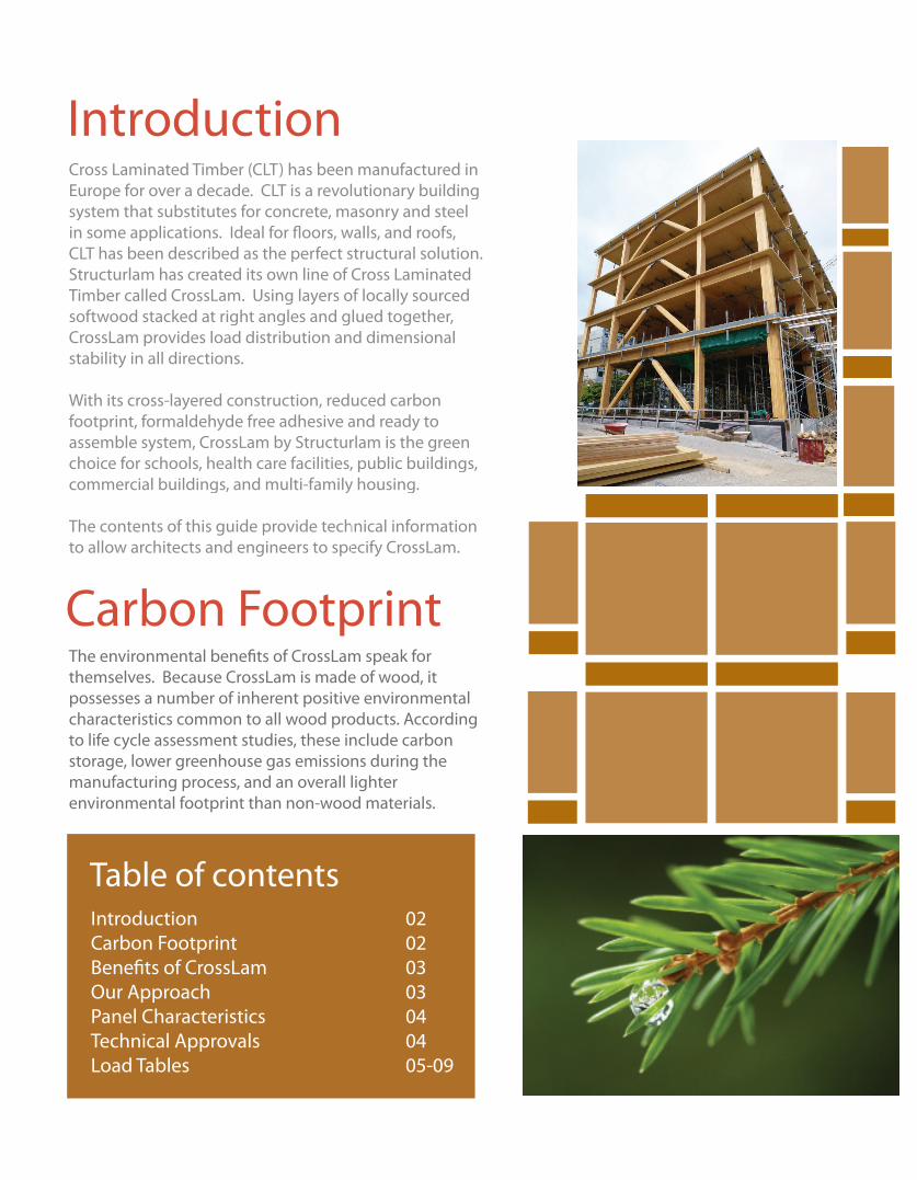
Cross Laminated Timber (CLT) has been manufactured in Europe for over a decade. CLT is a revolutionary building system that substitutes for concrete, masonry and steel in some applications. Ideal for fl oors, walls, and roofs, CLT has been described as the perfect structural solution. Structurlam has created its own line of Cross Laminated Timber called CrossLam. Using layers of locally sourced softwood stacked at right angles and glued together, CrossLam provides load distribution and dimensional stability in all directions.
With its cross-layered construction, reduced carbon footprint, formaldehyde free adhesive and ready to assemble system, CrossLam by Structurlam is the green assemble system, CrossLam by Structurlam is the green choice for schools, health care facilities, public buildings, choice for schools, health care facilities, public buildings, commercial buildings, and multi-family housing. commercial buildings, and multi-family housing. commercial buildings, and multi-family housing. commercial buildings, and multi-family housing. commercial buildings, and multi-family housing. commercial buildings, and multi-family housing.
The contents of this guide provide technical information The contents of this guide provide technical information The contents of this guide provide technical information The contents of this guide provide technical information The contents of this guide provide technical information The contents of this guide provide technical information to allow architects and engineers to specify CrossLam. to allow architects and engineers to specify CrossLam. to allow architects and engineers to specify CrossLam. to allow architects and engineers to specify CrossLam. to allow architects and engineers to specify CrossLam. to allow architects and engineers to specify CrossLam.
Introduction
Introduction 02Carbon Footprint 02Benefi ts of CrossLam 03Our Approach 03Panel Characteristics 04Technical Approvals 04Load Tables 05-09
Table of contents
Carbon FootprintThe environmental benefi ts of CrossLam speak for themselves. Because CrossLam is made of wood, it possesses a number of inherent positive environmental characteristics common to all wood products. According to life cycle assessment studies, these include carbon storage, lower greenhouse gas emissions during the manufacturing process, and an overall lighter environmental footprint than non-wood materials.
Benefi ts of CrossLamCrossLam has many of the benefi ts that other building materials just don’t have.
Up to 6 times lighter than concrete. • Dimensional stability and static strength in all directions.• Cost competitive against steel and concrete. • Reduced construction time. • Space creator, 1/3 thinner than concrete. • Less demand for skilled workers on site. •
Our ApproachStructurlam’s CrossLam has all the advantages of prefabricated buildings in addition to the Structurlam Advantage:
Our state of the art manufacturing facility allows us to effi ciently produce • large volumes of world class, certifi ed panels.Our planer can fi nish smooth all 4 sides to expose panel surfaces and ensure • a perfect fi t. Our Design Team can provide fully engineered design solutions for fl oors, • roof, walls, and all connection details. Our Installation Team can install any size of project. • We manufacture panels using environmentally friendly resins that are free • from formaldehyde and colour. The Structurlam Team is here to make your project a success.•
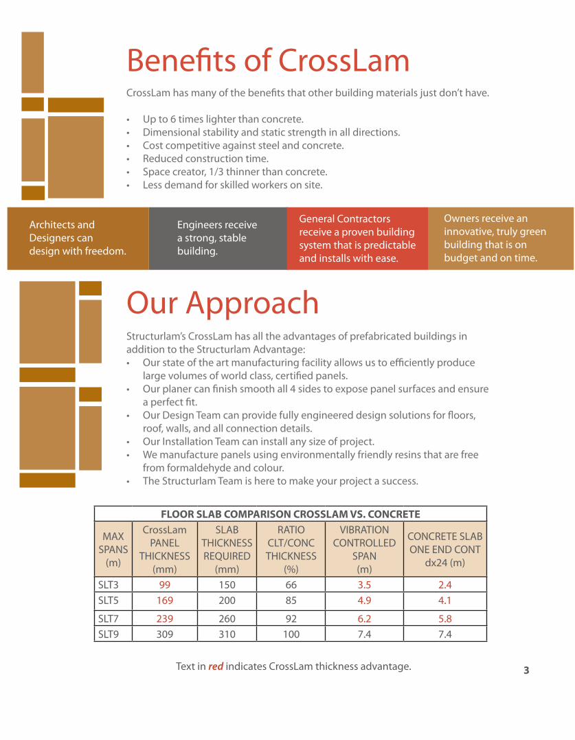
FLOOR SLAB COMPARISON CROSSLAM VS. CONCRETE
MAX SPANS
(m)
CrossLam PANEL
THICKNESS (mm)
SLAB THICKNESS REQUIRED
(mm)
RATIO CLT/CONC THICKNESS
(%)
VIBRATION CONTROLLED
SPAN (m)
CONCRETE SLAB ONE END CONT
dx24 (m)
SLT3 99 150 66 3.5 2.4SLT5 169 200 85 4.9 4.1
SLT7 239 260 92 6.2 5.8SLT9 309 310 100 7.4 7.4
Text in red indicates CrossLam thickness advantage. 3
Architects and Designers can design with freedom.
Engineers receive a strong, stable building.
General Contractors receive a proven building system that is predictable and installs with ease.
Owners receive an innovative, truly green building that is on budget and on time.
Panel Layouts
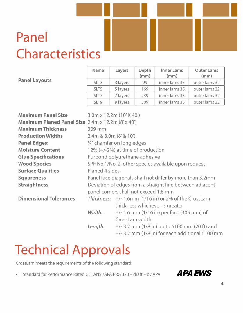
Maximum Panel Size 3.0m x 12.2m (10’ X 40’)Maximum Planed Panel Size 2.4m x 12.2m (8’ x 40’)Maximum Thickness 309 mm Production Widths 2.4m & 3.0m (8’ & 10’)Panel Edges: ¼” chamfer on long edgesMoisture Content 12% (+/-2%) at time of productionGlue Specifi cations Purbond polyurethane adhesiveWood Species SPF No.1/No. 2, other species available upon requestSurface Qualities Planed 4 sides Squareness Panel face diagonals shall not diff er by more than 3.2mmStraightness Deviation of edges from a straight line between adjacent panel corners shall not exceed 1.6 mmDimensional Tolerances Thickness: +/- 1.6mm (1/16 in) or 2% of the CrossLam thickness whichever is greater Width: +/- 1.6 mm (1/16 in) per foot (305 mm) of CrossLam width Length: +/- 3.2 mm (1/8 in) up to 6100 mm (20 ft) and +/- 3.2 mm (1/8 in) for each additional 6100 mm
Panel Characteristics
Name Layers Depth (mm)
Inner Lams (mm)
Outer Lams (mm)
SLT3 3 layers 99 inner lams 35 outer lams 32SLT5 5 layers 169 inner lams 35 outer lams 32SLT7 7 layers 239 inner lams 35 outer lams 32SLT9 9 layers 309 inner lams 35 outer lams 32
Technical ApprovalsCrossLam meets the requirements of the following standard:
Standard for Performance Rated CLT ANSI/APA PRG 320 – draft – by APA•
4
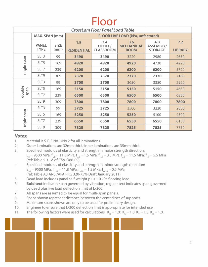
Notes: 1. Material is S-P-F No.1/No.2 for all laminations. 2. Outer laminations are 32mm thick; inner laminations are 35mm thick. 3. Specifi ed modulus of elasticity and strength in major strength direction: E0 = 9500 MPa; fb,0 = 11.8 MPa; fv,0 = 1.5 MPa; fvr,0 = 0.5 MPa; fc,0 = 11.5 MPa; ft,0 = 5.5 MPa (ref: Table 5.3.1A of CSA-O86-09). 4. Specifi ed modulus of elasticity and strength in minor strength direction: E90 = 9500 MPa; fb,90 = 11.8 MPa; fv,90 = 1.5 MPa; fvr,90 = 0.5 MPa; (ref: Table A3 ANSI/APA PRG 320-75% Draft January 2011). 5. Dead load includes panel self-weight plus 1.0 kPa fl ooring load. 6. Bold text indicates span governed by vibration; regular text indicates span governed by dead plus live load defl ection limit of L/300. 7. All spans are assumed to be equal for multi-span panels. 8. Spans shown represent distance between the centerlines of supports. 9. Maximum spans shown are only to be used for preliminary design. 10. Engineer to ensure that L/300 defl ection limit is appropriate for intended use. 11. The following factors were used for calculations: KD = 1.0; KS = 1.0; KT = 1.0; KH = 1.0.
CrossLam Floor Panel Load TableMAX. SPAN (mm) FLOOR LIVE LOAD (kPa, unfactored)
PANEL TYPE
SIZE (mm)
1.9
RESIDENTIAL
2.4OFFICE/
CLASSROOM
3.6MECHANICAL
ROOM
4.8ASSEMBLY/STORAGE
7.2
LIBRARY
SLT3 99 3490 3490 3220 2980 2650
SLT5 169 4920 4920 4920 4730 4220
SLT7 239 6200 6200 6200 6200 5720
SLT9 309 7370 7370 7370 7370 7180
SLT3 99 3700 3700 3650 3350 2920
SLT5 169 5150 5150 5150 5150 4650
SLT7 239 6500 6500 6500 6500 6350
SLT9 309 7800 7800 7800 7800 7800SLT3 99 3725 3725 3500 3220 2850
SLT5 169 5250 5250 5250 5100 4500
SLT7 239 6550 6550 6550 6550 6150
SLT9 309 7825 7825 7825 7825 7750trip
le s
pan
doub
le s
pan
sing
le s
pan
5
Floor
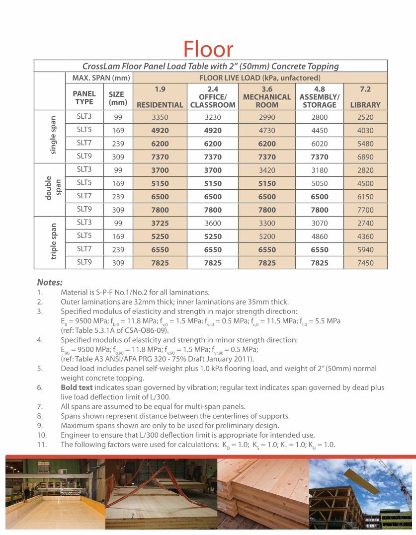
CrossLam Floor Panel Load Table with 2” (50mm) Concrete ToppingMAX. SPAN (mm) FLOOR LIVE LOAD (kPa, unfactored)
PANEL TYPE
SIZE (mm)
1.9
RESIDENTIAL
2.4OFFICE/
CLASSROOM
3.6MECHANICAL
ROOM
4.8ASSEMBLY/
STORAGE
7.2
LIBRARYSLT3 99 3350 3230 2990 2800 2520
SLT5 169 4920 4920 4730 4450 4030
SLT7 239 6200 6200 6200 6020 5480
SLT9 309 7370 7370 7370 7370 6890
SLT3 99 3700 3700 3420 3180 2820
SLT5 169 5150 5150 5150 5050 4500
SLT7 239 6500 6500 6500 6500 6150
SLT9 309 7800 7800 7800 7800 7700
SLT3 99 3725 3600 3300 3070 2740
SLT5 169 5250 5250 5200 4860 4360
SLT7 239 6550 6550 6550 6550 5940
SLT9 309 7825 7825 7825 7825 7450
Notes: 1. Material is S-P-F No.1/No.2 for all laminations. 2. Outer laminations are 32mm thick; inner laminations are 35mm thick. 3. Specified modulus of elasticity and strength in major strength direction: E0 = 9500 MPa; fb,0 = 11.8 MPa; fv,0 = 1.5 MPa; fvr,0 = 0.5 MPa; fc,0 = 11.5 MPa; ft,0 = 5.5 MPa (ref: Table 5.3.1A of CSA-O86-09). 4. Specified modulus of elasticity and strength in minor strength direction: E90 = 9500 MPa; fb,90 = 11.8 MPa; fv,90 = 1.5 MPa; fvr,90 = 0.5 MPa; (ref: Table A3 ANSI/APA PRG 320 - 75% Draft January 2011). 5. Dead load includes panel self-weight plus 1.0 kPa flooring load, and weight of 2” (50mm) normal weight concrete topping. 6. Bold text indicates span governed by vibration; regular text indicates span governed by dead plus live load deflection limit of L/300. 7. All spans are assumed to be equal for multi-span panels. 8. Spans shown represent distance between the centerlines of supports. 9. Maximum spans shown are only to be used for preliminary design. 10. Engineer to ensure that L/300 deflection limit is appropriate for intended use. 11. The following factors were used for calculations: KD = 1.0; KS = 1.0; KT = 1.0; KH = 1.0.
trip
le s
pan
doub
le s
pan
sing
le s
pan
Floor

CrossLam Wall Panel Load Table (Axial Loading Only)Panel
d (mm)
SLT3
99
SLT5
169
SLT7
239
SLT9
309 L (m) Pr (kN/m)
2.0 385 699 949 1179
2.5 332 650 904 1134
3.0 276 599 861 1093
3.5 223 547 818 1054
4.0 178 494 773 1014
4.5 143 442 728 975
5.0 114 392 681 934
5.5 345 633 893
6.0 303 587 851
6.5 265 541 808
7.0 232 496 764
7.5 203 454 721
8.0 177 415 678
8.5 378 637
9.0 344 596
Notes: 1. Pr = Φ Fcb A Kzc KC 2. Material is S-P-F No.1/No.2 for all laminations. 3. Outer laminations are 32mm thick; inner laminations are 35mm thick. 4. Specified modulus of elasticity and strength in major strength direction: E0 = 9500 Mpa; fb,0 = 11.8 Mpa; fv,0 = 1.5 Mpa; fvr,0 = 0.5 Mpa; fc,0 = 11.5 Mpa; ft,0 = 5.5 Mpa (ref: Table 5.3.1A of CSA 086-09). 5. Specified modulus of elasticity and strength in minor strength direction: E90 = 9500 Mpa; fb,90 = 11.8 Mpa; fv,90 = 1.5 Mpa; fvr,90 = 0.5 Mpa (ref: Table A3 ANSI/APA PRG 320-75% Draft January 2011). 6. Wind load has not been included. 7. Where the Pr values are not given, the slenderness ratio exceeds 50 (maximum permitted; CSA 086-09). 8. The following factors were used for calculations: KD=0.65; KS=1.0; KT=1.0; KH=1.0; Ke=1.0. 9. Eccentricity of axial load has not been included. 10. These values are to be used for preliminary design only. 7
Wall
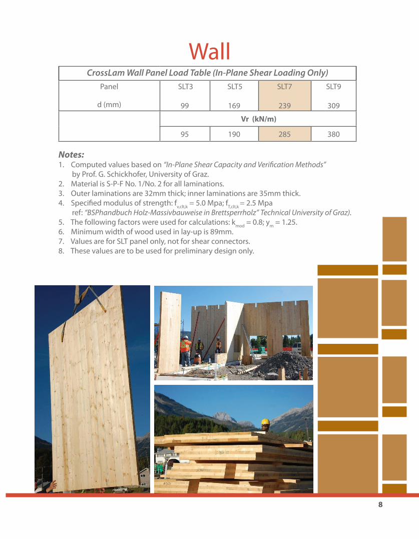
CrossLam Wall Panel Load Table (In-Plane Shear Loading Only)Panel
d (mm)
SLT3
99
SLT5
169
SLT7
239
SLT9
309
Vr (kN/m)
95 190 285 380
Notes: 1. Computed values based on “In-Plane Shear Capacity and Veri� cation Methods” by Prof. G. Schickhofer, University of Graz. 2. Material is S-P-F No. 1/No. 2 for all laminations. 3. Outer laminations are 32mm thick; inner laminations are 35mm thick. 4. Specifi ed modulus of strength: fv,clt,k = 5.0 Mpa; fT,clt,k = 2.5 Mpa ref: “BSPhandbuch Holz-Massivbauweise in Brettsperrholz” Technical University of Graz). 5. The following factors were used for calculations: kmod = 0.8; ym = 1.25. 6. Minimum width of wood used in lay-up is 89mm. 7. Values are for SLT panel only, not for shear connectors. 8. These values are to be used for preliminary design only.
8
Wall
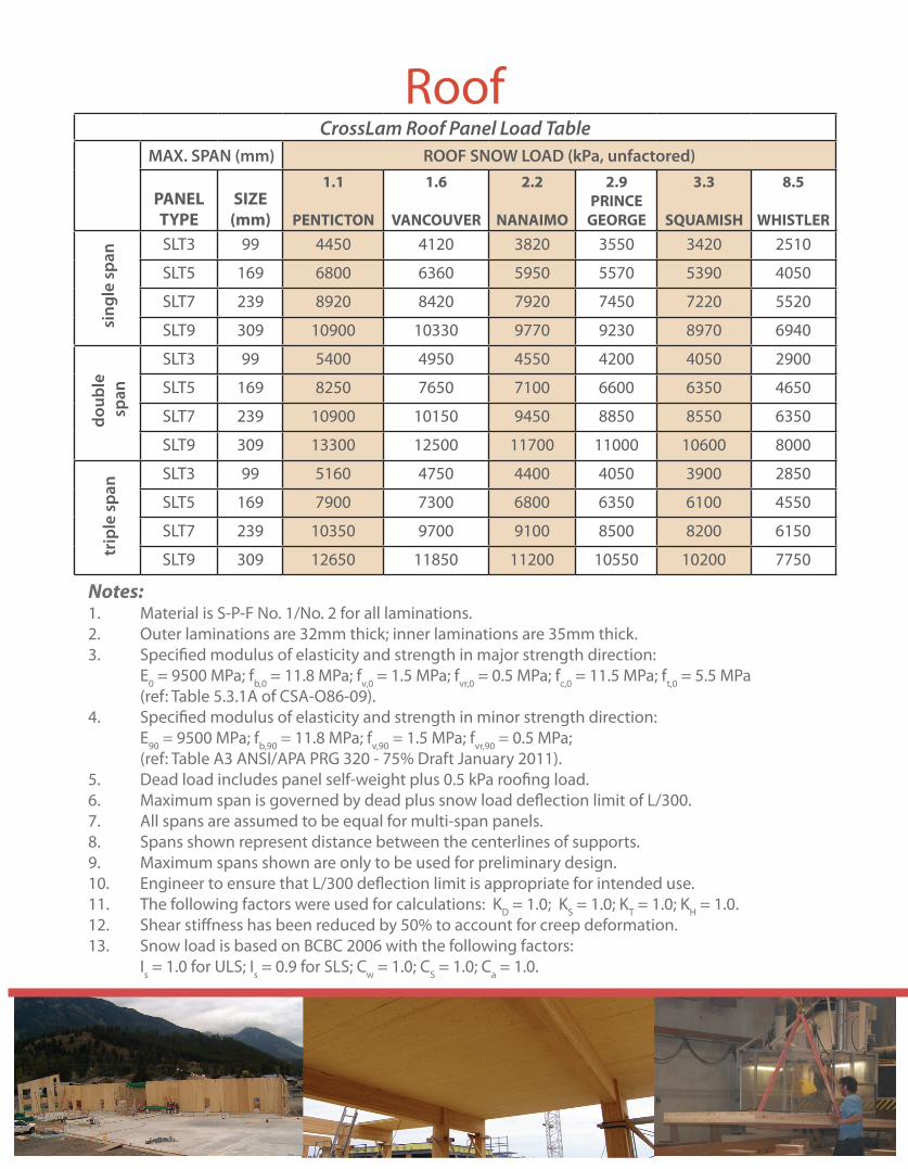
Notes: 1. Material is S-P-F No. 1/No. 2 for all laminations. 2. Outer laminations are 32mm thick; inner laminations are 35mm thick. 3. Specified modulus of elasticity and strength in major strength direction: E0 = 9500 MPa; fb,0 = 11.8 MPa; fv,0 = 1.5 MPa; fvr,0 = 0.5 MPa; fc,0 = 11.5 MPa; ft,0 = 5.5 MPa (ref: Table 5.3.1A of CSA-O86-09). 4. Specified modulus of elasticity and strength in minor strength direction: E90 = 9500 MPa; fb,90 = 11.8 MPa; fv,90 = 1.5 MPa; fvr,90 = 0.5 MPa; (ref: Table A3 ANSI/APA PRG 320 - 75% Draft January 2011). 5. Dead load includes panel self-weight plus 0.5 kPa roofing load. 6. Maximum span is governed by dead plus snow load deflection limit of L/300. 7. All spans are assumed to be equal for multi-span panels. 8. Spans shown represent distance between the centerlines of supports. 9. Maximum spans shown are only to be used for preliminary design. 10. Engineer to ensure that L/300 deflection limit is appropriate for intended use. 11. The following factors were used for calculations: KD = 1.0; KS = 1.0; KT = 1.0; KH = 1.0. 12. Shear stiffness has been reduced by 50% to account for creep deformation. 13. Snow load is based on BCBC 2006 with the following factors: Is = 1.0 for ULS; Is = 0.9 for SLS; Cw = 1.0; CS = 1.0; Ca = 1.0.
CrossLam Roof Panel Load TableMAX. SPAN (mm) ROOF SNOW LOAD (kPa, unfactored)
PANEL TYPE
SIZE(mm)
1.1
PENTICTON
1.6
VANCOUVER
2.2
NANAIMO
2.9PRINCE
GEORGE
3.3
SQUAMISH
8.5
WHISTLERSLT3 99 4450 4120 3820 3550 3420 2510
SLT5 169 6800 6360 5950 5570 5390 4050
SLT7 239 8920 8420 7920 7450 7220 5520
SLT9 309 10900 10330 9770 9230 8970 6940
SLT3 99 5400 4950 4550 4200 4050 2900
SLT5 169 8250 7650 7100 6600 6350 4650
SLT7 239 10900 10150 9450 8850 8550 6350
SLT9 309 13300 12500 11700 11000 10600 8000
SLT3 99 5160 4750 4400 4050 3900 2850
SLT5 169 7900 7300 6800 6350 6100 4550
SLT7 239 10350 9700 9100 8500 8200 6150
SLT9 309 12650 11850 11200 10550 10200 7750trip
le s
pan
doub
le s
pan
sing
le s
pan
Roof
For more information please contact us.
www.structurlam.com
BC Interior, AB, MB, SK Pacifi c Canada & Eastern Canada & International Dave Gardner Colin Chornohus, AScT. 2176 Government St. 200-9292 200th St. Penticton, BC Langley, BC Canada V2A 8B5 Canada V1M 3A6 t: 250 492 8912 t: 604 455 0709 f: 250 492 8906 f: 604 882 7300 e: [email protected] e: [email protected]
Ontario, Quebec, Atlantic Canada USAPatrick Chouinard Kris Spickler, P.E.371 Front Street W., Suite 237 4120 Douglas Blvd. #306-502Toronto, ON Granite Bay, CACanada M5K 3S8 USA 95746 t: 647-467-6070 t: 916 797 5588 e: [email protected] f: 866 801 1654 e: [email protected]


