
CRITICAL IMPACT POINTS FOR
CRASH TESTING TRANSITIONS
Submitted by
Ronald K. Faller, Ph.D. , P.E. Resea rch Ass istant Professor
Dean L. Sicking, Ph.D. , P.E. Associate Professor and MwRSF Director
MIDWEST ROADSIDE SAFETY FACILITY lJ nivers ity 0 f Nebraska-Lincoln 1901 "Y" Street, Building "C"
Lincoln , Nebraska 68588-0601 (402) 472-6864
Submitted to
Charl es F. Mc Devitt, P.E. Proj ec t Manager ancl Research Structural Engineer
FEDERAL HlGHW A Y ADMINTSTRA nON Turncr- Fairbank Ili ghway Research Center
Safe ty Design Divis ion (HSR-20) 6300 Georgetown Pike
Mc Lean, Virgipia 22 101 -2296
MwRS F Research Report No. TRP-03-84-99
April 16, 1999

Technical Repol't Documentation Page I. Report No. 2. 3. Recipient 's Access ion No.
DTFI-161-98- P-00287 4. Ti lic ,mel Suill ill e 5. Report DOllc
Critica l Impact Points For Crash Testing Transitions April 16, 1999
6.
7. Author(s) 8. Pcrlorming Organization Report No.
Faller, R.K. and Sicking, D.L. TRP-03-84-99
9. PerlilJ"llling Orgillli z,llillil NllIllC and Ad<l rcss 10. ProjeclfJ"ask/Wllrk Uni t No.
Midwest Roadside Safety Faci li ty (MwRSF) Uni versity of Nebraska-Lincoln
1 I. Conlmel rD or Uranl (G) No. 190 I Y St., Bldg. C Lincoln, NE 68588-060 I DTFI-161-98-P-00287
12. Sponsoring Org,miz<lli()Jl N,llllC and Address 13. Type of t{eport and Perio(J Cove red
Federal Highway Adm inistration Draft Report 1998-1999 Turner-Fairbank Highway Researc h Center Safety Design Division (I-iSR-20) 14 . Sponsorin g Agency Code
6300 Georgetown Pike McLean, Virgin ia 22 101-2296
IS. Sllpplclllclllnry Notcs
Prepared in cooperation with U.S. Department of Transportation, Federal Highway Administration
16. Allslrael (Limil : 200 words)
Two approach guardra i I transitions were modeled with BARRIER VII in order to determ ine the critical impact poin t (CIP) for each system. The computer simulation modeling was performed according to the TL-3 impact conditions fo und in NC HRP Report No. 350 (2). The first transition system consisted of a nested W-beam rail with attached rubrail and was supported by steel wide-nanged posts. For the nested W-beam system, the CI I' was determined to occur lor an impact I ,905-mm upstream from the centerl ine of the steel space tube. The second trans ition consisted ofa nested thrie beam rail with a backup steel tube member wh ich was supported by stee l wide-Hanged posts and inc luded a special post spacing. For the nested thrie beam system, the CIP was determ ined to occur lor an impact between post nos. I and 2.
17. Doeulllcnl Analysis/l)eseriplOl'S 1 M. A v,lilahil il y Sialclllcnl
Highway Sa fety, Guardrai l Roadside Appurtenances, No restrictions. Document ava ilable from: Longitudina l Barricr, Computer Simulation, National Technica l Informat ion Services, Approach Guardra il Transit ion 13arrier V II Springfie ld, Virginia 22 16 1
19. Se(,;urity Class (lhis rcpnrl) 20. Se(,;uri ty Class (lhi s Jwge ) 2 1. No. or Pages 22. Prke
lJ nclassilied I J nclassi li ed 39

DISCLAIMf<:R STATf<:Mf<:NT
The contents of thi s repo rt re tlect the views of the authors who are responsible for the facts
and the acc uracy of the data presented herein. The contents do not necessaril y reflect the offi cial
views or pol icies of the Federal I-J ighway Adm inistration. This report does not constitute a standard,
specifica ti on, or regulation.
II

ACKNOWLEDGMENTS
The authors wish to ack nowledge severa l sources that made a contri bution to thi s pro ject: ( I)
the Federa ll-li ghway Admini stra ti on for funding this resea rch e ffort ; and (2) Charli e Mc Devitt , P.E.,
Proj ect Manage r, fo r all hi s va luable input and support in suppl ying background information for this
pro ject.
III
TA BLE OF CONTENTS Page
TECHN ICA L REPORT DOCU MENTATION PAGE .... . ... . ... . . . . . ... . ...... . ..... I
DISCLAIMER STATEMENT ............. .... . ...... . ..... . ...... . ......... . .. ii
ACKNOWLEDGMENTS ........ . ....... .. ... ... . .. ......... .. ... .. . ... . .... . . iii
TABLE Of' CONTENTS ................................... . ............ . .. . ... IV
L ist of Figures ........ . ........... . ...... ..... . ....................•.... V
List of Tables ...... . .. . . .. . .. . . . ... . . .... . ..... . ........... ... ...•..... vi
I INTRODUCTION ...... . . .... . ................ . ............... . ...... . ..•... I 1.1 Background ..... . . . . . . ..... . ........... . ..... . .... . . ... . ...... . ..... I 1.2 Objecti ve .... . .. . ... . ....... . . ..... . .... . ..... . .. . . .... . ... . ........ 2 1.3 Scope .....................................................•........ 3
2 DES IGN DET'AILS - NESTED W-BEM~ TRANS ITION .... . ....................... 4
3 COMPUTER SIMULATION - NESTED W-BEAM TRANSITION .... . . .. . • .. ..... . .. 7
4 DES IGN DETAILS - NESTED TI-IRIE BEAM TRANSITION .... . .... . ......... .. ... 9
5 COM PUTER SIMULATION - NESTED TI-IRlE BEAM TRANSITION ..... . ......... 16
(i SUMMAR Y AN D CONCLUS IONS . . . . .... . ................................ . .. 18
7 REf'ERENCES .. . ..... . ...................... . ..... . . .... . . . ..... . . .... . ... 19
8 APPENDICES ....................................................... . ..... 20 APPENDIX A - BARRIER VII COMPUTER MODELS - BARRIER AND VEHI CLE ..... ....... .... . ............................... . .. ... . ....... . ...... 21
A PPENDIX 13 - TY PI CA L BARRII~R VII INPUT DATA - NWRR5.DAT AND NWRR5M.DAT ................................................. . ...... 25 APPENDIX C - COM PUTER SIMULATION RESULTS - NESTED W-BEAM TRANS ITION .. . .............. . ......... ...... . ........... . ...... . .. . . 30 APPENDIX D -BARR IER VII COMPUTER MODEL - BARRIER ..... .. ....... 33 APPENDIX E - TYPICA L BARRIER VII INPUT DATA - NEBT2RUN I B2N. DAT .35 APPEN DIX f' - COM PUTER SIMULATION RESULTS - NESTED THRlE BEAM TRANS ITION ......................................... . .. . ... . ........ 38
IV

List of Figures Page
I. Layout and Des ign Details lo r Nested W-[1eam Transition . . . . . .. . ... . . . .... . . . ...... 5 2. Design Deta il s fo r Nested W- Ileam Transi ti on (Co ntinued) ..... . .. ... .. .. . .... . ... . .. 6 3. Layo ut and Des ign Details lo r Nested Thrie Beam Trans ition . . ..... . ... . ... . . . .. . . .. 10 4 . Des ign Detai Is for Nested T hrie Beam Trans ition (Continued) ...... . ..... . ..... . .... II 5. Des ign Details li) r Nested Thrie Ileam T ransition (Continued) ....... . ............... 12 6. Des ign Detail s lo r Nested 'fhri e Beam Transition (Co ntinued) .. . . ... , ....... . . ...... 13 7. Post Detail s lor Nested Th ri c 11eam Trans ition ............... , . . , , ... , , ... . .. .. , .. 14 8. Concrete Bull ress Detail s for Nested Thrie Beam Transiti on .. . , . .. , , . .. , , .. . . .. . .... 15
v

List of T ables Page
C- I . Computer Si mulation Test Matrix and Results for Nested W-Beam Transition without Crushable Spacer Tube . ........................................ .... .... . .... .. 3 1 C-2. Computer S imul ati on Test Matri x and Result s for Nested W-Beam Transition with Crushable Spacer Tube ................... . .. . ............................ . ........ . .... 32 F-I . Computer S imul ation Test Matri x and Results for Nested Thrie Beam Transition w ith Backup Tube Rai l ...... .... .... . . ... . ......... . ........ . ..... .. ... ...... .. .. ..... . 39
VI

I INTRODUCTION
1.1 Background
Approach guardrai l transitions are commonl y used to provide structura l con tinuity between
a Aex ible guardrail system adjacen t to the roadway and a rigid rai ling system located at the edge of
a brid ge deck. Typica ll y, approach guardrai l transitions are des igned to incorporate a gradual
increase in latera l stiffness in order to reduce the potent ia l for an im pacting vehicle to snag or pocket
near the end of the bridge ra iling. In the past, the increase in latera l stiffness has been accomplished
by inco rpora ting one or more of several acceptable methods. Common methods fo r increas ing the
lateral sti ffness include prov id ing a reduced post spac ing, lengthening the posts in order to increase
embedment de pt h and post-so i I lorces, usi ng thri e beam rail in place of W -beam rai I, a nd nest ing the
guardrai I beams. Rubrai Is, typ ica ll y consisti ng of either a stee l channe l or W -beam rail placed below
the mai n ra il, a lso have been used to eliminate the potenti al fo r whee l snaggi ng on the upstream end
of a rigid bridge ra iling.
S i nce the mid-1980's, several resea rch studies were conducted to develop, crash test, and
eva luate trans ition des igns that incorpornted the common strengthening techniques. As a result of
these cras h test programs that were large ly based on crash tests with passenger sedans, several
trans ition des igns were found to be acceptable accordi ng to the eva luati on cri teri a found in the
Nati ona l Cooperati ve Highway Research Program (NCHRP) Repo rt No. 230 Recommended
f'ro cedures/iJrthe Safely I'er/imnance Evaluation of l-lighway Appurtenances (1). T hese criteri a
required that the trans ition system perform acceptab ly when crash tested with a 2,04 1- lb sedan
impacting at ,\ speed 01'96. 56 km/hr and an ang le 01' 25 degrees. The im pact location for thi s crash
test was specified to be 4,572-l11m IIpstream frolll the second sys tem or bridge rai ling.

In 1993 , NCHRP published Report No . 350 Recommended Procedures f i)r the Sa/ely
l'er/iJrmance Eva/ua/ion ,,{Highway Fea/llres which included rev ised crash test procedures and
eval uat ion criteri a for approach guardrai l transitions (2.). Due to the recent increase in popu larity of
li ght trucks and sport utility ve hi cles, the sedan test veh icle was replaced w ith a 'It-ton pickup truck
hav ing a mass o f 2,000 kg. Although the impact angle remained the same, the impact speed
increased li'om 96.56 km/hr to 100 km/hr. In addition , the impact location is now to be determined
as the predi cted worst case locati on referred to as the criti ca l impact point (C IP). Genera l guidelines
for determining C IP 's are provided in NC HRP 350 in the form of graphica l charts and tab les.
However, it is recommended that the C I P be determined by performin g computer s imulation
model i ng or the spec ifi c approach guardrai I transition system. The most common computer program
used in the anal ys is and design of approach guardrail transitions is the 2-dimensiona l, dynamic
nonlinear finit e-c lement code ca ll ed BARR IER VII elJ
Following the adopt ion of the NC I-IRP 350 guidelines by the Federa l Highway
Ad mini stratio n (F I-TWA), State Highway Agenc ies will soon be required to use transition des igns
that meet NCHRP 350 sa fety standards. Theref'o re, existing transition des igns prev iously crashed
tested w ith sedans according to NCHRP 230 gu idelines must be re-eva luated lIsing pickup truck
crash tests accordi ng to the new NCHRP 350 impact standards.
T.2 Ob.icctivc
The objective of thi s rcscarch project was to determine the C IP for two approach guardra il
transition des igns that will be later crash tested using the Test Level 3 (TL-3) impact conditi ons of
NCHRP 350. The lirst transition system, consisting or a nested W-beam upper r,lil and a lower
rubrail , is suppo rt ed by stee l posts with a redu ced post spac ing. This transition des ign is attac hed to
2

a sa fety shape concrete bridge railing. The second transition system, consisting of a nested thrie
beam rail and a backup steel tu bel, is supported by stee l posts with a spec ial post spacing. Th is
transiti on system is attached to a concrete buttress w ith a nared end section .
1.3 Scope
The scope of thi s project was com pleted by performing a seri es of computer simulation runs
wi th BARRIER VII to ide ntify the C IP along the length of each transition section. Fina ll y, the
simulation resu lts were ana lyzed, evaluated, and doc.umented.
3

2 DESIGN DETAILS - NESTED W-BEAM TRANSITION
The lirst transition system, shown in Figures I and 2, consisted of an upper rail and a lower
rubrail in the transition region. The upper rai l was constructed with nested , 12-gauge W-beal11 and
single 12-gauge W-beam, while the lower rubrail was fabricated from two different rail s izes - a
C152x 12.2 channe l rail and a special bent plate rail sect ion. The guardrai l in the transition region
was supported by Iwo sizes ofwide-tlange sleel posts. Post nos. I and 2 were W203x 19.3 by 2,286-
111111 long, while post nos. 3 through 9 were W152x 13.4 by 1,98 1-111 111 long. The post spacing,
starting at the upstreal11 end of the concrete bridge railing, consisted of one at approximate ly 302
111111, four at 476 111111 , and fo ur at 952mm. A schedule 40, 250-111111 long structural steel spacer tube
with a 168.3-111 111 outs ide dial11eter, was placed behind the nested W-beal11 rail and on the face of the
concrete end sec tion. The tra nsition des ign was attached to a sa fety shape concrete bridge railing.
4

• \
JOO
50 102 101
0 -o
-!- -G o
Steel DICIt, -/6 1M! tfllc!roeJS
BEARING PLATE
....... 28 mill d/o. holes "rp..1
WOOD BLOCKS FOR RUBRAIL
POST HCI(NfSS THICKNESS
Sl~ lSl1(ll;t r lube See SltJfIdord 11611-29.
:. '. 180 , 100 mill
OIOc:t See !(J0It for tllictness. - - -
\ Wood Ob;t(ltJ1 ~ Drcwlf1(7 NJRR-l
Two nested ... /letlIII roll 'lemen/s
Single be'" plale (till Ueonetll for fWroli
J,l0 or fla" er
Sleel pru/& t PW£OlJ tiM Wood block ............... IP()BOI-mot/lfledl ---. lPost f.!)tftcuOll 91
"'" "'" SECTON A-A SECTKJN A' -A'
L:.· :: .. ::
ISS 140 ". ., .. " lWfJ nested If tIeOIII foil t~fI'J
<T, 1122 . 6 J50 mm H.$. Itt , IJOIIs wll" ~
beor'f1(7 oIole or "f! ~ I' . ' I CoIter!!: l !!: Inser t OfICftOr csnlfl/llr. 1IIIn.
, ': . ... . :',
SI IJ'tI S(K1cer 11A>e, $clledlJ/e 40 ""/vOn/red pice. 168.3 00 , 250 mill 10119
r A•
I L-A,
...,... go , I
<T'
I r-S
L-s
• I I
I'. -~ J t_ 051 # 11.1 flNolf
See "'_'(19 NJRft-2 ~- ...... -
PosIS I tll'Id 2 (Jr, $lt!eI poSts "'200 , f9 - 2190 obtIp.
<T,
SEeTON 8-8
<T, '" I I
FOCl6 " 75 Carr/age
Bent plett ''''011 tJdt (Fidd drill flofl98J
~ Orowl"'l NJRR-2
PLAN PDf Utlll/s COIII'IeCIIOf'I 10 S'flX:/UI'e
FB80J guardrail tJoIl and "cess fltJl
'SJ
...,if" tJ reclfUlouf,,, pIote wosher urtder tile .
SECTION C-C
'"
boll /te<tJd tJl>d tJ Slftl OO'OSl!er under IIIe flIII. -~ Boci -CJtl p/ore -
I I i I I ( .:.~ .:...:.\
Beflf p/(Jle ftlbroll
.. \ ,
\O~
I E6f}I: of pt/'I~nt OF grOUltd 11M al (au of folf as oPfl/ICI1b1e.
~ MI6 corr. tJd/ wflll fNJ/ or.d WD$fler Ilyp..J.
. , .
ELEVATI)N
rl
•
NO SCALE
NOTE:
1. Offsel dflU 011 addillantll lillie an &lNIS 1 Iflr/llJfJlt 6 la all(JC1I III'OOd tt.focts far rubfo/l olldlor Ifle r!lOroll.
J. Offsel drln ~ O/(ds far fwoil /0 sll S(MJtelr an Ifle poSl floflt}f: an posls 1 Iflr~fI 4. ~~ lIIOCts to poS ts 2 arid 4. Secure futJfOl1 aM O/oc;ts to JX)$I fkJnge on posls I. J. and 5 use MI6 carrloge bolls.
4. 011 fl()t (JOII II' Oeoll! 10 JX)$IS and l>/octs 0/ posts 2 IIIfClVlJft 4.
5. RrlnfarCed COIICff/e 00'0" ar ;"'1. pt1fopel fl'VSl Oe capoOle of de~eJooif19 a 265 iN pUll /lUI "relttJffl.
6. Fllfll lsfl tltJf(/WfJft In tile 1Rtf(1t; sItes sflown. E.~'OJefll IlI!tIeflol s l leS ""'y /:. used IrlIeII l1It:/rk s l m tIf, (JOt o"oikJO/a.
"J
PrJr U",lrs Guordfoll
I 5"". G4
J
WETRIC DRAWING
G4 BEAt.! GUARDRAIL CONNECTION TO STRUCTURE
SAFETY SHAPE FACE STEEL POS TS
' L. __________________________________________________________________________________________________________________________________________ l-·_-·_·~.=':."'~ ______________ JL~N~J~R~RC·~I.J
Figure 1. Layout and Design Details for Nested W-Beam Transition

I
/0
CUI (/an()t. bend ond weld fU shatrn. \
~ .\
PLAN
FRONT SIDE
WOOD BLaCKOUT FOR RUBRAIL AT WALL
- SD/Iu bell skils r Steel plole 290 mm
I 125, 20 $ 2S 1M! "YD.' I wid'" by J.41 111m 'Metness Po$I bell slots
:::: ~ j I "'I f ..-L-_,_ ,/ t
20 .. 6S 111m lirA ) ~l
~l • ~-, - ~~ - - - .~ - - --- - - -- - - -- - - "- -d ._.
.... 1 so l~ 11 475 ' 1425 ,so ~ ~
lmJ ELEvArON
BENT PLATE RUBRAIL
CuI f/OflQll! . belld ond Wf!:/d liS shawn.
PLAN
Bend ,- Drill IJ mm d/o.
_ Drill 20 !11m dia. hole (lyo.J
IIoJe (lyp.) ..... ~ ~~f------------o,. c
·~-'--LL-----_;;:+T----·'-, ~" '" T ~ MW r- i -i L.ll..
4J7 ; ~
ELEVATKJN
CISO X 12.2 RUBRAIL
- - - .6-- _ .. ~T~ -'--"'-
FRONT WOOD BLaCKOUT FOR RUBRAlL AT POSTS
\\'-Sea., rcil-
W('oCl(t blocL I poaol - n»1if ;e-1 1
PLAN POST AND BLOCK
EXPLODED VIEW fRail and w')SfY" wo' $/Q..'nl
1V001 Noel (F08()! tn(y11fi"(jl
refY.lJ 9(1<1'0(01/ {YIII wUn fio/:ess"'{j IJJI
NOTE,
2. OIrrcM/oI'IfJ' '*"'fICeS IlOl $_ or ,mplle6 fire In/elided /0 Oe IllOSe COIU/s/eflf witll ,~ prooer ruocl/otl/nfJ of 1M pari, lrodudlnfl lis fJPtJeorortCt, and occepttfj tfltJfllJfOCllXl1I9 Pf'IXliccs.
"~[[ ,:, @ - ~ '" I I I
1~ 30 I
~ WOOD BLOCK
(PDBOI- MODIFIED) U.s"OI:'_TO€IIT rT '_11101
'£Cl(fI.u,. _n 1OW .. 1:TR1TOI
IoI£TRlC OR AII1NG
G~ W BEAll GUARDRAIL CONNECTION TO STRUCTURE
SAFETY SHAPE FACE RUBRAIL
NO SCALE • ~ • L-____________________________________________________________________________________________________________________ ~ __ ~.~"~"'~ __________ _l~N~J~R:R~-~'J STEEL POST AND BLOCK DET ML
Figure 2. Design Details for Nested W-Beam Transition (Continued)
:\ COMPUTER SIMULATION - NESTIW W-BEAM TRANSITION
3.1 Intl"Oduction
Compute r s imulati on model ing w ith BARRrER VTl CD was performed to ana lyze and predict
the dy namic perfo rmance of th c approach g uardra il transition systems prior to full -sca le vehicle
c rash testi ng. Computer s imula ti o n was a lso used to determine the criti cal impact po i nt (C rr) fo r the
nested W -beam approach guardrni I transition. Several s imulations were conducted model ing a 2000-
kg pickup truck impacting at a speed of 100.0 km/hr and at an ang le of25 degrees. T he BARRl ER
VII finit e e lement models of the approach g unrdra i I tra nsition systems as well as the idea li zed finite
e lement , 2-dimensio nal vehicl e model for the pickup truck a re s hown in Appendi x A. Typica l
comp ute r s imu lation input dat a lil es fo r the nested W-beam transitio n sys tem and pickup tru ck are
shown in Appendi x B.
3.2 Simulation Results
f'o urteen computer s imu la tio n runs were performed on two confi guratio ns of the nested W
beam approach g uardrail trans ition, as shown in Tables C- I and C-2 or Appendi x C. T he firs t seven
runs were conducted using a ri g id post suppo rt in place of the s tee l spacer tube. T he las t seven runs
were perfo rmed using a fl ex ible post suppo rt to represent the s tee l spacer tube. The s imulation
res ults indicated that the approach guarcirai I tra nsition system wo ul d sati s fac to ril y red irect the 2,000-
kg pickup tru ck. In addition , a ll struc tural hardware was predi cted to remai n func ti o nal during the
vehi c le impac t w ith the approac h guardrail transitio n system .
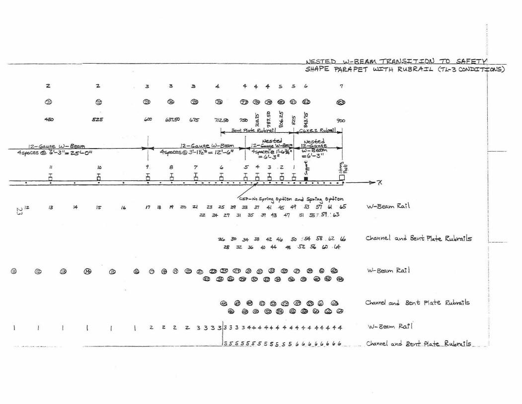
f'o llowing the analys is or the s imulatio n resu lts, the C IP was de te rmined to occur for a
p ick up truck im pacting 1,905-mmupstrcam o f the cente r! ine or the s tee l spacer tube. The max imum
dyn,ullic'lI1d pe rmanent set dellcc ti o ns of the upper W-hCHIll rail , as mCii sured from th e roadway
7

surface to the center of the ra il , were 133 mm and 94, respective ly. The max imum 0.0 I O-sec average
latera l and longitudinal dece lerati ons we re 13.6 and 13.3 g's , respectively. The peak 0 .050-sec
ave rage impact I()rce perpendicul ar to the approach guardrail transition was 282. 1 kN. The pickup
truck became para llel to the approach guardrail transition at 0.203 sec with a velocity of75.4 km/hr.
At 0.266 sec a lter impact, the pi ckup truck ex ited the approach guardrail trans ition w ith a ve locity
of 72 .2 km/hr and at an angle of 5.0 degrees.
8

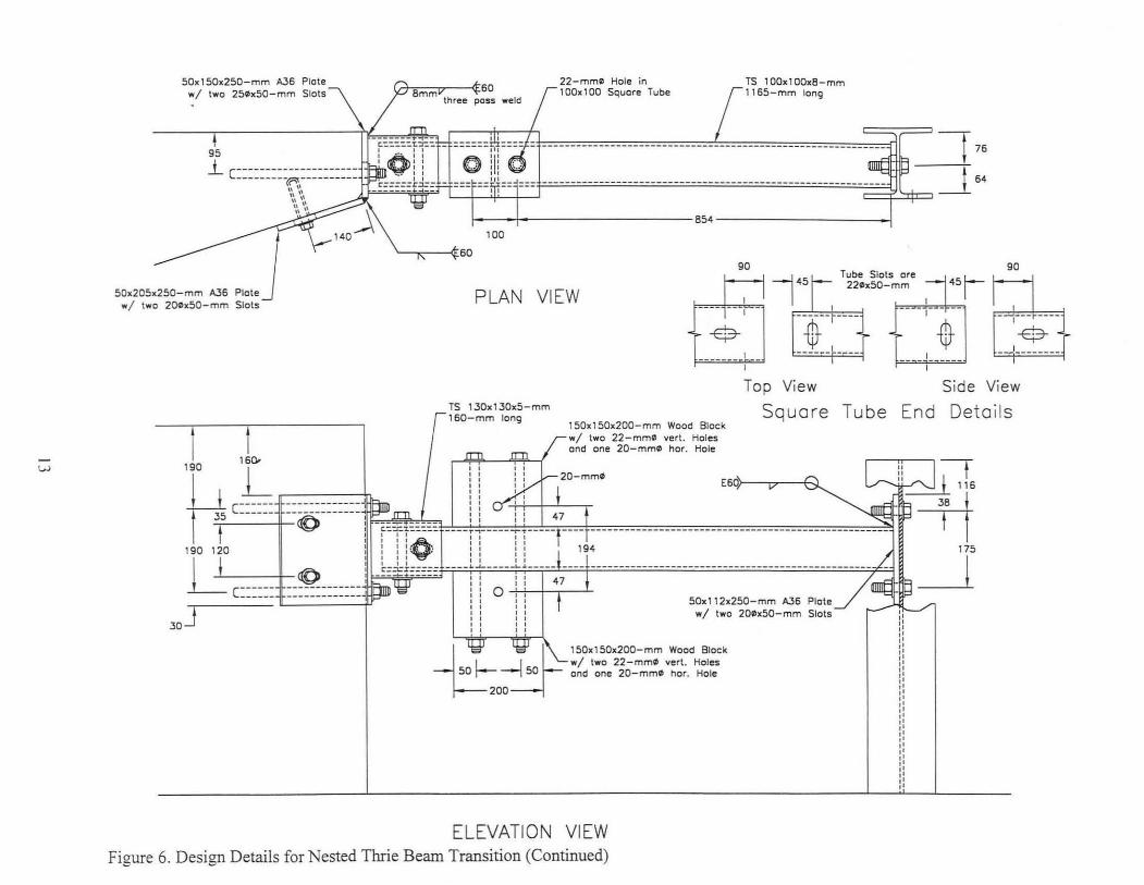
4 ImSIGN DI(T AILS - NESTEI) TIIRIE BEAM TI{ANSITION
The second transition system, shown in Figures 3 through 8, consisted of a thrie bea l11 rail
and a special tube backup rail in the trans ition region. The corruga ted rail was constructed with
nested, 12-gauge thrie beam which was 3,8 1 O-l11m long. The special backup rail , fa brica ted fro m
I 02- l11m x I ()2-ml11 x 7.9-ml11 i\STM /\500 ( irade J3 st ructural steel tubing, was posi tioned between
post no. I and the upstream end of the concrete buttress. Fabri ca ted steel hard ware was used at each
end of the tube l11ember to provide a rigid attachment. Timber blockouts were attached to the top and
bottom sur faces of the tube member to allow for a timber spacer to be used to block the rail away
from the tu be at a location of952-mm downstrea l11 of post no. 1. Thi s timber spacer and back up tl lbe
rai l combination was used to si mulate a guardrail pos t in the span were a post could not be installed
clue to the ex istcnce of the bridge substructure. The guardrail in the transition region was supported
by two sizes of wide-flange stee l posts. Post nos. I lind 2 were W 152x37.2 by 2,59 1-mmlong, while
post nos. 3 through 6 were W I 52x22 .3 by 2, I 34- l11m long. The post spacing, starting at the upstream
end of the concrete buttress, consisted of one at approx imately 296 mm, IQur at 952 mm, and one
at 1,905 mm . The transition design was attached to a concrete buttress whi ch can be used with either
safety shape, rectangul ar, or open concrete bridge rai ling systems.

0
9CT Posts in Founctolton Tubes • / Clound Line Strut a: 9CT Coble Anc:I'IOI'
12 \J
L ,zj_ •-• = · ~'" ----!- ------------------------ e sooc:cs o ~- - ~~•o -------------------------!
12- C...go ltvio 8oama, .1810 mm (1 2.5 ll)
'' ' ' ' ' '' ' ' '
i i '. ii Wl~7 (WSXZ~) S!ftl Pam 2591mm ~ J' }'
0
• 1 1 50a200:1.•~ 7 r lfTlbcf 9aockouls
Wl~ (W6a1!1) Sled Pos1 2134mm ton9 • /150a200z4S7 Totnber Bkac:l&out
WI!;Ox22 (Wfoal~) S! .. l Posl 213<mm lon9 • /150a200a457 r.mo.r BlockoJt
12 Coyg• w \o Thtie 8eam l rcMi\ion
'' '' '' '' '' '' '' '' ''
12 eo.go w-Beom Guora<oo1. 7520 mm (~ ll)
L_., .. ~- ... _ ~ •I 1SO.Z~ Timber Bktcllovt•
Figure 3. Layout and Design Details for Nested Thrie Beam Transition
12 Cougc w- Beom Cworotci. 7620 mm (n It)
' ' '' '' '' '' '' ' ' '' L.J

Thrie Beom Terminol Connector
/ Concrete Buttress
-, • • 0
• 835 • 0
, • I I 100
I
Nested 12-Gou e Thrie Beom .361 0 mm
Roil Height 804mm.....J.
~ 0 0
0 0 0
I JJ I I I 1 1 1 :
1 1 1 1 1 1 1 1
1 1 1 1 1 1 , , I , , I I , , I I , , , I , , , , , , , , , , ,
L,-' L,-'
0
0
I 1 : 1 1 1 1
1 1 1 , , , , , ,
I I L.J
12-Gou e W-Beom to Thrie Beom T ronsition Section
1905 mm
1 1 1 1 1 1 1 1 1 , , , , , , I , L ..J
12-Gou e W-Beom Guordroil, 1905 mm
Roil Height 706mm
0 -
1 1 1 1 1 1
1 1 , I , , , , , ,
L(
W1S0x37 (W6X2S) Steel Posts 2S91mm long =oJ W1S0x22 (W6xlS) Steel Posts 2 1.34mm w/ 1S0x200x356 Timber Blockouts
,oJ w/150x200x4S7 Timber Blockouts
W1S0x22 (W6xlS) Steel Post 2134mm long w/ 1S0x200)(4S7 Timber Blockout
W1SOx22 (W6x l S) Steel Post 2134mm long w/1 S0x200x457 Timber Blockout
Figure 4. Design Details for Nested Thrie Beam Transition (Continued)
0
1 1 1 1 1 , , I I I I I I
L(
Standard W-Beom Guardrail

IV
J50mm
" H Ii i1 "
" " H 11 Ii
Wekled 5O-mm Plate and lJO:o:1JO-mm
Square Tube Assembty
T. a 20..170-mm ASTW AlO7 He. Head Bolts wI Nuts and Washers
Two 20..4450-mm ASTW A.301 He" Head Bolts wI Nuts and Washers
15O,,200.400-mm long Wood Block
T.o 20.,,75-mm ASlIol AJ07 He. Head Boits . 1 Nuls. and Woshers
,.
T.o 16'.IOO-mm ASTM AJ07 He)! Head Bol\s wI WOShers 1------ 952.' - ----+ -----9" .' ------1
©c ©
© ©
©(
I
ond Concrete AnChors
24 .S
Two 16 •• 400-mm ASTIol AJ07 Cuardrai l BoI\ wI Recessed Nut
PLAN VIEW
-+1--- 6>0 ---1-1- 298-
Welded 500-mm Plate and lOO"'00-mm Squore Tube. ~
, ';0 = \-. t c------,
, '90 = \. 1 c=:: ,
,
--------0----
_Jl ____ -------
" " y- 20-mm' --~-- - ,
i! j-t
IF::~=""~;~;-~z+;~; J--·-·'.l9-... ~-----------·--}.,.:'i~ 1 11-:J£~!'f'~:J.~'-· ........ " --- - ---::O!':Jj, .. -'!..... ~1r~r Ul== -ii'V"
:::: 103 T.o 20-mm' Holes ..z.. L..,..-" II in Post Web - ~ 'it ... ;
Two 20-mm' Nub wI Weshers on Cost-in- Ptoce Rods
'- Chamfer Concrete Comer in formworlt
• • • • • • • • • • •
ELEVATION VIEW
Figure 5. Design Details for Nested Thrie Beam Transition (Continued)
-'" \ <0>
m ...., <0>
· • : • : : •
w
50ll:150ll:250-mm A.36 Plate wi twa 2SlhSO-mm Slots
95
G'f,8"'m~m~-~60 tnree pass weld
22-mmlO Hole in 100ll:100 Square Tube
TS 100ll:100ll:B-mm 1165-mm long
Gdlr-;;;JJ,-= __ = ___ = __ = ___ = __ = ___ = __ = ___ = __ = ___ = __ = __ L ___ = __ = ___ = __ = ___ = __ = ___ = __ = __ = ___ ",: __ ~ ___ X= --I 76
~ C=========~========= = '~, '::, lJF;;';;'~~iF .. " ':",
'---+--'t-----+----j=---=---=-- --=----=---=----=---=----=-- --=---=----=----=---=----=---~----~---~=:J 64
50ll: 20Sll:2S0-mm A36 wi two 20lhSO- mm
.J Slots
1 40~ ~---r----------------- 854---------------___ '00
'-----.-----<t 60 90
145 Tube Slats are
PLAN VIEW 221OlI:50-mm
, -$-
-~--I--- -
------ ----
451 - ,-
~ - '-
90
EE ,
TS 130ll:130ll:S-mm t160-mm long
Top View
Square Tube End
Side View
Detai ls
30
1S0ll:1S0ll:200-mm Wood Block wi two 22-mm~ vert. Holes and one 20-mm0 hor. Hole
,10 ,ll~ ~ ~ I : : ; l...- ~20-mmlO E6;W----".--+-~ U
I H ~ I ~ L.r-. ~ '16 L1 c-~ _____________ J ~ i i ....f-i I
I 3,5 ------ --~-------~ H, ~~-;rt:_lIJl--~_-~:_:_-~-_-_:~_ obW: :=U:=-d:d: d.:,4';.;.7=± t===========~"",~ ' 90 do ~ i" i EO, ----iT ---Tr---r -;r------ -- -------------------- ------------ -----
38 I
11 I I ((9 _bkh=::: ----lL--1L--L~L----- - ----- --- 5-0-,-,-,-2-,-2-5-0---m-m---.-:6--P--,O-\-e----~,....._-: - -~L-- T ~ c====== ======:======- ~~ "" e~ '~mm: ~ ~ J~r------ wi two 201OlI:50-mm Slots
ELEVATION
l S0ll:1S0ll:200-mm Wood Block wi two 22-mm0 vert. Holes and one 20-mm\ll nor. Hole
VIEW Figure 6. Design Details for Nested Thrie Beam Transition (Continued) - -

MIDSPAN RAIL SUPPORT Two 150x150x200 Timber Blocks Attoched
to 100xl00x8 Squore Tube wI 150x200x400 Timber Blockout
rr- ±~ I 753 ~ I 804 829
550
1 1381
l~ POST 3
W150x22 (W6X15) Steel Post 2134mm long wI 150x20Qx457 Timber Blackout
B04 B29
1838
POST 1 W150x37 (W6X25) Steel Posts 2591mm long
wI 150x20Qx457 Timber Blockouts
1355
l~ POST 4
W150x22 (W6x15) Steel Post 2134mm long wI 150x200x457 Timber Blockout
Figure 7. Post Details for Nested Thrie Beam Transition
1838
POST 2 W150x37 (W6X25) Steel Posts 2591mm long
wI 150x200x457 Timber Blockouts
72B
tv I I I 'I' I'- I t----'-V 706 72B
550
POSTS 5&:6
W150x22 (W6x15) Steel Posts 2134mm long wI , 50x200x356 Timber Blockouts

~"I ' 0 0 0 0 0
'" '" '" '" '" I I • •
350 190
L •
50-mm min. cover I;
! 50 mm min. cover
-:-- 13 1 100
- c- 13 100
- c- 13 100
- c- 13 100
- c- 13 100
550 - t-- 13 100
- t-- 13 75 13 13 13 13
- f-1
13 100
19 19
1->----600-----1
2230 0 0 0 0 0
'" '" '" '" '" -' I' -' I' -' I' -'1'-II II II II
200 II II
l II II II II II II
I
• Two 20-mmil by 355-mm long 316SH stoinless steel or ASTM A193 87 alloy threcded rods thot ore cost in piece.
~203~350==:j 1000 ' ------------~~------630------~
50-mm min. cover I
I
E;l ,lo E;l --- - -=:. --+
E;l 190
'" ---~ I 55
835 ..,
I
f---100
f-- -75
250
19 19 19 19 19 j
19 19 19
Figure 8. Concrete Buttress Details for Nested Thrie Beam Transition

5 COMPUTER SIM ULATION - NESTIW THRlE BEAM TR ANSITION
5.1 Introduction
Computer simulation modeling with BA RRIER VTl Q) was perfo rmed to analyze and predict
the dynamic performance of the approach guardrail transition systems prio r to full -scale vehicle
crash testing. CO l11puter simulati on was also used to determine the criti ca l impact point (CI P) for the
ncsted thrie benl11 approach gU'lrd rail tra nsit ion. Severnl simu lations wcre cond uctcd modcling a
2000-kg picku p truck im pacting at a speed of 100.0 km/hr and at an angle of 25 degrees. The
BARRIER VII linite element model of the approach guardrail transition system is shown in
Appendix D. A typical computer simulation input data fil e for the nested thrie beam transi tion
system and pick up truck are shown in Appendix E.
5.2 Simulation Ilcsults
Six computer simulation runs were performed on the nested thrie beam approach guardrail
transition, as shown in Table 17- 1 of Appendix F. The simulation results indicated that the approach
guardrail transit ion system would sati sfacto ril y redirect the 2,OOO-kg pickup truck.
Fo ll owing the ana lys is of the si mulation results, the CII' was determined to occur for a
pickup truck il11pacting 1,725-ml11 upstream of'the tapered concrete end section or at the midspan
location of' pos t nos. I and 2. The max imum dynamic and permanent set defl ections of the thrie
beam ra il , as measured from the roadway surface to the center of the ra il , were 170 mm and 141 ,
respecti ve ly. The max imum 0.0 I O-sec average lateral and longitudinal dece lerations were 12.5 and
13.3 g's, respec ti vely. The peak 0.050-sec average impact fo rce perpendicular to the approach
guardrail trnnsi ti on was 133.8 kN. The pi ckup truck became para llel to the approach guardrail
transi tion at 0. 193 sec with a veloci ty of 67.8 km/hr. At 0.325 sec after im pact, the pick up truck
16

exi ted the approach guard ra i I transition with a velocity of 64. 9 km/hr and at an angle of 13.3 degrees.
17

6 SUMMARY AND CONCLUSIONS
Two approach guardrail transitions were modeled with BARRIER V[J in order to determine
the CIP for each system. The computer s imulation modeling was performed according to the TL-3
impact conditions found in NC I-IRP Report No. 350 CD. For the nested W-beam system with
attached rubrail , the CIP was determined to occur for an impact 1,905-mm upstream fi·om the
centerline of the steel space tube. For the nested tluie beam system with attached backup steel tube,
the crp was determined to occur for an impact between post nos. I and 2.
18

7 HEFERENCES
I . Michie, .I . D., Recommended Procedures/or the Safety Per/brmance Eva/uat ion ()/Highway Appurtenances, Nati onal Cooperati ve Highway Research Program (NCHRP) Repo rt No. 230, Transportation Research Board , Washington, D.C. , March 1981.
2. Ross, I-I. E., Sicking, D.L. , Zimmer, R.A. and Michie,.l.D., Recommended Procedures/br the Safety I'erjbrmance Evaluation uj' High way Feature.\' , Nati ona l Cooperati ve Resea rch Program (NCJ-I RP) Repo rt No. 350, T ranspo rtation Research Board, Washington, D.C., 1993 .
3. Powell , U. I-I. , BARRIER V//: A Cumputer Program Fur Evaluation ojAutomobile Barrier Systems, Prepared /"01': Federal Highway Administration, ReportNo. FHWA RO-73-51, April 1973.
I ()

8 APPEN DI CES
20

APPENDIX A
BARRIER VII COMPUTER MODELS - BARRIER AND VEHICLE
2 1

B""", "'~ Tr(=' 2. z. Z. z. Z 2- .3
tbst' Me..m beY ,-.)1.I.y¥\~eYS ~ @ @J @ @; ® db @ Q3>
'Pose Loa:;.±ib'l"lS(iv\.) 0 75 ISO US 3«> 3 7S 450 57.5 (.CD 6
r 1 2.-~U.~~ L.!.kB.e!2!"'" ' I ~ 12 <OtuLGe. w- Br:em • I • 4spo-ces@'c'lL 3 1t= 2S'-01l 4sFc.es$ 't'-3 u,..z.sl-O" I 4<;
A~ POs-/:; N .... ",bers 17 J. JO f4. 13 IZ. II III 9
Q n is is is is is 9 f; '" ! . N
tJod<. ,>J~krs 2 3 + r. 7 B /0 " IZ. 13 14 /s- I. 17 18
®
2. Z
z
I Z-~u..~e. W-8
i _____________ _______________ ---"IJ.18""'Su.T=Eb----l6i-BEAM :n;SI\lSI"TIOA,) TO SAFETy;
.. " 3
szs !.37.SO t.7S 7/2.50
~<Zil>@®
l!l Iii ~ 7-'" ~ ~ t
. " '" «Ie. I
SI+I'tPE ?ileA PEl u="rl-\ RIJ,8RfT:n. C-n-3 CDN=TI:Q'JS)
7
4s,.,.= @, '-3 II,., z..st-O" 4-sr-=i1! I'--I.~· =4/-3"
I I ! I i~-'
==~~==z=~==~~~~~~~~.~;?~~.~i~.~~~.~~.2~~.~b.~.~.~.~~--~~~ c=.;>-No Spl' ...... 5 0p-+;tI\I\ d....d Sp .... ~~~ C;>+ltlV\
/I 10 9 8 7 G.
i5 a a i5 [lj is . . .
i ! , i I
I ,....., /2. W
@
13 ",- '0 17 18 " zo :t.l Z3 zs Z!'1 33 3'/ 41 45 4~ 5.3 S'1 (,[ J.5 zz z,q. z.T'f 3 1 as 3f "1-3 ..oj.f"j 5 1.$ ;" 51 . ' fl3
%l. 30 34- 38 4Z 41.> So ;54- 511 _ ~z Id. Z8 32. "'" 40 44 4!i SZ 5t (,Ij - Cd!-
@ @@ ® @®@~@@@~~0@9~ @®@@®@@ ~GlI @®~
®@@l&)@~@~~@
C® ~®@@l@OIib~~
z z Z Z- 3333333344-44+4+441-41-1-444
W -B"""", RD.i \
I i I I i __ _ _ _
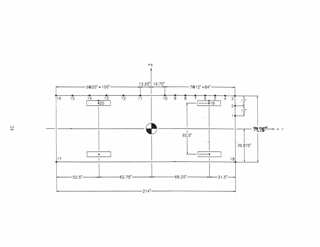
+5
S@20" : 100" 13.25" 16.75"
7@12" : 84"
I 1 1 I 116 15 14 13 12 11 10 9 (1_6
! 19
5 4 3 1 ;" I ; 20 I I 2-t 12"
1 ---1
~ I T~· 65.5"
L-·. 39.875"
I • I I
7s'...!....- + r
17 I I 18
50.5" I 62.75" I 69.25" I 31.5"-
214"

APPENDIX B
TYI'I CAL BARRIER VII INPUT DATA - NWRRS.DAT AND NWRRSM.DAT
25

TRANSITION TO SAFETY S tlAPE - NWRRS . OAT -66 27 25 2 83 15 2 0
12 - GA. NE STED W- BEAM RAILS wi CHANNEL AND BENT PLATE RUBRAILS ( NODE 37/38)
0.0001 0.0001 0.50 300 0 1 5 5 5 5 5 1 1 0 . 0 0 .0 3 75.00 0.0 5 150.00 0 .0 7 225 .00 0 .0 9 300 .00 0.0
11 375 .00 0.0 13 450.00 0.0 15 525.00 0.0 17 600.00 0.0 19 637.50 0.0 21 675.00 0.0 25 712 . 50 0.0 26 712.50 0.0 33 750.00 0.0 34 750.00 0.0 37 76 8.75 0.0 38 768 . 75 0.0 41 787 . 50 0 .0 42 787.50 0.0 45 806.25 0.0 46 806.25 0.0 49 825 .00 0.0 50 825 .00 0.0 53 843. 75 0 .0 54 843.75 0.0 65 900.00 0.0 66 900.00 0.0 1 3 1 1 3 5 1 1 5 7 1 1 7 9 1 1 9 11 1 1
11 13 1 1 13 15 1 1 15 17 1 1 17 19 1 1 19 21 1 1 21 25 3 1 25 33 3 2 33 37 1 2 37 41 1 2 41 45 1 2 45 49 1 2 49 53 1 2 53 65 5 2 26 34 3 2 34 38 1 2 38 42 1 2 42 46 1 2 46 50 1 2 50 54 1 2 546652 1 45 0 . 35
65 63 61 59 45 43 41 39 25 24 23 22 15 14 13 12
5 4 3 2 2 13 0.35
57 37 21 11
1
0.0 0.0 0 .0 0.0 0 .0 0.0 0.0 0 .0 0.0 0. 0 0.0 0.0 0.0 0.0 0.0 0.0 0.0 0 .0 0.0 0 .0 0 .0 0.0 0.0 0.0 0.0
55 35 20 10
53 33 19
9
51 31 18
8
49 29 17
7
66 64 62 60 58 56 54 52 46 44 42
50
100 6 1 2 . 30 2 2.30 3 2 . 30 4 4.60 5 1.42 6 0.693
300 7 1 21. 65
200.0 200.0 2 21. 65
3 6.P
21.65 15.0
8.0 15.0
1. 99 1. 99 1. 99 3.98 1. 58 2.40
0 .0
0.0
0.0
4 21 . 65 9.06 8.0 20.0
5 21.65 9 .06 10.0 30.0
6 21 . 65 9.06 200 .0 200.0
7 21. 65 9.06 200.0 200 . 0
37.50 18.75 9.375 9 . 375 9 . 375 9 . 375
1000.0 2. 0
4.00
30000.0 30000.0 30000.0 30000.0 30000.0 30000.0
1000.0 2 .0
16.0 16.0 5.00
5.00
5.00
4.00 16.0 16 . 0
4.00 16.0
8.00 16. 0
0.50 2 .0
1000.0 2 .0
16.0 8.00
16.0 1000.0
2 .0 1000. 0
2 .0
1.0
47 27 16
6
48
1
6.92 6.92 6.92
13.84 5.4 8.2
250 .0
54.0
54.0
58.5
97.5
250.0
25 0.0
99.5 99.5 99.5
199.0 5.0 5.0
10000.0
92 . 88
92.88
92.88
116.10
5.0
10000.0
20
68.5 0 . 10 68 .5 0 . 10 68.5 0 . 10
137 .00.10 23.15 0.10 17.71 0.10
10000.0 0 . 10
12 - Ga uge W- Beam Rai 1 12 -Gauge W- Beam Rail 12 -Gauge W-Beam Rail Nested 12- Gauge W- Beam Rail Bent plate Rubrail (Fy:56.9k) C6x8.2 chann el Rail ( Fy:86 .4k )
strong pos t Anchor
270.62 0.10 w6x9x6' Post (43. 3" embedment depth)
336.420.10 W6x9x6.5 ' PoSt ( 49 .4" embedment depth)
336 .42 0.10 w6x9x6. 5' Post ( 49 .4" embedment depth)
553 . 59 0.10 w8x13x7. 5 ' post (61. 5" embedment depth
10000 . 0 0.10
10000.0 0.10
Rlgid Post In Y- Oirection only
St rong Post Anchor

1 1 2 16 1 101 0.0 0 .0 0.0 17 17 18 20 1 102 0.0 0.0 0.0 21 21 22 24 1 103 0.0 0.0 0.0 25 25 27 28 2 103 0 . 0 0.0 0.0 29 33 35 44 2 104 0.0 0.0 0 .0 45 26 28 56 2 105 0.0 0.0 0.0 57 50 52 64 2 106 0.0 0 .0 0.0 65 1 66 2 301 0.0 0.0 0.0 0.0 0.0 67 5 72 2 302 0.0 0.0 0.0 0.0 0.0 73 17 75 2 303 0.0 0.0 0.0 0.0 0 .0 76 25 26 77 8 304 0 .0 0.0 0.0 0.0 0.0 78 37 38 79 4 304 0.0 0.0 0 .0 0.0 0 .0 80 45 46 81 4 305 0.0 0.0 0.0 0.0 0.0 82 53 54 306 0.0 0 .0 0 .0 0 .0 0.0 83 65 66 307 0.0 0.0 0.0 0.0 0.0
4400.0 40000.0 20 6 4 0 1 1 0 .055 0 . 12 6 .00 17.0 2 0.057 0.15 7 .00 18 .0 3 0.062 0.18 10.00 12 .0 4 0.110 0.35 12.00 6 .0 5 0.35 0.45 6.00 5.0 6 1.45 1. 50 15.00 1.0 1 100.75 15.875 1 12.0 1 0 0 0 2 100.75 27.875 1 12.0 1 0 0 0 3 100.75 39 . 875 2 12.0 1 0 0 0 4 88.75 39 . 875 2 12.0 1 0 0 0 5 76.75 39.875 2 12 .0 1 0 0 0 6 64.75 39.875 2 12 .0 1 0 0 0 7 52.75 39 . 875 2 12.0 1 0 0 0 8 40.75 39.875 2 12 .0 1 0 0 a 9 28.75 39 . 875 2 12 .0 1 0 0 0
10 16.75 39 . 875 2 12 .0 1 0 0 0 11 -13 .25 39.875 3 12.0 1 0 0 0 12 -33 .25 39 . 875 3 12.0 1 0 0 0 13 -53 .25 39 . 875 3 12 .0 1 0 0 0 14 - 73 . 25 39 . 875 3 12 .0 1 0 0 0 15 - 93.25 39 . 875 3 12 .0 1 0 0 0 16 -113.25 39.875 4 12 . 0 1 0 0 0 17 -113.25 - 39.875 4 12.0 a 0 0 0 18 100 . 75 - 39.875 1 12.0 0 0 0 0 19 69.25 37.75 5 1.0 1 1 0 0 20 - 62.75 37.75 6 1.0 1 1 0 0 1 69.25 32.75 0.0 608 . 2 69.25 -32.75 0.0 608. 3 - 62.75 32.75 0.0 492. 4 - 62 . 75 - 32 . 75 0.0 492. 1 0.0 0.0 3 768.75 0.0 25 .0 62.14 0.0 0.0 1.0
27

TRANSITION TO SAFETY SHAPE - N\\IRRSM . DAT - 12-GA. NESTED lv- BEAM RAILS W/ CHANNEL AND BENT PLATE RUBRAILS (NODE 37 / 38) 66 27 25 2 83 15 2 0
0.0001 0 .0001 0 . 50 300 0 1 5 5 5 5 5 1 1 0 . 0 0 . 0 3 75.00 0 . 0 5 150.00 0 . 0 7 225.00 0.0 9 300.00 0.0
11 375.00 0.0 13 450.00 0.0 15 525.00 0.0 17 600.00 0.0 19 637 . 50 0.0 21 675 .00 0.0 25 712 . 50 0.0 26 712.50 0.0 33 750.00 0.0 34 750 .00 0.0 37 768.75 0.0 38 768.75 0.0 41 787 . 50 0.0 42 787.50 0.0 45 806 . 25 0 .0 46 806 . 25 0 .0 49 825 .00 0 . 0 50 825 .00 0 . 0 53 843 . 75 0 . 0 54 843 . 75 0 . 0 65 900.00 0.0 66 900 .00 0.0 1 3 1 1 3 5 1 1 5 711 7 9 1 1 9 11 1 1
11 13 1 1 13 15 1 1 15 17 1 1 17 19 1 1 19 21 1 1 21 25 3 1 25 33 3 2 33 37 1 2 37 41 1 2 41 45 1 2 45 49 1 2 49 53 1 2 53 65 5 2 26 34 3 2 34 38 1 2 38 42 1 2 42 46 1 2 46 50 1 2 50 54 1 2 54 66 5 2 1 45 0.35
65 63 61 59 45 43 41 39 25 24 23 22 15 14 13 12
5 4 3 2 2 13 0.35
57 37 21 11
1
0.0 0.0 0.0 0.0 0.0 0 . 0 0 . 0 0.0 0.0 0 . 0 0.0 0.0 0 . 0 0.0 0.0 0.0 0.0 0.0 0.0 0.0 0.0 0.0 0.0 0.0 0 . 0
55 35 20 10
53 33 19
9
51 31 18
8
49 29 17
7
66 64 62 60 58 56 54 52 46 44 42
50
100 6 1 2.30 2 2.30 3 2.30 4 4.60 5 1.42 6 0.693
300 7 1 21. 65
1. 99 1. 99 1. 99 3 . 98 1. 58 2 . 40
0.0 200.0 200.0
2 21. 65
3
4
5
6.p 21. 65
8.0 21.65
8.0 21.65
10 .0 6 21. 65
0.0 15.0
0.0 15 .0
9 . 06 20.0
9 .06 30 .0
9.06 200.0 200.0
7 21.65 9.06 200.0 200.0
37.50 18.75 9.375 9.375 9 . 375 9.375
1000.0 2 .0
4.00 16.0
4.00 16.0
4.00 16.0
8.00 16.0
0 . 50 2 .0
1000.0 2 .0
30000.0 30000.0 30000 .0 30000.0 30000 .0 30000.0
1000.0 2 . 0
5 .00 16.0
5.00 16.0
5.00 16.0
8.00 16.0
21. 88 6.0
1000.0 2 .0
1.0
47 27 16
6
48
1
6.92 6.92 6.92
13.84 5.4 8.2
250.0
54.0
54.0
58.5
97.5
189. 7
250.0
99.5 99.5 99.5
199.0 5.0 5.0
10000 a 92. M8
92.88
92 . 88
116.10
5.0
10000.0
28
68.5 0.10 12 - Gauge W- Beam Rail 68 . 5 0.10 12 - Gauge W-Beam Rail 68 . 5 0.10 12- Gauge \\I - Beam Rail
137 . 00.10 Nested 12 -Gauge W-Beam Rail 23.15 0.10 Bent plate Ru rail ( Fy=56.9k) 17.71 0.10 C6x8.2 channel Rail ( Fy=86 .4k)
10000 . 0 0.10 Strong post Anchor
270.62 0 . 10 w6x9x6' POS1: 43 . 3" embedment dep1:h
336.42 0 . 10 "6x9x6.5' POS1: 49.4" embedment depth
336 . 42 0.10 w6x9x6.5' Post 49.4" embedment depth
553.590.10 W8x13x7 . 5 ' pos t 61. 5" embedmen1: depth
236 . 85 0.10 Crushabl e pipe Post v- Direction only
10000.0 0.10 Strong Post Anchor

1 1 2 16 1 101 0.0 0.0 0.0 17 17 18 20 1 102 0.0 0.0 0.0 21 21 22 24 1 103 0.0 0.0 0.0 25 25 27 28 2 103 0.0 0.0 0.0 29 33 35 44 2 104 0.0 0.0 0.0 45 26 28 56 2 105 0.0 0.0 0.0 57 50 52 64 2 106 0.0 0.0 0.0 65 1 66 2 301 0.0 0.0 0.0 0.0 0.0 67 5 72 2 302 0.0 0.0 0.0 0.0 0.0 73 17 75 2 303 0.0 0.0 0.0 0.0 0.0 76 25 26 77 8 304 0 . 0 0.0 0 .0 0.0 0.0 78 37 38 79 4 304 0.0 0.0 0.0 0.0 0.0 80 45 46 81 4 305 0.0 0.0 0 .0 0 .0 0.0 82 53 54 306 0 .0 0.0 0.0 0.0 0.0 83 65 66 307 0 . 0 0 .0 0 .0 0 .0 0 .0
4400.0 40000.0 20 6 4 0 1 1 0.055 0 . 12 6.00 17 .0 2 0.057 0.15 7.00 18.0 3 0.062 0.18 10.00 12.0 4 0.110 0. 35 12 . 00 6.0 5 0.35 0 .45 6.00 5.0 6 1. 45 1. 50 15 .00 1.0 1 100 . 75 15.875 1 12 .0 1 0 0 0 2 100.75 27.875 1 12.0 1 0 0 0 3 100 . 75 39 . 875 2 12.0 1 0 0 0 4 88 .7 5 39 . 875 2 12.0 1 0 0 0 5 76.75 39 . 875 2 12.0 1 0 0 0 6 64.75 39 . 875 2 12 .0 1 0 0 0 7 52.75 39 . 875 2 12 .0 1 0 0 0 8 40.75 39 . 875 2 12.0 1 0 0 0 9 28.75 39.875 2 12.0 1 0 a 0
10 16.75 39.875 2 12.0 1 0 0 0 11 - 13.25 39.875 3 12.0 1 0 a 0 12 - 33.25 39.875 3 12 . 0 1 0 0 0 13 -53 . 25 39 . 875 3 12 .0 1 0 0 0 14 -73 . 25 39.875 3 12 .0 1 a 0 0 15 - 93 . 25 39.875 3 12.0 1 0 0 0 16 -113.25 39.875 4 12.0 1 0 0 0 17 - 113.25 -39.875 4 12.0 0 0 0 0 18 100.75 - 39 . 875 1 12 . 0 0 0 0 0 19 69.25 37.75 5 1.0 1 1 0 0 20 - 62.75 37.75 6 1.0 1 1 0 0
1 69.25 32 . 75 0.0 608. 2 69.25 - 32 .75 0.0 608. 3 - 62 .75 32. 75 0 .0 492. 4 - 62.75 - 32. 75 0.0 492. 1 0.0 0.0 3 768 . 75 0.0 25.0 62.14 0.0 0 .0 1.0
29

APPENDIX C
COMPUTER SIMULA TION RESULTS - NESTED W-BEAM TRANS ITION
30

w
Table C- l. Computer Simulation Test Matrix and Results for Nested W-Beam Transition without Crushable Spacer Tube
W-Beam Deflection When Vehicle Test No. Impact Impact Maximum Maximum Maximum Node 3 Near W-Beam Node 53 Transition Remarks
Node Distance! W-Beam W-Beam W-Beam POSts ( in.) Dynamic Permanent Set Tension Removed
Deflection Deflection (kips) 8 (in.) 8 ( in.) Net Durin!!. (in.) ( in.) Node 51 Node 53 8 (in.)' Simulation
NWRR I ~9 30 112.50 7.25 3.89 83.86 NA NA NA No T,"=5" rubrai!. Rigid support post used.
NWRR2 31 '32 103.125 6.20 3.13 75.09 NA NA NA No Ty=5k rubrail. Rigid suppan post used.
N\\·RR3 33 34 93.75 5.53 2.61 67.29 1.40 0.01 1.39 No Ty=5k rubrai!. Rigid SUppOI1 POSt used.
NWRR4 35 '36 84.375 4.76 2.50 61.94 1.75 0.05 1.70 No Ty=5k rubrail. Rigid support post used.
NWRR53 37/38 75.00 4.24 2.18 54.59 1.81 0.06 1.75 No Ty=.5' rubrail. Rigid support post • used.
NWRR6 3940 65.625 3.41 1.60 38.66 1.76 0.06 1.70 No Ty=5k rubrail. Rigid support post used.
NWRR7 .j I '42 56.25 2.68 1.44 29.08 1.55 0.07 1.48 No Ty=5~ rubrai!. Rigid support post used.
Longitudinal distance measured from impact location to centerl ine of steel space rube. Relath'e net difference in W-beam displacement between rail nodes 51 and 53 is used to help predict pocketing or snagging when vehicle node 3 reaches rail node 53. Assumed critical impact point (eIP).

Table C-2. Computer Simulation Test Matrix and Results for Nested W-Beam Transition with Crushable Spacer Tube
W-Beam Deflection When Test No. Impact Impact Maximum Maximum Maximum Vehicle Node 3 Near W-Beam Transition Remarks
Node Distance 1 W-Beam W-Beam W-Beam Node 53 Posts (in. ) Dvnamic Permanent Set Tension Removed
Deflection Deflection (kips) During (in .) ( in .) 8 (in .) @ 8 (in) @ Net SimulatIon
Node 5 I Node 53 8 (in.):
NWRRMI 29:30 112.50 7.27 4.02 80.99 NA NA NA No Ty=5' rubrail. Crushable support post used.
NWRRM2 31 '32 103.125 6.23 3.34 70.72 NA NA NA No Ty=5' rubrail. Crushable support post used.
NWRRM3 33 '34 93 .75 5.62 2.93 57.84 NA NA NA No Ty=5' rubrail. Crushable support post used.
NWRRM4 35 '36 84.375 5.28 3.20 48.75 4.42 3.47 0.95 No Ty=5' rubra il. Crushable support post used.
NWRRM5' 37138 75.00. 5.23 3.69 50.96 5.20 4.48 0.72 No Ty=5"rubraiL Crusbable support post used.
NWRRM6 39140 65 .625 5.69 4.77 74.75 5.43 4.96 0.47 No T y=5' rubrail. Crushable support post used.
NWRRM7' 4 1142 56.25 7. I 7 4.1 I 117.39 5.34 5.30 0.04 Yes Ty=5' rubrail. Crushable support post used.
Longitudinal distance measured from impact location to centerline of steel space rube. Relative net difference in W-beam displacement between rail nodes 51 and 53 is used to help predict pocketing or snagging when vehicle node 3 reaches ra il node 53. Assumed crit ical impact point (CIP). During simulation no. NWRRM7. the support post was removed from the model. This occurred after the dynamic rail deflection at node 53 exceeded the post deflection limit of 6 in. which was based on the available crush distance of the steel spacer tube. However. the model was not revised since the post deflection limit was not exceeded in the previous simulation runs.

APPENDIX D
BARRIER vn COMPUTER MODEL - BARRIER
33

0" 15H J5D" =" 'co" 315" 4SO" 5ZS l 1
6){15
w_ I Ie ....., I- OIILo~ I Z5"'I_ OIIL.0""5
w , • , ~ , , , • ..,.
Z 3 · i- 5 , 7 8 1 I. II /2 13 14 15
(1) <Zl <1l @ ~ @ CiJ ® GJ @ ® @ ® ® @
" '" :
" .",' '" ~ '" ~"<IS &XIS
u.
~
~ 3 + ~ "
f5] g@ ~
3 4 s
~ev;seJ ~kl~7 i Rev'Sed II/roll
!="Hwl1 f'rtject - R v iseJ 4/.s/rQ RI= V~rS;D" BiI< R""l5e< -<1 17m gF
s 0
In_ " N ffi ~8 I(l r0..5-t'L,co...tifl i;" .) i' " .. C\)
""zs" \ I
(,(; '" t.."''-'"-''''''''''' u. . i.. . ~rn 177789 J...R.. lyre.
I5fjJ ~ ~~ M1 §ij@ "" ... _ be 5
~ 7 &4~ fos+ .. -rYf<-

APPENDrX E
TYPICAL BARRIER VII INPUT DATA - NEBT2RVNIB2N.DAT
35

NEBRASKA 'S TRANSITION TO CONCRETE BUnRESS WITH BACKUP RAIL & NESTED THRIE - Run 1B2N @ Node 27 - version B Extra postlz 44 20 16 2 58 22 2 0 0.00001 0 . 00001 0.60 6000 0 10 50 50 50 50 50 10
1 0.0 0.0 3 75 . 00 0.0 5 150.00 0.0 7 225.00 0.0 9 300.00 0.0
11 375 . 00 0.0 13 450.00 0 . 0 15 525.00 0.0 17 600.00 0.0 19 637 . 50 0.0 21 675.00 0 . 0 25 712 . 50 0.0 29 750 . 00 0.0 30 750.00 0.0 37 787.50 0.0 38 787 . 50 0.0 41 806.25 0.0 42 800.00 0.0 43 815 . 625 0.0 44 825.00 0 . 0
1 3 1 1 3 5 1 1 5 711 7 9 1 1 9 11 1 1
11 13 1 1 13 15 1 1 15 17 1 1 17 19 1 1 19 21 1 1 21 25 3 1 25 29 3 1 29 37 3 2 37 41 1 2 30 38 3 2 38 42 1 2
1 37 0.35 44 43 41 39 27 26 25 24 17 16 15 14
7 6 5 4 2 7 0.35
37 23 13
3
0.0 0.0 0.0 0.0 0.0 0.0 0.0 0 . 0 0.0 0 .0 0.0 0.0 0.0 0.0 0.0 0.0
35 22 12
2
33 21 11
1
42 40 38 36 34 32 30 100 8
1 2 3 4 5 6 7 8
300 10
2 . 30 2 . 475
2 . 84 3.205 3 . 575
7.52 9.58 9.58
1 21.65 200.0 200 0
2 21. 65
3
4
5
6
6.0 21. 65
15.0 21. 65
15.0 21. 65
15.0 21. 65
15.0
30.0
30.0
30.0
20.0 55.0
1. 99 2 . 125
2.40 2 . 68 2.96 6.20 4.79 4.79
0.0
0.0
0.0
0.0
0.0
0.0
37 . 50 18.75 18 . 75 18 . 75 18.75 9.375 9.375 6.25
1000.0 2.0
1.15 16 0
8 . 00 16.0
8.00 16.0
8.00 16.0
8.00 16.0
7 21.65 ' 21.00 8.00 20.0 55.0
8 21. 65 35.0
9 21. 00 35.0
400.0 400.0 10 21. 65
400.0 400.0 1 1 2 16
17 17 18 18 18 19 19 19 20 20 20 21 21 21 22 29 29 11 33 37 39 35 41 43 36 43 44
28 32 34
0.0
0.0
o 0
16.0 196.0
10.0 2000.0
1.0 2000.0
1.0 1 101 1. 102 1 103 1. 104 1 .lOS 1 106 2 106 2 106
106 106
11 20 10
29 19
9
30000.0 30000 . 0 30000.0 30000.0 30000.0 30000 . 0 30000 . 0 30000.0
1000.0 2.0
2 . 46 16.0
8.00 16.0
8.00 16.0
8.00 16.0
8.00 16.0
8.00 16.0
196.0 10.0
2000.0 1.0
2000.0 1.0 0 .0 0.0 0.0 0.0 0.0 0.0 0.0 0.0 0.0 0.0
1.0 1
28 18
8
6.92 7.405 8 . 375
9.35 10.325
21. 62 1. 83 1. 83
0.0 0.0 0.0 0.0 0 .0 0.0 0.0 0.0 0.0 0.0
250.0
54.0
97.5
105 . 0
105.0
212.5
212.5
100 . 0
500.0
500.0
99.5 106 . 25
120.0 134 .0 148 0 310.0
1.0 1.0
1000.0
96.6
256.5
256.5
256 . 5
462.24
462.24
·20.0
2500.0
2500.0
0.0 0.0 0.0 0.0 0.0 0.0 0.0 0.0 0.0 0.0
36
68 . 5 0.10 73.75 0.10
84 .0 0 . 10 94 . 0 0.10
104.25 0 . 10 219.0 0.10 1.560.10 TS 1.560.10 TS
4x4x5/16 Backup Rai 1 (zero Strength) 4x4x5/16 Back up Rai 1 (zero strength)
1000.0 0.10 Simulated upstream Anchor
255.57 0 . 10 w6x9 steel Post
495 . 780 .10 w6x15 steel Post
580.87 0.10 w6x15 steel Post
539.52 0.10 w6x15 steel post
984.21 0.10 w6x25 steel Post
984.21 0.10 w6x25 Steel post
626 . 770.10 Simu l ated Midspan Post
2500.0 0.10 simu l ated Downstream Anchor
2500.0 0.10 Simulated Downstream Anchor

37 30 32 40 2 107 0.0 0.0 0.0 41 38 40 42 2 108 0.0 0 . 0 0.0 43 1 44 2 301 0.0 0.0 0 .0 0.0 0.0 45 5 49 2 302 0.0 0.0 0 .0 0.0 0.0 50 15 51 2 303 0.0 0.0 0.0 0.0 0.0 52 19 304 0.0 0.0 0.0 0.0 0.0 53 21 305 0.0 0.0 0.0 0.0 0 .0 54 25 306 0.0 0.0 0.0 0 .0 0.0 55 29 30 307 0.0 0 .0 0.0 0.0 0 .0 56 37 308 0.0 0.0 0.0 0.0 0 .0 57 42 309 0.0 0.0 0.0 0 . 0 0 . 0 58 44 310 0.0 0.0 0.0 0.0 0.0 4400.0 40000.0 20 6 4 0 1 1 0 .055 0.12 6 . 00 17.0 2 0.057 0.15 7.00 18.0 3 0.062 0.18 10 . 00 12.0 4 0.110 0.35 12.00 6 .0 5 0.35 0.45 6.00 5.0 6 1. 45 1. 50 15.00 1.0 1 100.75 15 . 875 1 12.0 1 0 0 0 2 100.75 27.875 1 12.0 1 0 0 0 3 100.75 39.875 2 12.0 1 0 0 0 4 88.75 39.875 2 12.0 1 0 0 0 5 76.75 39.875 2 12.0 1 0 0 0 6 64.75 39.875 2 12.0 1 0 0 0 7 52.75 39.875 2 12.0 1 0 0 0 8 40 . 75 39.875 2 12 . 0 1 0 0 0 9 28.75 39.875 2 12.0 1 0 0 0
10 16.75 39 . 875 2 12 . 0 1 0 0 0 11 - 13.25 39 . 875 3 12.0 1 0 0 0 12 - JJ.25 39.875 3 12.0 1 0 0 0 13 -53.25 39.875 3 12.0 1 0 0 0 14 -73.25 39.875 3 12 .0 1 0 0 0 15 - 93.25 39.875 3 12.0 1 0 0 0 16 - 113.25 39 .875 4 12.0 1 0 0 0 17 - 113.25 - 39 .875 4 12.0 0 0 0 0 18 100 . 75 - 39.875 1 12.0 0 0 0 0 19 69 . 25 37 . 75 5 1.0 1 0 0 0 20 -62 . 75 37.75 6 1.0 1 0 0 0 1 69.25 32.75 0.0 608. 2 69.25 - 32.75 0.0 608. 3 -62 .75 32.75 0.0 492. 4 - 62.75 - 32.75 0.0 492. 1 0.0 0.0 3 731.250 0.0 25 .0 62.14 0 .0 0.0 1.0
37

APPENDIX If
COMPUTER SIMULATION RESULTS - NESTE)) THRIE BEAM TRANSITION
38

Table F-l. Computer Simulation Test Matrix and Results for Nested Thrie Beam Transition with Backup Tube Rail
Wheel Snag Potential On Concrete End Section2
Test No. Impact Impact Maximum Maximum Maximum Node Distance1 Thrie Beam Thrie Beam Thrie Beam
(in.) Dvnamic Permanent Set Tension Deflection Deflection (kips) Ii (in.) Ii (in. ) Snag
(in.) (in .) Steel Rim Rubber Tire (YfN) Lateral Distance Lateral Distance
NEBT2RUN6B2 25 87.50 6.23 5.31 99.42 4.25 5.05 N
NEBTIRUN5 B2 26 78.125 6.73 5.57 122.97 5.48 605 N
NEBTIRUNiB2 27 68.7.5 6.71 5.54 138.16 6.06 6.26 N
NEBTIRUN2B2 28 59.375 6.19 5.52 135.42 5.97 5.73 N
NEBTIRUN3B2 2Ji 50.00 6.07 5.42 130.13 5.43 4.25 N
NEBTIRUN4B2 31 40 .625 5.41 5.10 120.06 3.84 2.05 N
J _ Longitudinal distance measured from impact location to upstream end of tapered concrete end section. : - The upstream end of the tapered concrete end section is positioned approximately 8 in. away from the front face of the concrete buttress.


