
Belonging to
Important: Assembly / maintenance of the appliance must be carried out by qualified personnel and inaccordance with applicable laws and regulations.The manufacturer assumes no responsibility for the use of products that have to comply with particularenvironmental and / or installation standards.
Important noteBefore connecting the equipment, it is recommended that you read the instruction manual carefully and keepit for future reference. It is also recommended to perform the electrical connections correctly as per encloseddrawings, observing the instructions and the Standards.N.B. Refer to the documentation in all cases where the symbol is on the side
Channel: Beinat gas solutionsElectric connections also available on
CONFORMITY
Installationand user guide
EN 50194
EN 45544-1-3EN 50270
EN 61010-1Compliant EN 60079-29-1
Installation EN 60079-29-2Reports issued by TUV Italia
INSTALL IN SAFEAREA, NO ATEX
Control Unit from 1 to 3 Conventional sensors GS300M Rev. 7
Through the connection of 3 remote probe, the GS300M control unit has been designed and built according toEuropean regulations to detect the presence of toxic and/or explosive gas.A microprocessor is used to create a complete surveillance and control system with maximum flexibility.Thanks to this and its other features, it is suitable for: civil use, industrial use and small underground car parks.
The GS300M control unit has three danger levels:1st LEVEL, 1st Alarm. This was set to 8 % of L.E.L. (120ppm) for all probes.2nd LEVEL, 2nd Alarm. This was set at 13% of L.E.L. (200ppm) for all probes.3rd LEVEL, Main Alarm. This was set at 20 % of L.E.L. (300ppm) for all probes.Other technical features make this control unit extremely versatile and reliable; for example, by using a series ofmicro-switches it is possible to:Select or disable the probe when not installed or faulty;Select the type of gas to be detected (toxic or explosive);Choose the relay functioning mode (pulsed or continuous);Choose the main alarm relay shut-down time.
A TEST button to check the efficiency of the unit and connected probes ensures total control of the GS300M.
The IP44 external structure was designed for installations on walls, or on electrical panels by means of specialbrackets. In addition to the alarm signal light, it is fitted with an internal buzzer.

Page 2
Precautions
CHECK the integrity of the unit after having removed it from the box.Check that the data written on the box correspond to the type of gas used.When doing the electrical connections, follow the drawing closely.Any use of the detector for purposes other than the intended one is considered improper, andas a result of which BEINAT S.r.l. therefore disclaims any responsibility for possible damagescaused to people, animals or objects.
IMPORTANT: Do not test the device using the gas tap as this does not necessarily providesufficient concentration to activate the main alarm.
TERMS and EXPECTATIONS: The installation of the GS300M control unit, its ordinary and extraordinary maintenance,every six months, and its out of service removal at the end of the functional life guaranteed by the manufacturer, mustbe carried out by authorized or specialized personnel.In order to achieve long and satisfactory use of your GS300M digital control unit, use it by respecting the followingprecautions.
Do not allow it to become wet.The control unit can be seriously damaged as it is not waterproof either when immersed in water or exposed to highlevels of humidity.Do not drop it.Heavy knocks or falls during transportation or installation can damage the appliance.Avoid abrupt temperature fluctuations.Sudden temperature variations can cause condensation and the control unit could work poorly.Over a temperature of about +45°C, the monitor turns black. In such case it should cool down to become visible again.CleaningNever clean the device with chemical products. If necessary, wash with a moist cloth.
Technical Specifications
Main Power Supply boxed version ................................................................ 110/230VAC 50/60Hz ±10%Secondary Power Through Battery Max 2,2 Ah (Optional) ..................................................... 12 V ±10%Battery Charger max 2.2 Ah .................................................................................................... ControlledPower Demand ...........................................................................................................11 W max @ 230VPower Demand ................................................................................................................6 W max @ 12VRelay Contact Range ................................................................... 10A 250VAC resistive - 5A 30Vdc resistive
1st Pre Alarm ......................................................................................... Set to 8% of L.E.L. or 120ppm CO2nd Pre Alarm ....................................................................................... Set to 13% of L.E.L. or 200ppm COFinal Alarm ......................................................................................... Set to 20% of L.E.L. or 300ppm CO
Number of Conventional Sensors that can be connected ....................................................................... 3Micro-switches to include or exclude the probes ................................................................ 1 per each probeConnectable probes ............................. Semi-conductor, Catalytic, Electrochemical cell, Pellistore, Infrared RaysType of faults detected by Fault Circuit ................................................... Interruption, short circuit, or wearInput Signal ......................................................................................................... 4 ÷ 20 mA on 220 ohmDevice Accuracy ........................................................................................................................ 1% FSResponse Time ............................................................................................................................ < 2”Control Unit .................................................................................................................... microprocessor
Functioning Temperature ................................................................................................... -10°C ÷ +60°CWaiting, blinking period ........................................................................................................... 90 secondsManual Test ............................................................................................................................ Built inMax. distance between probes and unit .......................................................................................... 100 mCable diameter for connecting probes ............................................................................................. 1 mm2
Connection: The cable of connection of the probe must not be installed together with the power cables.Otherwise, make sure to use a shielded cableSize DIN EN 50092 ........................................................................................................... 144*144*110Degree of Protection ..................................................................................................................... IP44Warranty.......................................................................................................................................3 years

Page 3
Main Compatible Probes
WARNING!
SG500 Catalytic IP30 Domestic Use CH4-LPG 0÷100% LEL 4÷20 mA ±5 % NO NO
SG544 Catalytic IP44 Tertiary CH4-LPG 0÷100% LEL 4÷20 mA ±5 % NO NO
SGM595 Catalytic IP55 Tertiary See catalogue 0÷100% LEL 4÷20 mA ±5 % Yes NO
SGM595/A Catalytic IP66 Zone 2 See catalogue 0÷100% LEL 4÷20 mA ±5 % Yes NO
SGM533 Catalytic IP55 Tertiary See catalogue 0÷100% LEL 4÷20 mA ±5 % Yes Yes
SG800 Catalytic IP66 Zone 2 See catalogue 0÷100% LEL 4÷20 mA ±5 % Yes Yes
HCF100 SemiCondut IP55 Tertiary FREON 0÷300% ppm 4÷20 mA ±5 % NO Yes
SG895 Pellistor ATEX Zone 1 See catalogue 0÷100% LEL 4÷20 mA ±5 % Yes NO
SG580 Catalytic IP66 Zone 2 See catalogue 0÷100% LEL 4÷20 mA ±5 % Yes NO
SGF100 Catalytic IP64 Zone 2 Methane 0÷100% LEL 4÷20 mA ±5 % Yes Yes
SGF102 Catalytic IP64 Zone 2 LPG 0÷100% LEL 4÷20 mA ±5 % Yes Yes
SGF104 Optical Fluores IP64 Zone 2 Oxygen In % 4÷20 mA ±5 % Yes Yes
SGF106 SemiCondut IP64 Zone 2 FREON 0÷300% ppm 4÷20 mA ±5 % Yes Yes
SGF108 Elettrochimica IP64 Zone 2 H2S 0÷300% ppm 4÷20 mA ±5 % Yes Yes
SGF110 Electrochemical IP64 Zone 2 C O 0÷300% ppm 4÷20 mA ±5 % Yes Yes
SGF112 Catalytic IP64 Zone 2 Hydrogen 0÷100% LEL 4÷20 mA ±5 % Yes Yes
CO100r Electrochemical IP55 Tertiary C O 0÷300% ppm 4÷20 mA ±5 % Yes Yes
CO100Ar Electrochemical IP66 Zone 2 C O 0÷300% ppm 4÷20 mA ±5 % Yes Yes
SG800duct Catalytic IP66 Zone 2 CH4LPG 0÷100% LEL 4÷20 mA ±5 % Yes Yes
CO200duct Electrochemical IP66 Zone 2 C O 0÷300% ppm 4÷20 mA ±5 % Yes Yes
Application in:
Domestic: family accommodation. Local boilers up to 70 kW-hTertiary Areas: Large Rooms Boilers, Workshops, Material Deposits, Industrial Kitchens, Large Buildings, Buildings.Zone 2 - Mixed IP66 ATEX: High probability of escape, high risk locations, premises for which applicable regulations apply.Zone 1 - Hazardous Area, High Risk Hazards, Rooms for Which Regulations, Tanks, Control Valves are in force.
Probe Sensor Degree Suitable for Gas Range Output Precis. Calibration RelayProtec. Detected Working Automatic
Sensor
WARNING! Actions to be taken in case of alarmGas1) Put out all free flames.2) Close the main gas tap or the LPG cylinder tap.3) Do not turn any lights on or off; do not turn on any electrical device or appliance.4) Open windows and doors in order to increase ventilation.If the alarm stops, its cause must be found and the relevant consequent measures taken.If the alarm continues and the cause of gas presence cannot be found or removed, abandon the building and callthe emergency services when outside (fire department, distributors, etc.)IMPORTANT: The operation test should not be carried out with the gas tap as this does not guarantee a sufficientconcentration to activate the general alarm.Warning !!If you have the following symptoms: vomiting, sleepiness, or else, go to the closest first aid stationand inform the operators that you could have been poisoned by Carbon Monoxide, or by an excessor deficiency of oxygen
MAINTENANCEThe user periodically (every 6 months) must perform a check of the operation of thecontrol unit by spraying a suitable test gas at the base of the probes connected until thealarm condition is reached.• At least once a year make a more accurate check by a specialist technician. • Disabling the detector must be carried out by qualified personnel.

Page 4
Dimensions
RESET
TEST
14
4
1 4 4
14
0
1 4 0
14
01 0 8
7 7
Brackets
Screws 5 ma
(Optional)

Page 5
1) MAINS LED. It lights up when electrical power is connected. Initially, this LED blinks for about 1 minutewaiting for the check.When this LED is blinking the GS300M is not capable of detecting gas.
2) BATTERY LED. This LED lights up when no mains is present and the GS300M is powered by the battery.When this LED is blinking the battery is flat.3) OVER LOAD BATTERY LED (battery overload): If this LED turns on, it means the battery is not connectedproperly, or it has an anomalous voltage absorption. Please check the battery and the connection cables.4) OVER LOAD PROBE LED. If this LED turns on, it means there is a short circuit or high voltage absorptionin the probes.
5) 1st PRE ALARM LED. This LED will light up when the gas concentration level has reached the preset 8%of LEL and the 1st THRESHOLD relay contact is closed.6) 2nd PRE ALARM LED. This LED will light up when the gas concentration level has reached the preset 13%of LEL and the 2nd THRESHOLD relay contact is closed.7) MAIN ALARM LED. This LED will light up when the gas concentration level has reached 20% of LEL andthe MAIN ALARM relay contact is closed.
8) Zone Alarm MEMORY LED. If this LED turns on, it means an alarm has occurred.9) EXPLOSIVE GAS LED. This LED will light up when the relevant microswitch is set to EXP.10) FAULT LED. This LED will light up when the probe is faulty, if there is an interruption in the cable connection,or if an error was made during wiring.11) TOXIC GAS LED. This LED will light up when the relevant microswitch is set to TOX.12) scale of gas detection. These LEDs light up in sequence according to the environment gas concentrationlevel increase. When the first LED turns on, the gas concentration level has reached 8% of LEL and the 1st
THRESHOLD relay contact is closed. When the second LED turns on, the gas concentration level has reached13% of LEL and the 2nd THRESHOLD relay contact is closed. When the third LED turns on, the gas concentrationlevel has reached 20% of LEL and the MAIN ALARM relay contact is closed
13) RESET BUTTON. This button is pressed to reset all memories.14) TEST BUTTON. Pressing down the TEST button, you can obtain a gas leakage simulation.This way, all pre-alarm LEDs until the final alarm LED will light up in sequence, switching the correspondentrelays.
Components and commands
Switch 1Selecting positive safetySwitch 2Main alarm relay functioning mode
probes exclusionselecting monitored gas type
S1 S2 S3 1 2 3
Power terminal block Signal terminal block
ON
Battery
Over LoadBattery
Over LoadProbes
2 Alarm
1 Alarm
Test
Reset
Alarm Fault Alarm Fault Alarm Fault
8 13 20120 200 300
8 13 20120 200 300
8 13 20120 200 300
LIEppm
(5)
(6)
(7)
(1)
(2)
(3)
(4) (14)
(13)
(8) (10)(8) (10)(8) (10)
(9)(11) (9)(11) (9)(11)
(12) (12) LIEppm
Main Alarm
GS300M
Page 6
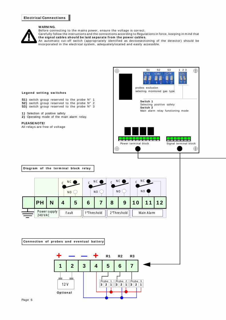
Connection of probes and eventual battery
Legend setting switches
S1) switch group reserved to the probe N° 1S2) switch group reserved to the probe N° 2S3) switch group reserved to the probe N° 3
1) Selection of positive safety2) Operating mode of the main alarm relay.
Diagram of the terminal block relay
Electrical Connections
Power supply240 VAC
PH N 4 5 6 7 8 9 10 11 12
C NC
NO
C NC
NO
C NC
NO
C NC
NO
Fault 1°Threshold 2°Threshold Main Alarm
12 V
1 2 3 4 5 6 7
+ +
Optional
3 2 1Probe 1
3 2 1Probe 2
3 2 1Probe 3
R1 R2 R3
Switch 1Selecting positive safetySwitch 2Main alarm relay functioning mode
probes exclusionselecting monitored gas type
S1 S2 S3 1 2 3
Power terminal block Signal terminal block
WARNING.Before connecting to the mains power, ensure the voltage is correct.Carefully follow the instructions and the connections according to Regulations in force, keeping in mind thatthe signal cables should be laid separate from the power cables.An automatic cut-off switch (appropriately identified as devicesectioning of the detector) should beincorporated in the electrical system, adequatelylocated and easily accessible.
PLEASE NOTE!All relays are free of voltage

Page 7
Connections of a solenoid valve Normally Closed with Positive Safety
Connections of a solenoid valve Normally Closed without Positive Safety
Control unit power supply and connection of a solenoid valve with sirens to 12 VDC troughan alternative source and recharge battery.
Connection examples
NC NA
Ph
N
PH N 4 5 6 7 8 9 10 11 12
Power supply240 VAC
C
NC
NO
C
NC
NO
C
NC
NOC
NC
NO
Fault 1°threshold 2° threshold Alarm Solenoid valves
Ph
N
PH N 4 5 6 7 8 9 10 11 12
Power supply240 VAC
C
NC
NO
C
NC
NO
C
NC
NOC
NC
NO
Fault 1°threshold 2° threshold Alarm Solenoid valve
Power supply 230/12V
Diode1N 5406 3 2 1
Probe 13 2 1Probe 2
3 2 1Probe 3
Solenoid valve GAS and Sirens 12 VDC
1 2 3 4 5 6 7
+ + R1 R2 R3
12 V
It's not possible to connect directly solenoid valvesor sirens 12V.dc. to the GS300M.

Pagina 8
Connections with Positive Safety disabled and an external powersupply for solenoid valve and siren control to 12 VDC
Connection examples
NC NA
Ph
N
PH N 4 5 6 7 8 9 10 11 12
Power supply230 VAC
C
NC
NO
C
NC
NO
C
NC
NOC
NC
NO
Fault 1°Threshold 2° Threshold Alarm Solenoid valves
Power supply 230/12V
Diode1N 5406
3 2 1Probe 1
3 2 1Probe 2
3 2 1Probe 3
1 2 3 4 5 6 7
+ + R1 R2 R3
12 V

Page 9
Disabling or uninstalling the probesYou can connect 3 probes to the GS300M. The control unit is tested with the probes connected.These micro-switches are also used to disable one or all probes in case of failure.
The GS300M if fitted with three micro-switches in order to select the type of gas that the connected probesshould monitor.The LEL reading is obtained by shifting the switch to ON. Explosive gas.The ppm reading is obtained by shifting the switch to OFF. Toxic gas.
Functioning mode of the Main Alarm relay
Switch 1 – Selection of the intrinsic safetyIn the ON position, the intrinsic safety function is enabled.In the OFF position, the intrinsic safety function is disabled.The relay is energized only when the GS300M goes into main alarm state
Switch 2 – Functioning ModeIn the ON (continuous) position, the relay remains closed until the RESET button is pressed.In the OFF (impulse) position, the relay remains closed for 20 seconds, and then disenergizes afterwards
Zone 1 Zone 2 Zone 3
Micro-switch (1) to enable or disable the zone of the probe.Postion ON enabled Positione OFF disabled
Micro-switch (2) to select the type of gas monitored zone.Position ON reading in LEL - Explosive gasPosition OFF reading in ppm - Toxic gas
Zone 1 Zone 2 Zone 3
Micro-switches 1 Positive SafetyMicro-switches 2 Working mode of the relayMain Alarm
Description of Micro-switches

Page 10
PROBE INSTALLATION INFORMATION
30 cm Light Gases
30 cm Heavy Gases
160 cm Volatile Gases
The GS300M control unit belongs to group II and must be installed in a safe area;Outside the ATEX zone, however, not in boiler rooms or engine room.The control unit must be accessible and visible to the user.
The GS300M is designed so that it can be mounted externally or built into electrical panels.The Control Unit complete cabinet is an equipment suitable for wall mounting and is powered by 110/240 VAC withIP44 protection
When installing, it is good to use the normal care that an electronic equipment requires:- Install the equipment away from excessive heat sources.- Avoid liquids coming into contact with the control unit, remembering that its external structure has IP20 degree ofprotection if installed on the Boxed version (cabinet) supplied to the source is IP44.
The sensors must be selected with an IP degree depending on the area to be controlled (Kitchens, BoilerRooms, Laboratory, etc.) by selecting one of the probes from Beinat from IP30 to ATEX. see page 3
Position of the detection probes
You can connect many types of remote probes to this unit. Therefore, they should be positioned at different heightsdepending on the type of gas to be detected.
These heights are:- 30 cm from the lowest point of the floor in order to detect: Heavy gases (L.P.G. etc.)- 30 cm from the highest point of the ceiling in order to detect: light gases (Methane, etc.)- 160 cm from the lowest point of the floor in order to detect: volatile gases (CO, etc.)
It is important to note that the remote probes should be installed according to the following restrictions:
1) The sensors should not be placed near the appliances to be controlled (boilers, burners, industrial kitchens, etc.)but on the opposite side.2) The sensors should not be affected by smoke, vapour, and moving air, as they could distort their measurement.3) The sensors should not be placed near sources of heat, ventilators or fans.It should be noted that the internal GAS sensors of the probe are perishable components with a variable averagelife span from 5 to 6 years (you can request the relative table). Therefore, after this period of time has elapsed itis advisable to replace them.4) The control of operation and maintenance and / or extraordinary must be carried at least once a year. goodto keepWhen turning on leds fault is necessary make the replacement of the probe by a specialized technician.
Installation and positioning of the sensors

Page 11
1) Apply power using the proper switch. This switch should be fitted with protection fuses.2) You will notice that some LEDs will light up in turn for about 20 seconds, so as to test the LEDs.3) The LED ON will continue blinking for about 2 minutes and then remain ON.Now the GS300M is ready for detection.4) By pressing the MANUAL TEST button, you get the simulation of a gas leak and the unit carries out thefollowing:a) The 1st Pre-alarm LED lights up calibrated to 8% LEL or 120 ppm (referred to CO) switching the relayb) The 2nd Pre-alarm LED lights up calibrated to 13% LEL or 200 ppm (referred to CO) switching the relaythe buzzer will issue a low frequency soundc) The Main alarm LED lights up calibrated to 20% LEL or 300 ppm (referred to CO) switching the relay.The Main alarm LED starts flashing; the buzzer will issue a hight frequency soundWhen releasing the MANUAL TEST button, you will see the opposite: Only the Main Alarm and the zone alarmLEDs will remain ON.5) To complete the general test, issue gas from a pre-calibrated aerosol6) To complete the general test, issue gas from a pre-calibrated aerosol within 20% of L.E.L. A test using acommon cigarette lighter could damage the sensor.If you want to simulate a zone fault, you only need to disconnect the return cable of the corresponding probe.When the fault LED turns on a continuous sound will warn you of the failure. At the same time, the relevantrelay will switch to its position.
If the device does not start up.Check that the 230V mains power is correctly connected. If powered by the battery, check that the 12Vdc poweris correctly connected.If the Fault LED lights up.Check that the connecting cables from the GS300M to the probes are intact, that the probes are properlypowered, and that the signal cable is correctly connected.
If the Over Load Probe LED lights up.Check: that the power polarity has not been inverted, that no short-circuit is present, that the probes were notdamaged during installation, that no excessive current absorption is present.If the Over Load Battery LED lights up.Check that the connection cables are not short-circuited, that the polarity has not been inverted, or that thebattery is not damagedIf the Control Unit is repeatedly issuing an alarm.Check that there are no gas leaks.If the alarm signal and the FAULT indicator light turn on together, check the probes.If the Control Unit is issuing an alarm and does not shut off the devices connected to it.Check that the wiring is correct and that the jumper that carries power to the relay has been set properly. Allrelays must be free from electrical power.Check the drawing of the connections.If a 12Vdc solenoid valve, which does not work well, is connected to the GS300M.Direct connection of 12Vdc solenoid valves or sirens to the GS300M is not permitted.An external power unit must always be used.The GS300M gives a max current of 100mA.
If other problems arise, a specialised and/or authorised technician and/or the Distributor ofBEINAT S.r.l. should be contacted directly.
Troubleshooting and solutions before calling a technician
01
321,1
V.
Vol tmeter
WARNING.This measurement shouldbe performed in clean air.
1 2 3 4 5 6 7
+ +
3 2 1Probe 1
3 2 1Probe 2
3 2 1Probe 3
Turning on the GS300M
BE V.7 43 17
Control Unit GS300M Lo styling è della b & b design
Dealer stamp
Purchase date:
Serial number:
Beinat S.r.l. following the purpose of improving its products, it reserves the right to modify the technical, aesthetic and functional characteristicsat any time and without giving any notice.
INSURANCE. This device is insured by the SOCIETÀ REALE MUTUA for the PRODUCT'S GENERAL LIABILITYup to a maximum of 1,500,000.00 EURO against damages caused by the device in case of failures in functioning.
WARRANTY. The warranty term is 3 years from manufacturing date, in agreement with the followingconditions. The components acknowledged as faulty will be replaced free of charge, excluding the replacementof plastic or aluminium cases, bags, packing, batteries and technical reports.The device must arrive free of shipment charges to BEINAT S.r.l.Defects caused by unauthorized personnel tampering, incorrect installation and negligence resulting fromphenomena outside normal functioning shall be excluded from the warranty.BEINAT S.r.l. is not liable for possible damage, direct or indirect, to people, animals, or things; from productfaults and from its enforced suspension of use.
DISPOSAL OF OLD ELECTRICAL & ELECTRONIC EQUIPMENT.This symbol on the product or its packaging to indicates that this product shall not be treated as household waste. Instead, it shall be handed over tothe applicable collection point for the recycling of electrical and electronic equipment, such as for example:- sales points, in case you buy a new and similar product- local collection points (waste collection center, local recycling center, etc...).By ensuring this product is disposed of correctly, you will help prevent potential negative consequence for the environment and human health, which couldotherwise be caused by inappropriate waste handing of this product. The recycling of materials will help to conserve natural resources. For more detailedinformation about recycling of this product, please contact your local city office, your household waste disposal service or the shop where you purchasedthe product.Attention: in some countries of the European Union, the product is not included in the field of application of the National Law that applies the EuropeanDirective 2002/96/EC and therefore these countries have no obligation to carry out a separate collection at the “end of life” of the product.
Made in Italy IP44
Business - [email protected] support - [email protected]
BEINAT S.r.l.Via Fatebenefratelli 122/C 10077, S. Maurizio C/se (TO) - ITALYTel. 011.921.04.84 - Fax 011.921.14.77http:// www.beinat.com


