Technical Specification
Concertor™N, EA, DP, XPC
[email protected] Tel. +31-152-610-900www.lenntech.com Fax. [email protected] Tel. +31-152-610-900www.lenntech.com Fax. +31-152-616-289
Lenntech

Table of Contents
1 System Description.....................................................................................................................31.1 System overview...................................................................................................................3
1.1.1 Concertor™ N.................................................................................................................31.1.2 Concertor™ EA...............................................................................................................41.1.3 Concertor™ DP.............................................................................................................. 51.1.4 Concertor™ XPC............................................................................................................ 7
2 Product Description....................................................................................................................92.1 N-pump................................................................................................................................. 9
2.1.1 Pump design..................................................................................................................92.1.2 Cables.......................................................................................................................... 122.1.3 Monitoring equipment...............................................................................................122.1.4 Options........................................................................................................................ 122.1.5 Accessories..................................................................................................................12
2.2 FPG 413, FPG 414, APP411..............................................................................................122.2.1 Product design............................................................................................................122.2.2 Approvals.....................................................................................................................132.2.3 Parts..............................................................................................................................13
2.3 FOP 402.............................................................................................................................. 132.3.1 Product design............................................................................................................132.3.2 Approvals.....................................................................................................................132.3.3 Parts..............................................................................................................................14
2.4 FOP 315.............................................................................................................................. 142.4.1 Product design............................................................................................................142.4.2 Approvals.....................................................................................................................142.4.3 Parts..............................................................................................................................152.4.4 The data plate............................................................................................................. 15
3 Technical Reference.................................................................................................................163.1 N-pump...............................................................................................................................16
3.1.1 Motor data................................................................................................................... 163.1.2 Application limits........................................................................................................ 163.1.3 Materials.......................................................................................................................163.1.4 Surface treatment....................................................................................................... 17
3.2 FPG 413, FPG 414, APP411..............................................................................................173.2.1 Dimensions..................................................................................................................173.2.2 Environmental requirements.....................................................................................173.2.3 IP-rating........................................................................................................................173.2.4 Electrical data..............................................................................................................183.2.5 Terminals FPG 413..................................................................................................... 183.2.6 Terminals FPG 414..................................................................................................... 203.2.7 Terminals APP 411......................................................................................................22
3.3 FOP 402.............................................................................................................................. 243.3.1 Dimensions..................................................................................................................243.3.2 Environmental requirements.....................................................................................243.3.3 IP-rating........................................................................................................................243.3.4 Electrical data..............................................................................................................243.3.5 Display data.................................................................................................................243.3.6 Terminals..................................................................................................................... 25
3.4 FOP 315.............................................................................................................................. 253.4.1 Dimensions..................................................................................................................25
Table of Contents
Concertor™ Technical Specification 1

3.4.2 Environmental requirements.....................................................................................253.4.3 IP-rating........................................................................................................................253.4.4 Electrical data..............................................................................................................253.4.5 Terminals..................................................................................................................... 26
4 Motor Rating and Performance Curves.................................................................................274.1 Motor rating........................................................................................................................274.2 Performance curves...........................................................................................................28
5 Dimensions and Weight.......................................................................................................... 315.1 Drawings............................................................................................................................. 31
Table of Contents
2 Concertor™ Technical Specification

1 System Description1.1 System overview
1.1.1 Concertor™ N
WS0
0975
2B
3
1
24
Parts
Number Part Description
1 Pump A Concertor™ pump.
2 Connectivity options • Controller / RTU / PLC• Level sensors• Cloud services• Pump sum-alarm I/O
3 PC application The DST service tool gives access to settings and log files.Connection is made through cable leads T3 and T4.
4 Connection to power Contactors, fuses, relays
Functions
• Pump clog detection• Pump cleaning• Soft-start• Constant power• Always correct rotation• Pump sum-alarm I/O• Change pump performance, DST Service Tool
1 System Description
Concertor™ Technical Specification 3
FlygtConcertor™ is a wastewater pumping system with integrated intelligence. It sensesthe operation conditions of its environment, adapting its performance, in real time andgiving feedback to pumping station operators.

1.1.2 Concertor™ EA
Parts
3
4
5
WS0
1089
9A
26
7
1
No. Part Product name Description
1 Pump 6020 A Concertor™ pump.
2 Gateway FPG 413 • A gateway with an embedded web server.– Digital input signal– Modbus– High level switch
• All the alarms are sent back to the external control system.• The operator changes the pump settings through the gateway.• Data is logged by and stored in the gateway.
3 HMI FOP 402 HMI - Alternative 1• A touchscreen HMI that is used for navigation and selection in
the menus.• The touchscreen HMI is connected to a web server that is
embedded in the gateway.
4 HMI FOP 315 HMI - Alternative 2• A basic HMI with a jog wheel that is used for navigation and
selection in the menus.
5 Computer – HMI - Alternative 3• The computer gives access to the same menu system as the
touchscreen HMI.• The computer is connected to a web server that is embedded in
the gateway.
6 Connectivityoptions
– • Controller / RTU / PLC• Level sensors• Cloud services
7 Connection topower
– Contactors, fuses, relays
1 System Description
4 Concertor™ Technical Specification
Functions
• External process control for dynamic pump performance• Pump clog detection• Pump cleaning• Soft start• Soft stop• Constant power• Always correct rotation• Overload protection• Software upgrade with USB drive• Backup and restore of gateway configuration with USB drive• Modbus RTU and TCP• Setup wizard from HMI or webserver• Pump alarms with priority A or B, through I/O• Pump and motor control alarms, HMI or Modbus• Alarm handling• Status and alarm history• User administration
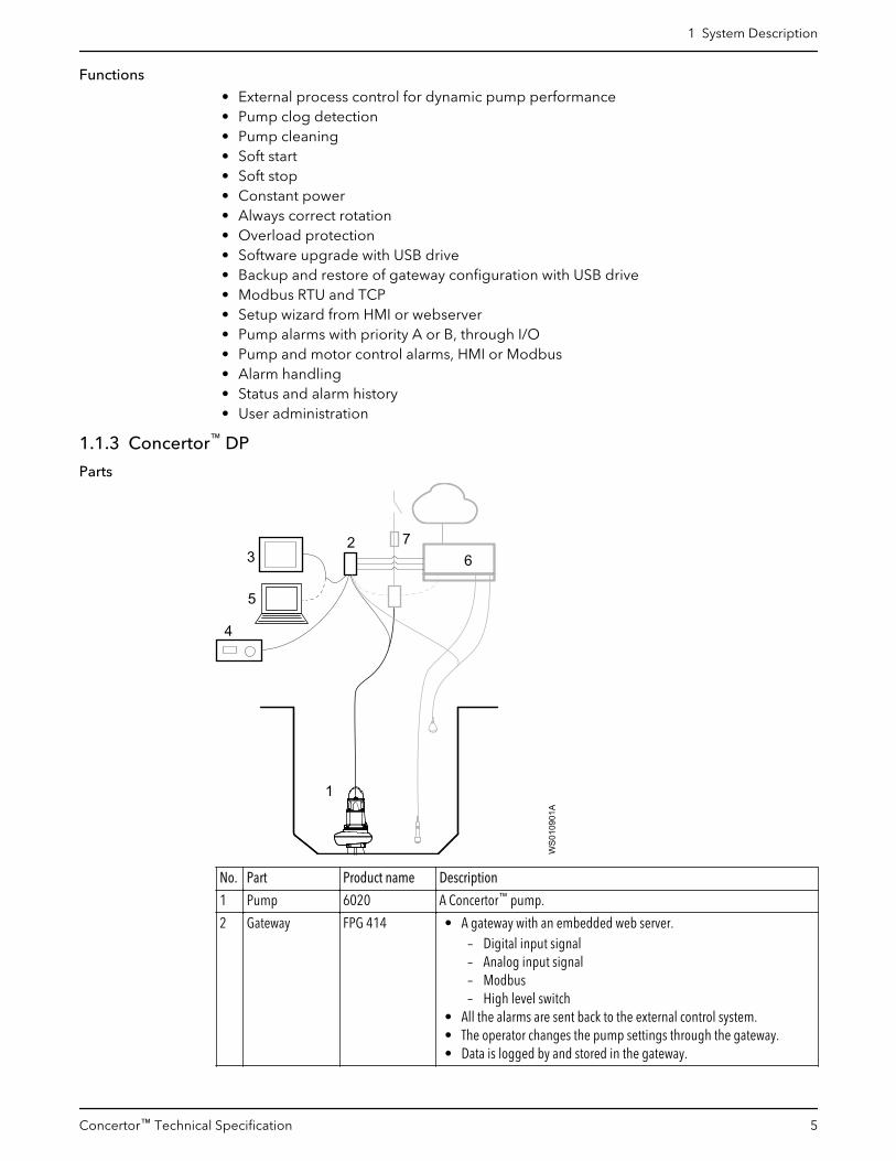
1.1.3 Concertor™ DP
Parts
3
4
5
WS0
1090
1A2
67
1
No. Part Product name Description
1 Pump 6020 A Concertor™ pump.
2 Gateway FPG 414 • A gateway with an embedded web server.– Digital input signal– Analog input signal– Modbus– High level switch
• All the alarms are sent back to the external control system.• The operator changes the pump settings through the gateway.• Data is logged by and stored in the gateway.
1 System Description
Concertor™ Technical Specification 5

No. Part Product name Description
3 HMI FOP 402 HMI - Alternative 1• A touchscreen HMI that is used for navigation and selection in the
menus.• The touchscreen HMI is connected to a web server that is embedded
in the gateway.
4 HMI FOP 315 HMI - Alternative 2• A basic HMI with a jog wheel that is used for navigation and selection
in the menus.
5 Computer – HMI - Alternative 3• The computer gives access to the same menu system as the
touchscreen HMI.• The computer is connected to a web server that is embedded in the
gateway.
6 Connectivityoptions
– • Controller / RTU / PLC• Level sensors• Cloud services
7 Connection topower
– Contactors, fuses, relays
Functions
• External process control for dynamic pump performance• Pump clog detection• Pump cleaning• Soft start• Soft stop• Constant power• Always correct rotation• Overload protection• Software upgrade with USB drive• Backup and restore of gateway configuration with USB drive• Modbus RTU and TCP• Setup wizard from HMI or webserver• Pump alarms with priority A or B, through I/O• Pump and motor control alarms, HMI or Modbus• Alarm handling• Status and alarm history• User administration
1 System Description
6 Concertor™ Technical Specification

1.1.4 Concertor™ XPC
Parts
1
26
7
5
43
WS0
1109
5A
8
9
No. Part Product name Description
1 Pump 6020 A Concertor™ pump.
2 Controller APP 411 • The controller starts and stops the pump based on inputsignals from, for example, level sensors and high-levelswitches.
• The operator changes the pump settings through the localHMI or through a SCADA system over Modbus.
• Data is logged by and stored in the controller.• All the alarms are available on the local HMI and Modbus.• System communication through the backplane.
3 Gateway FPG 414 A gateway that is controlled by the APP 411.• System communication through the backplane.• All the alarms and data are sent to the controller.
4 HMI FOP 402 HMI - Alternative 1• A touchscreen HMI that is used for navigation and selection
in the menus.• The touchscreen HMI is connected to a web server that is
embedded in the controller.
5 HMI FOP 315 HMI - Alternative 2• A basic HMI with a jog wheel that is used for navigation and
selection in the menus.
6 Computer – HMI - Alternative 3• The computer gives access to the same menu system as the
touchscreen HMI.• The computer is connected to a web server that is embedded
in the controller.
7 Level sensors – • Analog sensor• Digital switch
8 Cloud connection – Cloud services
9 Connection to power – Contactors, fuses, relays
1 System Description
Concertor™ Technical Specification 7

Functions
Pump control functions
• Pump station management• Setup wizard from HMI or webserver• Soft start• Soft stop• Always correct rotation• Overload protection• Hand-Off-Auto control from the HMI• Pump alternation• High inflow operation• Energy minimizer• Maximum pump cycle time• Overflow protection• Redundancy mode• Pipe flush start• Maintenance run
Cleaning functions
• Pump clog detection• Pump cleaning• Sump cleaning, with snoring sensitivity• Pipe cleaning• Grease stripe minimization
Alarm and information functions
• Alarm handling• Sum alarm with priority level A and B indication, LED and digital output• Individual alarm indication, HMI or Modbus• Status information and alarm history• Station and pump alarms• Software upgrade with USB drive• Backup and restore of gateway and controller configuration with USB drive• Modbus RTU and TCP• Backplane communication• Overflow alarm and statistics• User administration
1 System Description
8 Concertor™ Technical Specification

2 Product Description2.1 N-pump2.1.1 Pump design
The pump is submersible and based on the Dirigo™ platform, that consists of a controlsystem and a permanent-magnet synchronous motor. For motor data, see TechnicalReference on page 16.
Impeller material
• Gray iron• Hard-Iron™
• Stainless steel
Pressure class, discharge connection
LT/150 Low head
MT/100 Medium head
HT/80 High head
Installation types
The pump can be used in the following installations:
P Semipermanent, wet well arrangement with the pump installed on two guide bars. Theconnection to the discharge is automatic.
S Portable semipermanent, wet well arrangement with hose coupling or flange forconnection to the discharge pipeline.
T Vertical permanent, dry well arrangement with flange connection to the suction anddischarge piping.
Z Horizontal permanent, dry well arrangement with flange connection to the suction anddischarge piping.
Products included
Product Approvals
6020.180 Standard
6020.090 Ex-approved
2 Product Description
Concertor™ Technical Specification 9

Illustrations
WS0
0998
7B
8
10
11
12
13
95
4
3
14
2
1
6
7
Figure 1: Outer casing of drive unit: Gray iron
2 Product Description
10 Concertor™ Technical Specification

WS0
0976
7B
8
10
11
12
13
95
4
3
14
2
1
6
7
Figure 2: Outer casing of drive unit: Aluminum
Parts
Position Part
1 Insert ring with a guide pin
2 Pump housing, without flush valve connection
3 Seal housing cover
4 Stator housing unit with a leakage sensor
5 Cooling jacket/ outer casing
6 Connection housing with integrated control system
7 Lifting handle
8 Cable entry
9 Support bearing
10 Shaft unit with a permanent magnet rotor
11 Main bearing
2 Product Description
Concertor™ Technical Specification 11

Position Part
12 Mechanical sealPlug in seal with active seal design.
13 Adaptive-N impeller
14 Oil
2.1.2 CablesScreened Flygt SUBCAB® - a heavy duty 4 screened cores motor power cable with fourtwisted pair screened control cores. Conductor insulation rating of 90°C, which allows forincreased current. Superior mechanical strength and high abrasion and tear resistant.Chemical resistant within pH 3-10 and ozone, oil, and flame resistant. Used up to 70°Cwater temperature.
2.1.3 Monitoring equipment• Leakage sensor in the stator housing (FLS)• Overtemperature sensors in the control system
Explosion-proof version: The stator incorporates three thermal contacts connected inseries.
2.1.4 Options• Surface treatment (Epoxy)• Zinc anodes
2.1.5 AccessoriesExample of accessories.
Item Description
Pump controllers FGC 400, MultiSmart, MyConnect
HMI FOP 315, FOP 402
Monitoring relays Supplied locally
Level sensors LTU, ENM 10
SCADA systems AquaView
Flow meters MagFlux
Discharge connections, adapters, hose connections, and other mechanical accessories
2.2 FPG 413, FPG 414, APP4112.2.1 Product design
The product is part of the Concertor™ system.
Product name Part number Description
FPG 413 8156500 Gateway for Concertor™ EA.The pump performance is easily adjustable when the pump isstopped.
FPG 414 8164700 Gateway for Concertor™ DP or Concertor™ XPC.Dynamic pump performance change, through 4–20 mA orModbus, or APP 411.
APP 411 8011900 Controller for Concertor™ XPC
2 Product Description
12 Concertor™ Technical Specification

2.2.2 Approvals• CE• UL• CSA• RCM
2.2.3 Parts
PWR
RS485
DI
12
34
GND
A
AI
AO
HMI
12
34
5
BGND
24VDC+_
+_
+_
DI1
DI2
DI3
DI4
DO1DO2DO3DO4
ALARM AALARM BPUMP RUN/CLEANPUMP COMMS
RS485
USB
NODEADDRESSONOFF
MASTERSLAVE
TER
M
PUMP
DO1NOCOM
NOCOM
T4T3
GND
DO2DO3NO
COMNO
COM
DO4ETHERNET
WS0
1129
8A
4
7
8
3
9 0
6
12
5
4
3
2
1Concertor™
PWR
RS485
DI
12
34
GND
A
AI
AO
HMI
12
34
5
BGND
24VDC+_
+_
+_
DI1
DI2
DI3
DI4
DO1DO2DO3DO4
ALARM AALARM BPUMP RUN/CLEANPUMP COMMS
RS485
USB
NODEADDRESSONOFF
MASTERSLAVE
TER
M
PUMP
DO1NOCOM
NOCOM
T4T3
GND
DO2DO3NO
COMNO
COM
DO4ETHERNET
WS0
0974
7C
4
7
8
3
9 0
6
12
5
4
3
2
1Concertor™
5
1. Front connections2. Status LEDs3. Top connections4. Bottom connections5. Backplane connector
2.3 FOP 4022.3.1 Product design
FOP 402 is a touchscreen HMI that is connected to one or more web servers.
The HMI is installed on a wall or in the cabinet door.
Product name Article number Description
FOP 402 822 48 00
2.3.2 Approvals• CE• UL
2 Product Description
Concertor™ Technical Specification 13

2.3.3 Parts
WS0
1090
4A
21
1. Terminals, see Terminals on page 252. Screen
2.4 FOP 3152.4.1 Product design
The FOP 300 series are HMI units that are connected to a Flygt gateway or controller toprovide a user-friendly interface. For information on how to use the HMI, see theInstallation, Operation, and Maintenance manuals for the related products or the SystemInstallation and Operation manual.
The HMI is handheld, or mounted in or on a cabinet door, or inside a cabinet.
Product name Article number Description
FOP 315 823 88 00 • Hand/Off/Auto for between one and eight mixers orpumps
• One set of Hand, Off, Auto buttons
2.4.2 Approvals• CE• CSA• UL
2 Product Description
14 Concertor™ Technical Specification
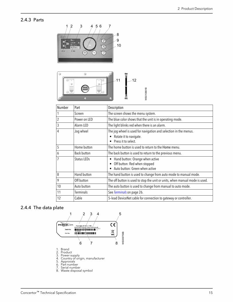
2.4.3 Parts2 31 4 5 6 7
WS0
1086
1B
11 12
8910
Number Part Description
1 Screen The screen shows the menu system.
2 Power on LED The blue color shows that the unit is in operating mode.
3 Alarm LED The light blinks red when there is an alarm.
4 Jog wheel The jog wheel is used for navigation and selection in the menus.• Rotate it to navigate.• Press it to select.
5 Home button The home button is used to return to the Home menu.
6 Back button The back button is used to return to the previous menu.
7 Status LEDs • Hand button: Orange when active• Off button: Red when stopped• Auto button: Green when active
8 Hand button The hand button is used to change from auto mode to manual mode.
9 Off button The off button is used to stop the unit or units, when manual mode is used.
10 Auto button The auto button is used to change from manual to auto mode.
11 Terminals See Terminals on page 26.
12 Cable 5–lead DeviceNet cable for connection to gateway or controller.
2.4.4 The data plate2 3 4 5
6 7 8
1
WS0
0975
9B
1. Brand2. Product3. Power supply4. Country of origin, manufacturer5. Approvals6. Part number7. Serial number8. Waste disposal symbol
2 Product Description
Concertor™ Technical Specification 15

3 Technical Reference3.1 N-pump3.1.1 Motor data
The drive unit includes a synchronous motor with IE4 equivalent efficiency.
NOTICE:
Do not connect a starter or a Variable Frequency Drive (VFD) to this unit.
Feature Description
Input frequency 50–60 Hz
Input supply 3-phase• 380–480 V• 200–240 V
Maximum starts per hour Pump only: 60Pump with gateway or controller: 240
Design in applicable parts According to IEC 60034–1
Voltage variation • Continuously running: Maximum ±5%• Intermittently running: Maximum ±10%
Voltage imbalance between the phases Maximum of 2%
Stator insulation class In accordance with class H (180°C, 356°F)
3.1.2 Application limits
Data Description
Liquid temperature Maximum 40°C (104°F)
Liquid density Maximum 1100 kg/m3 (9.2 lb per US gal)
pH of the pumped liquid 5.5–14
Depth of immersion Maximum 20 m (65 ft)
3.1.3 Materials
Table 1: Major parts except mechanical seals
Denomination Material ASTM EN
Major castings Cast iron, gray 35B GJL-250
Cooling jacket, alternative 1 Cast iron, gray 35B GJL-250
Cooling jacket, alternative 2 Aluminum H5202-86-AC4A 1706:AC-43100+43000
Pump housing Cast iron, gray 35B GJL-250
Impeller, alternative 1 Hard-Iron™ A 532 IIIA GJN-HB555(XCR23)
Impeller, alternative 2 Stainless steel, Duplex CD-4MCuN 10283:1.4474
Insert ring Cast iron, Hard-Iron™ A 532 IIIA GJN-HB555(XCR23)
Lifting handle Stainless steel AISI 316L 1.4404,1.4432, …
Shaft Stainless steel AISI 431 1.4057+QT800
Screws and nuts Stainless steel, A4 AISI 316L, 316, 316Ti 1.4401,1.4404, …
O-rings Nitrile rubber (NBR) 70°IRH
- -
3 Technical Reference
16 Concertor™ Technical Specification

Denomination Material ASTM EN
Oil A medical white oil ofparaffin type that fulfillsFDA 172.878 (a) andviscosity close to VG32.
- -
Table 2: Mechanical seals
Alternative Inner seal Outer seal
1 Corrosion resistant cemented carbide (WCCR)/Corrosion resistant cemented carbide (WCCR)
Corrosion resistant cemented carbide(WCCR)/ Corrosion resistant cementedcarbide (WCCR)
2 Corrosion resistant cemented carbide (WCCR)/Corrosion resistant cemented carbide (WCCR)
Silicon carbide (RSiC)/ Silicon carbide(RSiC)
3.1.4 Surface treatment
Priming Finish
Painted with a primer, see internal standardM0700.00.0002
Navy gray color NCS 5804-B07G. Two-component high-solid top coating, see internal standard M0700.00.0004for standard painting and M0700.00.0008 for specialpainting.
3.2 FPG 413, FPG 414, APP4113.2.1 Dimensions
RS485DI1 2 3 4 GND A
AI AO HMI1 2 3 4 5
B GND
24VDC+ _
+ _ + _
PWR
DI1
DI2
DI3
DI4
DO1
DO2
DO3
DO4
ALARM A
ALARM B
PUMP RUN/CLEAN
PUMP COMMS
RS485
USB
NODEADDRESS
ON
OFF
MASTER
SLAVETER
M
PUMP
DO1NO COM NO COM
T4 T3 GND
DO2
DO3NO COM NO COM
DO4
ETHERNET
1 2 3 4 5 6 7
8
9 0
1 2
3
WS0
0974
6BConcertor™
1. 112 mm (4.4 in)2. 45 mm (1.8 in)3. 106 mm (4.2 in)
3.2.2 Environmental requirements
Parameter Value
Operating temperature -20°C – +65°C (-4°F – 149°F)
Storage temperature -20°C – +70°C (-4°F – 158°F)
Operating humidity Relative humidity, non-condensing: 5 – 95%
Sunlight exposure UV-resistant
Maximum altitude • With UL approval: Maximum 2000 m (6562 ft)• Without UL approval: 4000 m (13 123 ft)
3.2.3 IP-ratingIP20
3 Technical Reference
Concertor™ Technical Specification 17

3.2.4 Electrical data
Parameter Value
Supply voltage + 24 VDC
Supply voltage tolerance 21.5–28.5 VDC
Current consumption < 700 mA. Typical: 150 mA
3.2.5 Terminals FPG 413
PWR
RS485
DI
12
34
GND
A
AI
AO
HMI
12
34
5
BGND
24VDC+_
+_
+_
DI1
DI2
DI3
DI4
DO1DO2DO3DO4
ALARM AALARM BPUMP RUN/CLEANPUMP COMMS
RS485
USB
NODEADDRESSONOFF
MASTERSLAVE
TER
M
PUMP
DO1NOCOM
NOCOM
T4T3
GND
DO2DO3NO
COMNO
COM
DO4ETHERNET
4
7
8
3
9 0
6
12
5
12
43 WS0
0974
9C
7 8 9 1310 11 12
56
Concertor™
14
Section Terminal Default Description
1 NODE ADDRESS 1 Node address0–9, rotary switch. 0 is not used.
2 TERM – Backplane termination switch
3 USB – Standard type A USB socket
4 MASTER, SLAVE – MASTER: Always applicable.SLAVE: Not applicable for FPG 413
5 AI + None Isolated analog input, 4–20 mAMaximum 24 VDCNot applicable for FPG 413
–
AO + Speed Analog output, 4–20 mAMaximum 24 VDCThe output is configurable:• None• Speed, shaft• Power, the input power of the motor• Current, the input current of the motor
–
6 DI 1 Call to run Digital inputsMaximum 24 VDCThe inputs are configurable:• Call to run• Acknowledge alarms• Hand• Auto• None• High level switch
2 Acknowledgealarms
3 High level switch
4 None
GND – Common ground (earth)
3 Technical Reference
18 Concertor™ Technical Specification

Section Terminal Default Description
7 HMI• Flygt FOP 315
1 – Ground
2 CAN low
3 Shield
4 CAN high
5 + 24 VDC output
8 RS-485 A – Modbus RTU
B
GND
9 24 VDC + – 24 VDCTolerance: 21.5–28.5 VDCThe power supply unit must fulfill isolationclass II.< 700 mA. Typical: 150 mAFuse: 1 A
–
10 DO3 NO Class B alarmstatus
Digital outputsPotential free relay outputMaximum 250 VAC, or 30 VDC, 5 AExternal fuse required, 5 AThe outputs are configurable:• None• Class A alarm status• Class B alarm status• Sum alarm status• Pump running• Pump cleaning• Energized unit
Logic:• Normally open• Normally closed
COM
DO4 NO Energized unit
COM
11 DO1 NO Pump running
COM
DO2 NO Class A alarmstatusCOM
12 PUMP T4 – Pump communication
T3
GND – Not used
13 Ethernet – • Modbus TCP• Web server
14 Backplane – Not applicable
3 Technical Reference
Concertor™ Technical Specification 19
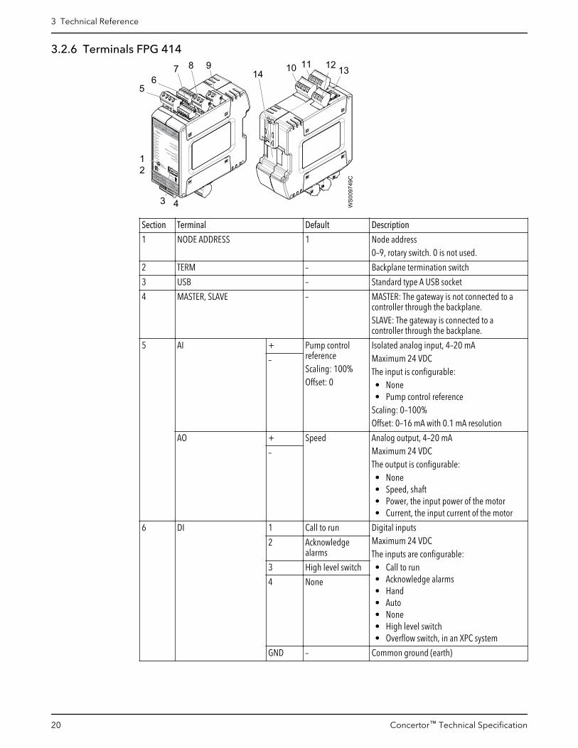
3.2.6 Terminals FPG 414
PWR
RS485
DI
12
34
GND
A
AI
AO
HMI
12
34
5
BGND
24VDC+_
+_
+_
DI1
DI2
DI3
DI4
DO1DO2DO3DO4
ALARM AALARM BPUMP RUN/CLEANPUMP COMMS
RS485
USB
NODEADDRESSONOFF
MASTERSLAVE
TER
M
PUMP
DO1NOCOM
NOCOM
T4T3
GND
DO2DO3NO
COMNO
COM
DO4ETHERNET
4
7
8
3
9 0
6
12
5
12
43 WS0
0974
9C
7 8 9 1310 11 12
56
Concertor™
14
Section Terminal Default Description
1 NODE ADDRESS 1 Node address0–9, rotary switch. 0 is not used.
2 TERM – Backplane termination switch
3 USB – Standard type A USB socket
4 MASTER, SLAVE – MASTER: The gateway is not connected to acontroller through the backplane.SLAVE: The gateway is connected to acontroller through the backplane.
5 AI + Pump controlreferenceScaling: 100%Offset: 0
Isolated analog input, 4–20 mAMaximum 24 VDCThe input is configurable:• None• Pump control reference
Scaling: 0–100%Offset: 0–16 mA with 0.1 mA resolution
–
AO + Speed Analog output, 4–20 mAMaximum 24 VDCThe output is configurable:• None• Speed, shaft• Power, the input power of the motor• Current, the input current of the motor
–
6 DI 1 Call to run Digital inputsMaximum 24 VDCThe inputs are configurable:• Call to run• Acknowledge alarms• Hand• Auto• None• High level switch• Overflow switch, in an XPC system
2 Acknowledgealarms
3 High level switch
4 None
GND – Common ground (earth)
3 Technical Reference
20 Concertor™ Technical Specification

Section Terminal Default Description
7 HMI• Flygt FOP 315
1 – Ground
2 CAN low
3 Shield
4 CAN high
5 + 24 VDC output
8 RS-485 A – Modbus RTU
B
GND
9 24 VDC + – 24 VDCTolerance: 21.5–28.5 VDCThe power supply unit must fulfill isolationclass II.< 700 mA. Typical: 150 mAFuse: 1 A
–
10 DO3 NO Class B alarmstatus
Digital outputsPotential free relay outputMaximum 250 VAC, or 30 VDC, 5 AExternal fuse required, 5 AThe outputs are configurable:• None• Class A alarm status• Class B alarm status• Sum alarm status• Pump running• Pump cleaning• Energized unit
Logic:• Normally open• Normally closed
COM
DO4 NO Energized unit
COM
11 DO1 NO Pump running
COM
DO2 NO Class A alarmstatusCOM
12 PUMP T4 – Pump communication
T3
GND – Not used
13 Ethernet – • Modbus TCP• Web server
14 Backplane – Concertor™ XPCThe controller communicates with thegateways through the backplane.
3 Technical Reference
Concertor™ Technical Specification 21

3.2.7 Terminals APP 411
PWR
RS485
DI
12
34
GND
A
AI
AO
HMI
12
34
5
BGND
24VDC+_
+_
+_
DI1
DI2
DI3
DI4
DO1DO2DO3DO4
ALARM AALARM BPUMP RUN/CLEANPUMP COMMS
RS485
USB
NODEADDRESSONOFF
MASTERSLAVE
TER
M
PUMP
DO1NOCOM
NOCOM
T4T3
GND
DO2DO3NO
COMNO
COM
DO4ETHERNET
4
7
8
3
9 0
6
12
5
12
43 WS0
0974
9C
7 8 9 1310 11 12
56
Concertor™
14
Section Terminal Default Description
1 NODE ADDRESS 1 Node address0–9, rotary switch. 0 is not used.
2 TERM – Backplane termination switch
3 USB – Standard type A USB socket
4 MASTER, SLAVE – Always MASTER
5 AI + None Isolated analog input, 4–20 mAMaximum 24 VDCThe input is configurable:• None• Water level
–
AO + Water level Analog output, 4–20 mAMaximum 24 VDCThe output is configurable:• None• Speed, shaft• Power, the input power of the motor• Current, the input current of the motor• Water level
–
6 DI 1 None Digital inputsMaximum 24 VDCThe inputs are configurable:• None• Acknowledge alarms• Hand• Auto• High level switch• Overflow switch
2 Acknowledgealarms
3 High level switch
4 None
GND – Common ground (earth)
7 HMI• Flygt FOP 315
1 – Ground
2 CAN low
3 Shield
4 CAN high
5 + 24 VDC output
3 Technical Reference
22 Concertor™ Technical Specification

Section Terminal Default Description
8 RS-485 A – Modbus RTU
B
GND
9 24 VDC + – 24 VDCTolerance: 21.5–28.5 VDCThe power supply unit must fulfill isolationclass II.< 700 mA. Typical: 150 mAFuse: 1 A
–
10 DO3 NO Class B alarmstatus
Digital outputsPotential free relay outputMaximum 250 VAC, or 30 VDC, 5 AExternal fuse required, 5 AThe outputs are configurable:• None• Class A alarm status• Class B alarm status• Sum alarm status• Pump running• Pump cleaning
Logic:• Normally open• Normally closed
COM
DO4 NO None
COM
11 DO1 NO Pump running
COM
DO2 NO Class A alarmstatusCOM
12 PUMP T4 – Pump communication
T3
GND – Not used
13 Ethernet – • Modbus TCP• Web server
14 Backplane – The controller communicates with thegateways through the backplane.
3 Technical Reference
Concertor™ Technical Specification 23

3.3 FOP 4023.3.1 Dimensions
3.05
mm
(0
.12
in)
36.5 mm(1.44 in)
5.7 mm (0.22 in)
128.
4 m
m (5
.06
in)
197 mm (7.76 in)
140
mm
(5.5
in)
185.4 mm (7.30 in)
10.5
mm
(0.4
1 in
)
WS010903A
3.3.2 Environmental requirements
Parameter Value
Operating temperature -20°C – +60°C (-4°F – +140°F)
Storage temperature -30°C – +80°C (-22°F – +176°F)
Operating humidity Relative humidity: 20–90 %
3.3.3 IP-rating• IP20, back side• IP65, front side
3.3.4 Electrical data
Parameter Value
Supply voltage 24 VDC
Maximum current at nominal voltage 0.35 A at 24 VDC
Maximum power consumption 8.5 W
Voltage range 24 VDC (-15% / +20%)
3.3.5 Display data
Part Description
Processor ARM Cortex A9, dual core, 800 MHz
Display 7” TFT LED, resolution 800 x 480 pixels
Brightness 500 cd/m2
Contrast ratio 600:1
Colors 16.7 M
3 Technical Reference
24 Concertor™ Technical Specification

Part Description
Touch-panel type Multi-touch, PCT
Memory 512 MB Flash, 1 GB RAM
3.3.6 Terminals
WS0
1090
5A
1 2 3 4
Number Terminal Description
1 Ethernet -
2 USB The HMI is equipped with a USB 2.0host controller with two USBinterfaces.
3 Power supply 24 VDC
4 Grounding clip -
3.4 FOP 3153.4.1 Dimensions
33 mm (1.3 in)
47 m
m (1
.9 in
)WS010860B
205 mm (8.1 in)11
0 m
m (4
.3 in
)
3.4.2 Environmental requirements
Parameter Value
Operating temperature -20°C – +70°C (-4°F – 158°F)
Storage temperature -20°C – +85°C (-4°F – 185°F)
Operating humidity Relative humidity, non-condensing: 90%
Sunlight exposure UV resistant, avoid direct sunlight
3.4.3 IP-rating
Installation IP-rating
On a cabinet door Front: IP54. Back: IP21
In a cabinet door Front: IP54. Back: IP21
• DIN rail• Hand-held
IP20
3.4.4 Electrical data
Parameter Value
Supply voltage 24 VDC
3 Technical Reference
Concertor™ Technical Specification 25

Parameter Value
Supply voltage tolerance ± 10%
Current consumption < 100 mA
3.4.5 Terminals
WS0
0965
0A
1 2 3 4 5
Number Terminal Description Cable color
1 GND Ground (earth), 0 V Black
2 L CAN low Blue
3 — Screen. Not used. Transparent
4 H CAN high White
5 +24 V Power supply, +24 V Red
The power supply unit must fulfill isolation class II.
3 Technical Reference
26 Concertor™ Technical Specification

4 Motor Rating and PerformanceCurves4.1 Motor rating380–480 V
Rated power(kW)
Rated power(Hp)
Voltage (V) / Rated current(A)
Voltage (V) / Startingcurrent (A)
Power factor Installation
7.3 10.0 380/13.1 - 480/10.4 380/13.1 - 480/10.4 0.95 P, S
5.5 7.5 380/10.0 - 480/7.9 380/10.0 - 480/7.9 0.95 P, S, T, Z
4.0 5.5 380/7.5 - 480/5.9 380/7.5 - 480/5.9 0.94 P, S, T, Z
2.2 3.0 380/4.6 - 480/3.7 380/4.6 - 480/3.7 0.91 P, S, T, Z
200–240 V
Rated power(kW)
Rated power(Hp)
Voltage (V) / Rated current(A)
Voltage (V) / Startingcurrent (A)
Power factor Installation
4.0 5.5 200/14 - 240/11.7 200/14 - 240/11.7 0.95 P, S, T, Z
2.2 3.0 200/7.3 - 240/6.1 200/7.3 - 240/6.1 0.95 P, S, T, Z
4 Motor Rating and Performance Curves
Concertor™ Technical Specification 27

4.2 Performance curves150 (LT)
The image shows the available field of operation, and maximum revolutions per minute(rpm) for each rated power value.
0 20 40 60 80 100 1200
2
4
6
8
10
12
14
16
Flow [l/s]
Hea
d [m
]
0 200 400 600 800 1000 1200 1400 1600 1800
0
5
10
15
20
25
30
35
40
45
50
Flow [US gpm]
Hea
d [ft
]
0 20 40 60 80 100 1200
1
2
3
4
5
6
2.2kW / 3Hp / 1200 rpm
4.0kW / 5.5Hp / 1400 rpm
5.5kW / 7.5Hp / 1600 rpm
Flow [l/s]
Shaf
t pow
er [k
W]
0 200 400 600 800 1000 1200 1400 1600 1800
0
1
2
3
4
5
6
7
8
Flow [US gpm]
Shaf
t pow
er [H
p]
WS0
1000
0B
2.2kW / 3Hp / 1200 rpm
4.0kW / 5.5Hp / 1400 rpm
5.5kW / 7.5Hp / 1600 rpm
4 Motor Rating and Performance Curves
28 Concertor™ Technical Specification

100 (MT)
The image shows the available field of operation, and maximum revolutions per minute(rpm) for each rated power value.
WS0
1000
1A
0 10 20 30 40 50 60 70 80 900
5
10
15
20
25
30
Flow [l/s]
Hea
d [m
]
0 200 400 600 800 1000 1200 1400
0
10
20
30
40
50
60
70
80
90
Flow [US gpm]
Hea
d [ft
]
0 10 20 30 40 50 60 70 80 900
1
2
3
4
5
6
7
8
2.2kW / 3Hp / 1500 rpm
4.0kW / 5.5Hp / 1800 rpm
5.5kW / 7.5Hp / 2000 rpm
7.3kW / 10Hp / 2200 rpm
Flow [l/s]
Shaf
t pow
er [k
W]
0 200 400 600 800 1000 1200 1400
0
1
2
3
4
5
6
7
8
9
10
Flow [US gpm]
Shaf
t pow
er [H
p]
2.2kW / 3Hp / 1500 rpm
4.0kW / 5.5Hp / 1800 rpm
5.5kW / 7.5Hp / 2000 rpm
7.3kW / 10Hp / 2200 rpm
4 Motor Rating and Performance Curves
Concertor™ Technical Specification 29

80 (HT)
The image shows the available field of operation, and maximum revolutions per minute(rpm) for each rated power value.
WS0
1000
2A
0 5 10 15 20 25 30 35 40 450
1
2
3
4
5
6
7
8
2.2kW / 3Hp / 2100 rpm
4.0kW / 5.5Hp / 2600 rpm
5.5kW / 7.5Hp / 2900 rpm
7.3kW / 10Hp / 3300 rpm
Flow [l/s]
Shaf
t pow
er [k
W]
0 100 200 300 400 500 600 700
0
1
2
3
4
5
6
7
8
9
10
Flow [US gpm]
Shaf
t pow
er [H
p]
0 5 10 15 20 25 30 35 40 450
5
10
15
20
25
30
35
40
45
50
Flow [l/s]
Hea
d [m
]
0 100 200 300 400 500 600 700
0
20
40
60
80
100
120
140
160
Flow [US gpm]
Hea
d [ft
]
2.2kW / 3Hp / 2100 rpm
4.0kW / 5.5Hp / 2600 rpm
5.5kW / 7.5Hp / 2900 rpm
7.3kW / 10Hp / 3300 rpm
4 Motor Rating and Performance Curves
30 Concertor™ Technical Specification
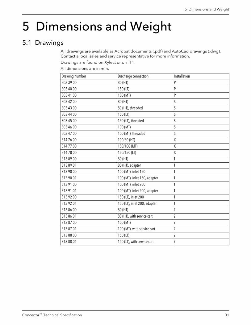
5 Dimensions and Weight5.1 Drawings
All drawings are available as Acrobat documents (.pdf) and AutoCad drawings (.dwg).Contact a local sales and service representative for more information.
Drawings are found on Xylect or on TPI.
All dimensions are in mm.
Drawing number Discharge connection Installation
803 39 00 80 (HT) P
803 40 00 150 (LT) P
803 41 00 100 (MT) P
803 42 00 80 (HT) S
803 43 00 80 (HT), threaded S
803 44 00 150 (LT) S
803 45 00 150 (LT), threaded S
803 46 00 100 (MT) S
803 47 00 100 (MT), threaded S
814 76 00 100/80 (HT) X
814 77 00 150/100 (MT) X
814 78 00 150/150 (LT) X
813 89 00 80 (HT) T
813 89 01 80 (HT), adapter T
813 90 00 100 (MT), inlet 150 T
813 90 01 100 (MT), inlet 150, adapter T
813 91 00 100 (MT), inlet 200 T
813 91 01 100 (MT), inlet 200, adapter T
813 92 00 150 (LT), inlet 200 T
813 92 01 150 (LT), inlet 200, adapter T
813 86 00 80 (HT) Z
813 86 01 80 (HT), with service cart Z
813 87 00 100 (MT) Z
813 87 01 100 (MT), with service cart Z
813 88 00 150 (LT) Z
813 88 01 150 (LT), with service cart Z
5 Dimensions and Weight
Concertor™ Technical Specification 31

WS1
0491
A
Figure 3: DN 150 (LT)
5 Dimensions and Weight
32 Concertor™ Technical Specification

WS1
0492
A
Figure 4: DN 100 (MT)
5 Dimensions and Weight
Concertor™ Technical Specification 33

WS1
0493
A
Figure 5: DN 80 (HT)
5 Dimensions and Weight
34 Concertor™ Technical Specification


Xylem |’zīləm|
1) The tissue in plants that brings water upward from the roots;2) a leading global water technology company.
We’re a global team unified in a common purpose: creating advancedtechnology solutions to the world’s water challenges. Developing newtechnologies that will improve the way water is used, conserved, and re-used inthe future is central to our work. Our products and services move, treat, analyze,monitor and return water to the environment, in public utility, industrial,residential and commercial building services settings. Xylem also provides aleading portfolio of smart metering, network technologies and advancedanalytics solutions for water, electric and gas utilities. In more than 150 countries,we have strong, long-standing relationships with customers who know us for ourpowerful combination of leading product brands and applications expertise witha strong focus on developing comprehensive, sustainable solutions.
For more information on how Xylem can help you, go to www.xylem.com
The original instruction is in English. All non-Englishinstructions are translations of the original instruction.
© 2018 Xylem Inc
888088_3.0_en-US_2018-10_TS_Concertor™
[email protected] Tel. +31-152-610-900www.lenntech.com Fax. [email protected] Tel. +31-152-610-900www.lenntech.com Fax. +31-152-616-289
Lenntech


