
Componentsfor industrial communication
Lenze Global Drive – Providing the connection

Modular
Modular machine and system engineeringis becoming increasingly more important.It has meant that individual solutions cannow be set up cost-effectively from asingle modular system. Many systems usefieldbuses to ensure that the machinesachieve optimum performance when theyare subsequently integrated in completesystems.
Lenze offers a large number of com-munication modules for a wide range ofstandard fieldbuses, which are specificallytailored to Lenze drive controllers. Thesame modules can be used for both servoand frequency inverters, so you will only
need to familiarise yourself with a systemonce. The modules are always handled inthe same way, so once you have learnedhow to use them you will be able to reusethat knowledge many times. This reducestraining requirements, shortens projectplanning times and lowers the overallcosts.
The illustration shows a sample net-work with a Lenze system bus (CAN).This type of network design enables theparticipating stations to exchange datawith each other without the added complication of a control system.
2
Communication components
8200 motecmotor inverter
8200 vectorfrequency inverter
PC
starttecmotor starter
9300 vectorfrequency inverter
3
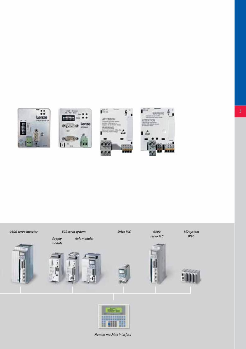
9300 servo inverter Drive PLC I/O system IP20
ECS servo system
Supplymodule
Axis modules
Human machine interface
9300servo PLC
Lenze is a one-stop-shop for all your drive
and automation technology needs and we
can tailor everything to suit your exact
requirements. Today, all industries expect
production systems to combine high pre-
cision and flexibility in the production
process with high speed. In order to meet
these targets, drive controllers must be
integrated into factories' control environ-
ments. These drive controllers not only
communicate with master controls, but
also use bus connections to exchange
data with each other.
Partnership Let us help you find a drive solution
4
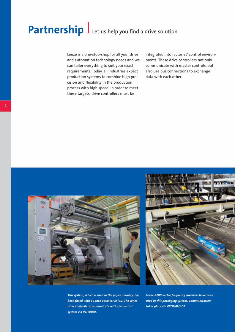
This system, which is used in the paper industry, has
been fitted with a Lenze 9300 servo PLC. The Lenze
drive controllers communicate with the control
system via INTERBUS.
Lenze 8200 vector frequency inverters have been
used in this packaging system. Communication
takes place via PROFIBUS DP.
Every fieldbus system has its own indivi-
dual strengths, so the choice of fieldbus
may vary from industry to industry, and in
some cases from application to applicati-
on. In practice this may mean that diffe-
rent fieldbus systems are operated in par-
allel within the same system. By selecting
the right combination of fieldbus systems,
you can optimise their many benefits in
your own applications.
5
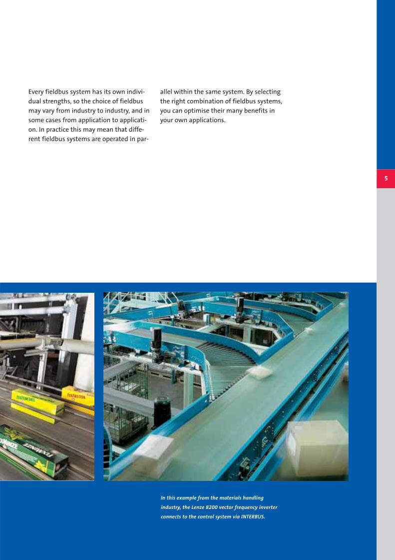
In this example from the materials handling
industry, the Lenze 8200 vector frequency inverter
connects to the control system via INTERBUS.

Frequency inverters Communication with the 8200 vector
Thanks to its modular design, the
8200 vector range of frequency inverters
has two different slots where modules
can be integrated. A distinction has been
made between communication modules
and fieldbus function modules.
In the combination shown below, this
modular design enables a fieldbus to be
used whilst simultaneously using digital
and analog signals for open or closed loop
control. As a result, this system is highly
flexible.
6
Fieldbus communicationwith an INTERBUS EMF2113IB communication module
Open and closed loop control via digital or analog signalswith an I/O function module
Z
Z

7
PROFIBUS DPEMF2133IB
With DIP switches for selecting the
address
INTERBUS EMF2113IB
With DIP switches for selecting
the process data and PCP data
size as well as the baud rate;
for connection to the
INTERBUS remote bus
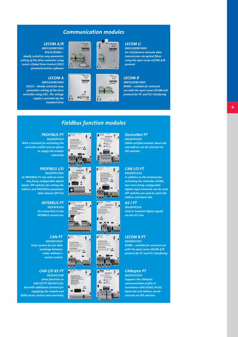
Communication modules
LONEMF2141IB
The fielbus connection commonly
used for building services systems
LECOM A/B EMF2102IBCV001
RS232/RS485 – ideally suited
for easy parameter setting of
the drive controller using Lenze's
Global Drive Control (GDC)
parameterisation software
LECOM B EMF2102IBCV002
RS485 – suitable for universal use
with the open Lenze LECOM A/B
protocol for PC and PLC interfacing
LECOM LI EMF2102IBCV003
For interference-immune data
transmission via optical fibres
using the open
Lenze LECOM A/B protocol
CANEMF2171IB
Lenze system bus supports
CANopen communication
profile parts
CANEMF2172IB
With additional functions
compared to the EMF2171IB:
DIP switches for selecting the
address and baud rate
CANopen/DeviceNetEMF2175IB
With DIP switches for selecting
the address and baud rate and
for selecting the "CANopen"
or "DeviceNet"
communication profile
CANopen*
EMF2178IB
With DIP switches for selecting
the address and baud rate,
compatible with EMF2175IB
DeviceNet*EMF2179IB
With DIP switches for selecting
the address and baud rate,
compatible with EMF2175IB
LECOM A EMF2102IBCV004
RS232 – ideally suited for
easy parameter setting of the
drive controller using GDC.
The voltage supply is provided by
the standard drive
* in preparation
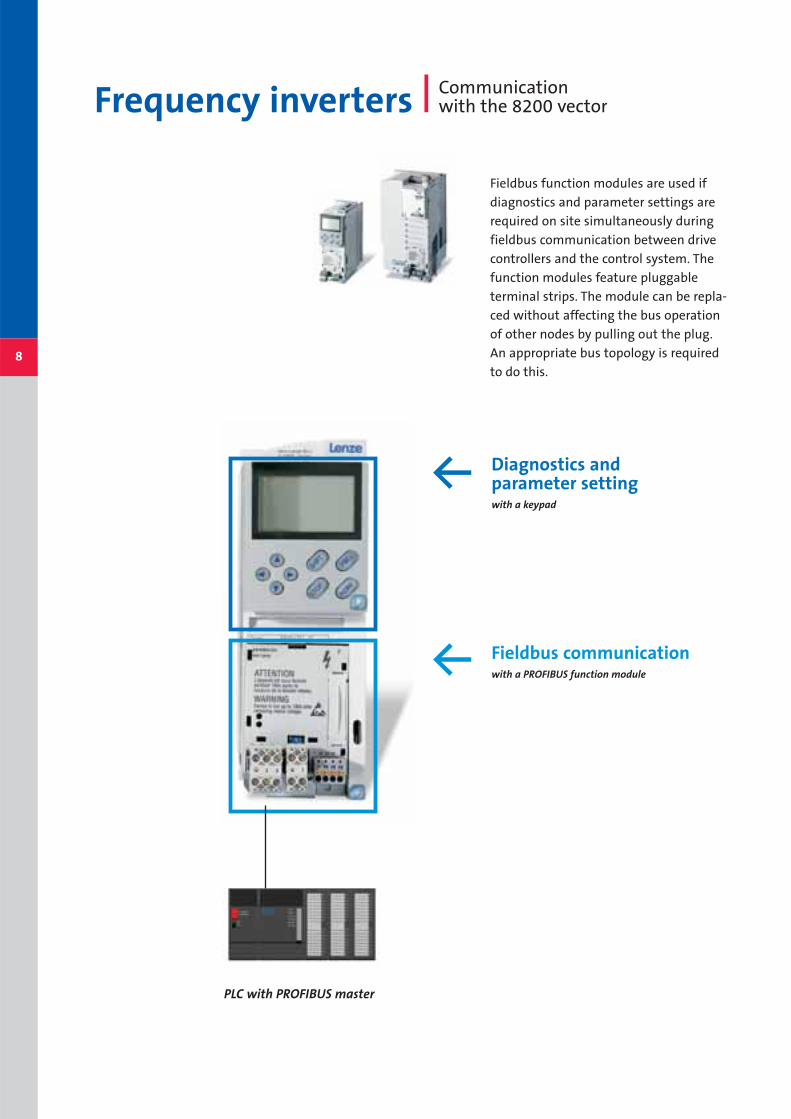
Fieldbus function modules are used if
diagnostics and parameter settings are
required on site simultaneously during
fieldbus communication between drive
controllers and the control system. The
function modules feature pluggable
terminal strips. The module can be repla-
ced without affecting the bus operation
of other nodes by pulling out the plug.
An appropriate bus topology is required
to do this.8
Frequency inverters Communication with the 8200 vector
Fieldbus communicationwith a PROFIBUS function module
Diagnostics and parameter settingwith a keypad
PLC with PROFIBUS master
Z
Z
9
LECOM A/BEMF2102IBCV001
RS232/RS485 –
ideally suited for easy parameter
setting of the drive controller using
Lenze's Global Drive Control (GDC)
parameterisation software
LECOM AEMF2102IBCV004
RS232 – ideally suited for easy
parameter setting of the drive
controller using GDC. The voltage
supply is provided by the
standard drive
Communication modules
LECOM LI EMF2102IBCV003
For interference-immune data
transmission via optical fibres
using the open Lenze LECOM A/B
protocol
PROFIBUS PTE82ZAFPC010
With a terminal for activating the
controller inhibit and an option
to supply the module
externally
INTERBUS PTE82ZAFIC010
For connection to the
INTERBUS remote bus
CAN PTE82ZAFCC010
Lenze system bus for data
exchange between
nodes without a
master control
Fieldbus function modules
AS-i PT E82ZAFFC010
Used to transmit digital signals
via the AS-i bus
LECOM B PTE82ZAFLC010
RS485 – suitable for universal use
with the open Lenze LECOM A/B
protocol for PC and PLC interfacing
CAN I/O PT E82ZAFCC210
In addition to the terminal for
activating the controller inhibit,
two more freely configurable
digital input terminals can be used.
DIP switches are used to select the
address and baud rate.
CAN I/O RS PTE82ZAFCC100
Same functions as
CAN I/O PT E82ZAFC210,
but with additional terminal for
supplying the module and
8200 vector control card externally
CANopen PTE82ZAFUC010
Supports the CANopen
communication profile in
accordance with DS301 V4.02;
baud rate and address can be
selected via DIP switches
DeviceNet PTE82ZAFVC010
ODVA-certified module; baud rate
and address can be selected via
DIP switches
PROFIBUS I/OE82ZAFPCV201
As PROFIBUS PT, but with an extra
two freely configurable digital
inputs, DIP switches for setting the
address and PROFIdrive parameter
data channel (DP-V1)
LECOM B EMF2102IBCV002
RS485 – suitable for universal
use with the open Lenze LECOM A/B
protocol for PC and PLC interfacing

Servo technology
The 9300 servo controller series – with
and without integrated PLC – are available
with various technology packages (posi-
tioning, cam or winding technology).
Communication modules create a link to
master controls. One system bus interface
is integrated as standard. It operates on a
CAN basis, and parts of CANopen are
implemented.
The system bus enables data exchange
between drive controllers, for example in
order to create a master-slave application.
The CAN interface can also be used to
diagnose or parameterise the controllers
at the same time as communication is
taking place with the master control, via a
communication module.
Communication with the 9300 series
10
PROFIBUS DPEMF2133IB
With DIP switches for
selecting the address;
the module is PNO-certified
INTERBUS EMF2113IB
With DIP switches for selecting
the process data and PCP
data size
Integrated system bus based on CAN
Communicat
CANopen/DeviceNetEMF2175IB
With DIP switches for selecting
the address and baud rate and for
selecting the "CANopen"
or "DeviceNet" communication
profile
FP-IEMF2103IB
This module can be used to
control I/O devices via
a freely programmable interface;
however, a Drive PLC or Servo PLC
is required for this functionality
Z
CANopen*
EMF2178IB
With DIP switches for selecting the
address and baud rate,
compatible with EMF2175IB
DeviceNet*EMF2179IB
With DIP switches for selecting the
address and baud rate,
compatible with EMF2175IB
* in preparation
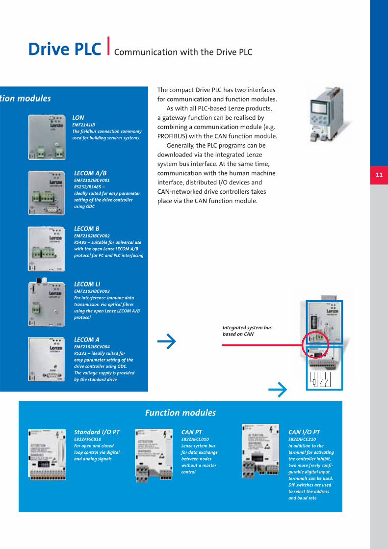
The compact Drive PLC has two interfaces
for communication and function modules.
As with all PLC-based Lenze products,
a gateway function can be realised by
combining a communication module (e.g.
PROFIBUS) with the CAN function module.
Generally, the PLC programs can be
downloaded via the integrated Lenze
system bus interface. At the same time,
communication with the human machine
interface, distributed I/O devices and
CAN-networked drive controllers takes
place via the CAN function module.
Drive PLC Communication with the Drive PLC
11
CAN PTE82ZAFCC010
Lenze system bus
for data exchange
between nodes
without a master
control
Standard I/O PTE82ZAFSC010
For open and closed
loop control via digital
and analog signals
tion modules
Integrated system bus based on CAN
Function modules
LECOM A/B EMF2102IBCV001
RS232/RS485 –
ideally suited for easy parameter
setting of the drive controller
using GDC
LECOM B EMF2102IBCV002
RS485 – suitable for universal use
with the open Lenze LECOM A/B
protocol for PC and PLC interfacing
LECOM LI EMF2102IBCV003
For interference-immune data
transmission via optical fibres
using the open Lenze LECOM A/B
protocol
LECOM A EMF2102IBCV004
RS232 – ideally suited for
easy parameter setting of the
drive controller using GDC.
The voltage supply is provided
by the standard drive
LONEMF2141IB
The fieldbus connection commonly
used for building services systems
Y
Y
CAN I/O PT E82ZAFCC210
In addition to the
terminal for activating
the controller inhibit,
two more freely confi-
gurable digital input
terminals can be used.
DIP switches are used
to select the address
and baud rate

12
The ECS servo system was developed for
gantry systems, robots, packaging machi-
nes and materials handling technology,
and is characterised by high response and
drive performance. The axis modules are
equipped with two system bus interfaces
based on CAN and are therefore tailor-
made for use with centralised control con-
cepts.
The high level of accuracy of multi-axis
movements is achieved by one of the two
system bus interfaces.
Compact servo controllers Communication with the ECS servo system
INTERBUS EMF2113IB
With DIP switches for selecting
the process data
and PCP data size
LECOM A/BEMF2102IBCV001
RS232/RS485 –
ideally suited for easy parameter
setting of the drive controller
using GDC
LECOM LIEMF2102IBCV003
For interference-immune data
transmission via optical fibres
using the open Lenze LECOM A/B
protocol
CANopen/DeviceNetEMF2175IB
With DIP switches for selecting
the address and baud rate and for
selecting the "CANopen" or
"DeviceNet" communication profile
Integrated system bus based on CAN
Z
PROFIBUS DPEMF2133IB
With DIP switches for
selecting the address;
the module is PNO-certified
Communicat
ECS power supply module
* in preparation

13
It transmits synchronised position set-
points with minimum cycle times of
1 ms. Sensors can also be read, diagnosed
and visualised in parallel with "slower"
cycle times via the second system bus,
without affecting data exchange for high-
priority data transmissions.
In addition, the individual servo modu-
les can be addressed via communication
modules for diagnosis with a PC or for
direct communication with a master
control.
LECOM B EMF2102IBCV002
RS485 – suitable for universal
use with the open Lenze
LECOM A/B protocol for PC
and PLC interfacing
LECOM A EMF2102IBCV004
RS232 – ideally suited for easy
parameter setting of the drive
controller using GDC. The voltage
supply is provided by the standard
drive
LONEMF2141IB
The fieldbus connection commonly
used in building services systems
Two integrated systembus interfacesbased on CAN
Y
tion modules
ECS axis module
CANopen*
EMF2178IB
With DIP switches for selecting
the address and baud rate,
compatible with EMF2175IB
DeviceNet*EMF2179IB
With DIP switches for selecting
the address and baud rate,
compatible with EMF2175IB
AS-iE82ZAFFC001
Used to transmit digital signals
(cannot be used with the starttec,
as AS-i is integrated as an option).
Adapters are available for adapting
the AS-i to the motec
PROFIBUSE82ZAFPC001
With a terminal for activating
the controller inhibit and the
option of supplying the module
externally; the module is
PNO-certified
INTERBUSE82ZAFIC001
For connection to the
INTERBUS remote bus
CANopenE82ZAFUC001
Supports the CANopen communi-
cation profile in accordance with
DS301 V4.02; the baud rate and
address can be selected via DIP
switches
14
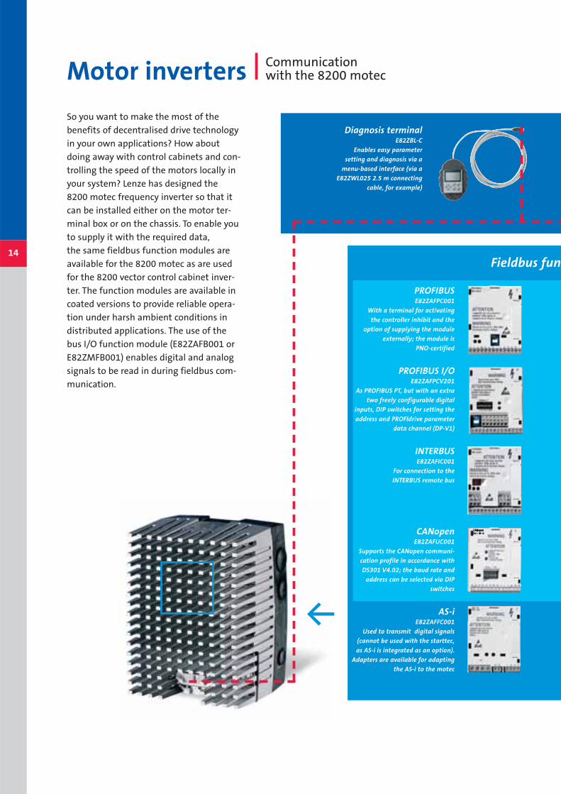
So you want to make the most of the
benefits of decentralised drive technology
in your own applications? How about
doing away with control cabinets and con-
trolling the speed of the motors locally in
your system? Lenze has designed the
8200 motec frequency inverter so that it
can be installed either on the motor ter-
minal box or on the chassis. To enable you
to supply it with the required data,
the same fieldbus function modules are
available for the 8200 motec as are used
for the 8200 vector control cabinet inver-
ter. The function modules are available in
coated versions to provide reliable opera-
tion under harsh ambient conditions in
distributed applications. The use of the
bus I/O function module (E82ZAFB001 or
E82ZMFB001) enables digital and analog
signals to be read in during fieldbus com-
munication.
Motor inverters Communication with the 8200 motec
Z
Fieldbus fun
Diagnosis terminalE82ZBL-C
Enables easy parameter
setting and diagnosis via a
menu-based interface (via a
E82ZWL025 2.5 m connecting
cable, for example)
PROFIBUS I/OE82ZAFPCV201
As PROFIBUS PT, but with an extra
two freely configurable digital
inputs, DIP switches for setting the
address and PROFIdrive parameter
data channel (DP-V1)
CAN I/OE82ZAFCC201
In addition to the terminal for
activating the controller inhibit,
two more freely configurable
digital input terminals can be used.
DIP switches define the addresses
and baud rates (the module cannot
be used with the starttec).
CAN E82ZAFCC001
Lenze system bus for data
exchange between nodes
without a master control
LECOM B E82ZAFLC001
RS485 – suitable for universal
use with the open Lenze
LECOM A/B protocol for PC and
PLC interfacing
DeviceNetE82ZAFVC001
ODVA-certified module;
baud rate and address can be
selected via DIP switches
15
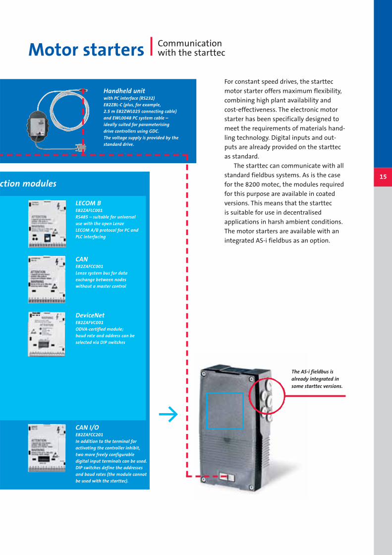
For constant speed drives, the starttec
motor starter offers maximum flexibility,
combining high plant availability and
cost-effectiveness. The electronic motor
starter has been specifically designed to
meet the requirements of materials hand-
ling technology. Digital inputs and out-
puts are already provided on the starttec
as standard.
The starttec can communicate with all
standard fieldbus systems. As is the case
for the 8200 motec, the modules required
for this purpose are available in coated
versions. This means that the starttec
is suitable for use in decentralised
applications in harsh ambient conditions.
The motor starters are available with an
integrated AS-i fieldbus as an option.
Motor starters Communication with the starttec
The AS-i fieldbus isalready integrated insome starttec versions.
Y
ction modules
Handheld unitwith PC interface (RS232)
E82ZBL-C (plus, for example,
2.5 m E82ZWL025 connecting cable)
and EWL0048 PC system cable –
ideally suited for parameterising
drive controllers using GDC.
The voltage supply is provided by the
standard drive.
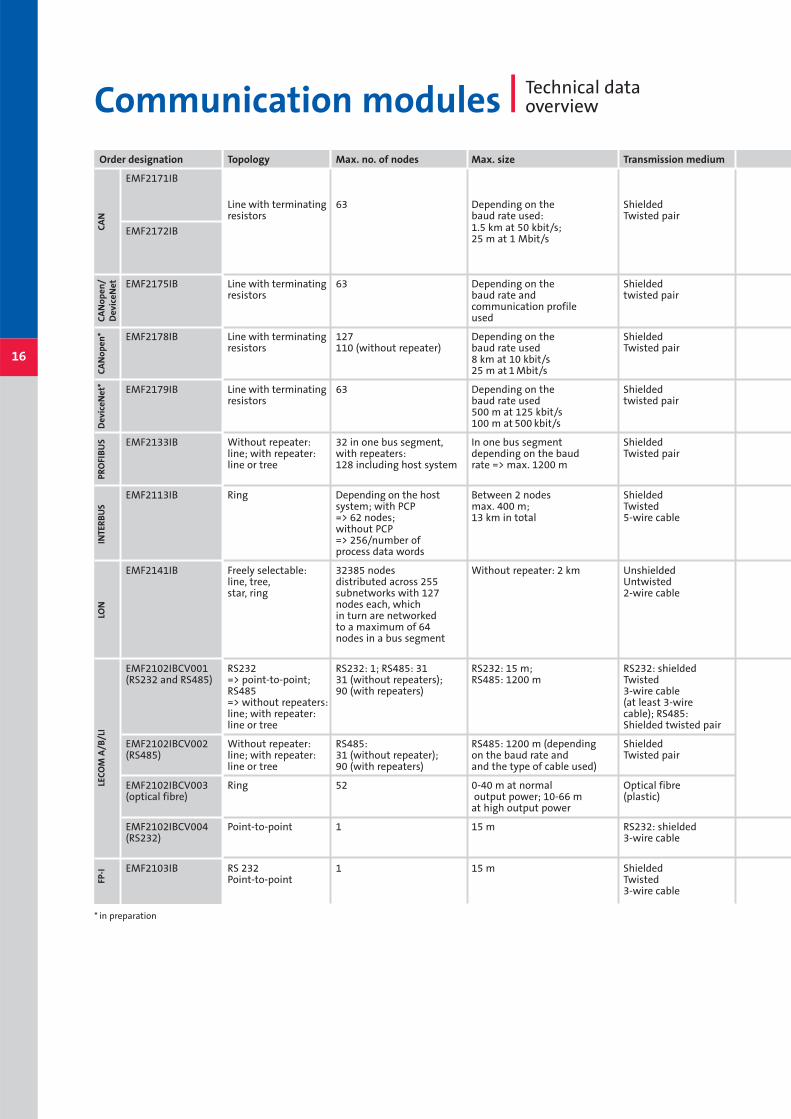
Order designation Topology Max. no. of nodes Max. size Transmission medium
EMF2171IB
Line with terminating 63 Depending on the Shieldedresistors baud rate used: Twisted pair
EMF2172IB 1.5 km at 50 kbit/s;25 m at 1 Mbit/s
EMF2175IB Line with terminating 63 Depending on the Shieldedresistors baud rate and twisted pair
communication profileused
EMF2178IB Line with terminating 127 Depending on the Shieldedresistors 110 (without repeater) baud rate used Twisted pair
8 km at 10 kbit/s25 m at 1 Mbit/s
EMF2179IB Line with terminating 63 Depending on the Shieldedresistors baud rate used twisted pair
500 m at 125 kbit/s100 m at 500 kbit/s
EMF2133IB Without repeater: 32 in one bus segment, In one bus segment Shieldedline; with repeater: with repeaters: depending on the baud Twisted pairline or tree 128 including host system rate => max. 1200 m
EMF2113IB Ring Depending on the host Between 2 nodes Shielded system; with PCP max. 400 m; Twisted=> 62 nodes; 13 km in total 5-wire cablewithout PCP => 256/number of process data words
EMF2141IB Freely selectable: 32385 nodes Without repeater: 2 km Unshieldedline, tree, distributed across 255 Untwistedstar, ring subnetworks with 127 2-wire cable
nodes each, whichin turn are networkedto a maximum of 64nodes in a bus segment
EMF2102IBCV001 RS232 RS232: 1; RS485: 31 RS232: 15 m; RS232: shielded(RS232 and RS485) => point-to-point; 31 (without repeaters); RS485: 1200 m Twisted
RS485 90 (with repeaters) 3-wire cable => without repeaters: (at least 3-wireline; with repeater: cable); RS485:line or tree Shielded twisted pair
EMF2102IBCV002 Without repeater: RS485: RS485: 1200 m (depending Shielded (RS485) line; with repeater: 31 (without repeater); on the baud rate and Twisted pair
line or tree 90 (with repeaters) and the type of cable used)
EMF2102IBCV003 Ring 52 0-40 m at normal Optical fibre (optical fibre) output power; 10-66 m (plastic)
at high output power
EMF2102IBCV004 Point-to-point 1 15 m RS232: shielded(RS232) 3-wire cable
EMF2103IB RS 232 1 15 m ShieldedPoint-to-point Twisted
3-wire cable
16
Communication modules Technical dataoverview
CA
Nop
en/
Dev
iceN
etC
AN
open
*D
evic
eNet
*FP
-ILE
COM
A/B
/LI
LON
INTE
RB
US
PRO
FIB
US
CA
N
* in preparation
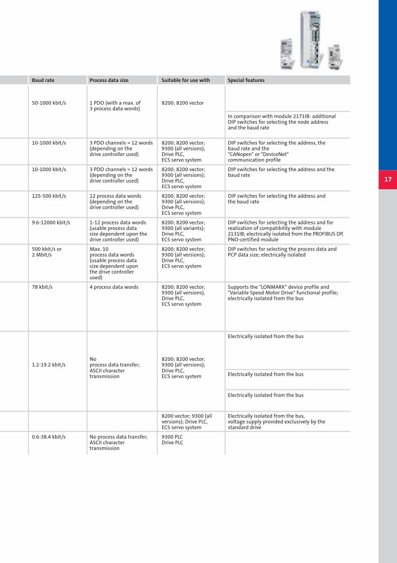
Baud rate Process data size Suitable for use with Special features
50-1000 kbit/s 1 PDO (with a max. of 8200; 8200 vector3 process data words)
In comparison with module 2171IB: additional DIP switches for selecting the node addressand the baud rate
10-1000 kbit/s 3 PDO channels = 12 words 8200; 8200 vector; DIP switches for selecting the address, the(depending on the 9300 (all versions); baud rate and the drive controller used) Drive PLC, "CANopen" or "DeviceNet"
ECS servo system communication profile
10-1000 kbit/s 3 PDO channels = 12 words 8200; 8200 vector; DIP switches for selecting the address and the (depending on the 9300 (all versions); baud ratedrive controller used) Drive PLC,
ECS servo system
125-500 kbit/s 12 process data words 8200; 8200 vector; DIP switches for selecting the address and(depending on the 9300 (all versions); the baud ratedrive controller used) Drive PLC,
ECS servo system
9.6-12000 kbit/s 1-12 process data words 8200; 8200 vector; DIP switches for selecting the address and for(usable process data 9300 (all variants); realisation of compatibility with modulesize dependent upon the Drive PLC, 2131IB; electrically isolated from the PROFIBUS DP,drive controller used) ECS servo system PNO-certified module
500 kbit/s or Max. 10 8200; 8200 vector; DIP switches for selecting the process data and2 Mbit/s process data words 9300 (all versions); PCP data size; electrically isolated
(usable process data Drive PLC,size dependent upon ECS servo systemthe drive controllerused)
78 kbit/s 4 process data words 8200; 8200 vector; Supports the "LONMARK" device profile and9300 (all versions), "Variable Speed Motor Drive" functional profile;Drive PLC, electrically isolated from the busECS servo system
Electrically isolated from the bus
No 8200; 8200 vector; 1.2-19.2 kbit/s process data transfer; 9300 (all versions);
ASCII character Drive PLC,Electrically isolated from the bustransmission ECS servo system
Electrically isolated from the bus
8200 vector; 9300 (all Electrically isolated from the bus,versions); Drive PLC, voltage supply provided exclusively by theECS servo system standard drive
0.6-38.4 kbit/s No process data transfer; 9300 PLCASCII character Drive PLCtransmission
17

Order designation Topology Max. no. of nodes Max. size Transmission medium
E82ZAFCC
E82ZAFCC001Depending on the baud rate used:
E82ZAFCC010 3.9 km at 20 kbit/s;80 m at 500 kbit/s
E82ZAFCC100 Line with terminating 63 Depending on the Shielded resistors baud rate used: Twisted pair
3.9 km at 20 kbit/s;9 m at 1 Mbit/s
E82ZAFCC200
E82ZAFCC201 Depending on the baud rate used:
E82ZAFCC210 3.9 km at 20 kbit/s;80 m at 500 kbit/s
E82ZAFUC001 Line with terminating 127 Depending on the Shieldedresistors 106 (without repeater) baud rate used: Twisted pair
8 km at 10 kbit/s;9 m at 1 Mbit/s
E82ZAFUC010
E82ZAFVC001 Line with terminating 63 100 m Shieldedresistors Twisted pair
E82ZAFVC010 100 m at 500 kbit/s;500 m at 125 kbit/s
E82ZAFPC
E82ZAFPC001 Without repeater: 32 in one bus segment, In one bus segment Shieldedline; with repeater: with repeaters: 125 depending on the Twisted pair
E82ZAFPC010 line or tree including host system and baud rate
repeaters => max. 1200 m
E82ZAFPC201
E82ZAFICRing Depending on the host Between 2 nodes Shielded
E82ZAFIC001system: with PCP max. 400 m; Twisted pair=> 62 nodes; 13 km in total 3x2-wire cable
E82ZAFIC010
without PCP =>256/numberof process data words
E82ZAFLC
E82ZAFLC001 Without repeater: 31 in one bus segment; 1200 m (depending on the Shieldedline; with repeater: with repeaters: 90 baud rate and Twisted pair
E82ZAFLC010 line or tree type of cable used)
E82ZAFFC
E82ZAFFC001 Tree 31 100 m Unshielded
E82ZAFFC010 Untwisted 2-wire cable
18
Fieldbus function modules Technical dataoverview
Note: The technical data for the standard I/O, application I/O and the bus I/O can be found in the relevant catalogues (e.g. 8200 vector and 8200 motec).
AS-
iLE
COM
BIN
TER
BU
SPR
OFI
BU
SD
evic
eNet
CA
Nop
enSy
stem
bu
s
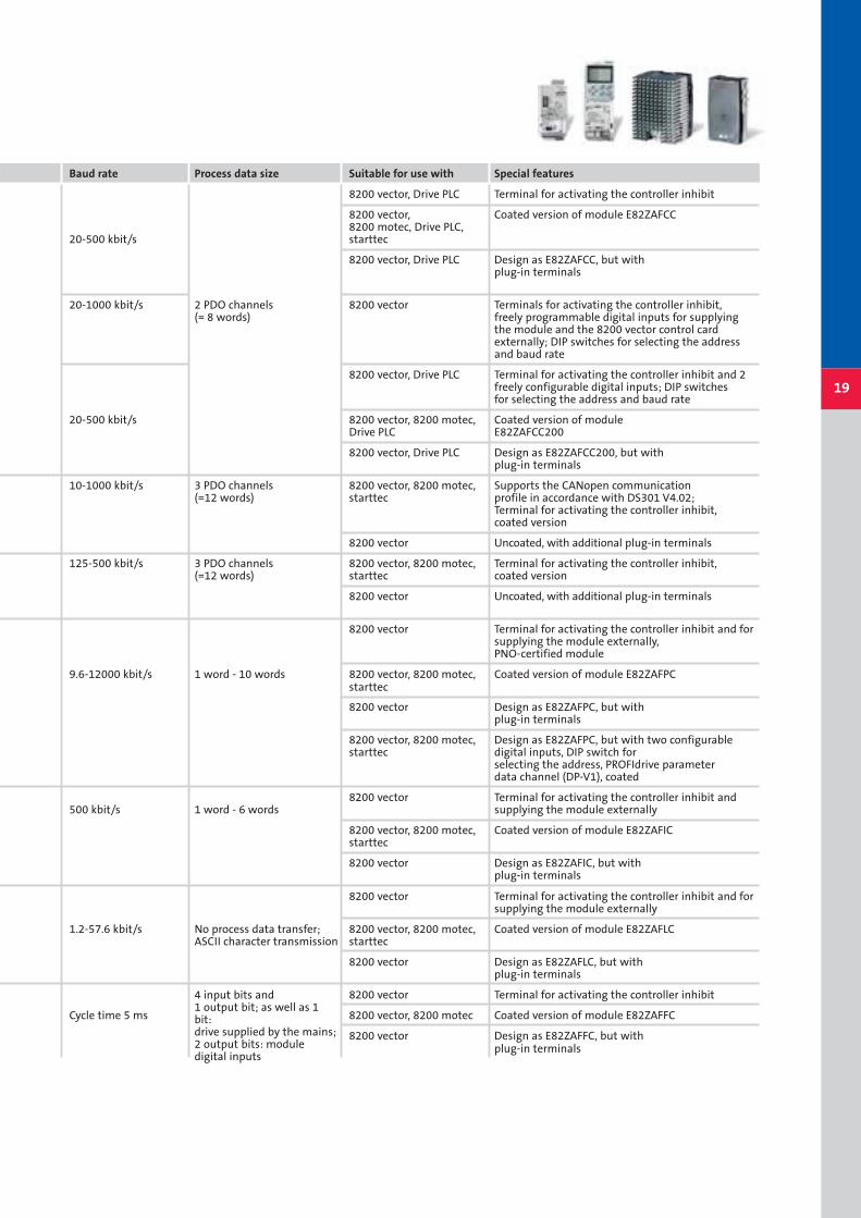
Baud rate Process data size Suitable for use with Special features
8200 vector, Drive PLC Terminal for activating the controller inhibit
8200 vector, Coated version of module E82ZAFCC8200 motec, Drive PLC,
20-500 kbit/s starttec
8200 vector, Drive PLC Design as E82ZAFCC, but with plug-in terminals
20-1000 kbit/s 2 PDO channels 8200 vector Terminals for activating the controller inhibit, (= 8 words) freely programmable digital inputs for supplying
the module and the 8200 vector control cardexternally; DIP switches for selecting the addressand baud rate
8200 vector, Drive PLC Terminal for activating the controller inhibit and 2freely configurable digital inputs; DIP switches for selecting the address and baud rate
20-500 kbit/s 8200 vector, 8200 motec, Coated version of module Drive PLC E82ZAFCC200
8200 vector, Drive PLC Design as E82ZAFCC200, but with plug-in terminals
10-1000 kbit/s 3 PDO channels 8200 vector, 8200 motec, Supports the CANopen communication(=12 words) starttec profile in accordance with DS301 V4.02;
Terminal for activating the controller inhibit,coated version
8200 vector Uncoated, with additional plug-in terminals
125-500 kbit/s 3 PDO channels 8200 vector, 8200 motec, Terminal for activating the controller inhibit,(=12 words) starttec coated version
8200 vector Uncoated, with additional plug-in terminals
8200 vector Terminal for activating the controller inhibit and for supplying the module externally,PNO-certified module
9.6-12000 kbit/s 1 word - 10 words 8200 vector, 8200 motec, Coated version of module E82ZAFPCstarttec
8200 vector Design as E82ZAFPC, but withplug-in terminals
8200 vector, 8200 motec, Design as E82ZAFPC, but with two configurablestarttec digital inputs, DIP switch for
selecting the address, PROFIdrive parameterdata channel (DP-V1), coated
8200 vector Terminal for activating the controller inhibit and500 kbit/s 1 word - 6 words supplying the module externally
8200 vector, 8200 motec, Coated version of module E82ZAFICstarttec
8200 vector Design as E82ZAFIC, but with plug-in terminals
8200 vector Terminal for activating the controller inhibit and forsupplying the module externally
1.2-57.6 kbit/s No process data transfer; 8200 vector, 8200 motec, Coated version of module E82ZAFLCASCII character transmission starttec
8200 vector Design as E82ZAFLC, but withplug-in terminals
8200 vector Terminal for activating the controller inhibit
Cycle time 5 ms 8200 vector, 8200 motec Coated version of module E82ZAFFC
8200 vector Design as E82ZAFFC, but withplug-in terminals
19
4 input bits and1 output bit; as well as 1bit:drive supplied by the mains;2 output bits: module digital inputs
Len
ze D
rive
Sys
tem
s G
mb
H ·
Post
fach
10
1352
· D-3
1763
Ham
eln
· Tec
hn
ical
alt
erat
ion
s re
serv
ed ·
Prin
ted
in G
erm
any
11.2
005
en·5
4 3
2 1
13054397
“Our customers come first. Customer satisfaction is what motivates us.
By thinking in terms of how we can add value for our customers we can
increase productivity through reliability.”
“We will provide you with exactly what you need – perfectly co-ordinated
products and solutions with the right functions for your machines and
installations. That is what we mean by ‘quality’.”
“Take advantage of our wealth of expertise. For more than 50 years
we have been gathering experience in various fields and implementing
it consistently and rigorously in our products, motion functions and
preprepared solutions for industry.”
“We identify with your targets and strive towards a long-term partner-
ship which benefits both sides. Our competent support and consultation
process means that we can provide you with tailor-made solutions.
We are there for you and can offer assistance in all of the key processes.”
You can rely on our service. Expert advice is available 24 hours a day,
365 days a year, in more than 30 countries via our international
helpline: 008000 24 Hours (008000 2446877).
“The world is our marketplace. We develop and manufacture
internationally. Wherever you are in the world, we are nearby.”
www.Lenze.com
It’s good to know why we are there for you


