8/6/2010
1
COMPACTION INNOVATIONS
AND CONTROL BASED ON
SOIL MODULUS
By
Jean-Louis BRIAUD
President of ISSMGE
Professor, Texas A&M University, USA
J-L Briaud, Texas A&M University
ACKNOWLEDGEMENTS
Hans Kloubert, BOMAG
Roland Anderegg, AMMANN
Carl Petterson, GEODYNAMIK
Dermot Kelly, LANDPAC
Derek Avalle, BROONS
Kukjo Kim, Texas A&M Univ.
Jeongbok Seo, Texas A&M Univ.
J-L Briaud, Texas A&M University
8/6/2010
2
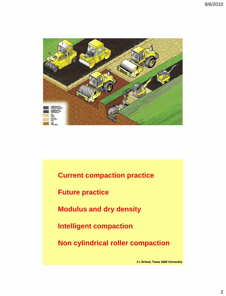
Current compaction practice
Future practice
Modulus and dry density
Intelligent compaction
Non cylindrical roller compaction
J-L Briaud, Texas A&M University
8/6/2010
3
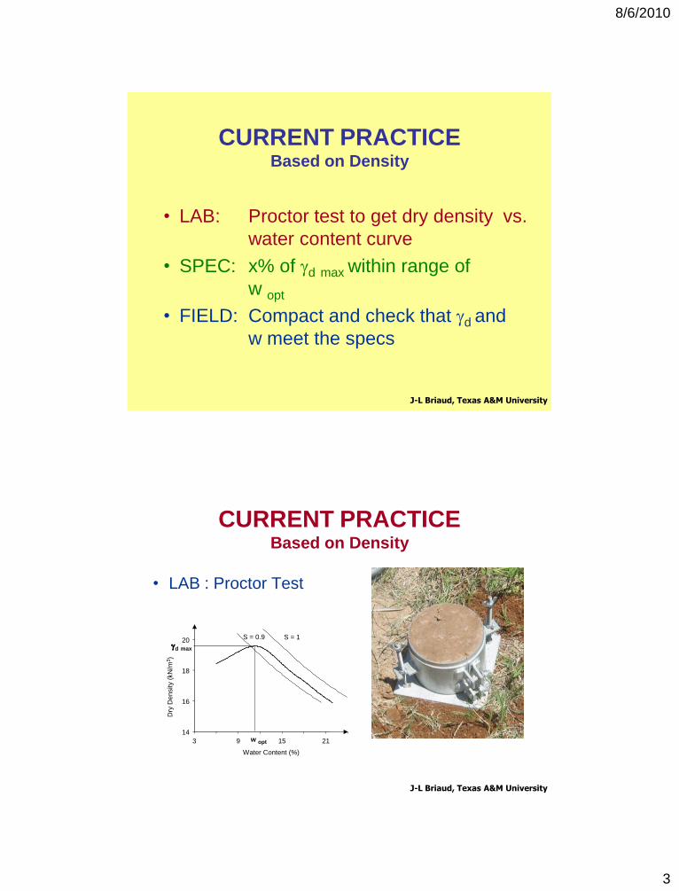
CURRENT PRACTICEBased on Density
• LAB: Proctor test to get dry density vs.
water content curve
• SPEC: x% of gd max within range of
w opt
• FIELD: Compact and check that gd and
w meet the specs
J-L Briaud, Texas A&M University
• LAB : Proctor Test
J-L Briaud, Texas A&M University
CURRENT PRACTICEBased on Density
Water Content (%)
3 9 15 21
14
16
18
20
Dry
Density (
kN
/m3)
gd max
w opt
S = 1S = 0.9
Water Content (%)
3 9 15 21
14
16
18
20
Dry
Density (
kN
/m3)
gd max
w opt
S = 1S = 0.9
8/6/2010
4
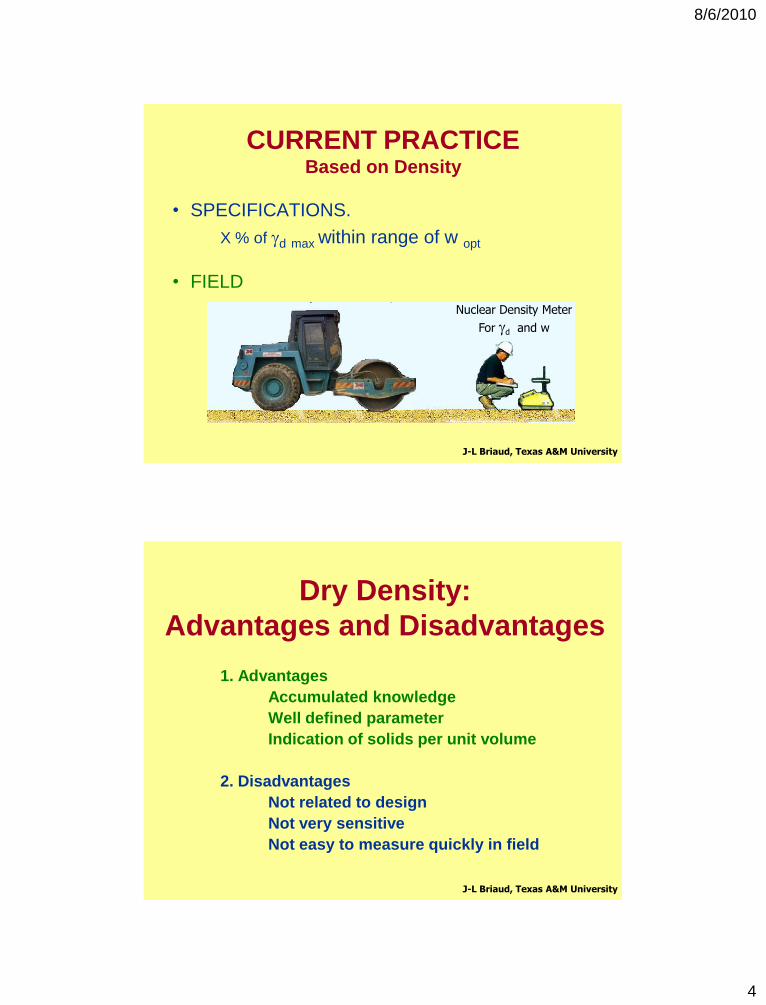
• SPECIFICATIONS.
X % of gd max within range of w opt
• FIELD
J-L Briaud, Texas A&M University
Nuclear Density Meter
For gd and w
CURRENT PRACTICEBased on Density
Dry Density:
Advantages and Disadvantages
1. Advantages
Accumulated knowledge
Well defined parameter
Indication of solids per unit volume
2. Disadvantages
Not related to design
Not very sensitive
Not easy to measure quickly in field
J-L Briaud, Texas A&M University
8/6/2010
5
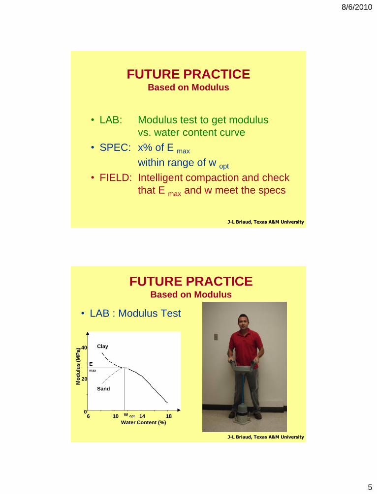
FUTURE PRACTICEBased on Modulus
• LAB: Modulus test to get modulus
vs. water content curve
• SPEC: x% of E max
within range of w opt
• FIELD: Intelligent compaction and check
that E max and w meet the specs
J-L Briaud, Texas A&M University
FUTURE PRACTICEBased on Modulus
• LAB : Modulus Test
J-L Briaud, Texas A&M University
Water Content (%)
6 10 14 18
Mo
du
lus
(M
Pa)
0
20
40
Sand
Clay
E max
w opt
8/6/2010
6
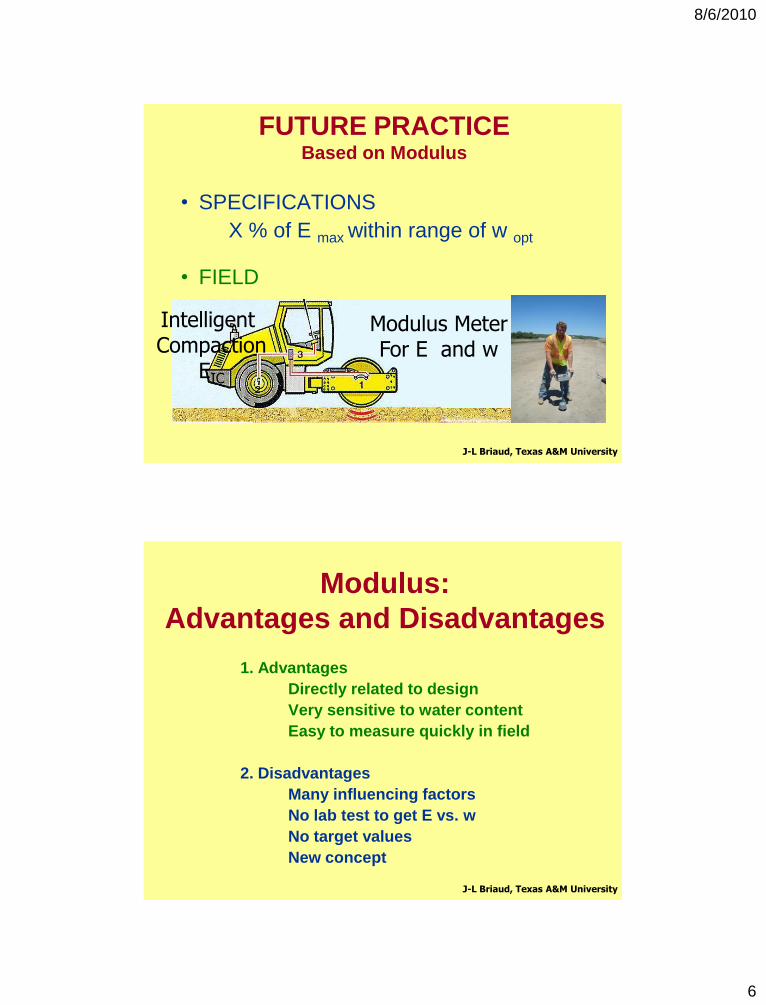
• SPECIFICATIONS
X % of E max within range of w opt
• FIELD
J-L Briaud, Texas A&M University
Modulus MeterFor E and w
Intelligent Compaction
EIC
FUTURE PRACTICEBased on Modulus
Modulus:
Advantages and Disadvantages
1. Advantages
Directly related to design
Very sensitive to water content
Easy to measure quickly in field
2. Disadvantages
Many influencing factors
No lab test to get E vs. w
No target values
New concept
J-L Briaud, Texas A&M University
8/6/2010
7
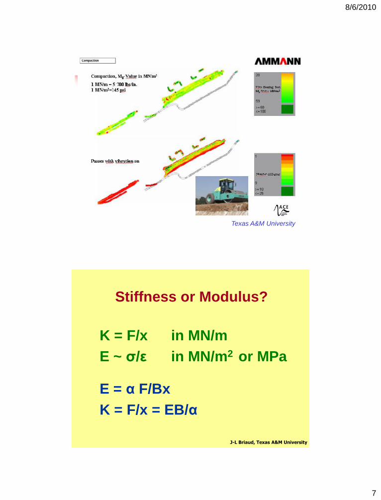
Texas A&M University
Stiffness or Modulus?
K = F/x in MN/m
E ~ σ/ε in MN/m2 or MPa
E = α F/Bx
K = F/x = EB/α
J-L Briaud, Texas A&M University
8/6/2010
8
Stiffness or Modulus?
Stiffness depends on the size of the roller.
Modulus does not; it is a property of the soil only.
Use the modulus, not the stiffness
J-L Briaud, Texas A&M University
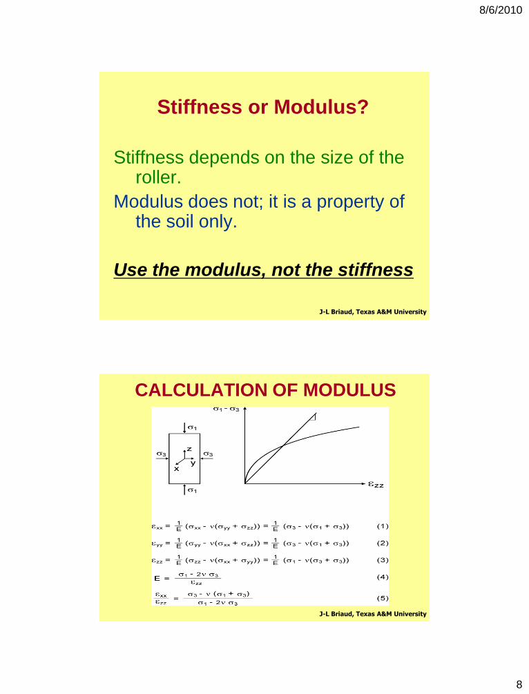
CALCULATION OF MODULUS
J-L Briaud, Texas A&M University
8/6/2010
9
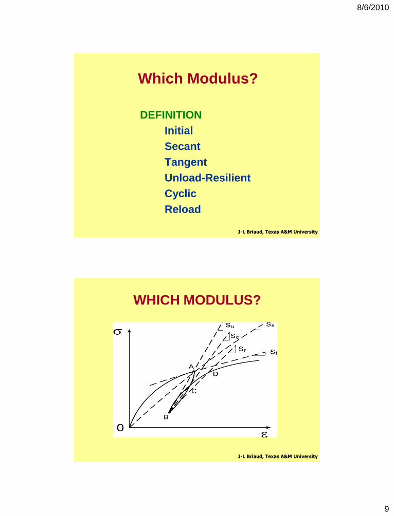
Which Modulus?
DEFINITION
Initial
Secant
Tangent
Unload-Resilient
Cyclic
Reload
J-L Briaud, Texas A&M University
WHICH MODULUS?
J-L Briaud, Texas A&M University
8/6/2010
10
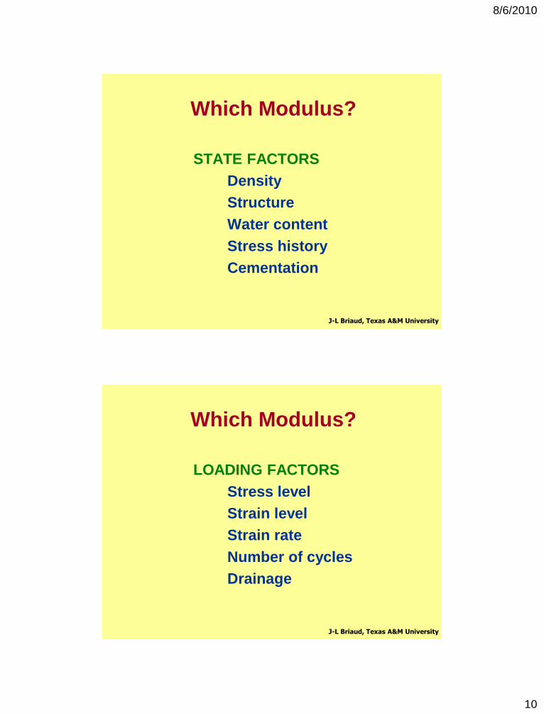
Which Modulus?
STATE FACTORS
Density
Structure
Water content
Stress history
Cementation
J-L Briaud, Texas A&M University
Which Modulus?
LOADING FACTORS
Stress level
Strain level
Strain rate
Number of cycles
Drainage
J-L Briaud, Texas A&M University
8/6/2010
11
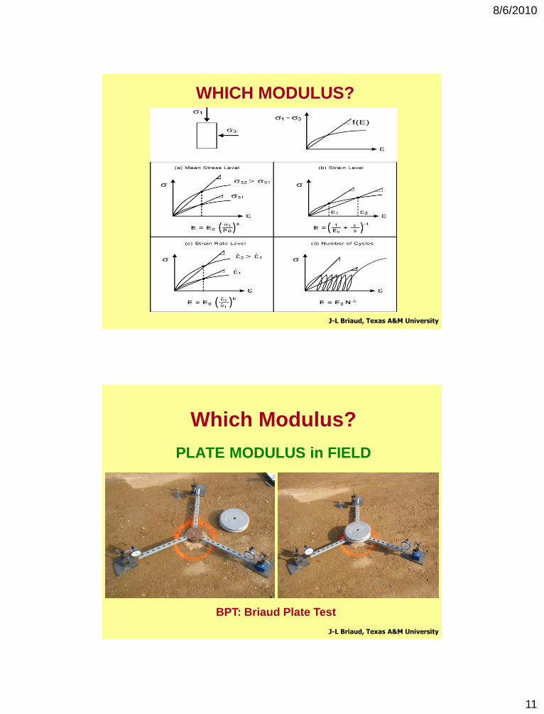
WHICH MODULUS?
J-L Briaud, Texas A&M University
Which Modulus?
PLATE MODULUS in FIELD
J-L Briaud, Texas A&M University
BPT: Briaud Plate Test
8/6/2010
12
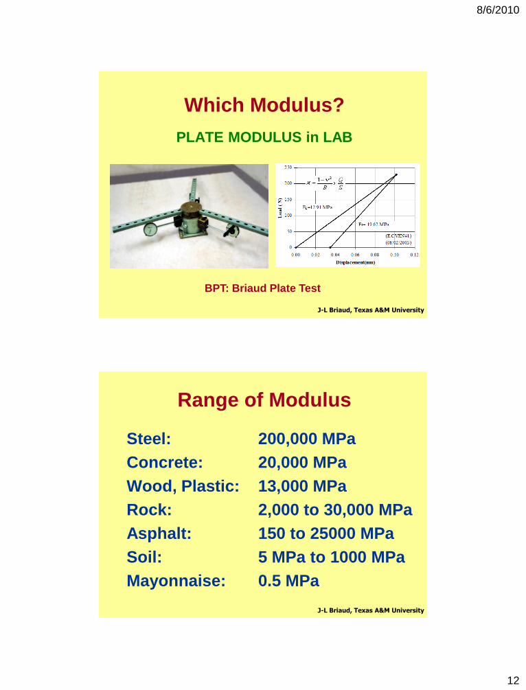
Which Modulus?
PLATE MODULUS in LAB
J-L Briaud, Texas A&M University
BPT: Briaud Plate Test
Range of Modulus
Steel: 200,000 MPa
Concrete: 20,000 MPa
Wood, Plastic: 13,000 MPa
Rock: 2,000 to 30,000 MPa
Asphalt: 150 to 25000 MPa
Soil: 5 MPa to 1000 MPa
Mayonnaise: 0.5 MPa
J-L Briaud, Texas A&M University
8/6/2010
13
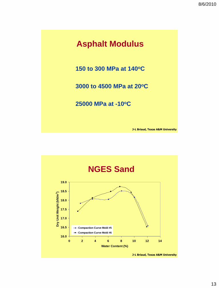
Asphalt Modulus
150 to 300 MPa at 140oC
3000 to 4500 MPa at 20oC
25000 MPa at -10oC
J-L Briaud, Texas A&M University
NGES Sand
16.0
16.5
17.0
17.5
18.0
18.5
19.0
0 2 4 6 8 10 12 14
Water Content (%)
Dry
Un
it W
eig
ht
(kN
/m3)
Compaction Curve Mold #5
Compaction Curve Mold #6
J-L Briaud, Texas A&M University
8/6/2010
14
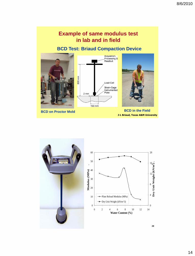
Example of same modulus test
in lab and in field
J-L Briaud, Texas A&M University
BCD Test: Briaud Compaction Device
BCD on Proctor Mold BCD in the Field
0
10
20
30
40
50
60
0 2 4 6 8 10 12 14
Water Content (%)
Mo
du
lus (
MP
a)
.
0
4
8
12
16
20D
ry
Un
it W
eig
ht
(kN
/m3)
.
Plate Reload Modulus (MPa)
Dry Unit Weight (kN/m^3)
28
8/6/2010
15
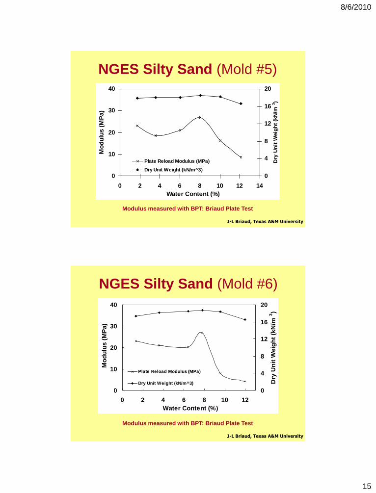
NGES Silty Sand (Mold #5)
0
10
20
30
40
0 2 4 6 8 10 12 14
Water Content (%)
Mo
du
lus (
MP
a)
0
4
8
12
16
20
Dry
Un
it W
eig
ht
(kN
/m3)
Plate Reload Modulus (MPa)
Dry Unit Weight (kN/m^3)
J-L Briaud, Texas A&M University
Modulus measured with BPT: Briaud Plate Test
NGES Silty Sand (Mold #6)
0
10
20
30
40
0 2 4 6 8 10 12
Water Content (%)
Mo
du
lus (
MP
a)
0
4
8
12
16
20
Dry
Un
it W
eig
ht
(kN
/m3)
Plate Reload Modulus (MPa)
Dry Unit Weight (kN/m^3)
J-L Briaud, Texas A&M University
Modulus measured with BPT: Briaud Plate Test
8/6/2010
16
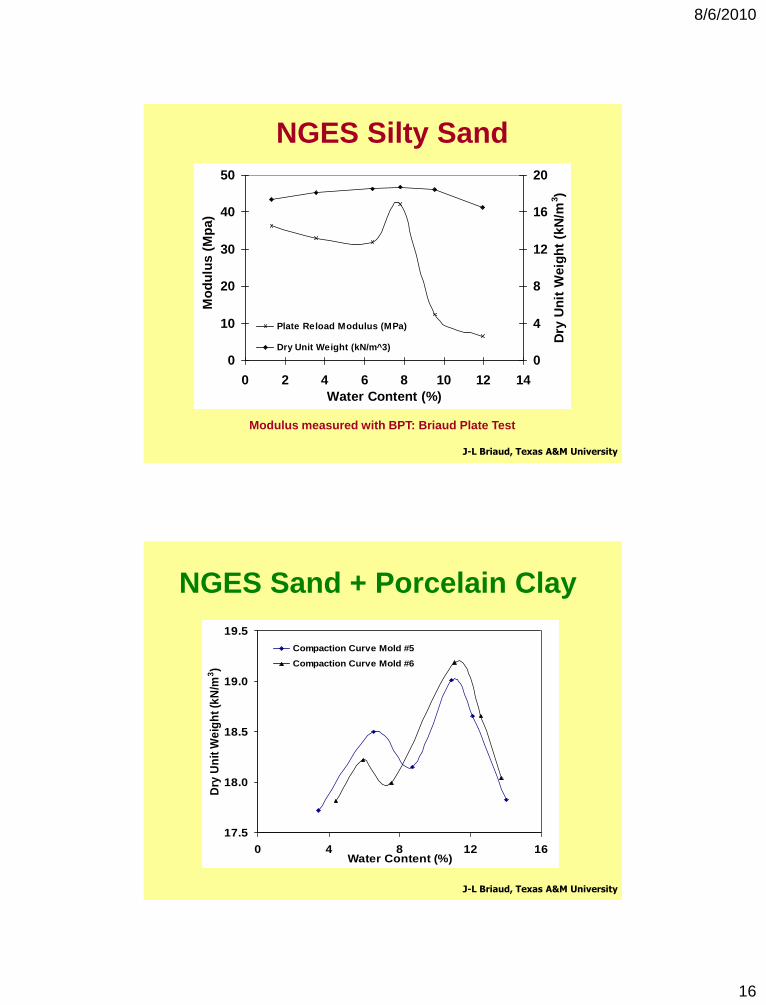
NGES Silty Sand
0
10
20
30
40
50
0 2 4 6 8 10 12 14
Water Content (%)
Mo
du
lus (
Mp
a)
0
4
8
12
16
20
Dry
Un
it W
eig
ht
(kN
/m3)
Plate Reload Modulus (MPa)
Dry Unit Weight (kN/m^3)
J-L Briaud, Texas A&M University
Modulus measured with BPT: Briaud Plate Test
17.5
18.0
18.5
19.0
19.5
0 4 8 12 16Water Content (%)
Dry
Un
it W
eig
ht
(kN
/m3)
Compaction Curve Mold #5
Compaction Curve Mold #6
NGES Sand + Porcelain Clay
J-L Briaud, Texas A&M University
8/6/2010
17
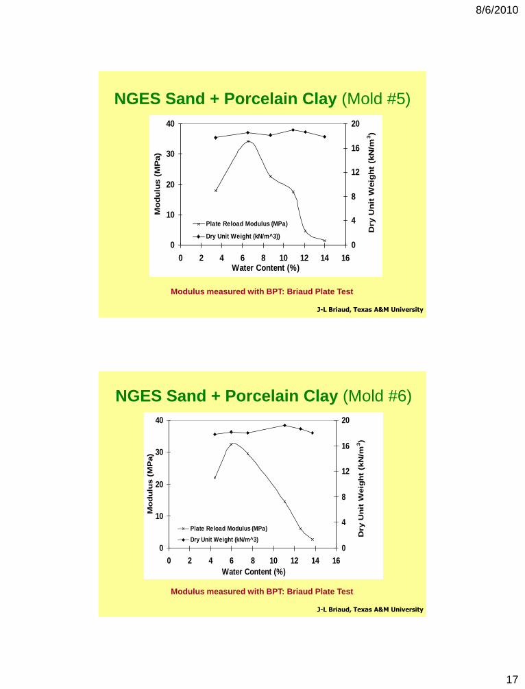
NGES Sand + Porcelain Clay (Mold #5)
0
10
20
30
40
0 2 4 6 8 10 12 14 16Water Content (%)
Mo
du
lus (
MP
a)
0
4
8
12
16
20
Dry U
nit
Weig
ht
(kN
/m3)
Plate Reload Modulus (MPa)
Dry Unit Weight (kN/m^3))
J-L Briaud, Texas A&M University
Modulus measured with BPT: Briaud Plate Test
NGES Sand + Porcelain Clay (Mold #6)
0
10
20
30
40
0 2 4 6 8 10 12 14 16
Water Content (%)
Mo
du
lus (
MP
a)
0
4
8
12
16
20
Dry U
nit
Weig
ht
(kN
/m3)
Plate Reload Modulus (MPa)
Dry Unit Weight (kN/m^3)
J-L Briaud, Texas A&M University
Modulus measured with BPT: Briaud Plate Test
8/6/2010
18
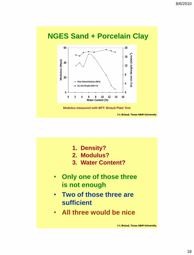
NGES Sand + Porcelain Clay
J-L Briaud, Texas A&M University
Modulus measured with BPT: Briaud Plate Test
0
20
40
60
0 2 4 6 8 10 12 14 16Water Content (%)
Mo
du
lus (
Mp
a)
0
4
8
12
16
20
Dry U
nit
Weig
ht
(kN
/m3)
Plate Reload Modulus (MPa)
Dry Unit Weight (kN/m^3)
0
20
40
60
0 2 4 6 8 10 12 14 16Water Content (%)
Mo
du
lus (
Mp
a)
0
4
8
12
16
20
Dry U
nit
Weig
ht
(kN
/m3)
Plate Reload Modulus (MPa)
Dry Unit Weight (kN/m^3)
• Only one of those three
is not enough
• Two of those three are
sufficient
• All three would be nice
J-L Briaud, Texas A&M University
1. Density?
2. Modulus?
3. Water Content?
8/6/2010
19
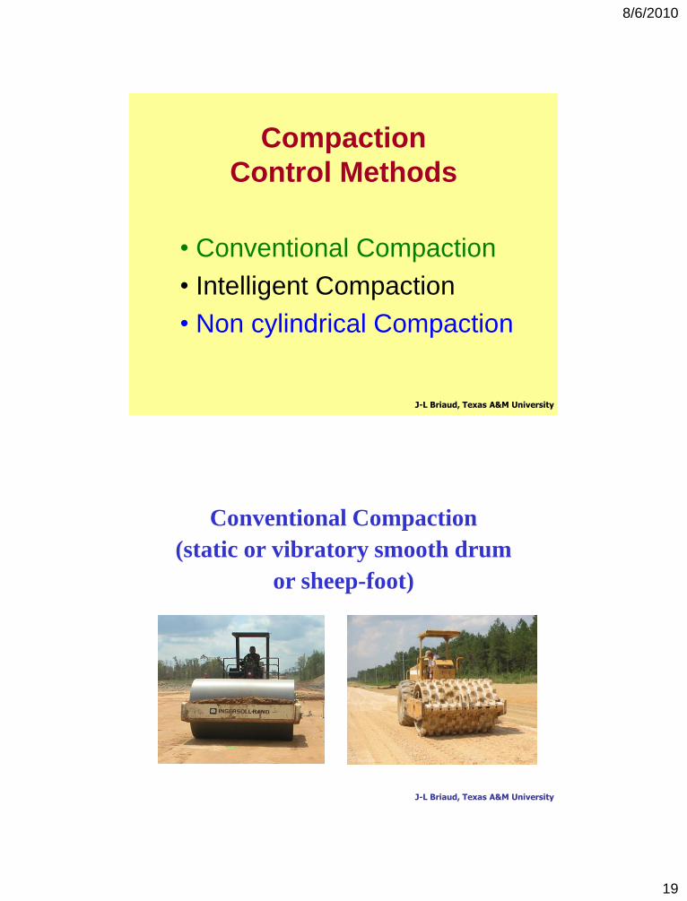
Compaction
Control Methods
• Conventional Compaction
• Intelligent Compaction
• Non cylindrical Compaction
J-L Briaud, Texas A&M University
Conventional Compaction
(static or vibratory smooth drum
or sheep-foot)
J-L Briaud, Texas A&M University
8/6/2010
20
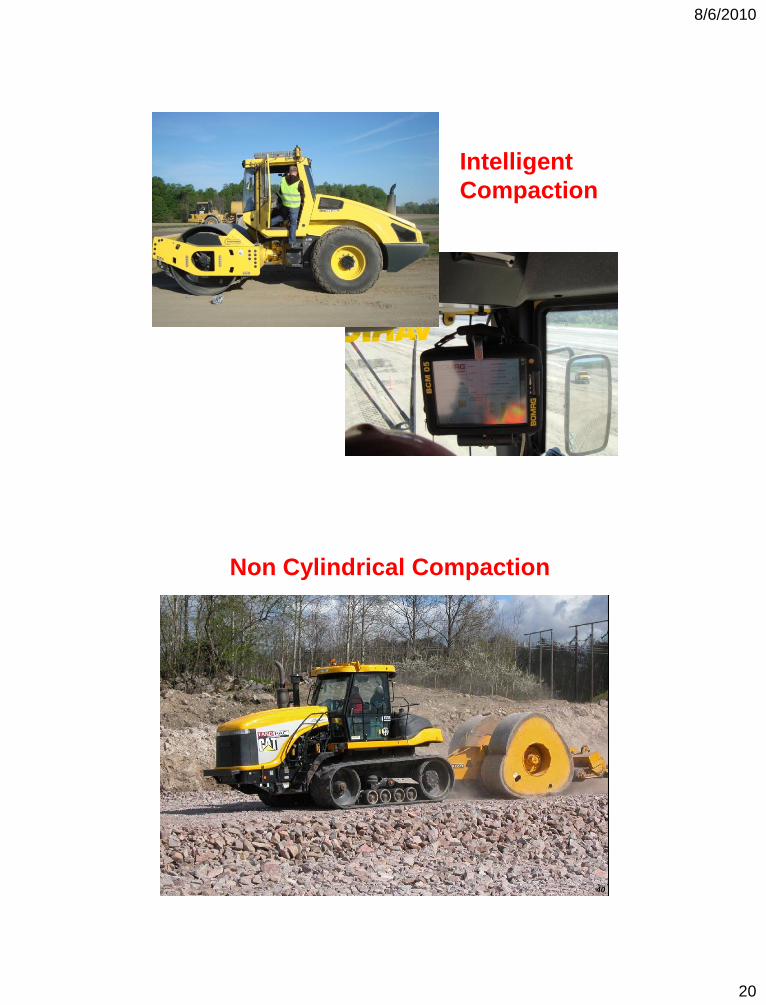
Intelligent
Compaction
40
Non Cylindrical Compaction
8/6/2010
21
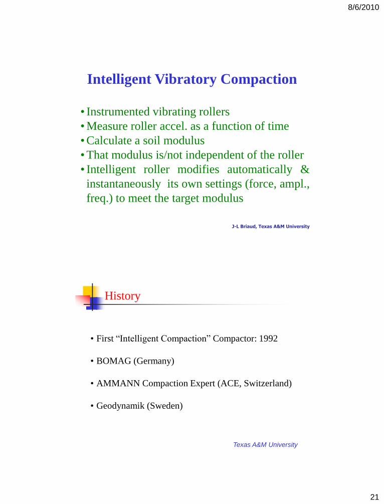
Intelligent Vibratory Compaction
• Instrumented vibrating rollers
• Measure roller accel. as a function of time
• Calculate a soil modulus
• That modulus is/not independent of the roller
• Intelligent roller modifies automatically &
instantaneously its own settings (force, ampl.,
freq.) to meet the target modulus
J-L Briaud, Texas A&M University
Texas A&M University
History
• First “Intelligent Compaction” Compactor: 1992
• BOMAG (Germany)
• AMMANN Compaction Expert (ACE, Switzerland)
• Geodynamik (Sweden)
8/6/2010
22
Slide 43
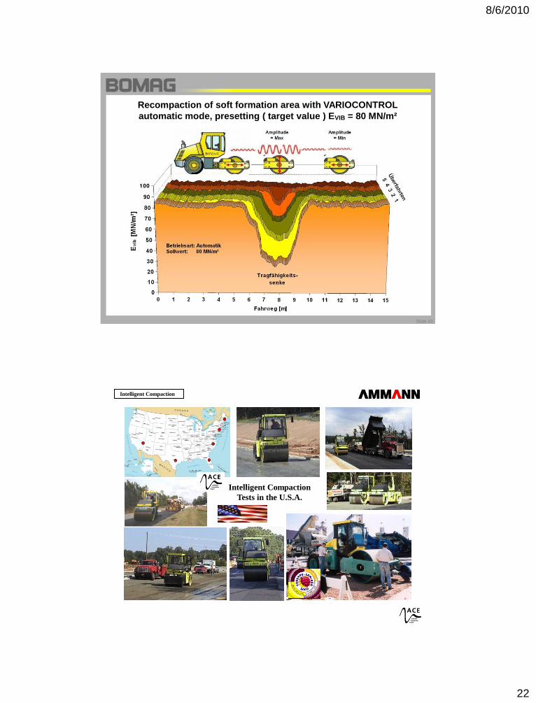
Recompaction of soft formation area with VARIOCONTROL
automatic mode, presetting ( target value ) EVIB = 80 MN/m²
Intelligent Compaction
Intelligent Compaction
Tests in the U.S.A.
8/6/2010
23
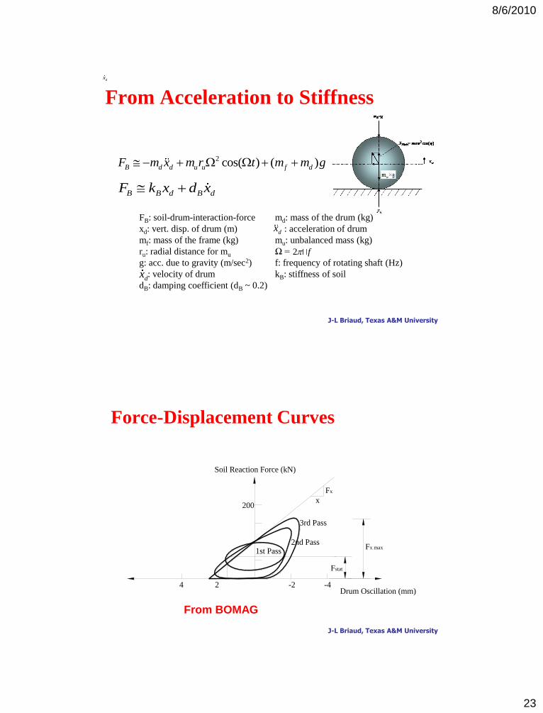
From Acceleration to Stiffness
2 cos( ) ( )B d d u u f dF m x m r t m m g
B B d B dF k x d x
FB: soil-drum-interaction-force md: mass of the drum (kg)
xd: vert. disp. of drum (m) : acceleration of drum
mf: mass of the frame (kg) mu: unbalanced mass (kg)
ru: radial distance for mu Ω =
g: acc. due to gravity (m/sec2) f: frequency of rotating shaft (Hz)
: velocity of drum kB: stiffness of soil
dB: damping coefficient (dB ~ 0.2)
dx
dx
2 f
dx
J-L Briaud, Texas A&M University
4 2 -2
200
Soil Reaction Force (kN)
Fx max
-4
Fstat
x
Fx
1st Pass2nd Pass
3rd Pass
Drum Oscillation (mm)
Force-Displacement Curves
J-L Briaud, Texas A&M University
From BOMAG
8/6/2010
24
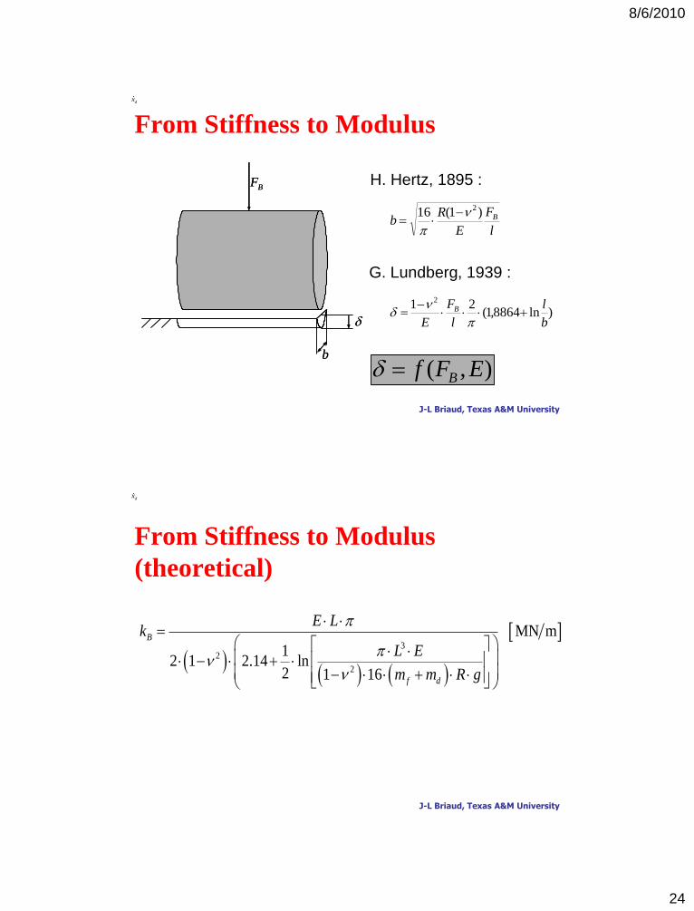
From Stiffness to Modulusdx
b
BF
b
BF
),( EFf B
l
F
E
Rb B)1(16 2
H. Hertz, 1895 :
)ln8864,1(21 2
b
l
l
F
E
B
G. Lundberg, 1939 :
J-L Briaud, Texas A&M University
From Stiffness to Modulus
(theoretical)
dx
3
2
2
MN m
12 1 2.14 ln
2 1 16
B
f d
E Lk
L E
m m R g
J-L Briaud, Texas A&M University
8/6/2010
25
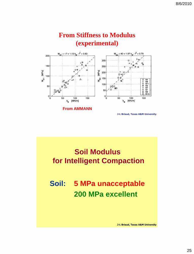
From Stiffness to Modulus
(experimental)
J-L Briaud, Texas A&M University
From AMMANN
Soil Modulus
for Intelligent Compaction
Soil: 5 MPa unacceptable
200 MPa excellent
J-L Briaud, Texas A&M University
8/6/2010
26
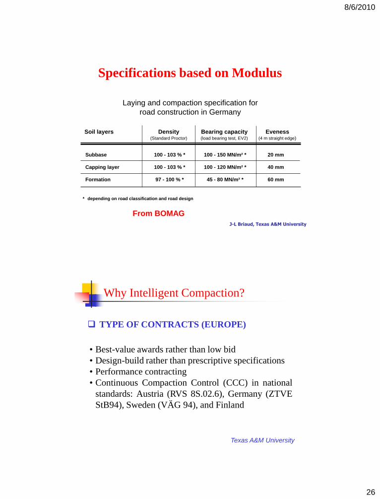
Soil layers Density Bearing capacity Eveness(Standard Proctor) (load bearing test, EV2) (4 m straight edge)
Laying and compaction specification for
road construction in Germany
Subbase 100 - 103 % * 100 - 150 MN/m² * 20 mm
Capping layer 100 - 103 % * 100 - 120 MN/m² * 40 mm
Formation 97 - 100 % * 45 - 80 MN/m² * 60 mm
* depending on road classification and road design
Specifications based on Modulus
J-L Briaud, Texas A&M University
From BOMAG
Texas A&M University
Why Intelligent Compaction?
TYPE OF CONTRACTS (EUROPE)
• Best-value awards rather than low bid
• Design-build rather than prescriptive specifications
• Performance contracting
• Continuous Compaction Control (CCC) in national
standards: Austria (RVS 8S.02.6), Germany (ZTVE
StB94), Sweden (VÄG 94), and Finland
8/6/2010
27
Texas A&M University
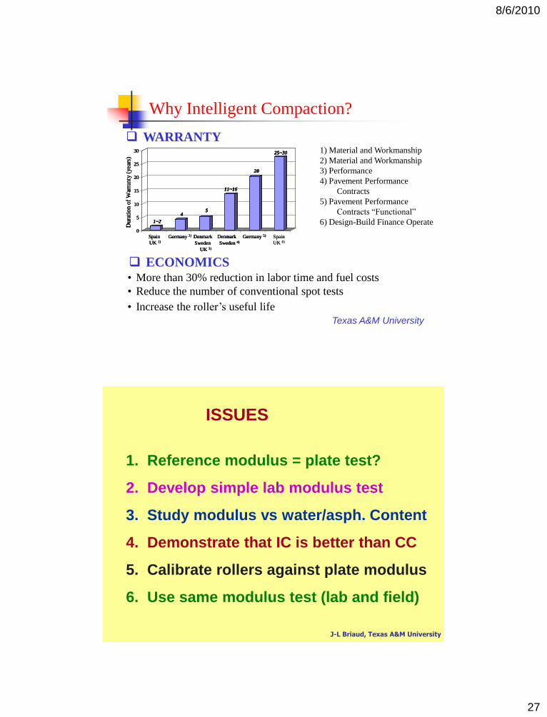
Why Intelligent Compaction?
WARRANTY
Spain
UK 6)
0
5
10
15
20
25
30
Spain
UK 1)
Germany 2) Denmark
Sweden
UK 3)
Denmark
Sweden 4)
Germany 5)
Dura
tion o
f W
arra
nty
(year
s)
1~2
45
11~16
20
25~30
Spain
UK 6)
0
5
10
15
20
25
30
Spain
UK 1)
Germany 2) Denmark
Sweden
UK 3)
Denmark
Sweden 4)
Germany 5)
Dura
tion o
f W
arra
nty
(year
s)
1~2
45
11~16
20
25~30
0
5
10
15
20
25
30
Spain
UK 1)
Germany 2) Denmark
Sweden
UK 3)
Denmark
Sweden 4)
Germany 5)
Dura
tion o
f W
arra
nty
(year
s)
1~2
45
11~16
20
25~30 1) Material and Workmanship
2) Material and Workmanship
3) Performance
4) Pavement Performance
Contracts
5) Pavement Performance
Contracts “Functional”
6) Design-Build Finance Operate
ECONOMICS• More than 30% reduction in labor time and fuel costs
• Reduce the number of conventional spot tests
• Increase the roller’s useful life
1. Reference modulus = plate test?
2. Develop simple lab modulus test
3. Study modulus vs water/asph. Content
4. Demonstrate that IC is better than CC
5. Calibrate rollers against plate modulus
6. Use same modulus test (lab and field)
ISSUES
J-L Briaud, Texas A&M University
8/6/2010
28
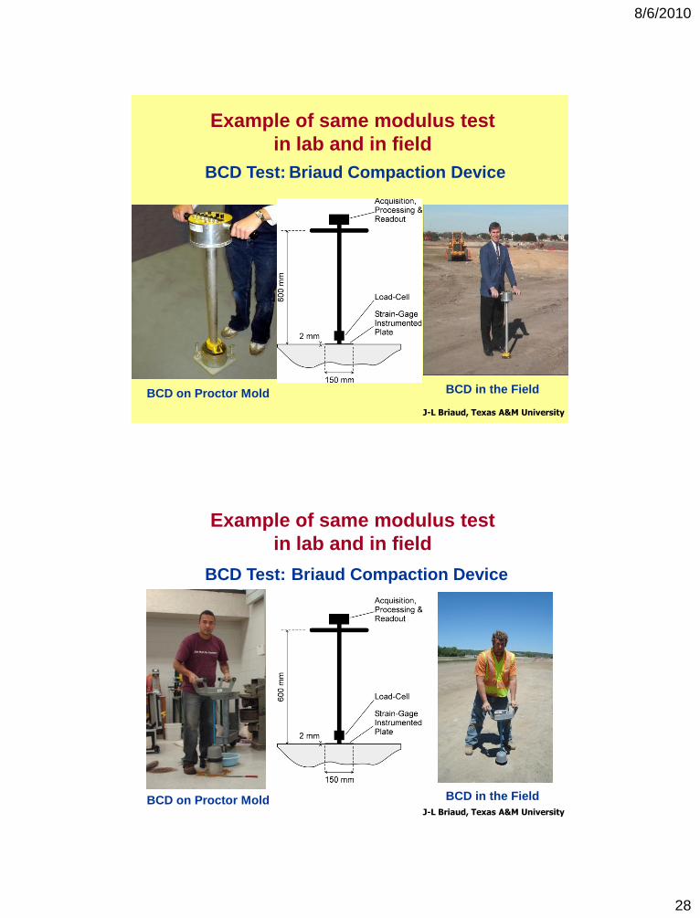
Example of same modulus test
in lab and in field
J-L Briaud, Texas A&M University
BCD Test: Briaud Compaction Device
BCD on Proctor Mold BCD in the Field
Example of same modulus test
in lab and in field
J-L Briaud, Texas A&M University
BCD Test: Briaud Compaction Device
BCD on Proctor Mold BCD in the Field
8/6/2010
29
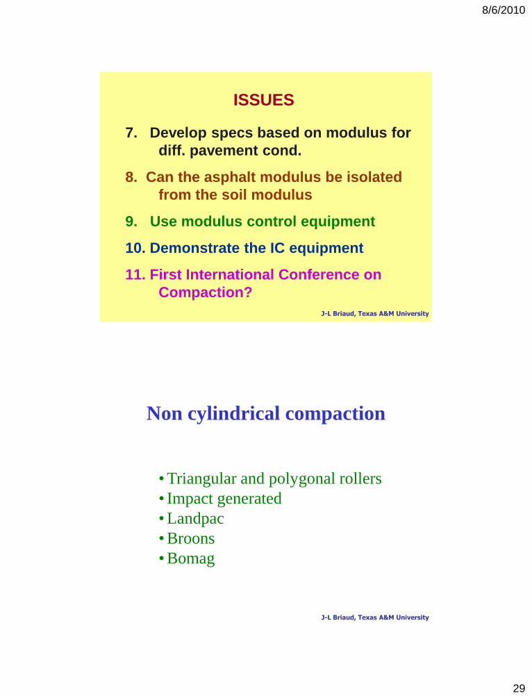
7. Develop specs based on modulus for
diff. pavement cond.
8. Can the asphalt modulus be isolated
from the soil modulus
9. Use modulus control equipment
10. Demonstrate the IC equipment
11. First International Conference on
Compaction?
ISSUES
J-L Briaud, Texas A&M University
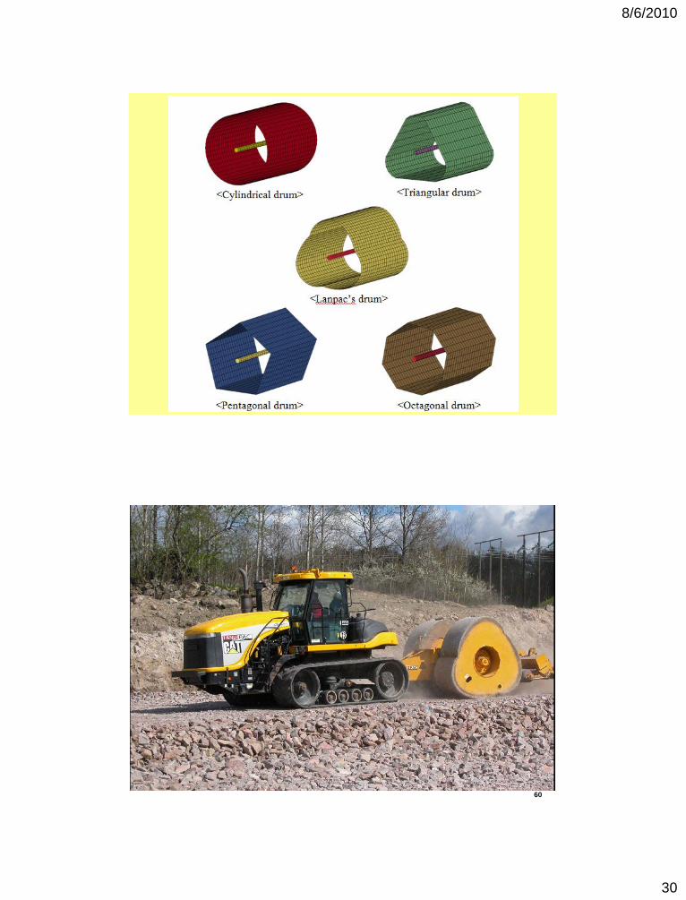
Non cylindrical compaction
• Triangular and polygonal rollers
• Impact generated
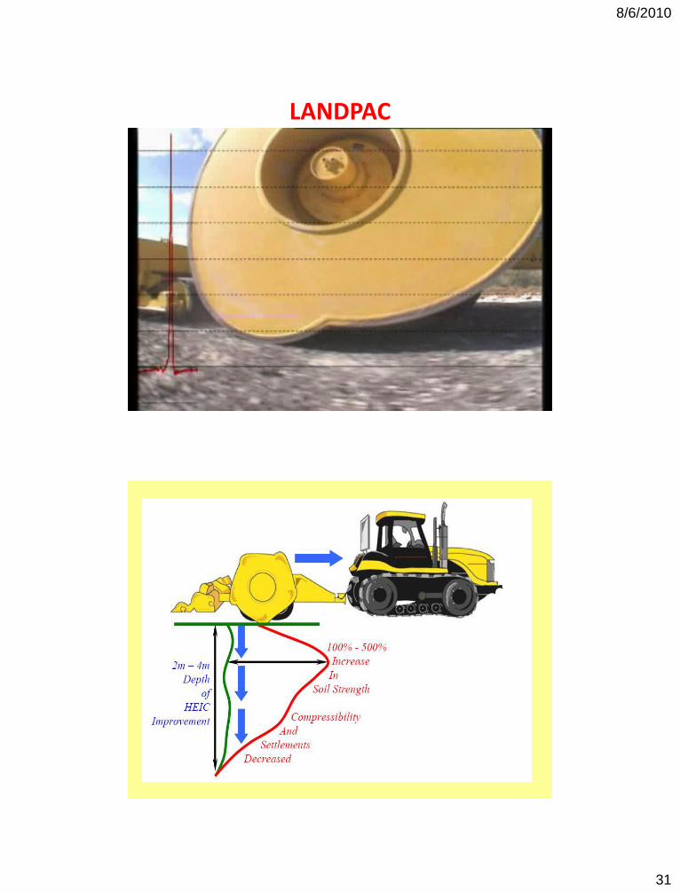
• Landpac
• Broons
• Bomag
J-L Briaud, Texas A&M University
8/6/2010
30
60
8/6/2010
31
LANDPAC
8/6/2010
32
8/6/2010
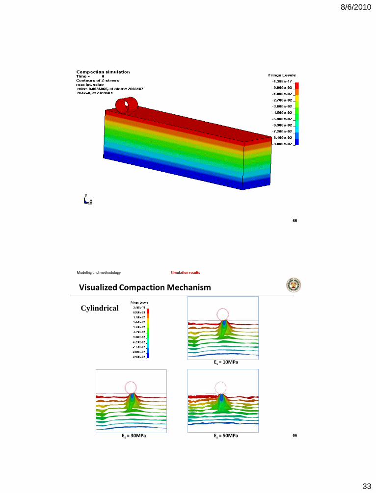
33
65
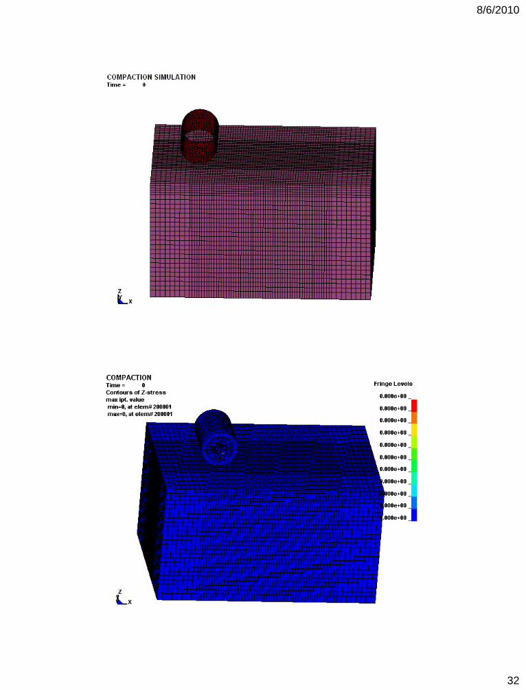
Modeling and methodology Simulation results
Cylindrical
Visualized Compaction Mechanism
Es = 10MPa
Es = 30MPa Es = 50MPa 66
8/6/2010
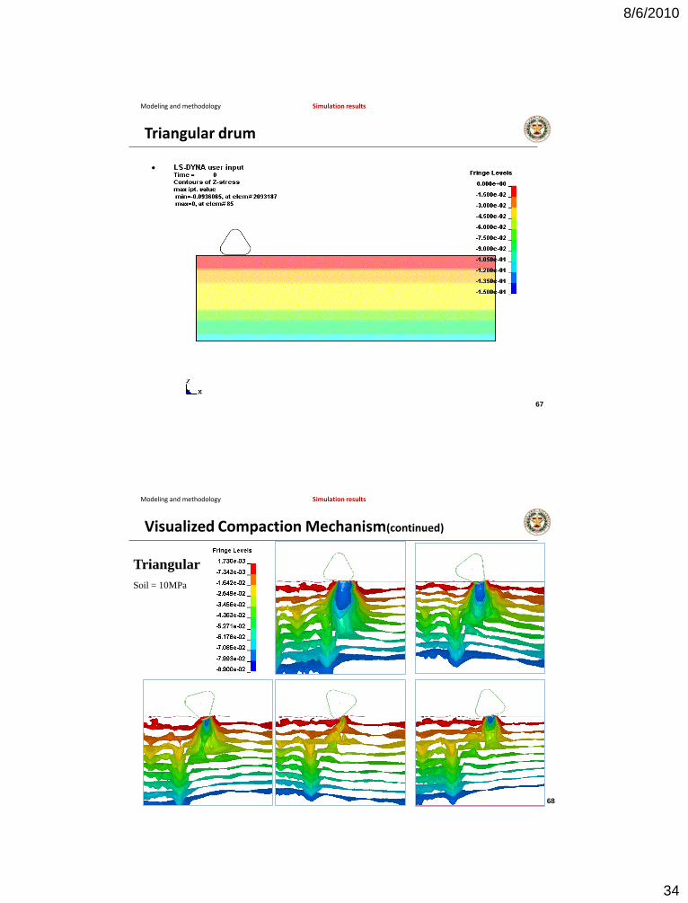
34
Triangular drum
• Simulation results
Modeling and methodology Simulation results
67
Modeling and methodology Simulation results
Triangular
Soil = 10MPa
Visualized Compaction Mechanism(continued)
68
8/6/2010
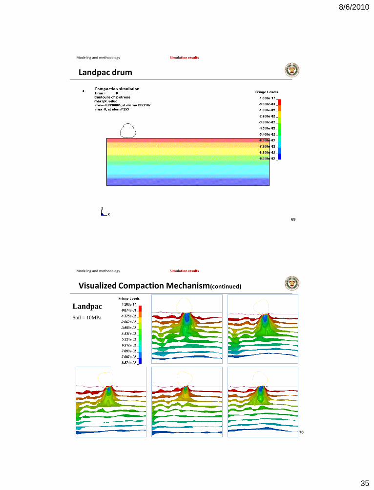
35
Landpac drum
• Simulation results
Modeling and methodology Simulation results
69
Visualized Compaction Mechanism(continued)
Modeling and methodology Simulation results
Landpac
Soil = 10MPa
70
8/6/2010
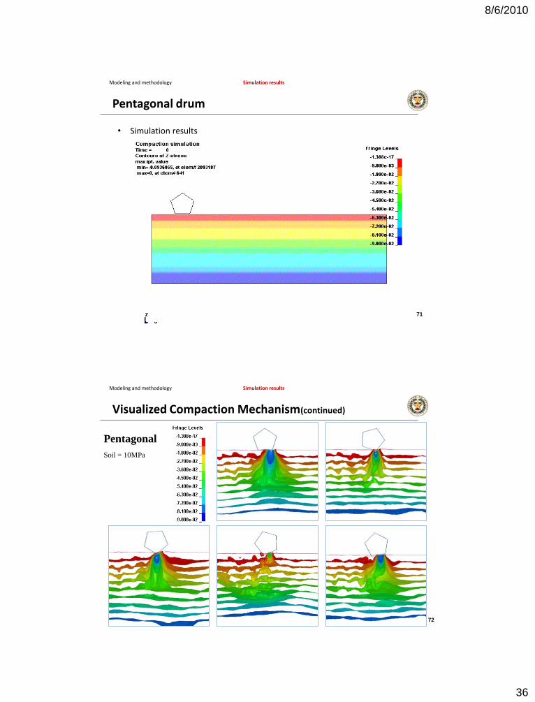
36
Pentagonal drum
• Simulation results
Modeling and methodology Simulation results
71
Modeling and methodology Simulation results
Pentagonal
Soil = 10MPa
Visualized Compaction Mechanism(continued)
72
8/6/2010
37
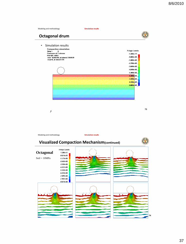
Octagonal drum
• Simulation results
Modeling and methodology Simulation results
73
Modeling and methodology Simulation results
Octagonal
Soil = 10MPa
Visualized Compaction Mechanism(continued)
74
8/6/2010
38
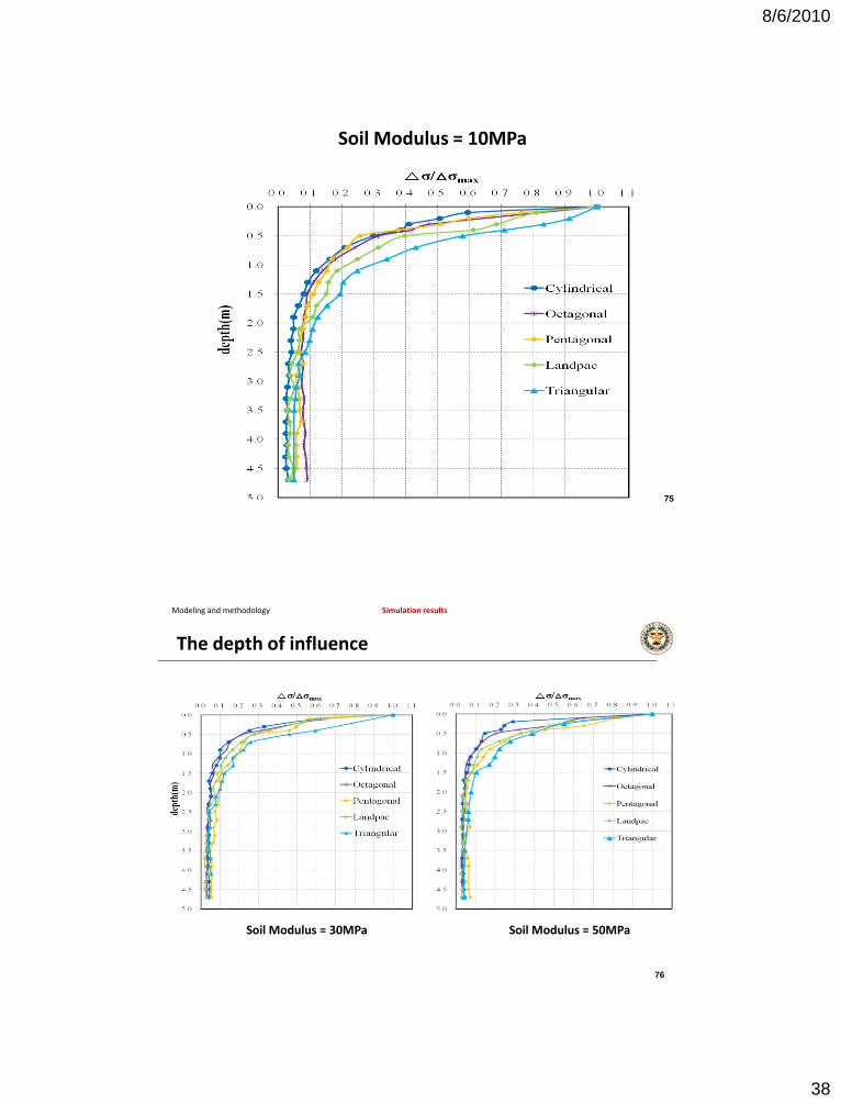
Soil Modulus = 10MPa
75
The depth of influence
Modeling and methodology Simulation results
Soil Modulus = 50MPaSoil Modulus = 30MPa
76
8/6/2010
39
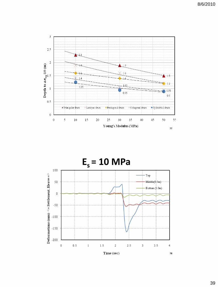
77
Es = 10 MPa
78
8/6/2010
40
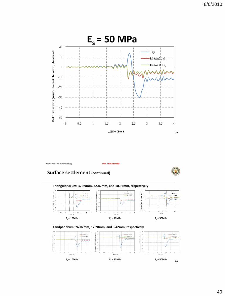
Es = 50 MPa
79
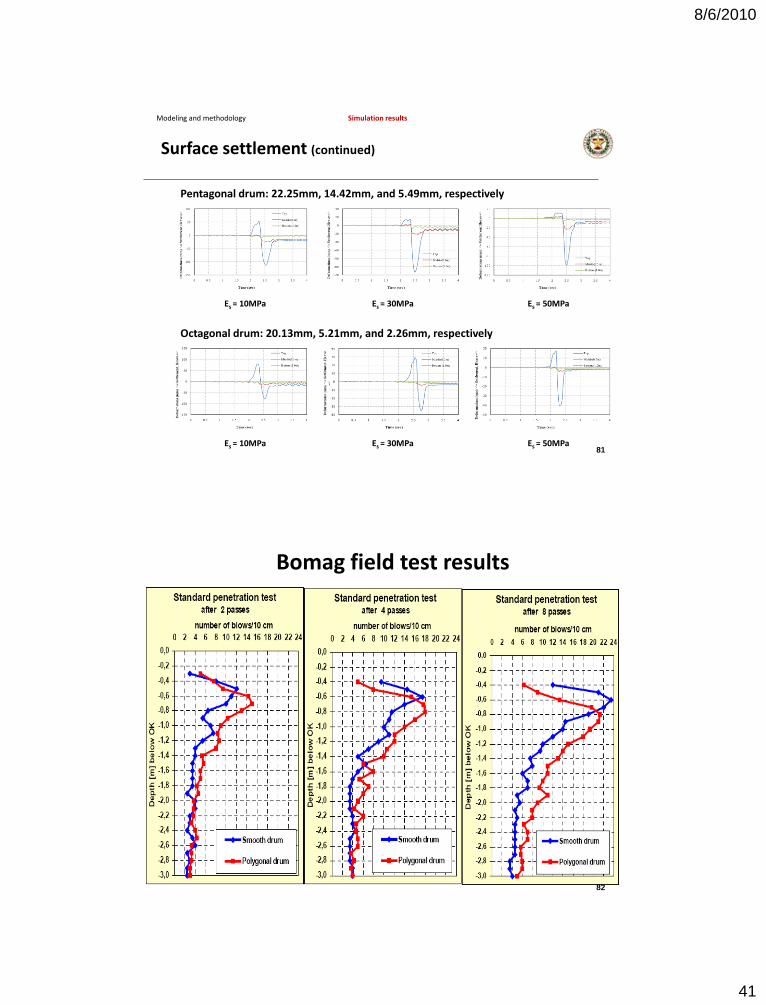
Modeling and methodology Simulation results
Surface settlement (continued)
Es = 10MPa Es = 30MPa Es = 50MPa
Triangular drum: 32.89mm, 22.82mm, and 10.92mm, respectively
Es = 10MPa Es = 30MPa Es = 50MPa
Landpac drum: 26.02mm, 17.28mm, and 8.42mm, respectively
80
8/6/2010
41
Modeling and methodology Simulation results
Surface settlement (continued)
Es = 10MPa Es = 30MPa Es = 50MPa
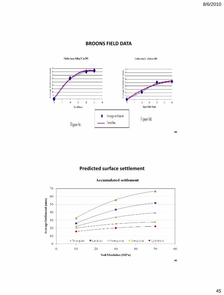
Pentagonal drum: 22.25mm, 14.42mm, and 5.49mm, respectively
Es = 10MPa Es = 30MPa Es = 50MPa
Octagonal drum: 20.13mm, 5.21mm, and 2.26mm, respectively
81
Bomag field test results
82
8/6/2010
42
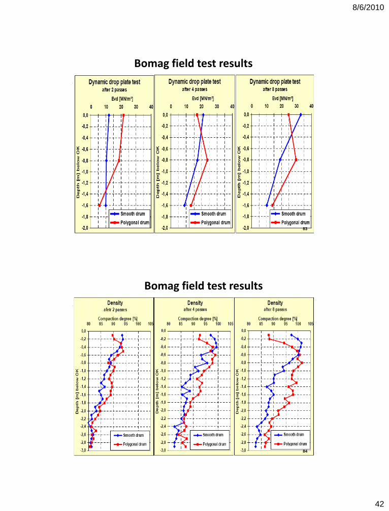
Bomag field test results
83
Bomag field test results
84
8/6/2010
43
85
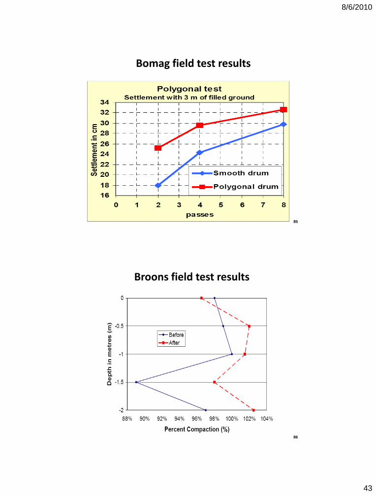
Bomag field test results
Broons field test results
86
8/6/2010
44
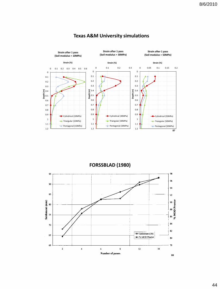
Texas A&M University simulations
0
0.1
0.2
0.3
0.4
0.5
0.6
0.7
0.8
0.9
1
1.1
1.2
0 0.1 0.2 0.3 0.4 0.5 0.6
Dep
th (
m)
Strain (%)
Strain after 1 pass(Soil modulus = 10MPa)
Cylindrical (10MPa)
Triangular (10MPa)
Pentagonal (10MPa)
0
0.1
0.2
0.3
0.4
0.5
0.6
0.7
0.8
0.9
1
1.1
1.2
0 0.1 0.2 0.3
Dep
th (
m)
Strain (%)
Strain after 1 pass(Soil modulus = 30MPa)
Cylindrical (30MPa)
Triangular (30MPa)
Pentagonal (30MPa)
0
0.1
0.2
0.3
0.4
0.5
0.6
0.7
0.8
0.9
1
1.1
1.2
0 0.05 0.1 0.15 0.2
Dep
th (
m)
Strain (%)
Strain after 1 pass(Soil modulus = 50MPa)
Cylindrical (50MPa)
Triangular (50MPa)
Pentagonal (50MPa)
87
FORSSBLAD (1980)
88
8/6/2010
45
BROONS FIELD DATA
89
Predicted surface settlement
90
8/6/2010
46
CONCLUSIONS
• The width of the contact area between the drum and the soil controls the depth of compaction. The softer the soil is, the deeper the roller sinks in the soil, the wider the contact area is, and the deeper the compaction is. Therefore the depth of compaction depends on the stiffness of the soil. As such the depth of compaction decreases with the number of passes.
• The surface pressure controls the degree of compaction. This pressure is higher for the impact rollers than for the cylindrical rollers due to the dynamic effect. Yet the distribution of the pressure is much more uneven for impact rollers than for cylindrical rollers.
91
CONCLUSIONS
• The depth of compaction is larger for impact rollers because they impart higher stresses which increase the penetration of the roller drum into the soil thereby increasing the width and therefore depth of influence.
• It is also possible that the increase depth of influence is due to wave propagation during the impact. These waves can propagate much deeper than the typical depth of influence for static loading.
• The loosening effect of the surface is more prominent for the impact rollers than for the cylindrical rollers.
92
8/6/2010
47
RECOMENDATIONS
• Compact first with an impact roller and use several passes to minimize the extent of the areas between impacts.
• Finish by using a cylindrical roller to optimize the compaction of the shallow layers.
• This process combines the benefits of both types of rollers: compaction of the deep layers (0.5 to 1.5 m) with the impact roller but loosening of the shallow layers (0 to 0.5 m) followed by compaction of the shallow layers (0 to 0.5 m) with the cylindrical roller without disturbing the deep layers.
93
THANK YOU
J-L Briaud, Texas A&M University


