Download - Combination Air Valve for Wastewater
D-26 PN 10/16/25
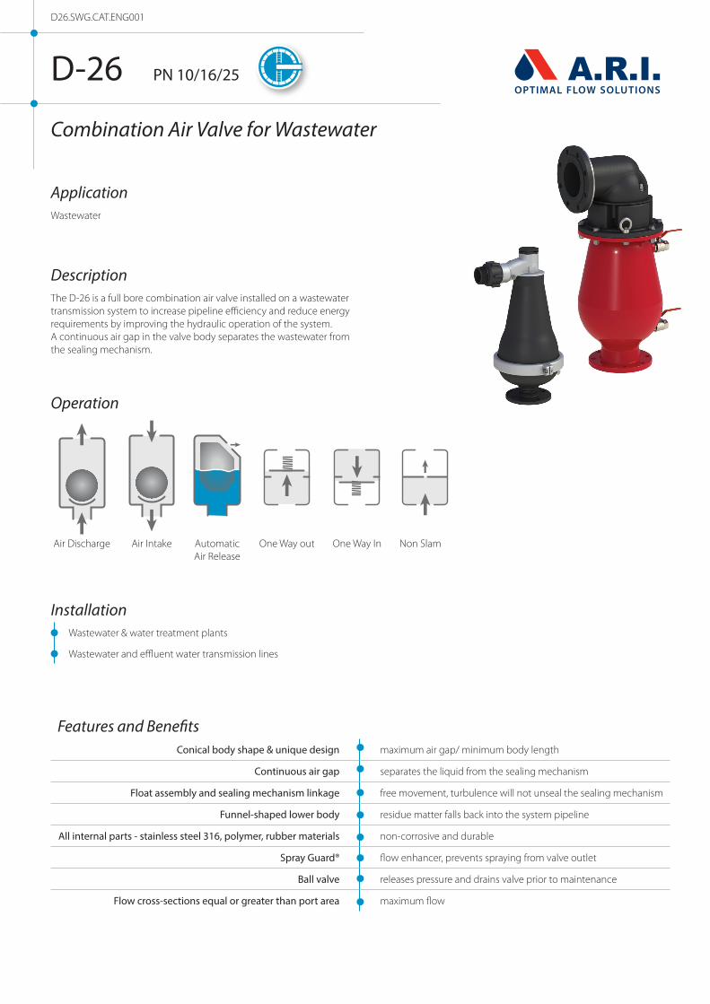
Combination Air Valve for Wastewater
DescriptionThe D-26 is a full bore combination air valve installed on a wastewater transmission system to increase pipeline efficiency and reduce energy requirements by improving the hydraulic operation of the system. A continuous air gap in the valve body separates the wastewater from the sealing mechanism.
ApplicationWastewater
D26.SWG.CAT.ENG001
Features and BenefitsConical body shape & unique design maximum air gap/ minimum body length
Continuous air gap separates the liquid from the sealing mechanism
Float assembly and sealing mechanism linkage free movement, turbulence will not unseal the sealing mechanism
Funnel-shaped lower body residue matter falls back into the system pipeline
All internal parts - stainless steel 316, polymer, rubber materials non-corrosive and durable
Spray Guard® flow enhancer, prevents spraying from valve outlet
Ball valve releases pressure and drains valve prior to maintenance
Flow cross-sections equal or greater than port area maximum flow
Installation Wastewater & water treatment plants
Wastewater and effluent water transmission lines
Operation
AutomaticAir Release
Air IntakeAir Discharge One Way out One Way In Non Slam

Valve Selection Options Flanged ends to meet any requested standard
Standard: cast ductile body, optional: stainless steel or 2" 3" reinforced nylon.
Optional Covers (for air discharge direction and for add-on components): 2” models - two-directional cover is standard 3” models - optional one directional and two-directional cover 4” models - one-directional elbow for horizontal discharge can be removed to allow for vertical discharge
Optional Add-on Components (2”, 3”, 4” sizes only) One-way, Out-only attachment, allows for air discharge only, prevents air intake. Vacuum Breaker, In-only attachment, allows for air intake only, prevents air discharge. Non-Slam discharge-throttling attachment, allows for free air intake, throttles air discharge.
Additional Product Configurations: Model D-26 NS with a built-in Non Slam Disc (6" & 8" sizes only) SB Underground Air Valve System
Technical Specifications
Size range: 2” –8”
Sealing pressure range: 2" - 8" 0.1-16 bar (PN 16) 2" 3" 0.02 -10 bar (PN 10) 3" metal 0.2 -25 bar (PN 25) Testing pressure: 1.5 times maximum working pressure
Maximum working temperature: 60° C. Maximum intermittent temperature: 90° C.
Valve coating: Fusion bonded epoxy coating in compliance with standard DIN 30677-2
Upon ordering, please specify: model, size, working pressure, thread/ flange standard and type of liquid
D-26 PN 10/16/25
Non-Slam Add-on Component Data Table for Variable Orifices
Size Number of orifices Discharge orifice
(mm)
Total NS area
(mm2)
NS orifice
(mm)
Switching point
(bar)
Flow at 0.4 bar
(m3/h)
2” (50mm)
1 orifice 50 15.9 4.5Spring loaded normally closed
24
2 orifices 50 31.8 6.4 31.6
3 orifices 50 47.7 7.8 40
3” (80mm)
1 orifice 75 50.3 8Spring loaded normally closed
38.47
2 orifices 75 100.5 11.3 72.51
3 orifices 75 150.8 13.9 111.38
4” (100mm)
1 orifice 100 78.5 10Spring loaded normally closed
150
2 orifices 100 157.1 14.1 185
3 orifices 100 235.6 17.3 230
6” (150mm) 1 orifice with graduated closure
150 706.86 30 0.025 1580
8” (200mm) 200 1641.3 45.7 0.0025 1890
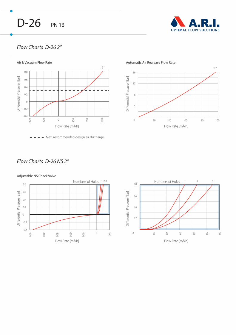
Flow Charts D-26 NS 2”
Flow Charts D-26 2”
D-26 PN 16
Max. recommended design air discharge
Air & Vacuum Flow Rate
Adjustable NS Chack Valve
Flow Rate [m3/h]
Flow Rate [m3/h]
Numbers of Holes Numbers of Holes
Flow Rate [m3/h]
Flow Rate [m3/h]
Diff
eren
tial P
ress
ure
[Bar
]D
iffer
entia
l Pre
ssur
e [B
ar]
Diff
eren
tial P
ress
ure
[Bar
]D
iffer
entia
l Pre
ssur
e [B
ar]
Automatic Air Realease Flow Rate

Flow Charts D-26 NS 3”
Flow Charts D-26 3”
D-26 PN 16/25
Max. recommended design air discharge
Air & Vacuum Flow Rate
Adjustable NS Chack Valve
Flow Rate [m3/h]
Flow Rate [m3/h]
Numbers of Holes Numbers of Holes
Flow Rate [m3/h]
Flow Rate [m3/h]
Diff
eren
tial P
ress
ure
[Bar
]D
iffer
entia
l Pre
ssur
e [B
ar]
Diff
eren
tial P
ress
ure
[Bar
]
Automatic Air Realease Flow Rate
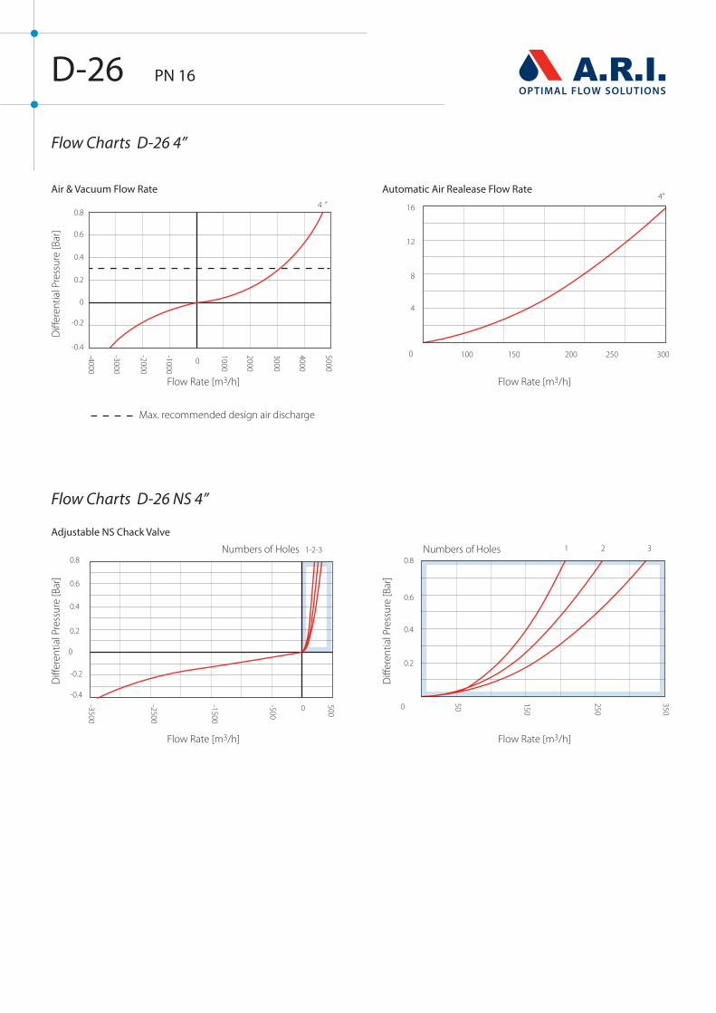
Flow Charts D-26 NS 4”
Flow Charts D-26 4”
D-26 PN 16
Max. recommended design air discharge
Air & Vacuum Flow Rate
Adjustable NS Chack Valve
Flow Rate [m3/h]
Flow Rate [m3/h]
Numbers of Holes Numbers of Holes
Flow Rate [m3/h]
Flow Rate [m3/h]
Diff
eren
tial P
ress
ure
[Bar
]D
iffer
entia
l Pre
ssur
e [B
ar]
Diff
eren
tial P
ress
ure
[Bar
]
Automatic Air Realease Flow Rate
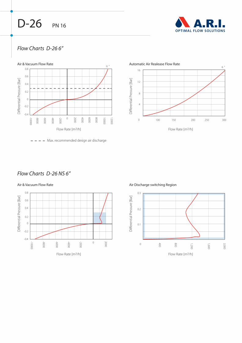
Flow Charts D-26 NS 6”
Flow Charts D-26 6”
D-26 PN 16
Max. recommended design air discharge
Air & Vacuum Flow Rate
Air & Vacuum Flow Rate Air Discharge switching Region
Flow Rate [m3/h]
Flow Rate [m3/h]
Flow Rate [m3/h]
Flow Rate [m3/h]
Diff
eren
tial P
ress
ure
[Bar
]
Diff
eren
tial P
ress
ure
[Bar
]
Diff
eren
tial P
ress
ure
[Bar
]
Diff
eren
tial P
ress
ure
[Bar
]
Automatic Air Realease Flow Rate

Flow Charts D-26 NS 8”
Flow Charts D-26 8”
D-26 PN 16
Max. recommended design air discharge
Air & Vacuum Flow Rate
Air & Vacuum Flow Rate Air Discharge switching Region
Flow Rate [m3/h]
Flow Rate [m3/h]
Flow Rate [m3/h]
Flow Rate [m3/h]
Diff
eren
tial P
ress
ure
[Bar
]
Diff
eren
tial P
ress
ure
[Bar
]
Diff
eren
tial P
ress
ure
[Bar
]
Diff
eren
tial P
ress
ure
[Bar
]
Automatic Air Realease Flow Rate

D-26 PN 10/16/25
Dimensions and Weight
Model Dimensions (mm) Connection Weight (kg) Orifice Area (mm2)
A B C RN ST ST A / V Auto.
D-26 2” (50 mm) THR 258 547 2" BSP / NPSM Female 8.1 13.2 1963 8.6
D-26 2” (50 mm) FL 258 554 2” BSP / NPSM Female 8.5 16.1 1963 8.6
D-26 NS 2” (50 mm) THR 330 547 2" BSP / NPSM Male 8.3 13.6 1963 8.6
D-26 NS 2” (50 mm) FL 330 554 2” BSP / NPSM Male 8.7 16.5 1963 8.6
One-directional cover DI ST ST
D-26 3” (80 mm) THR 526 580 3" BSP / NPSM Female 21.0 21.6 5024 15.7
D-26 3” (80 mm) FL 526 580 3” BSP / NPSM Female 21.6 24.6 5024 15.7
D-26 NS 3” (80 mm) THR 548 580 3" BSP / NPSM Male 21.8 22.5 5024 15.7
D-26 NS 3” (80 mm) FL 548 580 3” BSP / NPSM Male 24.7 25.5 5024 15.7
Two-directional cover DI ST ST
D-26 3” (80 mm) THR 495 620 3" BSP / NPSM Female 21.8 22.5 5024 15.7
D-26 3” (80 mm) FL 495 620 3” BSP / NPSM Female 24.2 25.0 5024 15.7
D-26 NS 3” (80 mm) THR 605 620 3" BSP / NPSM Male 22.7 23.4 5024 15.7
D-26 NS 3” (80 mm) FL 605 620 3” BSP / NPSM Male 24.7 25.4 5024 15.7
Two-directional cover (RN) RN
D-26 3” (80 mm) THR 350 613 3" BSP / NPSM Female 14.6 - 5024 15.7
D-26 3” (80 mm) FL 350 625 3” BSP / NPSM Female 15.4 - 5024 15.7
D-26 NS 3” (80 mm) THR 436 613 3" BSP / NPSM Male 15.4 - 5024 15.7
D-26 NS 3” (80 mm) FL 436 625 3” BSP / NPSM Male 16.1 - 5024 15.7
DI ST ST
D-26 4” (100 mm) FL 420 830 4" Flanged BSP / NPSM F 43.6 45 7854 31.14
D-26 NS 4” (100 mm) FL 607 849 4” Flanged BSP / NPSM F 48.5 50 7854 31.14
D-26 6” (150 mm) FL 545 889 6” Flanged BSP / NPSM F 86.3 89.0 17671 31.14
D-26 NS 6” (150 mm) FL 545 1002 6” Flanged BSP / NPSM F 91.2 94.0 17671 31.14
D-26 8” (200 mm) FL 552 1197 8” Flanged BSP / NPSM F 127.2 141.5 31400 31.14
D-26 NS 8” (200 mm) FL 552 1337 8” Flanged BSP / NPSM F 140.8 151.2 31400 31.14
NOTE The cover assembly with the discharge elbow can be set in four directions.Dimension A in the picture and in the table shows the maximum product width. This width can be reduced by changing the direction.
All product weights are approximate, due to the differences in flange standards, materials and variable accessories.
A
B
C

D-26 2" 3" PN 10/16
Parts List and Specification
Part Material
1. Cover Assembly
1a. Orifice Plug Polypropylene
1b. Cover Stainless Steel 316
1c. Bolt Assembly Stainless Steel 316 + Reinforced Nylon
1d. Non-Slam Component (Optional) Reinforced Nylon / Polypropylene + Stainless Steel
2. Seal Assembly
2a. Disc Arm Cast Stainless Steel
2b. Air&Vacuum Disc Cast Stainless Steel / Reinforced Nylon
2c. Air&Vacuum Seal EPDM
2d. Air Release Seal & Seat EPDM & Reinforced Nylon
2e. Seal Cover Reinforced Nylon
3. Body Assembly
3a. O-Ring BUNA-N
3b. Spray Guard® Polypropylene
3c. Body Reinforced Nylon / Stainless Steel 316
4. Float Assembly
4a. Domed Nut Stainless Steel 316
4b. Stopper Polypropylene
4c. Spring Stainless Steel 316
4d. Float & Rod Polypropylene + Stainless Steel 316
5. Base Assembly
5a. O-Ring BUNA-N
5b. Clamp Assembly Cast Stainless Steel + Stainless Steel 316
5c. Base Reinforced Nylon / Stainless Steel 316
5d. Tap Brass / Stainless Steel
3
2
4
1
5

D-26 3" PN 25
Parts List and Specification
Part Material
1. Cover Assembly Materials
1a. Orifice Plug Polypropylene
1b. Cover Ductile Iron
1c. Bolt Assembly Stainless Steel 316 + Reinforced Nylon
1d. Orifice Seat Stainless Steel 316
1e. Non-Slam Component (Optional) Reinforced Nylon / Polypropylene + Stainless Steel
2. Seal Assembly
2a. Disc Arm Cast Stainless Steel
2b. Air&Vacuum Disc Cast Stainless Steel
2c. Air&Vacuum Seal EPDM
2d. Air Release Seal & Seat EPDM & Reinforced Nylon
2e. Seal Cover Reinforced Nylon
3. Float Assembly
3a. Domed Nut Stainless Steel 316
3b. Stopper Polypropylene
3c. Spring Stainless Steel 316
3d. Float & Rod Polypropylene + Stainless Steel 316
4. Body Assembly
4a. Spray Guard® BUNA-N
4b. O-Ring Polypropylene
4c. Body Cast Steel / Stainless Steel 316
4d. Ball Valve Brass, Chrome Coated /Stainless Steel 316
3
2
1
4

D-26 3" PN 16
Parts List and Specification
Part Material
1. Cover Assembly Materials
1a. Orifice Plug Polypropylene
1b. Cover Stainless Steel 316
1c. Bolt Assembly Stainless Steel 316 + Reinforced Nylon
1d. Non-Slam Component (Optional) Reinforced Nylon / Polypropylene + Stainless Steel
2. Seal Assembly
2a. Disc Arm Cast Stainless Steel
2b. Air&Vacuum Disc Cast Stainless Steel / Reinforced Nylon
2c. Air&Vacuum Seal EPDM
2d. Air Release Seal & Seat EPDM & Reinforced Nylon
2e. Seal Cover Reinforced Nylon
3. Float Assembly
3a. Domed Nut Stainless Steel 316
3b. Stopper Polypropylene
3c. Spring Stainless Steel 316
3d. Float & Rod Polypropylene + Stainless Steel 316
4. Body Assembly
4a. O-Ring BUNA-N
4b. Spray Guard® Polypropylene
4c. Body Cast Steel / Stainless Steel 316
4d. Ball Valve Brass, Chrome Coated / Stainless Steel 316
3
2
1
4

3
2
1
4
D-26 4" PN 16
Parts List and Specification
Part Material
1. Cover Assembly
1a. Discharge Elbow PVC
1b. Cover Ductile Iron / Stainless Steel 316
1c. Orifice Seat Stainless Steel 316
1d. Non-Slam Component (Optional) Reinforced Nylon / Polypropylene + Stainless Steel
2. Seal Assembly
2a. Guide Rod Assembly Stainless Steel 316 + Acetal
2b. Air&Vacuum Disc Cast Stainless Steel
2c. Air&Vacuum Seal EPDM
2d. Air Release Seal & Seat EPDM & Reinforced Nylon
2e. Seal Cover Assembly Reinforced Nylon
2f. Flow Enhancer ABS
3. Float Assembly
3a. Domed Nut Stainless Steel 316
3b. Stopper Polypropylene
3c. Spring Stainless Steel 316
3d. Float & Rod Polypropylene + Stainless Steel 316
4. Body Assembly
4a. O-Ring BUNA-N
4b. Body Cast Steel / Stainless Steel 316
4c. Plug Stainless Steel 316
4d. Ball Valve Brass, Chrome Coated / Stainless Steel 316

Parts List and Specification
Part Material
1. Discharge Elbow Assembly Materials
1a. Flange Supports Stainless Steel 316
1b. Discharge Elbow Polyethylene
1c. Angle Support Stainless Steel 316
2. Cover Assembly
2a. Seal NBR
2b. Cover Ductile Iron / Stainless Steel 316
2c. Orifice Seat Stainless Steel 316
3. Seal Assembly
3a. Guide Rod Assembly Stainless Steel 316 + Acetal
3b. Air&Vacuum Disc Cast Stainless Steel
3c. Air&Vacuum Seal EPDM
3d. Air Release Seal & Seat EPDM & Reinforced Nylon
3e. Seal Cover Assembly Reinforced Nylon
3f. Flow Enhancer ABS
4. Float Assembly
4a. Domed Nut Stainless Steel 316
4b. Stopper Polypropylene
4c. Spring Stainless Steel 316
4d. Float & Rod Polypropylene + Stainless Steel 316
5. Body Assembly
5a. O-Ring BUNA-N
5b. Body Cast Steel / Stainless Steel 316
5c.Ball Valves Brass, Chrome Coated / Stainless Steel 316
D-26 6" PN 16
3
2
1
4
5

D-26 NS 6" PN 16
Parts List and Specification
Part Material
1. Discharge Elbow Assembly
1a. Flange Supports Stainless Steel 316
1b. Discharge Elbow Polyethylene
1c. Angle Support Stainless Steel 316
1d. Seal NBR
2. Non-Slam Assembly - Optional
2a. Ring Stainless Steel 316
2b. Ring Seal EPDM
2c. Disc Housing Polyethylene
2d. Non-slam Disc Stainless Steel 316 / Ductile Iron
2e. Threaded Rods Stainless Steel 316
3. Cover Assembly
3a. Seal NBR
3b. Cover Ductile Iron / Stainless Steel 316
3c. Orifice Seat Stainless Steel 316
4. Seal Assembly
4a. Guide Rod Assembly Stainless Steel 316 + Acetal
4b. Air&Vacuum Disc Cast Stainless Steel
4c. Air&Vacuum Seal EPDM
4d. Air Release Seal & Seat EPDM & Reinforced Nylon
4e. Seal Cover Assembly Reinforced Nylon
5. Float Assembly
5a. Domed Nut Stainless Steel 316
5b. Stopper Polypropylene
5c. Spring Stainless Steel 316
5d. Float & Rod Polypropylene + Stainless Steel 316
6. Body Assembly
6a. O-Ring BUNA-N
6b. Body Cast Steel / Stainless Steel 316
6c. Ball Valves Brass, Chrome Coated / Stainless Steel 316
3
2
1
4
5
6

Parts List and Specification
Part Material
1. Discharge Elbow Assembly Materials
1a. Flange Supports Stainless Steel 316
1b. Discharge Elbow Polyethylene
1c. Angle Support Stainless Steel 316
2. Cover Assembly
2a. Seal NBR
2b. Cover Ductile Iron / Stainless Steel 316
2c. Orifice Seat Stainless Steel 316
3. Seal Assembly
3a. Guide Rod Assembly Stainless Steel 316 + Acetal
3b. Air&Vacuum Disc Cast Stainless Steel
3c. Air&Vacuum Seal EPDM
3d. Air Release Seal & Seat EPDM & Reinforced Nylon
3e. Seal Cover Assembly Reinforced Nylon
3f. Flow Enhancer ABS
4. Float Assembly
4a. Domed Nut Stainless Steel 316
4b. Stopper Polypropylene
4c. Spring Stainless Steel 316
4d. Float & Rod Polypropylene + Stainless Steel 316
5. Body Assembly
5a. O-Ring BUNA-N
5b.Body Cast Steel / Stainless Steel 316
5c. Ball Valves Brass, Chrome Coated / Stainless Steel 316
D-26 8" PN 16
3
2
1
4
5

A.R.I. FLOW CONTROL ACCESSORIES Ltd. reserves the right to make product changes without prior notice. To insure receiving updated information on parts specifications, please call the export dept. at the A.R.I. factory. A.R.I. FLOW CONTROL ACCESSORIES Ltd. shall not be held liable for any errors. All rights reserved.
A.R.I. FLOW CONTROL ACCESSORIES Ltd. www.arivalves.com [email protected] Tel: 972-4-6761988
D-26 NS 8" PN 16
Parts List and Specification
Part Material
1. Discharge Elbow Assembly
1a. Flange Supports Stainless Steel 316
1b. Discharge Elbow Polyethylene
1c. Angle Support Stainless Steel 316
2. Non-Slam Assembly - Optional
2a. Ring Stainless Steel 316
2b. Ring Seal EPDM
2c. Disc Housing Polyethylene
2d. Non-slam Disc Stainless Steel 316 / Ductile Iron
2e. Threaded Rods Stainless Steel 316
3. Cover Assembly
3a. Seal NBR
3b. Cover Ductile Iron / Stainless Steel 316
3c. Orifice Seat Stainless Steel 316
4. Seal Assembly
4a. Guide Rod Assembly Stainless Steel 316 + Acetal
4b. Air&Vacuum Disc Cast Stainless Steel
4c. Air&Vacuum Seal EPDM
4d. Air Release Seal & Seat EPDM & Reinforced Nylon
4e. Seal Cover Assembly Reinforced Nylon
5. Float Assembly
5a. Domed Nut Stainless Steel 316
5b. Stopper Polypropylene
5c. Spring Stainless Steel 316
5d. Float & Rod Polypropylene + Stainless Steel 316
6. Body Assembly
6a. O-Ring BUNA-N
6b.Body Cast Steel / Stainless Steel 316
6c. Ball Valves Brass, Chrome Coated / Stainless Steel 316
3
2
1
4
5
6


![Wastewater Treatment by Biological Processes · Wastewater Treatment by Biological Processes ... or by a combination of chemical treatment and settling [8]. ... wastewater treatment,](https://cdn.vdocuments.site/doc/165x107/5b62ba727f8b9a54488ddaac/wastewater-treatment-by-biological-wastewater-treatment-by-biological-processes.jpg)

