
CMSC 332: Computer Networks
CMSC 332 Computer Networks
TCP (1)
Professor Szajda

CMSC 332: Computer Networks
Bits? Bytes? Kilo-huh?
• A number of students have pointed out that there is a difference between the way networking and other areas represent “kilo” units.
‣ i.e., KB
‣ Some have proposed “kibi-”, “mibi-” and “gibi-” instead.
• In networking, “Kilo” is treated as 1000, not 1024.
• Some problems may ask you to show the difference between KB transferred and KB stored. This is the reason.
2

CMSC 332: Computer Networks
Last Time
• Discussed a variety of algorithms that can give us guarantees of reliable delivery.
‣ What were they?
‣ How do they differ?
• Finite State Machines (FSMs) are a powerful means of representing protocols.
3

CMSC 332: Computer Networks
Chapter 3 outline
• 3.1 Transport-layer services
• 3.2 Multiplexing and demultiplexing
• 3.3 Connectionless transport: UDP
• 3.4 Principles of reliable data transfer
• 3.5 Connection-oriented transport: TCP ‣ segment structure ‣ reliable data transfer ‣ flow control ‣ connection management
• 3.6 Principles of congestion control
• 3.7 TCP congestion control
4
CMSC 332: Computer Networks
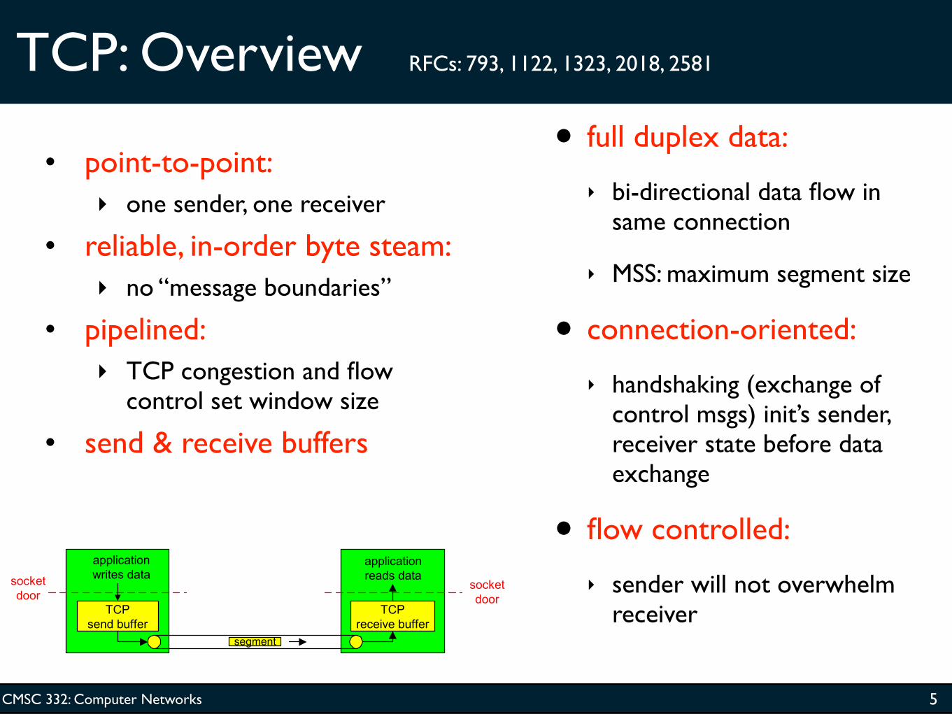
TCP: Overview RFCs: 793, 1122, 1323, 2018, 2581
• full duplex data:
‣ bi-directional data flow in same connection
‣ MSS: maximum segment size
• connection-oriented:
‣ handshaking (exchange of control msgs) init’s sender, receiver state before data exchange
• flow controlled:
‣ sender will not overwhelm receiver
• point-to-point: ‣ one sender, one receiver
• reliable, in-order byte steam: ‣ no “message boundaries”
• pipelined: ‣ TCP congestion and flow
control set window size • send & receive buffers
5
CMSC 332: Computer Networks
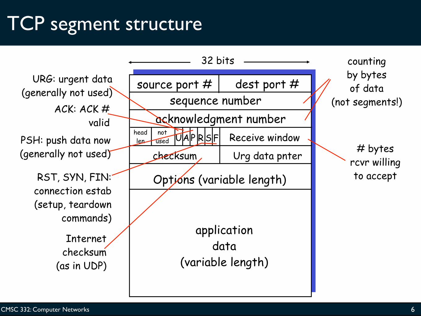
TCP segment structure
source port # dest port #
32 bits
application data
(variable length)
sequence numberacknowledgment number
Receive window
Urg data pnterchecksum
FSRPAUhead len
not used
Options (variable length)
URG: urgent data (generally not used)
ACK: ACK # valid
PSH: push data now (generally not used)
RST, SYN, FIN: connection estab (setup, teardown
commands)
Internet checksum
(as in UDP)
# bytes rcvr willing to accept
counting by bytes of data
(not segments!)
6

CMSC 332: Computer Networks
TCP seq. #’s and ACKs
Seq. #’s:
‣ byte stream “number” of first byte in segment’s data
ACKs:
‣ seq # of next byte expected from other side
‣ cumulative ACK
Q: how receiver handles out-of-order segments
‣ A: TCP spec doesn’t say, - up to implementor
Host A
Host B
Seq=42, ACK=79, data = ‘C’
Seq=79, ACK=43, data = ‘C’
Seq=43, ACK=80
User types
‘C’
host ACKs receipt
of echoed ‘C’
host ACKs receipt of ‘C’, echoes
back ‘C’
timesimple telnet scenario
7

CMSC 332: Computer Networks
TCP Round Trip Time and Timeout
Q: how to set TCP timeout value?
• longer than RTT
‣ but RTT varies
• too short: premature timeout
‣ unnecessary retransmissions
• too long: slow reaction to segment loss
Q: how to estimate RTT? • SampleRTT: measured time from
segment transmission until ACK receipt ‣ ignore retransmissions
• SampleRTT will vary, want estimated RTT “smoother”
‣ average several recent measurements, not just current SampleRTT
8

CMSC 332: Computer Networks
TCP Round Trip Time and Timeout
EstimatedRTT = (1- α)*EstimatedRTT + α*SampleRTT
• Exponential weighted moving average• influence of past sample decreases exponentially fast• typical value: α = 0.125
9

CMSC 332: Computer Networks
Example RTT estimation:
10

CMSC 332: Computer Networks
TCP Round Trip Time and Timeout
Setting the timeout
• EstimtedRTT plus “safety margin”
‣ large variation in EstimatedRTT -> larger safety margin
• first estimate of how much SampleRTT deviates from EstimatedRTT:
TimeoutInterval = EstimatedRTT + 4*DevRTT
DevRTT = (1-β)*DevRTT + β*|SampleRTT-EstimatedRTT|
(typically, β = 0.25)
Then set timeout interval:
11

CMSC 332: Computer Networks
Chapter 3 outline
• 3.1 Transport-layer services
• 3.2 Multiplexing and demultiplexing
• 3.3 Connectionless transport: UDP
• 3.4 Principles of reliable data transfer
• 3.5 Connection-oriented transport: TCP ‣ segment structure
‣ reliable data transfer
‣ flow control
‣ connection management • 3.6 Principles of congestion
control• 3.7 TCP congestion control
12

CMSC 332: Computer Networks
TCP reliable data transfer
• TCP creates rdt service on top of IP’s unreliable service
• Pipelined segments
• Cumulative acks
• TCP uses single retransmission timer
• Retransmissions are triggered by: ‣ timeout events
‣ duplicate acks • Initially consider simplified
TCP sender: ‣ ignore duplicate acks
‣ ignore flow control, congestion control
13

CMSC 332: Computer Networks
TCP sender events:
data rcvd from app:
• Create segment with seq #
• seq # is byte-stream number of first data byte in segment
• start timer if not already running (think of timer as for oldest unacked segment)
• expiration interval: TimeOutInterval
timeout: • retransmit segment that
caused timeout• restart timer Ack rcvd: • If acknowledges previously
unacked segments ‣ update what is known to be
acked
‣ start timer if there are outstanding segments
14

CMSC 332: Computer Networks
TCP sender (simplified)
NextSeqNum = InitialSeqNum SendBase = InitialSeqNum
loop (forever) { switch(event)
event: data received from application above create TCP segment with sequence number NextSeqNum if (timer currently not running) start timer pass segment to IP NextSeqNum = NextSeqNum + length(data)
event: timer timeout retransmit not-yet-acknowledged segment with smallest sequence number start timer
event: ACK received, with ACK field value of y if (y > SendBase) { SendBase = y if (there are currently not-yet-acknowledged segments) start timer }
} /* end of loop forever */
Comment: • SendBase-1: last cumulatively ack’ed byte Example:• SendBase-1 = 71; y= 73, so the rcvr wants 73+ ; y > SendBase, so that new data is acked
15

CMSC 332: Computer Networks
TCP: retransmission scenarios
Host A
Seq=100, 20 bytes data
ACK=100
timepremature timeout
Host B
Seq=92, 8 bytes data
ACK=120
Seq=92, 8 bytes data
Seq=
92 t
imeo
ut
ACK=120
Host A
Seq=92, 8 bytes data
ACK=100
loss
tim
eout
lost ACK scenario
Host B
XSeq=92, 8 bytes data
ACK=100
time
Seq=
92 t
imeo
utSendBase
= 100
SendBase = 120
SendBase = 120
Sendbase = 100
16

CMSC 332: Computer Networks
TCP retransmission scenarios (more)
Host A
Seq=92, 8 bytes data
ACK=100
loss
tim
eout
Cumulative ACK scenario
Host B
XSeq=100, 20 bytes data
ACK=120
time
SendBase = 120
17

CMSC 332: Computer Networks
TCP ACK generation [RFC 1122, RFC 2581]
Event at Receiver Arrival of in-order segment with expected seq #. All data up to
expected seq # already ACKed
Arrival of in-order segment with expected seq #. One other segment has ACK pending
Arrival of out-of-order segment higher-than-expect seq. # .
Gap detected
Arrival of segment that partially or completely fills gap
TCP Receiver action Delayed ACK. Wait up to 500ms
for next segment. If no next segment, send ACK
Immediately send single cumulative ACK, ACKing both in-order segments
Immediately send duplicate ACK, indicating seq. # of next expected byte
Immediate send ACK, provided that segment startsat lower end of gap
18
CMSC 332: Computer Networks
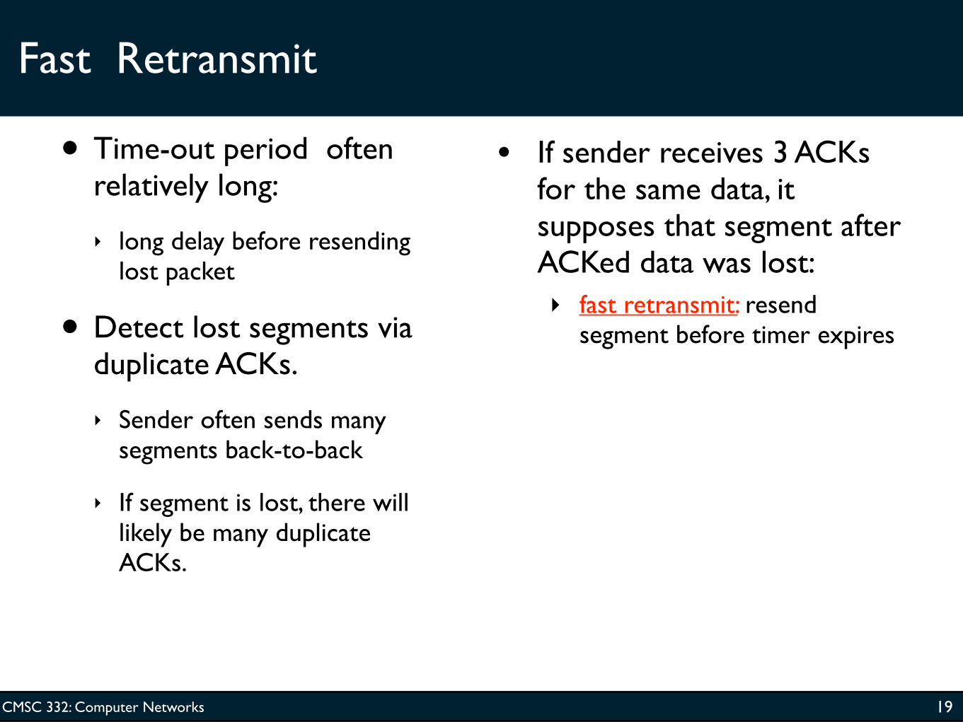
Fast Retransmit
• Time-out period often relatively long:
‣ long delay before resending lost packet
• Detect lost segments via duplicate ACKs.
‣ Sender often sends many segments back-to-back
‣ If segment is lost, there will likely be many duplicate ACKs.
• If sender receives 3 ACKs for the same data, it supposes that segment after ACKed data was lost: ‣ fast retransmit: resend
segment before timer expires
19

CMSC 332: Computer Networks
Fast Retransmit
20
Host A
tim
eout
Host B
time
X
resend 2nd segment
Figure 3.37 Resending a segment after triple duplicate ACK

CMSC 332: Computer Networks
event: ACK received, with ACK field value of y if (y > SendBase) { SendBase = y if (there are currently not-yet-acknowledged segments) start timer } else { increment count of dup ACKs received for y if (count of dup ACKs received for y = 3) { resend segment with sequence number y }
Fast retransmit algorithm:
a duplicate ACK for already ACKed segment
fast retransmit
21

CMSC 332: Computer Networks
Chapter 3 outline
• 3.1 Transport-layer services
• 3.2 Multiplexing and demultiplexing
• 3.3 Connectionless transport: UDP
• 3.4 Principles of reliable data transfer
• 3.5 Connection-oriented transport: TCP ‣ segment structure
‣ reliable data transfer
‣ flow control
‣ connection management • 3.6 Principles of congestion
control• 3.7 TCP congestion control
22

CMSC 332: Computer Networks
TCP Flow Control
• receive side of TCP connection has a receive buffer:
• speed-matching service: matching the send rate to the receiving app’s drain rate
• app process may be slow at reading from buffer
sender won’t overflowreceiver’s buffer by
transmitting too much, too fast
flow control
23

CMSC 332: Computer Networks
TCP Flow control: how it works
(Suppose TCP receiver discards out-of-order segments)
• spare room in buffer
= RcvWindow
= RcvBuffer-[LastByteRcvd - LastByteRead]
• Rcvr advertises spare room by including value of RcvWindow in segments
• Sender limits unACKed data to RcvWindow ‣ guarantees receive buffer
doesn’t overflow
24

CMSC 332: Computer Networks
Chapter 3 outline
• 3.1 Transport-layer services
• 3.2 Multiplexing and demultiplexing
• 3.3 Connectionless transport: UDP
• 3.4 Principles of reliable data transfer
• 3.5 Connection-oriented transport: TCP ‣ segment structure
‣ reliable data transfer
‣ flow control
‣ connection management • 3.6 Principles of congestion
control• 3.7 TCP congestion control
25

CMSC 332: Computer Networks
TCP Connection Management
Recall: TCP sender, receiver establish “connection” before exchanging data segments
• initialize TCP variables:
‣ seq. #s
‣ buffers, flow control info (e.g. RcvWindow)
• client: connection initiator
connect(sock, &addr, ...);
• server: contacted by client
accept(sock, &addr, ...);
Three way handshake:
Step 1: client host sends TCP SYN segment to server ‣ specifies initial seq #
‣ no data Step 2: server host receives
SYN, replies with SYNACK segment
‣ server allocates buffers
‣ specifies server initial seq. # Step 3: client receives SYNACK,
replies with ACK segment, which may contain data
26

CMSC 332: Computer Networks
TCP Connection Management (cont.)
Closing a connection:
client closes socket:
close(sock);
Step 1: client end system sends TCP FIN control segment to server
Step 2: server receives FIN, replies with ACK. Closes connection, sends FIN.
client
FIN
server
ACK
ACK
FIN
close
close
closed
tim
ed w
ait
27

CMSC 332: Computer Networks
TCP Connection Management (cont.)
Step 3: client receives FIN, replies with ACK.
‣ Enters “timed wait” - will respond with ACK to received FINs
Step 4: server, receives ACK. Connection closed.
Note: with small modification, can handle simultaneous FINs.
client
FIN
server
ACK
ACK
FIN
closing
closing
closed
tim
ed w
ait
closed
28

CMSC 332: Computer Networks
TCP Connection Management (cont)
TCP client lifecycle
TCP server lifecycle
29

CMSC 332: Computer Networks
SYN Flooding
• Classic Internet attack sends a huge number of SYN packets to a host, but never responds with the third handshake message.
• In so doing, an adversary forces a receiver to dedicate a huge amount of resources to bogus requests.
‣ And therefore makes those resources unavailable to legitimate users.
• There are ways to prevent this (SYN Cookies), but a surprising number of systems are still vulnerable.
30

CMSC 332: Computer Networks
Chapter 3 outline
• 3.1 Transport-layer services
• 3.2 Multiplexing and demultiplexing
• 3.3 Connectionless transport: UDP
• 3.4 Principles of reliable data transfer
• 3.5 Connection-oriented transport: TCP ‣ segment structure
‣ reliable data transfer
‣ flow control
‣ connection management • 3.6 Principles of congestion
control• 3.7 TCP congestion control
31

CMSC 332: Computer Networks
Principles of Congestion Control
Congestion:
• informally: “too many sources sending too much data too fast for network to handle”
• different from flow control!
• manifestations:
‣ lost packets (buffer overflow at routers)
‣ long delays (queueing in router buffers)
• a top-10 problem!
32

CMSC 332: Computer Networks
Causes/costs of congestion: scenario 1
• two senders, two receivers
• one router, infinite buffers
• no retransmission
• large delays when congested
• maximum achievable throughput
unlimited shared output link buffers
Host Aλin : original data
Host B
λout
33

CMSC 332: Computer Networks
Causes/costs of congestion: scenario 2
• one router, finite buffers
• sender retransmission of lost packet
finite shared output link buffers
Host A λin : original data
Host B
λout
λ'in : original data, plus retransmitted data
34

CMSC 332: Computer Networks
Causes/costs of congestion: scenario 2
• always: (goodput)
• “perfect” retransmission only when loss:
• retransmission of delayed (not lost) packet makes larger (than perfect
case) for same
λinλ
out=
λin
λout>
λin
λout
“costs” of congestion: • more work (retrans) for given “goodput”• unneeded retransmissions: link carries multiple copies of pkt
R/2
R/2λin
λ out
b.
R/2
R/2λin
λ out
a.
R/2
R/2λin
λ out
c.
R/4
R/3
35

CMSC 332: Computer Networks
Causes/costs of congestion: scenario 3
• four senders
• multihop paths
• timeout/retransmit
λinQ: what happens as
and increase?λin
finite shared output link buffers
Host Aλin : original data
Host B
λout
λ'in : original data, plus retransmitted data
36

CMSC 332: Computer Networks
Causes/costs of congestion: scenario 3
Another “cost” of congestion: • when packet dropped, any “upstream transmission capacity
used for that packet was wasted!
Host A
Host B
λ
ou
t
37

CMSC 332: Computer Networks
Approaches towards congestion control
End-end congestion control:
• no explicit feedback from network
• congestion inferred from end-system observed loss, delay
• approach taken by TCP
Network-assisted congestion control:• routers provide feedback to end systems
‣ single bit indicating congestion (SNA, DECbit, TCP/IP ECN, ATM)
‣ explicit rate sender should send at
Two broad approaches towards congestion control:
38

CMSC 332: Computer Networks
Case study: ATM ABR congestion control
ABR: available bit rate:
• “elastic service”
• if sender’s path “underloaded”:
‣ sender should use available bandwidth
• if sender’s path congested:
‣ sender throttled to minimum guaranteed rate
RM (resource management) cells:• sent by sender, interspersed with
data cells• bits in RM cell set by switches
(“network-assisted”)
‣ NI bit: no increase in rate (mild congestion)
‣ CI bit: congestion indication• RM cells returned to sender by
receiver, with bits intact
39

CMSC 332: Computer Networks
Case study: ATM ABR congestion control
• two-byte ER (explicit rate) field in RM cell
‣ congested switch may lower ER value in cell
‣ sender’ send rate thus maximum supportable rate on path
• EFCI bit in data cells: set to 1 in congested switch
‣ if data cell preceding RM cell has EFCI set, sender sets CI bit in returned RM cell
40

CMSC 332: Computer Networks
Next Time
• Read Section 3.7
‣ Congestion control in TCP
41


