
Internetworking With TCP/IP
Chapter 4:Network Layer & Routing
Ethernet, IEEE 802.3, Token Ring, X.25, SNA, FDDI, ….
TCP UDP
Telnet Gopher NFS
FTP X Win TFTP
SMTP SNMP
REXEC DNS RPC
Application Layer
Transport Layer
Network Layer
Link Interface
ICMP IGMPIP RARPARP
Parviz KermaniNYU:Poly

Network Layer 4-2
Chapter 4Network Layer
Computer Networking: A Top Down Approach 5th edition. Jim Kurose, Keith RossAddison-Wesley, April 2009.
A note on the use of these ppt slides:We’re making these slides freely available to all (faculty, students, readers). They’re in PowerPoint form so you see the animations; and can add, modify, and delete slides (including this one) and slide content to suit your needs. They obviously represent a lot of work on our part. In return for use, we only ask the following: If you use these slides (e.g., in a class) that you mention their source
(after all, we’d like people to use our book!) If you post any slides on a www site, that you note that they are adapted
from (or perhaps identical to) our slides, and note our copyright of this material.
Thanks and enjoy! JFK/KWR
All material copyright 1996-2011J.F Kurose and K.W. Ross, All Rights Reserved

Legends Back to previous foil
Page contains animation
End of animation
Network Layer 4-3
Note: The original of these foils were provided by the authors. There are additions/deletions made by me, Parviz Kermani.

Chapter 4: network layerchapter goals: understand principles behind network layer
services: network layer service models forwarding versus routing how a router works routing (path selection) broadcast, multicast
instantiation, implementation in the Internet
Network Layer 4-4

Chapter 4: outline4.1 introduction4.2 virtual circuit and
datagram networks4.3 what’s inside a router4.4 IP: Internet Protocol
datagram format IPv4 addressing ICMP IPv6
4.5 routing algorithms link state distance vector hierarchical routing
4.6 routing in the Internet RIP OSPF BGP
4.7 broadcast and multicast routing
Network Layer 4-5

Network layer
transport segment from sending to receiving host
on sending side encapsulates segments into datagrams
on receiving side, delivers segments to transport layer
network layer protocols in every host, router
router examines header fields in all IP datagrams passing through it
Network Layer 4-6
applicationtransportnetworkdata linkphysical
applicationtransportnetworkdata linkphysical
networkdata linkphysical network
data linkphysical
networkdata linkphysical
networkdata linkphysical
networkdata linkphysical
networkdata linkphysical
networkdata linkphysical
networkdata linkphysical
networkdata linkphysical
networkdata linkphysicalnetwork
data linkphysical

Two key network-layer functions forwarding: move
packets from router’s input to appropriate router output
routing: determine route taken by packets from source to dest.
routing algorithms
analogy:
routing: process of planning trip from source to dest
forwarding: process of getting through single interchange
Network Layer 4-7

Interplay between routing and forwarding
Network Layer 4-8
1
23
0111
value in arrivingpacket’s header
routing algorithm
local forwarding tableheader value output link
0100010101111001
3221
routing algorithm determinesend-end-path through network
forwarding table determineslocal forwarding at this router

Connection setup 3rd important function in some network
architectures: ATM, frame relay, X.25
before datagrams flow, two end hosts andintervening routers establish virtual connection routers get involved
network vs transport layer connection service: network: between two hosts (may also involve
intervening routers in case of VCs) transport: between two processes
Network Layer 4-9

Network service model
example services for individual datagrams:
guaranteed delivery guaranteed delivery with
less than 40 msec delay
example services for a flow of datagrams:
in-order datagram delivery
guaranteed minimum bandwidth to flow
restrictions on changes in inter-packet spacing
Network Layer 4-10
Q: What service model for “channel” transporting datagrams from sender to receiver?

Network layer service models:
Network Layer 4-11
NetworkArchitecture
Internet
ATM
ATM
ATM
ATM
ServiceModel
best effort
CBR
VBR
ABR
UBR
Bandwidth
none
constantrateguaranteedrateguaranteed minimumnone
Loss
no
yes
yes
no
no
Order
no
yes
yes
yes
yes
Timing
no
yes
yes
no
no
Congestionfeedback
no (inferredvia loss)nocongestionnocongestionyes
no
Guarantees ?

Chapter 4: outline4.1 introduction4.2 virtual circuit and
datagram networks4.3 what’s inside a router4.4 IP: Internet Protocol
datagram format IPv4 addressing ICMP IPv6
4.5 routing algorithms link state distance vector hierarchical routing
4.6 routing in the Internet RIP OSPF BGP
4.7 broadcast and multicast routing
Network Layer 4-12

Connection, connection-less service
datagram network provides network-layer connectionless service
virtual-circuit network provides network-layer connection service
analogous to TCP/UDP connecton-oriented / connectionless transport-layer services, but: service: host-to-host no choice: network provides one or the other implementation: in network core
Network Layer 4-13

Virtual circuits
call setup, teardown for each call before data can flow each packet carries VC identifier (not destination host
address) every router on source-dest path maintains “state” for
each passing connection link, router resources (bandwidth, buffers) may be
allocated to VC (dedicated resources = predictable service)
Network Layer 4-14
“source-to-dest path behaves much like telephone circuit” performance-wise network actions along source-to-dest path

VC implementationa VC consists of:
1. path from source to destination2. VC numbers, one number for each link along path3. entries in forwarding tables in routers along path
packet belonging to VC carries VC number (rather than dest address)
VC number can be changed on each link. new VC number comes from forwarding table
Network Layer 4-15

VC forwarding table
Network Layer 4-16
12 22 32
1 23
VC numberinterfacenumber
Incoming interface Incoming VC # Outgoing interface Outgoing VC #
1 12 3 222 63 1 18 3 7 2 171 97 3 87… … … …
forwarding table innorthwest router:
VC routers maintain connection state information!

Virtual circuits: signaling protocols
used to setup, maintain teardown VC used in ATM, frame-relay, X.25 not used in today’s Internet
Network Layer 4-17
applicationtransportnetworkdata linkphysical
1. initiate call 2. incoming call3. accept call4. call connected
5. data flow begins 6. receive dataapplicationtransportnetworkdata linkphysical

Datagram networks
no call setup at network layer routers: no state about end-to-end connections no network-level concept of “connection”
packets forwarded using destination host address
Network Layer 4-18
1. send datagrams
applicationtransportnetworkdata linkphysical
applicationtransportnetworkdata linkphysical
2. receive datagrams

Datagram forwarding table
Network Layer 4-19
1
23
IP destination address in arriving packet’s header
routing algorithm
local forwarding tabledest address output link
address-range 1address-range 2address-range 3address-range 4
3221
4 billion IP addresses, so rather than list individual destination addresslist range of addresses(aggregate table entries)

Datagram forwarding table
Network Layer 4-20
Destination Address Range
11001000 00010111 00010000 00000000through11001000 00010111 00010111 11111111
11001000 00010111 00011000 00000000through11001000 00010111 00011000 11111111
11001000 00010111 00011001 00000000through11001000 00010111 00011111 11111111
otherwise
Link Interface
0
1
2
3
Q: but what happens if ranges don’t divide up so nicely?

Longest prefix matching
Network Layer 4-21
Destination Address Range
11001000 00010111 00010*** *********
11001000 00010111 00011000 *********
11001000 00010111 00011*** *********
otherwise
DA: 11001000 00010111 00011000 10101010
examples:DA: 11001000 00010111 00010110 10100001 which interface?
which interface?
when looking for forwarding table entry for given destination address, use longest address prefix that matches destination address.
longest prefix matching
Link interface
0
1
2
3

Datagram or VC network: why?Internet (datagram) data exchange among
computers “elastic” service, no strict
timing req.
many link types different characteristics uniform service difficult
“smart” end systems (computers) can adapt, perform control,
error recovery simple inside network,
complexity at “edge”
ATM (VC) evolved from telephony human conversation:
strict timing, reliability requirements
need for guaranteed service “dumb” end systems
telephones complexity inside
network
Network Layer 4-22

Chapter 4: outline4.1 introduction4.2 virtual circuit and
datagram networks4.3 what’s inside a router4.4 IP: Internet Protocol
datagram format IPv4 addressing ICMP IPv6
4.5 routing algorithms link state distance vector hierarchical routing
4.6 routing in the Internet RIP OSPF BGP
4.7 broadcast and multicast routing
Network Layer 4-23

Router architecture overview
two key router functions: run routing algorithms/protocol (RIP, OSPF, BGP) forwarding datagrams from incoming to outgoing link
Network Layer 4-24
switchingfabric
routing processor
router input ports router output ports

Input port functions
Network Layer 4-25
decentralized switching: given datagram dest., lookup output port
using forwarding table in input port memory
goal: complete input port processing at ‘line speed’
queuing: if datagrams arrive faster than forwarding rate into switch fabric
linetermination
link layer
protocol(receive)
lookup,forwarding
queueing
physical layer:bit-level reception
data link layer:e.g., Ethernetsee chapter 5
switchfabric

Switching fabrics
transfer packet from input buffer to appropriate output buffer
switching rate: rate at which packets can be transfer from inputs to outputs often measured as multiple of input/output line rate N inputs: switching rate N times line rate desirable
three types of switching fabrics
Network Layer 4-26
memory
memory
bus crossbar

Switching via memory
first generation routers: traditional computers with switching under direct control
of CPU packet copied to system’s memory speed limited by memory bandwidth (2 bus crossings per
datagram)
Network Layer 4-27
inputport
(e.g.,Ethernet)
memoryoutputport
(e.g.,Ethernet)
system bus

Switching via a bus
datagram from input port memoryto output port memory via a shared bus
bus contention: switching speed limited by bus bandwidth
32 Gbps bus, Cisco 5600: sufficient speed for access and enterprise routers
Network Layer 4-28
bus

Switching via interconnection network
overcome bus bandwidth limitations
banyan networks, crossbar, other interconnection nets initially developed to connect processors in multiprocessor
advanced design: fragmenting datagram into fixed length cells, switch cells through the fabric.
Cisco 12000: switches 60 Gbpsthrough the interconnection network
Network Layer 4-29
crossbar

Output ports
buffering required when datagrams arrive from fabric faster than the transmission rate
scheduling discipline chooses among queued datagrams for transmission
Network Layer 4-30
linetermination
link layer
protocol(send)
switchfabric
datagrambuffer
queueing

Output port queueing
buffering when arrival rate via switch exceeds output line speed
queueing (delay) and loss due to output port buffer overflow!
Network Layer 4-31
at t, packets morefrom input to output
one packet time later
switchfabric
switchfabric

How much buffering? RFC 3439 rule of thumb: average buffering equal
to “typical” RTT (say 250 msec) times link capacity C e.g., C = 10 Gpbs link: 2.5 Gbit buffer
recent recommendation: with N flows, buffering equal to
Network Layer 4-32
RTT C.N

Input port queuing fabric slower than input ports combined -> queueing may
occur at input queues queueing delay and loss due to input buffer overflow!
Head-of-the-Line (HOL) blocking: queued datagram at front of queue prevents others in queue from moving forward
Network Layer 4-33
output port contention:only one red datagram can be
transferred.lower red packet is blocked
switchfabric
one packet time later: green packet
experiences HOL blocking
switchfabric

Chapter 4: outline4.1 introduction4.2 virtual circuit and
datagram networks4.3 what’s inside a router4.4 IP: Internet Protocol
datagram format IPv4 addressing ICMP IPv6
4.5 routing algorithms link state distance vector hierarchical routing
4.6 routing in the Internet RIP OSPF BGP
4.7 broadcast and multicast routing
Network Layer 4-34

The Internet network layer
Network Layer 4-35
forwardingtable
routing protocols• path selection• RIP, OSPF, BGP
IP protocol• addressing conventions• datagram format• packet handling conventions
ICMP protocol• error reporting• router “signaling”
transport layer: TCP, UDP
link layer
physical layer
networklayer
host, router network layer functions:

IP datagram format
Network Layer 4-36
ver length
32 bits
data (variable length,typically a TCP
or UDP segment)
16-bit identifierheader
checksumtime to
live
32 bit source IP address
head.len
type ofservice
flgsfragment
offsetupperlayer
32 bit destination IP address
options (if any)
IP protocol versionnumber
header length(bytes)
upper layer protocolto deliver payload to
total datagramlength (bytes)
“type” of data forfragmentation/reassemblymax number
remaining hops(decremented at
each router)
e.g. timestamp,record routetaken, specifylist of routers to visit.
how much overhead? 20 bytes of TCP 20 bytes of IP = 40 bytes + app
layer overhead

IP Datagram Fragmentation 3 bits of flags Don’t fragment bit
• 0= may fragment• 1= don’t fragment
More bit• 1= more fragments to come• 0= last fragment
Spare bit
Network Layer 4-37
16-bit identifier flgs fragmentoffset

IP fragmentation, reassembly network links have MTU
(max.transfer size) -largest possible link-level frame different link types,
different MTUs large IP datagram divided
(“fragmented”) within net one datagram becomes
several datagrams “reassembled” only at
final destination IP header bits used to
identify, order related fragments
Network Layer 4-38
fragmentation:in: one large datagramout: 3 smaller datagrams
reassembly
…
…

IP fragmentation, reassembly
Network Layer 4-39
ID=x
offset=0
fragflag=0
length=4000
ID=x
offset=0
fragflag=1
length=1500
ID=x
offset=185
fragflag=1
length=1500
ID=x
offset=370
fragflag=0
length=1040
one large datagram becomesseveral smaller datagrams
example: 4000 byte datagram MTU = 1500 bytes
1480 bytes in data field
offset =1480/8

IP Datagram & Reassembly
Network Layer 4-40
Example
1/8

Successive fragmentations
Network Layer 4-41
Initial datagram: Don’t fragment=0 in all datagrams
IPHDR 1024 “Data” octets
More bit (M) = 0Offset (OS) =0
IPHDR 512 “Data” octets
More bit (M) = 1Offset (OS) =0
IPHDR 512 “Data” octets
More bit (M) = 0Offset (OS) =64 (=512/8)
IPHDR 256 “Data” octets
M = 1OS =0
IPHDR 256 “Data” octets
M = 1OS =(0+256)/8=32
IPHDR 256 “Data” octets
M = 1OS =(512+0)/8=64
IPHDR 256 “Data” octets
M = 0OS =(512+256)/8=96
First fragmentation
Second fragmentation

Fragmentation Process
Create n fragment datagrams so that length of each will meet network limitations.
Copy IP header to each Divide data equally, along 8-octet boundaries.
The last segment can have any length. Calculate and insert fragment offsets for each fragment other than the
first. The offset value is length/8
Set a more bit for each fragment, except the last. Transport fragments independently through Internet.
Note: If the “Don’t Fragment" bit is 1 and fragmentation is needed, then the datagram is discarded
Network Layer 4-42

Datagram Reassembly
Occurs only in destination host, after fragments have transited the Internet.
Reassembly process: When first fragment arrives, create buffer, start reassembly timer. Note: The total length is not known. The length field is only for then
current datagram Insert data from each fragment in proper buffer position, based on
offset (may be received out of order). Continue until entire datagram is reassembled. Discard entire datagram if
Reassembly timer expires. Fragment error is detected.
Network Layer 4-43

Fragmentation: Last Word Fragmentation/reassembly puts additional load on routers Limit the TCP & UDP segments to a relatively small size All data link protocols supported by IP supposed to have
MTU of at least 576 bytes Fragmentation eliminated by using an MSS of 536 bytes
20 bytes of TCP segment header 20 bytes of IP datagram header
Most TCP segments for bulk data transfer (e.g. HTTP) are 512-536 bytes long
Network Layer 4-44
Chapter 4: outline4.1 introduction4.2 virtual circuit and
datagram networks4.3 what’s inside a router4.4 IP: Internet Protocol
datagram format IPv4 addressing ICMP IPv6
4.5 routing algorithms link state distance vector hierarchical routing
4.6 routing in the Internet RIP OSPF BGP
4.7 broadcast and multicast routing
Network Layer 4-45
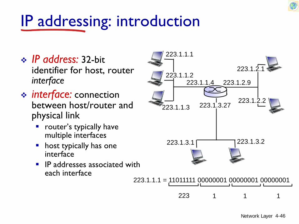
IP addressing: introduction
IP address: 32-bit identifier for host, router interface
interface: connection between host/router and physical link router’s typically have
multiple interfaces host typically has one
interface IP addresses associated with
each interface
Network Layer 4-46
223.1.1.1
223.1.1.2
223.1.1.3
223.1.1.4 223.1.2.9
223.1.2.2
223.1.2.1
223.1.3.2223.1.3.1
223.1.3.27
223.1.1.1 = 11011111 00000001 00000001 00000001
223 1 11

Subnets
IP address:subnet part - high order bitshost part - low order bits
what’s a subnet ?device interfaces with same subnet part of IP addresscan physically reach each other without intervening router
Network Layer 4-47
network consisting of 3 subnets
223.1.1.1
223.1.1.3
223.1.1.4 223.1.2.9
223.1.3.2223.1.3.1
subnet
223.1.1.2
223.1.3.27223.1.2.2
223.1.2.1

Subnets
Network Layer 4-48
recipe to determine the
subnets, detach each interface from its host or router, creating islands of isolated networks
each isolated network is called a subnet
subnet mask: /24
223.1.1.0/24223.1.2.0/24
223.1.3.0/24
223.1.1.1
223.1.1.3
223.1.1.4 223.1.2.9
223.1.3.2223.1.3.1
subnet
223.1.1.2
223.1.3.27223.1.2.2
223.1.2.1

Network Layer 4-49
how many? 223.1.1.1
223.1.1.3
223.1.1.4
223.1.2.2223.1.2.1
223.1.2.6
223.1.3.2223.1.3.1
223.1.3.27
223.1.1.2
223.1.7.0
223.1.7.1223.1.8.0223.1.8.1
223.1.9.1
223.1.9.2
Subnets

(Classical) IP Address Structure
An IP address is broken in two parts Network address Host address
The division between network and host is determined by the size of network
Network Layer 4-50
Network host

IP Addressesgiven notion of “network”, let’s re-examine IP addresses:
Network Layer 4-51
0 network host
10 network host
110 network host
1110 multicast address
A
B
C
D
class1.0.0.0 to127.255.255.255
128.0.0.0 to191.255.255.255
192.0.0.0 to223.255.255.255
224.0.0.0 to239.255.255.255
32 bits
“classful” addressing:

IP Addresses IP Classful Addresses:
Class A addresses begin with 0xxx, or 1 to 126 Class B addresses begin with 10xx, or 128 to 191 Class C addresses begin with 110x, or 192 to 223 Class D addresses begin with 1110, or 224 to 239
• Multicast Class E addresses begin with 1111, or 240 to 254
• Experimental
Network Layer 4-52

Classful Addressing Number of elements in each class
Network Layer 4-53
Class Number of classes
Number of local addresses
A 0xxx 128 16,777,216B 10xx 16,384 65,534C 110x 2,097,152 254

Classful Addressing Classful addressing: inefficient use of address space, address space
exhaustion e.g., class B net allocated enough addresses for 65K
hosts, even if only 2K hosts in that network No longer formally part of IP addressing architecture
Network Layer 4-54

IP addressing: CIDR
CIDR: Classless InterDomain Routing Adopted by IETF in 1993 Network (subnet) portion of address of arbitrary length subnet portion of address of arbitrary length address format: a.b.c.d/x, where x is # bits in network
(subnet) portion of address To support 2000 hosts, a block of 2048 addresses of the form
a.b.c.d/21 assigned• 11 bits needed to store 2048 (211=2048)
In practice the 11 bit rightmost addressing could be further divided (subnetting, more on this later)
Network Layer 4-55
11001000 00010111 00010000 00000000
networkpart
hostpart
200.23.16.0/23

Subnet Mask For routing traffic, subnet mask is used to extract the
network (subnet) portion of an IP address A string of 32 bits Bits corresponding to network (and subnet) part set to
‘1’ (one) Bits corresponding to host part set to ‘0’ Ex:
• Addr = 9 . 2 . 225 . 65/24= 00001001.00000010.11100001.01000001
• Mask = 11111111.11111111.11111111.00000000= 255 . 255 . 255 . 0
Network Layer 4-56

Subnet Mask: How To Use?
Logical AND the mask and the IP address EX:
• Addr = 9 . 2 . 225 . 65/24= 00001001.00000010.11100001.01000001
• Mask = 11111111.11111111.11111111.00000000• N/ADR= 00001001.00000010.11100001.00000000
= 9 . 2 . 225 . 0
Network Layer 4-57

Subnetting To minimize waste in classful addressing, IP
subnetting is used The host bits of a classful address is further
divided into “subnet” bits and “host” bits
Note: Only the classful Host bits should be subnetted Classful Network bits should stay intact
Network Layer 4-58

Subnetting Example Class B 162.150.0.0/16 16 subnets 162.150.xxxx0000.0/20 Mask:
• 11111111.11111111.11110000.00000000• 255 . 255 . 240 . 0
Example network 162.150.128.0/20 162.150.144.0/20
Network Layer 4-59

An IP address is “universally” unique Need for private IP address At home (NAT discussion later) Experiments Private networks
Private IP addresses Class A: 10.0.0.0 - 10.255.255.255 Class B: 172.16.0.0 - 172.31.255.255 Class C: 192.168.0.0 - 192.168.255.255
Note: Private IP addresses are not publically routable.
Network Layer 4-60
Private IP Addresses

Network Layer 4-61
IP addresses: how to get one?
Q: How does a host get IP address?
hard-coded by system admin in a file Windows: control-panel->network->configuration-
>tcp/ip->properties UNIX: /etc/rc.config
DHCP: Dynamic Host Configuration Protocol: dynamically get address from as server “plug-and-play”

DHCP: Dynamic Host Configuration Protocol
goal: allow host to dynamically obtain its IP address from network server when it joins network can renew its lease on address in use allows reuse of addresses (only hold address while
connected/“on”) support for mobile users who want to join network
(more shortly)DHCP overview: host broadcasts “DHCP discover” msg [optional] DHCP server responds with “DHCP offer” msg
[optional] host requests IP address: “DHCP request” msg DHCP server sends address: “DHCP ack” msg
Network Layer 4-62

DHCP client-server scenario
Network Layer 4-63
223.1.1.0/24
223.1.2.0/24
223.1.3.0/24
223.1.1.1
223.1.1.3
223.1.1.4 223.1.2.9
223.1.3.2223.1.3.1
223.1.1.2
223.1.3.27223.1.2.2
223.1.2.1
DHCPserver
arriving DHCPclient needs address in thisnetwork

DHCP client-server scenario
Network Layer 4-64
DHCP server: 223.1.2.5 arrivingclient
DHCP discover
src : 0.0.0.0, 68 dest.: 255.255.255.255,67yiaddr: 0.0.0.0transaction ID: 654
DHCP offersrc: 223.1.2.5, 67 dest: 255.255.255.255, 68yiaddrr: 223.1.2.4transaction ID: 654lifetime: 3600 secs
DHCP requestsrc: 0.0.0.0, 68 dest:: 255.255.255.255, 67yiaddrr: 223.1.2.4transaction ID: 655lifetime: 3600 secs
DHCP ACKsrc: 223.1.2.5, 67 dest: 255.255.255.255, 68yiaddrr: 223.1.2.4transaction ID: 655lifetime: 3600 secs

DHCP: more than IP addressesDHCP can return more than just allocated IP
address on subnet: address of first-hop router for client name and IP address of DNS sever network mask (indicating network versus host portion
of address)
Network Layer 4-65

DHCP: Broadcast or Unicast” DHCPDISCOVER is broadcast over the subnet
attached to the DHCP client (UDP broadcast to 255.255.255.255)
If DHCP server does not reside on that subnet, the gateway need to direct the discover to the remote server (UDP unicast) The gateway router should be configured to do so. Otherwise DHCPDISCOVER fails
Network Layer 4-66

DHCP: Broadcast or Unicast” DHCPDISCOVER is broadcast over the subnet
attached to the DHCP client (UDP broadcast to 255.255.255.255)
If DHCP server does not reside on that subnet, The gateway needs to direct the discover to the
remote server (UDP unicast) The gateway router should be configured to do so. Otherwise DHCPDISCOVER fails
Network Layer 4-67

DHCP: example
Network Layer 4-68
Connecting laptop needs its IP address, addr of first-hop router, addr of DNS server: use DHCP
router with DHCP server built into router
DHCP request encapsulated in UDP, encapsulated in IP, encapsulated in 802.1 Ethernet
Ethernet frame broadcast (dest: FFFFFFFFFFFF) on LAN, received at router running DHCP server
Ethernet demuxed to IP demuxed, UDP demuxed to DHCP
168.1.1.1
DHCPUDP
IPEthPhy
DHCP
DHCP
DHCP
DHCP
DHCP
DHCPUDP
IPEthPhy
DHCP
DHCP
DHCP
DHCPDHCP

DHCP: example
Network Layer 4-69
DHCP server formulates DHCP ACK containing client’s IP address, IP address of first-hop router for client, name & IP address of DNS server
encapsulation of DHCP server, frame forwarded to client, demuxing up to DHCP at client
router with DHCP server built into router
DHCP
DHCP
DHCP
DHCP
DHCPUDP
IPEthPhy
DHCP
DHCPUDP
IPEthPhy
DHCP
DHCP
DHCP
DHCP
client now knows its IP address, name and IP address of DSN server, IP address of its first-hop router

DHCP: Wireshark output (home LAN)
Network Layer 4-70
Message type: Boot Reply (2)Hardware type: EthernetHardware address length: 6Hops: 0Transaction ID: 0x6b3a11b7Seconds elapsed: 0Bootp flags: 0x0000 (Unicast)Client IP address: 192.168.1.101 (192.168.1.101)Your (client) IP address: 0.0.0.0 (0.0.0.0)Next server IP address: 192.168.1.1 (192.168.1.1)Relay agent IP address: 0.0.0.0 (0.0.0.0)Client MAC address: Wistron_23:68:8a (00:16:d3:23:68:8a)Server host name not givenBoot file name not givenMagic cookie: (OK)Option: (t=53,l=1) DHCP Message Type = DHCP ACKOption: (t=54,l=4) Server Identifier = 192.168.1.1Option: (t=1,l=4) Subnet Mask = 255.255.255.0Option: (t=3,l=4) Router = 192.168.1.1Option: (6) Domain Name Server
Length: 12; Value: 445747E2445749F244574092; IP Address: 68.87.71.226;IP Address: 68.87.73.242; IP Address: 68.87.64.146
Option: (t=15,l=20) Domain Name = "hsd1.ma.comcast.net."
reply
Message type: Boot Request (1)Hardware type: EthernetHardware address length: 6Hops: 0Transaction ID: 0x6b3a11b7Seconds elapsed: 0Bootp flags: 0x0000 (Unicast)Client IP address: 0.0.0.0 (0.0.0.0)Your (client) IP address: 0.0.0.0 (0.0.0.0)Next server IP address: 0.0.0.0 (0.0.0.0)Relay agent IP address: 0.0.0.0 (0.0.0.0)Client MAC address: Wistron_23:68:8a (00:16:d3:23:68:8a)Server host name not givenBoot file name not givenMagic cookie: (OK)Option: (t=53,l=1) DHCP Message Type = DHCP RequestOption: (61) Client identifier
Length: 7; Value: 010016D323688A; Hardware type: EthernetClient MAC address: Wistron_23:68:8a (00:16:d3:23:68:8a)
Option: (t=50,l=4) Requested IP Address = 192.168.1.101Option: (t=12,l=5) Host Name = "nomad"Option: (55) Parameter Request List
Length: 11; Value: 010F03062C2E2F1F21F92B1 = Subnet Mask; 15 = Domain Name3 = Router; 6 = Domain Name Server44 = NetBIOS over TCP/IP Name Server……
request

IP addresses: how to get one?Q: how does network get subnet part of IP address?A: gets allocated portion of its provider ISP’s
address space
Network Layer 4-71
ISP's block 10101000 00010111 00010000 00000000 168.23.16.0/20
Organization 0 10101000 00010111 00010000 00000000 168.23.16.0/23 Organization 1 10101000 00010111 00010010 00000000 168.23.18.0/23 Organization 2 10101000 00010111 00010100 00000000 168.23.20.0/23
... ….. …. ….Organization 7 10101000 00010111 00011110 00000000 168.23.30.0/23

Hierarchical addressing: route aggregation
Network Layer 4-72
“Send me anythingwith addresses beginning 168.23.16.0/20”
168.23.16.0/23
168.23.18.0/23
168.23.30.0/23
Fly-By-Night-ISP
Organization 0
Organization 7Internet
Organization 1
ISPs-R-Us “Send me anythingwith addresses beginning 128.31.0.0/16”
168.23.20.0/23Organization 2
...
...
hierarchical addressing allows efficient advertisement of routing information:

Hierarchical addressing: more specific routes
Network Layer 4-73
ISPs-R-Us has a more specific route to Organization 1
“Send me anythingwith addresses beginning 168.23.16.0/20”
168.23.16.0/23
168.23.18.0/23
168.23.30.0/23
Fly-By-Night-ISP
Organization 0
Organization 7Internet
Organization 1
ISPs-R-Us “Send me anythingwith addresses beginning 128.31.0.0/16(255.255.0.0)or 168.23.18.0/23”(255.255.252.0)
168.23.20.0/23Organization 2
...
...
Longest prefix matchingdetermines the route

Hierarchical addressing: Network Addresses and Masks
Network Layer 4-74
168 . 23 . 16 . 0/2311111111.11111111.11111110.00000000
255 . 255 . 254 . 0
Net addressMask (Binary)Mask (Decimal)
168 . 23 . 16 . 0/2011111111.11111111.11110000.00000000
255 . 255 . 240 . 0
Net addressMask (Binary)Mask (Decimal)
128 . 31 . 0 . 0/1611111111.11111111.00000000.00000000
255 . 255 . 0 . 0
Net addressMask (Binary)Mask (Decimal)
168 . 23 . 18 . 0/2311111111.11111111.11111110.00000000
255 . 255 . 254 . 0
Net addressMask (Binary)Mask (Decimal)

IP addressing: the last word...
Q: how does an ISP get block of addresses?A: ICANN: Internet Corporation for Assigned
Names and Numbers http://www.icann.org/ allocates addresses manages DNS assigns domain names, resolves disputes
Network Layer 4-75

NAT: network address translation
Network Layer 4-76
10.0.0.1
10.0.0.2
10.0.0.3
10.0.0.4
138.76.29.7
local network(e.g., home network)
10.0.0/24
rest ofInternet
datagrams with source or destination in this networkhave 10.0.0/24 address for source, destination (as usual)
all datagrams leaving localnetwork have same single
source NAT IP address: 138.76.29.7,different source
port numbers

NAT: network address translationmotivation: local network uses just one IP address as
far as outside world is concerned: range of addresses not needed from ISP: just
one IP address for all devices can change addresses of devices in local
network without notifying outside world can change ISP without changing addresses of
devices in local network devices inside local net not explicitly
addressable, visible by outside world (a security plus)
Network Layer 4-77

NAT: network address translationimplementation: NAT router must:
outgoing datagrams: replace (source IP address, port #) of every outgoing datagram to (NAT IP address, new port #)
. . . remote clients/servers will respond using (NAT IP address, new port #) as destination addr
remember (in NAT translation table) every (source IP address, port #) to (NAT IP address, new port #) translation pair
incoming datagrams: replace (NAT IP address, new port #) in dest fields of every incoming datagram with corresponding (source IP address, port #) stored in NAT table
Network Layer 4-78

NAT: network address translation
Network Layer 4-79
10.0.0.1
10.0.0.2
10.0.0.3
S: 10.0.0.1, 3345D: 128.119.40.186, 80
110.0.0.4
138.76.29.7
1: host 10.0.0.1 sends datagram to 128.119.40.186, 80
NAT translation tableWAN side addr LAN side addr138.76.29.7, 5001 10.0.0.1, 3345…… ……
S: 128.119.40.186, 80 D: 10.0.0.1, 3345 4
S: 138.76.29.7, 5001D: 128.119.40.186, 802
2: NAT routerchanges datagramsource addr from10.0.0.1, 3345 to138.76.29.7, 5001,updates table
S: 128.119.40.186, 80 D: 138.76.29.7, 5001 3
3: reply arrivesdest. address:138.76.29.7, 5001
4: NAT routerchanges datagramdest addr from138.76.29.7, 5001 to 10.0.0.1, 3345

NAT: network address translation 16-bit port-number field: 60,000 simultaneous connections with a single
LAN-side address! NAT is controversial: routers should only process up to layer 3 violates end-to-end argument
• NAT possibility must be taken into account by app designers, e.g., P2P applications
address shortage should instead be solved by IPv6
Network Layer 4-80

NAT traversal problem
client wants to connect to server with address 10.0.0.1 server address 10.0.0.1 local to
LAN (client can’t use it as destination addr)
only one externally visible NATedaddress: 138.76.29.7
solution1: statically configure NAT to forward incoming connection requests at given port to server e.g., (123.76.29.7, port 2500)
always forwarded to 10.0.0.1 port 25000
Network Layer 4-81
10.0.0.1
10.0.0.4
NAT router
138.76.29.7
client
?

NAT traversal problem
solution 2: Universal Plug and Play (UPnP) Internet Gateway Device (IGD) Protocol. Allows NATed host to: learn public IP address (138.76.29.7) add/remove port mappings (with lease
times)
i.e., automate static NAT port map configuration
Network Layer 4-82
10.0.0.1
NAT router
IGD

NAT traversal problem solution 3: relaying (used in Skype) NATed client establishes connection to relay external client connects to relay relay bridges packets between to connections
Network Layer 4-83
138.76.29.7
client
1. connection torelay initiatedby NATed host
2. connection torelay initiatedby client
3. relaying established
NAT router
10.0.0.1

Chapter 4: outline4.1 introduction4.2 virtual circuit and
datagram networks4.3 what’s inside a router4.4 IP: Internet Protocol
datagram format IPv4 addressing ICMP IPv6
4.5 routing algorithms link state distance vector hierarchical routing
4.6 routing in the Internet RIP OSPF BGP
4.7 broadcast and multicast routing
Network Layer 4-84

ICMP: Internet Control Message Protocol
In contrast to a single network, in an internet, no special hardware can assist in reporting and resolving problems. In an internet, software assists in reporting problems
When things go wrong, ICMP comes to help ICMP Allows routers to send error messages or control messages to
other routers/hosts ICMP provides communication between the IP software not
application software All hosts and routers must be able to generate ICMP messages and
process the ICMP messages they receive. An arbitrary machine can send an ICMP message to any other machine.
ICMP is an error reporting mechanism. It does not fully specify the action to be taken for each possible error. ICMP is also used to help identify network problems (e.g. ping)
Network Layer 4-85

ICMP (Cont.)
ICMP reports problems to the original source. It cannot be used to inform intermediate routers about problems.
Why?
Network Layer 4-86
A datagram only contains source and destination address, not the intermediate nodes on a path

ICMP Message Delivery
Network Layer 4-87
ICMP message requires two levels of encapsulation
ICMP utilizes IP, but is considered to be at same level in protocol stack
ICMP messages are carried in IP datagram with ordinary IP headers with the Protocol field set to 1
IP Header
Protocol=1
ICMP Message

Types and Format of Error Messages
ICMP messages originate from a router or a host depending on type of error condition
Network Layer 4-88
ICMP Error MessagesMessage Description
Destination Unreachable
A datagram cannot reach its destination host, utility, or application
Time Exceeded The time-to-Live has expired at a router, or the Fragment Reassembly Time has expired at a destination host.
Parameter Problem There is a bad parameter in the IP header
Source Quench A router or destination is congested. (It is recommended that systems should not send Quench messages)
Redirect A host has routed a datagram to the wrong local router

When Not To Send ICMP
ICMP is used to send error messages when a network is under stress
Care should be taken that the ICMP traffic does not flood the network (making the situation worse!)
ICMP must not report problems caused by Routing or delivering ICMP messages Broadcast or multicast datagrams Datagram fragments other than the first Messages whose source address do not identify a unique host
• E.g., source IP addresses such as 127.0.0.1 or 0.0.0.0
Network Layer 4-89

ICMP Message Format
TYPE: identifies the messageCODE: further information about the
message typeCHECKSUM: only covers the ICMP message
In addition, ICMP messages that report errors always include the header and first 64 data bit of the datagram causing the problem.
Network Layer 4-90

ICMP: internet control message protocol
used by hosts & routers to communicate network-level information error reporting:
unreachable host, network, port, protocol
echo request/reply (used by ping)
network-layer “above” IP: ICMP msgs carried in IP
datagrams ICMP message: type, code
plus first 8 bytes of IP datagram causing error
Type Code description0 0 echo reply (ping)3 0 dest. network unreachable3 1 dest host unreachable3 2 dest protocol unreachable3 3 dest port unreachable3 6 dest network unknown3 7 dest host unknown4 0 source quench (congestion
control - not used)8 0 echo request (ping)9 0 route advertisement10 0 router discovery11 0 TTL expired12 0 bad IP header
Network Layer 4-91

traceroute and ICMP source sends series of
UDP segments to dest first set has TTL =1 second set has TTL=2, etc. unlikely port number
when nth set of datagrams arrives to nth router: router discards datagrams and sends source ICMP
messages (type 11, code 0) ICMP messages includes
name of router & IP address
when ICMP messages arrives, source records RTTs
stopping criteria: UDP segment eventually
arrives at destination host destination returns ICMP
“port unreachable” message (type 3, code 3)
source stops
Network Layer 4-92
3 probes
3 probes
3 probes

ICMP Example: Echo Request/Reply
Used by processors to test whether a destination is alive and reachable Example: ping
TYPE=8 (Request) or 0 (Reply) IDENTIFER/SEQUENCE
NUMBER: used by sender to match replies to request
DATA: Optional further matching information (returned by the sender)
Network Layer 4-93

ICMP Example: Destination Unreachable
Network Layer 4-94
Sent by a router to the source when it cannot forward or deliver an IP datagram
Code

ICMP Example: Redirect (Change Route)
Used by router to notify host to change its routing table There are more than one
routers on the network The host sends a datagram to
a wrong router (resulting in a longer route)
The router however forwards the datagram to the correct router and notifies the host
The host should send the subsequent traffic to the shorter route.
Network Layer 4-95
ICMP Redirect can be used to reduce manual network administration Hosts always use a default
router The default router redirects
the requests to optimal routers
Hosts update their tables dynamically

ICMP Example: Redirect (Cont.)
Network Layer 4-96
Format
Code
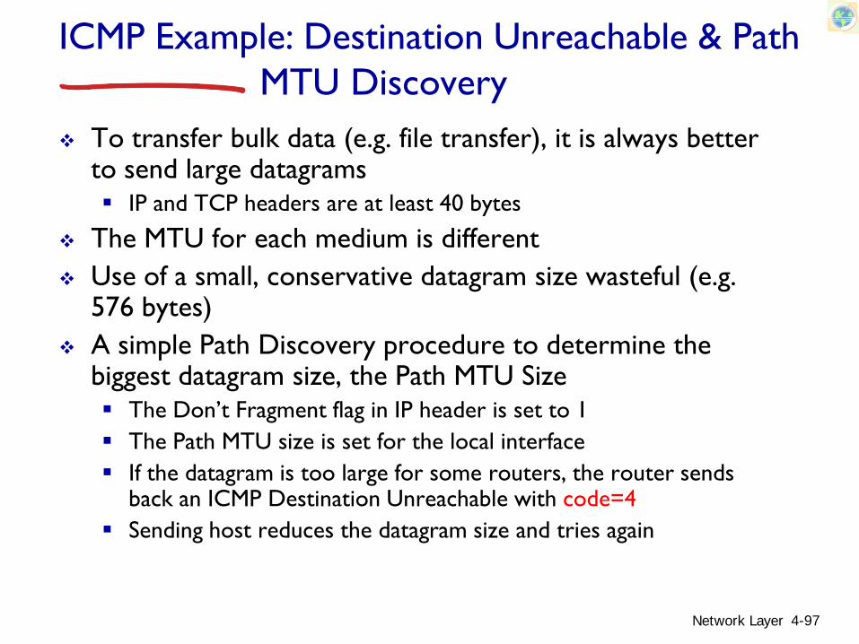
ICMP Example: Destination Unreachable & PathMTU Discovery
To transfer bulk data (e.g. file transfer), it is always better to send large datagrams IP and TCP headers are at least 40 bytes
The MTU for each medium is different Use of a small, conservative datagram size wasteful (e.g.
576 bytes) A simple Path Discovery procedure to determine the
biggest datagram size, the Path MTU Size The Don’t Fragment flag in IP header is set to 1 The Path MTU size is set for the local interface If the datagram is too large for some routers, the router sends
back an ICMP Destination Unreachable with code=4 Sending host reduces the datagram size and tries again
Network Layer 4-97

Viewing ICMP Activities
Use command “netstat -s” to view network activities Example: on Windows NT
C>netstat -s
IP Statistics
Packets Received = 21111
Received Header Errors = 194
Received Address Errors = 1063
Datagrams Forwarded = 0
Unknown Protocols Received = 0
Received Packets Discarded = 0
Received Packets Delivered = 20208
Output Requests = 11559
Routing Discards = 0
Discarded Output Packets = 0
Output Packet No Route = 0
Reassembly Required = 0
Reassembly Successful = 0
Reassembly Failures = 0
Datagrams Successfully Fragmented = 0
Datagrams Failing Fragmentation = 0
Fragments Created = 0
Network Layer 4-98

Viewing ICMP Activities (Cont.)
Example: Cont.ICMP Statistics
Received Sent
Messages 23 23
Errors 0 0
Destination Unreachable 0 0
Time Exceeded 0 0
Parameter Problems 0 0
Source Quenchs 0 0
Redirects 0 0
Echos 0 23
Echo Replies 23 0
Timestamps 0 0
Timestamp Replies 0 0
Address Masks 0 0
Address Mask Replies 0 0
Network Layer 4-99

Chapter 4: outline4.1 introduction4.2 virtual circuit and
datagram networks4.3 what’s inside a router4.4 IP: Internet Protocol
datagram format IPv4 addressing ICMP IPv6
4.5 routing algorithms link state distance vector hierarchical routing
4.6 routing in the Internet RIP OSPF BGP
4.7 broadcast and multicast routing
Network Layer 4-100
IPv6: motivation initial motivation: 32-bit address space soon to be
completely allocated. additional motivation: header format helps speed processing/forwarding header changes to facilitate QoS
IPv6 datagram format: fixed-length 40 byte header no fragmentation allowed
Network Layer 4-101

IPv6 datagram format
Network Layer 4-102
priority: identify priority among datagrams in flowflow Label: identify datagrams in same “flow.”
(concept of “flow” not well defined).next header: identify upper layer protocol for data
data
destination address(128 bits)
source address(128 bits)
payload len next hdr hop limitflow labelpriver
32 bits

Other changes from IPv4 checksum: removed entirely to reduce processing
time at each hop options: allowed, but outside of header, indicated
by “Next Header” field ICMPv6: new version of ICMP additional message types, e.g. “Packet Too Big” multicast group management functions
Network Layer 4-103

Transition from IPv4 to IPv6 not all routers can be upgraded simultaneously no “flag days” how will network operate with mixed IPv4 and
IPv6 routers? tunneling: IPv6 datagram carried as payload in IPv4
datagram among IPv4 routers
Network Layer 4-104
IPv4 source, dest addr IPv4 header fields
IPv4 datagramIPv6 datagram
IPv4 payload
UDP/TCP payloadIPv6 source dest addr
IPv6 header fields

Tunneling
Network Layer 4-105
physical view:IPv4 IPv4
A B
IPv6 IPv6
E
IPv6 IPv6
FC D
logical view:
IPv4 tunnel connecting IPv6 routers E
IPv6 IPv6
FA B
IPv6 IPv6

Tunneling
Network Layer 4-106
flow: Xsrc: Adest: F
data
A-to-B:IPv6
Flow: XSrc: ADest: F
data
src:Bdest: E
B-to-C:IPv6 inside
IPv4
E-to-F:IPv6
flow: Xsrc: Adest: F
data
B-to-C:IPv6 inside
IPv4
Flow: XSrc: ADest: F
data
src:Bdest: E
physical view:A B
IPv6 IPv6
E
IPv6 IPv6
FC D
logical view:
IPv4 tunnel connecting IPv6 routers E
IPv6 IPv6
FA B
IPv6 IPv6
IPv4 IPv4

Chapter 4: outline4.1 introduction4.2 virtual circuit and
datagram networks4.3 what’s inside a router4.4 IP: Internet Protocol
datagram format IPv4 addressing ICMP IPv6
4.5 routing algorithms link state distance vector hierarchical routing
4.6 routing in the Internet RIP OSPF BGP
4.7 broadcast and multicast routing
Network Layer 4-107

Interplay between routing, forwarding
Network Layer 4-108
1
23
IP destination address in arriving packet’s header
routing algorithm
local forwarding tabledest address output link
address-range 1address-range 2address-range 3address-range 4
3221
routing algorithm determinesend-end-path through network
forwarding table determineslocal forwarding at this router

Host Routing TableIntranet (Direct) Routing: Source and destination on the
same (sub)network (LAN) From: 130.15.12.131/24 To: 130.15.12.22/24 Subnet mask: 255.255.255.0
The source and destination addresses are ANDed with the Mask to extract the networkand subnet portion:
130.15.12.0 Both on the same subnet
Network Layer 4-109
The datagram must be wrappedin a frame and transmitted directly to its destination on the same LAN
The ARP table is checked to provide the physical address for the destination IP address If not there, ARP protocol is
used to create one

Datagram Encapsulation: Ethernet
Ethernet frame for the previous example
Network Layer 4-110
LinkHdr
IPHdr
Dest IP=130.15.12.22
Dest Enet= Enet address of 130.15.12.22

Datagram Encapsulation: Ethernet
Network Layer 4-111
IEEE 802.2/802.3 (RFC 1042) and Ethernet (RFC 894) Encapsulations

Getting a datagram from source to destination
Network Layer 4-112
IP datagram:
223.1.1.1
223.1.1.2
223.1.1.3
223.1.1.4 223.1.2.9
223.1.2.2
223.1.2.1
223.1.3.2223.1.3.1
223.1.3.27
A
BE
miscfields
sourceIP addr
destIP addr data
datagram remains unchanged, as it travels source to destination
addr fields of interest here
Dest. Net. next router Nhops
223.1.1 1223.1.2 223.1.1.4 2223.1.3 223.1.1.4 2
forwarding table in AMask=255.255.255.0

Getting a datagram from source to dest.
Network Layer 4-113
Starting at A, send IP datagram addressed to B:look up net. address of B in forwarding tablefind B is on same net. as Alink layer will send datagram directly to B inside link-layer frame
B and A are directly connected
Dest. Net. next router Nhops
223.1.1 1223.1.2 223.1.1.4 2223.1.3 223.1.1.4 2
miscfields 223.1.1.1 223.1.1.3 data
223.1.1.1
223.1.1.2
223.1.1.3
223.1.1.4 223.1.2.9
223.1.2.2
223.1.2.1
223.1.3.2223.1.3.1
223.1.3.27
A
BE
forwarding table in AMask=255.255.255.0

Getting a datagram from source to dest.
Network Layer 4-114
Starting at A, send IP datagram addressed to E:look up net. address of E in forwarding tablefind E is not on same net. as AThe datagram is forwarded to the next router 223.1.1.4
Dest. Net. next router Nhops
223.1.1 1223.1.2 223.1.1.4 2223.1.3 223.1.1.4 2
miscfields 223.1.1.1 223.1.2.2 data
223.1.1.1
223.1.1.2
223.1.1.3
223.1.1.4 223.1.2.9
223.1.2.2
223.1.2.1
223.1.3.2223.1.3.1
223.1.3.27
A
BE
forwarding table in AMask=255.255.255.0

Host Routing Table
Internet (non-direct) routing From: 130.15.12.131 To: 192.45.89.5 Subnet mask: 255.255.255.0
Destination is not on the same LAN (network) Consult the routing table
If a destination is not on the local network, the only way to leave the local net is via a (the) router
Each host contains a routing table to route datagrams to “foreign” hosts
Network Layer 4-115
The default entry always points to a router: Forward any non-local
datagrams to the default router Destination address 0.0.0.0 is
used to mean default in routing tables
Destination is not on the same LAN (network)

Host Routing Table
Network Layer 4-116
Example of two routers on a LAN Interface 128.121.54.2 leads
to a small LAN A look at the routing
table at host “tigger”

Host Routing Table
First destination 127.0.01 is the loopback address For clients/servers within the same node
The default used for any destination not explicitly listed Datagrams to any systems on subnet 128.121.54.0 should be
forwarded to router 128.121.50.2 The last entry declares any destination on subnet 128.121.50.0 is
routed via 128.121.50.145, the node itself Flags indicate whether the route is up (U) and whether the next hop
is a host (H) or a gateway (G)
Network Layer 4-117

Rules for Routing Table Lookups
The routing table entry can be An individual host A subnet A network A supernet Default
General rule: The entry chosen should be based on the most precisematch to the destination IP address First search for a complete IP address match If not, search for destination subnet match If not, search for destination network match If not, search for a routing prefix entry match If not, the default route is used
Network Layer 4-118

Routing Example: Non-direct
Network Layer 4-119
From: bsdi (140.252.13.35) To: ftp.uu.net (192.48.96.9) Subnet mask: 255.255.255.0

Getting a datagram from source to dest.
Network Layer 4-120
Dest. Net. next router Nhops
223.1.1 1223.1.2 223.1.1.4 2223.1.3 223.1.1.4 2Starting at A, dest. E:
look up network address of E in forwarding tableE on different network
A, E not directly attachedrouting table: next hop router to E is 223.1.1.4 link layer sends datagram to router 223.1.1.4 inside link-layer framedatagram arrives at 223.1.1.4 continued…..
miscfields 223.1.1.1 223.1.2.2 data
223.1.1.1
223.1.1.2
223.1.1.3
223.1.1.4 223.1.2.9
223.1.2.2
223.1.2.1
223.1.3.2223.1.3.1
223.1.3.27
A
BE
forwarding table in A

Getting a datagram from source to dest.
Network Layer 4-121
Arriving at 223.1.4, destined for 223.1.2.2look up network address of E in router’s forwarding tableE on same network as router’s interface 223.1.2.9
router, E directly attachedlink layer sends datagram to 223.1.2.2 inside link-layer frame via interface 223.1.2.9datagram arrives at 223.1.2.2!!!(hooray!)
miscfields 223.1.1.1 223.1.2.2 data Dest. Net router Nhops interface
223.1.1 - 1 223.1.1.4223.1.2 - 1 223.1.2.9223.1.3 - 1 223.1.3.27
223.1.1.1
223.1.1.2
223.1.1.3
223.1.1.4 223.1.2.9
223.1.2.2
223.1.2.1
223.1.3.2223.1.3.1
223.1.3.27
A
BE
forwarding table in router

Routing Algorithms
Network Layer 4-122
Graph abstraction for routing algorithms:
graph nodes are routers graph edges are physical
links link cost: delay, $ cost, or
congestion level
Goal: determine “good” path(sequence of routers) through network from source to dest.
Routing Algorithm
A
ED
CB
F2
21
3
1
1
2
53
5
“good” path:typically means minimum cost pathother def’s possible

Graph abstraction
Network Layer 4-123
u
yx
wv
z2
21
3
1
1
2
53
5
graph: G = (N,E)
N = set of routers = { u, v, w, x, y, z }
E = set of links ={ (u,v), (u,x), (v,x), (v,w), (x,w), (x,y), (w,y), (w,z), (y,z) }
aside: graph abstraction is useful in other network contexts, e.g., P2P, where N is set of peers and E is set of TCP connections

Graph abstraction: costs
Network Layer 4-124
u
yx
wv
z2
21
3
1
1
2
53
5 c(x,x’) = cost of link (x,x’)e.g., c(w,z) = 5
cost could always be 1, or inversely related to bandwidth,or inversely related to congestion
cost of path (x1, x2, x3,…, xp) = c(x1,x2) + c(x2,x3) + … + c(xp-1,xp)
key question: what is the least-cost path between u and z ?routing algorithm: algorithm that finds that least cost path

Routing Algorithm and internet: Graph Construction
Need to have graph abstraction of an internet General rule: All nodes in a subnet are fully connected Only routers are important Internet only worries about routing between routers
(and not within subnets) Procedure: Ignore all non-router hosts Remove all connections (links) Fully connect all routers on the same subnet
Network Layer 4-125

Graph abstraction of an internet
Network Layer 4-126
Non-router host
Router

Graph abstraction of an internet
Network Layer 4-127
Non-router host
Router
Step 1: ignore non-router hosts

Graph abstraction of an internet
Network Layer 4-128
Non-router host
Router
Step 2: remove all connections

Graph abstraction of an internet
Network Layer 4-129
Non-router host
Router
Step 3: fully connect all routers within the same subnet

Graph abstraction of an internet
Network Layer 4-130
Non-router host
Router
Step 4: Assign “weight” to links of the graph
Note: All links in a (sub)net have the same weight

Routing algorithm classificationQ: global or decentralized
information?global: all routers have complete
topology, link cost info “link state” algorithmsdecentralized: router knows physically-
connected neighbors, link costs to neighbors
iterative process of computation, exchange of info with neighbors
“distance vector” algorithms
Q: static or dynamic?static: routes change slowly over
timedynamic: routes change more
quickly periodic update in response to link
cost changes
Network Layer 4-131
Chapter 4: outline

Link State & Distance Vector Algorithms
Link State (LS) Each node reports the state/cost of its neighboring
links to all nodes in the network
Distance Vector (DV) Each node reports its distance to all nodes in the
network to its neighboring nodes
Network Layer 4-132

Chapter 4: outline4.1 introduction4.2 virtual circuit and
datagram networks4.3 what’s inside a router4.4 IP: Internet Protocol
datagram format IPv4 addressing ICMP IPv6
4.5 routing algorithms link state distance vector hierarchical routing
4.6 routing in the Internet RIP OSPF BGP
4.7 broadcast and multicast routing
Network Layer 4-133

A Link-State Routing Algorithm
Dijkstra’s algorithm net topology, link costs
known to all nodes accomplished via “link state
broadcast” all nodes have same info
computes least cost paths from one node (‘source”) to all other nodes gives forwarding table for
that node iterative: after k
iterations, know least cost path to k dest.’s
notation: c(x,y): link cost from
node x to y; = ∞ if not direct neighbors
D(v): current value of cost of path from source to dest. v
p(v): predecessor node along path from source to v
N': set of nodes whose least cost path definitively known
Network Layer 4-134

Dijsktra’s Algorithm
Network Layer 4-135
1 Initialization:2 N' = {u} 3 for all nodes v 4 if v adjacent to u 5 then D(v) = c(u,v) 6 else D(v) = ∞7 8 Loop9 find w not in N' such that D(w) is a minimum 10 add w to N'11 update D(v) for all v adjacent to w and not in N' : 12 D(v) = min( D(v), D(w) + c(w,v) ) 13 /* new cost to v is either old cost to v or known 14 shortest path cost to w plus cost from w to v */ 15 until all nodes in N'

Dijkstra's Algorithm: Alternate Method
Label a node v by (D(v),p(v)) Initially, label of the source, A, is (0,-)
Network Layer 4-136
(0,-)
(2,A)(5,A)
(1,A)
( ,-)∞
( ,-)∞

Dijkstra's Algorithm: Alternate Method
Network Layer 4-137
(0,-)
(2,A) (5,A)
(1,A) ( ,-)∞
( ,-)∞
(2,D)
(4,D)
(0,-)
(2,A) (5,A)
(1,A) ( ,-)∞
( ,-)∞
(2,D)
(4,D)
(0,-)
(2,A) (5,A)
(1,A) ( ,-)∞
( ,-)∞
(2,D)
(4,D) (3,E)
(4,E)(0,-)
(2,A) (5,A)
(1,A) ( ,-)∞
( ,-)∞
(2,D)
(4,D) (3,E)
(4,E)

Dijkstra's Algorithm: Alternate Method
Network Layer 4-138
(0,-)
(2,A)
(1,A) (2,D)
(3,E)
(4,E)(0,-)
(2,A) (5,A)
(1,A) ( ,-)∞
( ,-)∞
(2,D)
(4,D) (3,E)
(4,E)

Dijsktra’s Algorithm
Network Layer 4-139
1 Initialization:2 N' = {u} 3 for all nodes v 4 if v adjacent to u 5 then D(v) = c(u,v) 6 else D(v) = ∞7 8 Loop9 find w not in N' such that D(w) is a minimum 10 add w to N'11 update D(v) for all v adjacent to w and not in N' : 12 D(v) = min( D(v), D(w) + c(w,v) ) 13 /* new cost to v is either old cost to v or known 14 shortest path cost to w plus cost from w to v */ 15 until all nodes in N'

Network Layer 4-140
w3
4
v
x
u
5
37 4
y8
z2
7
9
Dijkstra’s algorithm: example
Step N'D(v)
p(v)012345
D(w)p(w)
D(x)p(x)
D(y)p(y)
D(z)p(z)
u ∞ ∞ 7,u 3,u 5,uuw ∞ 11,w6,w 5,u
14,x 11,w 6,wuwxuwxv 14,x 10,v
uwxvy 12,y
notes: construct shortest path tree by
tracing predecessor nodes ties can exist (can be broken
arbitrarily)
uwxvyz
Network Layer 4-141
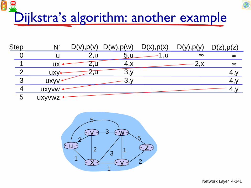
Dijkstra’s algorithm: another example
Step012345
N'u
uxuxy
uxyvuxyvw
uxyvwz
D(v),p(v)2,u2,u2,u
D(w),p(w)5,u4,x3,y3,y
D(x),p(x)1,u
D(y),p(y)∞
2,x
D(z),p(z)∞ ∞
4,y4,y4,y
u
yx
wv
z2
21
3
1
1
2
53
5

Shortest Path Tree
Network Layer 4-142
Shortest path tree rooted at node A
Note: Shortest Path Tree is Dependent on the “root”
Shortest path tree rooted at node B

Shortest Path Tree & Routing Table
Network Layer 4-143
Shortest path tree rooted at node a F
ED
CB
A
Dest. Next NodeA -B BC DD DE DF D
Routing table at node A

Dijkstra’s algorithm: example (2)
Network Layer 4-144
u
yx
wv
z
resulting shortest-path tree from u:
vxywz
(u,v)(u,x)
(u,x)(u,x)(u,x)
destination link
resulting forwarding table in u:

Dijkstra’s algorithm, discussion
algorithm complexity: n nodes each iteration: need to check all nodes, w, not in N n(n+1)/2 comparisons: O(n2) more efficient implementations possible: O(nlogn)
oscillations possible: e.g., support link cost equals amount of carried traffic:
Network Layer 4-145
AD
C
B1 1+e
e0
e
1 1
0 0
initially
AD
C
B
given these costs,find new routing….
resulting in new costs
2+e 0
001+e 1
AD
C
B
given these costs,find new routing….
resulting in new costs
0 2+e
1+e10 0
AD
C
B
given these costs,find new routing….
resulting in new costs
2+e 0
001+e 1

Some cures to Dijkstra’s Algorithm
Mandate link cost not depend on traffic Not acceptable
Ensure all routers do not run the algorithm at the same time
Observation: Routers in network self synchronize their operation Enforce a randomization
Network Layer 4-146

Chapter 4: outline4.1 introduction4.2 virtual circuit and
datagram networks4.3 what’s inside a router4.4 IP: Internet Protocol
datagram format IPv4 addressing ICMP IPv6
4.5 routing algorithms link state distance vector hierarchical routing
4.6 routing in the Internet RIP OSPF BGP
4.7 broadcast and multicast routing
Network Layer 4-147

Distance Vector Routing Principle
Network Layer 4-148
The shortest distance from a node to a destination via a given neighbor is the shortest distance from the neighbor to the destination plus the distance from the node to that neighbor

Distance vector algorithm
Network Layer 4-149
Bellman-Ford equation (dynamic programming)
letdx(y) := cost of least-cost path from x to y
thendx(y) = min {c(x,v) + dv(y) }
v
cost to neighbor v
min taken over all neighbors v of x
cost from neighbor v to destination y

Bellman-Ford example
Network Layer 4-150
u
yx
wv
z2
21
3
1
1
2
53
5clearly, dv(z) = 5, dx(z) = 3, dw(z) = 3
du(z) = min { c(u,v) + dv(z),c(u,x) + dx(z),c(u,w) + dw(z) }
= min {2 + 5,1 + 3,5 + 3} = 4
node achieving minimum is nexthop in shortest path, used in forwarding table
B-F equation says:

Distance vector algorithm Dx(y) = estimate of least cost from x to y x maintains distance vector Dx = [Dx(y): y є N ]
node x: knows cost to each neighbor v: c(x,v) maintains its neighbors’ distance vectors. For
each neighbor v, x maintains Dv = [Dv(y): y є N ]
Network Layer 4-151

Distance vector algorithm key idea: from time-to-time, each node sends its own
distance vector estimate to neighbors when x receives new DV estimate from neighbor,
it updates its own DV using B-F equation:
Dx(y) ← minv{c(x,v) + Dv(y)} for each node y ∊ N
under minor, natural conditions, the estimate Dx(y) converge to the actual least cost dx(y)
Network Layer 4-152

Distance vector algorithm iterative, asynchronous:
each local iteration caused by:
local link cost change DV update message from
neighbordistributed: each node notifies
neighbors only when its DV changes neighbors then notify their
neighbors if necessary
each node:
Network Layer 4-153
wait for (change in local link cost or msg from neighbor)
recompute estimates
if DV to any dest has changed, notify neighbors

Distance Table: example
Network Layer 4-154
A
E D
CB7
81
2
1
2 D ()
A
B
C
D
A
1
7
6
4
B
14
8
9
11
D
5
5
4
2
Ecost to destination via
D (C,D)Ec(E,D) + min {D (C,w)}D
w== 2+2 = 4
D (A,D)Ec(E,D) + min {D (A,w)}D
w== 2+3 = 5 loop!
D (A,B)Ec(E,B) + min {D (A,w)}B
w== 8+6 = 14
loop!
D (Y,Z)Xdistance from X toY, via Z as next hop
c(X,Z) + min {D (Y,w)}Zw
=
=

Network Layer 4-155
x y z
xyz
0 2 7
∞ ∞ ∞∞ ∞ ∞
from
cost to
from
from
x y z
xyz
0
x y z
xyz
∞ ∞
∞ ∞ ∞
cost to
x y z
xyz
∞ ∞ ∞7 1 0
cost to
∞2 0 1
∞ ∞ ∞
2 0 17 1 0
time
x z12
7
y
node xtable
Dx(y) = min{c(x,y) + Dy(y), c(x,z) + Dz(y)}= min{2+0 , 7+1} = 2
Dx(z) = min{c(x,y) +Dy(z), c(x,z) + Dz(z)}
= min{2+1 , 7+0} = 3
32
node ytable
node ztable
cost to
from

Network Layer 4-156
x y z
xyz
0 2 3
from
cost to
x y z
xyz
0 2 7
from
cost tox y z
xyz
0 2 3
from
cost to
x y z
xyz
0 2 3fro
mcost to
x y z
xyz
0 2 7
from
cost to
2 0 17 1 0
2 0 13 1 0
2 0 13 1 0
2 0 1
3 1 0
2 0 1
3 1 0
time
x y z
xyz
0 2 7
∞ ∞ ∞∞ ∞ ∞
from
cost to
from
from
x y z
xyz
0
x y z
xyz
∞ ∞
∞ ∞ ∞
cost to
x y z
xyz
∞ ∞ ∞7 1 0
cost to
∞2 0 1
∞ ∞ ∞
2 0 17 1 0
time
x z12
7
y
node xtable
Dx(y) = min{c(x,y) + Dy(y), c(x,z) + Dz(y)}= min{2+0 , 7+1} = 2
Dx(z) = min{c(x,y) +Dy(z), c(x,z) + Dz(z)}
= min{2+1 , 7+0} = 3
32
node ytable
node ztable
cost to
from

Distance vector: link cost changes
Network Layer 4-157
link cost changes: node detects local link cost change updates routing info, recalculates
distance vector if DV changes, notify neighbors
“goodnews travelsfast”
x z14
50
y1
t0 : y detects link-cost change, updates its DV, informs its neighbors.
t1 : z receives update from y, updates its table, computes new least cost to x , sends its neighbors its DV.
t2 : y receives z’s update, updates its distance table. y’s least costs do not change, so y does not send a message to z.

Distance vector: link cost changes
Network Layer 4-158
link cost changes: node detects local link cost change updates routing info, recalculates
distance vector if DV changes, notify neighbors
“goodnews travelsfast”
x z14
50
y1
algorithmterminates

Distance Vector: link cost changes
Network Layer 4-159
Link cost changes:good news travels fast bad news travels slow - “count to infinity” problem! X Z
14
50
Y60
algorithmcontinues
on!

Distance Vector: poisoned reverse
Network Layer 4-160
If Z routes through Y to get to X :Z tells Y its (Z’s) distance to X is infinite (so Y won’t route to X via Z)will this completely solve count to infinity problem?
X Z14
50
Y60
algorithmterminates

Distance vector: link cost changes
Network Layer 4-161
link cost changes: node detects local link cost change bad news travels slow - “count to
infinity” problem! 44 iterations before algorithm
stabilizes: see text
x z14
50
y60
poisoned reverse: If Z routes through Y to get to X :
Z tells Y its (Z’s) distance to X is infinite (so Y won’t route to X via Z)
will this completely solve count to infinity problem?

Comparison of LS and DV algorithms
message complexity LS: with n nodes, E links, O(nE)
msgs sent DV: exchange between
neighbors only convergence time varies
speed of convergence LS: O(n2) algorithm requires
O(nE) msgs may have oscillations
DV: convergence time varies may be routing loops count-to-infinity problem
robustness: what happens if router malfunctions?
LS: node can advertise
incorrect link cost each node computes only
its own tableDV:
DV node can advertise incorrect path cost
each node’s table used by others
• error propagate thru network
Network Layer 4-162

Chapter 4: outline4.1 introduction4.2 virtual circuit and
datagram networks4.3 what’s inside a router4.4 IP: Internet Protocol
datagram format IPv4 addressing ICMP IPv6
4.5 routing algorithms link state distance vector hierarchical routing
4.6 routing in the Internet RIP OSPF BGP
4.7 broadcast and multicast routing
Network Layer 4-163

Hierarchical routing
scale: with 600 million destinations:
can’t store all dest’s in routing tables!
routing table exchange would swamp links!
administrative autonomy internet = network of
networks each network admin may
want to control routing in its own network
Network Layer 4-164
our routing study thus far - idealization all routers identical network “flat”… not true in practice

Hierarchical routing aggregate routers into
regions, “autonomous systems” (AS)
routers in same AS run same routing protocol “intra-AS” routing
protocol routers in different AS
can run different intra-AS routing protocol
gateway router: at “edge” of its own AS has link to router in
another AS
Network Layer 4-165

Interconnected ASes
Network Layer 4-166
forwarding table configured by both intra-and inter-AS routing algorithm intra-AS sets entries
for internal dests inter-AS & intra-AS
sets entries for external dests
3b
1d
3a
1c2aAS3
AS1AS2
1a
2c2b
1b
Intra-ASRouting algorithm
Inter-ASRouting algorithm
Forwardingtable
3c

Inter-AS tasks suppose router in AS1
receives datagram destined outside of AS1: router should forward
packet to gateway router, but which one?
AS1 must:1. learn which dests are
reachable through AS2, which through AS3
2. propagate this reachability info to all routers in AS1
job of inter-AS routing!
Network Layer 4-167
AS3
AS2
3b
3c3a
AS1
1c1a
1d1b
2a2c
2bothernetworks
othernetworks

Example: setting forwarding table in router 1d
suppose AS1 learns (via inter-AS protocol) that subnet xreachable via AS3 (gateway 1c), but not via AS2 inter-AS protocol propagates reachability info to all
internal routers router 1d determines from intra-AS routing info that its
interface I is on the least cost path to 1c installs forwarding table entry (x,I)
Network Layer 4-168
AS3
AS2
3b
3c3a
AS1
1c1a
1d1b
2a2c
2bothernetworks
othernetworks
x

Example: choosing among multiple ASes
now suppose AS1 learns from inter-AS protocol that subnet x is reachable from AS3 and from AS2.
to configure forwarding table, router 1d must determine which gateway it should forward packets towards for destx this is also job of inter-AS routing protocol!
Network Layer 4-169
AS3
AS2
3b
3c3a
AS1
1c1a
1d1b
2a2c
2bothernetworks
othernetworks
x
?

Example: choosing among multiple ASes
now suppose AS1 learns from inter-AS protocol that subnet x is reachable from AS3 and from AS2.
to configure forwarding table, router 1d must determine towards which gateway it should forward packets for dest x this is also job of inter-AS routing protocol!
hot potato routing: send packet towards closest of two routers.
Network Layer 4-170
learn from inter-AS protocol that subnet x is reachable via multiple gateways
use routing infofrom intra-AS
protocol to determinecosts of least-cost
paths to eachof the gateways
hot potato routing:choose the gateway
that has the smallest least cost
determine fromforwarding table the interface I that leads
to least-cost gateway. Enter (x,I) in
forwarding table

Chapter 4: outline4.1 introduction4.2 virtual circuit and
datagram networks4.3 what’s inside a router4.4 IP: Internet Protocol
datagram format IPv4 addressing ICMP IPv6
4.5 routing algorithms link state distance vector hierarchical routing
4.6 routing in the Internet RIP OSPF BGP
4.7 broadcast and multicast routing
Network Layer 4-171
Intra-AS Routing
also known as interior gateway protocols (IGP) most common intra-AS routing protocols: RIP: Routing Information Protocol OSPF: Open Shortest Path First IGRP: Interior Gateway Routing Protocol
(Cisco proprietary)
Network Layer 4-172

RIP ( Routing Information Protocol) included in BSD-UNIX distribution in 1982 distance vector algorithm
distance metric: # hops (max = 15 hops), each link has cost 1 DVs exchanged with neighbors every 30 sec in response message
(aka advertisement) each advertisement: list of up to 25 destination subnets (in IP
addressing sense)
Network Layer 4-173
DC
BAu v
w
x
yz
subnet hopsu 1v 2w 2x 3y 3z 2
from router A to destination subnets:

RIP: example
Network Layer 4-174
destination subnet next router # hops to destw A 2y B 2z B 7x -- 1…. …. ....
routing table in router D
w x yz
A
C
D B

RIP: example
Network Layer 4-175
w x yz
A
C
D B
destination subnet next router # hops to destw A 2y B 2z B 7x -- 1…. …. ....
routing table in router D
A 5
dest next hopsw - 1x - 1z C 4…. … ...
A-to-D advertisement

RIP: link failure, recovery
if no advertisement heard after 180 sec --> neighbor/link declared dead routes via neighbor invalidated new advertisements sent to neighbors neighbors in turn send out new advertisements (if
tables changed) link failure info quickly (?) propagates to entire net poison reverse used to prevent ping-pong loops (infinite
distance = 16 hops)
Network Layer 4-176

RIP table processing
RIP routing tables managed by application-levelprocess called route-d (daemon)
advertisements sent in UDP packets, periodically repeated
Network Layer 4-177
physicallink
network forwarding(IP) table
transport(UDP)
routed
physicallink
network(IP)
transprt(UDP)
routed
forwardingtable

OSPF (Open Shortest Path First)
“open”: publicly available uses link state algorithm LS packet dissemination topology map at each node route computation using Dijkstra’s algorithm
OSPF advertisement carries one entry per neighbor
advertisements flooded to entire AS carried in OSPF messages directly over IP (rather than
TCP or UDP IS-IS routing protocol: nearly identical to OSPF
Network Layer 4-178

OSPF “advanced” features (not in RIP)
security: all OSPF messages authenticated (to prevent malicious intrusion)
multiple same-cost paths allowed (only one path in RIP)
for each link, multiple cost metrics for different TOS (e.g., satellite link cost set “low” for best effort ToS; high for real time ToS)
integrated uni- and multicast support: Multicast OSPF (MOSPF) uses same topology
data base as OSPF hierarchical OSPF in large domains.
Network Layer 4-179

Hierarchical OSPF
Network Layer 4-180
boundary router
backbone router
area 1area 2
area 3
backboneareaborderrouters
internalrouters

Hierarchical OSPF two-level hierarchy: local area, backbone. link-state advertisements only in area each nodes has detailed area topology; only
know direction (shortest path) to nets in other areas.
area border routers: “summarize” distances to nets in own area, advertise to other Area Border routers.
backbone routers: run OSPF routing limited to backbone.
boundary routers: connect to other AS’s.
Network Layer 4-181

Internet inter-AS routing: BGP
BGP (Border Gateway Protocol): the de facto inter-domain routing protocol “glue that holds the Internet together”
BGP provides each AS a means to: eBGP: obtain subnet reachability information from
neighboring ASs. iBGP: propagate reachability information to all AS-
internal routers. determine “good” routes to other networks based on
reachability information and policy. allows subnet to advertise its existence to rest of
Internet: “I am here”
Network Layer 4-182

BGP basics BGP session: two BGP routers (“peers”) exchange BGP
messages: advertising paths to different destination network prefixes (“path
vector” protocol) exchanged over semi-permanent TCP connections
when AS3 advertises a prefix to AS1: AS3 promises it will forward datagrams towards that prefix AS3 can aggregate prefixes in its advertisement
Network Layer 4-183
AS3
AS2
3b
3c3a
AS1
1c1a
1d1b
2a2c
2bothernetworks
othernetworks
BGP message

BGP basics: distributing path information
using eBGP session between 3a and 1c, AS3 sends prefix reachability info to AS1. 1c can then use iBGP do distribute new prefix info to all routers
in AS1 1b can then re-advertise new reachability info to AS2 over 1b-to-
2a eBGP session
when router learns of new prefix, it creates entry for prefix in its forwarding table.
Network Layer 4-184
AS3
AS2
3b3a
AS1
1c1a
1d1b
2a2c
2bothernetworks
othernetworks
eBGP session
iBGP session

Path attributes and BGP routes advertised prefix includes BGP attributes prefix + attributes = “route”
two important attributes: AS-PATH: contains ASs through which prefix
advertisement has passed: e.g., AS 67, AS 17 NEXT-HOP: indicates specific internal-AS router to
next-hop AS. (may be multiple links from current AS to next-hop-AS)
gateway router receiving route advertisement uses import policy to accept/decline e.g., never route through AS x policy-based routing
Network Layer 4-185

BGP route selection router may learn about more than 1 route to
destination AS, selects route based on:1. local preference value attribute: policy decision2. shortest AS-PATH 3. closest NEXT-HOP router: hot potato routing4. additional criteria
Network Layer 4-186

BGP messages BGP messages exchanged between peers over TCP
connection BGP messages: OPEN: opens TCP connection to peer and
authenticates sender UPDATE: advertises new path (or withdraws old) KEEPALIVE: keeps connection alive in absence of
UPDATES; also ACKs OPEN request NOTIFICATION: reports errors in previous msg; also
used to close connection
Network Layer 4-187

BGP routing policy
A,B,C are provider networks X,W,Y are customer (of provider networks) X is dual-homed: attached to two networks X does not want to route from B via X to C .. so X will not advertise to B a route to C
Network Layer 4-188
A
B
C
WX
Y
legend:
customer network:
providernetwork

BGP routing policy (2)
A advertises path AW to B B advertises path BAW to X Should B advertise path BAW to C?
No way! B gets no “revenue” for routing CBAW since neither W nor C are B’s customers
B wants to force C to route to w via A B wants to route only to/from its customers!
Network Layer 4-189
A
B
C
WX
Y
legend:
customer network:
providernetwork

Why different Intra-, Inter-AS routing ?
policy: inter-AS: admin wants control over how its traffic
routed, who routes through its net. intra-AS: single admin, so no policy decisions
neededscale: hierarchical routing saves table size, reduced
update trafficperformance: intra-AS: can focus on performance inter-AS: policy may dominate over performance
Network Layer 4-190

Chapter 4: outline4.1 introduction4.2 virtual circuit and
datagram networks4.3 what’s inside a router4.4 IP: Internet Protocol
datagram format IPv4 addressing ICMP IPv6
4.5 routing algorithms link state distance vector hierarchical routing
4.6 routing in the Internet RIP OSPF BGP
4.7 broadcast and multicast routing
Network Layer 4-191

Broadcast routing deliver packets from source to all other nodes source duplication is inefficient:
Network Layer 4-192
R1
R2
R3 R4
sourceduplication
R1
R2
R3 R4
in-networkduplication
duplicatecreation/transmissionduplicate
duplicate
source duplication: how does source determine recipient addresses?

In-network duplication flooding: when node receives broadcast packet,
sends copy to all neighbors problems: cycles & broadcast storm
controlled flooding: node only broadcasts pkt if it hasn’t broadcast same packet before node keeps track of packet ids already broadacsted or reverse path forwarding (RPF): only forward packet
if it arrived on shortest path between node and source spanning tree: no redundant packets received by any node
Network Layer 4-193

Spanning tree first construct a spanning tree nodes then forward/make copies only along
spanning tree
Network Layer 4-194
A
B
G
DE
c
F
A
B
G
DE
c
F
(a) broadcast initiated at A (b) broadcast initiated at D

Spanning tree: creation center node each node sends unicast join message to center
node message forwarded until it arrives at a node already
belonging to spanning tree
Network Layer 4-195
A
B
G
DE
c
F1
2
3
4
5
(a) stepwise construction of spanning tree (center: E)
A
B
G
DE
c
F
(b) constructed spanning tree

Multicast routing: problem statement
goal: find a tree (or trees) connecting routers having local mcast group members
tree: not all paths between routers used
shared-tree: same tree used by all group members
Network Layer 4-196
shared tree source-based trees
group membernot group member
routerwith agroup member
routerwithoutgroup member
legend
source-based: different tree from each sender to rcvrs

Approaches for building mcast trees
approaches: source-based tree: one tree per source shortest path trees reverse path forwarding
group-shared tree: group uses one tree minimal spanning (Steiner) center-based trees
Network Layer 4-197
…we first look at basic approaches, then specific protocols adopting these approaches

Shortest path tree mcast forwarding tree: tree of shortest path
routes from source to all receivers Dijkstra’s algorithm
Network Layer 4-198
i
router with attachedgroup member
router with no attachedgroup member
link used for forwarding,i indicates order linkadded by algorithm
LEGEND
R1
R2
R3
R4
R5
R6 R7
21
6
3 45
s: source

Reverse path forwarding rely on router’s knowledge of unicast shortest
path from it to sender each router has simple forwarding behavior:
Network Layer 4-199
if (mcast datagram received on incoming link on shortest path back to center)
then flood datagram onto all outgoing linkselse ignore datagram

Reverse path forwarding: example
Network Layer 4-200
result is a source-specific reverse SPT may be a bad choice with asymmetric links
router with attachedgroup member
router with no attachedgroup member
datagram will be forwarded
LEGENDR1
R2
R3
R4
R5
R6 R7
s: source
datagram will not be forwarded

Reverse path forwarding: pruning forwarding tree contains subtrees with no mcast group
members no need to forward datagrams down subtree “prune” msgs sent upstream by router with no
downstream group members
Network Layer 4-201
router with attachedgroup member
router with no attachedgroup member
prune message
LEGEND
links with multicastforwarding
P
R1
R2
R3
R4
R5
R6R7
s: source
P
P

Shared-tree: steiner tree
steiner tree: minimum cost tree connecting all routers with attached group members
problem is NP-complete excellent heuristics exists not used in practice: computational complexity information about entire network needed monolithic: rerun whenever a router needs to
join/leave
Network Layer 4-202

Center-based trees single delivery tree shared by all one router identified as “center” of tree to join: edge router sends unicast join-msg addressed to center
router join-msg “processed” by intermediate routers and
forwarded towards center join-msg either hits existing tree branch for this center,
or arrives at center path taken by join-msg becomes new branch of tree for
this router
Network Layer 4-203

Center-based trees: example
Network Layer 4-204
suppose R6 chosen as center:
router with attachedgroup member
router with no attachedgroup member
path order in which join messages generated
LEGEND
21
3
1
R1
R2
R3
R4
R5
R6R7

Internet Multicasting Routing: DVMRP
DVMRP: distance vector multicast routing protocol, RFC1075
flood and prune: reverse path forwarding, source-based tree RPF tree based on DVMRP’s own routing tables
constructed by communicating DVMRP routers no assumptions about underlying unicast initial datagram to mcast group flooded everywhere
via RPF routers not wanting group: send upstream prune msgs
Network Layer 4-205

DVMRP: continued… soft state: DVMRP router periodically (1 min.)
“forgets” branches are pruned: mcast data again flows down unpruned branch downstream router: reprune or else continue to
receive data routers can quickly regraft to tree following IGMP join at leaf
odds and ends commonly implemented in commercial router
Network Layer 4-206

TunnelingQ: how to connect “islands” of multicast routers in
a “sea” of unicast routers?
Network Layer 4-207
mcast datagram encapsulated inside “normal” (non-multicast-addressed) datagram
normal IP datagram sent thru “tunnel” via regular IP unicast to receiving mcast router (recall IPv6 inside IPv4 tunneling)
receiving mcast router unencapsulates to get mcastdatagram
physical topology logical topology

PIM: Protocol Independent Multicast
not dependent on any specific underlying unicast routing algorithm (works with all)
two different multicast distribution scenarios :
Network Layer 4-208
dense: group members densely
packed, in “close” proximity.
bandwidth more plentiful
sparse: # networks with group
members small wrt # interconnected networks
group members “widely dispersed”
bandwidth not plentiful

Consequences of sparse-dense dichotomy:
dense group membership by
routers assumed until routers explicitly prune
data-driven construction on mcast tree (e.g., RPF)
bandwidth and non-group-router processing profligate
sparse: no membership until
routers explicitly join receiver- driven
construction of mcast tree (e.g., center-based)
bandwidth and non-group-router processing conservative
Network Layer 4-209

PIM- dense mode
flood-and-prune RPF: similar to DVMRP but… underlying unicast protocol provides RPF info for
incoming datagram less complicated (less efficient) downstream flood
than DVMRP reduces reliance on underlying routing algorithm
has protocol mechanism for router to detect it is a leaf-node router
Network Layer 4-210

PIM - sparse mode center-based approach router sends join msg to
rendezvous point (RP) intermediate routers
update state and forward join
after joining via RP, router can switch to source-specific tree increased
performance: less concentration, shorter paths
Network Layer 4-211
all data multicastfrom rendezvouspoint
rendezvouspoint
join
join
join
R1
R2
R3
R4
R5
R6R7

PIM - sparse modesender(s): unicast data to RP,
which distributes down RP-rooted tree
RP can extend mcasttree upstream to source
RP can send stop msgif no attached receivers “no one is listening!”
Network Layer 4-212
all data multicastfrom rendezvouspoint
rendezvouspoint
join
join
join
R1
R2
R3
R4
R5
R6R7

Chapter 4: done!4.1 introduction4.2 virtual circuit and
datagram networks4.3 what’s inside a router4.4 IP: Internet Protocol
datagram format, IPv4 addressing, ICMP, IPv6
4.5 routing algorithms link state, distance vector,
hierarchical routing4.6 routing in the Internet
RIP, OSPF, BGP4.7 broadcast and multicast
routing
Network Layer 4-213
understand principles behind network layer services: network layer service models, forwarding versus routing
how a router works, routing (path selection), broadcast, multicast
instantiation, implementation in the Internet


