Chapter 31
Alternating Current
Circuits
MFMcGraw-PHY 2426 Chap31-AC Circuits-Revised: 6/24/2012 2
Alternating Current Circuits• Alternating Current - Generator
• Wave Nomenclature & RMS
• AC Circuits: Resistor; Inductor; Capacitor
• Transformers - not the movie
• LC and RLC Circuits - No generator
• Driven RLC Circuits - Series
• Impedance and Power
• RC and RL Circuits - Low & High Frequency
• RLC Circuit - Solution via Complex Numbers
• RLC Circuit - Example
• Resonance
MFMcGraw-PHY 2426 Chap31-AC Circuits-Revised: 6/24/2012 3
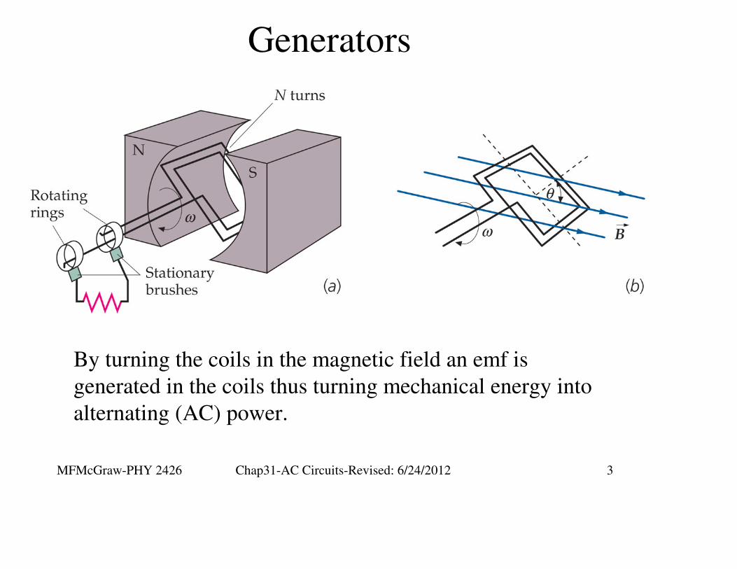
Generators
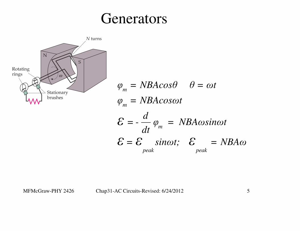
By turning the coils in the magnetic field an emf is
generated in the coils thus turning mechanical energy into
alternating (AC) power.
MFMcGraw-PHY 2426 Chap31-AC Circuits-Revised: 6/24/2012 4
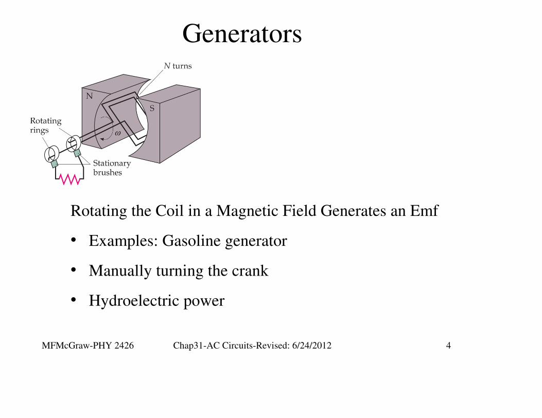
Generators
Rotating the Coil in a Magnetic Field Generates an Emf
• Examples: Gasoline generator
• Manually turning the crank
• Hydroelectric power
MFMcGraw-PHY 2426 Chap31-AC Circuits-Revised: 6/24/2012 5
Generators
m
m
m
peak peak
φ = NBAcosθ θ = ωt
φ = NBAcosωt
d= - φ = NBAωsinωt
dt
= sinωt; = NBAω
ε
ε ε ε
MFMcGraw-PHY 2426 Chap31-AC Circuits-Revised: 6/24/2012 6
Wave Nomenclature and RMS
Values

MFMcGraw-PHY 2426 Chap31-AC Circuits-Revised: 6/24/2012 7
Wave Nomenclature
Apeak-peak = Ap-p = 2Apeak = 2Ap; Ap = Ap-p /2

MFMcGraw-PHY 2426 Chap31-AC Circuits-Revised: 6/24/2012 8
ϕ
sinx = A ωt -
cos
ϕ
sin tx = A 2π -
cos T
( )( )
π
2
π π
2 2
x = A sin ωt -
x = A sinωt cos - sin cosωt
x = A sinωt (0) - (1)cosωt
x = -Acosωt
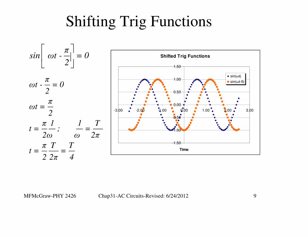
The minus sign means that the
phase is shifted to the right.
A plus sign indicated the phase
is shifted to the left
Shifting Trig Functions
MFMcGraw-PHY 2426 Chap31-AC Circuits-Revised: 6/24/2012 9
Shifting Trig Functions
πωt - = 0
2
πωt =
2
π 1 1 Tt = ; =
2ω ω 2π
π T Tt = =
2 2π 4
πsin ωt - = 0
2Shifted Trig Functions
-1.50
-1.00
-0.50
0.00
0.50
1.00
1.50
-3.00 -2.00 -1.00 0.00 1.00 2.00 3.00
Time
sin(ωt)
sin(ωt-δ)
MFMcGraw-PHY 2426 Chap31-AC Circuits-Revised: 6/24/2012 10
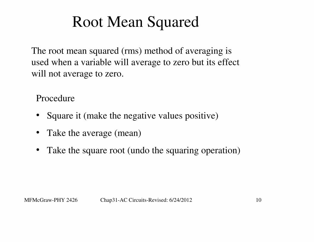
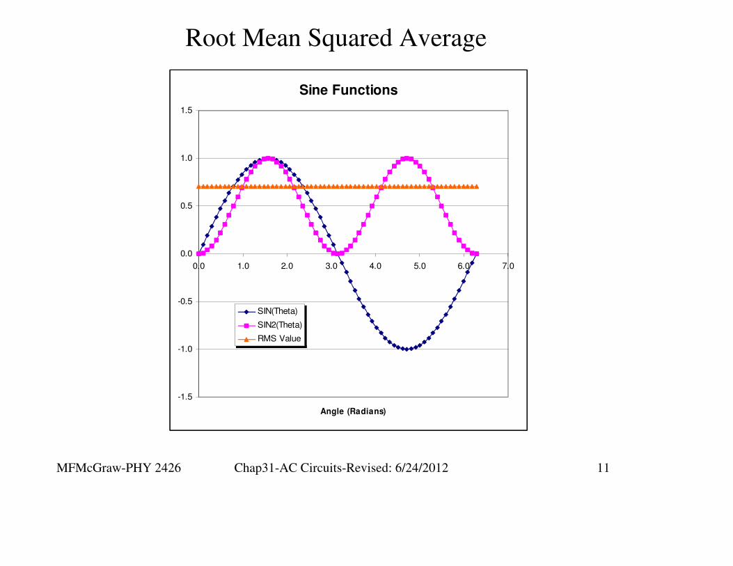
Root Mean Squared
Procedure
• Square it (make the negative values positive)
• Take the average (mean)
• Take the square root (undo the squaring operation)
The root mean squared (rms) method of averaging is
used when a variable will average to zero but its effect
will not average to zero.
MFMcGraw-PHY 2426 Chap31-AC Circuits-Revised: 6/24/2012 11
Sine Functions
-1.5
-1.0
-0.5
0.0
0.5
1.0
1.5
0.0 1.0 2.0 3.0 4.0 5.0 6.0 7.0
Angle (Radians)
SIN(Theta)
SIN2(Theta)
RMS Value
Root Mean Squared Average
MFMcGraw-PHY 2426 Chap31-AC Circuits-Revised: 6/24/2012 12
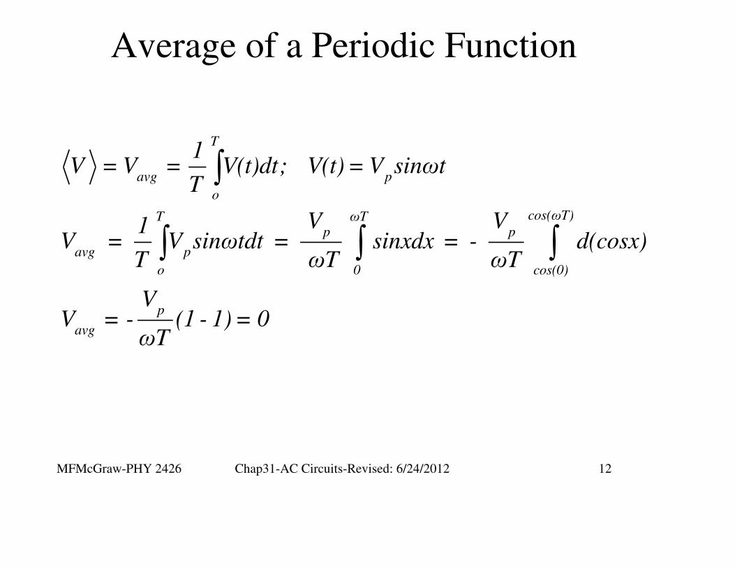
Average of a Periodic Function
∫
∫ ∫ ∫
T
avg p
o
cos(ωT)T ωTp p
avg p
o 0 cos(0)
p
avg
1V = V = V(t)dt; V(t) = V sinωt
T
V V1V = V sinωtdt = sinxdx = - d(cosx)
T ωT ωT
VV = - (1 - 1) = 0
ωT

MFMcGraw-PHY 2426 Chap31-AC Circuits-Revised: 6/24/2012 13
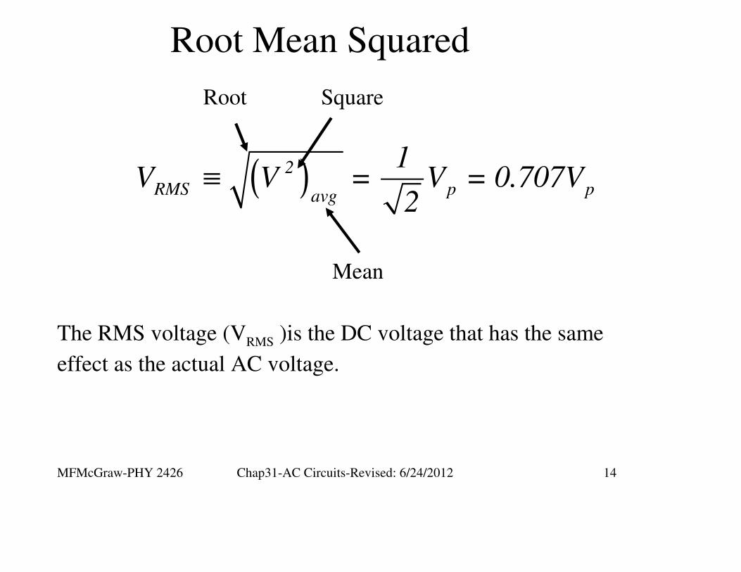
Root Mean Squared
( )
( )
( )
( )≡
∫
∫
T
2 2 2
pavg
o
2 2 2Tp p p2 2
avgo
2
p2
avg
2
RMS p pavg
1V = V = V (t)dt; V(t) = V sinωt
T
V V VV = sin ωtdt = π =
T ωT 2
VV =
2
1 V V = V = 0.707V
2
MFMcGraw-PHY 2426 Chap31-AC Circuits-Revised: 6/24/2012 14
Root Mean Squared
( )≡ 2
RMS p pavg
1 V V = V = 0.707V
2
Root Square
Mean
The RMS voltage (VRMS )is the DC voltage that has the same
effect as the actual AC voltage.
MFMcGraw-PHY 2426 Chap31-AC Circuits-Revised: 6/24/2012 15
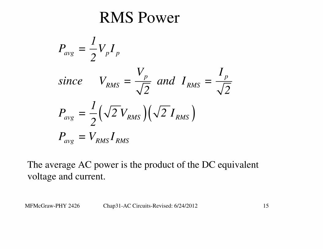
RMS Power
The average AC power is the product of the DC equivalent
voltage and current.
( )( )
avg p p
p p
RMS RMS
avg RMS RMS
avg RMS RMS
1P = V I
2
V Isince V = and I =
2 2
1P = 2 V 2 I
2
P = V I
MFMcGraw-PHY 2426 Chap31-AC Circuits-Revised: 6/24/2012 16
Resistor in an AC Circuit
MFMcGraw-PHY 2426 Chap31-AC Circuits-Revised: 6/24/2012 17
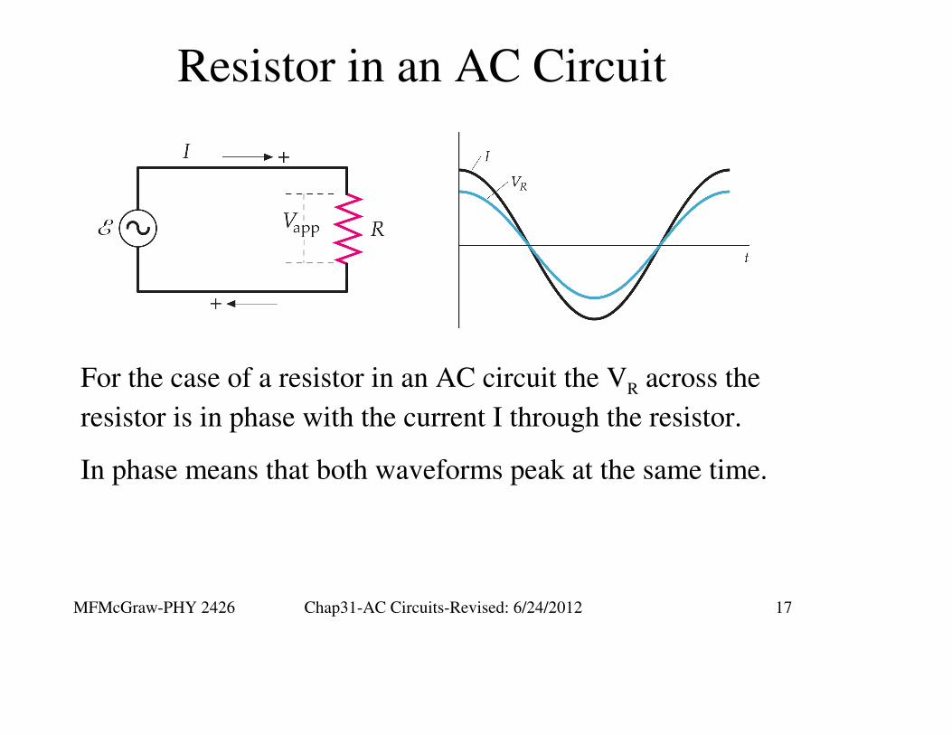
Resistor in an AC Circuit
For the case of a resistor in an AC circuit the VR across the
resistor is in phase with the current I through the resistor.
In phase means that both waveforms peak at the same time.
MFMcGraw-PHY 2426 Chap31-AC Circuits-Revised: 6/24/2012 18
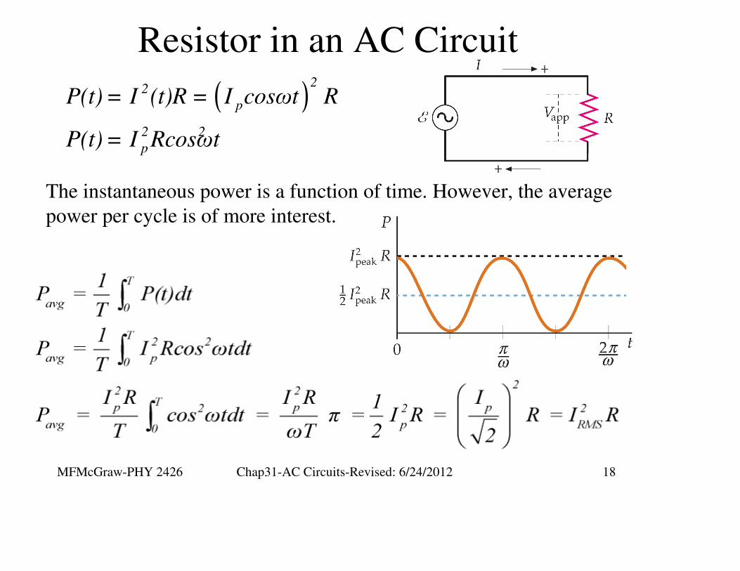
Resistor in an AC Circuit
( )2
2
p
2 2
p
P(t) = I (t)R = I cosωt R
P(t) = I Rcosωt
The instantaneous power is a function of time. However, the average
power per cycle is of more interest.

MFMcGraw-PHY 2426 Chap31-AC Circuits-Revised: 6/24/2012 19
Inductors in an AC Circuit
MFMcGraw-PHY 2426 Chap31-AC Circuits-Revised: 6/24/2012 20
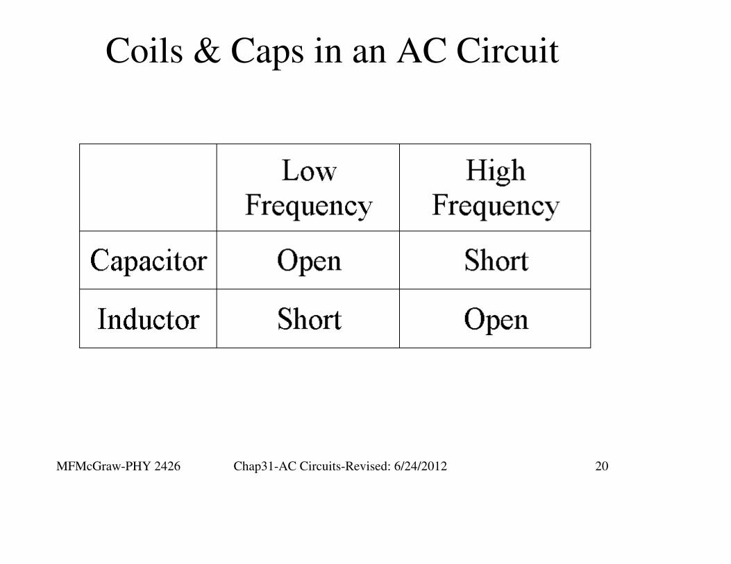
Coils & Caps in an AC Circuit

MFMcGraw-PHY 2426 Chap31-AC Circuits-Revised: 6/24/2012 21
Inductors in an AC Circuit
For the case of an inductor in an
AC circuit the VL across the
inductor is 900 ahead of the current
I through the inductor.

MFMcGraw-PHY 2426 Chap31-AC Circuits-Revised: 6/24/2012 22
Inductors in an AC Circuit
( )L peak
p
L peak L peak
p
L
L
VπI = I sinωt = cos ωt -
2ωL
V VI = =
ωL X
X =ωL
XL is the inductive reactance
MFMcGraw-PHY 2426 Chap31-AC Circuits-Revised: 6/24/2012 23
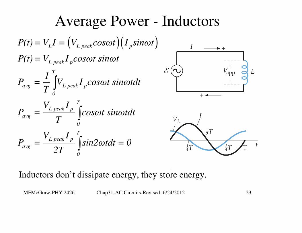
Average Power - Inductors
( )( )
∫
∫
∫
L L peak p
L peak p
T
avg L peak p
0
TL peak p
avg
0
TL peak p
avg
0
P(t) = V I = V cosωt I sinωt
P(t) = V I cosωt sinωt
1P = V I cosωt sinωtdt
T
V IP = cosωt sinωtdt
T
V IP = sin2ωtdt = 0
2T
Inductors don’t dissipate energy, they store energy.

MFMcGraw-PHY 2426 Chap31-AC Circuits-Revised: 6/24/2012 24
Average Power - Inductors
Inductors don’t dissipate energy, they
store energy.
The voltage and the current are out of
phase by 90o.
As we saw with Work, energy
changed only when a portion of the
force was in the direction of the
displacement.
In electrical circuits energy is
dissipated only if a portion of the
voltage is in phase with the current.
MFMcGraw-PHY 2426 Chap31-AC Circuits-Revised: 6/24/2012 25
Capacitors in an AC Circuit

MFMcGraw-PHY 2426 Chap31-AC Circuits-Revised: 6/24/2012 26
Capacitors in an AC Circuit
( )
C p C p
C C p p
p p
p p
V = cosωt = V cosωt
Q = V C = V Ccosωt = Q cosωt
dQI = = -ωQ sinωt = -I sinωt
dt
πI = -ωQ sinωt = I cos ωt +2
ε
For the case of a capacitor in an
AC circuit the VC across the
capacitor is 900 behind the current
I on the capacitor.

MFMcGraw-PHY 2426 Chap31-AC Circuits-Revised: 6/24/2012 27
Capacitors in an AC Circuit
Cp Cp
p p Cp
C
C
V VI =ωQ = ωCV = =
1 XωC
1X =
ωC
XC is the capacitive reactance.
MFMcGraw-PHY 2426 Chap31-AC Circuits-Revised: 6/24/2012 28
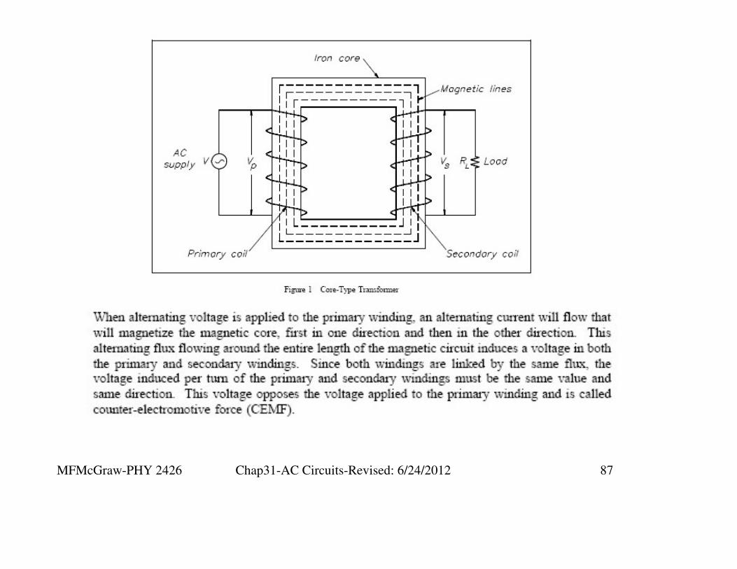
Electrical Transformers
MFMcGraw-PHY 2426 Chap31-AC Circuits-Revised: 6/24/2012 29
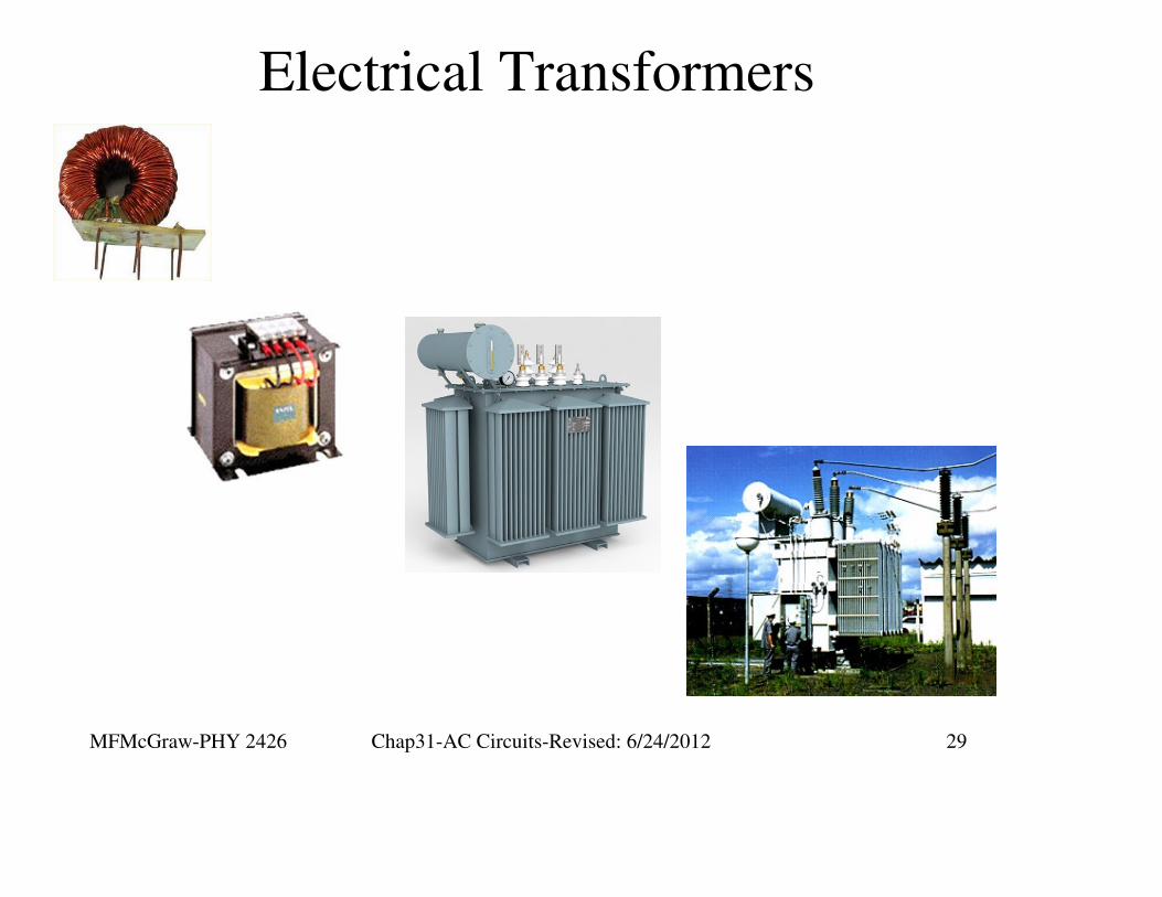
Electrical Transformers

MFMcGraw-PHY 2426 Chap31-AC Circuits-Revised: 6/24/2012 30
Electrical Transformers
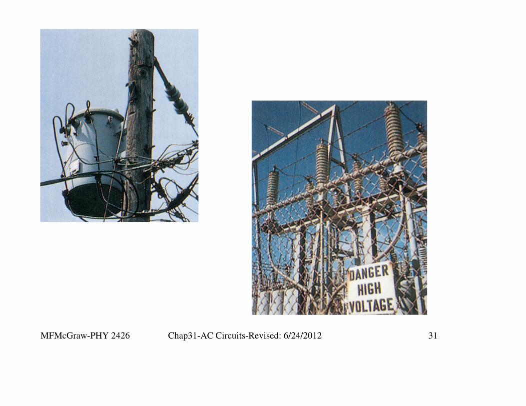
MFMcGraw-PHY 2426 Chap31-AC Circuits-Revised: 6/24/2012 31
MFMcGraw-PHY 2426 Chap31-AC Circuits-Revised: 6/24/2012 32
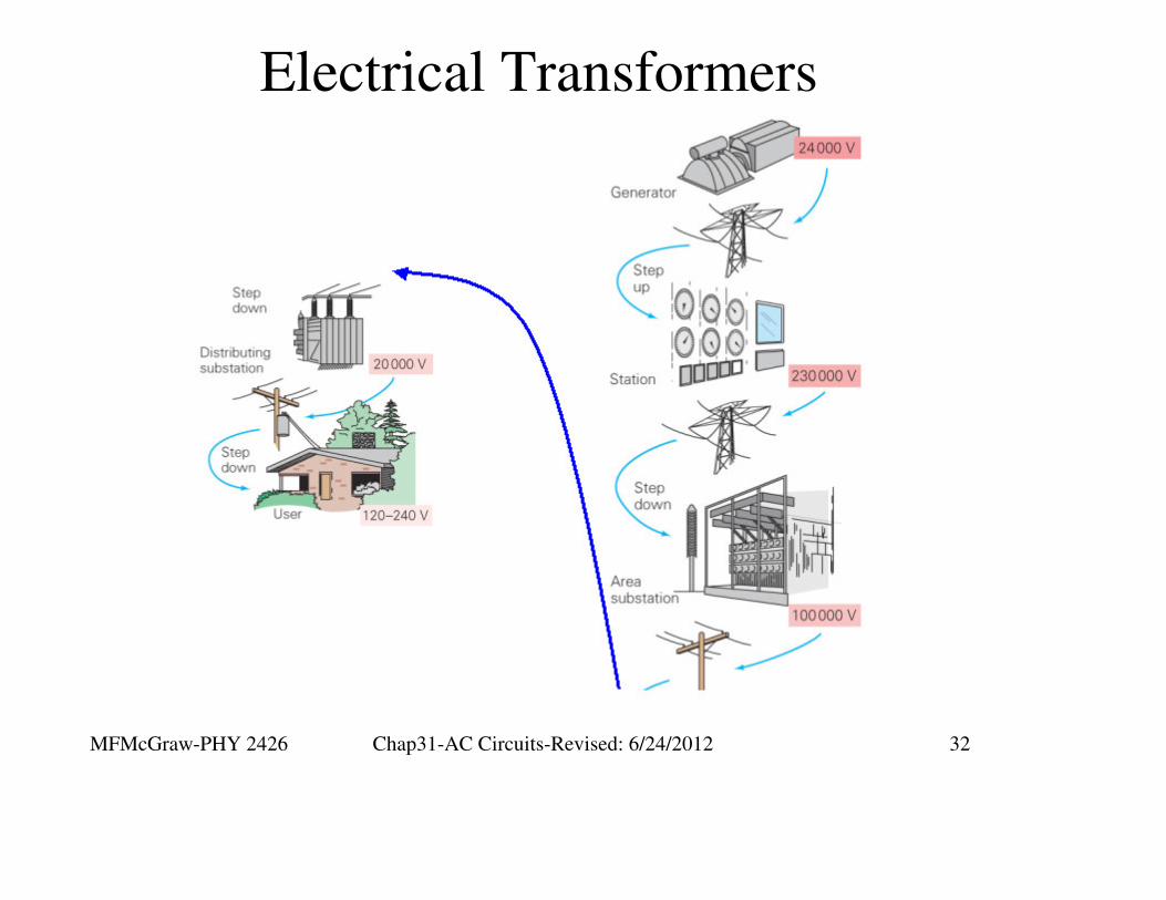
Electrical Transformers

MFMcGraw-PHY 2426 Chap31-AC Circuits-Revised: 6/24/2012 33
Electrical TransformersBoth coils see the same magnetic flux and the cross sectional
areas are the same
0
0 1 1 0 2 2
1 1 2 2
1
2 1
2
2
1 2 2
12 1 1
B = µ nI
µ n I = µ n I
n I = n I
nI = I
n
NI n NL= = =
NI n N
L
MFMcGraw-PHY 2426 Chap31-AC Circuits-Revised: 6/24/2012 34
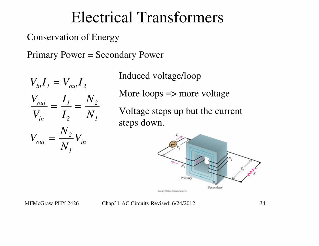
Electrical TransformersConservation of Energy
Primary Power = Secondary Power
in 1 out 2
out 1 2
in 2 1
2out in
1
V I = V I
V I N= =
V I N
NV = V
N
Induced voltage/loop
More loops => more voltage
Voltage steps up but the current
steps down.

MFMcGraw-PHY 2426 Chap31-AC Circuits-Revised: 6/24/2012 35
LC and RLC Circuits Without a
Generator
MFMcGraw-PHY 2426 Chap31-AC Circuits-Revised: 6/24/2012 36
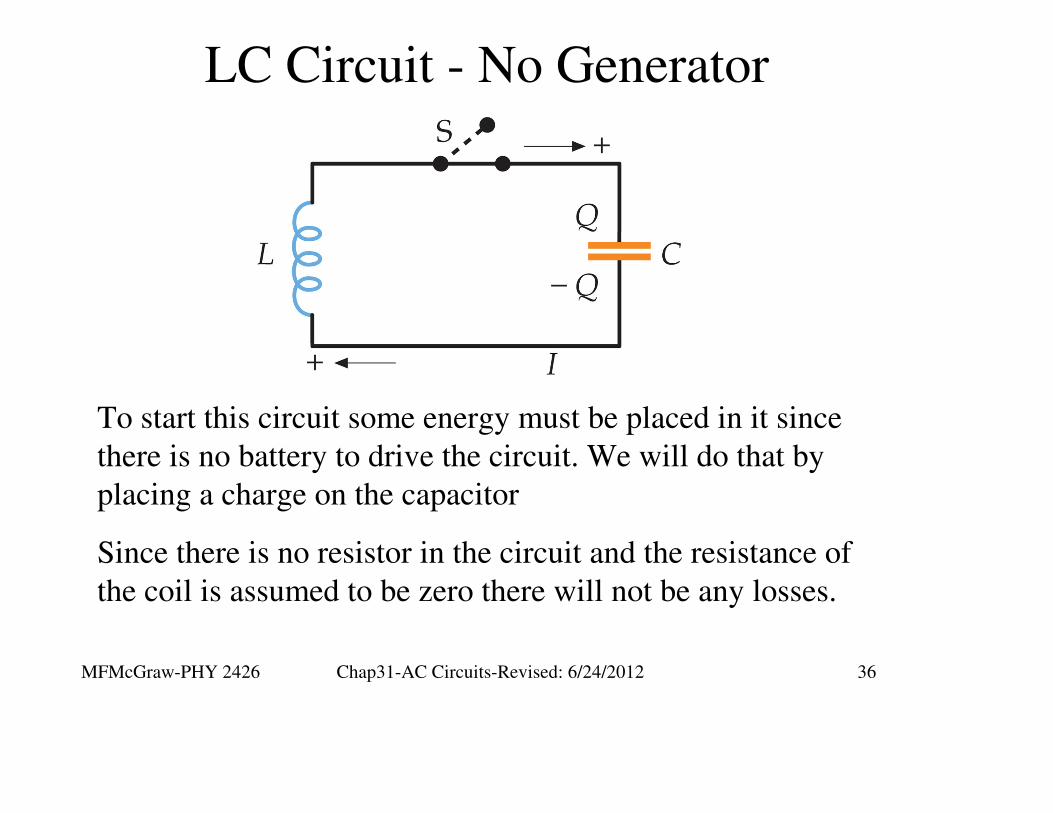
LC Circuit - No Generator
To start this circuit some energy must be placed in it since
there is no battery to drive the circuit. We will do that by
placing a charge on the capacitor
Since there is no resistor in the circuit and the resistance of
the coil is assumed to be zero there will not be any losses.

MFMcGraw-PHY 2426 Chap31-AC Circuits-Revised: 6/24/2012 37
LC Circuit - No Generator
Apply Kirchhoff’s rule
2
2
2
2
R
dI QL + = 0
dt C
dQSince I =
dt
d Q QL + = 0
dt C
d Q 1= - Q
dt LC
1ω =
LC
This is the harmonic
oscillator equation
MFMcGraw-PHY 2426 Chap31-AC Circuits-Revised: 6/24/2012 38
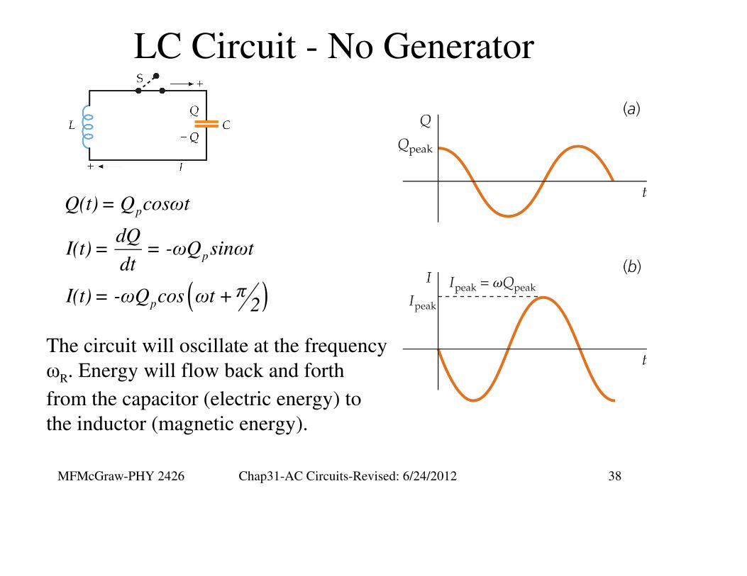
LC Circuit - No Generator
( )
p
p
p
Q(t) = Q cosωt
dQI(t) = = -ωQ sinωt
dt
πI(t) = -ωQ cos ωt +2
The circuit will oscillate at the frequency
ωR. Energy will flow back and forth
from the capacitor (electric energy) to
the inductor (magnetic energy).

MFMcGraw-PHY 2426 Chap31-AC Circuits-Revised: 6/24/2012 39
RLC Circuit - No Generator
Like the LC circuit some energy must initially be placed in
this circuit since there is no battery to drive the circuit. Again
we will do this by placing a charge on the capacitor
Since there is a resistor in the circuit now there will be losses
as the energy passes through the resistor.
MFMcGraw-PHY 2426 Chap31-AC Circuits-Revised: 6/24/2012 40
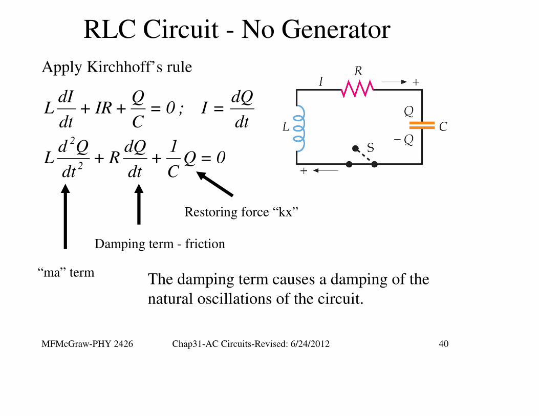
RLC Circuit - No Generator
Apply Kirchhoff’s rule
2
2
dI Q dQL + IR + = 0 ; I =
dt C dt
d Q dQ 1L + R + Q = 0
dt dt C
“ma” term
Damping term - friction
Restoring force “kx”
The damping term causes a damping of the
natural oscillations of the circuit.

MFMcGraw-PHY 2426 Chap31-AC Circuits-Revised: 6/24/2012 41
RLC Circuit - No Generator

MFMcGraw-PHY 2426 Chap31-AC Circuits-Revised: 6/24/2012 42
RLC Circuit - No Generator
2
22 2
22 2
dI QL + RI + = 0
dt C
dI QILI + I R + = 0
dt C
d 1 d 1 QLI + I R + = 0
dt 2 dt 2 C
d 1 1 QLI + = -I R
dt 2 2 C
The rate of change of the
stored energy= - Power dissipated in the
resistor
Multiply by I

MFMcGraw-PHY 2426 Chap31-AC Circuits-Revised: 6/24/2012 43
Series RLC Circuit with Generator
We have already examined the components in this circuit to
understand the phase relations of the voltage and current of
each component
Now we will examine the power relationships
MFMcGraw-PHY 2426 Chap31-AC Circuits-Revised: 6/24/2012 44
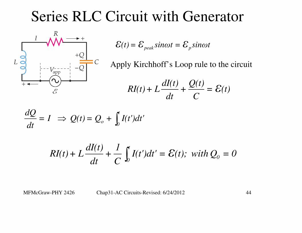
Series RLC Circuit with Generator
peak p(t) = sinωt = sinωtε ε ε
dI(t) Q(t)RI(t)+ L + = (t)
dt Cε
Apply Kirchhoff’s Loop rule to the circuit
⇒ ∫t
o0
dQ= I Q(t) = Q + I(t')dt'
dt
∫t
00
dI(t) 1RI(t)+ L + I(t')dt' = (t); with Q = 0
dt Cε

MFMcGraw-PHY 2426 Chap31-AC Circuits-Revised: 6/24/2012 45
Series RLC Circuit with Generator
ω
⇒
∫ ∫
p
t t p
p p0 0
Steady state I(t) = I sinωt
IdI(t) = I cosωt; I(t')dt' = I sinωt'dt' = - cosωt
dt ω
∫t
0
dI(t) 1RI(t)+ L + I(t')dt' = (t)
dt Cε
p p pp
1RI sinωt +ωLI cosωt - I cosωt = sinωt
ωCε
MFMcGraw-PHY 2426 Chap31-AC Circuits-Revised: 6/24/2012 46
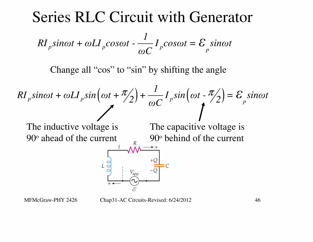
Series RLC Circuit with Generator
( ) ( )π πp p p
p
1RI sinωt +ωLI sin ωt + + I sin ωt - = sinωt
2 2ωCε
Change all “cos” to “sin” by shifting the angle
The inductive voltage is
90o ahead of the current
The capacitive voltage is
90o behind of the current
p p pp
1RI sinωt +ωLI cosωt - I cosωt = sinωt
ωCε

MFMcGraw-PHY 2426 Chap31-AC Circuits-Revised: 6/24/2012 47
Impedance in a Series RLC Circuit
( ) ( )π πp p p
p
1RI sinωt +ωLI sin ωt + + I sin ωt - = sinωt
2 2ωCε
p p p
L p C p
L C
R L C
RI ωLI I ωC
X I X I
X = ωL X = 1 ωC
The coefficients are voltages
The R and XL and XC values are
called impedances. That is a
generlized term for resistance
since they all have units of ohms.
XL is the inductive reactance.
XC is the capacitive reactance.
MFMcGraw-PHY 2426 Chap31-AC Circuits-Revised: 6/24/2012 48
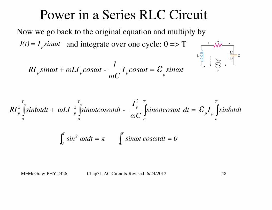
Power in a Series RLC CircuitNow we go back to the original equation and multiply by
pI(t) = I sinωt and integrate over one cycle: 0 => T
∫ ∫ ∫ ∫2T T T Tp2 2 2 2
p p p p
o o o o
IRI sinωtdt + ωLI sinωtcosωtdt - sinωtcosωt dt = I sinωtdt
ωCε
p p pp
1RI sinωt +ωLI cosωt - I cosωt = sinωt
ωCε
∫ ∫T T
2
0 0sin ωtdt = π sinωt cosωtdt = 0
MFMcGraw-PHY 2426 Chap31-AC Circuits-Revised: 6/24/2012 49
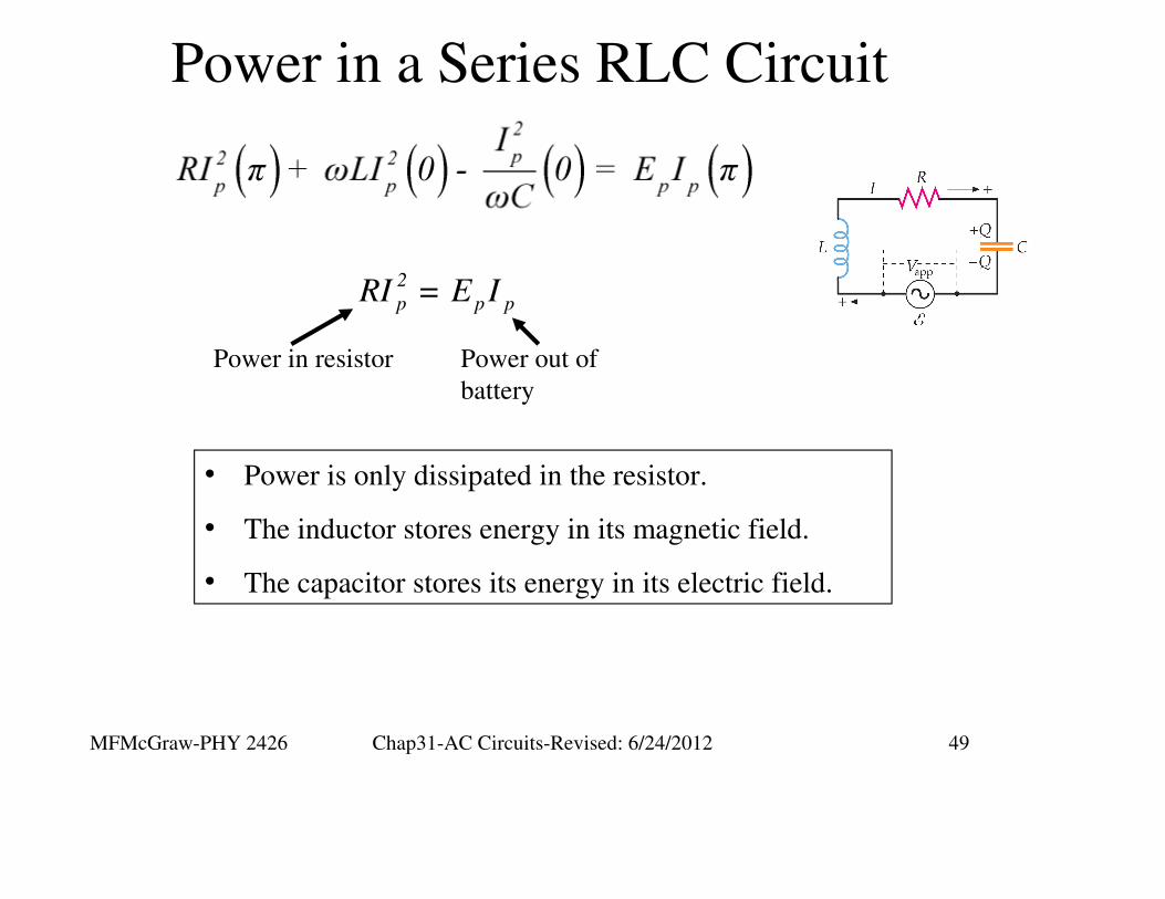
Power in a Series RLC Circuit
2
p p pRI = E I
• Power is only dissipated in the resistor.
• The inductor stores energy in its magnetic field.
• The capacitor stores its energy in its electric field.
Power in resistor Power out of
battery
MFMcGraw-PHY 2426 Chap31-AC Circuits-Revised: 6/24/2012 50
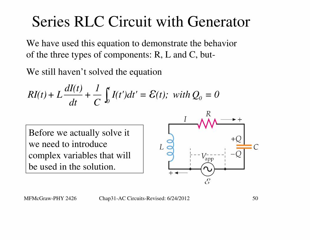
Series RLC Circuit with Generator
∫t
00
dI(t) 1RI(t)+ L + I(t')dt' = (t); with Q = 0
dt Cε
We have used this equation to demonstrate the behavior
of the three types of components: R, L and C, but-
We still haven’t solved the equation
Before we actually solve it
we need to introduce
complex variables that will
be used in the solution.
MFMcGraw-PHY 2426 Chap31-AC Circuits-Revised: 6/24/2012 51
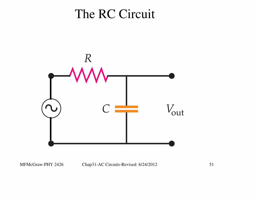
The RC Circuit
MFMcGraw-PHY 2426 Chap31-AC Circuits-Revised: 6/24/2012 52
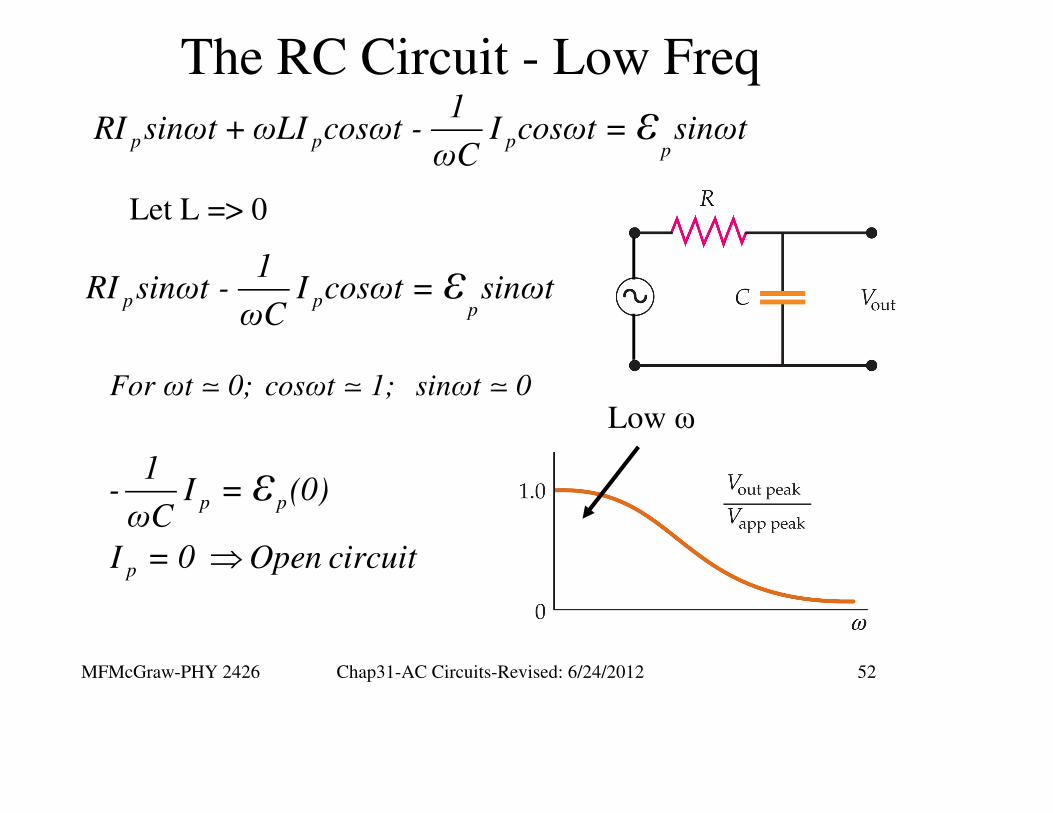
The RC Circuit - Low Freq
p p pp
1RI sinωt +ωLI cosωt - I cosωt = sinωt
ωCε
p pp
1RI sinωt - I cosωt = sinωt
ωCε
Low ω
Let L => 0
⇒
p p
p
1- I = (0)ωC
I = 0 Open circuit
ε
For ωt 0; cosωt 1; sinωt 0
MFMcGraw-PHY 2426 Chap31-AC Circuits-Revised: 6/24/2012 53
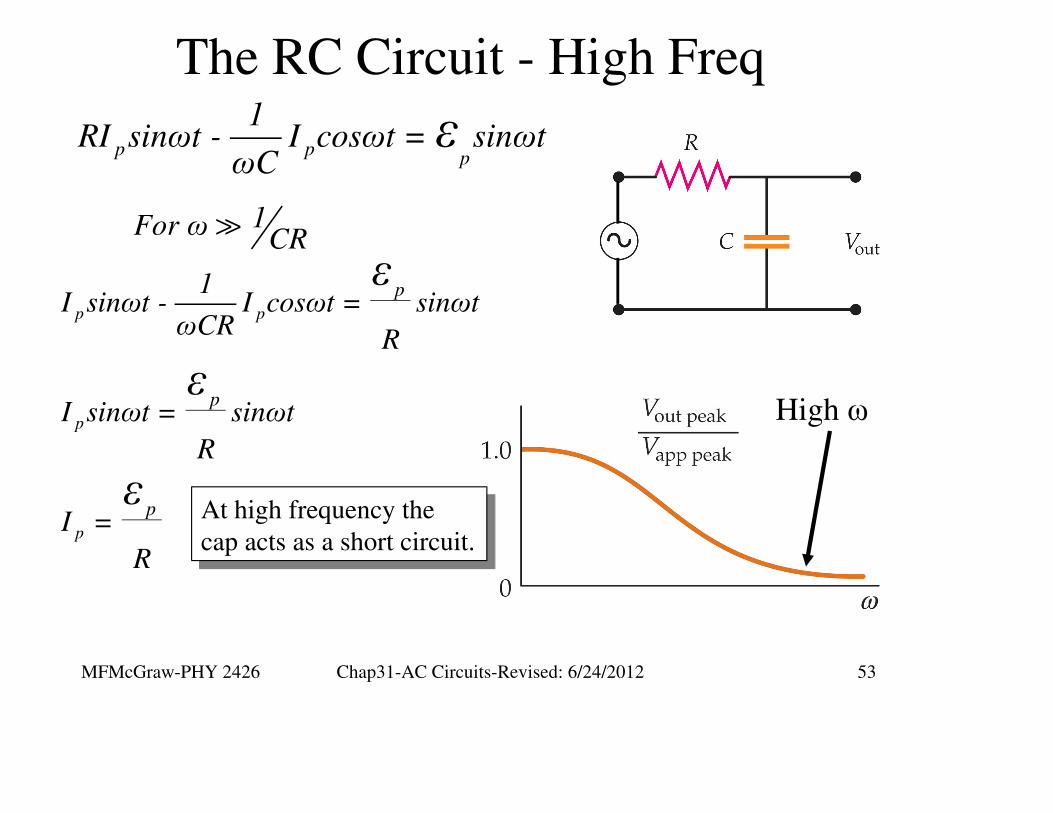
The RC Circuit - High Freq
p pp
1RI sinωt - I cosωt = sinωt
ωCε
High ω
p p
p
p
p
p
p
1I sinωt - I cosωt = sinωt
ωCRR
I sinωt = sinωt
R
I =
R
ε
ε
εAt high frequency the
cap acts as a short circuit.
At high frequency the
cap acts as a short circuit.
1For ω CR

MFMcGraw-PHY 2426 Chap31-AC Circuits-Revised: 6/24/2012 54
The RL Circuit
MFMcGraw-PHY 2426 Chap31-AC Circuits-Revised: 6/24/2012 55
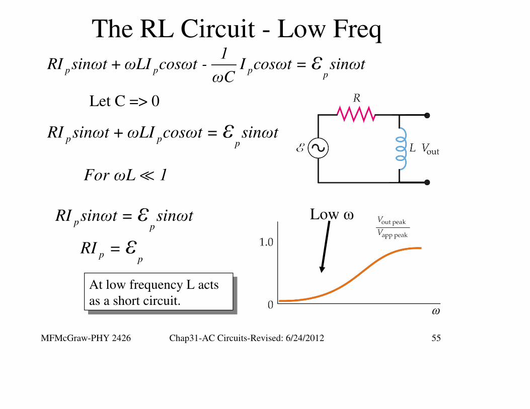
The RL Circuit - Low Freq
p p pp
1RI sinωt +ωLI cosωt - I cosωt = sinωt
ωCε
Low ω
p pp
RI sinωt +ωLI cosωt = sinωtε
pp
pp
RI sinωt = sinωt
RI =
ε
ε
At low frequency L acts
as a short circuit.
At low frequency L acts
as a short circuit.
Let C => 0
For ωL 1
MFMcGraw-PHY 2426 Chap31-AC Circuits-Revised: 6/24/2012 56
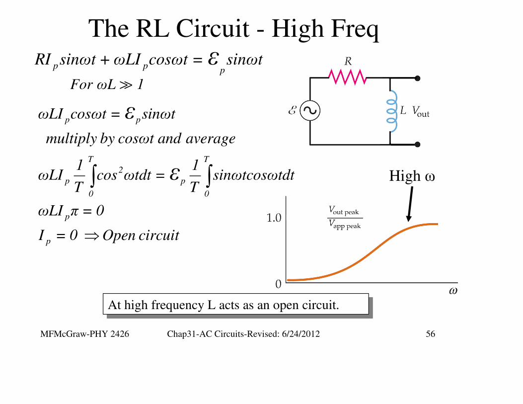
The RL Circuit - High Freq
For ωL 1
High ω
At high frequency L acts as an open circuit.At high frequency L acts as an open circuit.
p pp
RI sinωt +ωLI cosωt = sinωtε
⇒
∫ ∫
p p
T T
2
p p
0 0
p
p
ωLI cosωt = sinωt
multiply by cosωt and average
1 1ωLI cos ωtdt = sinωtcosωtdt
T T
ωLI π = 0
I = 0 Open circuit
ε
ε

MFMcGraw-PHY 2426 Chap31-AC Circuits-Revised: 6/24/2012 57
Coils & Caps in an AC Circuit

MFMcGraw-PHY 2426 Chap31-AC Circuits-Revised: 6/24/2012 58
Complex Numbers for AC Circuits

MFMcGraw-PHY 2426 Chap31-AC Circuits-Revised: 6/24/2012 59
Complex Numbers for AC Circuits
( )
( )( )
( )
2
3 2
4 2 2
5 4
j = -1
j = jj = -1 -1 = -1
j = jj = j -1 = -j
j = j j = -1 -1 = +1
j = jj = j +1 = j
The basic complex (imaginary) number is “i.”
To avoid confusion we replace “i” with “j”
MFMcGraw-PHY 2426 Chap31-AC Circuits-Revised: 6/24/2012 60
Complex Numbers for AC Circuits
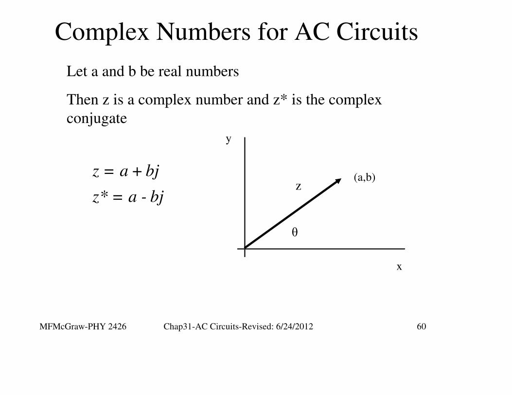
Let a and b be real numbers
Then z is a complex number and z* is the complex
conjugate
z = a + bj
z* = a - bj
x
y
θ
z(a,b)

MFMcGraw-PHY 2426 Chap31-AC Circuits-Revised: 6/24/2012 61
Complex Numbers for AC Circuits
The magnitude of z
( ) ( ) ( )( )
2 2 2
2 2
Magn z = z = z * z = a - bj a + bj
z = a + abj - abj - j b
z = a + b
x
y
θ
z(a,b)
( )( )
-1
jθ
b btanθ = ; θ = tana a
z = z cosθ + jsinθ = z e
The exponential representation of a
complex number will prove useful in
solving the RLC differenial eqn.

MFMcGraw-PHY 2426 Chap31-AC Circuits-Revised: 6/24/2012 62
Complex Numbers for AC Circuits
x
y
θ
z(a,b)
( ) jθz = z cosθ + jsinθ = z e
e jθ can be viewed as a rotation
operator in a complex space
πj2
jπ
3πj2
j2π 0
e = j
e = -1
e = -j
e = e = +1
MFMcGraw-PHY 2426 Chap31-AC Circuits-Revised: 6/24/2012 63
Why Complex Numbers ?
x
y
θ
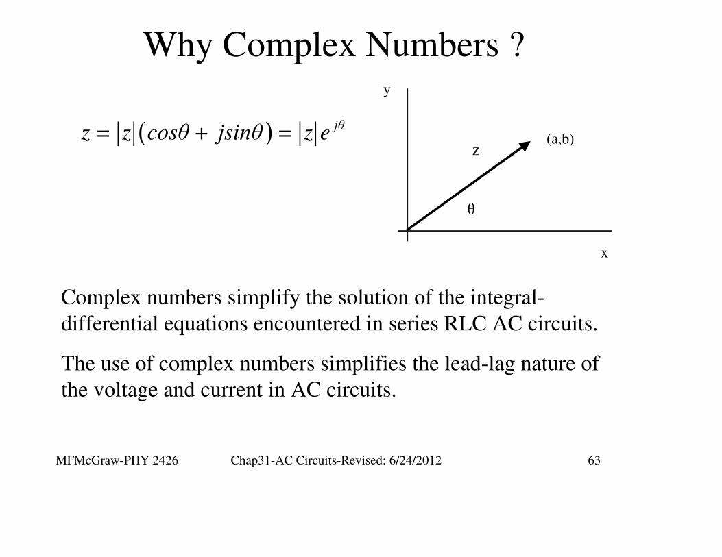
z(a,b)( ) jθ
z = z cosθ + jsinθ = z e
Complex numbers simplify the solution of the integral-
differential equations encountered in series RLC AC circuits.
The use of complex numbers simplifies the lead-lag nature of
the voltage and current in AC circuits.
MFMcGraw-PHY 2426 Chap31-AC Circuits-Revised: 6/24/2012 64
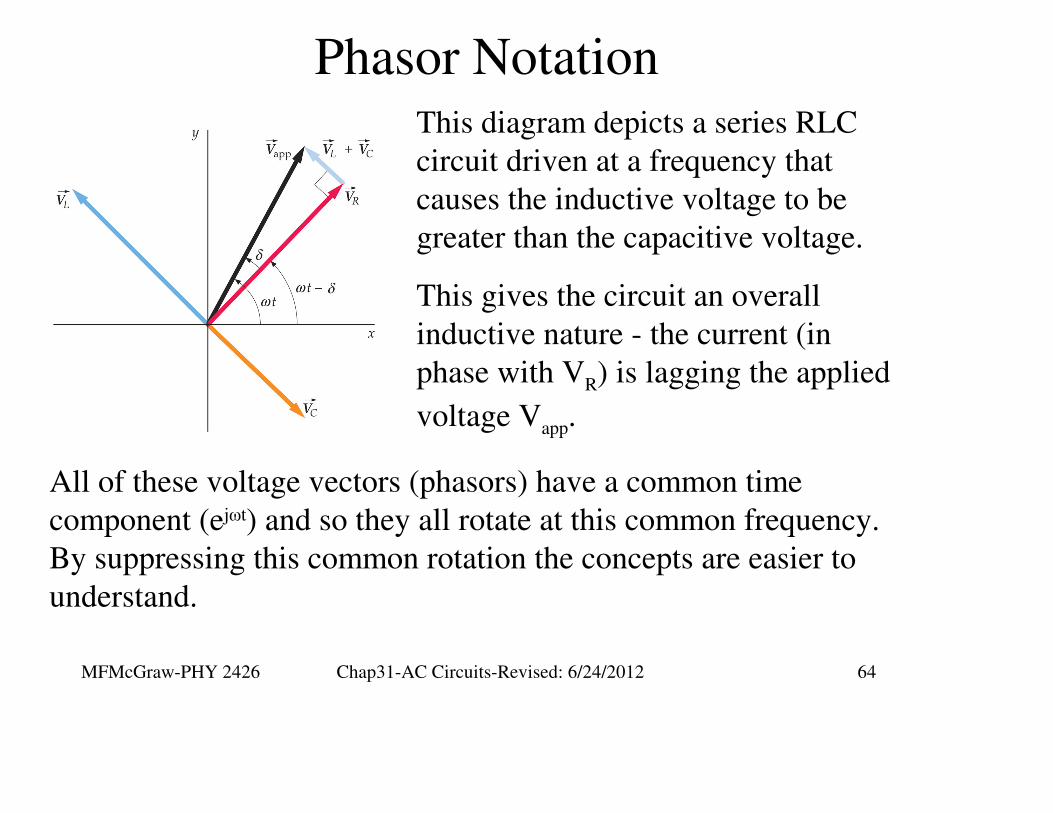
Phasor NotationThis diagram depicts a series RLC
circuit driven at a frequency that
causes the inductive voltage to be
greater than the capacitive voltage.
This gives the circuit an overall
inductive nature - the current (in
phase with VR) is lagging the applied
voltage Vapp.
All of these voltage vectors (phasors) have a common time
component (ejωt) and so they all rotate at this common frequency.
By suppressing this common rotation the concepts are easier to
understand.
MFMcGraw-PHY 2426 Chap31-AC Circuits-Revised: 6/24/2012 65
RLC Circuit Solution
∫t
0
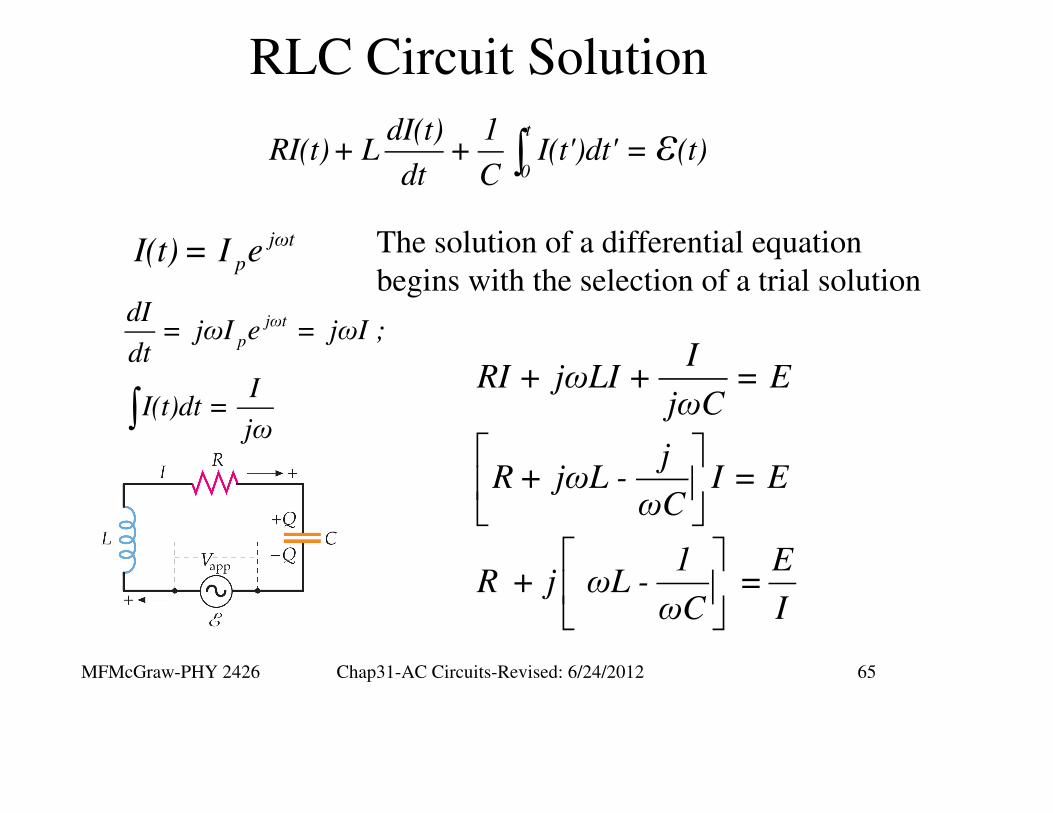
dI(t) 1RI(t)+ L + I(t')dt' = (t)
dt Cε
The solution of a differential equation
begins with the selection of a trial solution
jωt
pI(t) = I e
∫
jωt
p
dI= jωI e = jωI ;
dt
II(t)dt =
jω
IRI + jωLI + = E
jωC
jR + jωL - I = E
ωC
1 ER + j ωL - =
ωC I
MFMcGraw-PHY 2426 Chap31-AC Circuits-Revised: 6/24/2012 66
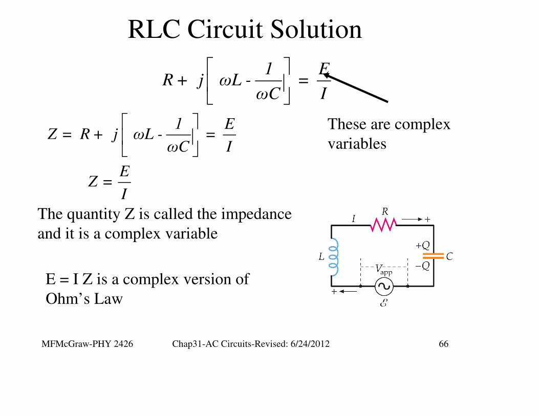
RLC Circuit Solution
1 ER + j ωL - =
ωC I
These are complex
variables
1 EZ = R + j ωL - =
ωC I
E Z =
I
The quantity Z is called the impedance
and it is a complex variable
E = I Z is a complex version of
Ohm’s Law
MFMcGraw-PHY 2426 Chap31-AC Circuits-Revised: 6/24/2012 67
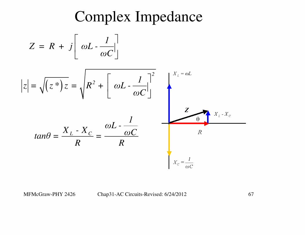
Complex Impedance
1Z = R + j ωL -
ωC
( )
2
2 1z = z * z = R + ωL -
ωC
L C
1ωL -
X - X ωCtanθ = =R R
MFMcGraw-PHY 2426 Chap31-AC Circuits-Revised: 6/24/2012 68
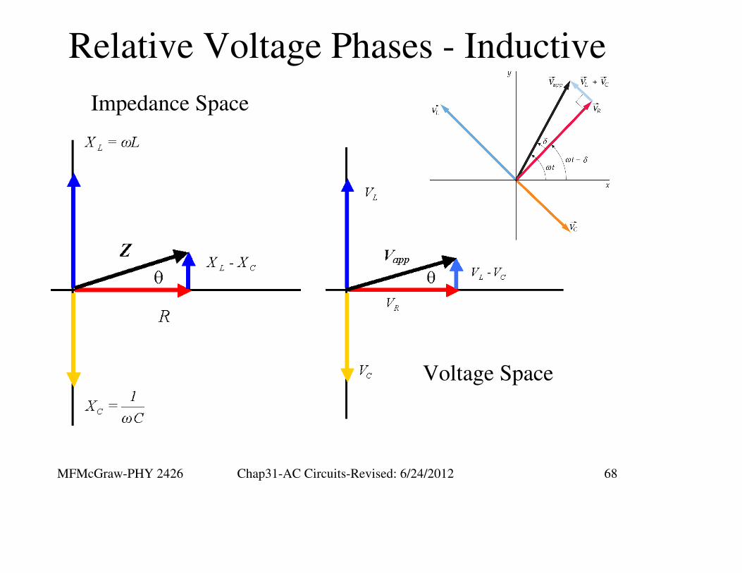
Relative Voltage Phases - Inductive
Impedance Space
Voltage Space
MFMcGraw-PHY 2426 Chap31-AC Circuits-Revised: 6/24/2012 69
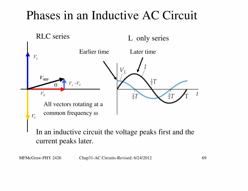
Phases in an Inductive AC Circuit
In an inductive circuit the voltage peaks first and the
current peaks later.
Later timeEarlier time
All vectors rotating at a
common frequency ω
RLC series L only series

MFMcGraw-PHY 2426 Chap31-AC Circuits-Revised: 6/24/2012 70
Phases in a Capacitive AC Circuit
In capacitive circuit the current peaks first and the
voltage peaks later.
Later timeEarlier time
All vectors rotating at a
common frequency ω
RLC series C only series
MFMcGraw-PHY 2426 Chap31-AC Circuits-Revised: 6/24/2012 71
RLC Series AC Circuit
Example
MFMcGraw-PHY 2426 Chap31-AC Circuits-Revised: 6/24/2012 72
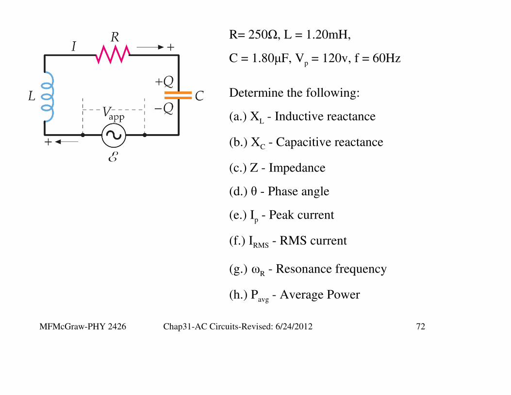
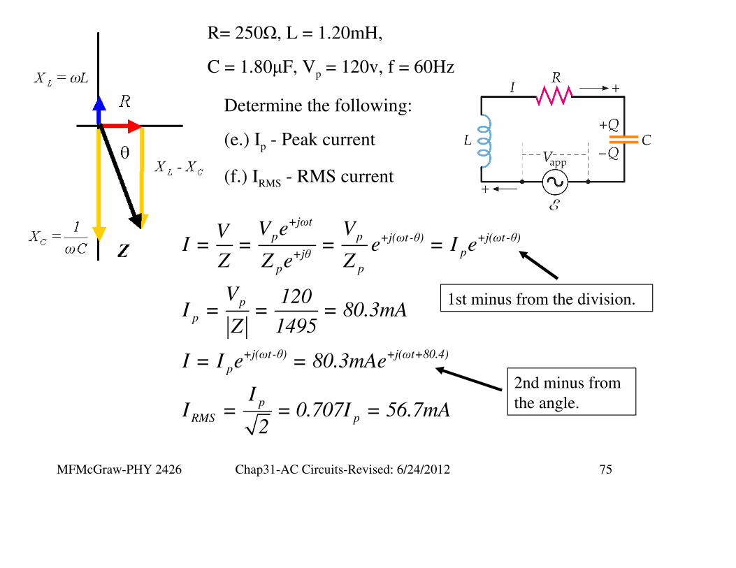
R= 250Ω, L = 1.20mH,
C = 1.80µF, Vp = 120v, f = 60Hz
Determine the following:
(a.) XL - Inductive reactance
(b.) XC - Capacitive reactance
(c.) Z - Impedance
(d.) θ - Phase angle
(e.) Ip - Peak current
(f.) IRMS - RMS current
(g.) ωR - Resonance frequency
(h.) Pavg - Average Power
MFMcGraw-PHY 2426 Chap31-AC Circuits-Revised: 6/24/2012 73
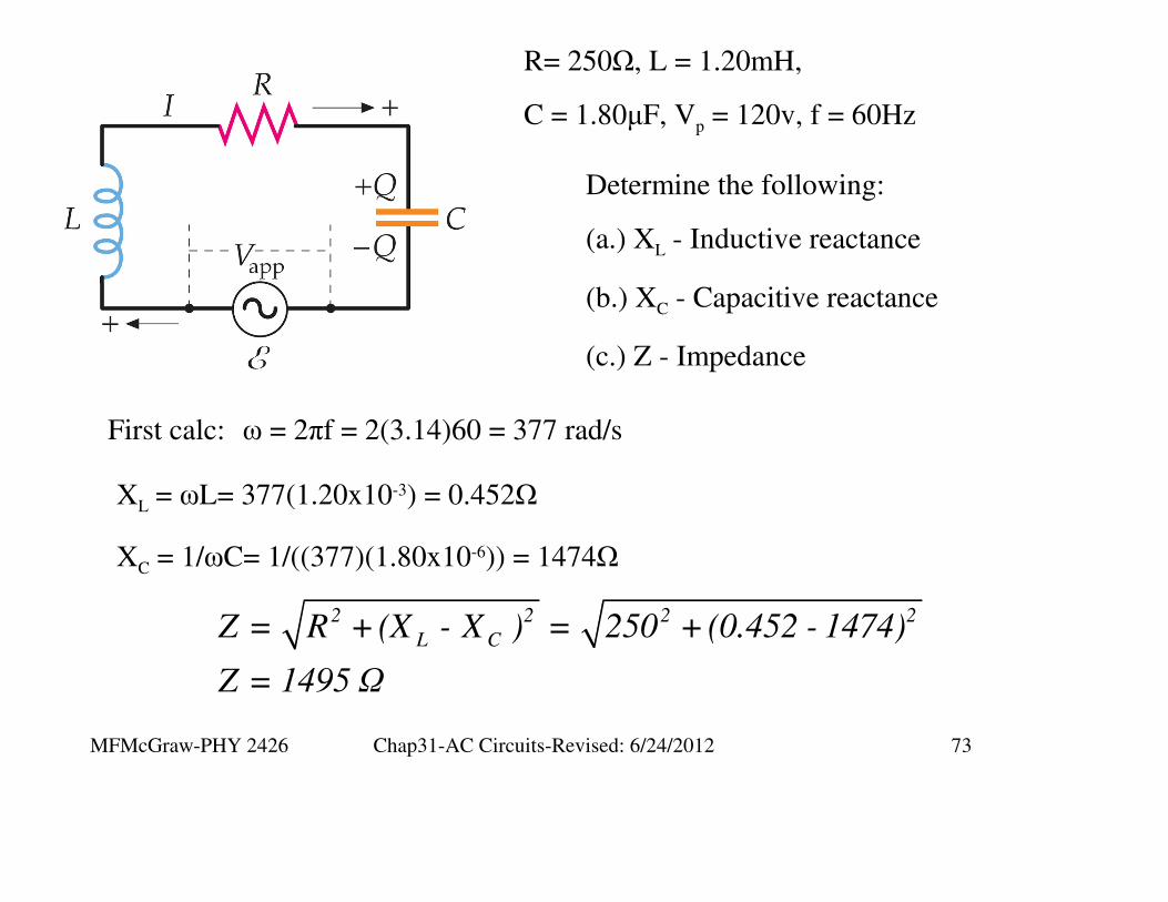
R= 250Ω, L = 1.20mH,
C = 1.80µF, Vp = 120v, f = 60Hz
Determine the following:
(a.) XL - Inductive reactance
(b.) XC - Capacitive reactance
(c.) Z - Impedance
XL = ωL= 377(1.20x10⁻³) = 0.452Ω
First calc: ω = 2πf = 2(3.14)60 = 377 rad/s
XC = 1/ωC= 1/((377)(1.80x10-6)) = 1474Ω
2 2 2 2
L CZ = R +(X - X ) = 250 +(0.452 - 1474)
Z = 1495 Ω
MFMcGraw-PHY 2426 Chap31-AC Circuits-Revised: 6/24/2012 74
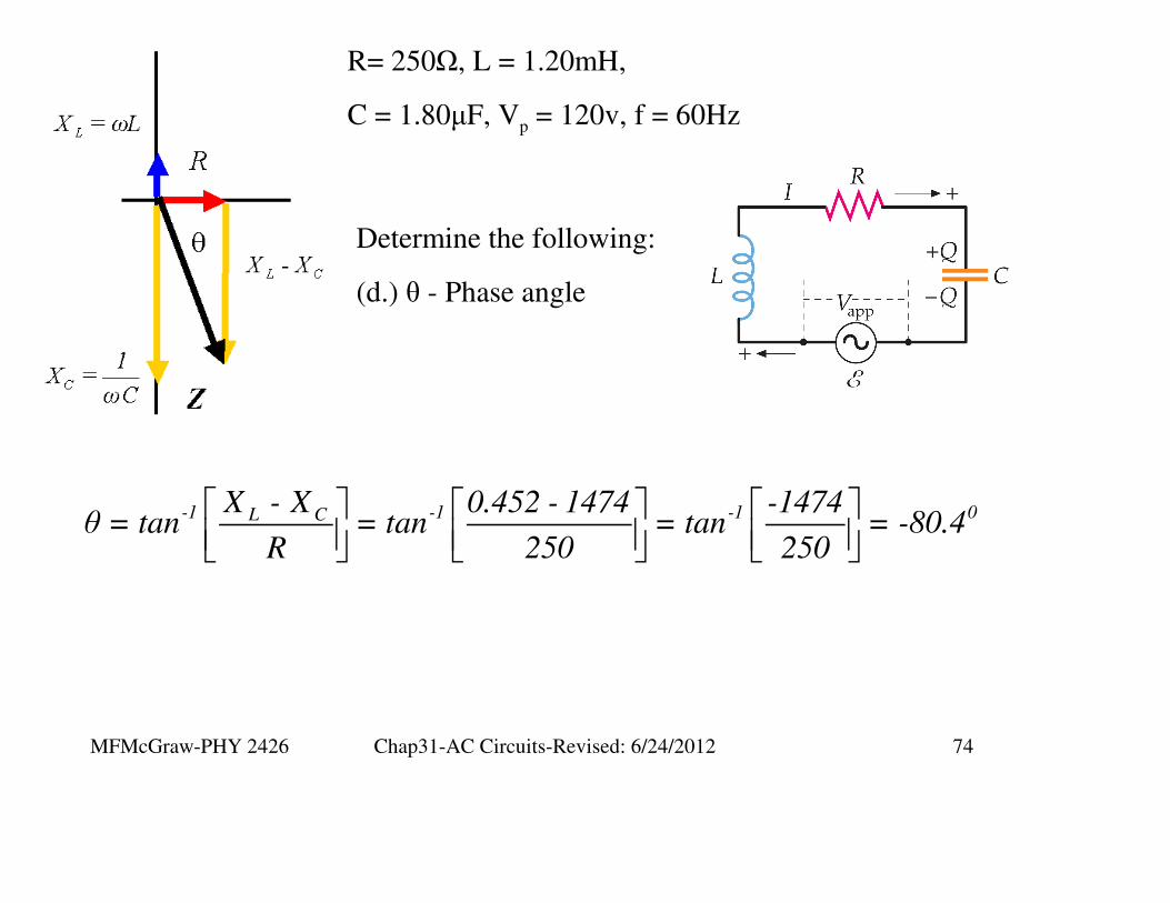
R= 250Ω, L = 1.20mH,
C = 1.80µF, Vp = 120v, f = 60Hz
Determine the following:
(d.) θ - Phase angle
-1 -1 -1 0L CX - X 0.452 - 1474 -1474θ = tan = tan = tan = -80.4
R 250 250
MFMcGraw-PHY 2426 Chap31-AC Circuits-Revised: 6/24/2012 75
R= 250Ω, L = 1.20mH,
C = 1.80µF, Vp = 120v, f = 60Hz
Determine the following:
(e.) Ip - Peak current
(f.) IRMS - RMS current
+jωt
p p +j(ωt -θ) +j(ωt -θ)
p+jθ
p p
p
p
+j(ωt-θ) +j(ωt+80.4)
p
p
RMS p
V e VVI = = = e = I e
Z Z e Z
V 120I = = = 80.3mA
Z 1495
I = I e = 80.3mAe
II = = 0.707I = 56.7mA
2
1st minus from the division.
2nd minus from
the angle.
MFMcGraw-PHY 2426 Chap31-AC Circuits-Revised: 6/24/2012 76
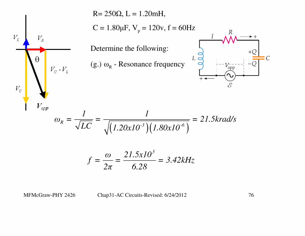
R= 250Ω, L = 1.20mH,
C = 1.80µF, Vp = 120v, f = 60Hz
Determine the following:
(g.) ωR - Resonance frequency
( )( )R
-3 -6
1 1ω = = = 21.5krad/s
LC 1.20x10 1.80x10
3ω 21.5x10f = = = 3.42kHz
2π 6.28

MFMcGraw-PHY 2426 Chap31-AC Circuits-Revised: 6/24/2012 77
R= 250Ω, L = 1.20mH,
C = 1.80µF, Vp = 120v, f = 60Hz
Determine the following:
(h.) Pavg - Average Power
( )( )
+jωt +j(ωt+80.4)
p p
+jωt -j(ωt+80.4) +j(ωt -ωt-80.4)
p p p p
p p-j(80.4) -j(80.4) -j(80.4)
p p RMS RMS
1S = VI * V = V e I = I e
2
1 1S = V e I e = V I e
2 2
V I1S = V I e = e = V I e
2 2 2
MFMcGraw-PHY 2426 Chap31-AC Circuits-Revised: 6/24/2012 78
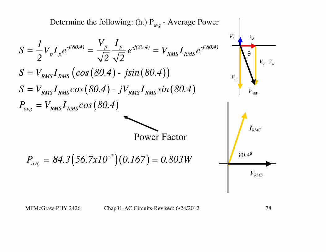
Determine the following: (h.) Pavg - Average Power
( ) ( )( )
( ) ( )
( )
p p-j(80.4) -j(80.4) -j(80.4)
p p RMS RMS
RMS RMS
RMS RMS RMS RMS
avg RMS RMS
V I1S = V I e = e = V I e
2 2 2
S = V I cos 80.4 - jsin 80.4
S = V I cos 80.4 - jV I sin 80.4
P = V I cos 80.4
Power Factor
( )( )-3
avgP = 84.3 56.7x10 0.167 = 0.803W
MFMcGraw-PHY 2426 Chap31-AC Circuits-Revised: 6/24/2012 79
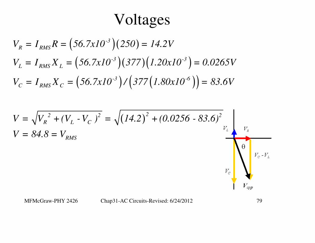
Voltages
( )( )
( )( )( )
( ) ( )( )
( )
-3
R RMS
-3 -3
L RMS L
-3 -6
C RMS C
22 2 2
R L C
RMS
V = I R = 56.7x10 250 = 14.2V
V = I X = 56.7x10 377 1.20x10 = 0.0265V
V = I X = 56.7x10 / 377 1.80x10 = 83.6V
V = V + (V - V ) = 14.2 + (0.0256 - 83.6)
V = 84.8 = V
MFMcGraw-PHY 2426 Chap31-AC Circuits-Revised: 6/24/2012 80
Resonance in a Series RLC Circuit

MFMcGraw-PHY 2426 Chap31-AC Circuits-Revised: 6/24/2012 81
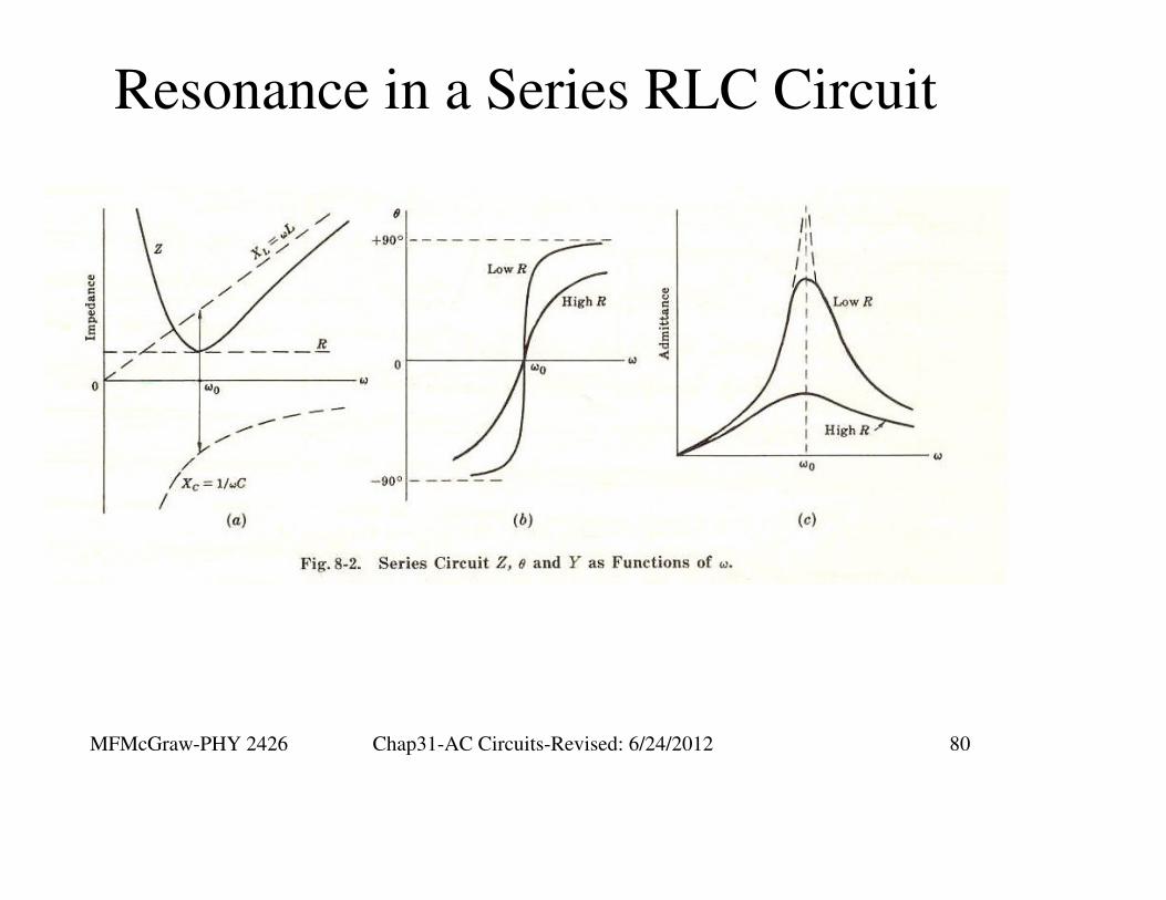
Resonance in a Series RLC
Circuit
MFMcGraw-PHY 2426 Chap31-AC Circuits-Revised: 6/24/2012 82
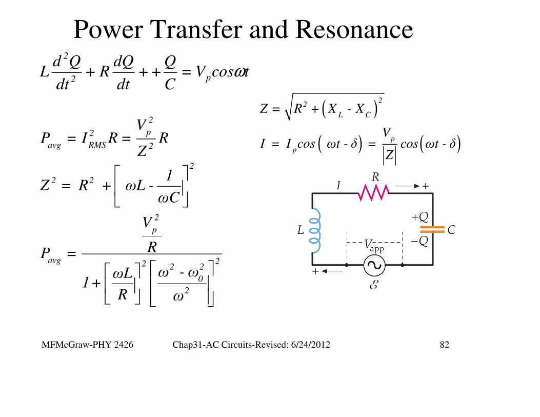
Power Transfer and Resonance
ω2
p2
d Q dQ QL + R ++ = V cos t
dt dt C
( )
( ) ( )
22
L C
p
p
Z = R + X - X
VI = I cos ωt - δ = cos ωt - δ
Z
2
p2
avg RMS 2
2
2 2
2
p
avg 22 2 2
0
2
VP = I R = R
Z
1Z = R + ωL -
ωC
V
RP =
ω -ωωL1+
R ω
MFMcGraw-PHY 2426 Chap31-AC Circuits-Revised: 6/24/2012 83
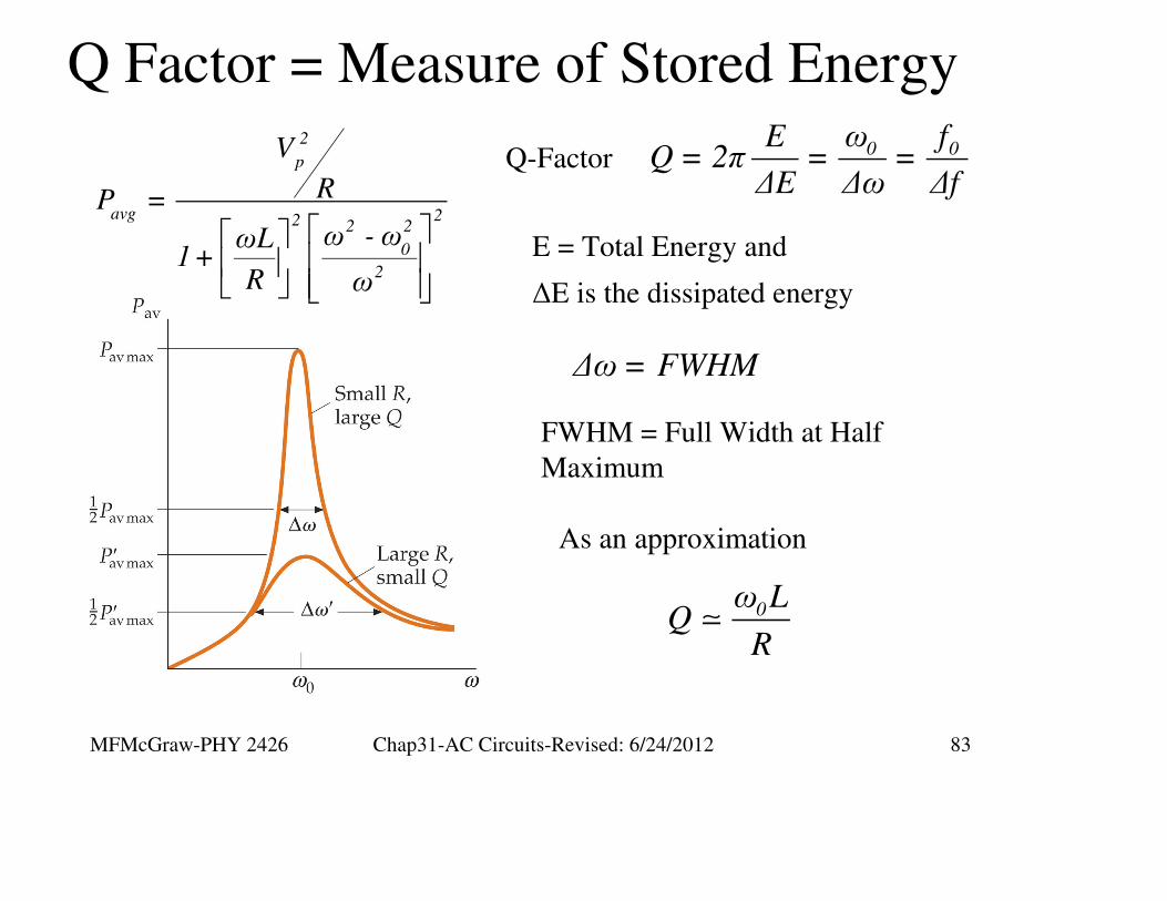
Q Factor = Measure of Stored Energy
2
p
avg 22 2 2
0
2
V
RP =
ω - ωωL1+
R ω
∆ω= FWHM
FWHM = Full Width at Half
Maximum
Q-Factor 0 0ω fEQ = 2π = =
∆E ∆ω ∆f
E = Total Energy and
∆E is the dissipated energy
As an approximation
0ω L
QR
MFMcGraw-PHY 2426 Chap31-AC Circuits-Revised: 6/24/2012 84
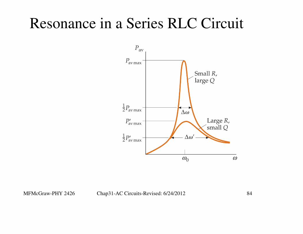
Resonance in a Series RLC Circuit

MFMcGraw-PHY 2426 Chap31-AC Circuits-Revised: 6/24/2012 85
RLC Parallel Circuit
We’re not covering this type of circuit
MFMcGraw-PHY 2426 Chap31-AC Circuits-Revised: 6/24/2012 86
Extra Slides
MFMcGraw-PHY 2426 Chap31-AC Circuits-Revised: 6/24/2012 87
MFMcGraw-PHY 2426 Chap31-AC Circuits-Revised: 6/24/2012 88


