Download - Ch 1
UNIT 1: INDSTRIAL BUILDINGS
Objective
Industrial steel building is a special type of framed structure with one storey height.
These are used for automobile industries, metal industries, thermal power stations,
textile mills, storage, manufacturing units, small scale industries etc. This chapter
deals with the design of the various components of an industrial building.
1.1. INTRODUCTION
Industrial buildings are low rise steel structures that do not normally have interior
floors, walls and partitions. Industrial steel buildings are used for steel plants, metal
industries, thermal power stations, small scale industries etc. The roofing system of
such buildings is a truss with roof covering. The walls are non load bearing but must
be adequately strong to resist lateral forces due to wind or earthquakes. The roof
truss together with the supporting column is called a bent. The length of an industrial
building is divided into bays. A bay is a space between two adjacent bents. The
structural engineer has to consider the following points for the design of the steel
buildings:
1. Structural framing scheme
2. Roof and side cladding material
3. Purlins and sag rods
4. Roof trusses
5. Cranes, columns and base footings
6. Bracing systems
1.2 STRUCTURAL FRAMING SCHEME
A structural framework consists of steel trusses supported over columns making a
transverse bent, and the horizontal bent is formed by joining the transverse bents
(Fig. 1.1).
5

Fig. 1.1 Structural frame of an industrial building
Depending on the need of the industry, the size of various members is adjusted so
that the following requirements are fulfilled:
(a) Adequate horizontal and vertical clearances: Generally, column spacing (bay
length) is kept between 3m to 12m, truss span varies between 6 to 42m, the
height up to crane rail level varies from 4 to 15m.
(b) Sufficient light and greater flexibility for present and future needs: The
requirements of good lighting are its intensity and uniformity. Frequently day
light have to be supplemented by electric lamps to suffice for the
manufacturing process. Whatever source is used the light should be of
uniform intensity without shadows or glare. North light is therefore superior
because it does not admit direct sun and only diffused light enters the
building. Also, for lighting and ventilation of a space where people work, a
window area at least one eighth of the floor area must be provided in the walls
or the roof.
(c) minimum consumption of steel
(d) structurally efficient system
The framing scheme is developed after making a schematic layout of an industrial
building. The steps of structural framing system are:
(i) The column rows are first located according to clearance requirements.
Generally, the column rows at wide distances and with large trusses are
economical than closely spaced columns and short span trusses.
6
(ii) The columns in each row are fixed so that they do not interfere with the
mechanical layout.
(iii) After fixing the column spacing, the pitch of truss is selected and the type of
truss to be provided is decided.
(iv) Provision of sky light, or north light has also to be considered along with. The
resistance of the frames to horizontal loads due to wind and earthquake is an
important point to be decided with regard to the cross section of the building.
(v) The sketch of the members, openings, lintels, doors, windows, girts and an
end wall column is made. Along with this, the plan that shows lateral bracing
system is prepared.
(vi) The material to be used for floor, roof walls, partition walls etc. are decided.
1.3 ROOF AND SIDE CLADDING MATERIAL
For covering roofs and sides of industrial buildings, corrugated iron sheets which are
galvanized for protection against corrosion (popularly called G. I. sheets) are usually
adopted. The most common sizes of sheets are as follows:
1. 8 corrugations 75 mm (3') wide, 19 mm (3/4”) deep; overall corrugated width
66 cm (2'2”), referred to as 8/3 sheets
2. 10 corrugations 75.mm (3”) wide, 19 mm (3/4”) deep; overall corrugated
width 81 cm (2'8”) referred to as 10/3 sheets
Their lengths range from 1.2 to 3 m rising by 0.15 m. When installed side laps and
end laps are to be given to make the joints water proof. Side laps of 1, 1.5 or 2
corrugations equivalent to 50 , 80 and 125 mm (2”, 3.5” and 5") are used in different
situations. For overlapping at the ends, a minimum of 100 mm end lap is given for
side sheeting and a minimum of 150 mm for roof sheeting for slopes of 20° or more
with the horizontal. For Batter slopes, the lap will have to be increased or else
suitable sealing arrangement is to be provided.
The sheets are fastened to purlins by 8 mm diameter hook bolts at maximum pitch of
350 mm. Spacing of supports (purlins and girts) of the sheeting is governed by the
uniformity of sheet lengths, the gauge of the sheet and applied loading. The
maximum spacing may be governed by bending stress or limiting deflecting. The
allowable bending stress in the sheets may be taken 93 N/mm 2 for 24 gauge sheets
7

and 108 N/mm2 for 16gauge. For inter. mediate gauges the value may be
interpolated. The allowable deflection may be taken 1/100 of span for sides. The
allowable deflection of roof sheeting depends on the slope of roof, side_ lap
provided and the intensity of rain. It may be taken 1/150 of span. The allowable
stress and deflection may be increased by 33.5% under wind load and any occasional
concentrated load.
Alternative to the corrugated steel sheets, Asbestos Cement (A. C.) sheets may be
used to cover the roof. These are better insulator of sun's heat which can further be
improved by painting them white on the top surface. A.C. sheets are manufactured in
two shapes, corrugated and trafford as shown in Fig. 1.2 and lengths of 1.52, 1.83,
2.13, 2.44, 2.74 and 3.05 m (5, 6, 7,8, 9 and 10 ft.). The maximum permissible span
is 1.68 m (5'6”). A longitudinal overlap of not less than 150 mm (6”) is provided in
A.C. sheets. A side overlap of one corrugation is usually given. The purlin spacing is
so adjusted with lengths of the sheets that the longitudinal overlaps fall on the
purlins to which they are directly bolted. Spacing of purlins should be so fixed that
the cutting of sheets is avoided.
Fig. 1.2 Asbestos-Cement sheets
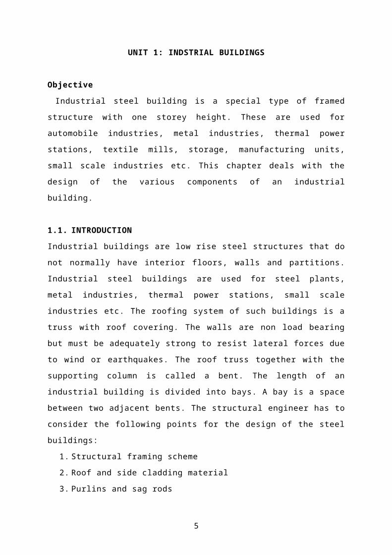
1.4 ROOF TRUSSES
The truss is a framework designed to support roofing and ceiling material over a
large area without intermediate columns. The trusses support the purlins on their
principal rafters and the purlins support the roof covering either directly or through
common rafters and battens. The joints of the truss are assumed to be hinged. The
member forces are determined by simple statics. The point of intersection of two
members is known as nodes or joints and the distance between the nodes is known as
panel length.
The various parts of a roof truss are shown in Fig. 1.3 and the common types which
8

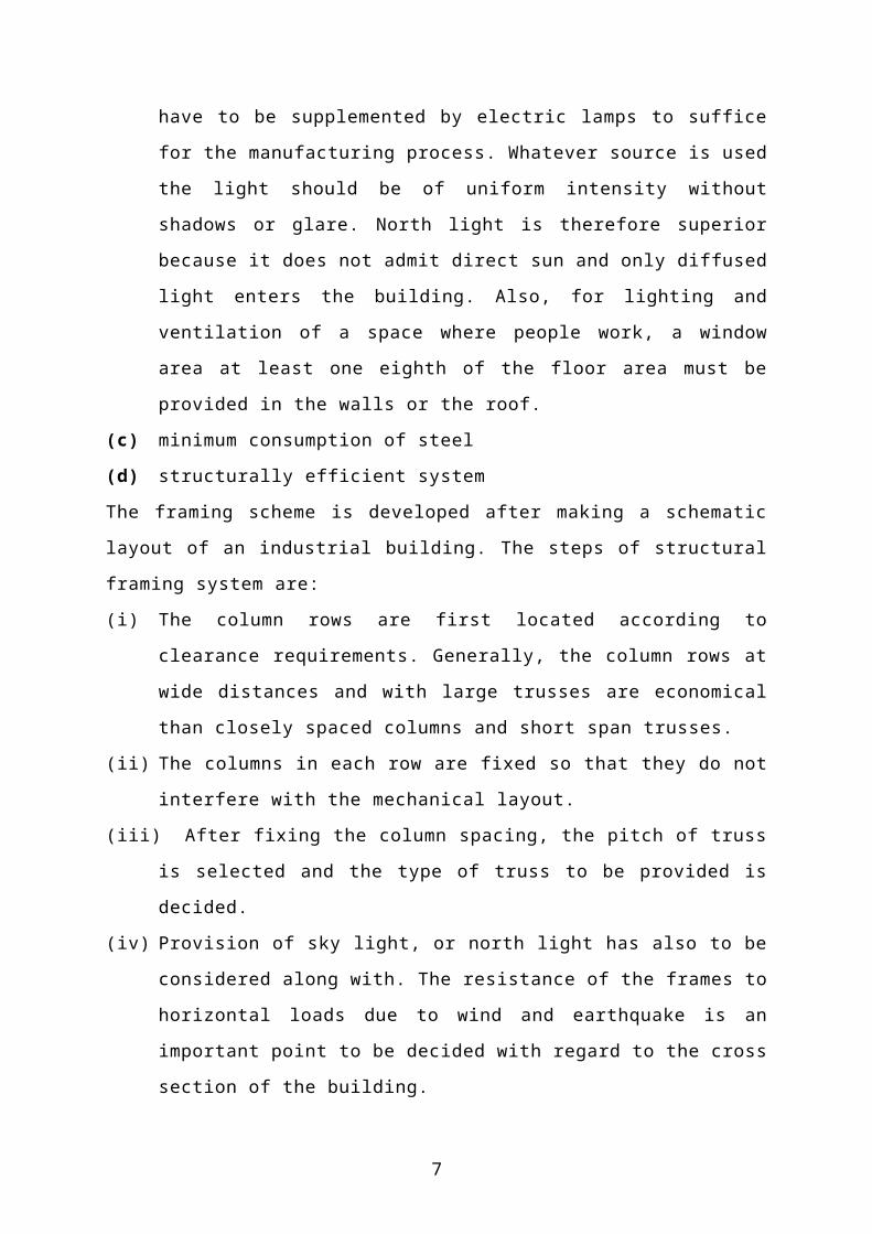
are used in building construction are shown in Fig. 1.4. Suitable spans for the
various trusses are indicated below each type. The truss spacing is usually kept at
1/4th of the span of the truss for shorter spans (up to 15m), and 1/5 th of the span for
15 to 30 m spans. The depth of the truss determines its stiffness in relation to span
and also its economy. A height of 1/6 to 1/5 of span for triangular trusses as stated
earlier, provides sufficient stiffness against light loads.
Fig. 1.3 Parts of a roof truss
Fig. 1.4 Types of roof trusses
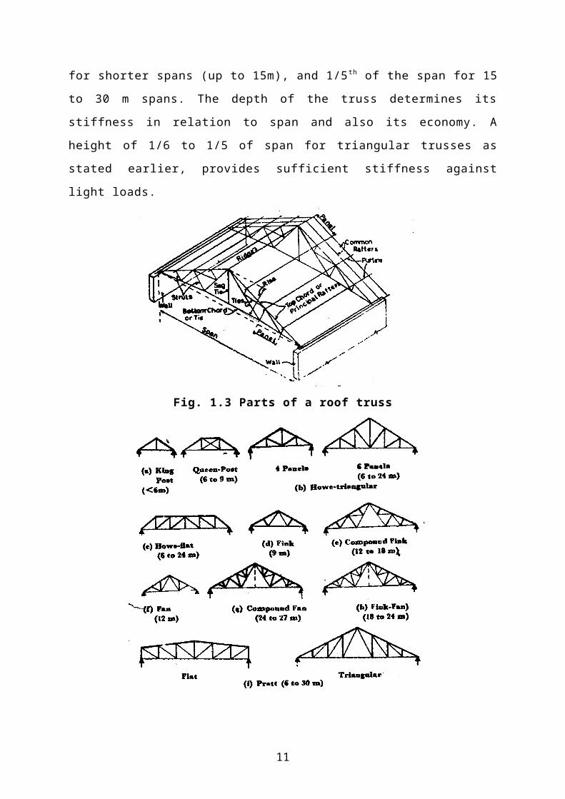
The lower chord of trusses may be left straight or may be cambered (Fig. 1.5).
9

Cambering is done for a better appearance.
Fig. 1.5 Camber of lower chord member
A sag tie is used to reduce the moment due to self weight in the long middle tie
member and hence, helps in reducing tension in that member.
Pitch of Trusses
The pitch of trusses is defined as the ratio of height of the truss to its span. This is
essential to drain off rain water on the sheeted slopes. The minimum recommended
rise of trusses with galvanized iron (G.I.) roof covering is 1/6 and that with asbestos-
cement (A.C.) sheet is 1/12 of span. Where snow fall does not occur, as in most
parts of India, lower pitches upto 1/6 are suitable. Low pitches are advantageous
because the wind pressure on the roof is reduced.
1.4.1 Loads on roof truss:
The roof trusses are subjected to dead load, live load, snow load and wind load.
Dead Loads
The dead loads of the truss include the dead load of roofing material, purlins,
trusses and bracing system. Since the self weights of members to be designed are
not known, they are assumed. Weight of roofing, corrugated sheet or A. C.
sheeting-are almost standard and are prescribed in IS 1911. Purlins are in fact
beams and their weight may be assumed easily and rechecked if necessary. The
dead weight of the truss may be assumed to be equal to 10% of the loads on the
truss. There are number of formulas for weight estimation of roof trusses:
1. w = .02 + .0066 L for live loads of 2.0 kN/m2 (i)
where w = weight of truss in KN/m2
L = span in m. .
If live loads other than 2.0 kN/m2, multiply w by the ratio Live Load per sq. m
2.0
The weight of the bracing may be assumed to be 12 to 15 N/m2 of the plan area.
2. Dead weight of the roof truss in N/m2 is
10
Live loads
The live load on roofs shall be taken as per IS : 875 (Second Revision) Part 2-1987
and is given in Table 1.1.
Table 1.1 Live load
Roof slope Access Live load
≤10º Provided 1.5 kN /m2
Not provided 0.75 kN/m2
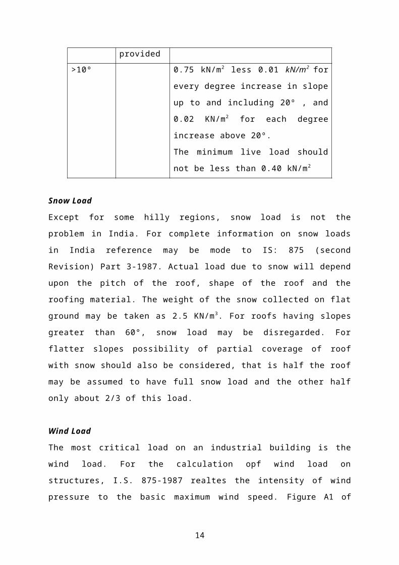
>10º 0.75 kN/m2 less 0.01 kN/m2 for every
degree increase in slope up to and
including 20º , and 0.02 KN/m2 for each
degree increase above 20º.
The minimum live load should not be less
than 0.40 kN/m2
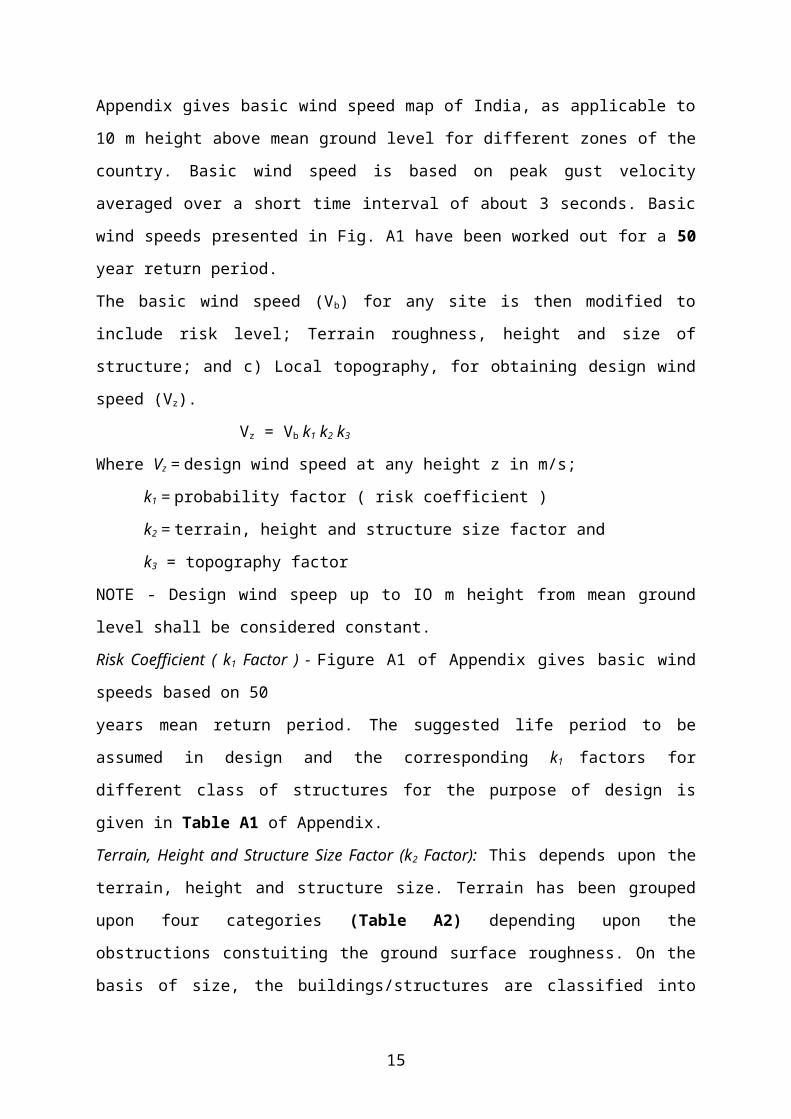
Snow Load
Except for some hilly regions, snow load is not the problem in India. For complete
information on snow loads in India reference may be mode to IS: 875 (second
Revision) Part 3-1987. Actual load due to snow will depend upon the pitch of the
roof, shape of the roof and the roofing material. The weight of the snow collected on
flat ground may be taken as 2.5 KN/m 3. For roofs having slopes greater than 60°,
snow load may be disregarded. For flatter slopes possibility of partial coverage of
roof with snow should also be considered, that is half the roof may be assumed to
have full snow load and the other half only about 2/3 of this load.
Wind Load
The most critical load on an industrial building is the wind load. For the calculation
opf wind load on structures, I.S. 875-1987 realtes the intensity of wind pressure to
the basic maximum wind speed. Figure A1 of Appendix gives basic wind speed map of
India, as applicable to 10 m height above mean ground level for different zones of the
country. Basic wind speed is based on peak gust velocity averaged over a short time interval
of about 3 seconds. Basic wind speeds presented in Fig. A1 have been worked out for a 50
year return period.
11
The basic wind speed (Vb) for any site is then modified to include risk level; Terrain
roughness, height and size of structure; and c) Local topography, for obtaining design wind
speed (Vz).
Vz = Vb k1 k2 k3
Where Vz = design wind speed at any height z in m/s;
k1 = probability factor ( risk coefficient )
k2 = terrain, height and structure size factor and
k3 = topography factor
NOTE - Design wind speep up to IO m height from mean ground level shall be considered
constant.
Risk Coefficient ( k1 Factor ) - Figure A1 of Appendix gives basic wind speeds based on 50
years mean return period. The suggested life period to be assumed in design and the
corresponding k1 factors for different class of structures for the purpose of design is given in
Table A1 of Appendix.
Terrain, Height and Structure Size Factor (k2 Factor): This depends upon the terrain, height
and structure size. Terrain has been grouped upon four categories (Table A2) depending
upon the obstructions constuiting the ground surface roughness. On the basis of size, the
buildings/structures are classified into the following three different classes: Class A -
Structures having maximum dimension ( greatest horizontal or vertical dimension ) less than
20 m; Class B - Structures having maximum dimension between 20 and 50 m; c1ass C -
Structures having maximum dimension greater than 50 m. The design wind speed at different
heigts of the structure can be obtained by multiplying the coefficient k2, given in Table A3,
with the basic wind speed.
Topography ( k3 Factor ) - The basic wind speed Vb given in Fig. A1 takes account of
the general level of site above sea level. This does not allow for local topographic features
such as hills, valleys, cliffs, escarpments, or ridges which can significantly affect wind speed
in their vicinity. The effect is incorporated by factor k3. The value of this factor for level
ground, where the upwind slope is less than 3°, is unity. For slopes greater than 3°, k 3 ranges
from 1 to 1.36.
Design wind pressure: This pressure at any height above mean ground level is given be
pz = 0.6 vz2
where pz = design wind pressure in N/m2 at height z
Design wind force: Wind force on roofs and walls is given by
12

F = (Cpe – Cpi) A pz
Where Cpe = external pressure coefficient
Cpi = internal pressure coefficient
A = surface area of structural member
The average external pressure coefficient for the walls of clad buildings of rectangular plan
shall be as given in Table A4. The average external pressure coefficients for pitched roofs of
rectangular clad building shall be as given in Table A5.
Internal Pressure Coefficients in a building depends upon the degree of permeability of
cladding to the flow of air. The internal air pressure may be positive or negative depending
on the direction of flow of air in relation to openings in the buildings. In the case of buildings
where the claddings permit the flow of air with openings not more than about 5 percent of the
wall area the internal pressure coefficient of ±0.2. Buildings with medium openings between
about 5 to 20 percent of wall area shall be examined for an internal pressure coefficient ±0.5.
Buildings with large openings, larger than 20 percent of the wall area shall be examined with
internal pressure coefficient of ±0.7. In these cases, '+' sign indicates pressure and ‘-'
sign indicates suction.
1.4.2 Load Combinations for Design
The roof trusses should be designed to carry the following combinations of loads
allowing for appropriate permissible stresses:
(a) Dead load + live load or snow load whichever more -use Normal permissible
stresses.
(b) Dead load + wind load, wind direction being normal to ridge or parallel to ridge
whichever is more severe. Use Permissible stresses increased by 331/3% to 50%
depending upon the factor K given in Table 1.2.
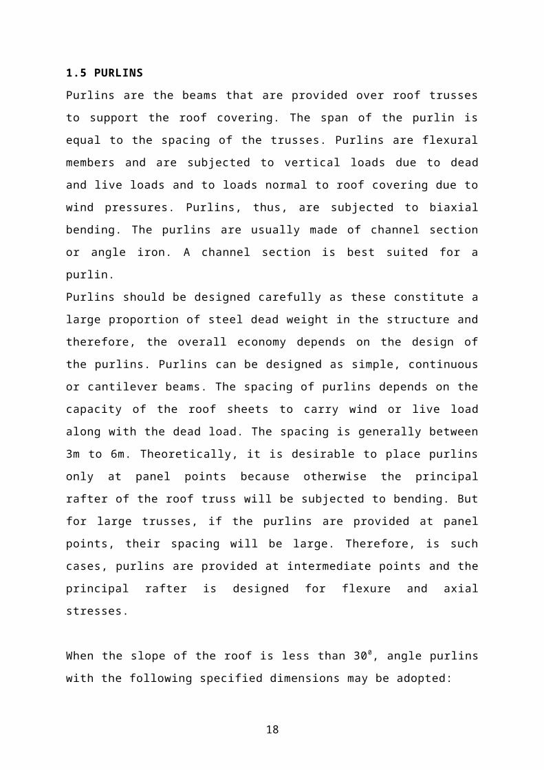
1.5 PURLINS
Purlins are the beams that are provided over roof trusses to support the roof
covering. The span of the purlin is equal to the spacing of the trusses. Purlins are
flexural members and are subjected to vertical loads due to dead and live loads and
to loads normal to roof covering due to wind pressures. Purlins, thus, are subjected
to biaxial bending. The purlins are usually made of channel section or angle iron. A
channel section is best suited for a purlin.
13
Purlins should be designed carefully as these constitute a large proportion of steel
dead weight in the structure and therefore, the overall economy depends on the
design of the purlins. Purlins can be designed as simple, continuous or cantilever
beams. The spacing of purlins depends on the capacity of the roof sheets to carry
wind or live load along with the dead load. The spacing is generally between 3m to
6m. Theoretically, it is desirable to place purlins only at panel points because
otherwise the principal rafter of the roof truss will be subjected to bending. But for
large trusses, if the purlins are provided at panel points, their spacing will be large.
Therefore, is such cases, purlins are provided at intermediate points and the principal
rafter is designed for flexure and axial stresses.
When the slope of the roof is less than 30 0, angle purlins with the following
specified dimensions may be adopted:
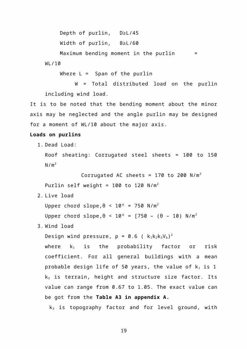
Depth of purlin, D≥L/45
Width of purlin, B≥L/60
Maximum bending moment in the purlin = WL/10
Where L = Span of the purlin
W = Total distributed load on the purlin including wind load.
It is to be noted that the bending moment about the minor axis may be neglected and
the angle purlin may be designed for a moment of WL/10 about the major axis.
Loads on purlins
1. Dead Load:
Roof sheating: Corrugated steel sheets = 100 to 150 N/m 2
Corrugated AC sheets = 170 to 200 N/m2
Purlin self weight = 100 to 120 N/m2
2. Live load
Upper chord slope,θ < 10º = 750 N/m2
Upper chord slope,θ < 10º = [750 – (θ – 10) N/m2
3. Wind load
Design wind pressure, p = 0.6 ( k1k2k3Vb)2
where k1 is the probability factor or risk coefficient. For all general buildings
with a mean probable design life of 50 years, the value of k 1 is 1
k2 is terrain, height and structure size factor. Its value can range from 0.67 to
14
1.05. The exact value can be got from the Table A3 in appendix A.
k3 is topography factor and for level ground, with the upwind slope less than
3°, its value is 1
Vb is the basic wind speed and can be taken from the wind map of India as
given in Appendix A (Figure A1)
Design wind force on the roofs and walls is then given by
Where, is the external pressure coefficients given in Table A4 and Table
A5 for roofs and walls respectively.
is the internal pressure coefficient = ± 0.2
After getting the basic loads, the following load combinations are studied:
1. Dead load + live load
2. Dead load + wind load
1.6 SAG RODS
Purlins have a tendency to sag in the direction of sloping roof. Sag rods are provided
between adjacent purlins to extend lateral support for the purlin in the weaker
direction ad to take up the sag. These are round section rods that are fastened to the
web of the purlin. A sag rod is designed as a tension member to resist the tangential
component of the resultant of the roof load and the purlin dead load. These are
placed at a minimum gauge distance below the top. In general, a single line of sag
rods at the centre of the purlins is sufficient for complete support. The sag rod
should not be terminated at the ridge because in such case, the ridge purline will be
subjected to an excessive pull.
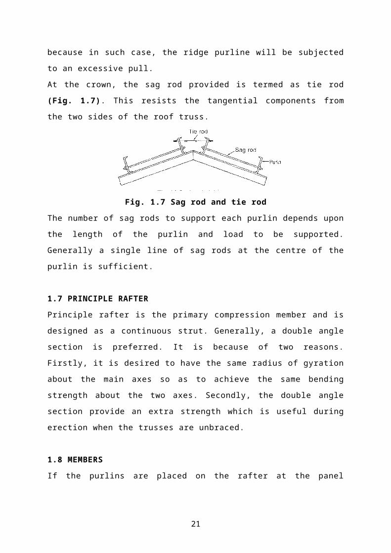
At the crown, the sag rod provided is termed as tie rod (Fig. 1.7). This resists the
tangential components from the two sides of the roof truss.
Fig. 1.7 Sag rod and tie rod
15

The number of sag rods to support each purlin depends upon the length of the purlin
and load to be supported. Generally a single line of sag rods at the centre of the
purlin is sufficient.
1.7 PRINCIPLE RAFTER
Principle rafter is the primary compression member and is designed as a continuous
strut. Generally, a double angle section is preferred. It is because of two reasons.
Firstly, it is desired to have the same radius of gyration about the main axes so as to
achieve the same bending strength about the two axes. Secondly, the double angle
section provide an extra strength which is useful during erection when the trusses are
unbraced.
1.8 MEMBERS
If the purlins are placed on the rafter at the panel points only, there will be no
bending moment in any member and all members will be either a tension member or
a compression member. Single or double angle is used for all members. However, in
some cases, it may not be possible to place the purlins only at the panel points. In
such cases, the rafter will be subjected to bending moment in addition to axial
compression. The rafter is a continuous member and the bending moments will be
computed by the moment distribution method.
The calculations might indicate that very small angles are sufficient for the various
members of the truss, but the members should be fairly stiff to avoid damage during
loading, transport, off-loading and erection. The following minimum sections are
recommended for use in Compound Fink Roof Truss.
Rafters ISA 75 x 50 x 6
Main ties ISA 75 x 50 x 6
Centre tie ISA 65 x 45 X 6
Main sling ISA 65 x 45 x 6
Minor sling ISA 50 x 50 X 6
Main strut ISA 65 x 45 X 6
Minor strut ISA 50 x 50 x 6
Vertical sag tie ISA 50 x 50 x 6
16

The main slings are subject to severe handling stresses and a double angle section
should preferably be used. All other members could be single angle members,
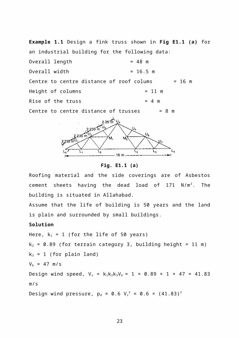
Example 1.1 Design a fink truss shown in Fig E1.1 (a) for an industrial building for
the following data:
Overall length = 48 m
Overall width = 16.5 m
Centre to centre distance of roof colums = 16 m
Height of columns = 11 m
Rise of the truss = 4 m
Centre to centre distance of trusses = 8 m
Fig. E1.1 (a)
Roofing material and the side coverings are of Asbestos cement sheets having the
dead load of 171 N/m2. The building is situated in Allahabad.
Assume that the life of building is 50 years and the land is plain and surrounded by
small buildings.
Solution
Here, k1 = 1 (for the life of 50 years)
k2 = 0.89 (for terrain category 3, building height = 11 m)
k3 = 1 (for plain land)
Vb = 47 m/s
Design wind speed, Vz = k1k2k3Vb = 1 × 0.89 × 1 × 47 = 41.83 m/s
Design wind pressure, pd = 0.6 Vz2 = 0.6 × (41.83)2
= 1049.8 N/m2 or 1.05 KN/m2
Design of Purlins
Let us provide the purlins at the panel points.
17
Design Data
Span of the purlins = c/c distance between roof truss = 8 m
Centre to centre spacing of purlins = 2.235 m
Slope of roof truss = tan -14/8 = 26º34' or 26.566º
Wind load on the roof normal to the roof surface = 1050 N/m 2
Assume dead load of the purlin = 300 N/m
Dead load of A.C. sheets/m = 171 × 2.235 = 382.185 N/m
Total dead load = 682.185 N/m
Live load
Let us assume that no access is provided to the truss. Therefore, for θ = 26.566º
Live load = [750 – 20 × (26.566 – 10)]
= 418.68 N/m2
Total live load = 418.68 × 2.235 Cos 26.566
≈ 880 N/m
Wind load
Height of building column above ground level, h = 11 m
Width of building, w = 16 m
The external air pressure coefficients Cpe can be got from Appendix (Table A4) for the
condition and for θ = 26.566º. Its values are -0.37 for windward side and -0.8
for leeward side.
Let us assume the building to have normal permeability. The internal air pressure
coefficients Cpi are ± 0.02 for the windward and leeward sides.
Wind load = (Cpe – Cpi) pd A
= [-0.8 – (± 0.02)] × 1.05 × 8 × 2.235
= -18.774 KN ≈ 18.8 KN (uplift)
Wind load per unit length of purlin = 18.8/8 = 2.35 KN/m
The wind load will act in the opposite direction to that of the dead load and live
load. Therefore, the effect of dead loads will be reduced by the wind loads. The
critical load for the design of the purlins will be the maximum of
(i) the dead and live loads = 682.185 + 880 = 1562.185 N/m
18
(ii) Difference of wind and dead load = 2350 - 682.185 = 1667.815 N/m
Therefore, maximum bending moment =
For steel with Fy = 240 MPa, Fb = 165 N/mm2
Section modulus =
Minimum depth = L/45 = 8000/45 = 178mm
Minimum width = L/60 = 8000/60 = 133mm
The smallest angle satisfying the above three requirements is ISA 200 x 150 x 12
mm. Check its safety.
The self weight of the section = 318 N/m
Section modulus provided = 117 400 mm3 > 48640 mm3 (safe)
Bending stress,
The assumed dead load was 300 N/m and the dead load of the section provided is 318 N/m.
As the design load is net uplift, the design moment will be reduced slightly. The design is
conservative. Therefore, provide I.S.A. 200 × 150 × 12 mm as the purlin section.
Design of Truss
(i) Dead load
Weight of A.C. sheets = 171 N/m2
Assume weight of bracings = 12 N/m2
Self weight of the roof truss =
Total dead load = 171 + 12 + 110 = 293 N/m2
Assume weight of purlins = 318 N/m
Total dead load of purlins = 318 × 8 = 2544 N
The panel length L0U1 = U1U2 = U2U3 = U3U4 = 2.235 m
The panel length in plan = 2.235 Cos 26.566 = 2 m
Spacing of truss = 8 m
Load on each intermediate panel due to dead load = 293 × 8 × 2 + 2544
= 7232 N ≈ 7.4 KN
Load on end panel points is half of this load = 7.4/2 = 3.7 KN
(ii) Live load
As has been calculated, live load when no access is provided to the roof = 418.68
19

N/m2
The load on each intermediate panel = 418.68 × 8 × 2 = 6699 N ≈ 6.7 KN
The load on each end panel point = 6.7/2 = 3.35 KN
(iii) Wind load
Let us assume the bilding to have normal permeability
Wind load on panel points in windward sides
Wind load = (Cpe – Cpi) pd A
= [-0.37 – (± 0.02)] × 1.05 × 8 × 2.235
= -10.71 KN ≈ -10.8 KN (uplift)
Wind load on each intermediate panel points = -10.8 KN
Wind load on each end panel points = -10.8/2 = -5.4 KN
Wind load on panel points in leeward sides
Wind load = (Cpe – Cpi) pd A
= [-0.8 – (± 0.02)] × 1.05 × 8 × 2.235
= -18.77 KN ≈ -18.8 KN (uplift)
Wind load on each intermediate panel points = -18.8 KN
Wind load on each end panel points = -18.8/2 = -9.4 KN
The design loads for the truss are shown in Fig. E1.1 (b).
For analysis of truss when subjected to dead load and live load, method of joints can
be followed. The resultant stresses are as shown in Table E1.1. For the analysis of
truss when subjected to wind load, the truss is assumed to be hinged at both the
supports. In such a case, the truss becomes indeterminate to the first degree. A small
approximation can be made in this case that the horizontal components of both the
supports are equal to each other. The net forces in all the members can be calculated
by the method of joints.
(i) Dead load at panel points
20
(ii) Live load at panel points
(iii) Wind load
Fig. E1.1 (b) Load Diagram
21

Table E1.1 Stress Analysis
Member Dead
load
stress
(KN)
Live
load
stress
(KN)
Wind load
stress
Maximum stress Design
Force
Wind
left
Wind
right
DL+
LL
DL+LL+WL DL+WL
Rafters
L0U1 -58 -52.5 +95.6 +111.6 -
110.5
-14.9 +53.6 110.5
KN
(C)
63.6
KN
(T)
U1U2 -55.6 -50.3 +95.6 +111.6 -
105.9
-10.3 +56
U2U3 -51.4 -46.5 +95.6 +111.6 -97.9 +13.7 +60.2
U3U4 -48 -43.5 +95.6 +111.6 -91.5 +20.1 +63.6
U4U5 -48 -43.5 +111.6 +95.6 -91.5 +20.1 +63.6
U5U6 -51.4 -46.5 +111.6 +95.6 -97.9 +13.7 +60.2
U6U7 -55.6 -50.3 +111.6 +95.6 -
105.9
-10.3 +56
U7L5 -58 -52.5 +111.6 +95.6 -
110.5
-14.9 +53.6
Main Tie
L0L1 +52 +47 -76 -102.4 +99 +23 -50.4 99.0
KN
(T)
50.4
KN
(C)
L1L2 +45 +40.7 -64 -81.8 +85.7 +21.7 -36.8
L2L3 +31.1 +28.2 -39.8 -39.8 +59.3 +19.5 -8.7
L3L4 +45 +40.7 -81.8 -64 +85.7 +21.7 -36.8
L4L5 +52 +47 -102.4 -76 +99 +23 -50.4
Struts
U1L1 -6.2 -5.6 +10.8 +18.8 -11.8 +7 +12.6 23.6
KN
(C)
25.2
KN
(T)
U2L2 -12.4 -11.2 +21.6 +37.6 -23.6 +14 +25.2
U3M1 -6.6 -6 +10.8 +18.8 -12.6 +6.2 +12.2
U5M2 -6.6 -6 +18.8 +10.8 -12.6 +6.2 +12.2
U6L3 -12.4 -11.2 +37.6 +21.6 -23.6 +14 +25.2
U7L4 -6.2 -5.6 +18.8 +10.8 -11.8 +7 +12.6
22
Minor Sling
U2L1 +7 +6.3 -12.1 -21 +13.3 -7.7 -14 13.3
KN
(T)
15.0
KN
(C)
U2M1 +6 +5.4 -12.1 -21 +11.4 -9.6 -15
U6M2 +6 +5.4 -21 -12.1 +11.4 -9.6 -15
U6L4 +7 +6.3 -21 -12.1 +13.3 -7.7 -14
Main Sling
U4M1 +20.3 +18.4 -36.3 -63 +38.7 -24.3 -42.7 38.7
KN(T)
42.7
KN(C)
L2M1 +13.8 +12.5 -24.2 -42 +26.3 -15.7 -28.2
U4M2 +20.3 +18.4 -63 -36.3 +38.7 -24.3 -42.7
L3M2 +13.8 +12.5 -42 -24.2 +26.3 -15.7 -28.2
Design of members
Main Tie
The main tie is a tension member under constant dead load. However, when the wind
blows, the reversal of stresses occur and the tie is subjected to compressive stresses.
Therefore, primarily it is designed as a tension member and then the section is
checked for compression. While checking it as a compression member, it is treated
as a strut.
Design tensile load = 99 KN
Maximum compression = 50.4 KN
Net area required =
Increase it by 40%
Gross area required = 1.4 × 660 = 924 mm2
Provide 2 unequal angles 65 × 45 × 8 mm, back to back, on the opposite sides of the gusset
plate.
Area provided = 1634 mm2
Use 14 mm rivets for connection.
Net area provided = 1634 – 2 × 8 × 15.5 = 1386 mm2
Safe tensile load = σat × net area provided
= 1.33 × 150 × 1386 = 276,507 N = 276.5 KN > 99 KN (Safe)
23

Check it as a compression member.
Length of the tie between node points, L = 2.498 m ≈ 2.5 m
Effective length, = 0.85 × 2.5 = 2.125 m
Two angle sections are provided for bracing, one at L2 and the other at L3 node in the trusses.
Assuming longitudinal tie at main node points,
Effective length, = 1 × 6 = 6 m
The relevant properties of the built-up section are:
A = 1634 mm2
(elastic critical stress in compression) =
(yield stress of steel) = 250 N/mm2
n = 1.4
= 9.69 N/mm2
Safe compressive load carrying capacity = × area provided
= 1.33 × 9.69 × 1634 = 21058.5 N or 21.05 KN < 50.4
KN
Therefore, the section is not safe.
Revise the section and provide 2 I.S.A. 100 × 65 × 8 mm.
A = 2514 mm2
24
Safe compressive load = 1.33 × 18 × 2514 = 60185 N or 60.18 KN > 50.4 KN (Safe)
Rafter
Panel length, L = 2.235 m
Effective length about xx – axis = 0.85L
= 0.85 × 2.235 = 1.8997 m = 1899.7 mm
The purlins are placed at the panel points. Hence, the length of the rafter between purlins is
equal to the panel length.
Effective length about yy-axis = 1.0 × L = 2.235 m
Design compressive load = 110.5 KN
Provide 65 × 45 × 8 mm. The relevant properties of the section are:
A = 1634 mm2
The slenderness ratio is critical.
For
= 57.567 N/mm2
Safe load carrying capacity = × area provided
= 1.33 × 57.567 × 1634 = 125,105 N or 125.01 KN > 110.5 KN (Safe)
Strut
Design compressive load = 23.6 KN
Tension = 25.2 KN
Length of member = 2.235 m
Let us assume allowable compressive stress = 60 MPa
Area required =
Provide I.S.A. 55 × 55 × 6 mm. The relevant properties of the section are:
A = 626 mm2
25

Safe compressive load = × area provided
= 1.33 × 54.216 × 626 = 45139.16 N or 45.139 KN > 23.6 KN
Check as a tension member
Provide 14 mm diameter rivets.
A1 = area of connected leg =
A2 = area of outstanding leg =
Net area provided = A1 + kA2 = 219 + 0.678 × 312 = 430.54
Safe tensile load = × net area provided
= 1.33 × 150 × 430.54 = 85892.73 N or 85.89 KN > 25.2 KN (Safe)
Minor Sling
Design tensile force = 13.3 KN
Compressive force = 15 KN
Net cross sectional area required =
Gross cross-sectional area required = 1.4 × 88.67 = 124 mm2
Length = 2.48 m
Provide I.S.A. 40 × 40 × 6 mm. The relevant properties of the section are:
A = 447 mm2
Provide 14 mm diameter rivets for connections.
A1 = area of connected leg =
A2 = area of outstanding leg =
26
Net area provided = A1 + kA2 = 129 + 0.635 × 222 = 269.97 mm2
Safe tensile load = × net area provided
= 1.33 × 150 × 269.97 = 53859 N or 53.86 KN > 13.3 KN (Safe)
Check for compression
L = 2.48 m
Safe compressive load = × area provided
= 1.33 × 34.144 × 447 = 20298.95 N or 20.3 KN > 15 KN
Main sling
Design tensile force = 38.7 KN
Compression = 42.7 KN
Length of the member about xx-axis = 2.48 m
Length of the member about yy-axis = 4.96 m
By observation, it is clear that the section will be same as that of the main tie.
Joints
Let us provide 14 mm diameter rivets for connections.
Strength of the rivet in single shear =
Strength of rivet in double shear = 2 × 18.869 = 37.738 KN
Strength of the rivet in bearing over 6 mm = 15.5 × 6 × 300 = 27900 N = 27.9 KN
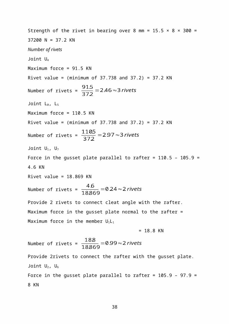
Strength of the rivet in bearing over 8 mm = 15.5 × 8 × 300 = 37200 N = 37.2 KN
Number of rivets
Joint U4
Maximum force = 91.5 KN
Rivet value = (minimum of 37.738 and 37.2) = 37.2 KN
Number of rivets =
27

Joint L0, L5
Maximum force = 110.5 KN
Rivet value = (minimum of 37.738 and 37.2) = 37.2 KN
Number of rivets =
Joint U1, U7
Force in the gusset plate parallel to rafter = 110.5 – 105.9 = 4.6 KN
Rivet value = 18.869 KN
Number of rivets =
Provide 2 rivets to connect cleat angle with the rafter.
Maximum force in the gusset plate normal to the rafter = Maximum force in the member U1-
L1
= 18.8 KN
Number of rivets =
Provide 2rivets to connect the rafter with the gusset plate.
Joint U2, U6
Force in the gusset plate parallel to rafter = 105.9 – 97.9 = 8 KN
Rivet value = 18.869 KN
Number of rivets =
Provide 2 rivets to connect cleat angle with the rafter.
Joint U3 U5
Force in the gusset plate parallel to rafter = 97.9 – 91.5 = 6.4 KN
Rivet value = 18.869 KN
Number of rivets =
Provide 2 rivets to connect cleat angle with the rafter.
Maximum force in the gusset plate normal to the rafter = 18.8 KN
Number of rivets =
Provide 2rivets to connect the rafter with the gusset plate.
Main Tie
28

Joint L0, L5
Maximum force = 99 KN
Rivet value = 37.2 KN
Number of rivets =
Joint L1 L4
Force in the gusset plate parallel to main tie = 99 – 85.7 = 13.3 KN
Rivet value = 37.2 KN
Number of rivets =
Provide 2 rivets.
Joint L2, L3
Force in the gusset plate parallel to main tie = 85.7 – 59.3 = 26.4 KN
Rivet value = 37.2 KN
Number of rivets =
Provide 2 rivets.
Strut
Maximum force = 25.2 KN
Rivet value = 18.869 KN
Number of rivets =
Minor sling
Maximum force = 15 KN
Rivet value = 18.869 KN
Number of rivets =
Main sling
Maximum force = 42.7 KN
Rivet value = 37.2 KN
Number of rivets =
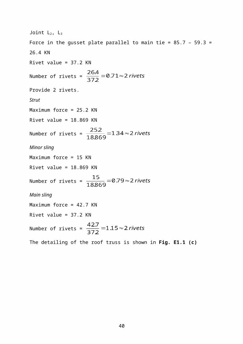
The detailing of the roof truss is shown in Fig. E1.1 (c)
29
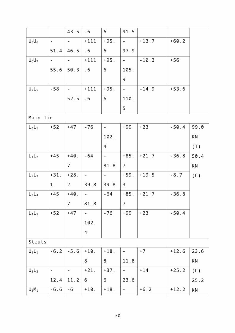
Fig. E1.1 (c) Detailing of roof truss
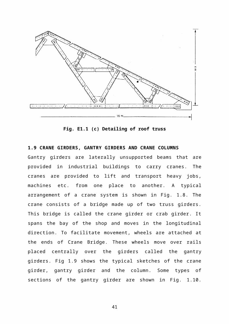
1.9 CRANE GIRDERS, GANTRY GIRDERS AND CRANE COLUMNS
Gantry girders are laterally unsupported beams that are provided in industrial
buildings to carry cranes. The cranes are provided to lift and transport heavy jobs,
machines etc. from one place to another. A typical arrangement of a crane system is
shown in Fig. 1.8. The crane consists of a bridge made up of two truss girders. This
bridge is called the crane girder or crab girder. It spans the bay of the shop and
moves in the longitudinal direction. To facilitate movement, wheels are attached at
the ends of Crane Bridge. These wheels move over rails placed centrally over the
girders called the gantry girders. Fig 1.9 shows the typical sketches of the crane
girder, gantry girder and the column. Some types of sections of the gantry girder are
shown in Fig. 1.10. Since the gantry girder is the major part of industrial buildings,
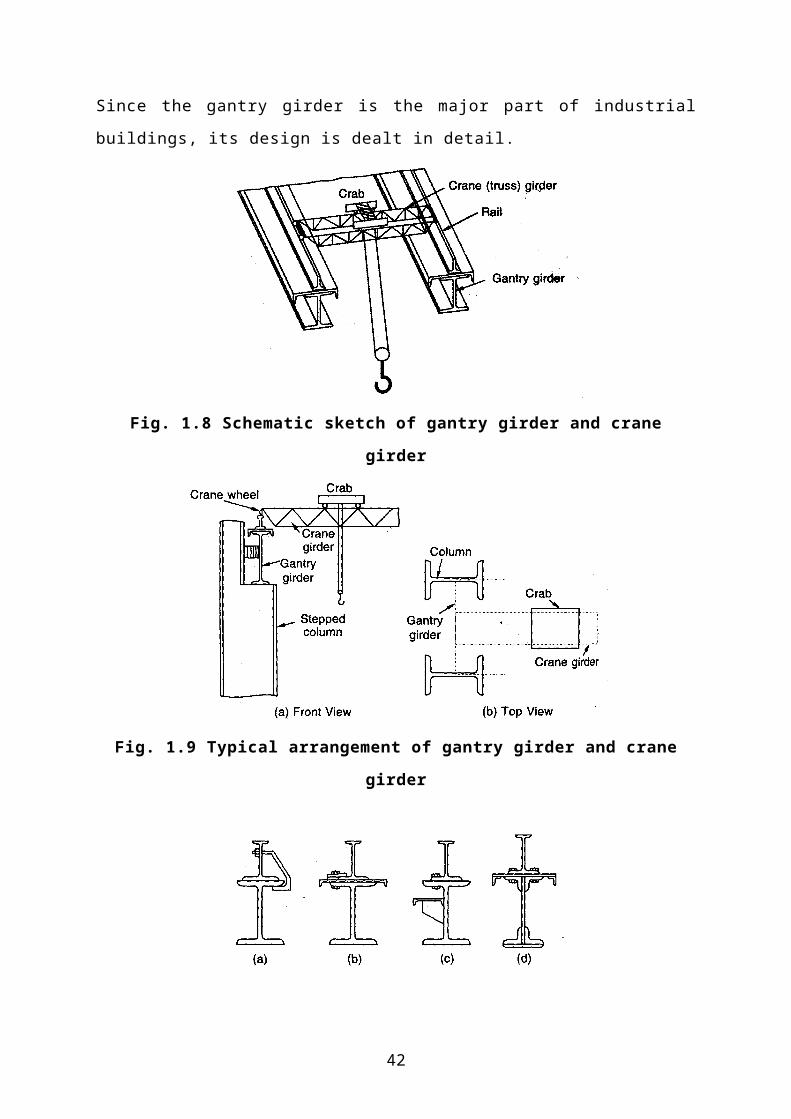
its design is dealt in detail.
30
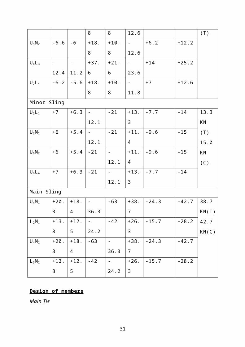
Fig. 1.8 Schematic sketch of gantry girder and crane girder
Fig. 1.9 Typical arrangement of gantry girder and crane girder
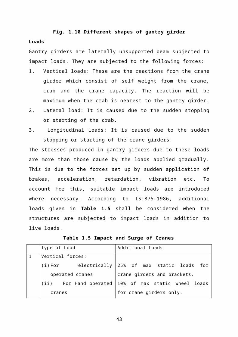
Fig. 1.10 Different shapes of gantry girder
Loads
Gantry girders are laterally unsupported beam subjected to impact loads. They are
subjected to the following forces:
1. Vertical loads: These are the reactions from the crane girder which consist of
self weight from the crane, crab and the crane capacity. The reaction will be
31

maximum when the crab is nearest to the gantry girder.
2. Lateral load: It is caused due to the sudden stopping or starting of the crab.
3. Longitudinal loads: It is caused due to the sudden stopping or starting of the
crane girders.
The stresses produced in gantry girders due to these loads are more than those cause
by the loads applied gradually. This is due to the forces set up by sudden application
of brakes, acceleration, retardation, vibration etc. To account for this, suitable
impact loads are introduced where necessary. According to IS:875-1986, additional
loads given in Table 1.5 shall be considered when the structures are subjected to
impact loads in addition to live loads.
Table 1.5 Impact and Surge of Cranes
Type of Load Additional Loads
1 Vertical forces:
(i) For electrically operated cranes
(ii) For Hand operated cranes
25% of max static loads for crane girders and
brackets.
10% of max static wheel loads for crane
girders only.
2 Horizontal forces:
(i) For electrically operated cranes
(ii) For Hand operated cranes
10% of weight of crab plus weight lifted on
the crab
5% of weight of crab plus weight lifted on the
crab
3 Horizontal forces along rails 5% of all static wheel loads
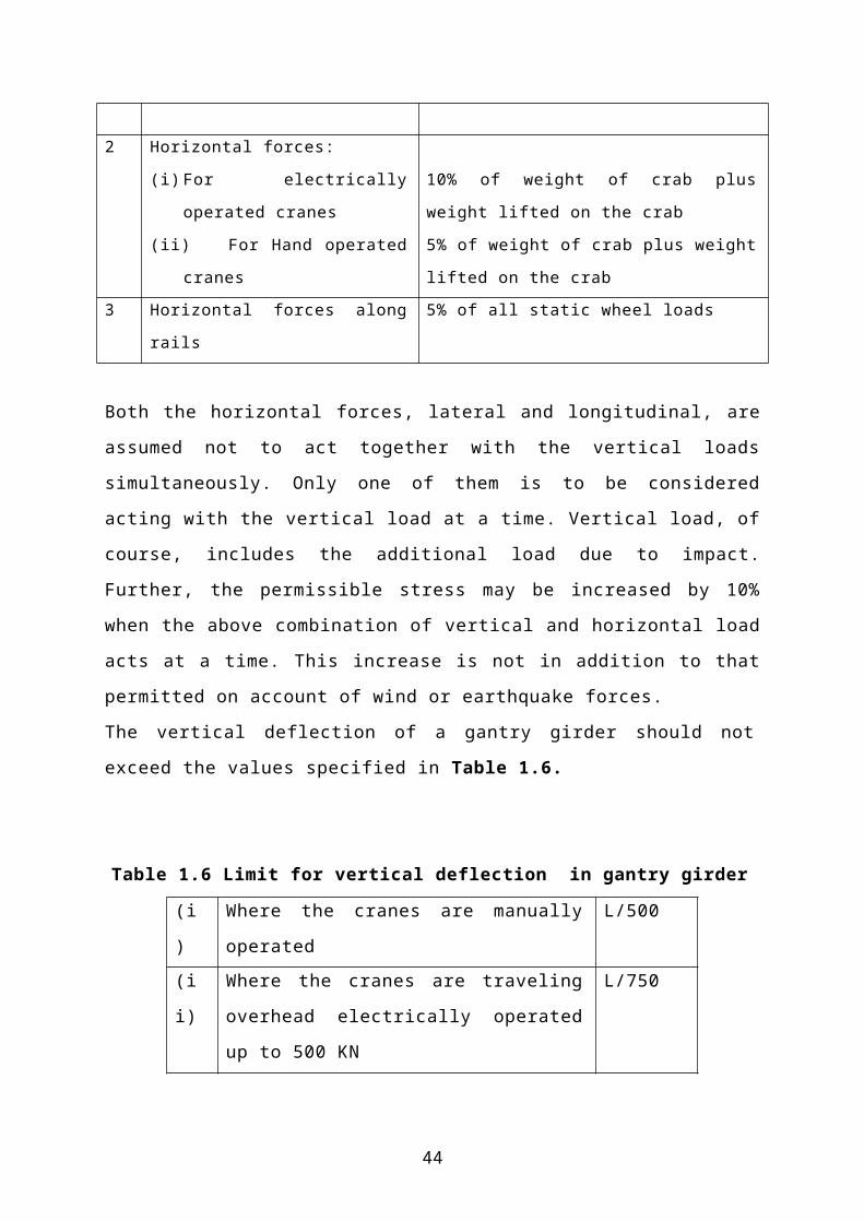
Both the horizontal forces, lateral and longitudinal, are assumed not to act together
with the vertical loads simultaneously. Only one of them is to be considered acting
with the vertical load at a time. Vertical load, of course, includes the additional load
due to impact. Further, the permissible stress may be increased by 10% when the
above combination of vertical and horizontal load acts at a time. This increase is not
in addition to that permitted on account of wind or earthquake forces.
The vertical deflection of a gantry girder should not exceed the values specified in
Table 1.6.
32

Table 1.6 Limit for vertical deflection in gantry girder
(i) Where the cranes are manually operated L/500
(ii) Where the cranes are traveling overhead
electrically operated up to 500 KN
L/750
(iii) Where the cranes are traveling overhead
electrically operated over 500 KN
L/1000
(iv) Other moving loads, such as charging cars L/600
L is the span of the gantry girder
Design of gantry girder
The procedure for design of gantry girder is as follows:
1. Find the maximum wheel load. The wheel load will be maximum when the
crab is closest to the gantry girder. It is in this position that the crab gives
maximum reaction on the gantry girder. The vertical reaction of the crane
girder is transmitted through its two wheels on to the gantry girder. Therefore,
the maximum wheel load is taken as half of the reaction. The maximum wheel
load is further increased for impact as specified in Table 1.5.
2. Find the maximum bending moment due to vertical loads. This consists of the
bending moment due to the dead load of the girder and the rails and the
bending moment due to the maximum wheel loads.
The bending moment due to dead load is maximum at the centre of the span.
The wheel load bending moment is maximum when the two wheels are in such
a position that the centre of gravity of the wheel loads and one of the wheel
loads are equidistant from the centre of the gantry girder. The total moment is
obtained be adding the bending moment due to dead load and the bending
moment due to the wheel loads.
3. Find the maximum shear force. It consists of the shear force due to the dead
load of the gantry girder and the rails and the shear force due to wheel loads.
The shear force due to wheel loads is maximum when one of the wheels is at
the support.
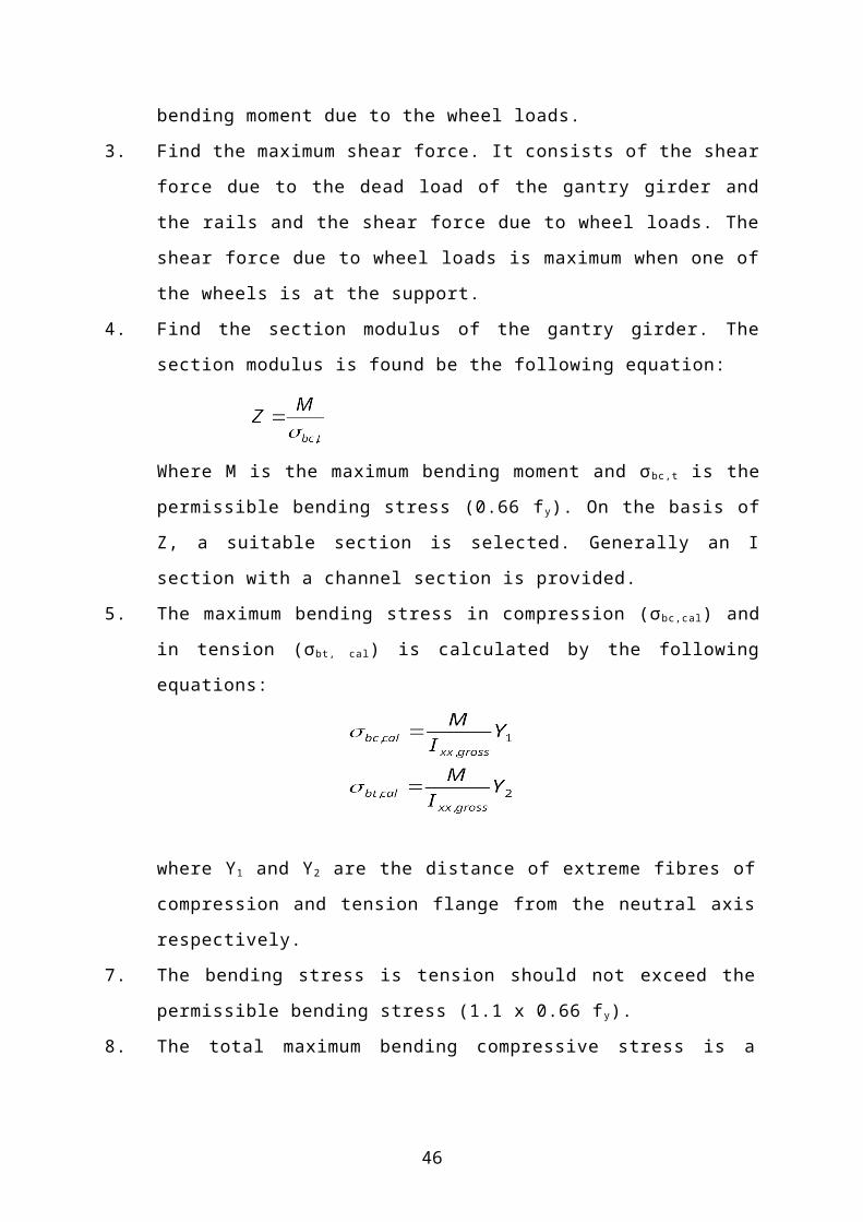
4. Find the section modulus of the gantry girder. The section modulus is found
be the following equation:
33

Where M is the maximum bending moment and σ bc,t is the permissible bending
stress (0.66 fy). On the basis of Z, a suitable section is selected. Generally an I
section with a channel section is provided.
5. The maximum bending stress in compression (σ bc,cal) and in tension (σbt, cal) is
calculated by the following equations:
where Y1 and Y2 are the distance of extreme fibres of compression and
tension flange from the neutral axis respectively.
7. The bending stress is tension should not exceed the permissible bending
stress (1.1 x 0.66 fy).
8. The total maximum bending compressive stress is a combination of the
bending stress due to vertical loads and due to the lateral loads. The bending
stress in compression due to the vertical loads has already been calculated in
step 5. For calculating bending stress due to the lateral loads, the lateral
forces and the maximum bending moments and shear due to these are
calculated. The maximum compressive stress due to lateral loads is then
calculated, assuming that the compression flange takes all the lateral loads.
Hence, the moment of inertia of the compression flange required about its yy
axis is calculated. The total bending stress is found by adding bending
stresses found in step 5 and 8. It should neo exceed the allowable bending
compressive stresses.
9. Rivets connecting the channel to the I-section are designed.
10. The maximum shear stress in the gantry girder is checked.
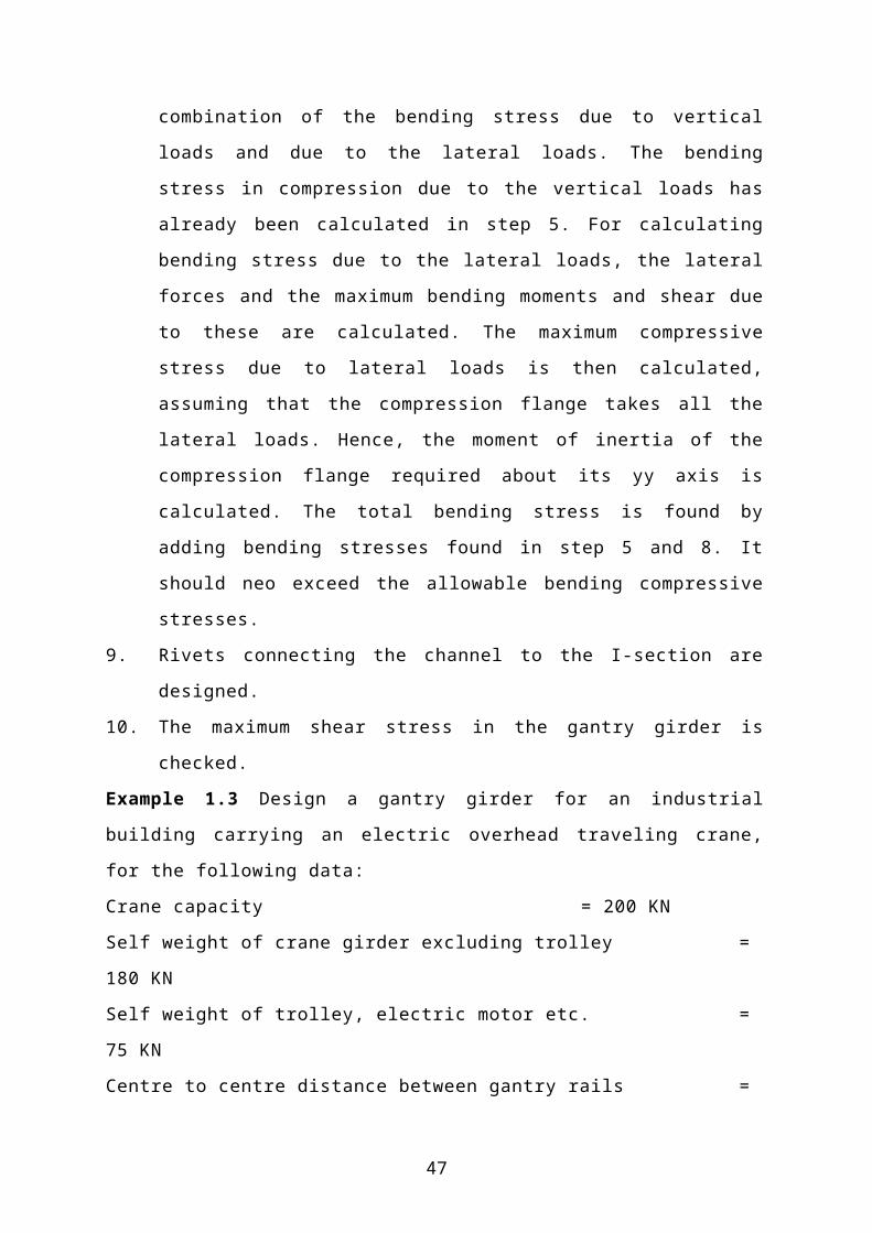
Example 1.3 Design a gantry girder for an industrial building carrying an electric
overhead traveling crane, for the following data:
Crane capacity = 200 KN
Self weight of crane girder excluding trolley = 180 KN
34

Self weight of trolley, electric motor etc. = 75 KN
Centre to centre distance between gantry rails = 20 m
Centre to centre distance between columns = 8 m
Self weight of rail section = 0.3 KN/m
Approach of crane hook to the gantry girder = 1.2 m
Wheel base = 3.5 m
Solution
Step I: Maximum wheel load
Maximum concentrated load on crane = 200 + 75 = 255 KN
The crane will carry self weight as u.d.l. of capacity = 180 / 20 = 9 KN/m
For maximum reaction of the gantry girder, the concentrated load should be placed
on the minimum approach distance of crane hook to the girder. Therefore, the
resultant load position will be as shown in Fig. E1.3(a)
Fig. E1.3(a)
Taking moments about B
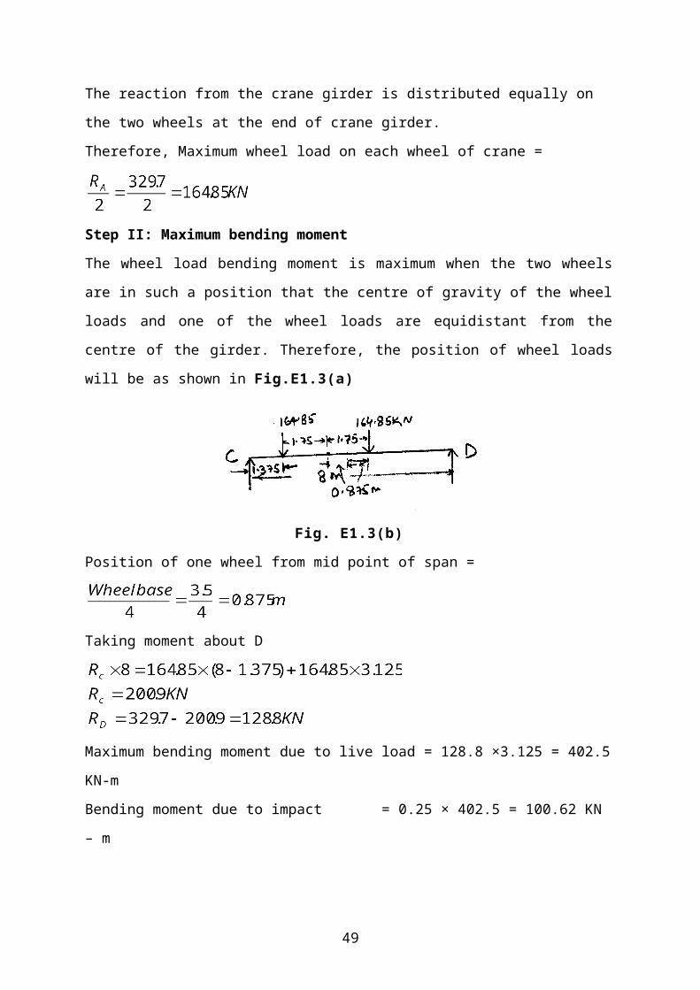
The reaction from the crane girder is distributed equally on the two wheels at the end of crane
girder.
Therefore, Maximum wheel load on each wheel of crane =
Step II: Maximum bending moment
The wheel load bending moment is maximum when the two wheels are in such a position
that the centre of gravity of the wheel loads and one of the wheel loads are equidistant from
the centre of the girder. Therefore, the position of wheel loads will be as shown in
Fig.E1.3(a)
35
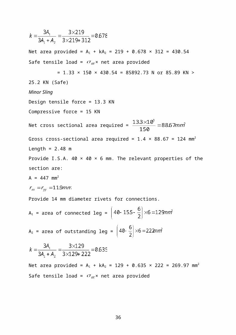
Fig. E1.3(b)
Position of one wheel from mid point of span =
Taking moment about D
Maximum bending moment due to live load = 128.8 ×3.125 = 402.5 KN-m
Bending moment due to impact = 0.25 × 402.5 = 100.62 KN – m
Total bending moment due to live load = 402.5 + 100.62 = 503.125 KN – m
Assume that the self weight of the gantry girder is 2 KN/m
Therefore, total dead load, w = 2000 + 300
= 2300 N/m or 2.3 KN/m
Maximum bending moment due to dead load =
Total bending moment = 503.125 + 18.4
= 521.525 KN-m
Step III – Maximu shear force
The maximum shear force due to wheel load is maximum when one of the wheels is at the
supports. The resultant position of the loads is shown in Fig. E1.3(c)
Fig. E1.3(c)
Taking moment about D
36

Therefore, maximum shear force due to wheel loads = 257.58 × 10³ N
Step IV – Cross section of the gantry girder
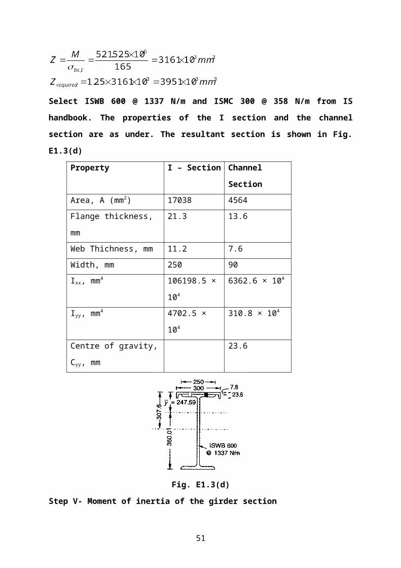
Select ISWB 600 @ 1337 N/m and ISMC 300 @ 358 N/m from IS handbook. The
properties of the I section and the channel section are as under. The resultant section is
shown in Fig. E1.3(d)
Property I – Section Channel Section
Area, A (mm2) 17038 4564
Flange thickness, mm 21.3 13.6
Web Thichness, mm 11.2 7.6
Width, mm 250 90
Ixx, mm4 106198.5 × 104 6362.6 × 104
Iyy, mm4 4702.5 × 104 310.8 × 10⁴
Centre of gravity, Cyy, mm 23.6
Fig. E1.3(d)
Step V- Moment of inertia of the girder section
The distance of neutral axis of the section from the extreme fibre of the compression flange is
Gross moment of inertia of the built-up section
Ixx gross = Ixx beam + Ixx channel
37
In this case, the channel section is placed over the I section in the horizontal position as
shown in Fig. Therefore, yy axis of the channel section becomes the xx axis. Iyy of the
channel section will become Ixx for the build up section
Ixx gross =
Iyy gross = Iyy beam + Iyy channel
= 4702.5 × 104 + 6362.6 × 104
= 11065.1 × 104 mm4
Step VI – Check of bending stresses
Allowable bending stress = 0.66 × fy = 0.66 × 250 = 165 N/mm2
As per IS specifications, the allowable stress is increased by 10 %
Therefore, σbc, t = 1.1 × 165 = 181.5 N/mm2
Step VII- calculation of the bending stress due to lateral loads
Lateral force transverse to the rails = 10% of weight of crab and weight lifted
= 0.1 × 255 = 25.5 KN
Lateral force of each wheel = 25.5/2 = 12.75 KN
Maximum horizontal reaction due to lateral force at C can be calculated by proportion of the
reaction due to vertical loads.
Therefore, Horizontal reaction due to lateral loads, at C
Horizontal reaction due to lateral loads, at D = 25.5 – 15.53 = 9.97 KN
Similarly, bending moment due to lateral force can be calculated by proportion of the value
due to vertical load
Maximum shear force due to lateral loads by proportion
38

Bending stress due to lateral loads is assumed to be taken by the compression flange. Hence,
it I required to calculate the moment of inertia of the compression flange about yy axis.
M.O.I of compression flange about yy-axis = M.O.I of beam flange + M.O.I of channel
= (4702.5/2) × 104 + 6362.6× 104
= 8713.85× 104mm4
Bending compressive stress
Total bending compressive stress = 95.26 + 53.58 = 148.85N/mm2
It should be less than the allowable bending compressive stress
The allowable bending compressive stress can be found from Table 6.2 of IS 800-1984
corresponding to the value of yield stress and elastic critical stress. The elastic critical stress
is given by
Where
k1= a coefficient to allow for reduction in thickness or breadth of flanges between points of
effective lateral restraint, which depends on a ratio ψ
ψ = a ratio of the total area of both flanges at the point of least bending moment to the
corresponding area at the point of greatest bending moment between such points of restraint.
The value of k1 for beams corresponding to ψ is given as under:
Ψ 1 0.9 0.8 0.7 0.6 0.5 0.4 0.3 0.2 0.1 0
k1 1 1 1 0.9 0.8 0.7 0.6 0.5 0.4 0.3 0.2
k2= a coefficient which depends on a ratio ω
ω = a ratio of moment of inertia of the compression flange to the sum of moment of inertia of
both the flanges, each calculated about its own axis, parallel to yy-axis of the girder.
The value of k2 for beams corresponding to ω is given as under:
ω 1 0.9 0.8 0.7 0.6 0.5 0.4 0.3 0.2 0.1 0
k2 0.5 0.4 0.3 0.2 0.1 0 -0.2 -0.4 -0.6 -0.8 -1
39
c1 and c2 are lesser and greater distances respectively of the extreme fibre from the neutral
axis.
In this case,
Ψ = 1, therefore, k1 = 1
dz
Therefore, k2 = 0.28748
Mean thickness of flange, T = 21.3 + 7.6 = 28.9 mm
Overall depth of the girder, D = 600 + 7.6 = 607.6 mm
The values of X any Y can be calculated from the equation given above or it can be found
from Table 6.5 of IS 800-1984 corresponding to D/T and
X = 331.946 N/mm2
Y = 212.77 N/mm2
The value of fcb should be increased by 20 % when T/t < 2
Therefore, value of fcb is not to be increased by 20%
For fcb = 571.62 and fy = 250, σbc from Table 6.2 of IS 800-1984 is
σbc = 135.58 N/mm2
The allowable bending stress is to be increased by 10%
Therefore, permissible bending stress in compression = 1.1 × 135.58 = 149.138 N/mm2
>148.85 N/mm2. Hence safe
Step VIII – Longitudinal forces
40
Longitudinal forces along the rails in the longitudinal direction are calculated. As given in
Table 1.5, it is taken as 5% of the static wheel load.
Let height of the rails = 75 mm
Horizontal force along rails = 5% of the static load
= 164.85 × 0.05 × 2 = 16.48 KN
Bending moment due to longitudinal force = force × distance
= 16.48 × (247.699 + 75) = 5318.69 KN m
Stress in longitudinal direction =
This value is very small, and hence can be neglected.
Step IX – Design of connections
Maximum shear force due to wheel load = 257.58 KN
Shear due to impact = 0.25 × 257.58 = 64.395 KN
Shear due to self weight =
Total shear force = 257.58 + 64.395 + 6.78 = 328.755 KN
Horizontal shear per mm length =
=
Let us use 22 mm dia rivets
Gross diameter = 22 + 1.5 = 23.5 mm
Strength of rivets in single shear =
Strength of rivets in bearing = 23.5 × 7.6 × 300 = 53580 N
Therefore, rivet value = 43373.61 N
Pitch of rivets =
Let us provide the rivets in two rivets in the staggered manner
S = 2 × 321.7 = 643.4 mm 12t = 12 × 7.6 = 91.2 mm
Therefore, provide 22 mm dia rivets @ 90 mm
41
Step X – Check for shear
Average shear stress in web of I-section
, which is safe
Average shear stress in web of channel
, which is safe
1.10 CRANE COLUMNS AND BASE FOOTINGS
The columns that support the gantry girder are called crane columns. They are
normally of three types:
1. Column with brackets (Fig 1.11 a)
2. Stepped column(Fig 1.11 b)
3. Double column (Fig 1.11 c)
Fig. 1.11 Shapes of crane columns
Out of these, a column with bracket is the simplest arrangement which is provided
to support the gantry girder. The crane column is so oriented that it resists fully the
crane load and the moment due to eccentricity of the girder reaction. The crane
columns must be properly braced in the longitudinal direction of the crane girders
42
to be able to take the longitudinal forces due to carne. Such bracing is provided at
every fourth or fifth bay.
The reinforced concrete footing designed as per IS 456 is used as base footing for
industrial columns.
The problem of determining the column load distribution in an industrial building
column is statically indeterminate. To simplify the analysis, the column is isolated
and analyzed as a column subjected to axial load and bending moment.
The industrial column is subjected to the following loads:
1. Dead load from roof truss
2. Live load from roof truss
3. Crane load (dead load of gantry girder, rail, bracket, wheel load and impact
load)
4. Load due to wind.
Analysis
For analysis, it is assumed that the horizontal components of lateral loads are
equally distributed between the points of support of both the bent columns.
Fig. 1.12 Column loads and bending moment diagrams
(i) Column hinged at the base (Fig. 1.12 a)
43
Horizontal reactions, HA = HB =
Vertical reactions, RA = RB =
Where, P = Lateral load
h1 = height of knee brace from foot of the column
h2 = height of the top of the column from the knee brace
L = span of the bent
Let the maximum bending moment is at the knee brace, M =
(ii) Column fixed at the base (Fig. 1.12 b)
Horizontal reactions, HA = HB =
It is assumed that the point of inflextion lies at half the height between the column foot and
knee brace foot,
Vertical reactions, RA = RB =
MB = ME =
(iii) Column partially fixed at base (Fig. 1.12 c)
Horizontal reactions, HA = HB =
As the end fixity is not 100%, the point of inflextion lies below the mid point of the height
between the column foot and knee brace. It is assumed that the point of inflextion lies at 1/3
of the height of the foot of the column to the foot of the knee brace above the foot of column.
Vertical reactions, RA = RB =
B.M. at the foot of the knee, ME =
B.M. at the foot of the column, MB =
1.11 GIRTS
These are beams subjected to unsymmetrical bending. These support vertical loads
44

from the sidings and horizontal wind loads. These are usually angle sections with
the longer leg as the outstanding leg in order to withstand the effect of wind. These
are assumed to be continuous beams with the maximum bending moment as WL/10.
These are bolted to the bent columns and the verticals. (Fig. 1.13)
Fig. 1.13 Girts
Example 1.3 Design girts in an industrial building for the following data:
Height of columns = 11 m
Spacing of roof trusses or spacing of columns = 8 m
Span of truss = 16 m
Intensity of wind pressure = 1.05 KN/m2
Vertical spacing of girts = 1.6 m
Side coverings are of AC sheets with the weight of 171 N/m 2.
Solution
The girts are designed as beams.
Span of girt = spacing of columns = 8 m
Vertical loads
Dead load of asbestos cement sheets = 8 × 1.6 ×171 = 2188.8 N
Let the dead weight of girts = 200 N/m
Therefore, self weight of girt = 200 × 8 = 1600 N
Total vertical load = 2188.8 + 1600 = 3788.8 N ≈ 3800 N
Bending moment in vertical plane =
Horizontal loads
45
From Appendix (Table A5)
For surface C
When θ = 0º; Cpe = -0.5
θ = 90º; Cpe = +0.7
Internal pressure coefficient, Cpi = ± 0.2
Horizontal load due to wind considering the worst condition
P = (0.7 ± 0.2) (8 × 1.6) × 1.05 = 12.1 KN
Bending moment in the horizontal plane =
From IS handbook, use an I.S.A. 150 × 115 × 10 mm section. The relevant properties are:
Stress due to moment in the vertical plane
This stress will occur due to the vertical load on the section as shown in Fig. E1.3
(a)
Maximum bending compressive stress =
Maximum bending tensile stress =
Fig. E1.3
Stress due to moment in the horizontal plane
This stress will occur due to the wind load on the section as shown in Fig. E1.3
(b,c). The wind can blow in any direction, so the stresses can reverse.
Maximum bending (compressive/ tensile) stress =
46
Maximum bending (compressive/ tensile) stress =
The possible combinations are
(i) -29.22 ± 76.82 = -106.04 or 47.6 N/mm2
(ii) -29.22 ±176.82 = -205.66 or 147.22 N/mm2
(iii) 89.4 ± 76.82 = -13.12 or 166.76 N/mm2
The combined stresses should be less than 0.9 fy = 225 N/mm2
Since all the combinations give stresses lesser than the safe stress, the design is safe.
1.12 BRACING SYSTEM
The bracings are provided to increase lateral rigidity of the structure and to transfer
the lateral forces due to wind, earthquake etc. efficiently to the foundation of the
building. Various types of bracings are discussed in the following sections:
Transverse bracings: The transverse bracing is provided in order to reduce the end
moments in the columns. This is achieved either by providing knee braces (Fig. 1.14
a) or by rigid frame portals (Fig. 1.14 b). The rigid frame portals is a welded
structure.
(a) (b)
Fig. 1.14 Transverse bracing
Longitudinal bracing: Wind acting in the longitudinal direction of the building,
that is, normal to the plane of trusses, will require a horizontal truss to transmit the
load to the columns and then a cross frame or bracing in the longitudinal vertical
plane of the columns to transmit the load to the foundations. Fig. 1.15 shows the
bracing system in the plane of the top chord of the roof truss and in the vertical
plane of the longitudinal bent. In this way, every fourth or fifth bay may be braced
but no industrial building should have less than two braced bays.
47

The stresses in the members of the bracing system are small in magnitude and a
nominal section is sufficient to resist the stresses.
Fig. 1.15 Longitudinal bracing in plane of upper chord and column
\
1.13 FRAMING SYSTEM
The behaviour of an industrial bent under lateral loads depends upon two factors.
Firstly, degree of fixidity at the base, and secondly the type of connections between
the column and the truss.
Many different framing arrangements are possible for single storeyed single span
industrial sheds. Fig. 1.16 shows various alternative arrangements.
(e)
Fig. 1.16 Framing for industrial buildings
(i) In Fig. (a), the columns are fixed into foundation and hinged to the truss at
the top. The columns therefore act as free vertical cantilevers and the
foundations are subjected to large bending moments. Such end conditions are
provided when the lateral loads are small and large foundations can be
provided. For example, wide industrial building with smaller height
48
(ii) When the column bending moments due to lateral loads are large, the knee
braces are provided and along with it, the base is fixed (Fig. d). This
arrangement reduces the bending moment at the base and hence, the size of
foundation can be reduced.
(iii) In (b) the fixity has been transferred to the top of columns by providing knee-
braces there and the bottom is hinged. Since the column is hinged at the base,
no bending moment is transferred at the base and the size of foundation can
be reduced further. On the other hand, the truss now carries stresses due to
moments but the foundations are free from it. This frame is statically
indeterminate by one degree.
(iv) The frame at (c) has one knee brace and one hinge at the top. It will make the
frame statically determinate.
(v) When it is not possible to brace the column with knee braces due to clear head
room requirements, then rigid frame portals are provided. In this case, the
bent is made up of a continuous member bent to shape. It is essentially a
welded frame structure.
1.14 ANALYSIS OF TRUSSED BENTS
Most of the frames are statically indeterminate structures and should be analyzed
by the known methods of structural analysis, like slope deflection methods,
moment distribution methods etc. Most commonly, frames with top hinged
columns are used which have single degree of redundancy. Fig. 1.17 shows such a
frame either with brackets as in (a), or having stepped columns as in (b).
Fig. 1.17 Frame hinged at top
The dead load of roof acts axially on the roof legs. But it becomes eccentric on the
column below crane in case (b). The crane load acts on the column ecentrical1y.
Under symmetrical loading, there is no sidesway of the frame, thus the columns act
49

as propped cantilevers carrying a resultant thrust and moment at crane level. This
gives rise to moments and shears in the columns. If the loading is unsymmetrical,
the moments in the columns will be unequal and sidesway will occur. Neglecting
extension or shortening of the truss, the two columns must deflect equally. This
geometrical condition will determine the shears produced in the two columns. The
calculations of deflection involving the stiffness properties of the two columns can
be done by moment area theorems. The relevant information is collected in Table
1.7 for ready reference.
In this table which is zero for a uniform column.
The data is derived by Moment Area theorem for a stepped column and is useful for
finding the distribution of shears in the columns in multi-span frames with trusses
hinged to columns.
Table 1.7 Data for design of columns
Loading condition Reaction at
A, HA
Bending moments
MBA MBC MCB
Deflection Δ at A to left -
Clockwise moment M at B,
no sway
M M -
HA h
Uniform wind pressure p on
full height towards right
Uniform wind pressure p on
height c less than h
Example 1.5 In the industrial shed with the stepped column as shown in Fig 1.17, it is given
that a = 2.4 m, b = 9 m and I2 = 8I1. If the building carries a horizontal wind pressure of 3
KN/m acting on the left column for its full height and the crane reactions are 200 KN and 50
KN on left and right columns acting at eccentricities of 300 mm from the axis of columns,
determine the column moments.
Solution
50
= (0.21)3 (8 – 1) = 0.065
For unit deflection at top of column, the horizontal force required =
Non-sway moments
(a) Left column
(i) Due to wind
HA =
MBA =
MBC = = -20.58 KN-m
MCB =
(ii) Due to crane laod
M = 200 × 0.3 = 60 KN-m clockwise
HA =
MBA =
MBC = M
MCB = 60 – 7.08 × 11.4 = - 20.6 KN-m
(b) Right column – Due to crane load
M = - 50 × 0.3 = - 15 KN
HA =
Sway effect
Total HA = 12.2 + 7.08 = +19.28 KN (towards left)
Total HA’ = -1.77 (towards right)
Out of balance H = +17.51 KN (towards left)
51

To balance this force, the structure must sway to the right, by deflection Δ. For the same
deflection, the unbalanced shear will be distributed to the columns in proportion to their
shear stiffness given by
Stiffness =
In the present case, the two columns are of same stiffness, thus the shear in each column
= -17.51/2 = -8.75 KN (towards right)
Hence sway moments are
Total forces and moments
Effect HA MBA MBC MCB
Wind 12.2 -20.6 -20.6 +55.5 - - - -
Crane 7.08 -17 +43 -20.6 +4.3 -10.8 +5.2 -1.77
Sway -8.75 +21 +21 +100 +21 +21 +100 -8.57
Total +10.53 -16.6 +43.4 +134.9 +25.3 +10.2 +105.2 -10.52
52
EXERCISE
1. Design the fink truss shown in Fig. P1.1 for a span of 18 m and a rise of 3.34 m. This
truss is used at an interval of 5m in an industrial building at Vishakhapatnam in Andra
Pradesh. It is given that 7 mm corrugated sheets ate to be used as roofing. Also design
the purlins that are placed at nodal points of the upper chord.
Assume the building height ratio (h/w) < 12
P1.1
2. Design the fink truss shown in Fig. P1.1 if the purlins are placed at an interval of 1.6
m on the upper chord so that the later is subjected to bending.
3. Design the gantry girder for the following data:
Crane load lift capacity = 200 KN
Weight of crane excluding trolley = 150 KN
Weight of trolley = 75 KN
Centre to centre distance of gantry girder = 20 m
Minimum approach of crane hook = 1.2 m
Distance between centre of crane wheels = 3 m
Span of gantry girder = 6 m
Weight of rail section = 0.3 KN/m
Height of rails = 75 mm
53


