1
CFD modelling of hot machining operation
A thesis submitted in partial fulfilment of the requirements for the degree
of
Bachelor of Technology
in
Mechanical Engineering
by
Mudit Rajput
10603050
Under the guidance of
Prof. Kalipada Maity
Department of Mechanical Engineering
National Institute of Technology Rourkela
Rourkela-769008, Orissa, India
May 2010

2
National Institute of Technology Rourkela
CERTIFICATE
This is to certify that the thesis entitled, “CFD modelling of hot machining operation”
submitted by Mudit Rajput in partial fulfilment of the requirements for the award of the
degree of Bachelor of Technology during session 2009-10 in Mechanical Engineering at
the National Institute of Technology, Rourkela is an authentic work carried out by him
under my supervision and guidance.
And to the best of my knowledge, the matter embodied in the thesis has not been submitted to
any other University/Institute for the award of any Degree or Diploma.
PLACE: NIT Rourkela Prof. Kalipada Maity DATE: 14/05/2010 Professor
Department of Mechanical Engineering
National Institute of Technology
Rourkela – 769008

3
ACKNOWLEDGEMENT
I wish to express my deep sense of gratitude and indebtedness to Prof. Kalipada Maity,
Department of Mechanical Engineering, NIT Rourkela for introducing the present topic and
for his inspiring guidance, valuable suggestions and support throughout this project work.
I am thankful to all my Professors and Lecturers and members of the department for their
generous help in various ways for the completion of the thesis work.
I would like to thank my family members for encouraging me at every stage of this project
work. Last but not least, my sincere thanks to all my friends who have patiently extended all
sorts of help for accomplishing this undertaking.
Mudit Rajput

4
LIST OF FIGURES
CFD interrelation.............................................................................................................figure-1
The interconnectivity function of the three main elements of CFD analysis..................figure-2
Heat transfer coefficient of LPG.....................................................................................figure-3
Modelling with moving mesh concept............................................................................figure-4
Contour and Convergence criteria...................................................................................figure-5
Problem domain for finite element simulation................................................................figure-6
Mesh generation default..................................................................................................figure-7
Temperature distribution.................................................................................................figure-8
Residual of iterations and convergence criteria...............................................................figure-9
Insert rake face temperature..........................................................................................figure-10
Cutting tool insert geometry (SNMG120408 RP KCP10)............................................figure-11
Coating on insert...........................................................................................................figure-12
Tool holder geometry....................................................................................................figure-13

5
Chapter No. Sl.No. Contents Page No.
Chapter 1
1.1 Introduction to Hot Machining 7-8
Materials and preheating methods 8-9
1.2 CFD (Computational fluid dynamics) 9-10
Advantages of CFD 10-11
Navier-Stoke‟s Equations 11-11
Elements of CFD 12-13
Modelling in CFD 13-13
1.3 Introduction to Hard Turning 14-15
Advantages of Hard Turning 15-15
Chapter 2
2.1 Literature Survey of Hot Machining Operation 16-21
2.2 Literature Survey of Hard Turning 22-23
Chapter 3
CFD Modelling of Hot Machining Operation 24-30
Boundary Conditions 31-32
Hard Turning 36-36
Composition of work piece 36-36
Design of experiment 36-36
Tool Insert and Holder 37-39
Chapter 4
Results and Discussions 40-40
Future Works 41-41
References: 42-46
6
Abstract CFD Modelling of Hot-Machining Operation is a machining method conducted on
conventional machine tools in which work piece is preheated before cutting operation to
become softer and thereby to reduce its shear strength. Here in Final Year B.Tech Project
work this work is assigned to me for understanding the Hot-Machining prospects. In our
Work the job to be machined is of High Manganese- Steel. As we know the machining of
these materials has always been a great challenge. Machining of these alloys and materials
requires cutting tool of high strength, which is sometimes not economical and sometimes
even impracticable. And also Non-Conventional processes are generally restricted to
productivity point of view. The benefits of easier manufacturer of the components of
excessive hard materials can be substantial in terms of reduced machined costs and lead time
compared to traditional one involving heat treatment, grinding and manual
finishing/polishing. So for a qualitative and productive process, the growing interest for Hot
Machining Process is being developed in industry.
7
CHAPTER 1
INTRODUCTION
1.1 Introduction
The production of superalloys, high hard and smart materials has become extremely essential
to satisfy the design requirements for critical equipments, aerospace and defence industries.
The machining of such materials has always been a great challenge before the production
engineering. These alloys and materials can be machined by cutting tools of vary high
hardness and strength, but is sometimes neither economical nor practical. Apart from this the
non conventional machining methods are generally restricted due to productivity viewpoint.
The beneficial manufacturing of the components of excessive hard materials can be
substantial in terms of reduced cost of machining and lead time as compared to the traditional
way which involves metal machining in annealed state followed by Heat Treatment, and then
finishing operations like grinding and polishing operations, which in turn consumes lots of
effort, time and workspace. Machining of high hard materials through conventional processes
is restricted due to excessive tool wear of cutting tools and undesired surface finish quality.
So for a qualitative and productive process, the positive interest for hot machining process is
being moderately developed in production technology. The basic of hot machining operation
is to first soften the work piece is by preheating and thereby shear strength gets reduced,
which results in easier machining of materials with many other added advantages.
HOT MACHINING OPERATION:
Hot machining operation is a machining method conducted on conventional machine tools in
which work piece is preheated before cutting operation to become softer and thereby to
reduce its shear strength.

8
As the temperature is increased, the strength of a metal decreases, while the ductility and
plasticity of metal increases. A high temperature is used to provide intense localised heat,
softening only the chip material, leaving the work piece relatively cool and metallurgically
undamaged [1]. The metal becomes soft at higher temperature. High temperature has marked
positive influences on various cutting parameters. Some of the remarkable effects of hot
machining operation are stated as the following:
Life of a cutting tool is more.
Forces required to perform a machining operation are less.
Power consumption is less.
Wear and abrasion of cutting tool is less resulting greater tool life.
Material removal rate (MRR) is high, so high productivity.
Strain hardenability and flow stresses in work piece are reduced.
Better surface quality than conventional routes.
Hot Machining of brittle ceramic materials is very much easier than any other known
approaches.
Previous researches have clearly shown that the above aims are achieved by machining at
elevated temperature. The hot machining process is mainly used for turning and milling
operation. Especially Aerospace, Aviation and Defence Industry follow a lot practice in Hot
Machining Operation.
MATERIALS: The materials which are generally machined by hot machining operation
are hardened steel, NH4 (Ni-hard steel), High Manganese steel, Superalloys, Ceramic
Materials, High Chromium white CI, Cr-Mo white CI, Hyperchrome CI alloys, Stainless
Steel, S-816 alloy, X-alloy, Inconel-X, Timken 16-25-6, Navy Grade Steel, Ni-Cr Steel etc.

9
PREHEATING METHODS: The Hot Machining requires the selection of a suitable
method of heating. The area or zone of heating should be as small as possible. The heating
should not be upto very deep of material in hot machining operation. As at much higher
temperature metallurgical changes occur, so overheating is always undesirable and it must be
avoided. The various modes of preheating the work piece in Hot Machining Operation are:
Flame heating (oxy-acetylene, oxy-LPG flame).
Induction heating.
Plasma heating.
Laser assisted heating.
Electric arc heating.
By radio frequency heating apparatus.
1.2 CFD: Computational fluid dynamics or CFD is the analysis of systems involving heat
transfer, fluid flow and associated phenomenon like chemical reaction by means of computer
based simulation.CFD is a new branch of design engineering which integrates the discipline
of Fluid mechanics/Dynamics with mathematics and also with computer science as shown.
Figure-1 (CFD interrelation).

10
CFD is especially dedicated to the study of fluid in motion and how the fluid flow behaviour
affects processes that may include heat transfer. The ultimate and unique aim of
developments in the CFD fields is to provide a capability comparable to other CAE
(computer aided engineering) tools such as stress analysis codes etc.
The CFD simulation technique is very powerful and it covers a wide range of industrial and
non industrial application areas. Some example and application areas are:
1. Aerodynamics of aircraft and vehicles (lift and drag force analysis)
2. Hydrodynamics of ships.
3. Combustion mechanism in IC engines and power plants.
4. Turbomachinary flows inside rotating passages and diffusers.
5. Chemical process engineering mixing and separation, polymer moulding.
6. Wind loading, heating and ventilation problem.
7. Loads on offshore structure, marine engineering.
8. Hydrology and oceanography (flow in rivers and flood area)
9. Meteorology (weather prediction).
ADVANTAGES OF CFD: There are several unique advantages of CFD over experiment
based approaches to fluid system design.
Substantial reduction in lead times and costs of new designs.
CFD enables us to study systems where controlled experiments are difficult or
impossible to perform (large systems).
CFD provides the environment to study systems under hazardous conditions and
beyond their normal performance limits.
CFD facilitates practically unlimited level of details of results.

11
CFD consists the mathematical basis for a general purpose practical model of fluid flow and
heat transfer from the basic principles of physics. These principles are conservation of mass,
conservation of momentum and conservation of energy. This leads to governing equations of
flows and a discussion of necessary secondary conditions. The key to solution of a problem in
CFD is a set of “ Navier-Stoke‟s equations”.
Navier-Stoke’s equations:
1. Continuity equation (mass conservation)
∂ρ/∂t + div. (ρu) =0
2. X-momentum, Y-momentum and Z-momentum conservation
∂ (ρu)/∂t + div. (ρuv) = -∂P/∂x + div. (µ grad(u)) + SMx (X-direction).
(Similarly for Y and Z).
3. Internal energy (energy conservation)
∂ (ρi)/∂t + div. (ρiu) = -P div.u + div (k gradΓ) + ф + Si.
In order to solve these mathematical equations, they are converted by computer scientists
using high level computer programming languages into programs or software packages. The
computational part simply means the study of the fluid flow through numerical simulation
methods. The market is currently dominated by four CFD codes:
PHOENICS
ANSYS
FLOW 3D
STAR-CD

12
ELEMENTS OF CFD: CFD package consist of 3 main parts.
1. Pre-processor.
2. Solver.
3. Post processor.
PRE-PROCESSOR- pre-processor involves
1) Definition of geometry (computation domain)
2) Grid generation (formation of sub-domain)
3) Selection of physical or chemical phenomenon
4) Fluid property definition
5) Specification of boundary conditions.
SOLVER- There are three different streams of numerical solution technique. Finite
difference, finite element and spectral methods. Basically solver contains numerical methods
that perform following steps:
1) Approximation of unknown flow variables by means of simple functions
2) Discretization
3) Solution of algebraic equations
POST PROCESSOR- Post processor includes the geometry of domain of problem and
display, the vector plots, 2D-3D surface plots, coloured postscript output and animation for
dynamic result display.

13
Fig.-2(The interconnectivity function of the three main elements of CFD analysis) [2]
Modelling in CFD: It basically consists 2 parts
1) Design in GAMBIT
2) FLUENT SOLVER
DESIGN IN GAMBIT- Geometry Selection
Meshing
Boundary conditions
FLUENT SOLVER- Apply properties of materials
Steady/Unsteady condition
Energy Equation
Initialization
Iteration and Display.

14
1.3 INTRODUCTION TO HARD TURNING:
Today the recent trends in manufacturing industries is to strive for lower cost solution
techniques while maintaining the quality level within acceptable limits along with lowest
setup and lead time due to the competitiveness in market. So attention is towards developing
the technology to meet such requirements. The newer solution to this trend is a hard turning
process, which is best operated with suitably configured lathe turning centres.
Hard turning is a metal machining process with the single point cutting tool (i.e turning
carried out on lathe machine tool) carried out on "hard" materials. Here "hard" material is
defined as the material having hardness of grade Rockwell‟C‟ greater than 45 but more
typically in range of 58-68 HRC [3]. Generally the parts are first undergone through the heat
treatment process and then Hard Turning is performed. Hard Turning is almost similar and
simpler as a simple turning process on a lathe but the main difference is the selection of
special tools and cutting variables and the rigidity of machine tools.
Hard turning process is intended to skip or limit the conventional grinding operations that are
not cost effective, environment friendly and flexible. Hard turning, when intended for purely
rough turning purposes, competes favourably with rough grinding. However, grinding is
better for finishing operation where form and dimensions are critical. A better dimensional
accuracy of roundness and cylindricity is achieved in grinding process. A roundness accuracy
of 0.5-12 microns, and/or surface roughness of Rz 0.8-Rz 7.0 microns can be best achieved
by hard turning alone. [4]
The tooling in the hard turning process is key to achieve the desired objectives. The Ceramic
tools, Cermets, and Cubic Boron Nitride (CBN) are the typical tools used in hard turning
process. CBN is the predominant choice among hard turning tools. CBN sometimes enables

15
to skip the grinding process completely in particular cases. Facts showed that in year 2001 the
CBN tools sales crossed $250 million, which provides an idea about the broad and frequent
use of this technology [4]. CBN tools offer a higher flexibility and allow dry machining
eliminating the use of coolants. Manufacturing cost cut, decreased lead time and overall
improved part/product quality can often be achieved by hard turning process with ceramic
and CBN tools.
Hard turning is generally used for manufacturing of gears, roller bearings, automotive
components and injection pump components, components of hydraulic machinery and among
other applications.
Advantages of hard turning technologies:
4 to 6 times higher MRR (Metal removal rates) with hard turning process are achieved
than equivalent grinding operations.
Hard turning tooling inventory is quite low as compared to grinding wheels
inventory. Moreover, the existing tool holders used for multitudes of operations also
permit the use of CBN inserts with them.
Hard turning technology is an environment friendly approach as the CBN and ceramic
tools allow a dry cutting possibility, which also contributes the method to be more
economical.
Low micro-inch finishes is possible to be achieved in hard turning. Surface finishes
within the range of .0001 mm to .0004 mm are very common.
Hard turning technology does not require to meet the use of a different machine tool.
Infact lathe offers versatility of hard turning operation along with soft turning
operation on the same machine tool.
16
CHAPTER 2
LITERATURE SURVEY
This chapter enlightens some of the recent remarkable and important researches and report
studies published in literature on Hot Machining and Hard Turning processes. This chapter
includes the results and capabilities so far achieved by the Hot Machining and Hard Turning
processes.
2.1 Literature survey on HOT MACHINING OPERATION:
So far the main aim of the studies conducted on Hot Machining operation is to investigate the
effects of the various experimental and cutting variables on the product quality, process
reliability and tool wear phenomenon. Studies have helped the engineers to optimize the
process variables to achieve the best results. The following criteria is generally followed
while Hot Machining Operation.
Variables to be altered:
Rotational speed
Cutting speed
Depth of cut
Feed
Surface temperature
17
Effects to be analyzed:
Cutting forces
Tool wear
Surface finish/roughness
Chip thickness
Temperature and stress distribution
Optimum parameters give:
Minimum surface roughness.
Minimum sub-surface defects.
Minimum tool wear or minimum cost.
Maximum metal removal rate (MRR).
Maximum precision and accuracy.
Tigham known as the innovator of Hot Machining first conducted experiment on hot
machining. In 1949-1951 various experimental works were done by Tour and Fletcher,
Schmidt and Robik. They processed stainless steel, X-alloy, Inconel-X, Timken and Navy-V
grade steel through hot machining operation. In 1951, Merchant, Krabacher and Shaw
conducted experiments on hot machining. They obtained the results of tool life raising and
reduced hardenability and flow stresses. In 1973, mukherjee and Basu conducted hot
machining of Ni-Cr steel and concluded that cutting speed, feed, depth of cut and workpiece
temperature influenced the tool life as well as surface finish. In 1988, plasma hot machining
was first conducted by Meakawa and Kubo. Ozler used gas flame heating in 2000 during his
experiment. Literature has shown that so far hot machining is limited only to turning and
milling processes. [5-9]
18
Wang et al [10] reported the benefits of hybrid machining of Nickel base Inconel 718 alloys.
N.Tosun and Ozler [11,12] used hot machining technique in turning operation. The
optimization of the turning operation with multiple performance characteristics, tool life and
workpiece surface roughness, was studied using weighted factor to improve the tool life and
the workpiece surface roughness. The parameter design method proposed by Taguchi was
adopted. Experimental results obtained, when cutting high manganese steel heated with the
liquid petroleum gas (LPG) flam, were presented. They improved the approach proposed. K.P
Maity and swain [13] invested hot-machining operation of high manganese steel using flam
heating. A tool life equation has been developed from their statistical analysis. These were
some of the remarkable work done in hot machining operation.
Generally the materials which are hot machined are classified into four categories as per their
composition and hardness property. These classes are the following:
Chilled cast iron,
Steel with hardness over 50 HRc,
Steels those surface is hardened with cobalt, other and additions alloy,
Steels hardened by cold working (e.g. high manganese steel).
The selection of an ideal method of preheating of metals for machining is very critical. An
improper heating method is a strong reason to create unwanted structural changes in the
workpiece and it may also be responsible to increase the overall cost of product. Researchers
have opted for many heating methods, [9]. Electrical resistance and plasma arc heating are
however most commonly utilized heating techniques. However, other methods are also used

19
[9,10]. (frm high manganese). Gas flame heating is also an economical approach of
preheating.
Detailed study from literatures:
The more and more attention is paid to achieve a much better tool life in hot machining
operation. Researchers have developed a number of tool life equations which correlates the
tool life with experimental and cutting variables.
Ozler and Ozel[5] conducted hot machining operation on austenitic manganese steel. They
utilized liquefied petroleum gas and oxygen gas mixture to preheat the metal. Both theoretical
and experimental determination of tool life was carried out. A number of feed rate, cutting
speed and surface temperature were chosen for experiment conditions. Results from their
experiments has enlightened the following facts.(from high manganese steel).
While cutting at room temperature the tool life was found to decrease rapidly as the
cutting speed was increased upto 46 m/min. At speeds higher than 46 m/min the
decrement in tool life was slower.
The longest tool lives were determined at a speed of 22 m/min for both conditions of
cutting at room temperature and at elevated temperature. The reduction in resistance
at chip-tool interface at smaller values of cutting speed was found the reason behind
the longer tool lives.
The results and data‟s have also indicated that as the temperature is increased,
resistance to cutting is decreased, magnitudes of cutting force were less and lesser tool
wear, hence longer tool life was observed.
20
In contrast of the hot machining in recent years a lot of experiments and researches have been
carried out to determine the benefits and effects of “LASER ASSISTED HOT
MACHINING”. More work associated with laser assisted machining has been found limited
upto the machining of brittle ceramics only. In Laser assisted machining (LAM), the laser
technology is combined with conventional turning and milling process. A small laser spot
diameter and a power/heat density of up to 106W/cm2 provides the high power, localised
heat source required for laser assisted machining [14]. A high power density laser beam is
directly focussed on the workpiece just in front of the cutting tool. The heat from laser beam
softens the primary shear zone along which the chips start to shear.
Rozzi et al. [15] conducted laser assisted hot machining experiments on silicon nitride
ceramic and investigated the reduction in magnitudes of cutting forces due to reduction in
strength which permits viscous-elastic flow, due to which the friction between the tool face
and the material gets reduced. Rozzi also determined that during laser assisted machining
93% of energy by added by laser beam and only 7% was contributed by cutting process.
Rozzi also concluded that during laser assisted machining the specific cutting energy is
significantly lower even than the grinding process which is the only route to finishing of
ceramics. This study clarifies the logic that during laser assisted machining, the heat
generated by the cutting tool will be reduced.
Various other heating methods are also employed in hot machining operation. But every
method has some limitations, so their applications are few and particularly more specific. For
example Laser Assisted Machining has very low efficiency and also the equipments for laser
assisted machining are extremely expensive. Electron beam heating is also expensive due to
the need of vacuum space while machining. So the break through has been achieved by

21
PLASMA ARC HOT MACHINING PROCESS, which not only discards various
disadvantages like cost, metallurgical/structural damage to the workpiece, but also results
better surface finish, higher productivity and longer tool life.
A plasma arc consists of a high velocity, high temperature stream of ionized gas capable of
supporting a high-current, low-voltage electric arc. A plasma arc is created by the ionisation
of gases in copper nozzle. The arc characteristics and reliability of arc striking are improved
with the balanced geometry of the nozzle orifice. Temperature within the arc has been
reported to be in the range of 16,000 °C to 30,000 °C. The plasma assisted hot machining
process has proved itself as a tool for high production rates and machining of rough forgings.
Plasma assisted hot machining is most suitable for interrupted cuts. This process is currently
being in state of adoption at BHEL (Bharat Heavy Electronics Ltd., tech & development Lab,
Hyderabad).[16]
The ELECTRIC HOT MACHINING is a technique of hot machining in which the
workpiece is heated by electric current which flows through the cutting point. Electric
resistance hot machining has a substantial advantage, that is, the electrically heated zone
coincides with the deforming zone of the cutting. Electric hot machining could be applied to
various machining such as turning, drilling etc. without remarkable temperature rise of
machined surfaces. By means of this heating method, stainless steel, chilled cast iron and
Hadfield steel were turned with various tool materials, and cutting characteristics including
tool wear, surface roughness and machine vibrations were measured. Kunio, Misturu found
that the coated carbide tools exhibits a good cutting performance especially on the tool wear,
and it is verified that the cause of this phenomenon is due to low electric resistance of base
metal of the coated tools and high wear resistance of the coated layers. [17]

22
2.2 Literature survey on HARD TURNING:
The high hardness of high chromium white cast irons makes them highly abrasive wear
resistant materials. This makes them difficult and expensive to machine. The abrasive wear
resistant material drastically reduces the life of ceramic and tungsten carbide tools making
them ineffective in cutting it. They are currently machined by a method known as hard
turning. Hard turning incorporates high cutting speeds and cubic boron nitride (CBN) tools
and is used in situations where the more common ceramic coated and tungsten carbide tools
are not effective. CBN tools have been commercially available now since the 1970‟s and they
have brought a great change in hard machining technology because of their many favourable
properties [18]. CBN has hardness and wear durability second only to diamond and it has
good thermal resistance, a high coefficient of thermal conductivity and high hot hardness
[19]. A negative rake angle, high speeds and no coolant cause the temperature in the small
cutting zone to rise to temperatures above 900°C [18-22]. Ng et al. [23] has stated that
“During metal cutting heat is generated in the primary shear zone and the secondary
deformation zone” of the materials being cut. The high temperatures reduce the shear stress
in the primary shear zone reducing cutting forces. The majority of heat generated is removed
in the chip. However, this is to the detriment of the tool wear [18]. During hard turning a
negative rake angle is used as the chamfered edge gives greater strength to brittle CBN tools
[18].
Ng and Aspinwall [25] measured the cutting forces generated by CBN tools on bars of AISI
H13 hot work die steel heat treated to various hardness values (28, 35, 42 and 49 HRC) and
cut at various speeds.A general perception among various researchers is that the surface
roughness produces during hard turning by CBN tools is generally acceptable. During hard
turning feed rate has the greatest effect on tool wear and surface roughness. The negative rake
23
angle CBN tools generate lesser magnitude of cutting forces during hard turning than the
forces generated by positive rake angle tools because of small chip tool contact length and the
small plastic deformation of the tool.
The rigidity of the machine tool is definitely main issue while had turning process. Hard
turning with CBN tools demands of a very rigid, high precision and high horse power
machine tool. Lack of rigidity of machine tool leads to increased tool wear due to chipping
because of brittle nature of tool. Like the carbides, the CBN cutting tools are also available in
several grades and they must be chosen properly as per the requirements. For example: A low
content CBN insert will not perform well in an interrupted cutting application because it lacks
the necessary toughness. Generally, high content CBN inserts have higher toughness whereas
low content inserts provide longer tool life in straight turning applications.
Material types for hard turning applications make a long list. Commonly processed materials
by hard turning would include all grades of hardened steel alloys such as bearing steels, hot
and cold-work tool steels, high-speed steels, die steels and case hardened steels. Inconel,
Hastelloy, Stellite and carburized and nitrided irons along with some coatings like high
chrome can also be serious materials for this process. Successful hard turning depends upon
the entire machining system and not just certain discrete elements.As a way of summary, the
following items all relate to successful hard turning applications.
A machine with a high dynamic stiffness and rigidity.
Efficient workholding devices.
A correctly chosen CBN grade or other tooling material type.
High quality cutting edges.
Rigid tool mounts.
Appropriate machining parameters.
Part piece rigidity.

24
CHAPTER 3
CFD MODELLING OF HOT MACHINING OPERATION
This chapter describes the methodology and modelling procedure in CFD of Hot Machining
Operation.
3.1 PROBLEM STATEMENT:
A cylindrical workpiece of 50mm diameter and 500mm length is rotated in a turning centre at
400 rpm. The workpiece is heated constantly with a moving heat source which is a flame
(LPG+ O2). We have to design a model in CFD and to do analysis to find out temperature
distribution of the tool, chip and work piece. The surface temperature of workpiece at contact
of flame is 5000C.
Workpiece material= High manganese steel,
Rotational speed N= 400 rpm,
Workpiece length= 500 mm,
Workpiece diameter= 50mm,
Feed = 0.1 mm/rev,
Flame travel= 0.1 mm/rev.
Flame temperature= 5000C.
Composition of High Manganese steel:
Metal Mn C Si Cr P S Fe
% 12.5 1.2 4 1.6 0.058 0.01 84.23

25
Work material properties:
Work material Density
(Kg/mm3)
Specific heat
(J/Kg-K)
Thermal
conductivity(W/mm-k)
High Manganese Steel 7.8×10⁻⁶
Cp= 420+ 0.67T 0.05
Tool Insert properties:
A carbide tool with specification ATP ISO (M10) was used. The tool had the following
geometrical and physical characteristics:
Side rake angle = 4.6250◦.
Back rake angle = 0.925◦.
Orthogonal clearance angle = 9.7◦.
Orthogonal rake angle = 5.2◦.
Density = 12×10-6
Kg/mm3.
Thermal conductivity = 0.045 W/mm-K
Specific Heat = 250 J/Kg-K
Convective heat transfer coefficient of LPG+O2 gas with air depends upon moisture content
of air. A variation of heat transfer coefficient of liquefied petroleum gas (LPG) with air [28]
is shown in following plot.

26
Figure 3- (heat transfer coefficient of LPG) [28]
Following the observations of above plot we can assume the heat transfer coefficient of PLG
to be near about 180 W/m2-
0C.
The first law of thermodynamics states, “when work is transformed into heat, the quantity of
work is equivalent to the heat produced.” This heat will be generated when conversion of
mechanical energy takes place. The main sources of heat in metal cutting mechanism are
basically three distinct heat sources.
1. The shear zone, Q1, where the main plastic deformation takes place.
2. The chip-tool interface zone (or say the rake face of cutting tool insert), Q2, where
secondary plastic deformation due to friction between the heated chip and the tool
takes place.
3. The work tool interface, Q3, the flank face zone, where the frictional rubbing takes
place.

27
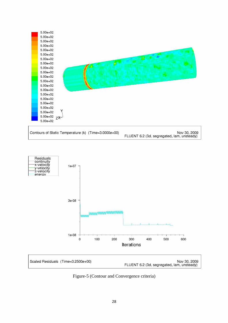
INTRODUCTION OF MOVING MEHH CONCEPT:
As our experiment involves the moving heat source, so it will be a case of unsteady
condition. The mesh which was given an initial condition was also moving from one end to
other end of workpiece. So at every instant the surface temperature will change with time and
position of moving mesh or say moving flame.
Figure-4 (Modelling with moving mesh concept)
28
Figure-5 (Contour and Convergence criteria)
29
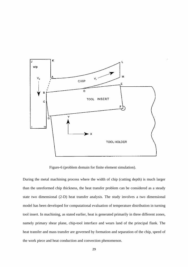
Figure-6 (problem domain for finite element simulation).
During the metal machining process where the width of chip (cutting depth) is much larger
than the unreformed chip thickness, the heat transfer problem can be considered as a steady
state two dimensional (2-D) heat transfer analysis. The study involves a two dimensional
model has been developed for computational evaluation of temperature distribution in turning
tool insert. In machining, as stated earlier, heat is generated primarily in three different zones,
namely primary shear plane, chip-tool interface and wears land of the principal flank. The
heat transfer and mass transfer are governed by formation and separation of the chip, speed of
the work piece and heat conduction and convection phenomenon.

30
The basic governing equations to be solved for this heat transfer problem are discussed
earlier.
The insert is considered as a whole one type of material and so the chip and workpiece.
Referred to figure-5, the three heat generation zones are:
AB: The shear zone
BD: The chip-tool interface.
BC: The work-tool interface
Length of the chip is taken equal to the square insert dimension for convenience sake equal to
12 mm. The far boundaries of the workpiece are assumed to be unaffected by the internal
heat generation sources.
A default meshing has been applied to whole domain.
Figure 7: (mesh generation default)

31
Evolution of Boundary Conditions: (according to fig-6)
At the outlet boundary of chip a zero temperature gradient condition was employed.
The two sides of the tool insert which are in contact with tool holder, a constant temperature
2500 C value was assumed.
So EF and FG are at 2500C.
JK and IH are the far dimensions of workpiece, which are assumed to unaffected by heat
generation sources. So,
JK is assumed to be at ambient condition say 400C.
IH is assumed to be thermally insulated.
The other two dimensions of workpiece IJ and CH are assumed to be at 5000C, which is the
flame temperature. The flame is in direct surface contact with the workpiece.
KA, AL, LM, MD, DE and GC are assumed to be thermally insulated boundaries i.e adiabatic
wall condition.
The Internal Heat Generation Rates:
Theoretically the heat generation rates along the three zones are given as the following with
an assumption that entire work done is getting converted to heat.
Let
Q: total heat generated
Q1 : heat generated in shear zone
Q2 : heat generated at rake face ( chip-tool interface)
Q3 : heat generated at flank wear land (work-tool interface).

32
Heat flux are calculated as:
Q = PzVc.
Q1 = Q-Q2.
Q2 = F1Vf.
Q3 = F2Vc.
Where,
Pz= tangential cutting force
F1= frictional force on rake face
F2= frictional force at wear land.
Vc= cutting velocity
Vf= bulk chip flow velocity.
Assuming the convective heat transfer coefficient value and applying boundary condition
along with assumptions of heat generation rates, iteration were carried out. A total no. of
1000 iterations were designed in fluent solver.
The physical properties of both the workpiece and tool material were added to database in
fluent to get appropriate results.
The chip-tool contact length was assumed to be a constant multiple of chip thickness for easy
approximations. It is generally taken as 4-5 times of chip thickness.
Length of the chip is taken equal to 12mm.
Frictional force on wear land was assumed to be equal to 30N.

33
Temperature distribution in tool insert, chip and workpiece:
Figure 8- (Temperature distribution).
5

34
Figure 9: (Residual of iterations and convergence criteria).

35
Figure 10: Insert rake face temperature.
0
100
200
300
400
500
600
700
800
0 2 4 6 8 10 12 14
Tem
era
ture
(c)
Distance along rake face of tool (mm)
Tool rake face temperature

36
Hard turning:
For some materials the machining methods may not be very cost efficient or effective. One
such material is high chromium white cast iron, which is used in the manufacture of mining
pumps and components.
A workpiece of high chromium white cast iron is to be hard turned by a coated carbide tool
insert.
Composition of workpiece (%):
C Si Mn S P Cr Ni Mo
2.7-2.9 0.4-0.8 0.5 0.1 0.1 15-20 0.6-0.8 1.2-2
Design of experiment:
No. of control factor-3
A-Depth of cut.
B- Feed.
C- Cutting velocity.
We assumed each factor to be set at 2 levels. High (1) and Low (0).
L4: Orthogonal array table:
Run A B C
1 1 1 2
2 1 2 1
3 2 1 1
4 2 2 2
37
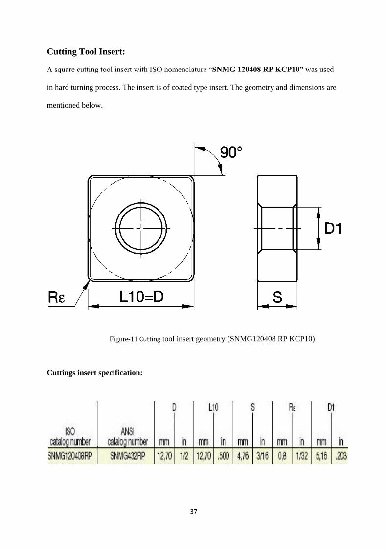
Cutting Tool Insert:
A square cutting tool insert with ISO nomenclature “SNMG 120408 RP KCP10” was used
in hard turning process. The insert is of coated type insert. The geometry and dimensions are
mentioned below.
Figure-11 Cutting tool insert geometry (SNMG120408 RP KCP10)
Cuttings insert specification:
38
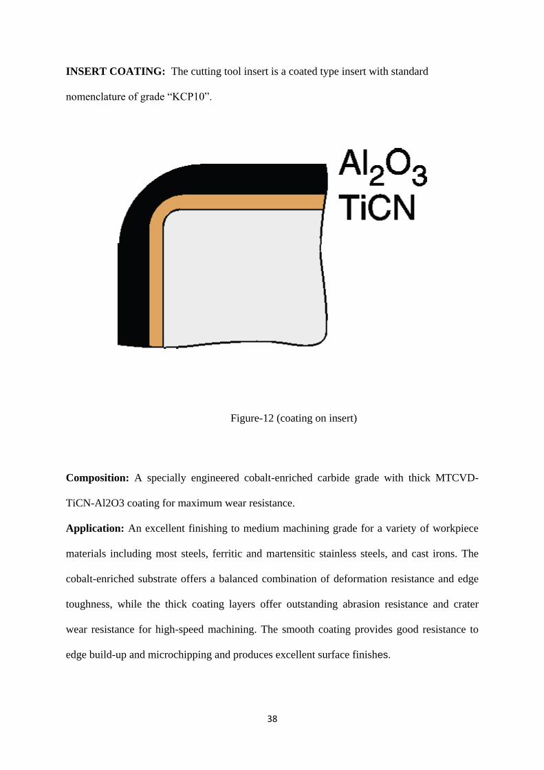
INSERT COATING: The cutting tool insert is a coated type insert with standard
nomenclature of grade “KCP10”.
Figure-12 (coating on insert)
Composition: A specially engineered cobalt-enriched carbide grade with thick MTCVD-
TiCN-Al2O3 coating for maximum wear resistance.
Application: An excellent finishing to medium machining grade for a variety of workpiece
materials including most steels, ferritic and martensitic stainless steels, and cast irons. The
cobalt-enriched substrate offers a balanced combination of deformation resistance and edge
toughness, while the thick coating layers offer outstanding abrasion resistance and crater
wear resistance for high-speed machining. The smooth coating provides good resistance to
edge build-up and microchipping and produces excellent surface finishes.
39
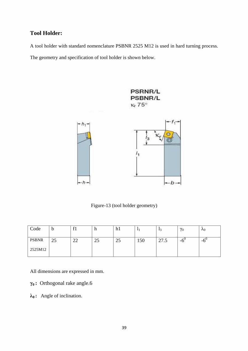
Tool Holder:
A tool holder with standard nomenclature PSBNR 2525 M12 is used in hard turning process.
The geometry and specification of tool holder is shown below.
Figure-13 (tool holder geometry)
Code b f1 h h1 l1 l3 γ0 λ0
PSBNR
2525M12
25 22 25 25 150 27.5 -60
-60
All dimensions are expressed in mm.
γ0 : Orthogonal rake angle.6
λ0 : Angle of inclination.

40
CHAPTER 4
RESULTS AND DISCUSSIONS
The CFD modelling of hot machining operation was carried out. The predicted results
achieved from CFD simulation were found to be deviated from measured ones. Some of the
assumptions might have led the model results to deviate from real values.
A graph has been plotted showing the temperature distribution over the rake face of tool
insert. The standard chip-tool interface temperature distribution has a bit higher value than
the predicted value. The reasons behind this deviation may be assumption of uniform and
equal heat flux value along all the three heat generation zone. As the new chip is just
generated and flows over the rake surface of the tool, so its temperature was found to be
lower. Again gradually the temperature at the interface rises due to the heat generated by
friction. After the mid of chip tool interface there is a gradual reduction in temperature
because the amount heat flux reduces. Thus the chip-tool interface temperature was recorded
maximum at the mid point of the insert.
The increase in temperature along the ware land of flank face of insert was not found much
appreciable during the modelling. This may be explained by the fact that the large dimension
work piece might have taken away the heat generated along the wear land.
The average temperature along the shear plane was recorded to be around 3500 C.

41
Future Work:
Improved set of boundary conditions:
The boundary conditions adopted for the model must be converted to more practical rather
assuming the adiabatic conditions in contact of atmosphere.
To carry out the experiment:
The experiment was not conducted during the course of project work due to unavailability of
sources. For having a complete idea for simulation modelling, the experiment must be
conducted in future.
Comparison of experimental and simulated results:
There must be held a comparison between experimental and simulated results to validate the
Modelling.
42
REFERENCES
[1] International journal of machine tool and manufacture
ISSN (1941-7020), ISSN (0924-0136), (Vol-45, issue-13, 2005), [Vol-41, Issue-51,
December 2001, pages (2271-2285],
[2] An introduction to “Computational Fluid Dynamics”-the finite volume method,
{H.K. Vesteeg, W.Malalasekera}
[3] Huddle, D., 2001, New Hard Turning Tools and Techniques Offer a cost-
effective Alternative to Grinding, Tooling and Production Magazine.
[4]- Nakayama, K., Arai, M., and Kanda, T., "Machining Characteristics of Hard
Materials", CIRP Annals. Vol. 37, Issue. 1, 1988, p.89-92
[5] Ozler, L., Inan, A., Ozel, C., 2000. Theoretical and experimental determination of
tool life in hot machining of austenitic manganese steel. Int. J. Mach. Tool & Manuf.
41,163–172.
[6] E.O. Ezugwa, 2005, Improvement in the machining of difficult aerospace super
alloy, Int. J. Mach. Tool& Manuf.45,1353-1367.
[7] Outinen J., Mechanical properties of structural steels at elevated temperatures and
after cooling down, Fire and Materials Conference, San Francisco, USA, Proceedings,
Interscience Communications Limited, UK, 2006.

43
[8] R.J.Karbacher, M.E.Merchant, 1951, Basic factors in Hot-machining of metals,
Transactions ASME73, 761-776
[9] J.R.Macy, 1952, US PATENT, Heating device for hot machining apparatus.
[10] Z.Y.Wang ,K.P. Pajurkar,J.Fan,S.lei, Y.C.Shin, G.Perfrescu, 2003,Hybrid
machining of Inconel 718, Int. J. of Mach. Tools& Manuf.43 ,1391-1396.
[11] N.Tosun,L.Ozler,2002,A study of tool life in hot-machining using artificial
neural networks and regression analysis method, J. Material processing technology
124,99-104.
[12] N. Tosun ,L. Ozler, 2004, Optimization for hot turning operations withmultiple
Performance characteristics, Int J Adv Manuf Technol 23, 777– 782.
[13] K.P. Maity, P.K. Swain, An experimental investigation of hot machining to
predict tool life, Int. J. of Materials processing technology 1 9 8 (2008) 344–349.
[14] König, W. and Zaboklicki, A. K., "Laser-assisted hot machining of ceramics and
composite materials", NIST Special Publication 847. Proceedings of the International
Conference on Machining of Advanced Materials. Vol. 847, 1993, p.455-463
[15]-Rozzi, J. C. , Pfefferkorn, F. E., Shin, Y. C., and Incropera, F. P., "Experimental
Evaluation of the Laser Assisted Machining of Silicon Nitride Ceramics.", Journal of
Manufacturing Science & Engineering, Transactions of the ASME, Vol. 122, Iss. 4,
2000, p.666-670

44
[16]- J. Mater. Process. Technol. 44 (1994) 199-206 Journal of Materials Processing
Technology, Hot Machining Process for improved Metal Removal R a t e s in turning
operations, G Madhavulu and Basheer Ahmed,
Technology Development Laboratory, Bharat Heavy Electricals Ltd., Corporate R&D
Division, Vikasnagar, Hyderabad - 500 593, India
[17]- Cutting Performance of Coated Carbides in Electric Hot Machining of Low
Machinability Metals, Kunio Ueharaa, Mitsuru Sakuraia and Hideo Takeshitaa
A Toyo University/Japan
[18] Chou, Y. K. , Evans, C. J., and Barash, M. M., "Experimental investigation on
CBN turning of hardened AISI 52100 steel", Journal of Materials Processing
Technology, Vol. 124, Iss. 3, 2002, p.274-283
[19] Lin, Z. C. and Chen, D. Y., "A study of cutting with a CBN tool", Journal of
Materials Processing Technology, Vol. 49, Iss. 1-2, 1995, p.149-164
[20] Wells, P., O'Loughlin, W., Hinckley, B., and Emms, S., Private conversation,
Weir Warman Ltd., 9 Mar. 2004
[21] Albert, M., "Taking the Fear out of Hard Turning", Modern Machine Shop, Vol.
68, Iss. 11, 1996, p.102-105
[22] Notter, A. T. and Heath, P. J., 'The Selection of Machining Parameters Using
Amborite', Ultrahard Materials in Industry machining with Amborite, De Beers
Industrial Diamond Division, London, 1985,

45
[23] Ng, E., Aspinwall, D. K., Brazil, D., and Monaghan, J., "Modelling of
temperature and forces when orthogonally machining hardened steel", International
Journal of Machine Tools and Manufacture, Vol. 39, Iss. 6, 1999,
Page 115 p.885-903
[24] Emms, Sarah, personal email, 29 July 2002
[25] Ng, E. and Aspinwall, D. K., "The Effect of Workpiece Hardness and Cutting
Speed on the Machinability of", Journal of Manufacturing Science and Engineering
[H.W. Wilson - AST], Vol. 124, Iss. 3, 2002, p.588
[26]- www.sciencedirect.com
[27] www.wikipedia.org
[28] Vaporization of LPG by ambient air, Panadda Phu-akat, Suvit Tia and Bunyaphat
Suphanit Chemical Engineering Department, King MongkutGs University of
Technology Thonburi, 91 Pracha-Uthit Rd., Bangmod Thungkru Thailand 10140, Tel.
0-2470-9234 ext. 409, Fax 0-2427-8077, E-mail: [email protected].
[29] Tay, A. O., Stevenson, M. G., and Davis, G. V., 1974, „„Using the Finite Element
Method to Determine Temperature Distribution in Orthogonal Machining,‟‟ Proc. Inst.
Mech. Eng., 188, pp. 627–638.
[30] Tay, A. O., Stevenson, M. G., Davis, G. V., and Oxley, P. L. B., 1976, „„A
Numerical Method for Calculating Temperature Distribution in Machining from Force
and Shear Angle Measurements,‟‟ Int. J. Mach. Tool Des. Res., 16, pp. 335–349.

46
[31]. Stevenson, M. G., Wright, P. K., and Chow, J. G., 1983, „„Further Developments
in Applying the Finite Element Method to the Calculation of Temperature
Distributions in Machining and Comparisons with Experiment,‟‟ASME J. Eng. Ind.,
105, pp. 149–154.
[32]. Muraka, P. D., Barrow, G., and Hinduja, S., 1979, „„Influence of the Process
Variables on the Temperature Distribution in Orthogonal Machining using the Finite
Element Method,‟‟ Int. J. Mach. Tool Des. Res., 21, pp. 445.


