
Ceramic Counter-Top Unit Instruction Manual

Congratulations, You have just purchased the Finest Water Revitalization System available.

CERAMIC CROCK
1. Take ceramic crock out of shipping box and clean before assembling.

2. Assemble dispenser faucet to the ceramic crock in order as shown in photograph
DISPENSER FAUCET
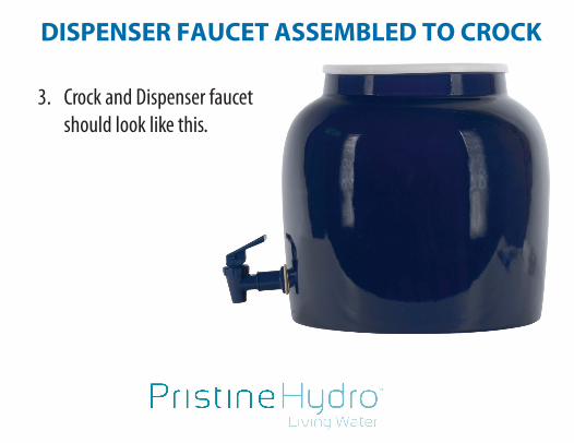
DISPENSER FAUCET ASSEMBLED TO CROCK
3. Crock and Dispenser faucet should look like this.

BASE ASSEMBLY
4. Wipe off base assembly unit and put on counter top.

BASE ASSEMBLY & CROCK TOGETHER
5. Place the crock and assembled dispenser faucet into the base assembly unit

6. Wipe the 0-ring of the float fill assembly to be sure that it is clean. Push in the release button on the rear deck of the unit body and insert the float fill assembly
FLOAT/FILL ASSEMBLY

7. Place cover on the crock.

9. Remove the aerator from your faucet

10. Replace the aerator with the faucet adaptor provided, it has both male and female threads. Tighten the faucet adapter to the faucet
taking care not to mar the polished surface. Pull the collar of the faucet connector assembly back, slip on to the faucet adaptor and turn on the cold water (never use hot water) After a few minutes the water will begin to enter the container

ADJUST THE DRAIN VALVE FLOW TO MATCH THE FLOW GOING INTO THE CROCK
11. The flow should be 1 to 11/2 gallons in 15 minutes, discard the first gallon. The crock will fill and the float will rise. When the float is in the full up position it will stop the flow going into the crock.
Drain Valve

TDS METER
Your PristineHydro Revitalization System includes a TDS (total dissolved solids) meter to monitor the water quality.!!Average readings should be 50 to 75 this reading represents the Magnesium in the water. !!Ranges vary because the chemistry varies with different water sources.

TDS METER When to change filters: First Filter Change check your water with the TDS Meter provided every year to year & 1/2 if the TDS meter reads over 100ppm its time for the first filter change with the following 2 filters: 5 Micron KDF after your first filter change you will gradually see the TDS start to drop back down to between 50 to 75 Second Filter Change: check your water with the TDS Meter provided every year to year & 1/2 if the TDS meter reads over 100ppm its time for the second filter change with the following 2 filters: DI Secondary DI after your second filter change you will gradually see the TDS start to drop down to between 50 to 75
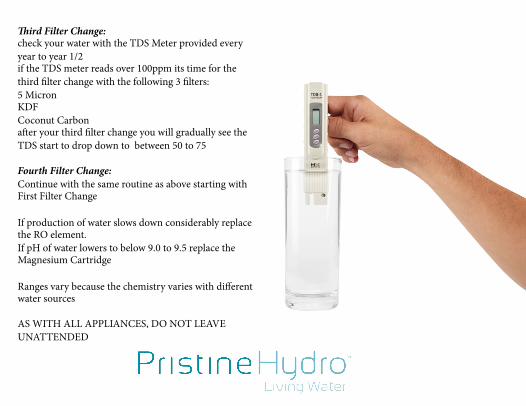
Third Filter Change: check your water with the TDS Meter provided every year to year 1/2 if the TDS meter reads over 100ppm its time for the third filter change with the following 3 filters: 5 Micron KDF Coconut Carbon after your third filter change you will gradually see the TDS start to drop down to between 50 to 75 Fourth Filter Change: Continue with the same routine as above starting with First Filter Change If production of water slows down considerably replace the RO element. If pH of water lowers to below 9.0 to 9.5 replace the Magnesium Cartridge Ranges vary because the chemistry varies with different water sources AS WITH ALL APPLIANCES, DO NOT LEAVE UNATTENDED

SHUT-OFF VALVE
NUMBERS SHOW FLOW PATTERN AND ARROWS SHOW FLOW DIRECTION. IDENTITY OF EACH
IS: 1. CTI CUSTOM KDF/SEH/HA 2. CT2 IN-LINE 5 MICRON 10' 3. CT3 CUSTOM 100 GPD
MEMBRANE 4. CT 4 CUSTOM CATION/ ANION 5. CT5 CUSTOM CATION/ ANION 6. CT6 CUSTOM MAGNESIUM ADDA
TIVE 7. CT7 IN-LINE CARBON 6'
REAR
Pristine H 'dr1

COUNTER TOP R.O. FILTER REPLACEMENT PROCEDURE
1. Turn off the faucet water supply to the unit. 2. Disconnect the unit from the faucet. 3. Empty the crock by opening the crock faucet 4. Remove the clear cover from the crock 5. Remove the crock fill spout by depressing the small lever where the spout is
connected to the white base of the unit. Pull the spout and the float valve that is attached to it straight up until the float clears the opening of the crock.
6. Remove the crock from the white system base. 7. Place the base assembly on a flat surface that is at least twice the size of the base.
There will be some water that will drain from the unit as you replace cartridges so working in an area where water damage will not be a problem or placing the unit on towels is important.

8. Remove the four (4) screws on the sides of the unit. 9. Lift the unit straight up – the weight of the filters will cause the inner base with
the filters to remain on the flat surface and the outer shell can then be set to the side adjacent to the inner base.
10. Refer to the drawing in your instructions titled CERAMIC COUNTER TOP FILTER IDENTITY
11. Remove the filter(s) that you wish to replace by pushing in the collar on the fittings on each end while simultaneously pulling on the tubes as shown on the following drawing.
COUNTER TOP R.O. FILTER REPLACEMENT PROCEDURE

12. Replace the filter(s) with the new filter(s) taking note of the flow direction marked on the replacement. Replacements are provided with new fittings. To replace the tubes, simply push the tube into the fitting until it hits an internal stop and will move no further. See the following drawing.
13. Re-assemble the system by reversing the above steps.
COUNTER TOP R.O. FILTER REPLACEMENT PROCEDURE


