
May 2006
4
FTIR Validation --- 2
Using Microscope Accessories --- 6
Question ---7Noise can be observed in the 4,000 to 3,400-cm-1 and 2,000 to 1,300-cm-1 ranges. How can this be eliminated?
New Products ---8
C103-E069

Spectroscopy Business Unit, Analytical & Measuring Instruments Division Kiyoshi Wada
FTIR Validation
In this article, we will look at ways FTIR validation is
performed. The word“validate” can be taken to mean
“enable”. The process of having your parking ticket
stamped at the cash register of your local department store
after buying some products is an example of“validation”.“Validate”has come to be used to refer to the process of
performing the required inspection for a system, checking
that it operates properly, and "enabling" it for use. In other
words, to“validate”a system is to recognize the propriety
of that system. Similarly,“validation” is used to mean
“ver i f i ca t ion”,“qua l i f i ca t ion”,“conf i rmat ion”,o r“legitimization”.Here, we will look at FTIR hardware and software
Hardware Validation
To perform“FTIR hardware validation” is to inspect an
FTIR system and confirm that it is operating properly.
With dispersive IR, inspection (correction) was performed
by measuring the spectra of polystyrene film and reading
the peak wavenumber to correct wavenumber accuracy.
With FTIR, the state of the system often manifests itself in
power spectra and so checking the shape and size of power
spectra is a relatively simple method that is used.
The method of checking the shape and size of power
spectra is used with Shimadzu FTIR systems as part of
daily inspection.
Several official bodies have issued standards related to the
methods used to perform more detailed inspections of FTIR
systems. Regulations are specified by industrial-standard
bodies such as the American Society for Testing and
Materials (ASTM) and the Japanese Industrial Standards
(JIS, the Japanese version of ASTM) Committee and by
publications such as the Japanese and European
Pharmacopoeias.
Let us look at the kind of standards established by each
body or publication.
JIS
Regulations are specified in JIS K0117 (General rules for
infrared spectrophotometric analysis). Inspection methods
are specified in 6.3 Calibration and Inspection Methods for Spectrophotometers. Points related to wavenumber
(precision), 0% transmittance, 100% transmittance, linearity,
resolution, and repeatability are specified. I will briefly
describe the methods specified by JIS. JIS does not,
however, give specific details on procedures or criteria.
Wavenumber (Accuracy)
This is obtained from the difference between the peak
wavenumber(s) positions for a substance with a well-known
peak wavenumber(s) position (e.g., atmospheric carbon
dioxide, water vapor, polystyrene, ammonia, or indene) and
the values indicated by the system.
0% Transmittance
A sample that does not allow the transmission of light is
measured in order to investigate the 0% transmittance,
namely, the error caused by stray light and secondary
emission spectra.
100% Transmittance
The 100% transmittance is investigated by performing
analysis without a sample and measuring the transmittance.
Linearity
A calibration curve for the absorbance and the
concentration is created and the linearity of this curve is
inspected.
Resolution
The resolution of absorbance peaks obtained using, for
example, ammonia or atmospheric carbon dioxide, is
investigated.
Reproducibility
A stable sample is measured at least twice within a short
period and it is confirmed that the variation in the
measurement values obtained for wavenumber and
transmittance is within the prescribed range.
FTIR TALK LETTER vol.402

ASTM
The ASTM standards are specified in E1421-99 Standard Practice for Describing and Measuring Performance of Fourier Transform Mid-Infrared (FT-MIR) Spectrometers; Level Zero and Level One Tests. With the ASTM standards,
unlike the JIS standards and the pharmacopoeias described
later, power spectra and spectrum of polystyrene films are
measured and it is confirmed that there are no FTIR
abnormalities or large changes over short and long periods.
I will briefly describe the methods specified in the ASTM
E1421-99 Level Zero tests.
Energy Spectrum Test Ð Changes in Power Spectra
Power spectra obtained in inspection are compared with
reference data and the spectra are checked for changes
over long periods.
One Hundred Percent Line Test Ð 100% Line Changes
Over Short Periods
100%T line spectra are calculated for power spectra
measured continuously in inspection and the spectra are
checked for changes over short periods.
Polystyrene Test Ð Comparison
of Polystyrene spectrum with Reference Data
Evaluation is performed using the differences between
spectra obtained for polystyrene film in inspection and
reference data.
The FTIR-8400S/IRPrestige-21 is equipped, as a standard
feature, with a validation program that conforms to the
ASTM E1421-99 Level Zero tests.
Japanese Pharmacopoeia
and European Pharmacopoeia
The relevant specifications are given under Instrument and adjustment in Infrared Spectrophotometry in General Tests, in supplement 1 to the fourteenth edition of the Japanese
Pharmacopoeia. Procedures and criteria are specified for
four inspection items: resolution (resolving power), wave
number precision, wave number reproducibility, and
transmittance reproducibility. The specifications of
supplement 1 to the fourteenth edition of the Japanese
Pharmacopoeia have been brought in line with those of the
European Pharmacopoeia (EP4.0).
The FTIR hardware validation methods used by Shimadzu
are based on the Japanese Pharmacopoeia methods,
which are aimed at the pharmaceutical industry and clearly
specify procedures and standards, and not on the
JIS/ASTM methods, which are aimed at industry and do not
clearly specify procedures.
Validation Program Conforming
to Japanese Pharmacopoeia
I will describe the validation program used with the FTIR-
8400S/IRPrestige-21. There are 5 inspection items: power
spectrum, resolution (resolving power), wave number
accuracy, wave number reproducibility, and transmittance
reproducibility. The performance of the system is inspected
by comparing measurement results with criteria values.
Power Spectrum
The most fundamental form of FTIR performance evaluation
can be conducted using the size of a power spectrum. The
sizes of a power spectrum at specified wavenumbers are
investigated; if they are no less than the criteria values at
each specified wavenumber then system performance
regarding this item is judged to be satisfactory.
Resolving Power (Resdution)
The following specification for resolving power is given in
supplement 1 to the fourteenth edition of the Japanese
Pharmacopoeia and in EP4.0.
The respective differences in transmittance are measured
and if they both are no less than the criteria values then
system performance regarding this item is judged to be
satisfactory.
Pharmacopoeia of the United States of America
FTIR is mentioned in the Pharmacopoeia of the United
States of America (USP). As shown below, however, it tells
the reader to refer to manufacturersÕ instruction manuals for
detailed instructions.
Detailed instructions for operating spectrophotometers are
supplied by manufacturers. To achieve significant and valid
results, the operator of a spectrophotometer should be
aware of its limitation and of potential sources of error and
variation. The instruction manual should be followed closely
on such matters as care, cleaning, and calibration of the
instrument, and ......
When the spectrum of a polystyrene film about 0.04 mm
thick is recorded, the depth of the trough from the
maximum absorption at about 2850 cm-1 to the minimum
at about 2870 cm-1 should be not less than 18%
transmittance and that from the maximum at about 1583
cm-1 to the minimum at about 1589 cm-1 should not be
less than 12% transmittance.
FTIR TALK LETTER vol.4 03
Wave number Accuracy
The following specification for wavenumber accuracy is
given in supplement 1 to the fourteenth edition of the
Japanese Pharmacopoeia and in EP4.0.
Transmittance Repeatability
The following specification for transmittance repeatability is
given in supplement 1 to the fourteenth edition of the
Japanese Pharmacopoeia.
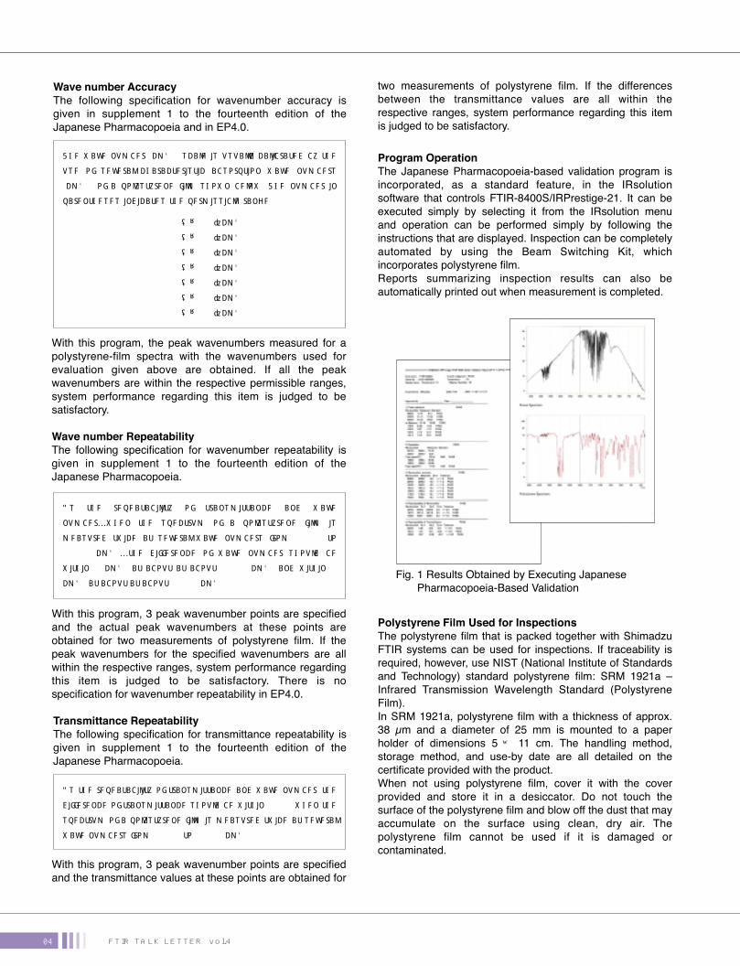
Fig. 1 Results Obtained by Executing Japanese
Pharmacopoeia-Based Validation
Wave number Repeatability
The following specification for wavenumber repeatability is
given in supplement 1 to the fourteenth edition of the
Japanese Pharmacopoeia.
With this program, the peak wavenumbers measured for a
polystyrene-film spectra with the wavenumbers used for
evaluation given above are obtained. If all the peak
wavenumbers are within the respective permissible ranges,
system performance regarding this item is judged to be
satisfactory.
Program Operation
The Japanese Pharmacopoeia-based validation program is
incorporated, as a standard feature, in the IRsolution
software that controls FTIR-8400S/IRPrestige-21. It can be
executed simply by selecting it from the IRsolution menu
and operation can be performed simply by following the
instructions that are displayed. Inspection can be completely
automated by using the Beam Switching Kit, which
incorporates polystyrene film.
Reports summarizing inspection results can also be
automatically printed out when measurement is completed.
Polystyrene Film Used for Inspections
The polystyrene film that is packed together with Shimadzu
FTIR systems can be used for inspections. If traceability is
required, however, use NIST (National Institute of Standards
and Technology) standard polystyrene film: SRM 1921a Ð
Infrared Transmission Wavelength Standard (Polystyrene
Film).
In SRM 1921a, polystyrene film with a thickness of approx.
38 µm and a diameter of 25 mm is mounted to a paper
holder of dimensions 5 × 11 cm. The handling method,
storage method, and use-by date are all detailed on the
certificate provided with the product.
When not using polystyrene film, cover it with the cover
provided and store it in a desiccator. Do not touch the
surface of the polystyrene film and blow off the dust that may
accumulate on the surface using clean, dry air. The
polystyrene film cannot be used if it is damaged or
contaminated.
With this program, 3 peak wavenumber points are specified
and the actual peak wavenumbers at these points are
obtained for two measurements of polystyrene film. If the
peak wavenumbers for the specified wavenumbers are all
within the respective ranges, system performance regarding
this item is judged to be satisfactory. There is no
specification for wavenumber repeatability in EP4.0.
With this program, 3 peak wavenumber points are specified
and the transmittance values at these points are obtained for
two measurements of polystyrene film. If the differences
between the transmittance values are all within the
respective ranges, system performance regarding this item
is judged to be satisfactory.
The wave number (cm-1) scale is usually calibrated by the
use of several characteristic absorption wave numbers
(cm-1) of a polystyrene film shown below. The number in
parentheses indicates the permissible range.
As the repeatability of transmittance and wave
numberÉwhen the spectrum of a polystyrene film is
measured twice at several wave numbers from 3000 to
1000 cm-1Éthe difference of wave number should be
within 5 cm-1 at about at about 3000 cm-1 and within 1
cm-1 at about at about 1000 cm-1.
As the repeatability of transmittance and wave number, the
difference of transmittance should be within 0.5% when the
spectrum of a polystyrene film is measured twice at several
wave numbers from 3000 to 1000 cm-1.
3060.0 (±1.5) cm-1�
2849.5 (±1.5) cm-1�
1942.9 (±1.5) cm-1�
1601.2 (±1.0) cm-1�
1583.0 (±1.0) cm-1�
1154.5 (±1.0) cm-1�
1028.3 (±1.0) cm-1
FTIR TALK LETTER vol.404

Fig. 2 Execution of Alteration-Check Program
Table 1 Changes Made to Japanese Pharmacopoeia
Software Validation
In addition to checking that the hardware is operating
properly, it is also necessary to check that the software is
operating properly. FTIR software has, however, become
very complex and it is impossible for the user to check all
the functions using black-box tests involving the input and
output of test data.
Software differs from hardware in that the influence of the
manufacturing process for each individual product on the
quality of that product is minimal and the product quality is
determined almost entirely by the development process.
Therefore, the user checks that software's configuration
files have not been corrupted or deleted using the
alteration-check program and also checks that the main
functions, such as the security functions and the basic data
analysis functions, operate properly. The software
development is validated by the appropriate implementation
of computer validation at the time of development.
Changes Made with Supplement 1
to the Fourteenth Edition
of the Japanese Pharmacopoeia
I imagine there are already people performing validation in
accordance with the old version of the Japanese
Pharmacopoeia. With supplement 1 to the fourteenth
edition of the Japanese Pharmacopoeia, which was
published on 27 December 2002, the specifications related
to resolving power and wave-number precision were
changed as shown in Table 1. Of particular note is the way
that the definition of the figures in parentheses has been
clarified, a point that caused a lot of misunderstanding.
Validation, Periodic Inspection,
and Operational Qualification
Basically, the same way of thinking applies to validation,
periodic inspection, and operational qualification. They all
involve the inspection and correction of FTIR systems at
regular intervals using specified techniques. At Shimadzu,
we recommend using the validation program to perform
periodic inspection and operational qualification.
Resolving�power�
(Resolution)
Wave number�accuracy 3027.1 (±0.3)�
2924 (±2)�
2850.7 (±0.3)�
1944 (±0.3)�
1871.0 (±0.3)�
1801.6 (±0.3)�
1601.4 (±0.3)�
1583.1 (±0.3)�
1181.4 (±0.3)�
1154.3 (±0.3)�
1069.1 (±0.3)�
1028.0 (±0.3)�
906.7 (±0.3)�
698.9 (±0.5)�
3060.0 (±1.5) cm-1�
2849.5 (±1.5) cm-1�
1942.9 (±1.5) cm-1�
1601.2 (±1.0) cm-1�
1583.0 (±1.0) cm-1
1154.5 (±1.0) cm-1�
1028.3 (±1.0) cm-1
Item Fourteenth edition of Japanese Pharmacopoeia Supplement 1 to Fourteenth Edition of Japanese Pharmacopoeia
When the spectrum of a polystyrene film about 0.04 mm thick is recorded, the depth of the trough from the maximum absorption at about 2851 cm-1 to the minimum at about 2870 cm-1 should be not less than 18% transmittance and that from the maximum at about 1583 cm-1 to the minimum at about 1589 cm-1 should not be less than 10% transmittance.
When the spectrum of a polystyrene film about 0.04 mm thick is recorded, the depth of the trough from the maximum absorption at about 2850 cm-1 to the minimum at about 2870 cm-1 should be not less than 18% transmittance and that from the maximum at about 1583 cm-1 to the minimum at about 1589 cm-1 should not be less than 12% transmittance.
The wave number (cm-1) scale is usually calibrated by the use of several absorption bands of a polystyrene film, shown below. The numbers in parentheses indicate the precision with which these values have been established.
The wave number (cm-1) scale is usually calibrated by the use of several characteristic absorption wave numbers (cm-1) of a polystyrene film shown below. The number in parentheses indicates the permissible range.
References
JIS
ASTM
Japanese Pharmacopoeia
European Pharmacopoeia
Pharmacopoeia of the United States of America
NIST
http://www.jisc.go.jp/eng/
www.astm.org
www.mhlw.go.jp/topics/bukyoku/iyaku/yakkyoku/
http://www.pheur.org/
http://www.usp.org/
http://www.nist.gov/
FTIR TALK LETTER vol.4 05

In volume 3 of the FTIR Talk Letter, we provided descriptions of the accessories that are required, or are useful, for effective
sampling in infrared microscopic measurement. Here, we will explain how to use infrared-microscope accessories to obtain
high-quality spectra.
Transmission Measurement with Infrared Microscope
When performing transmission measurement with an
infrared microscope, the sample is flattened and measured
using a transmission window plate. Transmission windows
are made from various materials; the well-known types
include those made from KBr, BaF2, diamond, and silicon
wafer. The characteristics of these windows vary and are
selected according to the actual measurement conditions.
1. KBrFeatures: This is a commonly used type. It is relatively
cheap and has an extremely high transmittance of 90% for
infrared light. (See Fig. 1.) The wide wave-number region of
4,000 to 400 cm-1 makes it possible to obtain high-quality
spectra.
Points to note: It is relatively soft and prone to damage. KBr
dissolves when used for samples containing moisture and is
therefore unsuitable for measurement in this case. Store it
at a humidity level not exceeding 50%. If a KBr window
plate is stored in a location with a high humidity level,
because of deliquescence, the window will become clouded
and it will not be possible to obtain high-quality spectra.
2. BaF2
Features: This is a commonly used type. It is relatively
cheap and has an extremely high transmittance of 90% for
infrared light. It has greater water-resistance than the KBr
type.
Points to note: It is relatively soft and prone to damage.
There is BaF2 absorption at wave numbers of less than 800
cm-1 and measurement is possible only down to approx. 720
cm-1. (See Fig. 1.) BaF2 dissolves when it is used for
samples containing acid or ammonia.
3. DiamondFeatures: This is a commonly used type. It is easy to
handle. It is a very hard substance and is extremely
resistant to damage. It is also relatively stable in terms of
chemical behavior and can be used for various types of
sample. It has a high transmittance of approx. 70% for
infrared light.
Points to note: It is more expensive than KBr and BaF2 The
area for which measurement is possible is small and, when
using relatively large samples, it is sometimes necessary to
cut and set the sample for measurement. The edges of the
window are not suitable for measurement.
There is diamond absorption in a neighborhood of 2,000 cm-1
and the S/N ratio is lower in this range. (See Fig. 1.) Also,
the refractive index of 2.4 is relatively high and the
difference between that of general samples makes the
appearance of interference fringes likely.
4. Silicon Wafer (High-Resistance Silicon Wafer)Features: This type is not commonly used. It is relatively
hard and easy to handle. Water can be used to clean it.
Points to note: It has a relatively low transmittance of
approx. 55% for infrared light, making it difficult to obtain
high-quality spectra. It also has the disadvantage of not
allowing transmission observation with visible light. Also, the
refractive index of 3.4 is high and the large difference
between that of samples makes the appearance of
interference fringes likely.
It can be seen from the above that, as for the type of
window plate used for transmission measurement
performed with plate an infrared microscope, diamond is
suitable for general-purpose and hard samples, and KBr
and BaF2 are suitable for high-sensitivity analysis.
Using Microscope Accessories
Fig. 1 Transmittance for Different Types of Window Material
Diamond
Tokyo Customer Support Center, Analytical Applications Department, Analytical & Measuring Instruments Division
Hirokazu Abo
FTIR TALK LETTER vol.406

�H2O H2OCO2 CO2
Without atmospheric �correction
With atmospheric correction
Using Diamond Cells (Points to Note When Flattening Samples)
A diamond cell consists of two discs into which diamonds
with dimensions of 2 to 3 mm are embedded. This
accessory is useful for making hard or irregularly shaped
samples thinner. Depending on the way it is used, however,
it may not be possible to obtain high-quality spectra. Here I
will describe how to use the diamond cell effectively.
Put an appropriate amount of the sample on a disk. Note
that if an amount of the sample that could be spread out
over the entire diamond cell is used, it will not be possible to
perform background measurement.
Put the other disk on top of the sample to flatten it out. With
soft samples, simply pressing with your hand is sufficient;
there is no need to use screws. With small, hard samples,
flattening the sample by turning the screw with a large force
may, in exceptional cases, cause cracks to appear at the
edge of the diamond. (See Fig. 2.)
It may not be possible to obtain high-quality spectra if
measurement is performed with the upper disk in place. For
example, the infrared light passes through windows twice,
which may adversely affect the transmittance; the large
diamond absorbance may also adversely affect the
transmittance; the direction of the light may become parallel
between the disks, making the appearance of interference
fringes extremely likely. Therefore, remove the upper disk
before measurement. Note that the sample may adhere to
the upper disk.
Put the disk to which the sample has adhered in the holder
and perform transmission measurement using an infrared
microscope. (See Fig. 3.)
Clean the windows after use. A simple method is to scrape
of any dust that has adhered to the windows using a swab
that has been soaked in water or alcohol.
Fig. 2 Flattening the Sample Fig. 3 Analyzing the Sample
The phenomenon that can be
observed in the 4,000 to
3,400cm-1 and 2,000 to 1,300cm-1
ranges is water vapor (H2O)
absorption. Absorption can be observed as noise because of
a change in the amount of water vapor resulting from a
change in the ambient conditions. In addition to water vapor,
carbon dioxide (CO2) absorption can be observed in
neighborhoods of 2,350cm-1 and 670cm-1.
The influence of water vapor and carbon dioxide can be
minimized by performing sample measurement immediately
after background measurement. It is also possible to reduce
the influence of these gases by purging the system with dry
air or nitrogen. This method, however, requires the use of
special equipment, such as a dry-air supply unit or a
nitrogen canister.
IRsolution software is equipped with an atmospheric-
correction function. Using this function makes it possible to
reduce the influence of water vapor and carbon dioxide.
(See below.)
Question
Answer
Noise can be observed in the 4,000 to 3,400-cm-1 and 2,000 to 1,300-cm-1 ranges. How can this be eliminated?
FTIR TALK LETTER vol.4 07

UV-VIS-NIR Spectrophotometer�SolidSpec-3700/3700DUV
UV-VIS-NIR Spectrophotometer�UV-3600
World First― High Sensitivity Achievedwith Installation of 3 DetectorsIn addition to a photomultiplier tube and a cooling-type PbS
detector, this UV-VIS-NIR spectrophotometer also incorporates an
InGaAs detector, giving it a much higher level of sensitivity in the
near-infrared region.
Large Sample Compartment Designedto Facilitate Nondestructive MeasurementThe compartment allows the measurement of horizontally placed
samples with dimensions of up to 700×560 mm. Using the
automatic X-Y stage (option) enables automatic multipoint
measurement of samples with dimensions of up to 310×310 mm.
Measurement of Deep Ultraviolet Region below 190 nmPurging the optical path with nitrogen gas makes it possible for the
SolidSpec-3700DUV to perform measurement in the 175 to 2,600-
nm range with an integrating sphere and in the 165 to 3,300-nm
range with an optional accessory.
High Sensitivity― Equipped with 3 DetectorsIn addition to a photomultiplier tube and a cooling-type PbS
detector, this UV-VIS-NIR spectrophotometer also incorporates an
InGaAs detector, giving it a much higher level of sensitivity in the
near-infrared region.
High Resolution, Ultra-Low Stray Light,and Wide Measurement RangeThis instrument achieves high resolution and ultra-low stray light
using a high-performance double monochromator. It is capable of
high-sensitivity measurement across the ultra-violet, visible, and
near-infrared regions, with a measurement wavelength range of
185 to 3,300 nm.
A Variety of Accessories for a Wide Rangeof ApplicationsA variety of accessories, such as the integrating-sphere
attachment, the electronic constant-temperature cell holder, or the
ultra-micro cell holder can be mounted to the instrument, allowing
it to handle a wide range of measurement applications.
UV-VIS-NIR SpectrophotometerSolidSpec-3700/3700DUV
UV-VIS-NIR SpectrophotometerUV-3600
3295-12508-30A-NS


