
BT Business Single Cell DECT Guide
C
ha
pte
r:
1
BT Business Single Cell DECT
Installation & Configuration Guide
BT BT Business Single Cell DECT Guide
BT Business Single Cell DECT Guide
C
ha
pte
r:
2
Contents
Contents ........................................................................................................................................................... 2
1 About This Document ............................................................................................................................... 4
1.1 Audience................................................................................................................................................. 4
1.2 When Should I Read This Guide .............................................................................................................. 4
1.3 Important Assumptions .......................................................................................................................... 4
1.4 What’s Inside This Guide ........................................................................................................................ 4
1.5 What’s Not in This guide......................................................................................................................... 5
1.6 Abbreviations ......................................................................................................................................... 5
1.7 References/Related Documentation ...................................................................................................... 5
2 Introduction – System Overview .............................................................................................................. 6
2.1 Hardware Setup ...................................................................................................................................... 6
2.2 Components of BT Business DECT System .............................................................................................. 6
2.2.1 Fijowave Base Station ................................................................................................................... 6
2.2.2 BT Business DECT Administration Server/Software ...................................................................... 6
2.2.3 Fijowave Wireless Handset ........................................................................................................... 7
2.3 Wireless Bands ....................................................................................................................................... 7
2.4 System Capacity (in Summary) ............................................................................................................... 7
3 Installation of Base Stations/Repeater ..................................................................................................... 8
3.1 Package – Contents/Damage Inspection ................................................................................................ 8
3.2 Fijowave Base station Mechanics ........................................................................................................... 9
3.3 Fijowave Base Unit – Reset feature ........................................................................................................ 9
3.4 Installing the Base Station ...................................................................................................................... 9
3.4.1 Mounting the Base Stations/Repeaters: ....................................................................................... 9
3.5 Find IP of Base Station .......................................................................................................................... 10
3.5.1 Using handset Find IP feature ..................................................................................................... 10
3.5.2 Using browser IPDECT ................................................................................................................ 10
3.6 Login to Base Configuration Interface .................................................................................................. 10
4 Preparing the Handset ............................................................................................................................ 12
5 BT Business DECT Administration Interface............................................................................................ 14
5.1 Web navigation .................................................................................................................................... 14
5.2 Home/Status ........................................................................................................................................ 16
5.3 Extensions ............................................................................................................................................ 17
5.3.1 Group call ................................................................................................................................... 17

BT Business Single Cell DECT Guide
C
ha
pte
r:
3
5.3.2 Add extension ............................................................................................................................. 18
5.3.3 Extensions list ............................................................................................................................. 20
5.3.4 Edit Extension ............................................................................................................................. 21
5.3.5 Handset list ................................................................................................................................. 21
5.4 Servers .................................................................................................................................................. 23
5.5 Network ................................................................................................................................................ 27
5.5.1 IP Settings ................................................................................................................................... 27
5.5.2 VLAN Settings ............................................................................................................................. 28
5.5.3 DHCP Options ............................................................................................................................. 28
5.5.4 NAT Settings ............................................................................................................................... 29
5.5.5 SIP/RTP Settings .......................................................................................................................... 29
5.6 Management Settings Definitions ........................................................................................................ 31
5.7 Time Server .......................................................................................................................................... 34
5.8 Country ................................................................................................................................................. 36
5.9 Security ................................................................................................................................................. 37
5.9.1 Certificates.................................................................................................................................. 37
5.9.2 SIP Client Certificates .................................................................................................................. 38
5.9.3 Password .................................................................................................................................... 38
5.10 Repeaters ........................................................................................................................................... 39
5.10.1 Add repeater .............................................................................................................................. 39
5.10.2 Register Repeater ....................................................................................................................... 41
5.10.3 Repeaters list .............................................................................................................................. 41
6 Functionality Overview ........................................................................................................................... 43
6.1 System Feature List .............................................................................................................................. 43
6.2 Detail Feature List ................................................................................................................................. 44

BT Business Single Cell DECT Guide
Ab
ou
t T
his
Do
cum
en
t C
ha
pte
r:
4
1 About This Document This document describes the configuration, customization, management, operation, maintenance and
trouble shooting of the BT Business DECT Single-Cell System (IP base, handset, and Repeater). For handset
detailed user guide refer to [1].
1.1 Audience
Who should read this guide? First, this guide is intended for networking professionals responsible for
designing and implementing Fijowave based enterprise networks.
Second, network administrators and IT support personnel that need to install, configure, maintain and
monitor elements in a “live” BT Business DECT network will find this document helpful.
1.2 When Should I Read This Guide
Read this guide before you install the core network devices of BT Business DECT System and when you are
ready to setup or configure SIP server, NAT aware router, advanced VLAN settings, base stations, and multi
cell setup.
This manual will enable you to set up components in your network to communicate with each other and
also deploy a fully functional BT Business DECT System.
1.3 Important Assumptions
This document was written with the following assumptions in mind:
1) You have understanding of network deployment in general
2) You have working knowledge of basic TCP/IP/SIP protocols, Network Address Translation, etc...
3) A proper site survey has been performed, and the administrator has access to these plans.
1.4 What’s Inside This Guide
We summarize the contents of this document in the table below:
Where Is It? Content Purpose
Chapter 2 Introduction to the VoIP
Network
To gain knowledge about the different elements in a
typical VoIP Network
Chapter 3 Installation of Base
station/Repeater
Considerations to remember before unwrapping and
installing base units and repeaters
Chapter 4 Making Handsets Ready To determine precautions to take in preparing
handsets for use in the system
Chapter 5 VoIP Administration
Interface
To learn about the Configuration Interface and define
full meaning of various parameters needed to be setup
in the system.
Chapter 6 System Functionality
Overview
To gain detail knowledge about the system features.

BT Business Single Cell DECT Guide
Ab
ou
t T
his
Do
cum
en
t C
ha
pte
r:
5
1.5 What’s Not in This guide
This guide provides overview material on network deployment, how-to procedures, and configuration
examples that will enable you to begin configuring your BT Business DECT System.
It is not intended as a comprehensive reference to all detail and specific steps on how to configure other
vendor specific components/devices needed to make the BT Business DECT System functional. For such a
reference to vendor specific devices, please contact the respective vendor documentation.
1.6 Abbreviations
For the purpose of this document, the following abbreviations apply:
DHCP: Dynamic Host Configuration Protocol
DNS: Domain Name Server
HTTP(S): Hyper Text Transfer Protocol (Secure)
(T)FTP: (Trivial) File Transfer Protocol
IOS: Internetworking Operating System
PCMA: A-law Pulse Code Modulation
PCMU: mu-law Pulse Code Modulation
RTP: Real-time Transport Protocol
RPORT: Response Port (Refer to RFC3581 for details)
SIP: Session Initiation Protocol
: Small and Medium scale Enterprise
VLAN: Virtual Local Access Network
TOS: Type of Service (policy based routing)
URL: Uniform Resource Locator
UA: User Agent
1.7 References/Related Documentation [1]: BT Business DECT Handset Guide

BT Business Single Cell DECT Guide
Intr
od
uct
ion
– S
yst
em
Ov
erv
iew
C
ha
pte
r:
6
2 Introduction – System Overview
In a typical telephony system, the network setup is the interconnection between Base-stations, routers,
repeaters, portable parts, etc. The back-bone of the network depends on the deployment scenario but a
ring or hub topology is used. The network has centralized monitoring, and maintenance system.
The BT Business DECT single cell base station supports up to 20 registered handsets. The base supports the
IP DECT CAT-IQ repeater with support for up to 5 channels simultaneous call sessions.
2.1 Hardware Setup
BT Business DECT network hardware setup can deployed as follows:
Base-station(s) are connected via Layer 3 and/or VLAN Aware Router depending on the deployment
requirements. The Layer 3 router implements the switching function.
The base-station can be desk mounted or wall mounted. Radio coverage can be extended using repeaters.
Repeaters are range extenders and cannot be used to increase local capacity issues.
The base-station antenna mechanism is based on space diversity feature which improves coverage. The
base-stations uses complete DECT MAC protocol layer and IP media stream audio encoding feature to
provide up to 6 simultaneous calls.
2.2 Components of BT Business DECT System
The BT Business DECT system is made up of (but not limited to) the following components:
• One Fijowave Base Station is connected over an IP network and using DECT as air-core interface.
• Fijowave IP DECT wireless Handset.
• BT Business DECT Configuration Interface; is a management interface for BT Business DECT Wireless
Solution.
2.2.1 Fijowave Base Station
The Base Station converts IP protocol to DECT protocol and transmits the traffic to and from the end-nodes
(i.e. wireless handsets) over a channel. It has 6 available channels.
2.2.2 BT Business DECT Administration Server/Software
This server is referred to as VoIP Configuration Interface.
The VoIP Configuration Interface is a web based administration page used for configuration and
programming of the base station and relevant network end-nodes. E.g. handsets can be registered or de-
registered from the system using this interface.
The configuration interface can be used as a setup tool for software or firmware download to base stations,
repeaters and handsets. Further, it is used to check relevant system logs that can be useful to
administrator. These logs can be used to troubleshoot the system when the system faces unforeseen
operational issues.
BT Business Single Cell DECT Guide
Intr
od
uct
ion
– S
yst
em
Ov
erv
iew
C
ha
pte
r:
7
2.2.3 Fijowave Wireless Handset
The handset is a lightweight, ergonomical and portable unit compatible with Wideband Audio (G.722),
DECT, GAP standard, CAT-iq audio compliant.
The handset includes Colour display with graphical user interface. It can also provide the subscriber with
most of the features available for a wired phone, in addition to its roaming and handover capabilities. Refer
to the relevant handset manuals for full details handset features.
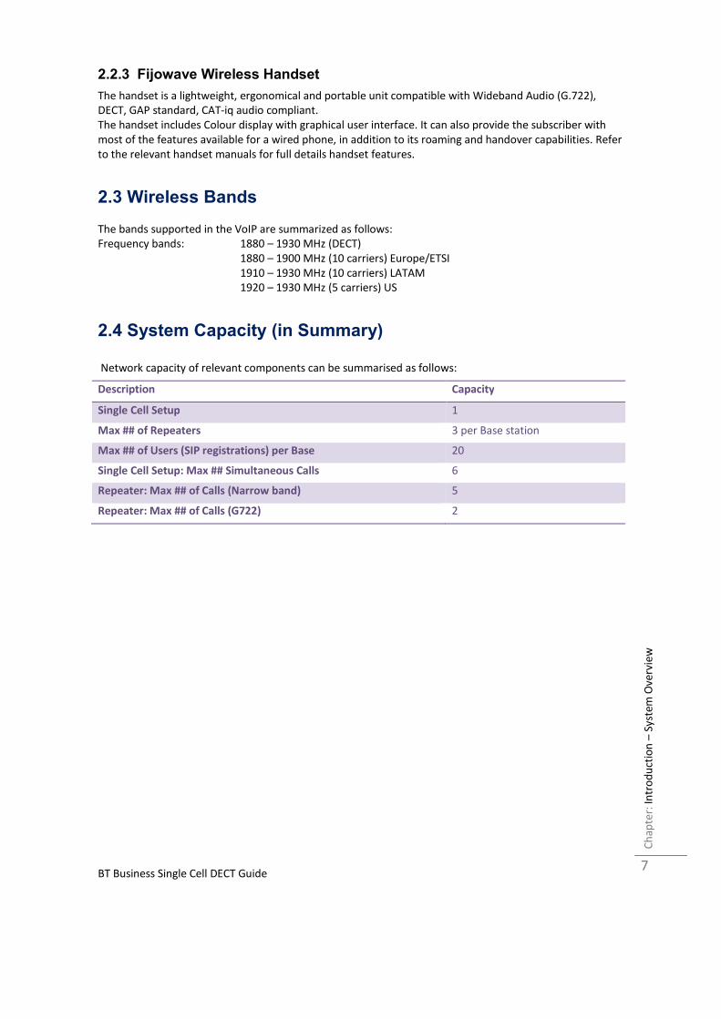
2.3 Wireless Bands
The bands supported in the VoIP are summarized as follows:
Frequency bands: 1880 – 1930 MHz (DECT)
1880 – 1900 MHz (10 carriers) Europe/ETSI
1910 – 1930 MHz (10 carriers) LATAM
1920 – 1930 MHz (5 carriers) US
2.4 System Capacity (in Summary)
Network capacity of relevant components can be summarised as follows:
Description Capacity
Single Cell Setup 1
Max ## of Repeaters 3 per Base station
Max ## of Users (SIP registrations) per Base 20
Single Cell Setup: Max ## Simultaneous Calls 6
Repeater: Max ## of Calls (Narrow band) 5
Repeater: Max ## of Calls (G722) 2

BT Business Single Cell DECT Guide
Inst
alla
tio
n o
f B
ase
Sta
tio
ns/
Re
pe
ate
r C
ha
pte
r:
8
3 Installation of Base Stations/Repeater
In the following we briefly describe the how to install the base station in this chapter.
3.1 Package – Contents/Damage Inspection
Contents of Package: Make sure all relevant components are available in the package before proceeding to the next step.
Every shipped base unit package/box contains the following items:
• 1 x Cat. 5 cable (Ethernet cable)
• Base unit
• AC adaptor (Ten Pau S003GB0500060)

BT Business Single Cell DECT Guide
Inst
alla
tio
n o
f B
ase
Sta
tio
ns/
Re
pe
ate
r C
ha
pte
r:
9
3.2 BT Base station Mechanics
The base station front end shows a LED indicator that signals different functional states of the base unit and
occasionally of the overall network. The indicator is off when the base unit is not powered.
The table below summarises the various LED states:
LED State State
Unlit No power in unit
Unlit/Solid red Error condition
Blinking green Initialisation
Solid red Factory reset warning or long press in BS reset button
Blinking red Factory setting in progress
Solid green Ethernet connection available (Normal operation)
Blinking red Ethernet connect not available OR handset de/registration failed
Solid red Critical error (can only be identified by BT Engineers). Symptoms
include no system/SIP debug logs are logged, etc.
Orange Press reset button of base station.
3.3 BT Base Unit – Reset feature
It is possible to restart or reset the base station unit by pressing a knob at the rear side of the unit.
Alternatively, it can be reset from the Configuration Interface.
3.4 Installing the Base Station
First determine the best location that will provide an optimal coverage taking account the construction of
the building, architecture and choice of building materials.
Next, mount the Base Station on a wall to cover range between 50 – 300 meters (i.e. 164 to 984 feet),
depending whether it’s an indoor or outdoor installation.
3.4.1 Mounting the Base Stations/Repeaters:
We recommend the base station be mounted an angle other than vertical on both concrete/wood/plaster
pillars and walls for optimal radio coverage. Avoid mounting the base units upside down as it significantly
reduces radio coverage.
Mount the base unit as high as possible to clear all nearby objects (e.g. office cubicles and cabinets, etc.).
Occasionally extend coverage to remote offices/halls with lower telephony users by installing Repeaters.
Make sure that when you fix the base stations with screws, the screws do not touch the PCB on the unit.
Secondly, avoid all contacts with any high voltage lines.

BT Business Single Cell DECT Guide
Inst
alla
tio
n o
f B
ase
Sta
tio
ns/
Re
pe
ate
r C
ha
pte
r:
10
3.5 Find IP of Base Station To find IP of the installed base station two methods can be used; Using handset Find IP feature or browser
IPDECT feature.
3.5.1 Using handset Find IP feature
On the handset press “Menu” key followed by the keys: *47* to get the handset into find bases
menu. The handset will now scan for bases.
- Use the cursor down/up to select the base MAC address for the base
- The base IP address will be shown in the display
The feature is also used for deployment. For further details refer to reference [2].
3.5.2 Using browser IPDECT
Open any standard browser and enter the address:
http://ipdect<MAC-Address-Base-Station>
for e.g. http://ipdect38b74d000afb. This will retrieve the HTTP Web Server page from the base station with
hardware address 38b74d000afb.
This feature requires an available DNS server.
3.6 Login to Base Configuration Interface
STEP 1 Connect the Base station to a private network via standard Ethernet cable (CAT-5).
STEP 2 Use the IP find menu in the handset (Menu *47*) to determine the IP-address of the base
station by matching the MAC address on the back of the base station with the MAC address list in
the handset.
STEP 3 On the Login page, enter your authenticating credentials (i.e. username and password). By
default the username and password is admin. Click OK button.
STEP 4 Once you have authenticated, the browser will display front end of the Configuration
Interface. The front end will show relevant information of the base station.

BT Business Single Cell DECT Guide
Inst
alla
tio
n o
f B
ase
Sta
tio
ns/
Re
pe
ate
r C
ha
pte
r:
11

BT Business Single Cell DECT Guide
Pre
pa
rin
g t
he
Ha
nd
set
Ch
ap
ter:
12
4 Preparing the Handset
We briefly describe how to prepare the handset for use, install, insert and charge new batteries.
Package – Contents
Contents of Package:
Make sure all relevant components are available in the package before proceeding to the next step.
Every shipped handset unit package/box contains the following items:
• 1 x Handset hook
• 1 x A/C Adaptor (Ten Pau S008CM0550060)
• 1 x Rechargeable Battery (Lithium-Ion battery 3.7V, 1100mAh)
• 1 x Charger
• 1 x Handset Unit, 1 x Battery cover
Before Using the Phone
Here are the pre-cautions users should read before using the Handset:
Installing the Battery
1. Never dispose battery in fires, otherwise it will explode.
2. Never replace the batteries in potentially explosive environments, e.g. close to inflammable liquids/
gases.
3. ONLY use approved batteries and chargers from the vendor or operator.
4. Do not disassemble, customise or short circuit the battery
Using the Charger

BT Business Single Cell DECT Guide
Pre
pa
rin
g t
he
Ha
nd
set
Ch
ap
ter:
13
Each handset is charged through the use of a handset charger. The charger is a compact desktop unit
designed to charge and automatically maintain the correct battery charge levels and voltage.
The charger Handset is powered by AC supply from 110-240VAC that supplies 5.5VDC at 600mA.
When charging the battery for the first time, it is necessary to leave the handset in the charger for at least
10 hours before the battery is fully charged and the handset ready for use.
Handset in the Charger
For correct charging, ensure that the room temperature is between 0°C and 25°C/32°F and 77°F. Do not
place the handset in direct sunlight. The battery has a built-in heat sensor which will stop charging if the
battery temperature is too high.
If the handset is turned off when placed in charger, only the LED indicates the charging. When handset is
turned off, the LED flashes at a low frequency while charging and lights constantly when the charging is
finished. There will be response for incoming calls.
If the handset is turned on when charging, the display shows the charging status.
Open Back Cover
1. Press down the back cover and slide it towards the bottom of the handset.
2. Remove Back Cover from Handset
Handset Serial Number
The serial number of each handset is found either on a label, which is placed behind the battery, or on the
packaging label. First, lift off handset back cover and lift the battery and read the serial number.
Replace Battery
Remove Back Cover from Handset. Remove the old battery and replace with a new one.
BT Business Single Cell DECT Guide
BT
Bu
sin
ess
DE
CT
Ad
min
istr
ati
on
In
terf
ace
C
ha
pte
r:
14
5 BT Business DECT Administration Interface
The VoIP Administration Interface is the main interface through which the system is managed and
debugged.
The VoIP Configuration Interface is an in-built HTTP (s) Web Server service residing in each base station.
This interface is user friendly interface and easy to handle even to a first time user.
Note: Enabling secure web will decrease web server speed perceived by the user. The MS internet explorer
caches more data and as such this browser is recommended in secure web mode.
This chapter seeks to define various variables/parameters available for configuration in the network.
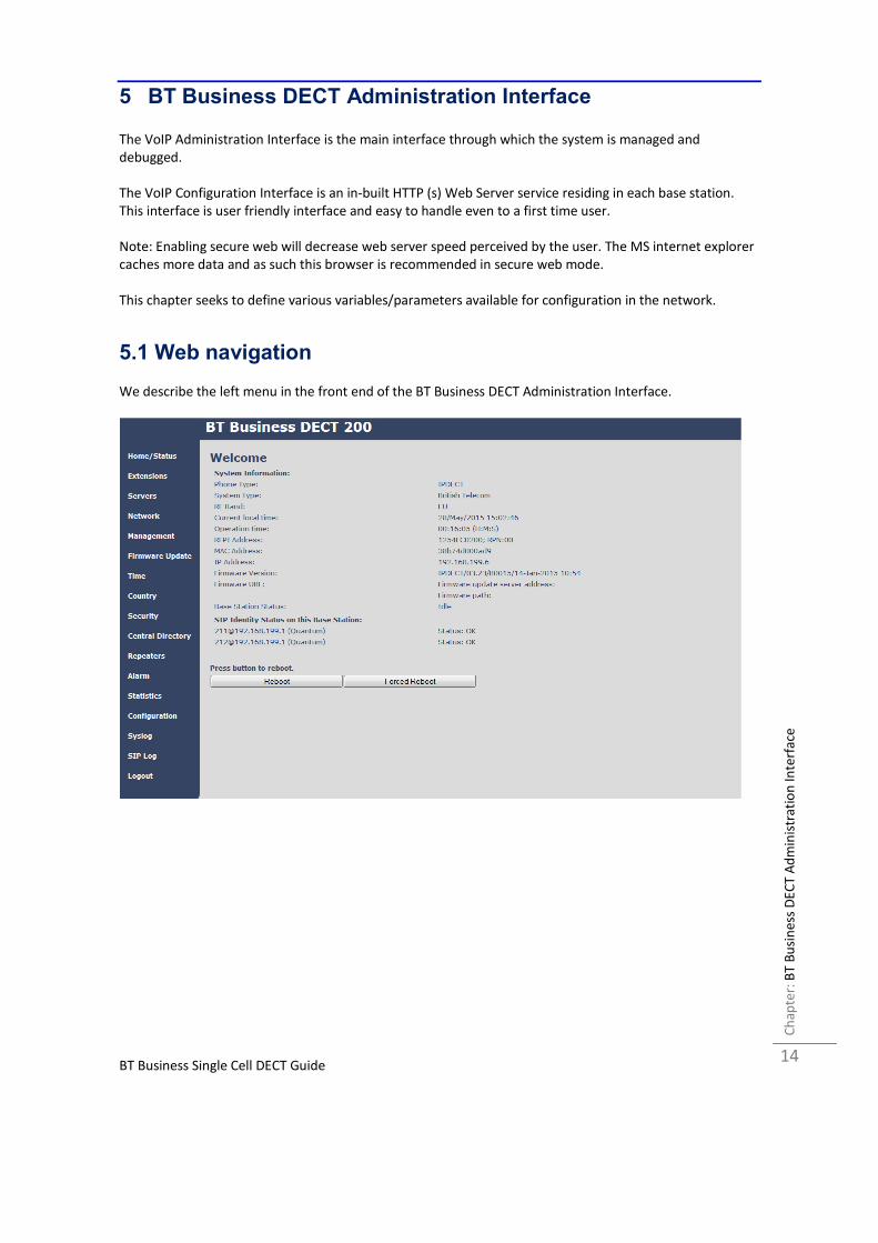
5.1 Web navigation
We describe the left menu in the front end of the BT Business DECT Administration Interface.

BT Business Single Cell DECT Guide
BT
Bu
sin
ess
DE
CT
Ad
min
istr
ati
on
In
terf
ace
C
ha
pte
r:
15
Feature Description
Home/Status This is the front end of the Base station’s HTTP web interface. This page shows the
summary of current operating condition and settings of the Base station and
Handset(s).
Extensions Administration of extensions and handsets in the system
Servers On this page the user can define which SIP/NAT server the network should connect
to.
Network Typically the user configures the Network settings from here.
NAT provisioning: allows configuration of features for resolving of the NAT –
Network Address Translation. These features enable interoperability with most
types of routers.
DHCP: allows changes in protocol for getting a dynamic IP address.
Virtual LAN: specifies the Virtual LAN ID and the User priority.
IP Mode: specifies using dynamic (DHCP) or static IP address for your network. IP
address: if using DHCP leave it empty. Only write in, when you use static IP address.
Subnet mask: if using DHCP, leave it empty. Only write in, when you use static IP
address.
DNS server: specify if using DHCP, leave it empty. Only write in the DNS server
address of your Internet service provider, when you use static IP address. (DNS =
Dynamic Name Server)
Default gateway: if using DHCP, leave it empty. Write in the IP address of your
router, when you use static IP address.
Management Defines the Configuration server address, Management transfer protocol, sizes of
logs/traces that should be catalogued in the system.
Firmware
Update
Remote firmware updates (HTTP(s)/TFTP) settings of Base stations and handsets.
Time Here the user can configure the Time server. It should be used as time server in
relevant country for exact time. The time servers have to deliver the time to
conform to the Network Time Protocol (NTP). Handsets are synchronised to this
time. Base units synchronise to the master using the Time server.
Country Specifying the country/territory where the network is located ensures that your
phone connection functions properly.
Note: The base language and country setting are independent of each other.
Security The users can administrate certificates and create account credentials with which
they can log in or log out of the embedded HTTP web server.
Central
Directory
Interface to common directory load of up to 3000 entries using .csv format or
configuration of LDAP directory.
Note: LDAP and central directory cannot operate at the same time.
Repeaters Administration and configuration of repeaters of the system
Emergency Administration and configuration of the emergency settings on the system. This
controls the settings for alarms that can be sent to the handsets. This feature is only
available on certain types of handsets.
Statistics Overview of system and call statistics for a system.
Configuration This shows detail and complete network settings for base station(s),
HTTP/DNS/DHCP/TFTP server, SIP server, etc.
Syslog Overall network related events or logs are displayed here (only live feed is shown).
SIP Log SIP related logs can be retrieved from url link. It is also possible to clear logs from
this feature.

BT Business Single Cell DECT Guide
BT
Bu
sin
ess
DE
CT
Ad
min
istr
ati
on
In
terf
ace
C
ha
pte
r:
16
5.2 Home/Status We describe the parameters found in the Welcome front end home/status of the BT Business DECT
Administration Interface.
Screenshot
Parameter Description
System information This base current multi-cell state
Phone Type Always IPDECT
System Type This base customer configuration
RF Band This base RF band setting
Current local time This base local time
Operation time Time from last boot of base
RFPI-Address This base RFPI address
MAC-Address This base MAC address
IP-Address This base IP address
Firmware version This base firmware version
Firmware URL Firmware update server address and firmware path on server
Base Station Status “Idle” : When no calls on base
“In use” : When active calls on base
SIP identity status List of extensions present at this base station.
Format: “extension”@“this base IP address” followed by status to the
right. Below is listed possible status:
OK: Handset is ok
SIP Error: SIP registration error
Reboot Reboot after all connections is stopped on base. Connections are active
call, directory access, firmware update active
Forced Reboot Reboot immediately even active calls are ongoing.

BT Business Single Cell DECT Guide
BT
Bu
sin
ess
DE
CT
Ad
min
istr
ati
on
In
terf
ace
C
ha
pte
r:
17
5.3 Extensions
In this section, we describe the different parameters available whenever the administrator is creating
extensions for handsets. Note, it is not possible to add extensions if no servers are defined. This section also
describes the group call feature.
The system can handle maximum 20 extensions matching 20 handsets which can be divided between
servers. When 20 handsets are registered it is not possible to add more extensions.
Note: Within servers or even with multi servers, extensions must always be unique. This means same
extension number on server 1 cannot be re-used on server 2.
5.3.1 Group call
Call Group is a SIP extension where multiple handsets are associated. All handsets that subscribes to a given
extension (and hence Call Group) can receive incoming calls and initiate outgoing calls on the given
extension. It is possible for any handset to perform any call action which is possible without the Call Group
feature. That is, call actions as Hold, Transfer etc. are possible if the PBX supports them.
When an incoming call arrives to a given Call Group, all Call Group subscribed handsets will alert. Thus, if a
Call Group contains 20 handsets, all 20 handset will alert.
An alerting handset cannot receive another incoming call, and therefore if a handset subscribes for multiple
Call Groups, and a call arrives for a 2nd
Call Group while the handset is alerting, the handset will not receive
this call. If DND is enabled for a given handset, it will not receive the incoming call.
For outgoing calls, it can be selected in the handset which line (i.e. Call Group) to use for the call. The
maximum number of lines is 20. For any outgoing actions, the settings for the selected line (SIP extension)
will be used.

BT Business Single Cell DECT Guide
BT
Bu
sin
ess
DE
CT
Ad
min
istr
ati
on
In
terf
ace
C
ha
pte
r:
18
5.3.2 Add extension
Screenshot
Parameter Default Value(s) Description
Extension Empty Handset phone number or SIP username depending on the setup.
Possible value(s): 8-bit string length
Example: 1024, etc.
Note: The Extension must also be configured in SIP server in order
for this feature to function.
Authentication
User Name
Empty Username: SIP authentication username
Permitted value(s): 8-bit string length
Authentication
Password
Empty Password: SIP authentication password.
Permitted value(s): 8-bit string length
Display Name Empty Human readable name used for the given extension
Permitted value(s): 8-bit string length
Mailbox Name Empty Name of centralised system used to store phone voice messages
that can be retrieved by recipient at a later time.
Valid Input(s): 8-bit string characters for the Name
Mailbox
Number
Empty Dialled mail box number by long key press on key 1.
Valid Input(s): 0 – 9, *, #
Note: Mailbox Number parameter is available only when it’s
enabled from SIP server.
Server Server 1 IP FQDN or IP address of SIP server.
Drop down menu to select between the defined Servers of VoIP
Service provider.
Call waiting Enabled Used to enable/disable Call Waiting feature. When disabled a

BT Business Single Cell DECT Guide
BT
Bu
sin
ess
DE
CT
Ad
min
istr
ati
on
In
terf
ace
C
ha
pte
r:
19
feature: second incoming call will be rejected. If enabled a second call will
be presented as call waiting.
Forwarding
Unconditional
Number
Empty
Number to which incoming calls must be re-routed to irrespective
of the current state of the handset.
Forwarding Unconditional must be enabled to function.
Note: Feature must be enabled in the SIP server before it can
function in the network
Disabled
Forwarding No
Answer Number
Empty
Number to which incoming calls must be re-routed to when there
is no response from the SIP end node.
Forwarding No Answer Number must be enabled to function.
Note: Feature must be enabled in the SIP server before it can
function in the network
Specify delay from call to forward in seconds.
Disabled
90
Forwarding On
Busy Number
Empty
Number to which incoming calls must be re-routed to when SIP
node is busy.
Forwarding On Busy Number must be enabled to function.
Note: Feature must be enabled in the SIP server before it can
function in the network
Disabled
When an extension is added (or edited) it can be selected which handsets shall subscribe to the given
extension, and hence be a part of this call group, see above figure. It is also possible to choose to add a new
handset entry at this point, and if this is done, DECT registration for the new entry can be enabled
afterwards on the handsets subpage
BT Business Single Cell DECT Guide
BT
Bu
sin
ess
DE
CT
Ad
min
istr
ati
on
In
terf
ace
C
ha
pte
r:
20
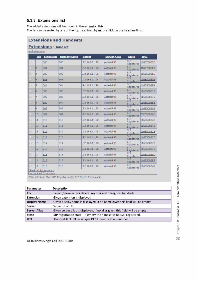
5.3.3 Extensions list
The added extensions will be shown in the extension lists.
The list can be sorted by any of the top headlines, by mouse click on the headline link.
Parameter Description
Idx Select / deselect for delete, register and deregister handsets
Extension Given extension is displayed
Display Name Given display name is displayed. If no name given this field will be empty
Server Server IP or URL
Server Alias Given server alias is displayed. If no alias given this field will be empty.
State SIP registration state – if empty the handset is not SIP registered.
IPEI Handset IPEI. IPEI is unique DECT identification number.

BT Business Single Cell DECT Guide
BT
Bu
sin
ess
DE
CT
Ad
min
istr
ati
on
In
terf
ace
C
ha
pte
r:
21
5.3.3.1 Handset and extension list top/sub-menus
The handset extension list menu is used to control paring or deletion of handset to the system (DECT
registration/de-registrations) and to control SIP registration/de-registrations to the system.
Above and below the list are found commands for making operations on handsets/and extensions. The top
menu is general operations, and the sub menu is always operating on selected handsets/extensions.
Screenshots
In the below table each command is described.
Actions Description
Add extension Access to the “Add extension” sub menu
Stop Registration Manually stop DECT registration mode of the system. This prevents
any handset from registering to the system
Delete Handset(s) Deregister selected handset(s), but do not delete the extension(s).
Register Handset(s) Enable registration mode for the system making it possible to
register at a specific extension (selected by checkbox)
Deregister Handset(s) Deregister the selected handset(s) and delete the extension(s).
5.3.4 Edit Extension
To edit extension use the mouse to click the link of the extension.
Edit extension will open the same configuration possibilities as add extension. Refer to the above add
extension section.
5.3.5 Handset list
The added handsets will be shown in the handset lists.
The list can be sorted by any of the top headlines, by mouse click on the headline link.

BT Business Single Cell DECT Guide
BT
Bu
sin
ess
DE
CT
Ad
min
istr
ati
on
In
terf
ace
C
ha
pte
r:
22
Parameter Description
Idx Select / deselect for delete, register and deregister handsets
IPEI Handset IPEI. IPEI is unique DECT identification number.
Handset state
FW info
FWU Progress Possible FWU progress states:
Off: Means sw version is specified to 0 = fwu is off
Initializing: Means FWU is starting and progress is 0%.
X% : FWU ongoing
Verifying X%: FWU writing is done and now verifying before swap
”Waiting for charger” (HS) / ”Conn. term. wait” (Repeater): All FWU is complete and
is now waiting for handset/repeater restart.
Complete HS/repeater: FWU complete
Error: Not able to fwu e.g. file not found, file not valid etc.
Extension

BT Business Single Cell DECT Guide
BT
Bu
sin
ess
DE
CT
Ad
min
istr
ati
on
In
terf
ace
C
ha
pte
r:
23
5.4 Servers
In this section, we describe the different parameters available in the Servers configurations menu.
Maximum 10 servers can be configured.
Screenshot
Parameter Default value Description
Server Alias Empty Parameter for server alias
NAT
Adaption
Disabled To ensure all SIP messages goes directly to the NAT
gateway in the SIP aware router.
Registrar Empty SIP Server proxy DNS or IP address
Permitted value(s): AAA.BBB.CCC.DDD:<Port-Number>
or <URL>:<Port-Number>
Note: Specifying the Port Number is optional.
Outbound
Proxy
Empty This is a Session Border Controller DNS or IP address (OR
SIP server outbound proxy address)
Set the Outbound proxy to the address and port of
private NAT gateway so that SIP messages sent via the
NAT gateway.
Permitted value(s): AAA.BBB.CCC.DDD or <URL> or
<URL>:<Port-Number>
Examples: “192.168.0.1”, “192.168.0.1:5062”,
“nat.company.com” and “sip:[email protected]:5065”.
Re-
registration
time
600 The “expires” value in SIP REGISTER requests. This value
indicates how long the current SIP registration is valid,
and hence specifies the maximum time between SIP
registrations for the given SIP account.
Permitted value(s): A value below 60 sec is not

BT Business Single Cell DECT Guide
BT
Bu
sin
ess
DE
CT
Ad
min
istr
ati
on
In
terf
ace
C
ha
pte
r:
24
recommended, Maximum value 65636
SIP Session
Timers:
Disabled RFC 4028. A “keep-alive” mechanism for calls. The session
timer value specifies the maximum time between “keep-
alive” or more correctly session refresh signals. If no
session refresh is received when the timer expires the call
will be terminated. Default value is 1800 s according to
the RFC. Min: 90 s. Max: 65636.
If disabled session timers will not be used.
Session
Timer Values
(s):
1800 Default value is 1800s according to the RFC.
If disabled session timers will not be used.
Permitted value(s): Minimum value 90, Maximum 65636
SIP
Transport
UDP Select UDP, TCP, TLS 1.0
Signal TCP
Source Port
Disabled When SIP Transport is set to TCP or TLS, a TCP (or TLS)
connection will be established for each SIP extension. The
source port of the connection will be chosen by the TCP
stack, and hence the local SIP port parameter, specified
within the SIP/RTP Settings will not be used. The “Signal
TCP Source Port” parameter specifies if the used source
port shall be signalled explicitly in the SIP messages.
Use One
TCP/TLS
Connection
per SIP
Extension:
Disabled When using TCP or TLS as SIP transport, choose if a
TCL/TLS connection
shall be established for each SIP extension or if the base
station shall establish one connection which all SIP
extensions use. Please note that if TLS is used and SIP
server requires client authentication (and requests a
client certificate), this setting must be set to disabled.
0: Disabled. (Use one TCP/TLS connection for all SIP
extensions)
1: Enabled. (Use one TCP/TLS connection per SIP
extensions).
Keep Alive Enabled This directive defines the window period (30 sec.) to
keep opening the port of relevant NAT-aware router(s),
etc.
Show
Extension on
Handset Idle
Screen
Enabled If enabled extension will be shown on handset idle
screen.
Hold
Behaviour
RFC 3264 Specify the hold behaviour by handset hold feature.
RFC 3264: Hold is 24nalyse24n according to RFC 3264, i.e.
the connection information part of the SDP contains the
IP Address of the endpoint, and the direction attribute is
send only, recv only or inactive dependant of the context
RFC 2543: The ”old” way of 24nalyse24ng HOLD. The
connection information part of the SDP is set to 0.0.0.0,
and the direction attribute is sendonly, recvonly or
inactive dependant of the context
Attended
Transfer
Behaviour
Hold 2nd
Call When we have two calls, and one call is on hold, it is
possible to perform attended transfer. When the transfer
soft key is pressed in this situation, we have traditionally
also put the active call on hold before the SIP REFER
BT Business Single Cell DECT Guide
BT
Bu
sin
ess
DE
CT
Ad
min
istr
ati
on
In
terf
ace
C
ha
pte
r:
25
request is sent. However, we have experienced that some
PBXs do not expect that the 2nd call is put on hold, and
therefore attended transfer fails on these PBXs.
The "Attended Transfer Behaviour" feature defines
whether or not the 2nd call shall be put on hold before
the REFER is sent.
If "Hold 2nd Call" is selected, the 2nd call will be held
before REFER is sent.
If "Do Not Hold 2nd Call" is selected, the 2nd call will not
be held before the REFER is sent
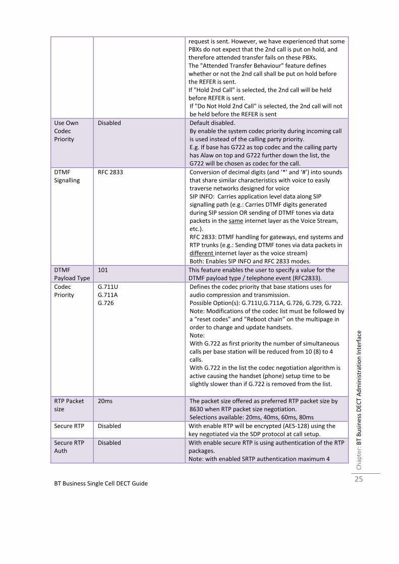
Use Own
Codec
Priority
Disabled Default disabled.
By enable the system codec priority during incoming call
is used instead of the calling party priority.
E.g. If base has G722 as top codec and the calling party
has Alaw on top and G722 further down the list, the
G722 will be chosen as codec for the call.
DTMF
Signalling
RFC 2833 Conversion of decimal digits (and ‘*’ and ‘#’) into sounds
that share similar characteristics with voice to easily
traverse networks designed for voice
SIP INFO: Carries application level data along SIP
signalling path (e.g.: Carries DTMF digits generated
during SIP session OR sending of DTMF tones via data
packets in the same internet layer as the Voice Stream,
etc.).
RFC 2833: DTMF handling for gateways, end systems and
RTP trunks (e.g.: Sending DTMF tones via data packets in
different internet layer as the voice stream)
Both: Enables SIP INFO and RFC 2833 modes.
DTMF
Payload Type
101 This feature enables the user to specify a value for the
DTMF payload type / telephone event (RFC2833).
Codec
Priority
G.711U
G.711A
G.726
Defines the codec priority that base stations uses for
audio compression and transmission.
Possible Option(s): G.711U,G.711A, G.726, G.729, G.722.
Note: Modifications of the codec list must be followed by
a “reset codes” and “Reboot chain” on the multipage in
order to change and update handsets.
Note:
With G.722 as first priority the number of simultaneous
calls per base station will be reduced from 10 (8) to 4
calls.
With G.722 in the list the codec negotiation algorithm is
active causing the handset (phone) setup time to be
slightly slower than if G.722 is removed from the list.
RTP Packet
size
20ms The packet size offered as preferred RTP packet size by
8630 when RTP packet size negotiation.
Selections available: 20ms, 40ms, 60ms, 80ms
Secure RTP Disabled With enable RTP will be encrypted (AES-128) using the
key negotiated via the SDP protocol at call setup.
Secure RTP
Auth
Disabled With enable secure RTP is using authentication of the RTP
packages.
Note: with enabled SRTP authentication maximum 4
BT Business Single Cell DECT Guide
BT
Bu
sin
ess
DE
CT
Ad
min
istr
ati
on
In
terf
ace
C
ha
pte
r:
26
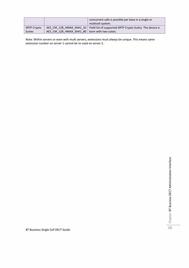
concurrent calls is possible per base in a single or
multicell system.
SRTP Crypto
Suites
AES_CM_128_HMAX_SHA1_32
AES_CM_128_HMAX_SHA1_80
Field list of supported SRTP Crypto Suites. The device is
born with two suites.
Note: Within servers or even with multi servers, extensions must always be unique. This means same
extension number on server 1 cannot be re-used on server 2.

BT Business Single Cell DECT Guide
BT
Bu
sin
ess
DE
CT
Ad
min
istr
ati
on
In
terf
ace
C
ha
pte
r:
27
5.5 Network
In this section, we describe the different parameters available in the network configurations menu.
5.5.1 IP Settings
Screenshot
Parameter Default
Values
Description
DHCP/Static IP DHCP If DHCP is enabled, the device automatically obtains TCP/IP
parameters.
Possible value(s): Static, DHCP
DHCP: IP addresses are allocated automatically from a pool of leased
addresses.
Static IP: IP addresses are manually assigned by the network
administrator.
If the user chooses DHCP option, the other IP settings or options are
not available.
IP Address NA 32-bit IP address of device (e.g. base station). 64-bit IP address will be
supported in the future.
Permitted value(s): AAA.BBB.CCC.DDD
Subnet Mask NA Is device subnet mask.
Permitted value(s): AAA.BBB.CCC.DDD
This is a 32-bit combination used to describe which portion an IP
address refers to the subnet and which part refers to the host.
A network mask helps users know which portion of the address
identifies the network and which portion of the address identifies the
node.
Default Gateway NA Device’s default network router/gateway (32-bit).
Permitted value(s): AAA.BBB.CCC.DDD e.g. 192.168.50.0
IP address of network router that acts as entrance to other network.
This device provides a default route for TCP/IP hosts to use when
communicating with other hosts on hosts networks.
DNS (Primary) NA Main server to which a device directs Domain Name System (DNS)
queries.
Permitted value(s): AAA.BBB.CCC.DDD or <URL>
This is the IP address of server that contains mappings of DNS domain
names to various data, e.g. IP address, etc.
The user needs to specify this option when static IP address option is
chosen.
DNS (Secondary) NA This is an alternate DNS server.
BT Business Single Cell DECT Guide
BT
Bu
sin
ess
DE
CT
Ad
min
istr
ati
on
In
terf
ace
C
ha
pte
r:
28
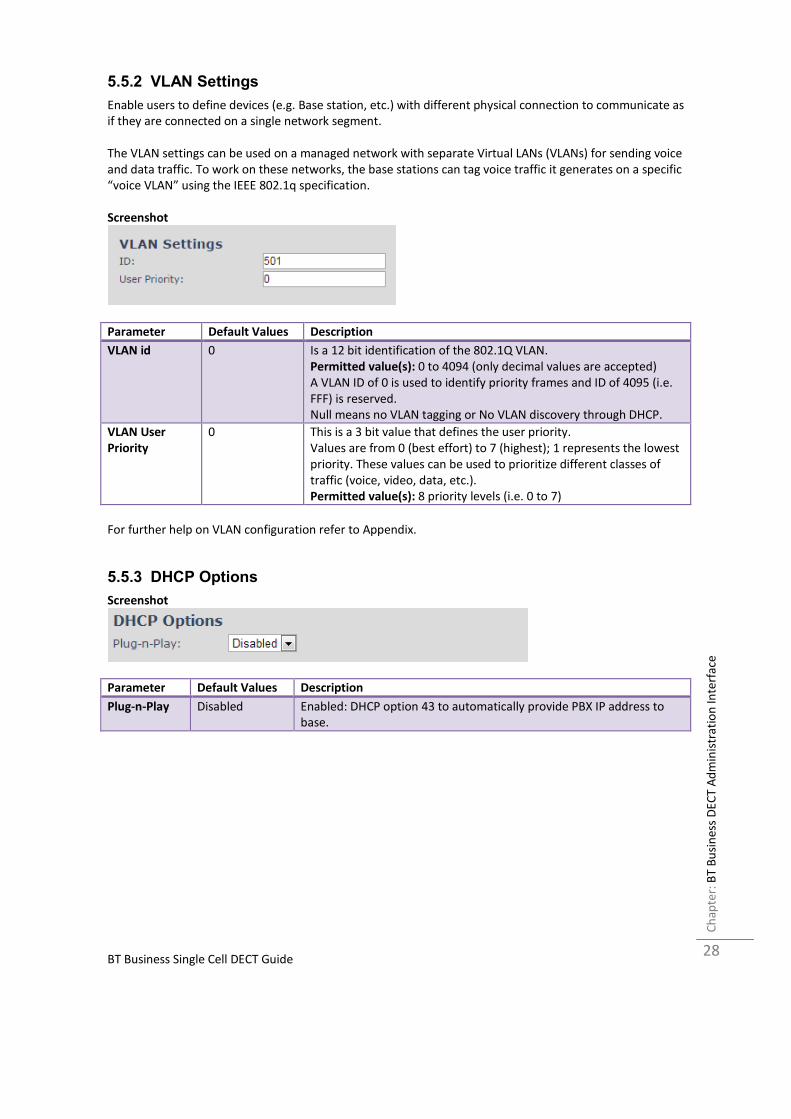
5.5.2 VLAN Settings
Enable users to define devices (e.g. Base station, etc.) with different physical connection to communicate as
if they are connected on a single network segment.
The VLAN settings can be used on a managed network with separate Virtual LANs (VLANs) for sending voice
and data traffic. To work on these networks, the base stations can tag voice traffic it generates on a specific
“voice VLAN” using the IEEE 802.1q specification.
Screenshot
Parameter Default Values Description
VLAN id 0 Is a 12 bit identification of the 802.1Q VLAN.
Permitted value(s): 0 to 4094 (only decimal values are accepted)
A VLAN ID of 0 is used to identify priority frames and ID of 4095 (i.e.
FFF) is reserved.
Null means no VLAN tagging or No VLAN discovery through DHCP.
VLAN User
Priority
0 This is a 3 bit value that defines the user priority.
Values are from 0 (best effort) to 7 (highest); 1 represents the lowest
priority. These values can be used to prioritize different classes of
traffic (voice, video, data, etc.).
Permitted value(s): 8 priority levels (i.e. 0 to 7)
For further help on VLAN configuration refer to Appendix.
5.5.3 DHCP Options
Screenshot
Parameter Default Values Description
Plug-n-Play Disabled Enabled: DHCP option 43 to automatically provide PBX IP address to
base.
BT Business Single Cell DECT Guide
BT
Bu
sin
ess
DE
CT
Ad
min
istr
ati
on
In
terf
ace
C
ha
pte
r:
29
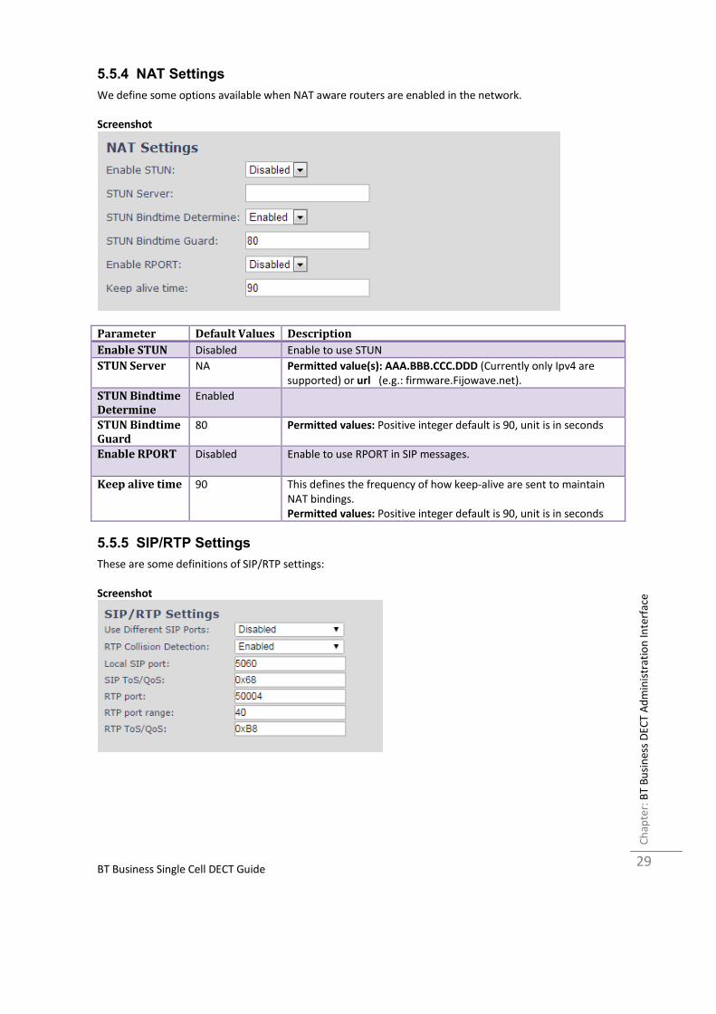
5.5.4 NAT Settings
We define some options available when NAT aware routers are enabled in the network.
Screenshot
Parameter Default Values Description
Enable STUN Disabled Enable to use STUN
STUN Server NA Permitted value(s): AAA.BBB.CCC.DDD (Currently only Ipv4 are
supported) or url (e.g.: firmware.Fijowave.net).
STUN Bindtime
Determine
Enabled
STUN Bindtime
Guard
80 Permitted values: Positive integer default is 90, unit is in seconds
Enable RPORT Disabled Enable to use RPORT in SIP messages.
Keep alive time 90 This defines the frequency of how keep-alive are sent to maintain
NAT bindings.
Permitted values: Positive integer default is 90, unit is in seconds
5.5.5 SIP/RTP Settings
These are some definitions of SIP/RTP settings:
Screenshot

BT Business Single Cell DECT Guide
BT
Bu
sin
ess
DE
CT
Ad
min
istr
ati
on
In
terf
ace
C
ha
pte
r:
30
Parameter Default Values Description
Use Different
SIP Ports
Disabled If disabled, the Local SIP port parameter specifies the source port
used for SIP signalling in the system.
If enabled, the Local SIP Port parameter specifies the source port
used for first user agent (UA) instance. Succeeding UA’s will get
succeeding ports.
RTP
Collision
Detection
Enabled Enable: If two sources with same SSRC, the following one is discarded.
Disabled: No check – device will accept all sources.
Local SIP
port
5060 The source port used for SIP signalling
Permitted values: Port number default 5060.
SIP ToS/QoS 0x68 Priority of call control signalling traffic based on both IP Layers of
Type of Service (ToS) byte. ToS is referred to as Quality of Service
(QoS) in packet based networks.
Permitted values: Positive integer, default is 0x68
RTP port 50004 The first RTP port to use for RTP audio streaming.
Permitted values: Port number default 50004 (depending on the
setup).
RTP port
range
40 The number of ports that can be used for RTP audio streaming.
Permitted values: Positive integers, default is 40
RTP
TOS/QoS
0xB8 Priority of RTP traffic based on the IP layer ToS (Type of Service) byte.
ToS is referred to as Quality of Service (QoS) in packet based
networks.
See RFC 1349 for details. “cost bit” is not supported.
o Bit 7..5 defines precedence.
o Bit 4..2 defines Type of Service.
o Bit 1..0 are ignored.
Setting all three of bit 4..2 will be ignored.
Permitted values: Positive integer, default is 0xB8

BT Business Single Cell DECT Guide
BT
Bu
sin
ess
DE
CT
Ad
min
istr
ati
on
In
terf
ace
C
ha
pte
r:
31
5.6 Management Settings Definitions
The administrator can configure base stations to perform some specific functions such as configuration of
file transfers, firmware up/downgrades, password management, and SIP/debug logs.
Screenshot
Parameter Default value Description
Base Station
Name:
VoIP It indicates the title that appears at the top window of the browser
and is used in the multicell page.
Management
Transfer
Protocol
TFTP The protocol assigned for configuration file and central directory
Valid Input(s): TFTP, HTTP, HTTPs
HTTP
Management
upload script
Empty The folder location or directory path that contains the configuration
files of the Configuration server. The configuration upload script is a
file located in e.g. TFTP server or Apache Server which is also the
configuration server.
Permitted value(s): /<configuration-file-directory>
Example: /CfgUpload
Note: Must begin with (/) slash character. Either / or \ can be used.
HTTP
Management
password
Empty Password that should be entered in order to have access to the
configuration server.
Permitted value(s): 8-bit string length
Configuration Empty Server/device that provides configuration file to base station.

BT Business Single Cell DECT Guide
BT
Bu
sin
ess
DE
CT
Ad
min
istr
ati
on
In
terf
ace
C
ha
pte
r:
32
server
address
Type: DNS or IP address
Permitted value(s): AAA.BBB.CCC.DDD or <URL>
Base Specific
File
Empty Base configuration file
Configuration
File Download
Disabled Base Specific file: Used when configuring a single cell base
Multicell Specific File: Used when configuring a multicell based
system
Base and Multicell Specific File: Used on out of factory bases to
specify VLAN and Multicell ID and settings.
Text
Messaging
Disabled
Text
Messaging &
Alarm server
Empty
Text
Messaging
Port
Empty
Text
Messaging
Keep Alive
(m)
Empty
Text
Messaging
Response (s)
Empty
Text
Messaging
TTL
SIP Log Server
Address
Empty Permitted value(s): AAA.BBB.CCC.DDD or <URL>
Requires a predefined folder named: \SIP
Upload of SIP
Log
Disabled Enable this option to save low level SIP debug messages to the
server. The SIP logs are saved in the file format:
<MAC_Address><Time_Stamp>SIP.log
Syslog Server
IP-Address
NA Permitted value(s): AAA.BBB.CCC.DDD or <URL>
Syslog Server
Port
NA Port number of syslog server.
Syslog Level Off Off: No data is saved on syslog server
Normal Operation: Normal operation events are logged, incoming
call, outgoing calls, handset registration, DECT location, and call lost
due to busy, critical system errors, general system information.
System Analyze: Handset roaming, handset firmware updates status.
The system 32nalyse level also contains the messages from normal
operation.
Debug: Used by Fijowave for debug. Should not be enabled during
normal operation.
Enable
Automatic
Prefix
Disabled Disabled: Feature off.
Enabled: The base will add the leading digit defined in “Set Prefix for
Outgoing Calls”.
Enabled + fall through on * and #: Will enable detection of * or # at
the first digit of a dialled number. In case of detection the base will
not complete the dialled number with a leading 0.
Examples:

BT Business Single Cell DECT Guide
BT
Bu
sin
ess
DE
CT
Ad
min
istr
ati
on
In
terf
ace
C
ha
pte
r:
33
1: dialed number on handset * 1234 - > dialed number to the pabx
*1234
2: dialed number on handset #1234 - > dialed number to the pabx
#1234
3: dialed number on handset 1234 - > dialed number to the pabx
01234
Set Maximum
Digits of
Internal
Numbers
0 Used to detect internal numbers. In case of internal numbers no
prefix number will be added to the dialled number.
Set Prefix for
Outgoing Calls
Empty Prefix number for the enabled automatic prefix feature.
Permitted value(s): 1 to 9999
There are three ways of configuring the system.
1. Manual configuration by use of the Web server in the base station(s)
2. By use of configuration files that are uploaded from a disk via the “Configuration” page on the Web
server.
3. By use of configuration files which the base station(s) download(s) from a configuration server.

BT Business Single Cell DECT Guide
BT
Bu
sin
ess
DE
CT
Ad
min
istr
ati
on
In
terf
ace
C
ha
pte
r:
34
5.7 Time Server
In this section, we describe the different parameters available in the Time Server menu.
The Time server supplies the time used for data synchronisation in a multi-cell configuration. As such it is
mandatory for a multi-cell configuration. The system will not work without a time server configured.
As well the time server is used in the debug logs and for SIP traces information pages, and used to
determine when to check for new configuration and firmware files.
NOTE: It is not necessary to set the time server for standalone base stations (optional).
Press the “Time PC” button to grab the current PC time and use in the time server fields.
NOTE:
When time server parameters are modified/changed synchronisation between base stations can take up to
15 minutes before all base stations are synchronised, depending on the number of base stations in the
system.
Screenshot

BT Business Single Cell DECT Guide
BT
Bu
sin
ess
DE
CT
Ad
min
istr
ati
on
In
terf
ace
C
ha
pte
r:
35
Parameter Default Values Description
Time Server Empty DNS name or IP address of NTP server.
Enter the IP/DNS address of the server that distributes
reference clock information to its clients including Base
stations, Handsets, etc.
Valid Input(s): AAA.BBB.CCC.DDD or URL (e.g. time.server.com)
Currently only Ipv4 address (32-bit) nomenclature is supported.
Allow broadcast
NTP
Checked
Refresh time (h) Empty The window time in seconds within which time server
refreshes.
Valid Inputs: positive integer
Set timezone by
country/region
Checked By checked country setting is used (refer to country web page).
Time Zone 0 Refers to local time in GMT or UTC format.
Min: -12:00
Max: +13:00
Daylight Saving
Time (DST)
Disabled The system administrator can Enable or Disable DST manually.
Automatic: Enter the start and stop dates if you select
Automatic.
DST Fixed By Day Use Month and
Date
You determine when DST actually changes. Choose the
relevant date or day of the week, etc. from the drop down
menu.
DST Start Month March Month that DST begins
Valid Input(s): Gregorian months (e.g. January, February, etc.)
DST Start Date 25 Numerical day of month DST comes to effect when DST is fixed
to a specific date
Valid Inputs: positive integer
DST Start Time 3 DST start time in the day
Valid Inputs: positive integer
DST Start Day of
Week
Monday Day within the week DST begins
DST Start Day of
Week, Last in Month
Last in Month Specify the week that DST will actually start.
DST Stop Month October The month that DST actually stops.
DST Stop Date 1 The numerical day of month that DST turns off.
Valid Inputs: positive integer (1 to 12)
DST Stop Time 2 The time of day DST stops
Valid Inputs: positive integer (1 to 12)
DST Stop Day of
Week
Sunday The day of week DST stops
DST Stop Day of
Week Last in Month
First in Month The week within the month that DST will turn off.

BT Business Single Cell DECT Guide
BT
Bu
sin
ess
DE
CT
Ad
min
istr
ati
on
In
terf
ace
C
ha
pte
r:
36
5.8 Country
The country setting controls the in-band tones used by the system. To select web interface language go to
the management page.
Screenshot
Parameter Default Values Description
Select Country Germany Supported countries: Australia, Belgium, Brazil, Denmark,
Germany, Spain, France, Ireland, Italia, Luxembourg,
Nederland, New Zealand, Norway, Portugal, Swiss, Finland,
Sweden, Turkey, United Kingdom, US/Canada, Austria
State / Region NA Only shown by country selection US/Canada, Australia, Brazil
Select Language English Web interface language. Number of available languages:
English, Dansk, Italiano, Tyrkie, Deutsch, Portuguese, Hrvatski,
Srpski, Slovenian, Nederlands, Francaise, Espanol, Russian,
Polski.
Set timezone by
country/region
checked When checked timezone will follow country/region
Set DST by
country/region
checked When checked DST will follow country/region
Notes Empty Only showing notes to time setting for countries: US/Canada,
Brazil
NOTE: By checked timezone and DST the parameters in web page Time will be discarded.
The following types of in-band tones are supported:
- Dial tone
- Busy tone
- Ring Back tone
- Call Waiting tone
- Re-order tone

BT Business Single Cell DECT Guide
BT
Bu
sin
ess
DE
CT
Ad
min
istr
ati
on
In
terf
ace
C
ha
pte
r:
37
5.9 Security
The security section is used for loading of certificates and for selecting if only trusted certificates are used.
Furthermore, web password can be configured.
The Security web is divided into three sections: Certificates (trusted), SIP Client Certificates (and keys) and
Password administration.
To setup secure fwu and configuration file download select HTTPs for the Management Transfer Protocol
(reference 0)
SIP and RTP security is server dependent and in order to configure user must use the web option Servers
(reference 5.4).
5.9.1 Certificates
The certificates list contains the list of loaded certificates for the system. Using the left column check mark
it is possible to check and delete certificates. To import a new certificate use the mouse “select file” and
browse to the selected file. When file is selected, use the “Load” bottom to load the certificate.
The certificate format supported is DER encoded binary X.509 (.cer).
Screenshot
Certificates list
Parameter Default Values Description
Idx Fixed indexes Index number
Issued To Empty IP address – which is part of the certificate file
Issued To Empty Organisation, Company – which is part of the certificate file
Valid Until Empty Date Time Year – which is part of the certificate file
Screenshot
By enabling Use Only Trusted Certificates, the certificates the base will receive from the server must be
valid and loaded into the system. If no valid matching certificate is found during the TLS connection
establishment, the connection will fail. When Use Only Trusted Certificates is disabled, all certificates
received from the server will be accepted.

BT Business Single Cell DECT Guide
BT
Bu
sin
ess
DE
CT
Ad
min
istr
ati
on
In
terf
ace
C
ha
pte
r:
38
5.9.2 SIP Client Certificates
To be able to establish a TLS connection in scenarios where the server requests a client certificate, a
certificate/key pair must be loaded into the base. This is currently supported only for SIP.
To load a client certificate/key pair, both files must be selected at the same time, and it is done by pressing
“select files” under “Import SIP Client Certificate and Key Pair” and then select the certificate file as well as
the key file at the same time. Afterwards, press load.
The certificate must be provided as a DER encoded binary X.509 (.cer) file, and the key must be provided as
a binary PKCS#8 file.
Note: Use Chrome for loading SIP Client Certificates
Screenshot
5.9.3 Password
In the below the password parameters are defined.
Screenshot
Parameter Default Values Description
Username Admin Can be modified to any supported character and number
Current Password Admin Can be modified to any supported character and number
New Password Empty Change to new password
Confirm Password Empty Confirm password to reduce accidental changes of passwords
Password valid special signs: @/|<>-_:.!?*+#
Password valid numbers: 0-9
Password valid letters: a-z and A-Z

BT Business Single Cell DECT Guide
BT
Bu
sin
ess
DE
CT
Ad
min
istr
ati
on
In
terf
ace
C
ha
pte
r:
39
5.10 Repeaters Within this section we describe the repeater parameter, and how to operate the repeater.
5.10.1 Add repeater
From repeaters web select “Add Repeater”
Screenshot
Then select “DECT Sync mode”
Screenshot

BT Business Single Cell DECT Guide
BT
Bu
sin
ess
DE
CT
Ad
min
istr
ati
on
In
terf
ace
C
ha
pte
r:
40
5.10.1.1 Manually
User controlled by manually assign “Repeater RPN” and “DECT sync source RPN”. The parameters are
selected from the drop down menu.
Screenshot
Parameters Description
Idx System counter
RPN
SINGLE CELL SYSTEM:
The base is always RPN00, first repeater will then be RPN01, second repeater
RPN02 and third RPN03 (3 repeaters maximum per base)
DECT sync source
Select the base or repeater the repeater has to be synchronized to.

BT Business Single Cell DECT Guide
BT
Bu
sin
ess
DE
CT
Ad
min
istr
ati
on
In
terf
ace
C
ha
pte
r:
41
5.10.2 Register Repeater
Adding a repeater makes it possible to register the repeater. Registration is made by selecting the repeater
and pressing register repeater. The base window for repeater registration will be open until the registration
is stopped. By stopping the registration all registration on the system will be stopped including handset
registration.
5.10.3 Repeaters list
Parameters Description
IDx Repeater unit identity in the chained network.
Permitted Output: Positive Integers
RPN The Radio Fixed Part Number is an 8-bit DECT cell identity allocated by the
installer. The allocated RPN within the must be geographically unique.
Permitted Output: 0 to 255 (DEC) OR 0x00 to 0xFF (HEX)
Name/IPEI Contains the name and the unique DECT serial number of the repeater. If name is
given the field will be empty.
DECT sync
Source
The “multi cell chain” connection to the specific Base/repeater unit. Maximum
number of chain levels is 12.
Sync. source format: “RPNyy (-zz dBm)”
yy: RPN of source
zz: RSSI level seen from the actual repeater
DECT sync Mode Manually: User controlled by manually assign “Repeater RPN” and “DECT sync
source RPN”
Local Automatical: Repeater controlled by auto detects best base signal and auto
assign RPN.
State Present@unit means connected to unit with RPN yy
FW info Firmware version

BT Business Single Cell DECT Guide
BT
Bu
sin
ess
DE
CT
Ad
min
istr
ati
on
In
terf
ace
C
ha
pte
r:
42
FWU Progress Possible FWU progress states:
Off: Means sw version is specified to 0 = fwu is off
Initializing: Means FWU is starting and progress is 0%.
X% : FWU ongoing
Verifying X%: FWU writing is done and now verifying before swap
”Conn. term. wait” (Repeater): All FWU is complete and is now waiting for
connections to stop before repeater restart.
Complete HS/repeater: FWU complete
Error: Not able to fwu e.g. file not found, file not valid etc.
BT Business Single Cell DECT Guide
Fu
nct
ion
alit
y O
ve
rvie
w
Ch
ap
ter:
43
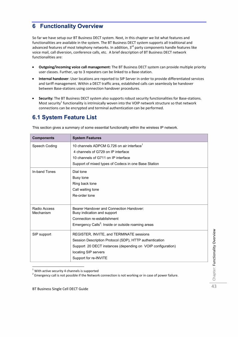
6 Functionality Overview
So far we have setup our BT Business DECT system. Next, in this chapter we list what features and
functionalities are available in the system. The BT Business DECT system supports all traditional and
advanced features of most telephony networks. In addition, 3rd
party components handle features like
voice mail, call diversion, conference calls, etc. A brief description of BT Business DECT network
functionalities are:
• Outgoing/incoming voice call management: The BT Business DECT system can provide multiple priority
user classes. Further, up to 3 repeaters can be linked to a Base-station.
• Internal handover: User locations are reported to SIP Server in order to provide differentiated services
and tariff management. Within a DECT traffic area, established calls can seamlessly be handover
between Base-stations using connection handover procedures.
• Security: The BT Business DECT system also supports robust security functionalities for Base-stations.
Most security1 functionality is intrinsically woven into the VOIP network structure so that network
connections can be encrypted and terminal authentication can be performed.
6.1 System Feature List
This section gives a summary of some essential functionality within the wireless IP network.
Components System Features
Speech Coding 10 channels ADPCM G.726 on air interface1
4 channels of G729 on IP interface
10 channels of G711 on IP interface
Support of mixed types of Codecs in one Base Station
In-band Tones Dial tone
Busy tone
Ring back tone
Call waiting tone
Re-order tone
Radio Access Mechanism
Bearer Handover and Connection Handover: Busy indication and support
Connection re-establishment
Emergency Calls2: Inside or outside roaming areas
SIP support REGISTER, INVITE, and TERMINATE sessions
Session Description Protocol (SDP), HTTP authentication
Support 20 DECT instances (depending on VOIP configuration)
locating SIP servers
Support for re-INVITE
1 With active security 4 channels is supported
2 Emergency call is not possible if the Network connection is not working or in case of power failure.
BT Business Single Cell DECT Guide
Fu
nct
ion
alit
y O
ve
rvie
w
Ch
ap
ter:
44
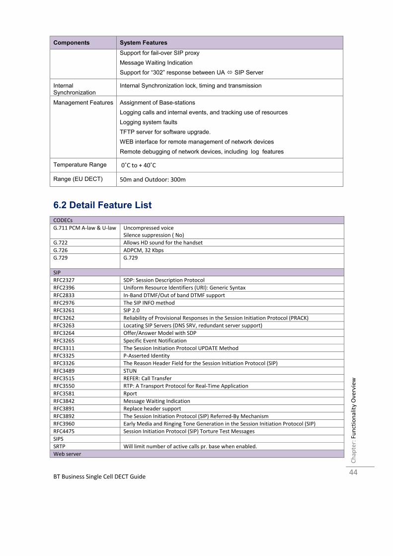
Components System Features
Support for fail-over SIP proxy
Message Waiting Indication
Support for “302” response between UA � SIP Server
Internal Synchronization
Internal Synchronization lock, timing and transmission
Management Features Assignment of Base-stations
Logging calls and internal events, and tracking use of resources
Logging system faults
TFTP server for software upgrade.
WEB interface for remote management of network devices
Remote debugging of network devices, including log features
Temperature Range 0˚C to + 40˚C
Range (EU DECT) 50m and Outdoor: 300m
6.2 Detail Feature List
CODECs
G.711 PCM A-law & U-law Uncompressed voice
Silence suppression ( No)
G.722 Allows HD sound for the handset
G.726 ADPCM, 32 Kbps
G.729 G.729
SIP
RFC2327 SDP: Session Description Protocol
RFC2396 Uniform Resource Identifiers (URI): Generic Syntax
RFC2833 In-Band DTMF/Out of band DTMF support
RFC2976 The SIP INFO method
RFC3261 SIP 2.0
RFC3262 Reliability of Provisional Responses in the Session Initiation Protocol (PRACK)
RFC3263 Locating SIP Servers (DNS SRV, redundant server support)
RFC3264 Offer/Answer Model with SDP
RFC3265 Specific Event Notification
RFC3311 The Session Initiation Protocol UPDATE Method
RFC3325 P-Asserted Identity
RFC3326 The Reason Header Field for the Session Initiation Protocol (SIP)
RFC3489 STUN
RFC3515 REFER: Call Transfer
RFC3550 RTP: A Transport Protocol for Real-Time Application
RFC3581 Rport
RFC3842 Message Waiting Indication
RFC3891 Replace header support
RFC3892 The Session Initiation Protocol (SIP) Referred-By Mechanism
RFC3960 Early Media and Ringing Tone Generation in the Session Initiation Protocol (SIP)
RFC4475 Session Initiation Protocol (SIP) Torture Test Messages
SIPS
SRTP Will limit number of active calls pr. base when enabled.
Web server

BT Business Single Cell DECT Guide
Fu
nct
ion
alit
y O
ve
rvie
w
Ch
ap
ter:
45
Embedded web server HTTP/HTTPS
Other features
Quality of service Type of Service (ToS) including DiffServ Tagging, and QoS per IEEE 802.1p/q
IP Quality Warning – Network outage, VoIP service outage
Adaptive Jitter Buffer support
Automatic DST
Tone Scheme Country Depend Tone Scheme
Ethernet features
VLAN VLAN (802.1p/q)
DHCP Support
Static IP
TLS 1.0 For secure connections (AES 128)
TFTP For configuration download.
HTTP For configuration download.
HTTPS For secure configuration download.
TCP/IP/UDP
SNTP For internet clock synchronization
Quality of service Type of Service (ToS) including DiffServ Tagging, and QoS per IEEE 802.1p/q
DHCP option 66
DNS srv
DECT
DECT CAP Connectionless handover, enhanced location registration
CAT-IQ v1.0 Wideband Speech
General Telephony
Handset Support 20 handsets supported (single cell)
VoIP Accounts 20 VoIP accounts per base
Simultaneous Calls 6 simultaneous calls per base station
Call features Codec Negotiation
Codec Switching
Missed call notification
Voice message waiting notification
Date and Time synchronization
Parallel calls
Common parallel call procedures
Call transfer unannounced
Call transfer announced
Conference
Call Waiting
Calling line identity restriction
Outgoing call
Call Toggle
Incoming call
Line identification
Multiple Lines
Multiple calls
Call identification
Calling Name Identification Presentation (CNIP)
Calling Line Identification Presentation (CLIP)
Call Hold
List of registered handsets
Call log 50 mixed between Incoming, outgoing, missed calls
Phone Book Common Phonebook with up to 3000 entries (Import via csv format)
Common Phonebook LDAP V2.0
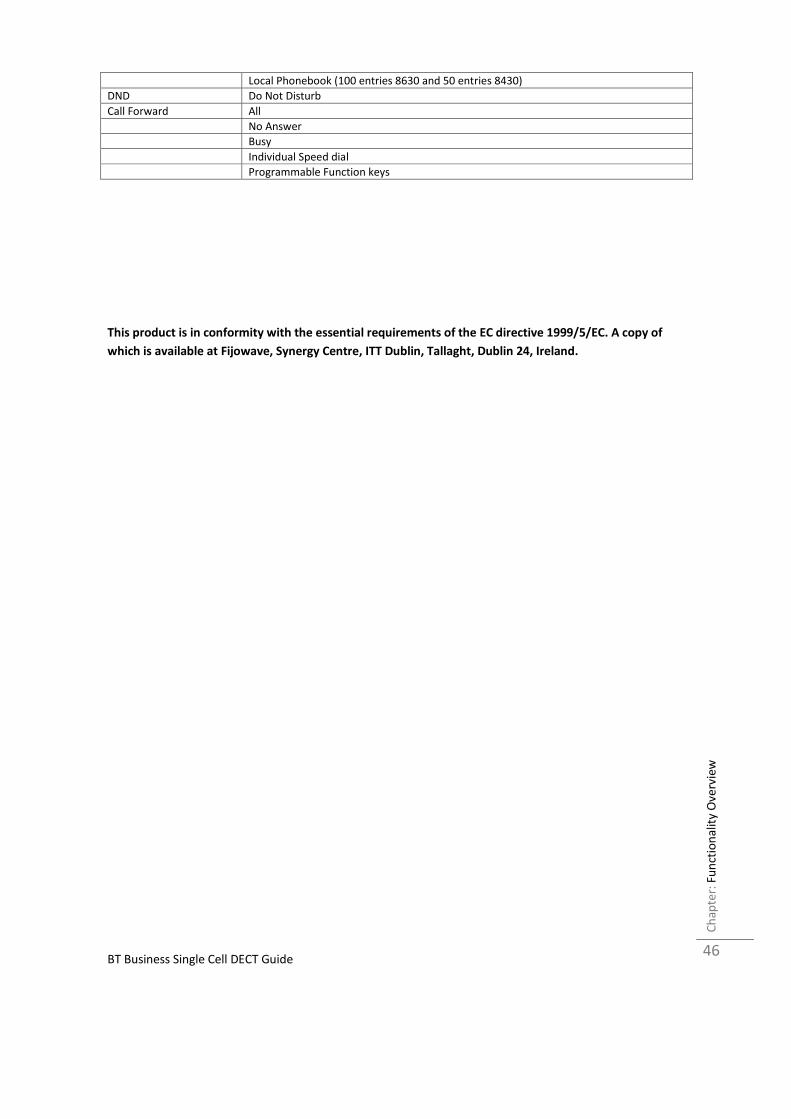
BT Business Single Cell DECT Guide
Fu
nct
ion
alit
y O
ve
rvie
w
Ch
ap
ter:
46
Local Phonebook (100 entries 8630 and 50 entries 8430)
DND Do Not Disturb
Call Forward All
No Answer
Busy
Individual Speed dial
Programmable Function keys
This product is in conformity with the essential requirements of the EC directive 1999/5/EC. A copy of
which is available at Fijowave, Synergy Centre, ITT Dublin, Tallaght, Dublin 24, Ireland.


