
USER'S MANUAL FOR
BRIDGE ANALYSIS AND RATING (BAR7)
Version 7.15.0.0

BRIDGE ANALYSIS AND RATING
This page is intentionally left blank
USER'S MANUAL FOR COMPUTER PROGRAM BAR7
BRIDGE ANALYSIS AND RATING
Version 7.15.0.0
Prepared by:
Pennsylvania Department of Transportation Bureau of Business Solutions and Services
Engineering Software Section
February 2018
Copyright © 1990-2018 Commonwealth of Pennsylvania Department of Transportation

BRIDGE ANALYSIS AND RATING
ii
This page is intentionally left blank
BRIDGE ANALYSIS AND RATING
iii
TABLE OF CONTENTS
CHAPTER 1 GENERAL DESCRIPTION ............................................................................................................... 1-1 PROGRAM IDENTIFICATION ............................................................................................................... 1-1 ABBREVIATIONS .................................................................................................................................. 1-2
CHAPTER 2 PROGRAM DESCRIPTION .............................................................................................................. 2-1 GENERAL .............................................................................................................................................. 2-1 RATINGS DEFINED ............................................................................................................................... 2-2
2.2.1 Inventory Rating (Design) ............................................................................................................. 2-2 2.2.2 Operating Rating (Design) ............................................................................................................ 2-2 2.2.3 Safe Load Capacity ...................................................................................................................... 2-2 2.2.4 Inventory Rating (Loaded) ............................................................................................................ 2-2 2.2.5 Operating Rating (Loaded) ........................................................................................................... 2-2
BRIDGE TYPES ..................................................................................................................................... 2-3 LIVE LOADINGS .................................................................................................................................. 2-10
CHAPTER 3 METHOD OF SOLUTION ................................................................................................................. 3-1 NOTATIONS........................................................................................................................................... 3-2 SECTION PROPERTIES ....................................................................................................................... 3-7
3.2.1 R. C. Slab and Precast Concrete Slab ......................................................................................... 3-7 3.2.2 R. C. T-Beam ................................................................................................................................ 3-7 3.2.3 Girder, Floorbeam or Stringer ..................................................................................................... 3-10 3.2.4 Encased I-Beam ......................................................................................................................... 3-13 3.2.5 Truss Member............................................................................................................................. 3-13
CONTINUOUS STRUCTURE ANALYSIS ........................................................................................... 3-14 3.3.1 Continuous Girder ...................................................................................................................... 3-14 3.3.2 Continuous Truss ....................................................................................................................... 3-14 3.3.3 Cantilever Truss ......................................................................................................................... 3-15
DEAD LOAD ANALYSIS ...................................................................................................................... 3-16 3.4.1 Girder .......................................................................................................................................... 3-16 3.4.2 Stringer ....................................................................................................................................... 3-16 3.4.3 Concrete Slab or T-Beam ........................................................................................................... 3-16 3.4.4 Encased I-Beam ......................................................................................................................... 3-17 3.4.5 Truss ........................................................................................................................................... 3-17 3.4.6 Floorbeam ................................................................................................................................... 3-17 3.4.7 Patch Load.................................................................................................................................. 3-18
LIVE LOAD ANALYSIS ........................................................................................................................ 3-19 3.5.1 Beam, Stringer or Girder ............................................................................................................ 3-19 3.5.2 Floorbeam ................................................................................................................................... 3-19 3.5.3 Truss ........................................................................................................................................... 3-23 3.5.4 Influence Line ............................................................................................................................. 3-23 3.5.5 Live Load Distribution ................................................................................................................. 3-27 3.5.6 Impact ......................................................................................................................................... 3-29 3.5.7 Redistribution of Moments .......................................................................................................... 3-30
SECTION CAPACITY .......................................................................................................................... 3-32 3.6.1 Allowable Stresses ..................................................................................................................... 3-32 3.6.2 Flexural Steel Member ............................................................................................................... 3-32 3.6.3 Flexural Concrete Member ......................................................................................................... 3-33 3.6.4 Truss Members ........................................................................................................................... 3-34
MAXIMUM STRENGTH ....................................................................................................................... 3-37 3.7.1 Flexural Strength of Steel Member ............................................................................................. 3-37 3.7.2 Shear Strength of Steel Member ................................................................................................ 3-38 3.7.3 Overload Moment Strength of Steel Members ........................................................................... 3-48
BRIDGE ANALYSIS AND RATING
iv
3.7.4 Flexural Strength of Concrete Members .................................................................................... 3-48 3.7.5 Shear Strength of Concrete Members ........................................................................................ 3-49 3.7.6 Stresses ...................................................................................................................................... 3-49 3.7.7 Limiting Bending Stress .............................................................................................................. 3-49 3.7.8 Shear Strength of Encased I-beam ............................................................................................ 3-49 3.7.9 Axial Capacities of Truss Members ............................................................................................ 3-50
LIVE LOAD RATINGS .......................................................................................................................... 3-53 3.8.1 Flexural Steel Members .............................................................................................................. 3-53 3.8.2 Flexural Concrete Members ....................................................................................................... 3-57 3.8.3 Truss Members ........................................................................................................................... 3-60
DEFLECTIONS .................................................................................................................................... 3-63 3.9.1 Simple Span Beam or Girder ...................................................................................................... 3-63 3.9.2 Continuous Span Girder ............................................................................................................. 3-63 3.9.3 Truss ........................................................................................................................................... 3-63
FATIGUE LIFE ESTIMATION .............................................................................................................. 3-64 3.10.1 Girder .......................................................................................................................................... 3-64 3.10.2 Truss ........................................................................................................................................... 3-66
GUSSET PLATE ANALYSIS AND OPERATING RATINGS ............................................................... 3-69 3.11.1 Notes .......................................................................................................................................... 3-69 3.11.2 General ....................................................................................................................................... 3-70 3.11.3 Shear Capacity ........................................................................................................................... 3-70 3.11.4 Capacity Equations to Analyze Gusset Plates at the End of All Members for Tension and at the End of the Diagonal and Vertical chords for Compression ..................................................................... 3-71 3.11.5 Block Shear Rupture Capacity for Any Member Connection at a Joint...................................... 3-73 3.11.6 Connection Capacities ................................................................................................................ 3-74 3.11.7 Unsupported Edge in Compression Adequacy Check ............................................................... 3-75 3.11.8 Operating Level Rating Equations .............................................................................................. 3-75
PONY TRUSS STABILITY CHECK ..................................................................................................... 3-78 3.12.1 Notes .......................................................................................................................................... 3-78 3.12.2 General ....................................................................................................................................... 3-78 3.12.3 Logic ........................................................................................................................................... 3-78 3.12.4 Lookup Table for K Values ......................................................................................................... 3-79 3.12.5 Transverse-frame Spring Constant ............................................................................................ 3-80 3.12.6 Computation of Pc ...................................................................................................................... 3-81 3.12.7 K Values ..................................................................................................................................... 3-81
BOX-SHAPED CROSS GIRDER WORKAROUND ............................................................................. 3-82 3.13.1 Section Properties ...................................................................................................................... 3-82 3.13.2 Flexure ........................................................................................................................................ 3-82 3.13.3 Shear .......................................................................................................................................... 3-83 3.13.4 Torsion ........................................................................................................................................ 3-83 3.13.5 Summary .................................................................................................................................... 3-83
ASSUMPTIONS AND LIMITATIONS ................................................................................................... 3-85
CHAPTER 4 GETTING STARTED ........................................................................................................................ 4-1 INSTALLATION ...................................................................................................................................... 4-1 PREPARING INPUT .............................................................................................................................. 4-2 ENGINEERING ASSISTANT ................................................................................................................. 4-2 RUNNING THE PROGRAM WITHOUT ENGINEERING ASSISTANT ................................................. 4-2
CHAPTER 5 INPUT DATA REQUIREMENTS ...................................................................................................... 5-1 GENERAL .............................................................................................................................................. 5-1
5.1.1 Input Forms................................................................................................................................... 5-7 PROJECT IDENTIFICATION ............................................................................................................... 5-20 BRIDGE CROSS SECTION AND LOADING ....................................................................................... 5-30 UNSYMMETRICAL PIER SUPPORT CONFIGURATION ................................................................... 5-42 SPAN LENGTHS .................................................................................................................................. 5-43

BRIDGE ANALYSIS AND RATING
v
HINGE LOCATIONS ............................................................................................................................ 5-44 TRAFFIC LANE LOCATIONS .............................................................................................................. 5-44 STRINGER SPAN LENGTHS .............................................................................................................. 5-47 STRINGER LOCATIONS ..................................................................................................................... 5-49 CONCRETE MEMBER PROPERTIES ................................................................................................ 5-51 STIRRUP DETAILS .............................................................................................................................. 5-55 TRUSS GEOMETRY ............................................................................................................................ 5-56 TRUSS DEAD LOADS ......................................................................................................................... 5-64 TRUSS MEMBER PROPERTIES ........................................................................................................ 5-65 ADDITIONAL TRUSS MEMBER PROPERTIES FOR LOAD FACTOR METHOD ............................. 5-70 STEEL MEMBER PROPERTIES ......................................................................................................... 5-73 LATERAL BRACE POINTS AND STIFFENER SPACINGS ................................................................ 5-82 FATIGUE DATA ................................................................................................................................... 5-86 GIRDER FATIGUE DETAIL ................................................................................................................. 5-88 GROSS VEHICLE WEIGHT DISTRIBUTION ...................................................................................... 5-89 SPECIAL LIVE LOADING .................................................................................................................... 5-90
5.21.1 Lane Loading .............................................................................................................................. 5-90 5.21.2 Truck Load .................................................................................................................................. 5-92
GUSSET PLATE PROPERTIES .......................................................................................................... 5-94 GUSSET PLATE MEMBER PROPERTIES ....................................................................................... 5-102 CONCENTRATED PATCH LOADS ................................................................................................... 5-104 DISTRIBUTED PATCH LOADS ......................................................................................................... 5-107
CHAPTER 6 DESCRIPTION OF OUTPUT ............................................................................................................ 6-1 BRIDGE TYPE “CPL”, “CSL”, OR “CTB” ............................................................................................... 6-3
6.1.1 Concrete Section Properties......................................................................................................... 6-3 6.1.2 Maximum Reactions ..................................................................................................................... 6-3 6.1.3 Moment, Shear, Flexural Stress, Shear Stress, and Deflection at Each Section for Each Live Load 6-4 6.1.4 Moment Capacity, Shear Capacity, and Rating Factors at Each Section for Each Live Load ..... 6-5 6.1.5 Moment Capacity, Shear Capacity, and Rating Factors at Critical Sections for Each Live Load 6-5 6.1.6 Rating Summary ........................................................................................................................... 6-5 6.1.7 Influence Line ............................................................................................................................... 6-6
BRIDGE TYPE "EIB" OR "GGG" ........................................................................................................... 6-8 6.2.1 Dead Loads Acting on Girder ....................................................................................................... 6-8 6.2.2 Girder Section Properties ............................................................................................................. 6-8 6.2.3 Deflections .................................................................................................................................. 6-10 6.2.4 Girder – Live Load Xxxx ............................................................................................................. 6-10 6.2.5 Fatigue Life Analysis .................................................................................................................. 6-14 6.2.6 Rating Summary ......................................................................................................................... 6-16 6.2.7 Influence Line ............................................................................................................................. 6-17
BRIDGE TYPE "FSS”, GFF", "GFS", OR "GGF" ................................................................................. 6-19 6.3.1 Girder Analysis ........................................................................................................................... 6-19 6.3.2 Stringer Analysis ......................................................................................................................... 6-20 6.3.3 Floorbeam Analysis .................................................................................................................... 6-20 6.3.4 Fatigue Life Analysis .................................................................................................................. 6-25 6.3.5 Rating Summary ......................................................................................................................... 6-25
BRIDGE TYPE "TFF", “TFS”, OR "TTT" .............................................................................................. 6-27 6.4.1 Member Forces and Allowable Stress Ratings .......................................................................... 6-27 6.4.2 Member Strength and Load Factor Ratings ............................................................................... 6-28 6.4.3 Support Reactions ...................................................................................................................... 6-29 6.4.4 Panel Point Deflections .............................................................................................................. 6-29 6.4.5 Influence Line ............................................................................................................................. 6-30 6.4.6 Fatigue Life Estimation ............................................................................................................... 6-31 6.4.7 Pony Truss Stability Check ......................................................................................................... 6-32
GUSSET PLATE ANALYSIS AND OPERATING RATINGS ............................................................... 6-34 6.5.1 DL & LL Forces and Angles - Part 1, 2, and 3 of 3 (LL = …) ..................................................... 6-34

BRIDGE ANALYSIS AND RATING
vi
6.5.2 Shear At Section A-A: LL Match DL (LL = …) ............................................................................ 6-34 6.5.3 Shear At Section A-A: LL Compressive (LL = …) ...................................................................... 6-35 6.5.4 Shear At Section A-A: LL Tensile (LL = …) ................................................................................ 6-35 6.5.5 Shear At Section B-B: LL Match DL (LL = …) ............................................................................ 6-35 6.5.6 Shear At Section B-B: LL Compressive (LL = …) ...................................................................... 6-35 6.5.7 Shear At Section B-B: LL Tensile (LL = …) ................................................................................ 6-35 6.5.8 Shear At Section C-C: LL Match DL (LL = …) ........................................................................... 6-36 6.5.9 Shear At Section C-C: LL Compressive (LL = …) ...................................................................... 6-36 6.5.10 Shear At Section C-C: LL Tensile (LL = …) ............................................................................... 6-36 6.5.11 Tension and Compression: LL Match DL (LL = …) .................................................................... 6-36 6.5.12 Tension and Compression: LL Compressive (LL = …) .............................................................. 6-37 6.5.13 Tension and Compression: LL Tensile (LL = …) ........................................................................ 6-37 6.5.14 Block Shear: LL Match DL (LL = …) ........................................................................................... 6-37 6.5.15 Block Shear: LL Compressive (LL = …) ..................................................................................... 6-37 6.5.16 Block Shear: LL Tensile (LL = …) .............................................................................................. 6-38 6.5.17 Connections: LL Match DL (LL = …) .......................................................................................... 6-38 6.5.18 Connections: LL Compressive (LL = …) .................................................................................... 6-38 6.5.19 Connections: LL Tensile (LL = …) .............................................................................................. 6-38 6.5.20 Summary Part 1 of 3: LL Match DL (LL = …) ............................................................................ 6-39 6.5.21 Summary Part 1 of 3: LL Compressive (LL = …) ...................................................................... 6-39 6.5.22 Summary Part 1 of 3: LL Tensile (LL = …) ................................................................................ 6-40 6.5.23 Summary Part 2 of 3: LL Match DL (LL = …) ............................................................................ 6-40 6.5.24 Summary Part 2 of 3: LL Compressive (LL = …) ...................................................................... 6-41 6.5.25 Summary Part 2 of 3: LL Tensile (LL = …) ................................................................................ 6-41 6.5.26 Summary Part 3 of 3: LL Match DL (LL = …) ............................................................................ 6-41 6.5.27 Summary Part 3 of 3: LL Compressive (LL = …) ...................................................................... 6-41 6.5.28 Summary Part 3 of 3: LL Tensile (LL = …) ................................................................................ 6-41 6.5.29 Governing Operating Ratings: All Cases, LL = … ..................................................................... 6-42
CHAPTER 7 EXAMPLE PROBLEMS ................................................................................................................... 7-1 EXAMPLE PROBLEM 1 ......................................................................................................................... 7-2
7.1.1 Problem Description ..................................................................................................................... 7-2 7.1.2 Input .............................................................................................................................................. 7-2
EXAMPLE PROBLEM 2 ......................................................................................................................... 7-8 7.2.1 Problem Description ..................................................................................................................... 7-8 7.2.2 Input .............................................................................................................................................. 7-8
EXAMPLE PROBLEM 3 ....................................................................................................................... 7-16 7.3.1 Problem Description ................................................................................................................... 7-16 7.3.2 Input ............................................................................................................................................ 7-16
EXAMPLE PROBLEM 4 ....................................................................................................................... 7-27 7.4.1 Problem Description ................................................................................................................... 7-27 7.4.2 Input ............................................................................................................................................ 7-27
EXAMPLE PROBLEM 5 ....................................................................................................................... 7-42 7.5.1 Problem Description ................................................................................................................... 7-42 7.5.2 Input ............................................................................................................................................ 7-42
EXAMPLE PROBLEM 6 ....................................................................................................................... 7-55 7.6.1 Problem Description ................................................................................................................... 7-55 7.6.2 Input ............................................................................................................................................ 7-55 7.6.3 Running BAR7 ............................................................................................................................ 7-55
EXAMPLE PROBLEM 7 ....................................................................................................................... 7-62 7.7.1 Problem Description ................................................................................................................... 7-62 7.7.2 Input ............................................................................................................................................ 7-62 7.7.3 Input Forms................................................................................................................................. 7-65

BRIDGE ANALYSIS AND RATING
vii
CHAPTER 8 TECHNICAL QUESTIONS AND REVISION REQUESTS ............................................................... 8-1 TECHNICAL QUESTIONS ..................................................................................................................... 8-1 REVISION REQUESTS ......................................................................................................................... 8-1

BRIDGE ANALYSIS AND RATING
viii
LIST OF FIGURES
Figure 2.3.1 Bridge Types "CSL", "CPL", "CTB", and "GGG" ................................................................................ 2-5 Figure 2.3.2 Bridge Types "GFS" and "GFF" ......................................................................................................... 2-6 Figure 2.3.3 Bridge Type "EIB" ............................................................................................................................... 2-7 Figure 2.3.4 Bridge Types "TFS" and "TFF" ........................................................................................................... 2-8 Figure 2.3.5 Bridge Types "FSS" and "GGF" ......................................................................................................... 2-9 Figure 2.4.1 Standard Live Loadings .................................................................................................................... 2-11 Figure 3.2.1 Concrete Section Properties .............................................................................................................. 3-9 Figure 3.2.2 Steel Section Properties ................................................................................................................... 3-12 Figure 3.2.3 Encased I-Beam Section .................................................................................................................. 3-13 Figure 3.5.1 Floorbeam Live Load Analysis ......................................................................................................... 3-20 Figure 3.5.2 Floorbeam Live Load Analysis ......................................................................................................... 3-22 Figure 3.5.3 Moment Influence Line ..................................................................................................................... 3-25 Figure 3.5.4 Shear Influence Line ........................................................................................................................ 3-26 Figure 3.5.5 Live Load Distribution Factors .......................................................................................................... 3-28 Figure 3.5.6 Redistribution of Moments................................................................................................................ 3-31 Figure 3.7.1 Maximum Moment Strength of Compact Section ............................................................................ 3-40 Figure 3.7.2 Load Factor Rating Flow Chart ........................................................................................................ 3-41 Figure 3.10.1 Fatigue Life Estimation Flow Chart ................................................................................................ 3-67 Figure 3.11.1 Gusset Plate Member Effective Width ........................................................................................... 3-76 Figure 3.11.2 Gusset Plate Block Shear Cases ................................................................................................... 3-77 Figure 3.12.1 Lateral U-Frame of the Pony Truss ................................................................................................ 3-80 Figure 5.1.1 Input Form 1 ....................................................................................................................................... 5-8 Figure 5.1.2 Input Form 2 ....................................................................................................................................... 5-9 Figure 5.1.3 Input Form 3 ..................................................................................................................................... 5-10 Figure 5.1.4 Input Form 4 ..................................................................................................................................... 5-11 Figure 5.1.5 Input Form 5 ..................................................................................................................................... 5-12 Figure 5.1.6 Input Form 6 ..................................................................................................................................... 5-13 Figure 5.1.7 Input Form 7 ..................................................................................................................................... 5-14 Figure 5.1.8 Input Form 8 ..................................................................................................................................... 5-15 Figure 5.1.9 Input Form 9 ..................................................................................................................................... 5-16 Figure 5.1.10 Input Form 10 ................................................................................................................................. 5-17 Figure 5.1.11 Input Form 11 ................................................................................................................................. 5-18 Figure 5.1.12 Input Form 12 ................................................................................................................................. 5-19 Figure 5.2.1 Output Options ................................................................................................................................. 5-24 Figure 5.2.2 Lateral Placement of Wheels ........................................................................................................... 5-25 Figure 5.3.1 Bridge Cross Section ........................................................................................................................ 5-32 Figure 5.7.1 Traffic Lane Locations ...................................................................................................................... 5-46

BRIDGE ANALYSIS AND RATING
ix
Figure 5.8.1 Span Lengths ................................................................................................................................... 5-48 Figure 5.9.1 Stringer Locations ............................................................................................................................ 5-50 Figure 5.10.1 Concrete Member Properties ......................................................................................................... 5-54 Figure 5.12.1 Truss Geometry .............................................................................................................................. 5-57 Figure 5.12.2 Truss Geometry - Panel Types ...................................................................................................... 5-58 Figure 5.12.3 Truss Geometry (Example 1) ......................................................................................................... 5-60 Figure 5.12.4 Truss Geometry (Example 2) ......................................................................................................... 5-61 Figure 5.12.5 Truss Geometry (Example 3) ......................................................................................................... 5-62 Figure 5.12.6 Truss Geometry (Example 4) ......................................................................................................... 5-63 Figure 5.16.1 Steel Member Properties................................................................................................................ 5-76 Figure 5.17.1 Lateral Brace Points and Stiffener Spacings.................................................................................. 5-85 Figure 5.21.1 Axle Spacings Exceeding 99.9 Feet .............................................................................................. 5-93 Figure 5.22.1 Gusset Plate Geometry: Angled Lower Chord ............................................................................... 5-97 Figure 5.22.2 Gusset Plate Geometry: Angled Upper Chord ............................................................................... 5-98 Figure 5.22.3 Gusset Plate Geometry: Horizontal Lower Chord .......................................................................... 5-99 Figure 5.22.4 Gusset Plate Geometry: Horizontal Upper Chord ........................................................................ 5-100 Figure 5.22.5 Gusset Plate Geometry: Deck Truss Example ............................................................................ 5-101 Figure 5.24.1 Concentrated Patch Load ............................................................................................................ 5-106 Figure 5.25.1 Distributed Patch Load ................................................................................................................. 5-110 Figure 7.1.1 Example Problem 1 - Details .............................................................................................................. 7-4 Figure 7.1.2 Example Problem 1 - Input Calculations ............................................................................................ 7-5 Figure 7.1.3 Example Problem 1 - Input ................................................................................................................. 7-6 Figure 7.2.1 Example Problem 2 - Details ............................................................................................................ 7-10 Figure 7.2.2 Example Problem 2 - Input Calculations .......................................................................................... 7-11 Figure 7.2.3 Example Problem 2 - Input ............................................................................................................... 7-12 Figure 7.3.1 Example Problem 3 - Details ............................................................................................................ 7-18 Figure 7.3.2 Example Problem 3 - Input Calculations .......................................................................................... 7-20 Figure 7.3.3 Example Problem 3 - Input ............................................................................................................... 7-22 Figure 7.4.1 Example Problem 4 - Details ............................................................................................................ 7-30 Figure 7.4.2 Example Problem 4 - Input Calculations .......................................................................................... 7-32 Figure 7.4.3 Example Problem 4 - Input ............................................................................................................... 7-34 Figure 7.5.1 Example Problem 5 – Details ........................................................................................................... 7-45 Figure 7.5.2 Example Problem 5 - Input Calculations .......................................................................................... 7-47 Figure 7.5.3 Example Problem 5 - Input ............................................................................................................... 7-48 Figure 7.6.1 Example Problem 6 - Special Live Loads ........................................................................................ 7-57 Figure 7.6.2 Example Problem 6 - Input ............................................................................................................... 7-58 Figure 7.7.1 Example Problem 7 - Input ............................................................................................................... 7-65

BRIDGE ANALYSIS AND RATING
x
SUMMARY OF AUGUST 1991 REVISIONS - VERSION 7.0
The Department's Bridge Analysis and Rating program has been revised as follows:
1. The program now performs rating analysis of all members using both the Allowable Stress Method and the
Load Factor Method in accordance with the AASHTO Manual for Maintenance Inspection of Bridges. The
previous version used only the Allowable Stress Method.
2. Many other enhancements such as analysis of transition (cover plate cut-off) sections, variable and/or
composite floorbeam sections, cover plate cut-offs within a parabolic haunch, composite section in a
negative moment region, hybrid sections, unsymmetrical sections, encased I-beams and an option for
various levels of output have been made.
3. The capability of rating a prestressed concrete bridge (type "PSB") has been removed and will be made
available in the Department's Prestressed Concrete Girder Design and Rating Program.
4. The stress or strength level for Safe Load Capacity can be specified as percent of inventory or operating
stress or strength.
5. The input form for Steel Member Properties has been revised to include hybrid and unsymmetrical sections.
A new input form has been added to enter lateral brace points and stiffener spacings that are required for
the Load Factor Method.
6. A factor for growth in the average daily truck traffic (ADTT) can be taken into account for fatigue life analysis.
7. The revised program is now referred to as BAR7. A new User's Manual for BAR7 is published.

BRIDGE ANALYSIS AND RATING
xi
SUMMARY OF DECEMBER 1991 REVISIONS - VERSION 7.1
BAR7 Version 7.1 contains the following revisions.
1. The program now uses design fatigue stress range due to one lane (HS20 truck) to calculate the remaining
life of the bridge in accordance with 4/91 revisions to DM4.
2. The user can specify a constant ADTT for the past and a constant ADTT for the future for fatigue life
analysis.
3. For a concrete T-beam bridge, both the bent-up bars and stirrups can be entered as shear reinforcement.
4. A new output option has been added to show both the moment and shear ratings of a concrete bridge.
5. The maximum shear carried by shear reinforcement is limited per AASHTO specifications.
6. SPAN NO (column 1) on Input Form 8, Girder Fatigue Detail is added.
7. The User's Manual has been revised to reflect the above changes and other editorial revisions. The revised
pages are marked as Revised 12/91.

BRIDGE ANALYSIS AND RATING
xii
SUMMARY OF MARCH 1992 REVISIONS - VERSION 7.2
BAR7 Version 7.2 contains the following revisions.
1. A correction has been made in the parabolic interpolation calculations. This applies to haunched sections
near supports.
2. A correction has been made to use the input value for impact factor for bridge types "CSL" and "CTB". The
program was overriding the input value with the default value.
3. A correction has been made to print the appropriate service strength for load factor serviceability.

BRIDGE ANALYSIS AND RATING
xiii
SUMMARY OF NOVEMBER 1992 REVISIONS - VERSION 7.3
BAR7 Version 7.3 contains the following revisions.
1. Changes have been made in the calculation of allowable stresses for truss tension members. A new input
item, FU, has been added to the Truss Member Properties.
2. A correction has been made in the calculation of moment-shear interaction. Simultaneous live load shears
have been introduced for maximum live load moments. The program now checks four live load moment-
shear combinations for moment-shear interaction rating.
3. An error correction has been made in the effective slab width calculation for composite floorbeams.
4. A correction has been made to initialize ALPHA in the Concrete Member Properties to the default of 45
degrees as specified in the Input Data Requirements.
5. An error correction has been made to allow 15 stringer locations to be entered.
6. All negative ratings will now be printed as -99.9.
7. A correction has been made in the logic used to analyze truss panel types 14 and 15. Revisions have been
made to the analysis of trusses with counters. Diagonals in panel types 13, 14 and 15 are assumed as
tension only members. These diagonals no longer can take any compression. The warning message has
been revised.
8. The maximum number of spans for a girder or stringer has been increased to 15 on the mainframe and the
386 based PC versions. The standard PC version is still limited to a maximum of six spans for a girder or
stringer.
9. Two new input items, STRINGER DL1 and FLOORBEAM DL1, have been added to include weights of slab
haunch and permanent formwork in the analyses of stringer and floorbeam.
10. An error correction has been made to fix erratic floorbeam ratings for truss fatigue problems.
11. Additional input edit checks have been added.
12. An error correction has been made to fix a problem where wheel loads were allowed to be too close to the
curb when analyzing floorbeams with one design lane.

BRIDGE ANALYSIS AND RATING
xiv
13. A correction has been made to fix a problem where the maximum axle load may not have been selected
for certain special live loads when analyzing floorbeams.
14. A correction has been made to fix a problem where fatigue analysis was not using the HS truck loading if
four or more special live loads were entered.
15. Changes have been made to the messages and output for sections that do not meet flange or web buckling
criteria.
16. A correction has been made to the moment rating calculation for steel members in transition between
compact and braced non-compact. Also, a correction has been made to the moment capacity of a non-
compact section.
17. A correction has been made to compute the allowable compression reduction factor for the allowable stress
method whenever the compression flange is not continuously supported. Previously the reduction factor
was only computed when load factor analysis indicated an unbraced section.
18. A correction has been made to use the Fy of the compression flange instead of the Fy of the web when
checking the load factor D/tw ratios for hybrid steel girders.
19. A correction has been made to use the correct section properties for floorbeams having multiple segments.
20. A correction has been made to use the correct section properties for fatigue details that are in a haunched
girder section.
21. A correction has been made to the calculation of girder or floorbeam weight when the depth of section
varies.
22. A correction has been made to allow T-beams to have bent up bars with no stirrups.
23. The program now checks the compact section requirements of a composite steel section with a positive
moment as shown on the revised Load Factor Rating Flow Chart.
24. The User's Manual has been revised to reflect the above changes and other editorial revisions. A new
User's Manual has been published.

BRIDGE ANALYSIS AND RATING
xv
SUMMARY OF JULY 1993 REVISIONS - VERSION 7.4
BAR7 Version 7.4 contains the following revisions.
1. Changes have been made in the calculation of maximum reactions and shears at intermediate supports of
continuous spans. The lateral distribution of wheel loads is now in accordance with the Bureau of Design
Strike-Off-Letter 431-93-05. Refer to this S.O.L. for details.
2. A change has been made to the buckling checks for built-up sections. The unsupported width of the
compression flange is taken as the distance from the outer edge of flange to the centerline of rivet or bolt,
which is assumed to be 1.5 inches from the end of the angle. The unsupported depth of the web in
compression (Dcp or Dc) is taken as the distance from the neutral axis to the centerline of rivet or bolt, which
is assumed to be 1.5 inches from the end of the angle.
3. A new input item DIRECT has been added to the Project Identification on the first input form. This provides
the User with an option to analyze a live load moving in only one direction.
4. Another code has been added for the LIVE LOAD item on the Project Identification. Enter "D" to consider
a P-82 loading only.
5. An error correction has been made to fix an abnormal job termination that occurred when simple span
beams were entered with no brace points.
6. An error correction has been made to the calculation of shear at cut-off points within the last tenth of each
span.
7. A modification has been made to allow the Steel Member Properties SECT TYPE to change at RANGE
points.
8. An error correction has been made to fix a situation where in some instances AASHTO Articles 10.48.1.1(b)
and 10.50.1.1.2 were not checked before allowing a section to be a transition section.
9. An error correction has been made to the check for AASHTO Article 10.50.1.1.2. The program had been
checking Dcp < (d + ts)/7.5. A new value Dp has been added to the list of notations.
10. An error correction has been made to fix erroneous section properties and ratings for composite cantilever
floorbeams.
11. An error correction has been made to the calculation of STRINGER DL1 acting on the girder.

BRIDGE ANALYSIS AND RATING
xvi
12. An error correction has been made to fix a problem where in some instances the program was using the
wrong stiffener information for analysis points at intermediate supports.
13. An error correction has been made to the calculation of the stringer effective slab width when girders are
included as stringer locations.
14. A modification has been made to make sure the program always checks both unbraced lengths (left and
right) when analyzing a section at a brace point.
15. An error correction has been made to fix a problem where in some instances the program was giving a
negative moment-shear interaction rating for the allowable stress method.
16. An error correction has been made to fix a problem where in some instances the program was using the
wrong depth for the fatigue section properties at a cutoff where there was no depth entered (depth varies
due to straight or parabolic haunch).

BRIDGE ANALYSIS AND RATING
xvii
SUMMARY OF DECEMBER 1994 REVISIONS - VERSION 7.5
BAR7 Version 7.5 contains the following revisions.
1. A modification has been made to the calculation of girder ratings. Input item SPEC is checked to determine
if 1988 DM-4 equations are to be used for bending capacity of an unbraced section. The default will be the
AASHTO equations. The program was previously using both equations and taking the smaller (more
conservative) value.
2. In checking the lateral bracing requirement of a compact section (AASHTO Eqn. 10-95), b'/t ratio of a braced
non-compact section (AASHTO Eqn. 10-98), bending coefficient Cb in calculating the bending strength of
an unbraced section (AASHTO Eqns. 10-102, 10-102e and 10-102g), and the moment-shear interaction
(AASHTO Eqn. 10-117), the factored moments and shears are now calculated using a beta factor for live
load equal to 1.67. The program was previously using a value of 1.0.
3. The program has been modified to print negative reactions (uplift).
4. A 14-digit BMS ID plus a 4-digit Span ID can be entered on the first Problem Identification line.
5. A new OUTPUT option "P" has been added. This is for an APRAS permit load and will produce a one-line
output that includes BMS ID, Span, Critical Member, Rating and Rating Code.
6. For a concrete or composite steel structure, the input item F'C must be entered. Previously the program
assumed a default value of 2.375 ksi.
7. A modification has been made to accommodate negative values less than -9.99 for input item CL OF
GIRDER OR TRUSS TO CURB.
8. Error corrections have been made to section properties calculations. The top and bottom plate moments
of inertia have been added to the total moment of inertia of the steel section. A correction has been made
to the moment of inertia equations for angles in built-up sections in composite, positive and negative
moment regions. The calculation of the bridge type "EIB" composite M of I has been changed to include
entire non-composite beam M of I regardless of the type of beam (W, P or B). Previously it assumed type
W.
9. An error correction has been made to the parabolic interpolation of simultaneous moments for live load
shears in the last segment of a span.

BRIDGE ANALYSIS AND RATING
xviii
10. An error correction has been made to the calculation of the effective slab width for a composite girder when
the bridge type is "GFF".
11. An error correction has been made to the calculation of the floorbeam weight when the first section of a
cantilever floorbeam varies in depth.
12. The moment-shear interaction rating calculations have been revised. For compact or transition sections,
the governing non-compact moment strength is used to calculate the load factor moment-shear interaction
rating. Moment-shear interaction is not calculated for an unstiffened section.
13. The Detailed Rating output has been enhanced.
14. A correction has been made to Example Problem 4 in the User's Manual. The weight of railing and parapet
should be included as DL2 and the weight of SIP forms should be part of DL1.
15. The User's Manual has been corrected and revised. The complete manual has been reprinted.

BRIDGE ANALYSIS AND RATING
xix
SUMMARY OF FEBRUARY 1996 REVISIONS - VERSION 7.6
BAR7 Version 7.6 contains the following revisions.
1. A correction has been made to the fatigue life calculations. A different iteration process is now used that
provides convergence for problems with a larger difference between recent year and future year.
2. A modification has been made to correct a situation where a symmetrical problem generated unsymmetrical
results.
3. A new input item has been added for the unit weight of deck concrete. This will allow the user to enter
lightweight concrete. Previously the program always used 150 pounds per cubic foot.
4. The program will now check to make sure that girder member properties are entered before floorbeam and
stringer section properties. Properties entered in the wrong order will be flagged as an input error.
5. The program will now check to make sure that the first range of the girder member properties is not zero.
6. The program will now elaborate on messages for format errors by specifying the data line type expected by
the program.
7. The program will now allow the user to enter a negative haunch value for the bridge type "EIB" which will
be converted to a positive to indicate that the top of the beam is below the bottom of the slab.
8. A new live load option has been added. Enter Live Load code "E" to consider H20, HS20, Type 3, Type
3S2 and Type 3-3 loadings.
9. A correction has been made to the floorbeam analysis. The program was applying the reduction due to the
no. of lanes for moment to both moment and shear. The program will now use the no. of lanes for shear to
reduce shear.
10. A correction has been made to the check for a compact section when the bridge type is "EIB". For unshored
construction the program was not properly checking the criteria for Dp > (d+ts)/7.5.
11. A modification has been made to accommodate negative values less than -9.99 for the input of STRINGER
LOCATIONS.
12. The program will now check for uplift at bearings on continuous bridges. If the total reaction at any support
is less than 10% of the dead load reaction, the program will print a warning message.

BRIDGE ANALYSIS AND RATING
xx
13. The User's Manual has been corrected and revised. The revised pages to the manual have been
distributed.

BRIDGE ANALYSIS AND RATING
xxi
SUMMARY OF JUNE 1996 REVISIONS - VERSION 7.7
BAR7 Version 7.7 contains the following revisions.
1. A modification has been made to the special live loading input to add new input items for uniform lane load,
concentrated load for moment, concentrated load for shear, gage distance, passing distance, and variable
last axle distance.
2. Increased the number of special live loadings from five to eight.
3. Added the capability to read the special live loading data from a separate input file for the PC version.
4. A correction has been made to print an uplift warning when applicable, even when the output option is for
summary only.
5. When calculating unbraced lengths, the dead load points of contraflexure are considered only when the
input item SPEC indicates the 1989 AASHTO Specifications or Article D10.48.4.1 of 1988 DM-4.
6. The logic for shear ratings has been changed so that the d0/D ratio is no longer checked against
(260/(D/tw))2 when computing K and Vu. The Load Factor Rating Flow Chart has been revised.
7. A correction has been made to the summary output (OUTPUT=1) where the floorbeam ratings were
incorrect when lane loading governed.
8. A correction has been made to fix a problem where stringer locations input data was being shifted when
trailing zeros were omitted.
9. A correction has been made to the calculation of impact factor for a truss having an input value of H3 greater
than zero.
10. The User's Manual has been corrected and revised. The complete manual has been reprinted.

BRIDGE ANALYSIS AND RATING
xxii
SUMMARY OF DECEMBER 1997 REVISIONS - VERSION 7.8
BAR7 Version 7.8 contains the following revisions.
1. A correction has been made to print the appropriate section properties at an analysis point that is also the
beginning of a variable depth range.
2. An input check has been added to flag a zero range on girder properties as an error.
3. A correction has been made to the equation for shear carried by the steel of a reinforced concrete member.
The allowable stress needed to be divided by 1000.0 to convert psi to ksi when calculating Vsir and Vsor for
bent up bars.
4. A correction has been made to the equation for calculating the depth of neutral axis for a cracked section
and also the quadratic equation used to calculate the moment of inertia of an encased I-beam.
5. A correction has been made to use the inputted value for unit weight of deck concrete instead of 150 for
the calculation of the weight of slab on each stringer.
6. Ductility requirements for a compact composite beam in positive moment region are now checked as per
article 10.50.1.1.2 of 1996 AASHTO. Composite steel sections with Fy greater than 50 ksi cannot be
compact.
7. If all sections of a steel girder, stringer or floorbeam do not qualify as compact sections, the maximum
bending strength of each section is taken as the moment capacity at first yielding as specified in AASHTO
Article 10.50(f).
8. If the girder or floorbeam does not have a constant web depth, then the sections do not qualify as compact
sections.
9. The provisions of AASHTO Article 10.48.3 are no longer considered. Sections qualified as transition
sections in previous versions will be reported as braced non-compact sections.
10. A correction has been made to fix a problem that occurred when fifteen stringer locations were entered with
one of the locations equal to zero. The program was calculating the wrong value for the number of stringers.
11. A new output option ("B") to print a full input echo and summary has been added.
12. A check has been added so that there can be only one line of stringer member properties.

BRIDGE ANALYSIS AND RATING
xxiii
13. A check has been added so that the last range of steel member properties in each span must be equal to
the span length.
14. The stringer weight printed for dead load acting on the girder was for one stringer. The program has been
changed to print the weight of all stringers acting on the girder.
15. A new input item has been added to the Truss Member Properties for GROSS AREA TENSION. This is
the gross cross sectional area that is to be used in conjunction with Fy to calculate the allowable tension in
the member.
16. Distribution factors may now be input for a skewed concrete slab bridge (bridge type "CSL").
17. For a non-compact section, if the moment strength is governed by slab concrete, the program now uses
0.85 f'c as the stress in extreme fiber of concrete instead of f'c in calculating MU for the Load Factor Method.
18. A correction has been made to the calculation of the allowable compression in a partially supported or
unsupported compression flange using the Allowable Stress Method. Previously it was applying the
bending capacity reduction factor, Rb that is calculated for the Load Factor Method.
19. The User's Manual has been corrected and revised. The complete manual has been reprinted.

BRIDGE ANALYSIS AND RATING
xxiv
SUMMARY OF FEBRUARY 1999 REVISIONS - VERSION 7.9
BAR7 Version 7.9 contains the following revisions.
1. A correction has been made to the application of the reduction factor for the number of lanes when
calculating moment and shear values in a floorbeam.
2. For a continuous girder or stringer, a correction has been made to the calculation of impact factors for
negative and positive moments and reactions at interior supports. For a floorbeam, a correction has been
made to the calculation of impact factors for negative moment and shear.
3. The use of length L in the Impact Formula given in AASHTO 3.8.2.1 is now defined in the method of solution.
4. A correction has been made to the check for flange buckling, 1996 AASHTO Equation (10-122), for
composite members in positive moment. This check is no longer considered as part of the compactness
criteria, but may result in a warning message for flange buckling.
5. A correction has been made to the allowable stress rating factor based on concrete stress in a composite
section. The stress due to DL2 is now computed using the modular ratio of 3n. Previously it was incorrectly
using the modular ratio of n.
6. A correction has been made to the check for whether or not to print composite section properties.
7. A correction has been made in reporting the critical rating, whether it is based on a compact section or a
non-compact section for a bridge consisting of a series of simple spans (CONT code is entered as "S" for
a multi-span girder or stringer). Previously the program reported the critical rating based on a non-compact
section even if the entire span where the critical section was located was compact, but other span/s did not
qualify as compact sections. Now each span is evaluated independent of other spans and the most critical
rating is reported based on the section qualifications (compact or non-compact) of that span.
8. A rating factor code being blank has been added to indicate that the compact moment strength governs.
9. The Rating Summary now prints the minimum positive moment rating, the minimum negative moment rating
and their locations for each loading.
10. Multiple stringers may now be analyzed in one run.
11. A new input item (S OVER FACTOR) has been added.

BRIDGE ANALYSIS AND RATING
xxv
12. A new bridge type FSS has been added to represent floorbeams and stringers with no truss or main girder.
13. A new bridge type GGF has been added to allow multiple girders on floorbeams. This type uses stringer
locations input to apply girder dead loads to floorbeams, and girder span lengths for floorbeam spacings.
14. Lane load is now checked for stringers. Previously it was assumed that lane loading would not control for
stringers.
15. The standard PC version (640K memory) of this program will no longer be supported. The only PC version
now available requires a 386 based PC or higher with at least 2 megabytes of memory.
16. The program has been revised to print the dates in either the MM/YYYY or the MM/DD/YYYY format.
17. The User's Manual has been corrected and revised. The revised pages to the manual have been
distributed.

BRIDGE ANALYSIS AND RATING
xxvi
SUMMARY OF APRIL 2003 REVISIONS - VERSION 7.10
BAR7 Version 7.10 contains the following revisions.
1. Increase the number of truss panels allowed from 60 to 99.
2. Increase the size of some of the output fields to avoid printing ******.
3. Correct an error where 2.375 were being printed as the default input value of UNIT WEIGHT DECK CONC.
4. Add a new bridge type "CPL" to analyze precast slab type bridges.
5. Add an input error edit check to flag an error if the moment distribution factor is not entered when the CONT
code for stringer span lengths is "C".
6. Correct an error in the calculation of the plastic moment capacity for a built-up section. When the plastic
neutral axis falls in the vertical part of the bottom angles, the portion of the web above the neutral axis had
the wrong sign. Hence, the Mu was being calculated incorrectly.
7. Print the value of DP/D' in the detailed output (OUTPUT code is "A").
8. Print a message in the detailed output (OUTPUT code is "A") if the section is not compact because Fy is >
50 ksi for a positive moment composite section.
9. Print a message in the detailed output (OUTPUT code is "A") if the section is not compact because it does
not have a constant web depth.
10. Print a message in the detailed output (OUTPUT code is "A") if the section is not compact because B'/T is
greater than the maximum allowable B'/T.
11. Correct an error in the calculation of distance to consider allowable steel stresses in bent up bars for a
concrete structure. The depth that was entered in inches needed to be converted to feet.
12. Correct an error so that the appropriate sign (+ or -) is applied to the Overload Moment Strength on the
output.
13. Add an input error edit check to flag an error if no angle data is entered when the steel member type is "B".
14. Correct an error so that a decimal point can be explicitly entered for the axle distance of a special live load.

BRIDGE ANALYSIS AND RATING
xxvii
15. Increase the space between the output fields C BOT and S TOP when printing section properties.
16. Modify the uplift warning message to indicate the live load that produced the uplift.
17. Since the effective slab width may be based on the span length, print the effective slab width and thickness
for each span of composite member properties.
18. Correct an error so that Flexural Stresses - Slab are printed for composite stringers.
19. Add a new input item for Integral Wearing Surface at the end of the Concrete Member Properties data. The
default value is 0.5 inches.
20. Correct an error in the detailed output (OUTPUT code is "A"). When printing the Area, M of I and C Bot
properties for LL+I, check for + or - LL moment and print properties accordingly.
21. Print a message in the detailed output (OUTPUT code is "A") if the section is not compact because DP/D'
is greater than 5 for a positive moment composite section.
22. Print a message in the detailed output (OUTPUT code is "A") if the section is not compact because
2DCP/TW is greater than the allowable maximum.
23. Print a message in the detailed output (OUTPUT code is "A") if the section is not compact because
2DCP/TW + 9.35(B'/T) is greater than the allowable maximum.
24. Print a message in the detailed output (OUTPUT code is "A") if the section is not compact because LB/RY
is greater than the allowable maximum.
25. Print a message in the detailed output (OUTPUT code is "A") if the section has a possible web-buckling
problem because the web thickness check fails (D/TW is greater than the allowable maximum).
26. Print a message in the detailed output (OUTPUT code is "A") if the section is unbraced non-compact
because the unbraced length is greater than the allowable spacing of lateral bracing in the compression
flange.
27. Print a message in the detailed output (OUTPUT code is "A") if the section has a possible flange-buckling
problem because it does not meet the compression flange projection requirement.
BRIDGE ANALYSIS AND RATING
xxviii
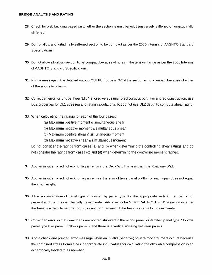
28. Check for web buckling based on whether the section is unstiffened, transversely stiffened or longitudinally
stiffened.
29. Do not allow a longitudinally stiffened section to be compact as per the 2000 Interims of AASHTO Standard
Specifications.
30. Do not allow a built-up section to be compact because of holes in the tension flange as per the 2000 Interims
of AASHTO Standard Specifications.
31. Print a message in the detailed output (OUTPUT code is "A") if the section is not compact because of either
of the above two items.
32. Correct an error for Bridge Type "EIB", shored versus unshored construction. For shored construction, use
DL2 properties for DL1 stresses and rating calculations, but do not use DL2 depth to compute shear rating.
33. When calculating the ratings for each of the four cases:
(a) Maximum positive moment & simultaneous shear
(b) Maximum negative moment & simultaneous shear
(c) Maximum positive shear & simultaneous moment
(d) Maximum negative shear & simultaneous moment
Do not consider the ratings from cases (a) and (b) when determining the controlling shear ratings and do
not consider the ratings from cases (c) and (d) when determining the controlling moment ratings.
34. Add an input error edit check to flag an error if the Deck Width is less than the Roadway Width.
35. Add an input error edit check to flag an error if the sum of truss panel widths for each span does not equal
the span length.
36. Allow a combination of panel type 7 followed by panel type 8 if the appropriate vertical member is not
present and the truss is internally determinate. Add checks for VERTICAL POST = ‘N’ based on whether
the truss is a deck truss or a thru truss and print an error if the truss is internally indeterminate.
37. Correct an error so that dead loads are not redistributed to the wrong panel joints when panel type 7 follows
panel type 8 or panel 8 follows panel 7 and there is a vertical missing between panels.
38. Add a check and print an error message when an invalid (negative) square root argument occurs because
the combined stress formula has inappropriate input values for calculating the allowable compression in an
eccentrically loaded truss member.

BRIDGE ANALYSIS AND RATING
xxix
39. Add a check to allow multiple negative stringer locations when computing main girder effective slab width.
40. Recompile the program using the latest version of Compaq Visual Fortran.
41. Do not check for uplift on stringers of a GFS type bridge.
42. Revise the User's Manual to reflect that output values for the design fatigue stress range (FSRD) and the
effective fatigue stress range (FSRE) do not contain the PA Traffic Factor (PTF).
43. The allowable compression in an eccentrically loaded truss member using the combined stress formula is
based on factor of safety equal to 2.12 for IR and 1.70 for OR. Previously it was based on 0.55 Fy for IR
and 0.75 Fy for OR.
44. Correct shear strength calculation for end panels of transversely stiffened girders. Do not include post-
buckling resistance due to tension-field action (Use AASHTO equation 10-119 instead of AASHTO equation
10-114).
45. Correct shear strength calculation for interior panels of transversely stiffened hybrid girders. Do not include
post-buckling resistance due to tension-field action (Use AASHTO equation 10-149 instead of AASHTO
equation 10-113).
46. Use the Safe Load Capacity (SLC) ratings if they exist for an APRAS/ABAS job.
47. Add a new live load posting vehicle TK527.
48. Add an input error edit check to flag an error if the accumulative sum of truss panel widths does not fall
within 1/2" of the accumulative span lengths for each span.
49. Add an input error edit check to flag an error if the truss "HINGE AT" joint designation on the Bridge Cross
Section and Loading data is not at a support.
50. Provide an error message if a negative stringer location is entered when the OVERHANG is zero.
51. Compute the allowable tension in truss members that have moment of inertia equal to zero and only skip
the calculation of allowable compression.
52. Add an input error message to flag when brace points or stiffeners are entered for a stringer.

BRIDGE ANALYSIS AND RATING
xxx
53. Correct calculations to use appropriate stringer section properties based on stinger span. This is because
the effective slab width may now be different between spans.
54. Add a check for an unexpected end-of-file and print out an informative error message.
55. Change ML80 & TK527 loadings as per PUB 238, page IP 03-2. lso, use this same methodology for special
live loads that have 3% INCR. The axle weights for the ML80 and TK527 loadings shown in Figure 2.4.1
Standard Live Loadings include the 3% scale tolerance allowed by the vehicle code. When calculating the
gross vehicle weight of these vehicles for determining the ratings in tons, the 3% tolerance is removed.
56. Correct the calculation of moment of inertia for a composite section when the neutral axis is above the
bottom of the slab. The area of concrete below the neutral axis should be neglected.
57. For bridge type GGF, correct the calculation of the effective slab width for the critical girder by using the
same method used to calculate the effective slab width for a critical stringer.
58. Correct a problem where erratic results (very large ratings or *****) were being printed for certain special
loads.
59. Correct a problem where Type FSS with floorbeam overhang causes BAR7 to crash or go into a loop.
60. Allow more than 5 spans for a continuous truss. Limit is 15 spans, same as for girders.
61. Add new bridge Type TTT to analyze a truss only with no floorbeams or stringers.
62. Rearrange the output of the input default values into the order in which they are entered.
63. Use 1983 AASHTO 3.23.4.3 to calculate the moment distribution factor for Type CPL instead of 1996
AASHTO 3.23.4.3.
64. Add a Note to the output stating that the program does not check stiffener spacings against the
AASHTO/DM4 minimum stiffener spacing criteria.
65. Use the clear depth instead of the total depth to calculate the area of the web when computing shear
stresses.
66. Add an input check and print an error when stringer/girder locations are unsymmetrical about the center of
floorbeam span.

BRIDGE ANALYSIS AND RATING
xxxi
67. Correct the calculation for the weight of floorbeams that have overhangs. The length of the overhang was
incorrectly included in the length of the first positive range.
68. Allow comment lines to be included in a separate special live load input file.
69. The User's Manual has been revised for the above revisions. In addition, the manual’s format was changed
and the manual is available in Adobe Acrobat PDF format.
The following is a list of reported errors, user requests and clarifications from BAR7 Version 7.9 that have not been
addressed in Version 7.10.
1. Incorporate CBA and BSP libraries to be used as engines in BAR7.
2. Add new input items to make use of BSP library to allow for non-standard beam sections (deteriorated or
patched).
3. Add new input items to make use of CBA library to allow for user supplied or non-uniform dead loads. This
will provide capability to analyze counterweights to prevent uplift as well as point loads.
4. Provide analysis for a special live load in one lane and a specified "other" vehicle(s) in remaining lane(s),
where "other" vehicle(s) are defined through the LIVE LOAD field on the Project Identification.
5. Add two new codes to the LIVE LOAD field on the Project Identification as follows: I - consider HS20 and
ML80 loadings and J - consider HS25, IML and ML80 loadings.
6. Add new input items for single lane distribution factor and multi-lane distribution factors, moment and shear.
7. Add a third option to LANES input for user to define a median barrier.
8. Allow different gage distances for multiple special live loads and recalculate distribution factors for each
load.
9. Check provisions of AASHTO Equation (10-119) when rating unsymmetrical stiffened girders.
10. Correct calculation of estimated fatigue life HS20 TRK STRESS for positive and negative live load plus
impact moments. The program should use the distribution factor for one lane instead of the multi-lane
moment distribution factor entered by the user.

BRIDGE ANALYSIS AND RATING
xxxii
11. Provide the capability to handle the situation where the deck is overhanging the girder with no cantilever or
bracket on the floorbeam.
12. Allow a cantilever floorbeam to be non-continuous, i.e., partial or no moment passed thru at the support.
13. Incorporate new equation for Cb (AASHTO 10.48.4.1) for discreetly supported compression flange of a
floorbeam, stringer or girder.

BRIDGE ANALYSIS AND RATING
xxxiii
SUMMARY OF OCTOBER 2003 REVISIONS - VERSION 7.10a
BAR7 Version 7.10a contains the following revisions.
1. Correct an input error that was inadvertently being printed for some truss bridges. When checking for the
“HINGE AT” location not falling on a support, in some instances, the program was printing the error even
though the hinge was on a support.
2. Correct an error in the compactness check for a positive moment composite section. The program was
causing compact sections to be treated as non-compact because the b’/t ratio was greater than the
maximum b’/t for a non-composite section.
3. When analyzing a section that falls at a brace point, clarify the unbraced section maximum strength for
output option “A” by printing brace points x1 and x2.

BRIDGE ANALYSIS AND RATING
xxxiv
SUMMARY OF MARCH 2004 REVISIONS - VERSION 7.11
BAR7 Version 7.11 contains the following revisions.
1. Incorporate the Department’s Continuous Beam Analysis (CBA) program as a library and use it as an
analysis engine for BAR7. This yields slightly different but more accurate results of BAR7 because:
• CBA uses centroid instead of midpoint of M/EI trapezoidal loading.
• CBA uses 20th points instead of 10th points for an analysis of a girder.
• CBA uses a couple of new load positions for the vehicle placement over the influence line.
2. Incorporate the Department’s Beam Section Properties (BSP) program as a library so that sections
properties calculated and used in BAR7 are consistent with other programs.
3. Incorporate the following corrections that were included in BAR7 v7.10a:
• Correction to the input edit check for the HINGE AT location that is not on a support.
• Correction for error with the rating of positive moment composite sections such that b’/t limit is not
used.
• Eliminate the NaN error for some truss member forces.
4. Use Compaq Visual Fortran to break the source code into separate files for each routine and code all
COMMON blocks into INCLUSE statements (this does not affect the BAR7 results).
Note: The reported errors, user requests and clarifications except for item1 listed on page xxx have not yet been
addressed in Version 7.11. They will be addressed in future versions of BAR7.

BRIDGE ANALYSIS AND RATING
xxxv
SUMMARY OF DECEMBER 2004 REVISIONS - VERSION 7.11.0.6
BAR7 Version 7.11.0.6 contains the following revisions.
1. Add a warning message to clarify the situation where the user enters a shear distribution factor and
designates that there is only one stringer and it is an interior stringer. The program will use the inputted
value instead of the value calculated based on the interior stringer's spacing. (BAR7REV116)
2. Correct a problem where a Type GFS structure with no slab and very small stringers plus multiple stringer
spans and multiple live loads caused an abnormal termination. (BAR7REV117)
3. Clarified the descriptions of the DL1 and DL2 input items in the User’s Manual pertaining to their use in the
application of sidewalk live load. (BAR7REV118)
4. Add two new codes for the LIVE LOAD input item on the PROJECT IDENTIFICATION data. Use code “I”
to consider HS20 and ML80 loadings. Use code “J” to consider HS25, IML and ML80 loadings.
(BAR7REV055)
5. Correct the User’s Manual on page 1-2. Define AASHTO Specifications as AASHTO Standard
Specifications for Highway Bridges, Fifteenth Edition, 1996. (BAR7REV120)
6. Correct a problem where a Type GFF structure with more than fourteen floorbeams caused an abnormal
termination. (BAR7REV121)
7. Increase the size limit for the length of file names so that extra long file names (more than 100 characters)
may be used. (BAR7REV122)
8. Correct an error in the calculation of the load factor rating based on concrete strength in a composite
section. The program now computes the stress due to DL2 using the modular ratio of 3n. Previously it was
incorrectly using the modular ratio of n. (BAR7REV123)
9. Apply one-lane distribution factor instead of multi-lane distribution factor to the HS20 TRK STRESS +(LL+I)
and -(LL+I) values printed in the FATIGUE LIFE ESTIMATION output. (BAR7REV060)
10. On the Girder Fatigue Detail input, add fatigue detail categories BP and EP, equivalent to B' and E', to work
around an issue with Engineering Dataset Manager. (BAR7REV124)
11. Correct a problem where the program printed asterisks in some of the Fatigue Analysis output fields when
running with Output Option 6. (BAR7REV126)

BRIDGE ANALYSIS AND RATING
xxxvi
12. When calculating the live load factors for a floorbeam, neglect the wheel loads that do not fall within the
limits of the length of the floorbeam. (BAR7REV127)
13. Add a new input item (END PANEL) to the Project Identification to act as a switch to disallow the shear in
the end panel from governing the rating at that section. BAR7 version 7.9 and earlier erroneously allowed
the shear capacity to include post buckling strength in the end panel of girders. This was also true for the
interior and end panels of hybrid girders. BAR7 version 7.10 corrected this problem, however, the load
rating for some girder structures are now controlled by low shear ratings in the end panel. (BAR7REV128)
14. Add an input error message when a brace point spacing is entered greater than the span length.
(BAR7REV129)
BRIDGE ANALYSIS AND RATING
xxxvii
SUMMARY OF JULY 2005 REVISIONS - VERSION 7.11.0.8
BAR7 Version 7.11.0.8 contains the following revisions.
1. A problem has been corrected where a truss analyzed for a uniform lane load entered via the Special Live
Load input gives the same incorrect result for LL forces regardless of the value entered for the Uniform
Lane Load. (BAR7REV131)
2. The revision to BAR7 v7.10 (BAR7REV047) required the use of AASHTO 10.48.8.3 Equation (10-149)
when calculating the allowable shear force for hybrid girders. This was causing unusually low ratings for
some existing structures. A new input item (HYB) has been added to act as a switch. The purpose of this
new input switch will be to select the shear rating equation to use for hybrid sections, AASHTO 10.48.8.3
equation (10-149) or equation (10-113). (BAR7REV132)
3. The revision to BAR7 v7.11.0.6 (BAR7REV128) did not change the calculation of the allowable shear force
in an end panel. It simply provided a switch to disallow end panel shear governing. This sometimes resulted
in a rating of 999.99 reported at that section. Instead of using the new END PANEL input switch to override
the end panel shear rating, the switch is now used to determine whether to use AASHTO Equation (10-
118) or (10-113). (BAR7REV133)
4. For a continuous composite girder, the program attempts to compute a negative moment rating based on
the amount of reinforcement in the slab. When zero area of steel is entered for the longitudinal slab
reinforcement, the program abnormally terminated with a divide by zero. A check has been added to print
an input error when no longitudinal slab reinforcement is entered for a continuous composite girder.
(BAR7REV134)
5. Figure 2.4.1 Standard Live Loadings has been revised to reflect the more accurate value of 13.68 kips for
the first axle of the ML80 live load. (BAR7REV135)

BRIDGE ANALYSIS AND RATING
xxxviii
SUMMARY OF DECEMBER 2005 REVISIONS - VERSION 7.11.0.9
BAR7 Version 7.11.0.9 contains the following revisions.
1. The limit for the maximum number of axles for user defined Special Live Loads has been increased from
24 to 80. (BAR7REV136)
2. A problem has been corrected for a truss analysis job that abnormally terminated when the panel type
configuration produced zero force in one of the top chords. An input error message is now generated when
an invalid panel type configuration is encountered. (BAR7REV137)
3. A problem was corrected where a job would abnormally terminate when run through the Engineering
Manager or Engineering Assistant graphical user interface (GUI). The program will now run and produce
the appropriate messages in the output listing that is accessible in the GUI. (BAR7REV138)
4. At a girder section where lane loading governs for an H20 Truck, it was detected that the Critical Rating
was greater than the POS MOM Rating on the Load Rating summary page. This problem is related to
revision number 33 in the Summary of April 2003 Revisions - Version 7.10 on page xxvii. The program has
been modified so that when determining the minimum positive and negative moment ratings, the cases for
maximum positive shear & simultaneous moment and maximum negative shear & simultaneous moment
are not considered. (BAR7REV139)

BRIDGE ANALYSIS AND RATING
xxxix
SUMMARY OF MAY 2007 REVISIONS - VERSION 7.12.0.0
Since the release of BAR7 Version 7.11.0.9, several error reports and user requested enhancements have been
received. This release of BAR7 Version 7.12.0.0 contains the following revisions.
Input Revisions
1. A cross check error was fixed in the program when the maximum number (i.e. 5) of different Floorbeam
brace point spacings or stiffener spacings was entered. (BAR7REV141)
2. A problem has been corrected where the input variables for the FY in the top and bottom flanges of a
stringer were not being used properly. (BAR7REV146)
3. An input check was added and an error message is printed if more than 3 floorbeams are entered.
(BAR7REV152)
Output Revisions
4. When running a job with additional section properties analysis points added, the output is reporting this
point twice in the tables of section properties. Added a check for duplicate analysis points and skipped
printing those points. (BAR7REV154)
5. Modified the program to print code 1 for negative moment impact factor at a point with negative moment.
(BAR7REV155)
6. Corrected the discrepancy in the printing of the message “NOTE: THIS MEMBER DOES NOT HAVE ALL
SECTIONS QUALIFIED AS COMPACT SECTIONS. THEREFORE, EVEN …” between simple spans or a
continuous span. (BAR7REV158)
7. Corrected the value being reported for the MR at that section when reviewing the detailed output for a
specific section of a continuous girder. (BAR7REV156)

BRIDGE ANALYSIS AND RATING
xl
Section Property Revisions
8. A problem has been corrected where the program was reporting invalid section properties at all but the first
location when analyzing stringers at multiple locations. (BAR7REV145)
9. Corrected the bottom flange angle vertical and horizontal leg dimensions in the sketch for the built-up
section in the EngAsst. Previously, this sketch for built-up section was not consistent with the sketch on
Page 5-55 in the User’s Manual. (BAR7REV144)
10. The program has been enhanced to compute section properties on both sides of the cutoff for the purpose
of analyzing and rating each section. Previously, BAR7 picked the section properties that had the less
moment capacity and used those properties for the rating calculations. Please note that for the purpose of
stiffness and determining the reactions, moments, shears, deflections, and rotations, the BAR7 process
does not change and it will pass the appropriate moment of inertia to CBA. (BAR7REV150)
11. A problem has been corrected because the depth of section was not calculated correctly when a variable
depth plate girder section (Type P) transitions into a wide flange beam (Type W). Modified the code to
accommodate all combinations of steel member types and variable depths. (BAR7REV159)
Live Load Revision
12. A problem has been corrected where the program was reporting invalid section properties at all but the first
location when analyzing stringers at multiple locations. (BAR7REV145)
13. The Live Load code of “9” should not be a valid code according to the documentation. In case there may
be some old input files with live load code equal to “9”, the “9” will be interpreted as number of special live
loads equal to one. (BAR7REV149)
Flexural Capacity Revision
14. The program has been enhanced to calculate correctly the moment capacity of a reinforced concrete T-
beam when the area of compression reinforcement is equal to (or close to equal to) the area of tension
reinforcement in the beam. (BAR7REV151)
15. Modified the program to use M1/M2 ratio based on the span 2 unbraced length when analyzing the point
at the end of the span 2 and to use M1/M2 ratio based on the span 3 unbraced length when analyzing the
point at the beginning of the span 3. (BAR7REV153)
16. Corrected the signs of the MU values at some of the brace points. (BAR7REV157)

BRIDGE ANALYSIS AND RATING
xli
Program Revision
17. The program has been converted to Intel Visual Fortran compiler v9.1. (BAR7REV140)

BRIDGE ANALYSIS AND RATING
xlii
SUMMARY OF MAY 2008 REVISIONS - VERSION 7.12.0.1 BAR7 Version 7.12.0.1 contains the following revisions: General Program Revisions
1. Corrected a problem where all the sections properties at the beginning of the first span were equal to zero.
This was causing slight differences in the results for continuous span structures.
2. Resolved conflicting variable name and subroutine name issue between BAR7 and CBA code.
(BAR7REV162)
3. Allowed for a CBA enhancement that accepts user defined distribution factors. (BAR7REV163)
Input Revisions
4. When a negative cover plate thickness is entered for a wide flange section to describe a deteriorated flange,
the program now assumes the deterioration applies the entire flange width when the corresponding cover
plate width is not entered (left blank). Previously, the program would only consider the deterioration when
a value was entered for the corresponding cover plate width. (BAR7REV164)
5. Live load codes 7 and 8 were added to the dropdown list for the “Live Load” field of the “Project” tab in
Engineering Assistant (EngAsst). (BAR7REV166)
Output Revisions
6. The unbraced length (Lb) and width of the projecting flange element (b′) values are now printed in the
detailed output when the 1989 AASHTO Specification is used to compute the maximum strength of an
unbraced section. (BAR7REV161)
Load Revisions
7. Added a separate live load (beta) factor of 1.0 for the P-82 permit vehicle. (BAR7REV160)
User Manual Revisions
8. Corrected the shear capacity equation for Operating Ratings for slab bridges and T-beam bridges in Section
3.6.3 of the User’s Manual. (BAR7REV165).

BRIDGE ANALYSIS AND RATING
xliii
SUMMARY OF APRIL 2010 REVISIONS - VERSION 7.13.0.0
Since the release of BAR7 Version 7.12.0.1, several error reports and user requested enhancements have been
received. This release of BAR7 Version 7.13.0.0 contains the following revisions.
General Program Revisions
1. Revise the Truss Geometry Images 2 and 3 in the Engineering Assistant (EngAsst) and Figure 5.11.1
(Truss Geometry) in the User Manual to clarify the meaning of H3 parameter. Add Figure 5.11.6 Truss
Geometry (Example 4) to better explain the input of Truss Geometry. (BAR7REV169)
2. Correct a typo of Live Load item in the Help Screen of project tab in EngAsst. (BAR7REV176)
3. Revise the Chapter 7 Example 5 pp 7-42 & 7-53. In example 5, the Lane, Moment Distribution Factor, and
Ranges of Steel Member Property card are incorrect. Also, change text to improve readability.
(BAR7REV180)
Input Revisions
4. Correct the end-of-file error for bridge type of “TTT” when the input data file does not have a blank input
line at the end of input file. (BAR7REV168)
5. Add the edit check for special live loads: you must have the truck load and the number of axles of this
truck shall be between 2 and 80. (BAR7REV171)
6. Increase the number of ranges in the Steel Member Properties card to 100. (BAR7REV172)
7. Correct a typo in format (XXXDD) of the WF BEAM OR WEB PLATE DEPTH of Steel Member Properties
card in Figure 5.1.6 (Input Form 6) of the User Manual. (BAR7REV178)
8. Add GUSSET PLATE PROPERTIES card and GUSSET PLATE MEMBERS card to allow the user input
the gusset plate information. (BAR7REV167)
9. Correct an incorrect error check for the Distribution Factors with a “TTT” bridge type. Distribution factors
don’t need to be entered for the bridge type of “TTT”. (BAR7REV181)
10. Add the edit check for ADTT Year to avoid the "Divide by Zero" error which crashed the program.
(BAR7REV182)
BRIDGE ANALYSIS AND RATING
xliv
Section Property
11. Implement unreleased version of Beam Section Property (BSP) v1.5.0.2. The current release version of
BSP is v1.3. (BAR7REV173)
12. For Steel Member Properties card, increase the lines of steel members to 300 (150 if SYMMETRY is
entered “Y”). (BAR7REV179)
13. Output the program calculated truss member lengths so that users can verify that the truss model is
correct. (BAR7REV170)
Allowable Stress
14. The allowable bending stress equation as listed in Tables 6.6.2.1-1 and 6.6.2.1-2 of the 1994, 2nd Edition
(2000 Interim) AASHTO Manual for the Condition Evaluation of Bridges shall be used when checking the
combined stress equation in AASHTO 10.36. Several new Items were added into Truss Member Properties
card in Figure 5.1.5 (Input Form 5). This option is available when CORS in the Bridge Cross Section and
Loading card is coded with “X”. (BAR7REV174)
Load Revisions
15. Add the skew correction factor for shear to account for increased shear due to skew as refer to the
AASHTO LRFD Section 4.6.2.2.3c for bridge types of “CTB” and “GGG”. The skew correction item was
added into Bridge Cross Section and Loading card in Figure 5.1.1 (Input Form 1) of the User Manual.
(BAR7REV175)
Gusset Plate
16. The program has been revised adding the ability of gusset plate analysis and rating utilizing Load Factor
Rating (LFR) method. (BAR7REV167)
Program Revision
17. The program has been converted to Intel Visual Fortran compiler 10.1.013 using Microsoft Visual Studio
2005. (BAR7REV177)

BRIDGE ANALYSIS AND RATING
xlv
SUMMARY OF AUGUST 2013 REVISIONS - VERSION 7.13.0.1
Since the release of BAR7 Version 7.13.0.0, several error reports and user requested enhancements have been
received. This release of BAR7 Version 7.13.0.1 contains the following revisions.
General Program Revisions
1. Add two values to the SLC Level field at the PROJECT IDENTIFICATION card. If the SLC level is
expresses as a percent of Operating Rating Factor, enter the letter “A” followed by a two-digit number
which indicate the percent of Operating Rating Factor that can be used in determining the Safe Load
Capacity of the bridge. (BAR7REV197)
Program Revision
2. This program has been converted to Intel(R) Visual Fortran Compiler XE on IA-32, version 12.1.3
Package ID: w_fcompxe_2011.9.300 with Microsoft Visual Studio 2010. (BAR7REV198)

BRIDGE ANALYSIS AND RATING
xlvi
SUMMARY OF OCTOBER 2014 REVISIONS - VERSION 7.14.0.0
Since the release of BAR7 Version 7.13.0.1, several error reports and user requested enhancements have been
received. This release of BAR7 Version 7.14.0.0 contains the following revisions.
Programming Revisions
1. The method of calling the engineering program DLL from the Engineering Assistant has been changed for
compatibility with EngAsst v2.5.0.0 which uses Microsoft’s .NET Framework, version 4.5. Because of
this, BAR7 will no longer work with EngAsst v2.4.0.6 or v2.4.0.9 unless the EngAsst “Edit / Run EXE -
Command Window” option is selected. BAR7 will no longer work with EngAsst v2.4.0.0 and earlier.
2. The program has been compiled with Intel Visual Fortran compiler XE 12.1.3.300 [IA-32] using Microsoft
Visual Studio 2010 version 10.0.40219.1. (BAR7REV201)
Input Revisions
3. Various new input items were added.
PONY TRUSS field at the PROJECT IDENTIFICATION card
PDF field at the PROJECT IDENTIFICATION card
PATCH Field at the BRIDGE CROSS SECTION AND LOADING card
Various fields at the ADDITIONAL TRUSS MEMBER PROPERTIES card
Various fields at the CONCENTRATED PATCH LOADS card
Various fields at the DISTRIBUTED PATCH LOADS card
4. Added an edit check to prevent users from entering 0 for span no in STEEL MEMBER PROPERTIES
CARD. (BAR7REV189)
5. Added edit checks to prevent BAR7 from crashing unexpectedly if "L" is entered for LANES and the
bridge type is "FSS", "GFF", "GFS", "GGF", "TFF", "TFS", or “TTT”. For one loaded traffic lane if the
traffic lane width (WIDTH) is greater than zero, then the percentage of the live load to be applied to the
traffic lane, %LL, shall not be zero. Otherwise, the program crashes due to division by zero. For multiple
loaded traffic lanes, the WIDTH and %LL of at least one loaded lane shall not be zero. It is possible that
some lanes can have %LL = 0%. (BAR7REV190)
Load Rating Revisions
6. For the Load Factor method, the program now assumes the contribution of the bent up bars to the shear
capacity (entered as shear area, Av, for R.C. slabs (Bridge Type = CSL)) applies only up to a distance
based on d distance and ALPHA. (BAR7REV183)
7. Load Factor ratings are now provided for truss members with or without eccentricity. (BAR7REV191)

BRIDGE ANALYSIS AND RATING
xlvii
Load Revisions
8. Provided options to place uniform and/or concentrated loading on a bridge. The effects of these patch
loads are considered as dead loads and are added into dead load effects for load rating analyses.
(BAR7REV192)
9. Corrected an error that caused the program to abort when 6 Special Live Loads were entered. The
number of special live loads was increased to 8. (BAR7REV185)
10. For the LIVE LOAD field of PROJECT IDENTIFICATION card, a new loading code, K, was added to
automatically evaluate the HS, ML-80, TK527, PA58, and AASHTO Type 3 loadings. (BAR7REV199)
Output Revisions
11. For concrete bridges, the output format of the live load analysis results was revised. (BAR7REV184)
12. Corrected the member length calculation for the end post of Panel 0. The member length was reported in
feet instead of inches. (BARREV187)
13. The PDF output file creation is now optional. (BAR7REV196)
Specification Revisions
14. Incorporated a top chord stability check for top chords and vertical chords at up to three floorbeam
locations for pony trusses. (BAR7REV194)

BRIDGE ANALYSIS AND RATING
xlviii
SUMMARY OF JANUARY 2015 REVISIONS - VERSION 7.14.0.1
Since the release of BAR7 Version 7.14.0.0, several problem reports have been received. This release of BAR7
Version 7.14.0.1 contains the following revisions.
Programming Revisions
1. The member IDs and member forces reported for each plate location in the "Gusset Plates: DL & LL Forces
and Angles" tables for truss panels with midpoints may be incorrectly matched. However, the correct
member forces are used for the rating calculations. The output table has been corrected. (BAR7REV202)
2. For patch load analysis of girders, an incorrect array index for the end shears may result in an array bound
error. The array index was corrected. (BAR7REV203)
3. Flange projection violations (888.88 F) in the detailed “Strength and Load Factor Ratings” tables were
mistakenly not reported while a warning was displayed following the rating summary table at the end of the
output file. The projection violations are now reported in the “Strength and Load Factor Ratings” tables.
(BAR7REV204)

BRIDGE ANALYSIS AND RATING
xlix
SUMMARY OF JUNE 2017 REVISIONS - VERSION 7.14.0.3
Since the release of BAR7 Version 7.14.0.1, several error reports and user requested enhancements have been
received. This release of BAR7 Version 7.14.0.3 contains the following revisions.
Load Revisions
1. Added a new live load code, L, at the PROJECTION IDENTIFICATION data card to automatically
evaluate the load ratings of EV2, EV3, and SU6TV loadings per the FHWA load rating for FAST Act’s
emergency vehicles memo dated November 3, 2016 (BAR7REV215).
EV2: single rear axle emergency vehicle
Two axles: 24k – 15’ – 33.5k
EV3: tandem rear axle emergency vehicle
Three axles: 24k – 15’ – 31k – 4’ – 31k
SU6TV: heavy-duty tow and recovery vehicle
11 axles: 5.75k – 10’ - 8k – 4’ - 8k – 4’ – 25.63k – 4’ – 25.63k – 4’ - 8k –
14’ – 8k – 4’ - 8k – 4’ - 17k – 4’ - 17k – 4’ - 8k
2. Added AASHTO Type 3-S2 and AASHTO Type 3-3 to the existing LIVE LOAD code, K, at the
PROJECTION IDENTIFICATION data card (BAR7REV220)

BRIDGE ANALYSIS AND RATING
l
SUMMARY OF FEBRUARY 2018 REVISIONS - VERSION 7.15.0.0
Since the release of BAR7 Version 7.14.0.3, several error reports and user requested enhancements have been received. This release of BAR7 Version 7.15.0.0 contains the following revisions.
General Program Revisions
1. For bridge types of "FSS" & "GGF", the UNSYM PIER field at the column of 79 of the BRIDGECROSS SECTION AND LOADING card was added to allow the user whether to implement onefloorbeam analysis under unsymmetrical pier support configuration per BAR7 Run(BAR7REV193).
2. Increase the maximum number of FBs to be analyzed to 5 (from 3) and increase the maximumnumber of FB ranges to 9 (from 5) for symmetrical FB and to 18 (from 5) for unsymmetrical FB(BAR7REV209).
3. Increase user-input traffic lane locations from 6 to 7 in Traffic Lane Location data card and addedan error message of "total lane width (xxxx.xx) in the Traffic Lane Locations card input shall beless than the roadway width (xxxx.xx) (BAR7REV211).
4. Added the warning message in subroutine XL_Brace.for 1. when PR10 is true (OUTPUT = A) andthere is a governing positive moment and the top flange if not braced; 2. when PR10 is true andthere is a governing negative moment and the bottom flange is not braced (BAR7REV213).
5. Corrected the mistake of the deck contribution areas for end exterior floorbeam when calculatingthe dead load reactions from the single-span stringer above acting to the floorbeams(BAR7REV218).
6. Added new rating factor codes to indicate whether the flange or web buckling controls in the finalratings in the Rating Summary (BAR7REV219).
7. This program has been converted to Microsoft Visual Studio Professional 2017 version 15.4.4 andIntel(R) Visual Fortran Compiler (2017 update 5) version 17.0.5.267 (IA-32) (BAR7REV221)
Input Revisions
8. Various new input items were addedCOMPACT field at the PROJECTION IDENTIFICATION cardUNSYM PIER field at the BRIDGE CROSS SECTION AND LOADING cardUPC card = UNSYMMETRICAL PIER SUPPORT CONFIGURATION cardLANE 7 at the TRAFFIC LANE LOCATIONS cardSECTION SHAPE field at the STEEL MEMBER PROPERTIES card
BRIDGE ANALYSIS AND RATING
li
Load Factor
9. For load factor method, add an input item, COMPACT, at the column 79 of the PROJECTIDENTIFICATION card to allow the user whether to implement the all-or-none compactrequirements in the calculation of rating summary for stringers, floorbeams, and girders(BAR7REV206).
Load Revisions
10. For bridge type of “GGF” which has multiple beams (or stringers) supported by the floorbeamsbelow, user shall use DL1 for stringer analysis using the girder subroutine and DL1ST was notused. DL1ST shall be used in the floorbeam analysis (the computation of DL1 concentrated deadload reactions acting on the floorbeams from stringers above) using the floorbeam subroutine.Therefore, for floorbeam analysis, if DL1ST was not entered by the user, DL1ST will be restored bythe value of DL1 entered by the user (BAR7REV207).
11. Provide options to place uniform and/or concentrated patch loading on floorbeams of a bridge(BRA7REV208).
12. For steel members composited with the reinforced or non-reinforced concrete deck, the CONCDECK in the PROJECT IDENTIFICATION card shall be entered with a “Y” and the CONCRETEMEMBER PROPERTIES card shall be entered. If not, a warning message will be issued instead ofissuing the error message to stop the BAR7 program because the previous existing incorrectcode in APRAS. The integral wearing surface (default is 0.5”) entered by the user shall bededucted from the SLAB THICK in the BRIDGE CROSS SECTION AND LOADING card for thecalculation of the section properties (BAR7REV210).
Box-shape Floorbeam
13. For bridge type of “FSS” or “GGF”, rating of non-composite, non-compact box-shape crossgirders workaround using BAR7 program with I-shape beams with minor modifications on input.(BAR7REV216)
Output
14. For Output Option = 6 (fatigue estimation only) and PDF = Y, the result shall produce the pdfoutput (BAR7REV205).
15. Instead of printing the special live output based on the sequence of input in the data file,program shall print the special live output based on their Special Live Load IDs(BAR7REV212).

BRIDGE ANALYSIS AND RATING
lii
This page is intentionally left blank.
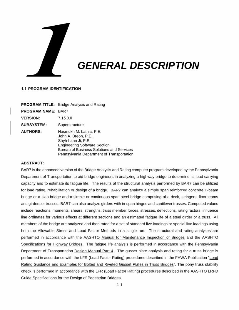
1-1
GENERAL DESCRIPTION
PROGRAM IDENTIFICATION
PROGRAM TITLE: Bridge Analysis and Rating
PROGRAM NAME: BAR7
VERSION: 7.15.0.0
SUBSYSTEM: Superstructure
AUTHORS: Hasmukh M. Lathia, P.E. John A. Breon, P.E. Shyh-hann Ji, P.E. Engineering Software Section Bureau of Business Solutions and Services Pennsylvania Department of Transportation
ABSTRACT:
BAR7 is the enhanced version of the Bridge Analysis and Rating computer program developed by the Pennsylvania
Department of Transportation to aid bridge engineers in analyzing a highway bridge to determine its load carrying
capacity and to estimate its fatigue life. The results of the structural analysis performed by BAR7 can be utilized
for load rating, rehabilitation or design of a bridge. BAR7 can analyze a simple span reinforced concrete T-beam
bridge or a slab bridge and a simple or continuous span steel bridge comprising of a deck, stringers, floorbeams
and girders or trusses. BAR7 can also analyze girders with in-span hinges and cantilever trusses. Computed values
include reactions, moments, shears, strengths, truss member forces, stresses, deflections, rating factors, influence
line ordinates for various effects at different sections and an estimated fatigue life of a steel girder or a truss. All
members of the bridge are analyzed and then rated for a set of standard live loadings or special live loadings using
both the Allowable Stress and Load Factor Methods in a single run. The structural and rating analyses are
performed in accordance with the AASHTO Manual for Maintenance Inspection of Bridges and the AASHTO
Specifications for Highway Bridges. The fatigue life analysis is performed in accordance with the Pennsylvania
Department of Transportation Design Manual Part 4. The gusset plate analysis and rating for a truss bridge is
performed in accordance with the LFR (Load Factor Rating) procedures described in the FHWA Publication ”Load
Rating Guidance and Examples for Bolted and Riveted Gusset Plates in Truss Bridges”. The pony truss stability
check is performed in accordance with the LFR (Load Factor Rating) procedures described in the AASHTO LRFD
Guide Specifications for the Design of Pedestrian Bridges.

Chapter 1 Program Identification
1-2
ABBREVIATIONS
This section provides definitions of abbreviations that are commonly used throughout this User’s Manual.
AASHTO - American Association of State Highway and Transportation Officials.
AASHTO Specifications - AASHTO Standard Specifications for Highway Bridges, Fifteenth Edition, 1996.
This publication can be ordered from:
American Association of State Highway and Transportation Officials
444 North Capitol Street, N.W., Suite 249
Washington, D.C. 20001
AASHTO Manual - AASHTO Manual for Condition Evaluation of Bridges, Second Edition, 1994 as revised
by the 1995, 1996, 1998 and 2000 Interim Revisions. This publication can be ordered
from:
American Association of State Highway and Transportation Officials
444 North Capitol Street, N.W., Suite 249
Washington, D.C. 20001
AASHTO Guide Spec for Pedestrian Bridges
AASHTO LRFD Guide Specifications for the Design of Pedestrian Bridges, December
2009
AASHTO Guide Spec for Truss
AASHTO Guide Specifications for Strength Design of Truss bridges (Load Factor
Design) 1985
BD Standards - Standards for Bridge Design, Prestressed Concrete, Reinforced Concrete and
Steel Structures, January 1989 Edition, Pennsylvania Department of Transportation.
DM-4 - Pennsylvania Department of Transportation Design Manual Part 4, August 1993
Edition. This publication can be ordered from:
Pennsylvania Department of Transportation
Publication Sales, P.O. Box 2028
Harrisburg, PA 17105
FHWA - Federal Highway Administration
PennDOT - Pennsylvania Department of Transportation.

2-1
PROGRAM DESCRIPTION
GENERAL
Rating a bridge for its capacity to carry the live load safely and to provide a useful service requires a careful
evaluation of many complex factors. This evaluation must include a complete detailed analysis of the structure using
some established standard. The objective of this program is to aid the bridge engineer in performing the analysis
required to determine the live load capacity rating and the fatigue life of a bridge using the standards provided by
the AASHTO Manual for Maintenance Inspection of Bridges, the 1996 AASHTO Specifications for Highway Bridges,
and the Pennsylvania Department of Transportation Design Manual Part 4.
For this manual, the AASHTO Manual for Maintenance Inspection of Bridges will be referred to as AASHTO Manual,
the 1996 AASHTO Specifications for Highway Bridges will be referred to as AASHTO Specifications, and the
Pennsylvania Department of Transportation Design Manual Part 4 will be referred to as DM4. For further information
about bridge rating, refer to these publications.
The rating of a bridge is determined using a group of specified loads and a predetermined stress level to which the
structure may be subjected to, considering the specified traffic condition. The two stress levels used for this purpose
are called the Inventory stress and the Operating stress. The Inventory stress is the lower stress level to which the
structure may be subjected to for an indefinite period. The Operating stress is the upper stress level and it is the
absolute maximum stress allowed on the structure.
The traffic conditions used for this analysis are the number of design traffic lanes the bridge can carry in accordance
with the AASHTO Manual and the number of traffic lanes that are in service or to be loaded. The ratings are
computed in accordance with the requirements of the AASHTO Manual and the criteria established by the
Pennsylvania Department of Transportation.
The ratings are computed based on flexural stresses for a beam type member (such as a girder, stringer, floorbeam,
concrete slab, or concrete T-beam) and based on axial stresses or combined axial and bending stresses for a truss
member. Both the Allowable Stress Method and the Load Factor Method are used to compute the ratings
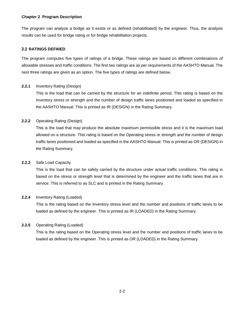
Chapter 2 Program Description
2-2
The program can analyze a bridge as it exists or as defined (rehabilitated) by the engineer. Thus, the analysis
results can be used for bridge rating or for bridge rehabilitation projects.
RATINGS DEFINED
The program computes five types of ratings of a bridge. These ratings are based on different combinations of
allowable stresses and traffic conditions. The first two ratings are as per requirements of the AASHTO Manual. The
next three ratings are given as an option. The five types of ratings are defined below.
2.2.1 Inventory Rating (Design)
This is the load that can be carried by the structure for an indefinite period. This rating is based on the
Inventory stress or strength and the number of design traffic lanes positioned and loaded as specified in
the AASHTO Manual. This is printed as IR (DESIGN) in the Rating Summary.
2.2.2 Operating Rating (Design)
This is the load that may produce the absolute maximum permissible stress and it is the maximum load
allowed on a structure. This rating is based on the Operating stress or strength and the number of design
traffic lanes positioned and loaded as specified in the AASHTO Manual. This is printed as OR (DESIGN) in
the Rating Summary.
2.2.3 Safe Load Capacity
This is the load that can be safely carried by the structure under actual traffic conditions. This rating is
based on the stress or strength level that is determined by the engineer and the traffic lanes that are in
service. This is referred to as SLC and is printed in the Rating Summary.
2.2.4 Inventory Rating (Loaded)
This is the rating based on the Inventory stress level and the number and positions of traffic lanes to be
loaded as defined by the engineer. This is printed as IR (LOADED) in the Rating Summary.
2.2.5 Operating Rating (Loaded)
This is the rating based on the Operating stress level and the number and positions of traffic lanes to be
loaded as defined by the engineer. This is printed as OR (LOADED) in the Rating Summary.

Chapter 2 Program Description
2-3
BRIDGE TYPES
The ratings defined above can be obtained for the following types of bridges. For this program, each bridge type is
designated by a three-character code (given in parenthesis below). This manual will refer to each bridge type by
this code. The types of bridges that can be analyzed and rated using this program are:
1. Single span Precast Concrete Slab Bridge (CPL). See Figure 2.3.1 on page 2-5.
2. Single span Concrete Slab Bridge (CSL). See Figure 2.3.1 on page 2-5.
3. Single span Concrete T-beam Bridge (CTB). See Figure 2.3.1 on page 2-5.
4. Encased I Beam (EIB). In this type of bridge, the steel I section beam is completely or partially encased in
the concrete deck. The beams encased in concrete are either shored or unshored during construction. The
program assumes an encased I-beam as a composite section neglecting concrete below the neutral axis
of the composite section. The encased I-beam can be considered composite only if there is sufficient
reinforcement wrapped around the beam to provide composite action between the beam and slab concrete.
See Figure 2.3.3 on page 2-7.
5. Floorbeam-Stringer Type Bridge (FSS). In this type of bridge, the deck is supported by the floorbeams and
the stringers, and the floorbeam is supported by two columns. The limitations on the floorbeam and stringer
are the same as for the bridge type "GFS" or "TFS", and the floorbeam may not be supported by more than
two columns. Box-shaped steel cross girder/floorbeam are considered as non-composite, non-compact
only. See Figure 2.3.5 on page 2-9.
6. Girder-Floorbeam Type Bridge (GFF). In this type of bridge, the deck is supported by the floorbeams and
there are no stringers. The limitations on the girder and floorbeam are the same as for the bridge type
"GFS". See Figure 2.3.2 on page 2-6.
7. Girder-Floorbeam-Stringer Type Bridge (GFS). In this type of bridge, the main girder and stringer may have
a maximum of fifteen simple or continuous spans. Except for box-shaped steel cross girder/floorbeam, the
main girder and floorbeam may be composite or non-composite with variable or uniform cross section. The
stringer must have a uniform cross section. See Figure 2.3.2 on page 2-6.
8. Multigirder-Floorbeam Type Bridge (GGF). In this type of bridge, the deck is supported by beams or girders
that span over floorbeams. The floorbeam is supported by two columns. The limitations on the girder are
the same as for the bridge type "GGG", and the floorbeam may not be supported by more than two columns.
Box-shaped steel cross girder/floorbeam are considered as non-composite, non-compact only. See Figure
2.3.5 on page 2-9.
9. Multigirder Steel Bridge (GGG) with a maximum of fifteen simple or continuous spans and either composite
or non-composite cross-section. See Figure 2.3.1 on page 2-5.
10. Truss-Floorbeam Type Bridge (TFF). In this type of bridge, the deck is supported by the floorbeams and
there are no stringers. The limitations on the truss are the same as for the bridge type "TFS". The limitations
on the floorbeam are the same as for the bridge type "GFS". See Figure 2.3.4 on page 2-8.
11. Truss-Floorbeam-Stringer Type Bridge (TFS). A single span truss or a continuous truss with two to fifteen
spans may be analyzed. The total number of panels in a truss is limited to ninety-nine (99). The truss must

Chapter 2 Program Description
2-4
be statically determinate internally. Only single span trusses may have counters (diagonal members that
can carry only tension force). Truss members can carry the axial stress and the combined axial and bending
stress due to the eccentricity of end connections. The limitations on the stringer and floorbeam are the
same as for the bridge type "GFS". See Figure 2.3.4 on page 2-8.
12. Truss-Floorbeam-Stringer Type Bridge (TTT). This is the same as TFS without floorbeam and stringer
analyses.
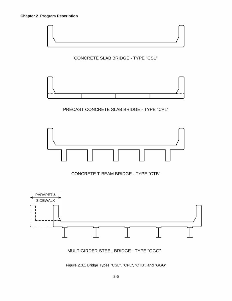
Chapter 2 Program Description
2-5
Figure 2.3.1 Bridge Types "CSL", "CPL", "CTB", and "GGG"
CONCRETE SLAB BRIDGE - TYPE "CSL"
CONCRETE T-BEAM BRIDGE - TYPE "CTB"
PARAPET &SIDEWALK
MULTIGIRDER STEEL BRIDGE - TYPE "GGG"
PRECAST CONCRETE SLAB BRIDGE - TYPE "CPL"

Chapter 2 Program Description
2-6
Figure 2.3.2 Bridge Types "GFS" and "GFF"
PARAPET &SIDEWALK
CL OF GIRDER TO CURB (-)
FLOORBEAM
1 2 3 4 5 6
STRINGER GIRDER
GIRDER FLOORBEAM STRINGER STEEL BRIDGE - TYPE "GFS"
FLOORBEAM
STRINGERGIRDER
GIRDER FLOORBEAM STRINGER STEEL BRIDGE - TYPE "GFS"
GIRDER
FLOORBEAM
GIRDER FLOORBEAM STEEL BRIDGE - TYPE "GFF"
1 2 3 4 5 6
CL OF GIRDER TO CURB (-)
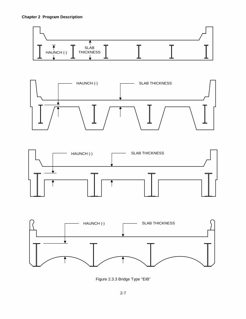
Chapter 2 Program Description
2-7
Figure 2.3.3 Bridge Type "EIB"
HAUNCH (-)SLAB
THICKNESS
SLAB THICKNESSHAUNCH (-)
HAUNCH (-) SLAB THICKNESS
HAUNCH (-) SLAB THICKNESS

Chapter 2 Program Description
2-8
Figure 2.3.4 Bridge Types "TFS" and "TFF"
TRUSS FLOORBEAM STRINGER STEEL BRIDGE - TYPE "TFS"
1 2 3 4 5
CL OF TRUSS TO CURB (+)
STRINGER
FLOORBEAMC LO
F TR
USS
FLOORBEAM
TRUSS FLOORBEAM STEEL BRIDGE - TYPE "TFF"
TRUSS SPACING
CL TRUSS
TRUSS SPACING

Chapter 2 Program Description
2-9
Figure 2.3.5 Bridge Types "FSS" and "GGF"
STRINGER
FLOORBEAM STRINGER STEEL BRIDGE - TYPE "FSS"
FLOORBEAM
1 2 43 5 76 8 9 10 11
FLOORBEAM
MULTIGIRDER FLOORBEAM STEEL BRIDGE - TYPE "GGF"
GIRDER
COLUMN
COLUMN

Chapter 2 Program Description
2-10
LIVE LOADINGS
Fifteen standard live loadings (LIVE LOAD = A to T) are built into the program. These are designated as H20, HS20,
HS25, AML (Alternate Military Load), IML (Increased Military Load), ML80, TK527, P-82 (204 Kips Permit Vehicle),
Type 3 Unit, Type 3S2 Unit, Type 3-3 Unit, PA58, EV2 (FAST Act Emergency Vehicle), EV3 (FAST Act Emergency
vehicle), and SU6TV (FAST Act Heavy-Duty Tow and Recovery Vehicle). See Figure 2.4.1 on page 2-11. The
loadings H20 and HS20 are described in the AASHTO Specifications. An ML80 is the maximum legal load in
Pennsylvania. The TK527 is a new posting vehicle effective January 1, 2002. The axle weights of ML80 and TK527 include 3% additional for scale tolerance. The Type 3 Unit, Type 3S2 Unit, and Type 3-3 Unit are
AASHTO typical legal loads which controls weight limits for short-span, medium-span, and long-span bridges, respectively. The PA58 is for risk-based posting. EV2, EV3, and SU6TV are described in FAST Act
effective December 4, 2015. For each loading, one unit of truck is considered in each lane that is loaded. The HS25
loading is a 25% higher loading than the HS20 loading. For loadings H20, HS20, and HS25, an equivalent lane
loading (uniform load and one or two concentrated floating loads) is also considered and the governing effects are
stored. Equivalent lane loadings for loadings H20 and HS20 are shown in the AASHTO Specifications. Like an
HS25 truck, an HS25 lane loading is also 25% higher than the HS20 lane loading. The program provides options
to analyze a bridge for different groups of these loadings. These options are explained in the Chapter 5 Input Data
Requirements of this manual.
In place of standard loadings described above, the bridge can also be analyzed for a maximum of eight special
loadings that can be described by entering various parameters of the loadings. This may be useful in analyzing a
permit load or a set of loadings customized by the user when it may be necessary to consider more than one unit
of standard loading in a lane. A special live load may have 2 to 80 axles for a truck loading and an associated lane
loading.
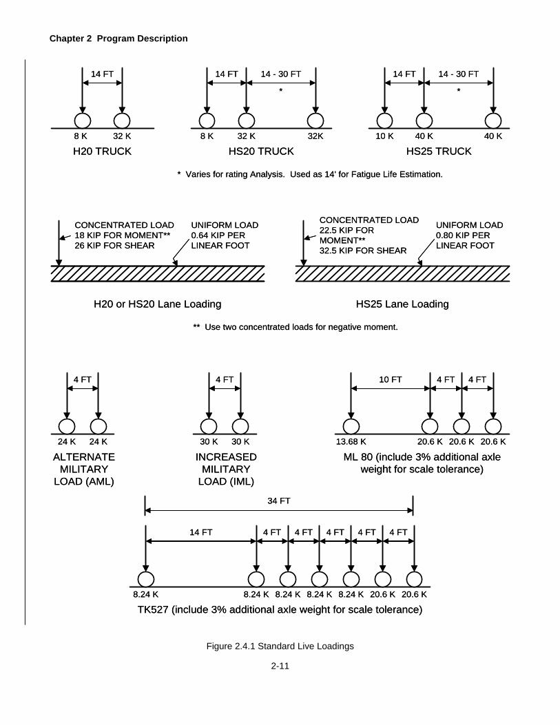
Chapter 2 Program Description
2-11
14 FT
32 K8 K
H20 TRUCK HS20 TRUCK
14 FT
32 K8 K
14 - 30 FT
32K
14 FT
40 K10 K
14 - 30 FT
40 K
HS25 TRUCK
UNIFORM LOAD0.64 KIP PERLINEAR FOOT
CONCENTRATED LOAD18 KIP FOR MOMENT**26 KIP FOR SHEAR
H20 or HS20 Lane Loading
** Use two concentrated loads for negative moment.
24 K
4 FT
24 K
ALTERNATEMILITARY
LOAD (AML)
30 K
4 FT
30 K
INCREASEDMILITARY
LOAD (IML)
*
* Varies for rating Analysis. Used as 14' for Fatigue Life Estimation.
*
HS25 Lane Loading
CONCENTRATED LOAD22.5 KIP FOR MOMENT**32.5 KIP FOR SHEAR
UNIFORM LOAD0.80 KIP PERLINEAR FOOT
10 FT
20.6 K13.68 K
4 FT
20.6 K
4 FT
20.6 K
ML 80 (include 3% additional axle weight for scale tolerance)
14 FT
8.24 K8.24 K
4 FT
8.24 K
4 FT
8.24 K
TK527 (include 3% additional axle weight for scale tolerance)8.24 K
4 FT 4 FT
20.6 K
4 FT
20.6 K
34 FT
14 FT
32 K8 K
H20 TRUCK HS20 TRUCK
14 FT
32 K8 K
14 - 30 FT
32K
14 FT
40 K10 K
14 - 30 FT
40 K
HS25 TRUCK
UNIFORM LOAD0.64 KIP PERLINEAR FOOT
CONCENTRATED LOAD18 KIP FOR MOMENT**26 KIP FOR SHEAR
H20 or HS20 Lane Loading
** Use two concentrated loads for negative moment.
24 K
4 FT
24 K
ALTERNATEMILITARY
LOAD (AML)
30 K
4 FT
30 K
INCREASEDMILITARY
LOAD (IML)
*
* Varies for rating Analysis. Used as 14' for Fatigue Life Estimation.
*
HS25 Lane Loading
CONCENTRATED LOAD22.5 KIP FOR MOMENT**32.5 KIP FOR SHEAR
UNIFORM LOAD0.80 KIP PERLINEAR FOOT
10 FT
20.6 K13.68 K
4 FT
20.6 K
4 FT
20.6 K
ML 80 (include 3% additional axle weight for scale tolerance)
14 FT
8.24 K8.24 K
4 FT
8.24 K
4 FT
8.24 K
TK527 (include 3% additional axle weight for scale tolerance)8.24 K
4 FT 4 FT
20.6 K
4 FT
20.6 K
34 FT
Figure 2.4.1 Standard Live Loadings
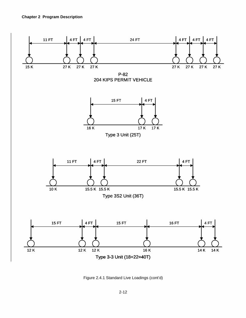
Chapter 2 Program Description
2-12
11 FT 4 FT
15.5 K15.5 K10 K
Type 3S2 Unit (36T)
22 FT
15.5 K
4 FT
15.5 K
15 FT 4 FT
12 K12 K12 K
15 FT
14 K
16 FT
16 K 14 K
4 FT
Type 3 Unit (25T)
15 FT 4 FT
16 K 17 K 17 K
11 FT 4 FT
27 K27 K15 K
P-82204 KIPS PERMIT VEHICLE
27 K
24 FT
27 K
4 FT4 FT
27 K
4 FT
27 K
4 FT
27 K
Type 3-3 Unit (18+22=40T)Type 3-3 Unit (18+22=40T)
11 FT 4 FT
15.5 K15.5 K10 K
Type 3S2 Unit (36T)
22 FT
15.5 K
4 FT
15.5 K
15 FT 4 FT
12 K12 K12 K
15 FT
14 K
16 FT
16 K 14 K
4 FT
Type 3 Unit (25T)
15 FT 4 FT
16 K 17 K 17 K
11 FT 4 FT
27 K27 K15 K
P-82204 KIPS PERMIT VEHICLE
27 K
24 FT
27 K
4 FT4 FT
27 K
4 FT
27 K
4 FT
27 K
Type 3-3 Unit (18+22=40T)
Figure 2.4.1 Standard Live Loadings (cont’d)

Chapter 2 Program Description
2-13
PA 58
15 FT 4 FT
20 K 21.4 K 21.4 K
15 FT
24 K 33.5 K
EV2 (Single Rear Axle Emergency Vehicle)
EV3 (Tandem Rear Axle Emergency Vehicle)
15 FT 4 FT
24 K 31 K 31 K
PA 58
15 FT 4 FT
20 K 21.4 K 21.4 K
15 FT
24 K 33.5 K
EV2 (Single Rear Axle Emergency Vehicle)
EV3 (Tandem Rear Axle Emergency Vehicle)
15 FT 4 FT
24 K 31 K 31 K
Figure 2.4.1 Standard Live Loadings (cont’d)
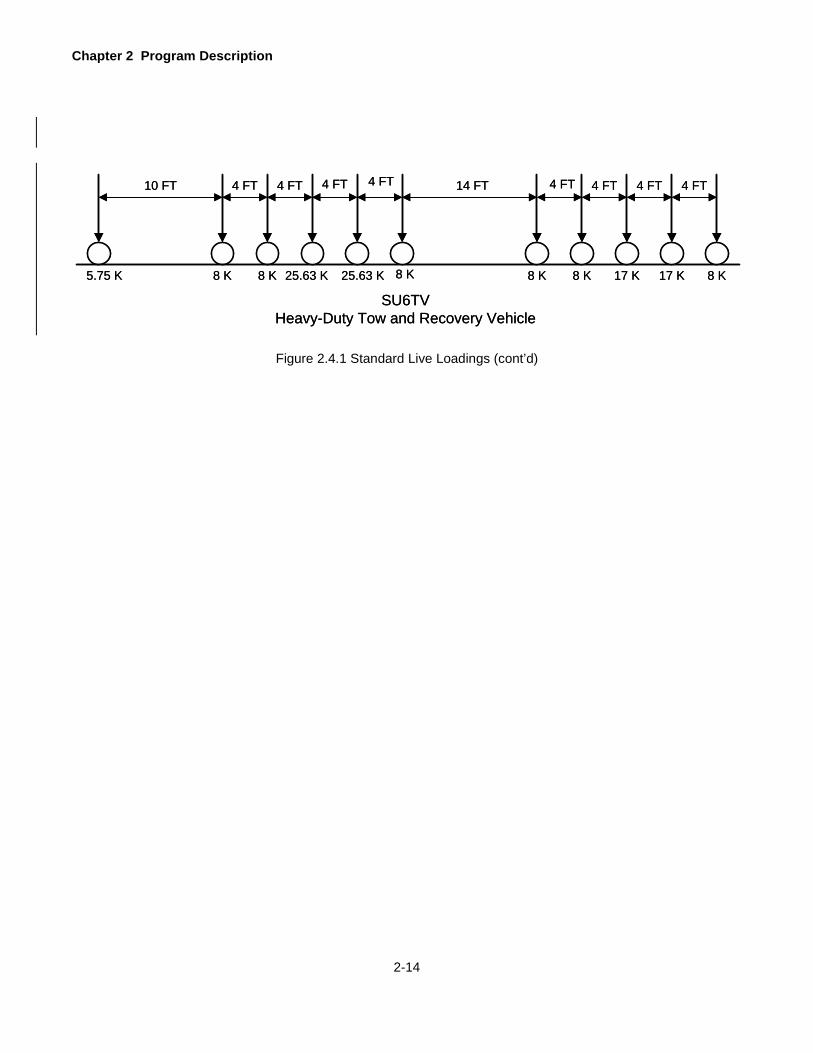
Chapter 2 Program Description
2-14
10 FT 4 FT
8 K8 K5.75 K
SU6TVHeavy-Duty Tow and Recovery Vehicle
8 K
14 FT
17 K
4 FT4 FT
25.63 K
4 FT
17 K
4 FT
8 K
4 FT4 FT 4 FT
25.63 K 8 K 8 K
10 FT 4 FT
8 K8 K5.75 K
SU6TVHeavy-Duty Tow and Recovery Vehicle
8 K
14 FT
17 K
4 FT4 FT
25.63 K
4 FT
17 K
4 FT
8 K
4 FT4 FT 4 FT
25.63 K 8 K 8 K
Figure 2.4.1 Standard Live Loadings (cont’d)

3-1
METHOD OF SOLUTION
The primary purpose of this program is to calculate the load ratings of a bridge in accordance with the AASHTO
Manual. The load ratings are calculated by performing the structural analysis of all primary members of a bridge.
This structural analysis is referred to as the rating analysis. The rating analysis is performed by carrying out the
following calculations.
1. Calculate Section Properties.
2. Calculate Dead Load Effects.
3. Calculate Maximum Live Load Plus Impact Effects.
4. Calculate Member Stresses and Strengths.
5. Rate Section by criteria set forth in AASHTO Manual.
The program performs above calculations using the classical methods of structural analysis. The program employs
the principles of statics for simple span girders and trusses, and the flexibility matrix method for a continuous girder
or truss. The live load analysis is performed using the influence line method. The ratings are computed based on
the Allowable Stress Method and the Load Factor Method.

Chapter 3 Method of Solution
3-2
NOTATIONS
The following are the meanings of notations used in various expressions in this section.
A = Area of cross section under consideration.
A b = Area of I-beam.
A c = Area of cross section of R.C. Slab, Precast Slab, or R.C. T-Beam.
A f = Area of flange.
A f = Area of one fastener, bolt or rivet.
A g = Total gross area of steel for all elements.
A i = Area of steel for element i.
A n = Area of net section.
A s = Area of tension reinforcement.
A sf = Area of reinforcement to develop compressive strength of overhanging flanges of I- and T-sections.
A s’ = Area of compression reinforcement.
A vb = Area of shear reinforcement (bent up bars).
A vs = Area of shear reinforcement (both legs of stirrup).
ADTT = Average daily truck traffic.
b = Web thickness of R.C. T-beam.
b = Beam flange width.
b w = Web thickness of concrete member.
b ’ = Width of projecting flange element.
B = Effective width of slab.
c = Distance from the extreme bottom fiber of steel to the neutral axis of the steel section of encased I-
beam.
C = Web buckling coefficient.
C b = Moment correction factor
C bot = Distance from the extreme bottom fiber of steel to the neutral axis.
C conc = Distance from the extreme fiber of concrete to the neutral axis.
C m = Bending compression interaction coefficient.
C reinf = Distance from the centroid of reinforcement to the neutral axis.
C top = Distance from the extreme top fiber of steel to the neutral axis.
d = Distance from extreme compression fiber to centroid of tension reinforcement.
d = Depth of steel beam or girder.
d = Depth of encased I-beam.
d = Nominal diameter of the fastener.
d ’ = Distance from extreme compression fiber to centroid of compression reinforcement.
d ’ = Distance from bottom of encased I-beam to bottom of slab.
d i = Distance from center of gravity of element i to the bottom.
d 0 = Spacing of intermediate stiffener.
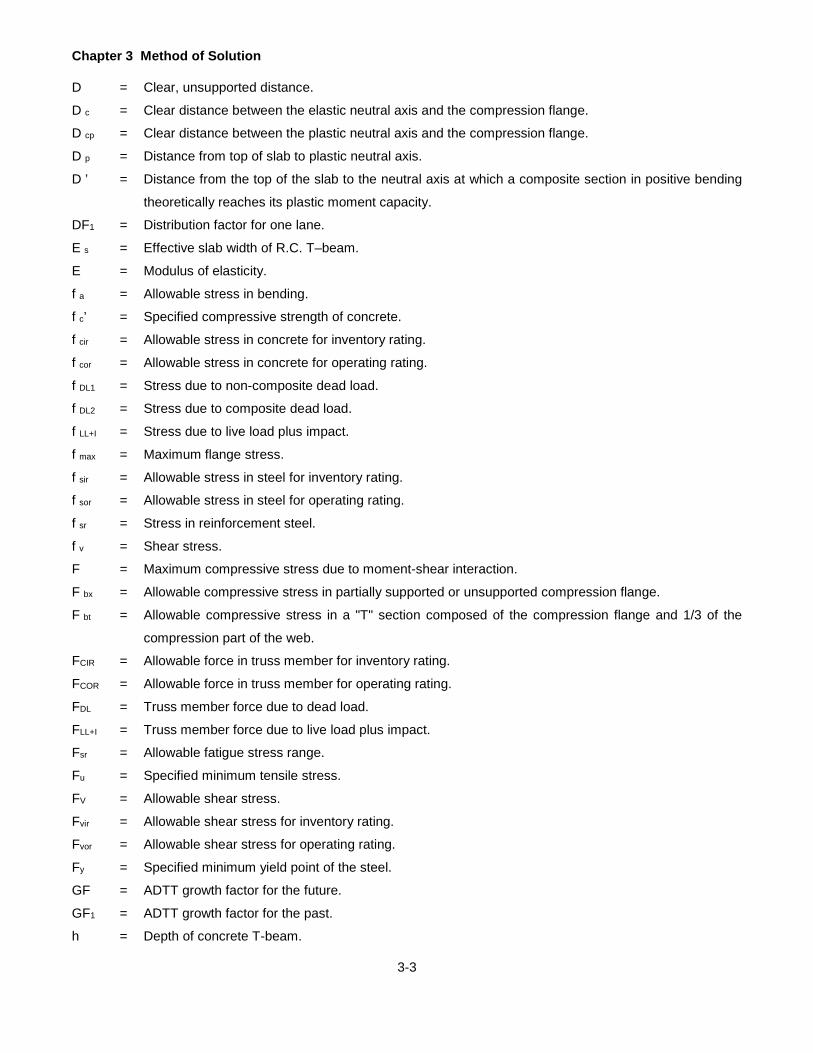
Chapter 3 Method of Solution
3-3
D = Clear, unsupported distance.
D c = Clear distance between the elastic neutral axis and the compression flange.
D cp = Clear distance between the plastic neutral axis and the compression flange.
D p = Distance from top of slab to plastic neutral axis.
D ’ = Distance from the top of the slab to the neutral axis at which a composite section in positive bending
theoretically reaches its plastic moment capacity.
DF1 = Distribution factor for one lane.
E s = Effective slab width of R.C. T–beam.
E = Modulus of elasticity.
f a = Allowable stress in bending.
f c’ = Specified compressive strength of concrete.
f cir = Allowable stress in concrete for inventory rating.
f cor = Allowable stress in concrete for operating rating.
f DL1 = Stress due to non-composite dead load.
f DL2 = Stress due to composite dead load.
f LL+I = Stress due to live load plus impact.
f max = Maximum flange stress.
f sir = Allowable stress in steel for inventory rating.
f sor = Allowable stress in steel for operating rating.
f sr = Stress in reinforcement steel.
f v = Shear stress.
F = Maximum compressive stress due to moment-shear interaction.
F bx = Allowable compressive stress in partially supported or unsupported compression flange.
F bt = Allowable compressive stress in a "T" section composed of the compression flange and 1/3 of the
compression part of the web.
FCIR = Allowable force in truss member for inventory rating.
FCOR = Allowable force in truss member for operating rating.
FDL = Truss member force due to dead load.
FLL+I = Truss member force due to live load plus impact.
Fsr = Allowable fatigue stress range.
Fu = Specified minimum tensile stress.
FV = Allowable shear stress.
Fvir = Allowable shear stress for inventory rating.
Fvor = Allowable shear stress for operating rating.
Fy = Specified minimum yield point of the steel.
GF = ADTT growth factor for the future.
GF1 = ADTT growth factor for the past.
h = Depth of concrete T-beam.

Chapter 3 Method of Solution
3-4
I b = Moment of inertia of basic steel section for encased I-beam.
I c = Moment of inertia of cracked section for encased I-beam.
I i = Moment of inertia of element i.
I U = Moment of inertia of uncracked section for encased I-beam.
I xx = Moment of inertia of section about the X-X axis.
I yy = Moment of inertia of section about the Y-Y axis.
I yc = Moment of inertia of compression flange about the vertical axis in the plane of the web.
IM = Vehicular dynamic load allowance
IR = Inventory rating factor.
J = [(bt3)c + (bt3)t + Dtw3]/3, where b and t represent the flange width and thickness of the compression and
tension flange, D is the web depth, and tw is the web thickness.
k = Buckling coefficient.
L = Length of unsupported flange between lateral connections, knee braces, and or other points of support.
L b = Unbraced length.
m = Number of years between year built and year of ADTT count for fatigue analysis.
M = Maximum bending moment.
M c = Moment capacity of the section.
MCIR = Moment capacity of the section for inventory rating.
MCOR = Moment capacity of the section for operating rating.
MDL = Moment due to dead load.
MDL1 = Moment due to non-composite dead load.
MDL2 = Moment due to composite dead load.
MLL+I = Moment due to live load plus impact.
MO = Moment strength based on overload provisions.
MP = Full plastic moment of section.
MU = Maximum bending strength.
MUD = Maximum bending strength for deck.
MUT = Maximum bending strength for tension.
MY = Moment capacity at first yield of the composite positive moment section, Fy times SLL+l.
M1 = Smaller moment at the end of the unbraced length.
M2 = Larger moment at the end of the unbraced length.
n = Ratio of modulus of elasticity of steel to that of concrete.
n 1 = Year of first ADTT count for fatigue life analysis.
n 2 = Year of second ADTT count for fatigue life analysis.
OR = Operating Rating factor.
r ’ = Radius of gyration of the compression flange about the Y-Y axis of web.
r t = Radius of gyration of a T-section comprising flange and one-third of the web in compression.

Chapter 3 Method of Solution
3-5
r y = Radius of gyration of the entire section about the Y-Y axis.
R = Remaining fatigue life in years.
R = Reduction factor for hybrid section.
R = Reduction factor for allowable compression in unbraced section.
RF = Rating factor.
RFM = Rating factor for moment.
RFMC = Rating factor for moment, compression flange yielding.
RFMD = Rating factor for moment, concrete in deck yielding.
RFMT = Rating factor for moment, tension flange yielding.
RFMV = Rating factor for moment-shear interaction.
RFO = Rating factor based on overflow provisions.
RFV = Rating factor for shear.
s = Stirrup spacing.
S = Section modulus.
SB = Section modulus for bottom fiber of steel section.
SC = Section modulus for top fiber of concrete.
SDL1 = Section modulus for non-composite dead load.
SDL2 = Section modulus for composite dead load.
SLL+I = Section modulus for live load plus impact.
SR = Section modulus for steel reinforcement in composite section.
SS = Section modulus for tension steel in concrete slab or T-beam.
SSC = Section modulus for compression steel in concrete slab.
ST = Section modulus for top fiber of steel section.
SL = Safe load capacity.
SLC = Safe load capacity rating factor.
SxC = Section modulus with respect to the compression flange.
t = Flange thickness.
t = Effective slab thickness.
t = Thickness of the connected material.
t s = Slab thickness.
t w = Web thickness.
v = Shear stress at a section.
v c = Allowable shear stress in concrete.
v cir = Permissible shear stress carried by concrete for inventory rating.
v cor = Permissible shear stress carried by concrete for operating rating.
v s = Allowable shear stress in steel.
V = Shearing force.
VC = Shear capacity of a section.

Chapter 3 Method of Solution
3-6
VCIR = Shear capacity of a section for inventory rating.
VCOR = Shear capacity of a section for operating rating.
VDL = Shear due to dead load.
VDL1 = Shear due to non-composite dead load.
VDL2 = Shear due to composite dead load.
VLL+I = Shear due to live load plus impact.
VP = Shear yielding strength of the web.
Vsir = Nominal shear strength provided by shear reinforcement for inventory rating.
Vsor = Nominal shear strength provided by shear reinforcement for operating rating.
VU = Shear capacity of a section.
w = Effective width of composite section for encased I-beam divided by modular ratio n.
x = Depth of neutral axis for reinforced concrete section.
x = Location of neutral axis of a steel section measured from the bottom of the section.
x i = Location of neutral axis of element i.
y tc = Depth of uncracked section of encased I-beam.
Z = Plastic section modulus.
α = Angle of bent up bars to be used as shear reinforcement.
α = Factor for effective fatigue stress range.
γ = Summation factor for effective fatigue stress range.
∆ = Remaining fatigue cycles.
λ = Projected fatigue cycles.

Chapter 3 Method of Solution
3-7
SECTION PROPERTIES
Section properties are required to solve for reactions in a continuous member and to calculate deflections, stresses
and strengths for all members. Various section properties (cross sectional area, moment of inertia, section moduli,
etc.) are computed from the dimensions entered through input forms provided for various members of a bridge. The
program will compute the section properties on both sides of the cutoff for analyzing and rating each section. Direct
formulas and iterative processes are used for calculations of these properties as explained in this section.
3.2.1 R. C. Slab and Precast Concrete Slab
Refer to Figure 3.2.1 on page 3-9.
The cross-sectional area to be used in calculating the weight of the member is calculated by:
.144
)t)(B(A s
c = where B = 12.0” for R. C. Slab
The depth of neutral axis, x, is computed by solving the following equation: 0dnAdA1n2xnAA1n2xB ssss
22
1 =−−−+−+ '')(]')[(
The moment of inertia of transformed section (steel areas converted into equivalent concrete area) is
computed by: 2
s2
s3
31
c xdnAdxA1n2Bx )()'(')( −+−−+=Ι
The section modulus for top fiber of concrete is computed by:
x
S cc
Ι=
The section modulus for tension steel is computed by:
)( xdn
S cs −
=Ι
The section modulus for compression steel (if present) is computed by:
)'( dxn2
S csc −
=Ι
3.2.2 R. C. T-Beam
Refer to Figure 3.2.1 on page 3-9.
Effective slab width, Es, is computed as the minimum of the following three values:
1. Center-to-center spacing of beams in inches.
2. 12 (t) + b where b = web thickness.
3. One-fourth the span length in inches.
The cross-sectional area to be used in calculating the weight of the member is calculated by:
))(())(( ssc tspacingbthA +−=

Chapter 3 Method of Solution
3-8
The initial depth of neutral axis, x i is computed neglecting the area of web above the neutral axis:
sss
ss2
s21
i nAA1n2tEdnAdA1n2tEx
+−++−+
=')(
'')()(
If x i is less than or equal to t, the actual depth of neutral axis, x, is computed by solving the following
equation:
0dnAdA1n2xnAA1n2xE ssss2
s21 =−−−+−+ '')(]')[(
If x i is greater than t, the actual depth of neutral axis, x, is computed by solving the following equation:
0dnAdA1n2tExnAA1n2tbtExb ss2
s21
sss2
21 =−−−−+−+−+ '')()(]')()([)(
The moment of inertia of the section is computed by: 2
s2
s3
312
2t
s3
s121
c xdnAdxA1n2txbxtEtE )()'')())(()( −+−−+−+−+=Ι
Various section moduli are then computed using the equations given in Section 3.2.1, R. C. Slab and
Precast Concrete Slab.
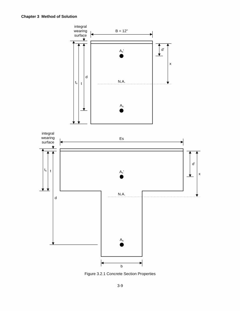
Chapter 3 Method of Solution
3-9
Figure 3.2.1 Concrete Section Properties
As
B = 12"integral wearing surface
As' d'
d
tts
As
As'
Es
tts
d
integral wearing surface
d'
b
x
x
N.A.
N.A.

Chapter 3 Method of Solution
3-10
3.2.3 Girder, Floorbeam or Stringer
Non-composite section properties for DL1 and/or DL2, composite section properties (n) for DL2, composite section properties (3n) for live load, and composite section properties at negative bending moment region will be computed by the PennDOT Beam Section Properties (BSP) program.
The effective slab width for a composite section is taken as the minimum of the following three values:
1. Center-to-center spacing of member in inches.
2. Twelve times the effective slab thickness (total slab thickness -½" integral wearing surface).
3. One-fourth the span length in inches.
The effective slab width is then divided by a modular ratio (3n for section properties for DL2. and n for
section properties for LL + I). The effective slab thickness is computed by subtracting one-half inch from
the total slab thickness entered.
If the section is non-composite, the effective slab width is not computed and only the section properties for
a steel section are computed as explained next.
All equations used in calculating the section properties are not given here since they vary with the type and
details of a section. However, the basic steps involved and some generic equations are given here.
Examples of detailed calculations for various situations can be found in any standard textbook on structural
steel design.
The location of neutral axis measured from the bottom of the section is given by:
g
ii
AdAx ∑=
Where A i is the area and d i is the distance of the center of gravity of the element i from the bottom.
The moment of inertia of the section about the neutral axis is given by:
∑ += )( 2iiixx xAΙΙ
Where Ιi is the moment of inertia of element i about its own center of gravity and x i is the distance of the
element's center of gravity from the neutral axis of the section.
In calculating x and Ιxx for a composite section subjected to a negative moment, the concrete area in tension
is neglected. Also, for a composite section subjected to positive moment, the width of the effective slab is
divided by n or 3n to convert the concrete area into equivalent steel area.
The section moduli for various locations of the section are then computed by:
top
xxT C
S Ι= (Section modulus at the top of steel section)

Chapter 3 Method of Solution
3-11
bot
xxB C
S Ι= (Section modulus at the bottom of steel section)
conc
xxC C
S Ι= (Section modulus at the top of slab – positive moment section)
infre
xxR C
S Ι= (Section modulus at the center of gravity of reinf. – negative moment section)
In addition to above section properties, the program also computes the following section properties that are
required for Load Factor Method. These properties are not printed out, but are used for intermediate
calculations to determine whether the section is compact, braced non-compact or unbraced non-compact.
These properties are the moment of inertia of the section about Y-Y axis, Ιyy, the radius of gyration of the
entire section about Y-Y axis, r y the radius of gyration of a T–section comprising one-third of the web and
whole flange on compression side of section beyond elastic neutral axis, r t and the radius of gyration of the
compression flange about the Y-Y axis of web, r '.
Ιyy is computed in the same manner as Ιxx except the Y-Y axis of the section is considered.
The radius of gyration is computed by:
Ar yy
y
Ι=
Where A is the area of cross section under consideration. Refer to Figure 3.2.2 on page 3-12.
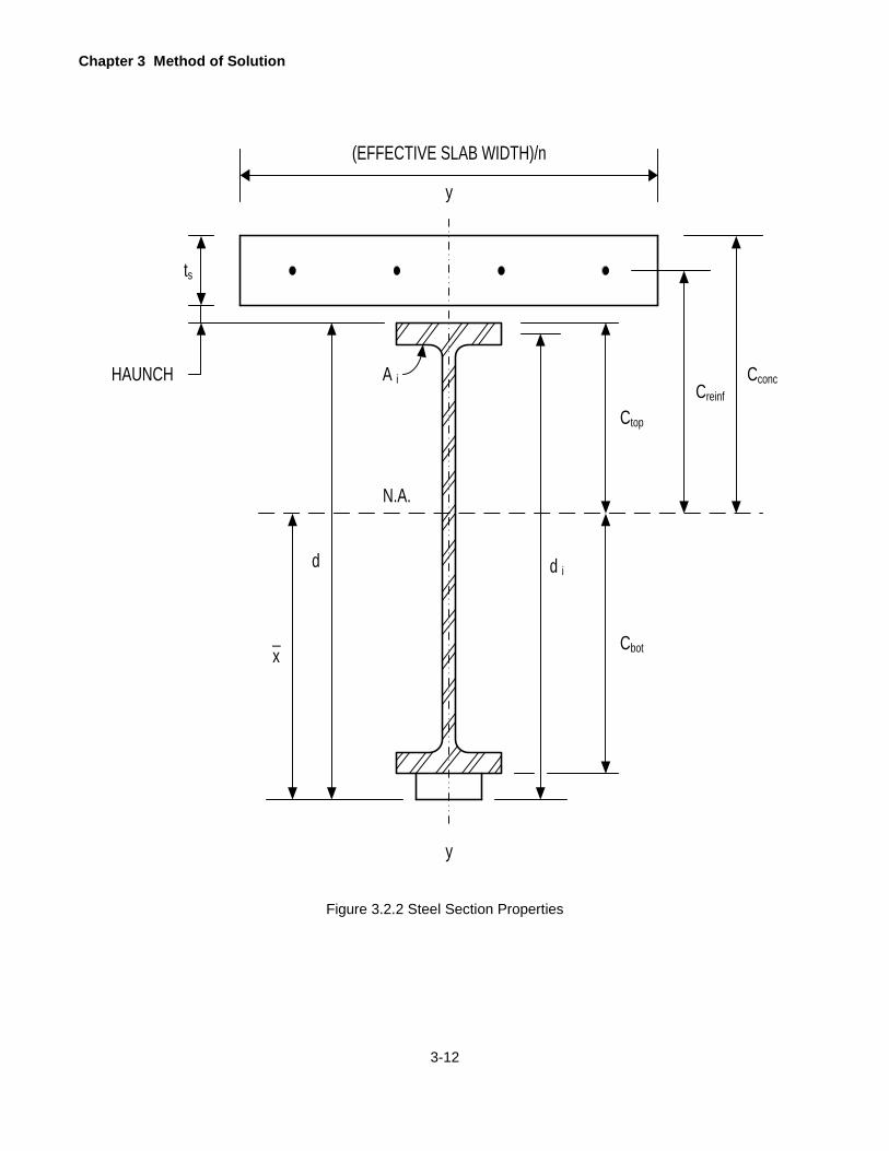
Chapter 3 Method of Solution
3-12
Figure 3.2.2 Steel Section Properties
(EFFECTIVE SLAB WIDTH)/n
ts
HAUNCH
N.A.
A i
y
y
Cconc
Ctop
Creinf
d id
xCbot
_
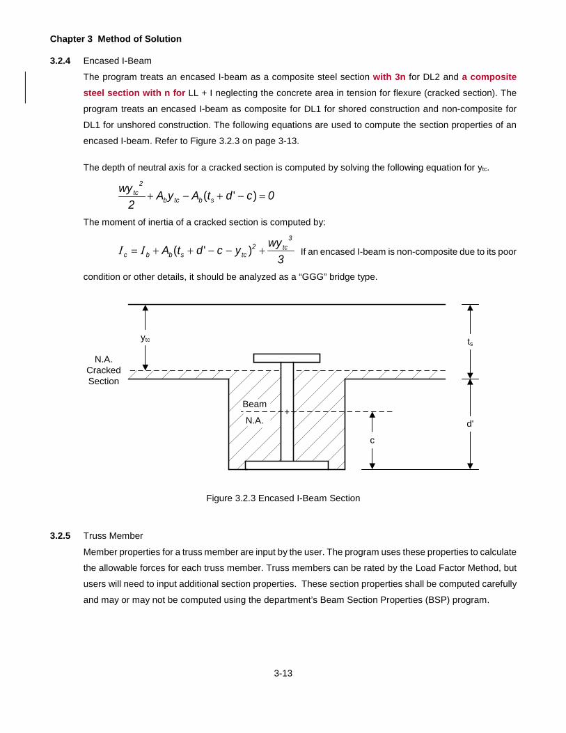
Chapter 3 Method of Solution
3-13
3.2.4 Encased I-Beam
The program treats an encased I-beam as a composite steel section with 3n for DL2 and a composite steel section with n for LL + I neglecting the concrete area in tension for flexure (cracked section). The
program treats an encased I-beam as composite for DL1 for shored construction and non-composite for
DL1 for unshored construction. The following equations are used to compute the section properties of an
encased I-beam. Refer to Figure 3.2.3 on page 3-13.
The depth of neutral axis for a cracked section is computed by solving the following equation for ytc.
0cdtAyA2
wysbtcb
2tc =−+−+ )'(
The moment of inertia of a cracked section is computed by:
3wyycdtA
3tc2
tcsbbc +−−++= )'(ΙΙ If an encased I-beam is non-composite due to its poor
condition or other details, it should be analyzed as a “GGG” bridge type.
Figure 3.2.3 Encased I-Beam Section
3.2.5 Truss Member
Member properties for a truss member are input by the user. The program uses these properties to calculate
the allowable forces for each truss member. Truss members can be rated by the Load Factor Method, but
users will need to input additional section properties. These section properties shall be computed carefully
and may or may not be computed using the department’s Beam Section Properties (BSP) program.
N.A.CrackedSection
ytc
c
d'
ts
Beam
N.A.+
Chapter 3 Method of Solution
3-14
CONTINUOUS STRUCTURE ANALYSIS
A continuous structure can be analyzed by various conventional methods of structural analysis such as slope-
deflection, moment distribution, stiffness matrix or flexibility matrix method. The latter methods are suitable for
computer applications because they are based on matrix algebra. BAR7 uses the modified flexibility method that
was developed by the author. This section explains how the program utilizes this method to analyze a continuous
girder, a continuous truss and a cantilever truss.
3.3.1 Continuous Girder
A continuous girder is a statically indeterminate structure. It is statically indeterminate because there are
more unknown reactions than can be determined by the application of the condition equations for static
equilibrium. The first step in analyzing a girder is to determine the support reactions. If reactions are known,
then the moment and shear at any section can be easily calculated by statics. In the flexibility method, the
reactions are solved by formulating as many simultaneous equations as there are supports. Two equations
can easily be formed by summation of all vertical forces to zero and summation of all moments about a
given point equal to zero (equilibrium equations). Other equations are formed by knowing the fact that
deflections at all intermediate supports are zero (these are known as compatibility equations). If the girder
has in-span hinges, it is also known that the moments at these hinges are zero (because a hinge cannot
resist a moment). The modified flexibility method utilizes this additional information in formulating
simultaneous equations and solving them.
The equilibrium equations mentioned above are easy to set. However, the compatibility equations require
calculations of deflections in a simple span girder. A typical compatibility equation would state that the
deflection at an intermediate support point of a continuous beam when the support is removed must be
equal to the upward deflection caused by the unknown reaction at that support. If the deflection of a simply
supported beam, derived from a continuous beam by removing intermediate supports, can be found, then
the compatibility equation can be set.
The method described above is basically used to formulate these simultaneous equations and then these
equations are solved using matrix algebra.
3.3.2 Continuous Truss
The method utilized for analysis of a continuous truss is like the method used for a continuous girder without
hinges. The reactions are solved by formulating as many simultaneous equations as there are supports.
Two equilibrium equations are formed by setting the summation of all vertical loads to zero and the
summation of moments of all loads about the left most support equal to zero. The compatibility equations
are formed by setting the deflections at intermediate supports for a determinate truss equal to and opposite
in sign of deflections due to a vertical force applied at each support equal to unknown reaction. These

Chapter 3 Method of Solution
3-15
equations are then solved by matrix algebra. The deflections at intermediate supports for a determinate
truss are calculated using the method of virtual work.
3.3.3 Cantilever Truss
A cantilever truss is a continuous truss with in-span hinges. The program assumes that a cantilever truss
is a statically determinate truss, i.e. the truss has as many hinges as there are redundant reactions (Number
of supports = 2 + number of hinges). The reactions are solved by formulating as many simultaneous
equations as there are supports. The equations are formed by:
1. Setting the sum of all vertical loads equal to zero.
2. Setting the sum of moments for all vertical loads and reactions about the left most support equal to
zero.
3. Setting the moment of all loads and reactions about each hinge equal to zero.
These equations are then solved by matrix algebra. Once the reactions are known, member forces are
determined by method of joints and sections.

Chapter 3 Method of Solution
3-16
DEAD LOAD ANALYSIS
The program employs the following technique for dead load analysis of various bridge components.
3.4.1 Girder
Two types of dead loads act on a girder. The first load, hereinafter referred to as DL1, is the dead load that
acts on the non-composite section of the member. DL1 includes the load due to the weight of beam, girder,
slab, haunch, permanent formwork, stringers, floorbeams, diaphragms, bracings, stiffeners and other
hardware attached to the main member such as the girder or truss. The second load, hereinafter referred
to as DL2, is the dead load that acts on the composite section with 3n of the member. DL2 includes the
load due to the weight of parapet, sidewalk, median, railing, steel grid flooring, timber flooring, other
structures permanently attached to the deck, and the sidewalk live load. The engineer enters some of
these loads and some are computed by the program. This will be explained in detail later in this manual.
Each span of the girder is divided into ten (10) equal segments and a section (or analysis point) is
considered at each end of the segment (total of 11 sections in each span). For a simple span, the maximum
moments due to DL1 and DL2 are computed by applying the principles of statics. For a continuous span,
first the reactions at the supports are computed using the modified flexibility method developed by the
author. For this method, refer to Section 3.3.1 CONTINUOUS GIRDER. For computations of reactions due
to DL1, the moments of inertia of non-composite sections are used. For computations of reactions of EIB’s
shored construction due to DL1, the moments of inertia of composite sections with modular ratio equal to
3n are used. For computations of reactions due to DL2, the moments of inertia of composite sections with
modular ratio equal to 3N are used. The moments and shears at tenth points are then computed applying
the principles of statics.
3.4.2 Stringer
The method used for dead load analysis of a stringer is the same as that used for girder analysis. The
dead loads acting on the stringer are computed assuming all stringers equally carry the total dead load
acting on the deck. The weight of the slab acting on the stringer varies depending on the stringer spacing. The critical stringer in the specified span will carry the largest weight of slab due to the largest sum of the left and right stringer spacing.
3.4.3 Concrete Slab or T-Beam
For a concrete slab or T -beam, the dead load consists of weight of beam, deck, diaphragms, parapets,
median, railings and other structures permanently attached to the deck or beam. The maximum dead load
moment in the span is computed in the same manner described for simple span girders. For an analysis of
a concrete slab bridge, one-foot wide slab is considered.

Chapter 3 Method of Solution
3-17
3.4.4 Encased I-Beam
For an encased I-beam, the dead load consists of weight of beam, deck, interior and exterior diaphragms,
formwork, parapets, median, railings and other structures permanently attached to the deck or beam. The
maximum dead load moment in the span is computed in the same manner described for simple span
girders.
3.4.5 Truss
The engineer enters the dead loads acting on a truss as joint loads. The member forces in a simple span
truss are computed by the method of joints and sections. The member forces in a continuous span truss
are computed using the flexibility matrix method. For details on analysis of continuous truss by flexibility
matrix method, refer to Analysis of Framed Structures by Gere and Weaver.
3.4.6 Floorbeam
The dead loads acting on the floorbeam are due to the weight of deck, stringers, floorbeam, STRINGER DL1, FLOORBEAM DL1, and other loads described as DL2 in girder analysis.
For bridges without stringers (“GFF” and “TFF”), the total uniformly distributed DL1 dead loads (UDL1) along the floorbeams are floorbeam weights, deck weight*(corresponding floorbeam spacing), and FLOORBEAM DL1. The total uniformly distributed DL2 dead loads (UDL2) along the floorbeams are DL2*(corresponding floorbeam spacing).
For bridges with stringers (“FSS”, “GFS”, “GGF” and ”TFS”), the total uniformly distributed DL1 dead loads along the floorbeams are floorbeam weights and FLOORBEAM DL1. The total uniformly distributed DL2 dead loads along the floorbeams are 0. The reactions due to DL1 and DL2 computed in the stringer analysis phase are assumed to act as concentrated loads on the floorbeam. If simple stringers are on top of floorbeams, the total concentrated DL1 and DL2 dead loads from the stringers are computed by simple beam method. If continuous stringers are on top of floorbeams, the total concentrated DL1 and DL2 dead loads from the stringers are computed by the influence line method along the stringer spans.
To analyze half a floorbeam, the moment and shear due to dead loads is computed at the center of the
floorbeam span by simple beam method. If the floorbeam extends outside the main girder, truss, or support and if it is continuous, the moment at the center of the floorbeam is computed treating the outside
portion of the floorbeam as a cantilever.
In the case of patch loads acting on the floorbeam or unsymmetrical pier configuration, the entire floorbeam will be analyzed and the moment and shear at each analysis point are computed by CBA

Chapter 3 Method of Solution
3-18
program by simple beam method. The floorbeam can be analyzed as a simple span without cantilever, a continuous 2-span floorbeam with left or right cantilever, or a continuous 3-span floorbeam with left and right cantilevers.
3.4.7 Patch Load
The effects of two dead load types (DL1 and DL2) of concentrated or distributed patch loads are added to
the dead load for the computation of the overall dead load effects.
The patch loads for the primary members will be applied for the following bridge types:
1. The concrete member (C) of “CPL”, “CSL”, or “CTB”
2. The girder (G) of “EIB”, “GFF”, “GFS”, or “GGG”
3. The truss member (T) of “TFF”, “TFS”, or “TTT”
4. The floorbeam member (F) of “FSS”, “GFF”, “GFS”, “GGF”, “TFF”, or “TFS”
The distributed patch loads can be uniformly (rectangular shape) or linearly distributed (triangular or
trapezoidal shape).
The patch load acting on the concrete member, floorbeam, or girder will be analyzed by CBA (Continuous
Beam Analysis) to obtain the corresponding reactions, moments, and shears at all analysis points. These
values will be added into the corresponding dead load effect at all analysis points.
The patch loads acting on the truss are input by users and will be broken into panels. Each panel will have
its share of patch loads to be analyzed by assuming the left and right truss joints of the panel acting like a
simply supported beam to obtain the corresponding reactions at the left and right truss joints. Add all these
reactions from all panel analyses into user input truss joint dead loads.
Please note that the patch load for each member type will not impact to other member type. For example, a bridge type of “GFS”, the patch load applied to a floorbeam will not transfer the patch load to the girders.
Chapter 3 Method of Solution
3-19
LIVE LOAD ANALYSIS
The program uses the following techniques for live load analysis of various bridge components.
3.5.1 Beam, Stringer or Girder
A longitudinal beam type member (steel girder or stringer. reinforced concrete slab or T-beam or encased
I-beam) is analyzed for a live load using the influence line method. For this purpose, the member is divided
into ten (10) equal segments of each span. A unit vertical load is applied at each tenth point one at a time
and various effects (support reaction, shear, moment and deflection) are calculated at each of the tenth
points across the member. In calculating these effects, principles of statics are used for simple spans and
the modified flexibility method is used for continuous spans. These effects at a section due to a unit load at
other positions constitute an influence line. Each influence line is then separately analyzed for the maximum
live load effect. The method used for analyzing an influence line for the maximum live load effect is
explained later in this section.
3.5.2 Floorbeam
The maximum live load effect (moment or shear) at a given section in the floorbeam is calculated by
assuming the deck acting as a continuous (or simple) beam spanning over the floorbeam and the floorbeam
acting as a simple (or cantilever) beam spanning between (or over) the main girders or trusses. The
program also assumes that the loads are transferred to the floorbeam through the deck as if the stringers
do not exist.
To calculate the longitudinal effect (in the direction of traffic), the program starts calculating the
reactions at the floorbeam due to longitudinal movement of the truck or lane live load, then treating these
reactions as concentrated loads acting on the floorbeam. For bridges types without stringers (‘GFF’ and ‘TFF’) (i.e. the deck is supported directly by floorbeams) and the distribution factor for moment is entered (i.e. DFS_M > 0), the longitudinal effect on the floorbeam is calculated in accordance with 1996 AASHTO Specifications 3.23.3 Bending Moments in Floor Beams. The reaction on the floorbeam is calculated by multiplying the non-zero distribution factor for moment entered in the input with the maximum axle weight of the live load as per 1996 AASHTO Specifications Table 3.23.3.1. However, 1. for bridges types without stringers and the distribution factor for moment is not entered (i.e.DFS_M = 0), or 2. for bridge types with stringers (‘FSS’, ‘GFS’, ‘GGF’, & ‘TFS’) , the reaction on the floorbeam is calculated by the influence line method along the stringer spans as explained in Section 3.5.4 INFLUENCE LINE.
To calculate the transverse effect, the program starts with one lane and places it closest to the left curb (i.e. from the left curb to the right curb). Then it places the two concentrated loads (0.5 kip each, always at a
gage distance apart) within that lane with the left load at one-half the passing distance away from the left
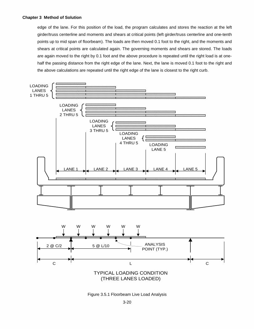
Chapter 3 Method of Solution
3-20
edge of the lane. For this position of the load, the program calculates and stores the reaction at the left
girder/truss centerline and moments and shears at critical points (left girder/truss centerline and one-tenth
points up to mid span of floorbeam). The loads are then moved 0.1 foot to the right, and the moments and
shears at critical points are calculated again. The governing moments and shears are stored. The loads
are again moved to the right by 0.1 foot and the above procedure is repeated until the right load is at one-
half the passing distance from the right edge of the lane. Next, the lane is moved 0.1 foot to the right and
the above calculations are repeated until the right edge of the lane is closest to the right curb.
Figure 3.5.1 Floorbeam Live Load Analysis
LOADINGLANES
1 THRU 5
LOADINGLANES
2 THRU 5LOADING
LANES3 THRU 5
LOADINGLANES
4 THRU 5 LOADINGLANE 5
LANE 1 LANE 2 LANE 3 LANE 4 LANE 5
C L C
2 @ C/2 5 @ L/10
W W W W W W
ANALYSISPOINT (TYP.)
TYPICAL LOADING CONDITION(THREE LANES LOADED)
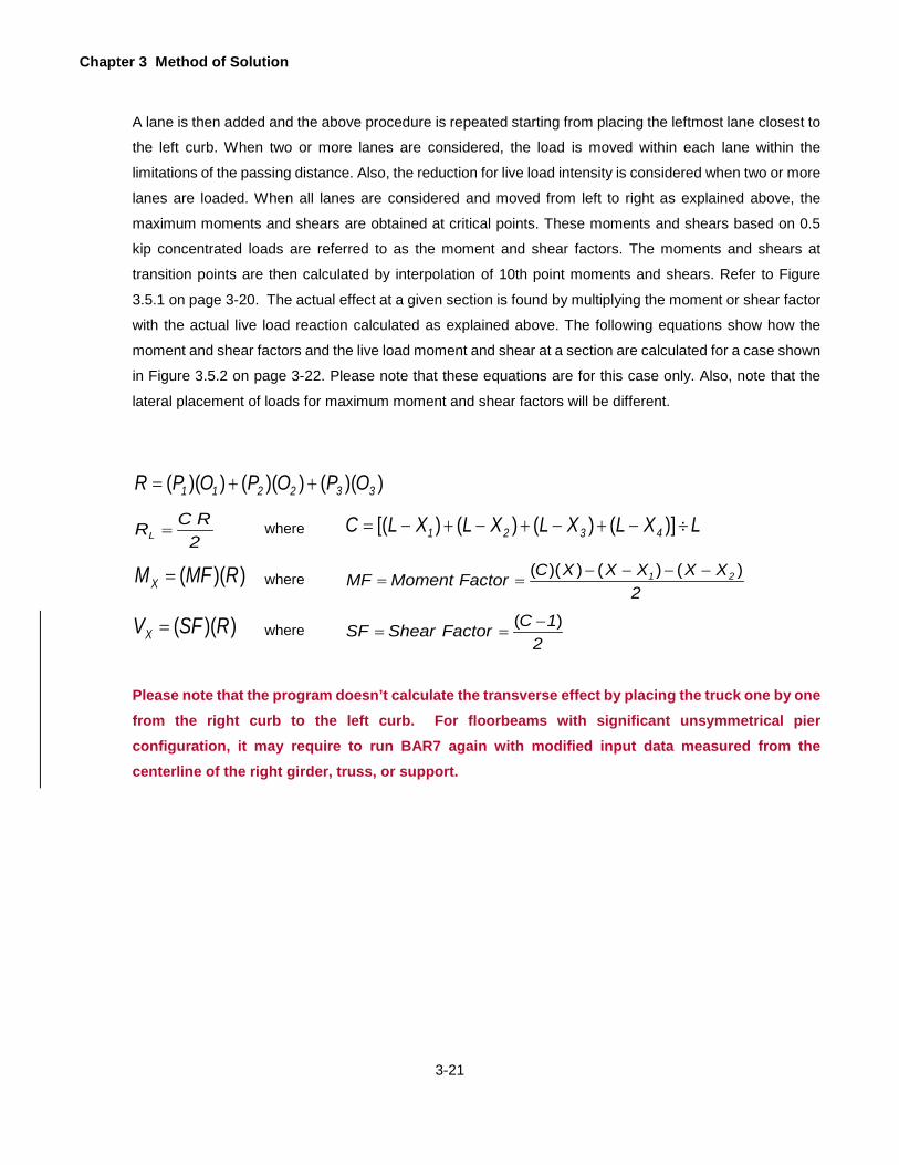
Chapter 3 Method of Solution
3-21
A lane is then added and the above procedure is repeated starting from placing the leftmost lane closest to
the left curb. When two or more lanes are considered, the load is moved within each lane within the
limitations of the passing distance. Also, the reduction for live load intensity is considered when two or more
lanes are loaded. When all lanes are considered and moved from left to right as explained above, the
maximum moments and shears are obtained at critical points. These moments and shears based on 0.5
kip concentrated loads are referred to as the moment and shear factors. The moments and shears at
transition points are then calculated by interpolation of 10th point moments and shears. Refer to Figure
3.5.1 on page 3-20. The actual effect at a given section is found by multiplying the moment or shear factor
with the actual live load reaction calculated as explained above. The following equations show how the
moment and shear factors and the live load moment and shear at a section are calculated for a case shown
in Figure 3.5.2 on page 3-22. Please note that these equations are for this case only. Also, note that the
lateral placement of loads for maximum moment and shear factors will be different.
))(())(())(( 332211 OPOPOPR ++=
2RCRL = where LXLXLXLXLC 4321 ÷−+−+−+−= )]()()()[(
))(( RMFMX = where 2
XXXXXCorFactMomentMF 21 )()())(( −−−−==
))(( RSFVX = where 2
1CFactorShearSF )( −==
Please note that the program doesn’t calculate the transverse effect by placing the truck one by one from the right curb to the left curb. For floorbeams with significant unsymmetrical pier configuration, it may require to run BAR7 again with modified input data measured from the centerline of the right girder, truss, or support.

Chapter 3 Method of Solution
3-22
Figure 3.5.2 Floorbeam Live Load Analysis
x1
R2
LOADING TWO LANES FOR MAXIMUM MOMENT
WHEELLOAD(TYP.)
CURBLINE(TYP.)
FB1
FB2
FB3
FB4
FB5
FB6
MAINGIRDER(TYP.)
FLO
OR
BE
AM
(TY
P.)
PLAN VIEW OF WHEEL LOAD POSITIONS
x x x xFB1 FB2 FB3 FB4
R
P1 P2 P3 (AXLE LOADS)
O1
O2
O3
R2
R2
R2
x2
x
x3
x4
RRRL
INFLUENCE LINE FOR REACTION AT FLOORBEAM 2
Chapter 3 Method of Solution
3-23
3.5.3 Truss
For live load analysis, trusses are divided into two categories. These are: A. Simple or continuous span
trusses without counters, and B. Simple span trusses with counters.
A simple or continuous span truss without counters is analyzed by the influence line method. For this, a
unit vertical load is applied one at a time at each upper or lower joint, depending upon whether it is a deck
truss or through truss, and the member forces are found using the method described above for the dead
load analysis. When all joints are loaded, the influence lines for member forces are generated. Each
influence line is then analyzed for the maximum live load effect by the method described later in this section.
For a simple span truss with counters, the actual live load is moved across the truss considering one joint
at a time and trying all possible load positions to produce the maximum and minimum effect. The analysis
begins with the assumption that the dead load forces are already present when the live load is applied. This
is important to assure the proper action of the diagonal (counter) for a given position of the live load. For
each joint, the following positions of the live load are tried. First, the axle number one is placed at the joint
under consideration and all other axles are placed to the left in their respective positions. For the axles that
fall between the joints, equivalent joint loads are computed assuming the panel to act as a simple span.
For this position of the load, the combined dead load plus live load forces are computed. The maximum
and minimum force is stored for each member. Next, the axle number two is placed over the joint and the
procedure described above is repeated. This process is continued until the last axle is over the joint. Then
the axles are placed such that the center of gravity of the all live loads coincides with the joint and the
member forces are computed again. Next, the axle loads are reversed and the whole procedure is
repeated. This gives the effects of the live load moving across the bridge in the other direction. When this
process is completed, the maximum and minimum member forces are obtained for each member. The
member forces in tension due to live load are obtained by algebraically subtracting the corresponding member forces in tension due to dead load from the maximum member forces in tension due to the combination of live load and dead load. The member forces in compression due to live load are obtained by algebraically subtracting the corresponding member forces in compression due to dead load from the minimum member forces in compression.
3.5.4 Influence Line
As described earlier, the influence lines are generated for moments in the girder and member forces in the
truss. Each influence line is then analyzed as described here to find the maximum live load effect. For this,
the influence line is divided into several regions. Each region consists of either all positive or all negative
ordinates. The area of each region, the absolute maximum (peak) ordinate in each region and its location
are found. For each peak of the influence line, the following is done. First, the axle number one is placed
over the peak and the other axles are placed to the left in their respective positions. The ordinates under
other axles are computed by interpolation assuming a straight-line variation of the influence line between

Chapter 3 Method of Solution
3-24
two consecutive ordinates. Each axle load is then multiplied by the ordinate under it. All positive values are
added and stored as a positive effect. Likewise, all negative values are added and stored as a negative
effect. The absolute maximum positive effect and the absolute maximum negative effect are stored. Next,
the second axle is placed over the peak and the above procedure is repeated. After the last axle is placed
over the peak, the axles are then placed such that the center of gravity of the load coincides with the location
of the peak. The positive and negative effects are found again and the maximum effects are stored. The
axle loads are then reversed (to consider the effect of the live load moving across the bridge in the other
direction) and the procedure described above is repeated. When this process is completed, the absolute
maximum positive and the absolute maximum negative live effects are obtained. These are then multiplied
by the distribution factor, reduction in live load intensity factor and impact factor to get the actual live load
plus impact effects.
The procedure described above is applicable for a truck load. However, for H or HS loading, the effects of
equivalent lane loading must also be investigated. To find the effects of lane loading (uniform load plus a
floating concentrated load), the sum of all positive and the sum of all negative areas of the influence line
are computed. Also, the absolute maximum positive ordinate and the absolute maximum negative ordinate
are found. To find the positive lane loading effect, the sum of positive areas is multiplied by the uniform
load and added to the product of the maximum positive ordinate and the applicable (moment or shear)
concentrated load in the same manner. The governing effects are stored. Refer to Figure 3.5.3 on page
3-25 and Figure 3.5.4 on page 3-26.
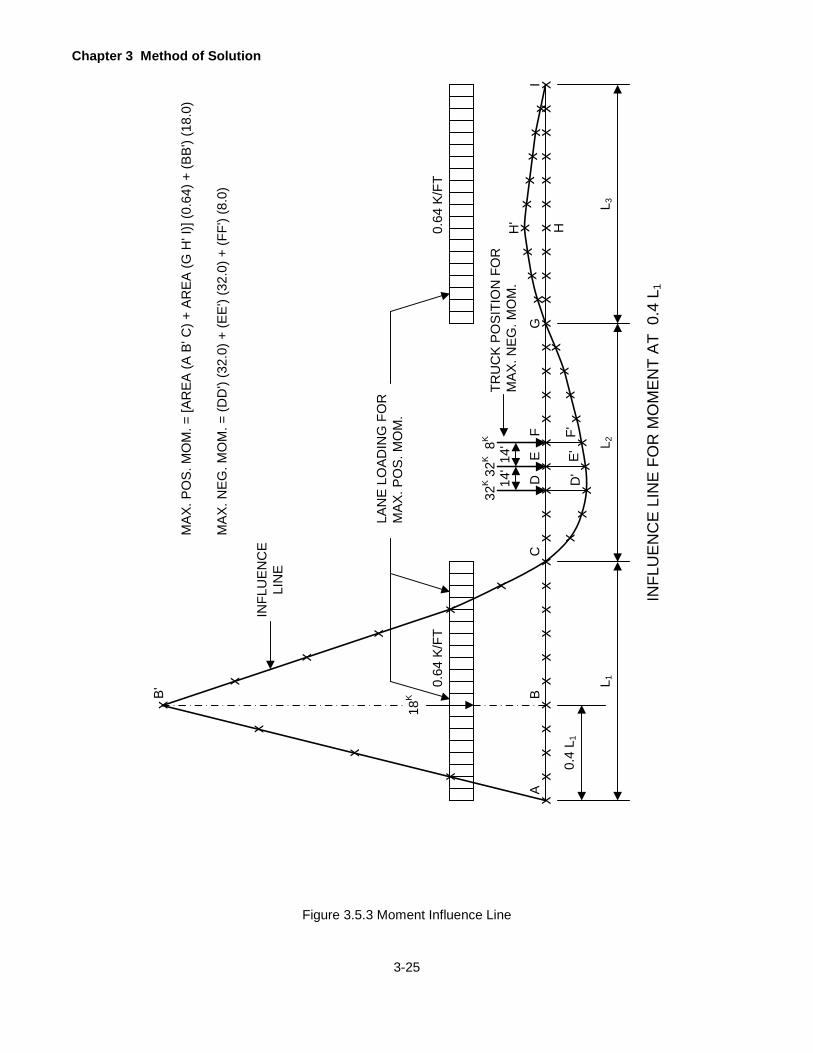
Chapter 3 Method of Solution
3-25
Figure 3.5.3 Moment Influence Line
INFL
UEN
CE
LIN
E FO
R M
OM
ENT
AT 0
.4 L
1
L 1L 2
L 3
xx
xx
xx
xx
xx
xx
xx
xx
xx
xx
xx
xx
xx
xx
xx
x0.
4 L 1
x
x
x
x
x
x
x
x
x
xx
xx
xx
xx
xx
xx
xx
xx
xx
18K
0.64
K/F
T0.
64 K
/FT
INFL
UEN
CE
LIN
E
MAX
. PO
S. M
OM
. = [A
REA
(A B
' C) +
AR
EA (G
H' I
)] (0
.64)
+ (B
B') (
18.0
)
MAX
. NEG
. MO
M. =
(DD
') (3
2.0)
+ (E
E') (
32.0
) + (F
F') (
8.0)
LAN
E LO
ADIN
G F
OR
MAX
. PO
S. M
OM
.
B'
AB
CD
EF
D'
E'F'
14'
14'
32K
32K
8KTR
UC
K PO
SITI
ON
FO
RM
AX. N
EG. M
OM
.
G
HH'
I
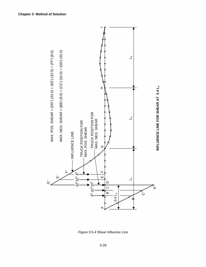
Chapter 3 Method of Solution
3-26
Figure 3.5.4 Shear Influence Line
INFL
UEN
CE
LIN
E FO
R S
HEA
R A
T 0
.4 L
1
L 1L 2
L 3
xx
xx
xx
xx
xx
xx
xx
xx
xx
xx
xx
xx
xx
xx
xx
x
0.4
L 1
x
x
xx
xx
xx
xx
xx
xx
xx
xx
xx
INFL
UE
NC
E L
INE
MA
X. P
OS
. SH
EA
R =
(DD
'') (3
2.0)
+ (E
E')
(32.
0) +
(FF'
) (8.
0)
AGTR
UC
K P
OS
ITIO
N F
OR
MA
X. N
EG
. SH
EA
RH
I
x
x
x
x
TRU
CK
PO
SIT
ION
FO
RM
AX
. PO
S. S
HE
AR
32K32
K8K
32K32
K8K F
ED
CB
B'
C'
D'
D''
E'
F'
MA
X. N
EG
. SH
EA
R =
(BB
') (8
.0) +
(CC
') (3
2.0)
+ (D
D')
(32.
0)

Chapter 3 Method of Solution
3-27
3.5.5 Live Load Distribution
The live load distribution factor is defined as a fraction (or multiple) of the axle load that is carried by the
member of a bridge. The live load distribution factors for moment, shear and deflections for a girder of the
multigirder bridge, a stringer of bridge types "GFS" and "TFS", an R. C. T-beam and an encased I-beam
are determined and entered by the user. The live load distribution factor for the main girder or truss is
computed by the program in accordance with the AASHTO Manual and the AASHTO Specifications as
explained below.
The distribution factor calculated for the main girder or truss is a function of the width, number and location
of traffic lanes, the distance between two wheels (gage distance), the minimum distance between two
passing vehicles (passing distance) and the center-to-center spacing of main girders or trusses. The
distribution factor is computed either based on the design traffic lanes (determined by the program in
accordance with AASHTO Specifications) or the loaded traffic lanes (as defined by the user). The live load
effect (moment, shear or axial force) used in calculating the Inventory and Operating rating based on design
lanes or loaded lanes is obtained by applying the appropriate distribution factor.
The distribution factor is computed as follows. The wheels are placed within each lane in accordance with
the AASHTO Manual such that the maximum reaction occurs at the left girder or truss centerline. The
reaction expressed as a fraction (or multiple) of the total number of lanes is the distribution factor. A
reduction in live load intensity is applied when more than one lanes are loaded. This reduction is applied
in accordance with the AASHTO Specifications when design lanes are considered and according to
percentage of live load for each lane (input value) when loaded lanes are considered. Figure 3.5.5 on page
3-28 shows the placement of lanes and the calculation of distribution factor based on design lanes and
loaded lanes.
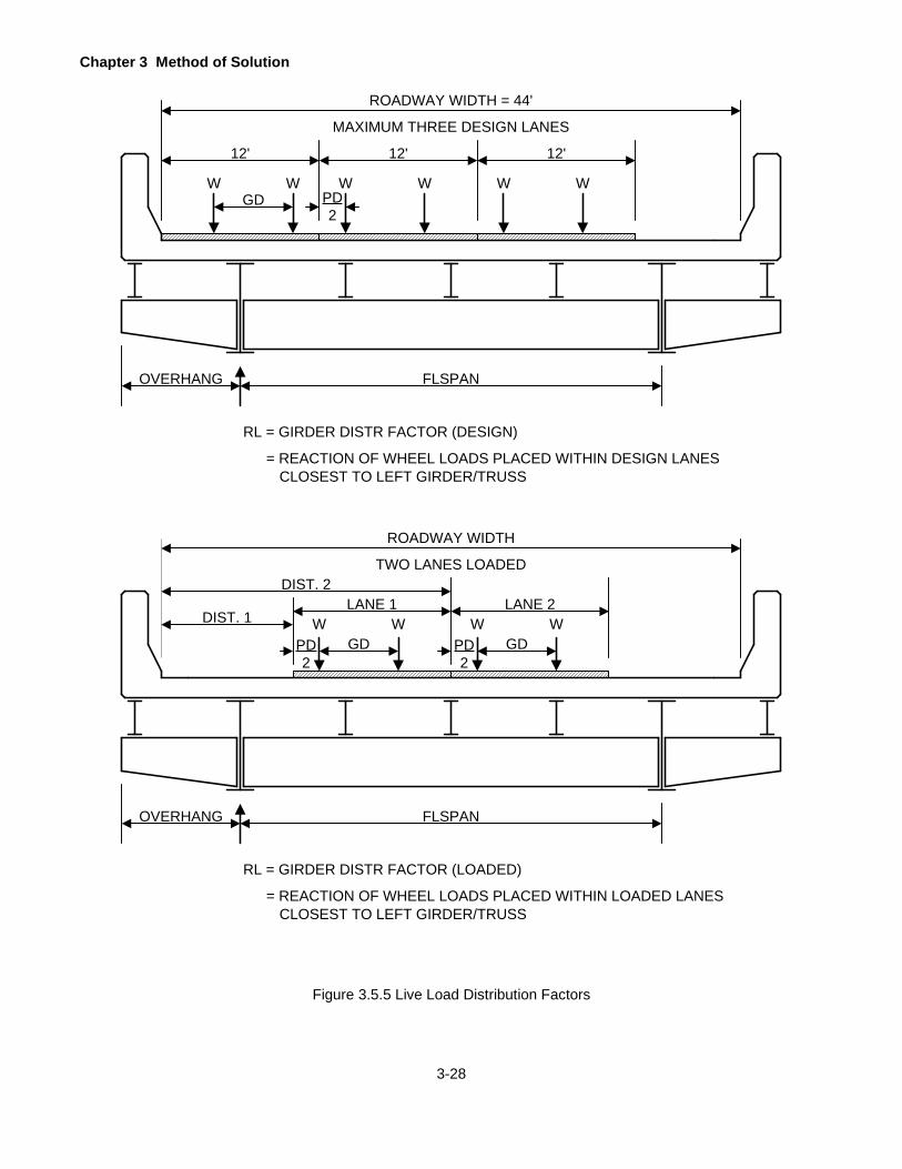
Chapter 3 Method of Solution
3-28
Figure 3.5.5 Live Load Distribution Factors
12' 12' 12'
ROADWAY WIDTH = 44'
W W W W W W
MAXIMUM THREE DESIGN LANES
GD PD2
OVERHANG FLSPAN
RL = GIRDER DISTR FACTOR (DESIGN)
= REACTION OF WHEEL LOADS PLACED WITHIN DESIGN LANESCLOSEST TO LEFT GIRDER/TRUSS
DIST. 1LANE 1 LANE 2
ROADWAY WIDTH
W W
TWO LANES LOADED
GDPD2
OVERHANG FLSPAN
RL = GIRDER DISTR FACTOR (LOADED)
= REACTION OF WHEEL LOADS PLACED WITHIN LOADED LANESCLOSEST TO LEFT GIRDER/TRUSS
DIST. 2
W WGDPD
2

Chapter 3 Method of Solution
3-29
3.5.6 Impact
The impact factors (I) are added to all live loads to account for the speed, vibration, and momentum from the vehicle traffic and are computed using the following formula given in the AASHTO Specifications.
125L50I+
= , I shall be less than or equal to 0.3
For computing the impact fraction I, the program uses the loaded length "L" in feet as described below.
For a continuous girder or stringer, the loaded length "L" is taken as follows:
1. For a positive reaction at an end support, the end span length is used.
2. For a negative reaction at an end support, the length of the adjacent loaded span is used.
3. For a positive reaction at an interior support, the average length of two adjacent spans is used.
4. For a negative reaction at an interior support, the average length of two nearest loaded spans is
used.
5. For a positive moment at an interior support, the average length of two nearest loaded spans is
used.
6. For a negative moment at an interior support, the average of two adjacent span lengths is used.
7. For a positive moment at any point within a span, the length of the span is used.
8. For a negative moment at any point within a span, the length of the loaded span is used. The span
with the largest area under the influence line is determined to be the loaded span.
9. For a shear, the length of the loaded portion of the span from the point under consideration to the
far reaction is used.
For a floorbeam, the loaded length “L” is taken as follows:
1. For a positive moment in the floorbeam, the center-to-center distance between the main girders or
trusses is used.
2. For a negative moment at any point in a cantilevered floorbeam, a length of zero is used to apply
the impact fraction of 0.3.
3. For a shear in the cantilever, a length of zero is used to apply the impact fraction of 0.3.
4. For a shear at any point between the main girders or trusses, the length of the loaded portion of
the floorbeam from the point under consideration to the far girder or truss is used.
For each member of the truss the loaded length "L" is taken as follows:
1. For the maximum compression in the top chord and the maximum tension in the bottom chord of a
continuous span truss, the length of the span is used where the member belongs.
2. For the maximum tension in the top chord and the maximum compression in the bottom chord of a
continuous span truss, the average length of two adjacent spans is used.
3. For the maximum tension in the bottom chord and the maximum compression in the top chord of a
simple span truss, the length of the span is used.
4. For the diagonals and vertical members, the length of the positive area of the influence line is used
for the maximum tension and the length of the negative area of the influence line is used for the
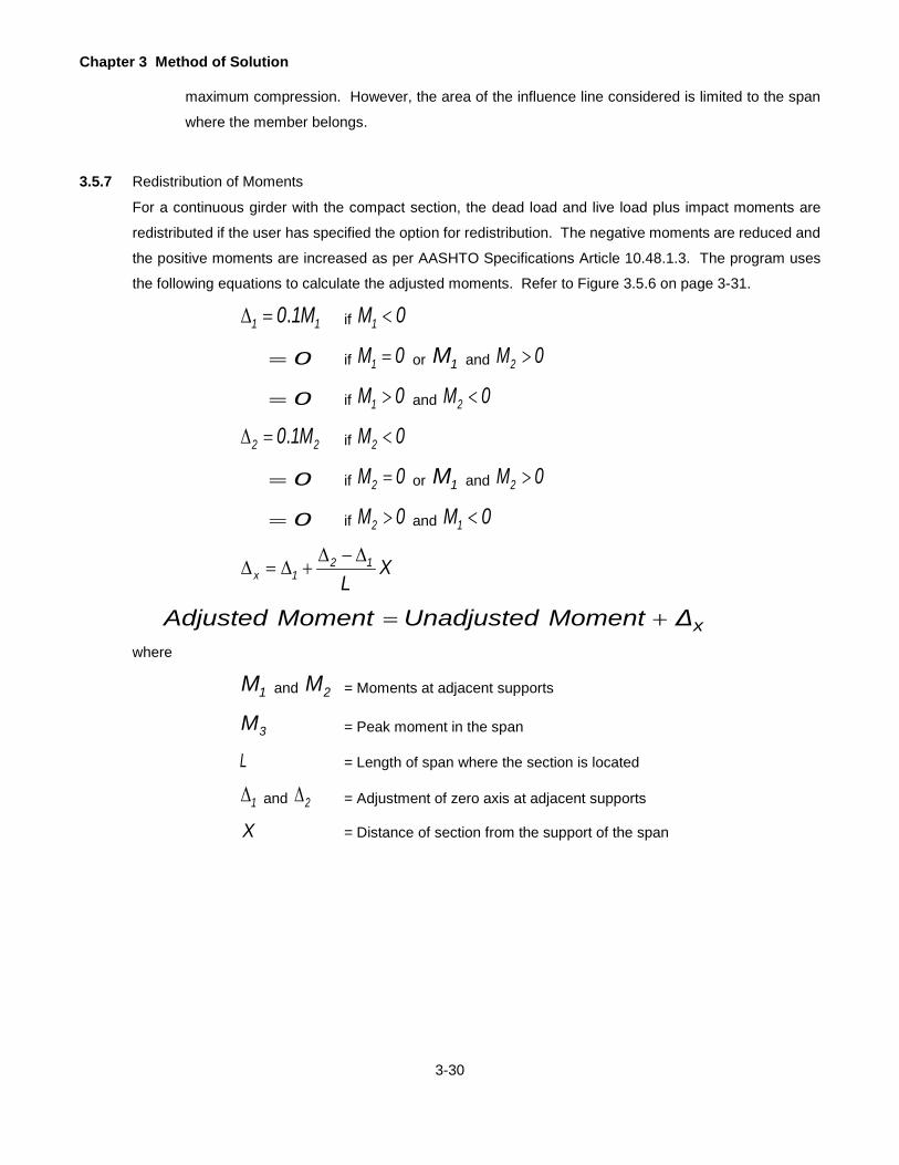
Chapter 3 Method of Solution
3-30
maximum compression. However, the area of the influence line considered is limited to the span
where the member belongs.
3.5.7 Redistribution of Moments
For a continuous girder with the compact section, the dead load and live load plus impact moments are
redistributed if the user has specified the option for redistribution. The negative moments are reduced and
the positive moments are increased as per AASHTO Specifications Article 10.48.1.3. The program uses
the following equations to calculate the adjusted moments. Refer to Figure 3.5.6 on page 3-31.
11 M10.=∆ if 0M1 <
0= if 0M1 = or 1M and 0M2 >
0= if 0M1 > and 0M2 <
22 M10.=∆ if 0M2 <
0= if 0M2 = or 1M and 0M2 >
0= if 0M2 > and 0M1 <
XL
121x
∆−∆+∆=∆
xΔMomentUnadjustedMomentAdjusted +=where
1M and 2M = Moments at adjacent supports
3M = Peak moment in the span
L = Length of span where the section is located
1∆ and 2∆ = Adjustment of zero axis at adjacent supports
X = Distance of section from the support of the span
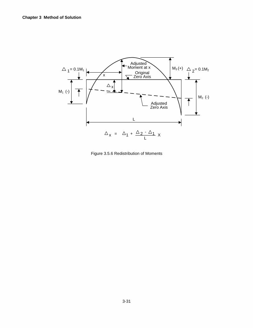
Chapter 3 Method of Solution
3-31
Figure 3.5.6 Redistribution of Moments
L
Adjusted Zero Axis
= +1 2 - 1 XL
x
Adjusted Moment at x
OriginalZero Axis
M3 (+)
M2 (-)
= 0.1M11
M1 (-)
= 0.1M22
x
x

Chapter 3 Method of Solution
3-32
SECTION CAPACITY
The Allowable Stress Method utilizes the section capacity to calculate the rating. Section capacities are based on
allowable stresses as specified in the AASHTO Manual.
3.6.1 Allowable Stresses
The program uses the following allowable stresses to calculate the moment capacity of a flexural member
in accordance with the AASHTO Manual Articles 6.6.2.1, 6.6.2.3 and 6.6.2.4 with the exception of partially
supported or unsupported compression flange. The allowable stresses are calculated from the Fy and fc'
values as specified by the user.
Inventory Operating
Steel (Flexure tension and fully supported compression) 0.55 Fy 0.55 Fy
Steel (Flexure partially supported compression) Fb 1.36 Fb
Steel (Shear) 0.33 Fy 0.45 Fy
Concrete (Compression due to bending) fcir fcor
fc’ Unknown (Left Blank) 950 psi 1300 psi
fc’ Known (Entered) 0.40 fc’ 0.55 fc’
Reinforcing Steel: fsir fsor Fy
Grade Unknown 18,000 psi 25,000 psi 33,000 psi
Structural Grade 18,000 psi 25,000 psi 36,000 psi
Grade 40 20,000 psi 28,000 psi 40,000 psi
Grade 50 20,000 psi 32,500 psi 50,000 psi
Grade 60 24,000 psi 36,000 psi 60,000 psi
3.6.2 Flexural Steel Member
1. The allowable stress in a compression flange supported laterally its full length by embedment in
concrete is calculated per AASHTO Specifications Table 10.32.1 A (equal to 0.55 Fy for Inventory
Rating and 0.75 Fy for Operating Rating).
2. The allowable compression in partially supported or unsupported compression flange, defined as Fb
under ALLOWABLE STRESSES, is calculated according to the year of specifications to be used (input)
as follows:
S821MF U
b .= where MU is calculated per Equation (10-102), and
S is section modulus of compression flange (for 1989 Specs)

Chapter 3 Method of Solution
3-33
bb FF = given in Table 10.32.1A (1990 Interim) or
82.1FF b
b = given in D10.48.4.1 (DM4), whichever is smaller (for 1990 Specs)
When the 1989 Specifications are used, the program does not use the equation given for Fb in Table
10.32.1A (1989) because of a slight inconsistency in defining the term b used in Table 10.32.1A and
the term b' used in Equation (10-102). The program takes a conservative approach by using the Load
Factor equation and applying a factor of safety of 1.82 to get an Allowable Stress equation.
3. The moment capacity of the steel section for Inventory Rating, MCIR, is calculated by:
SfM sirCIR = where, fsir = 0.55 Fy or Fb
4. The moment capacity of the steel section for Operating Rating, MCOR, is calculated by:
SfM sorCOR = where, fsir = 0.75 Fy or 1.36 Fb
5. The shear capacity of the steel section for Inventory Rating, VCIR, is calculated by:
virwCIR FDtV = where, Fvir = FV
as calculated by AASHTO Specifications 10.34.4.1 for unstiffened web
or as calculated by AASHTO Specifications 10.34.4.2 for stiffened web
6. The shear capacity of the steel section for Operating Rating, VCOR, is calculated by:
vorwCOR FdtV = where, Fvor = 1.36 Fvir
3.6.3 Flexural Concrete Member
1. The moment capacity of the concrete section for Inventory Rating, MCIR, is calculated by:
=CIRM least of CcirSf and SsirSf2. The moment capacity of the concrete section for Operating Rating, MCOR, is calculated by:
=CORM least of CcorSf and SsorSf3. The shear capacity of the concrete section for Inventory Rating, VCIR, is calculated by:
'. ccir f950v = for 1974 and later specifications
'. cf030= for 1973 and earlier specifications, but not greater than 90 psi
sirvbsir fAV αsin= but not greater than dbf51 wc '. for slab bridge where bw = 12.0
sirvbsirvs fA
sdfA αsin+= but not greater than dbf04 wc '. for T-beam bridge
sirwcirCIR VdbvV +=
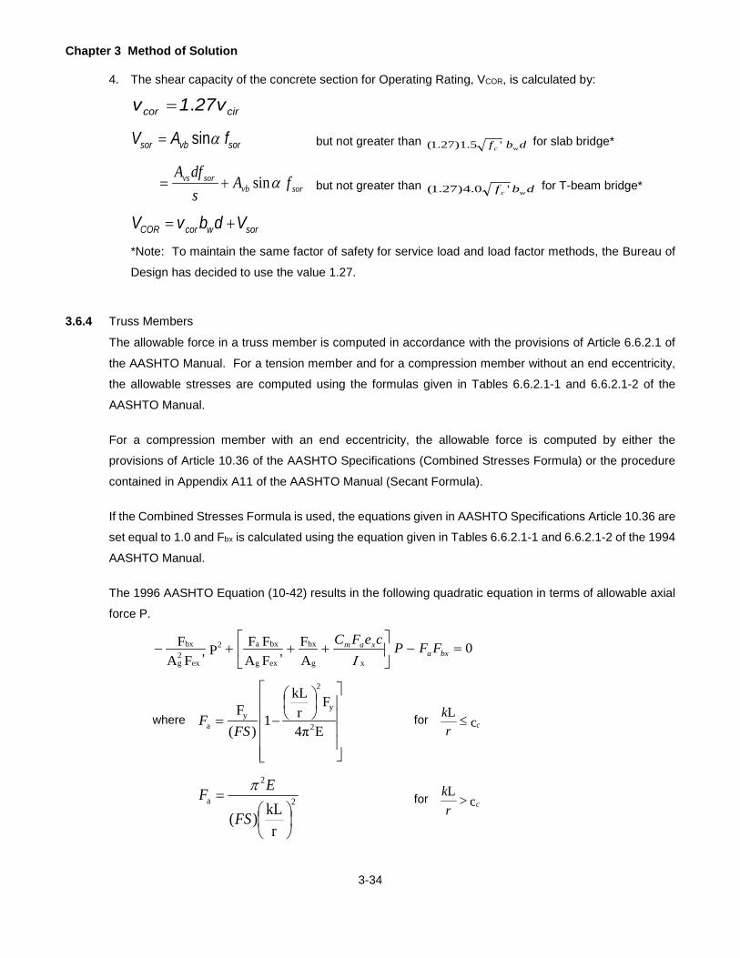
Chapter 3 Method of Solution
3-34
4. The shear capacity of the concrete section for Operating Rating, VCOR, is calculated by:
circor v271v .=
sorvbsor fAV αsin= but not greater than dbf wc '5.1)27.1( for slab bridge*
sorvbsorvs fA
sdfA
αsin+= but not greater than dbf wc '0.4)27.1( for T-beam bridge*
sorwcorCOR VdbvV +=
*Note: To maintain the same factor of safety for service load and load factor methods, the Bureau of
Design has decided to use the value 1.27.
3.6.4 Truss Members
The allowable force in a truss member is computed in accordance with the provisions of Article 6.6.2.1 of
the AASHTO Manual. For a tension member and for a compression member without an end eccentricity,
the allowable stresses are computed using the formulas given in Tables 6.6.2.1-1 and 6.6.2.1-2 of the
AASHTO Manual.
For a compression member with an end eccentricity, the allowable force is computed by either the
provisions of Article 10.36 of the AASHTO Specifications (Combined Stresses Formula) or the procedure
contained in Appendix A11 of the AASHTO Manual (Secant Formula).
If the Combined Stresses Formula is used, the equations given in AASHTO Specifications Article 10.36 are
set equal to 1.0 and Fbx is calculated using the equation given in Tables 6.6.2.1-1 and 6.6.2.1-2 of the 1994
AASHTO Manual.
The 1996 AASHTO Equation (10-42) results in the following quadratic equation in terms of allowable axial
force P.
0AF
'FAFFP'FA
Fxg
bx
exg
bxa2
ex2g
bx =−
+++− bxa
xam FFPceFCΙ
where
−=E4π
Fr
kL
1)(
F2
y
2
ya FS
F for cL
crk
≤
2
2
a
rkL)(
=FS
EF πfor c
Lcr
k>
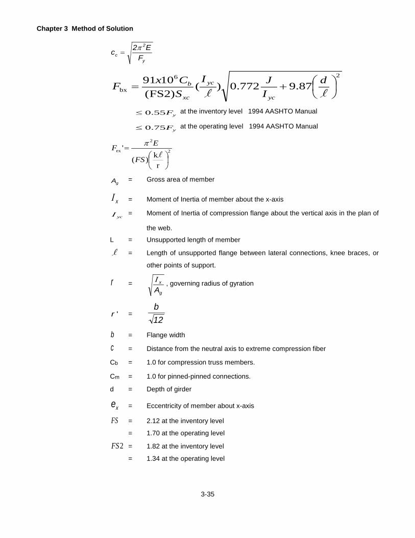
Chapter 3 Method of Solution
3-35
y
2
c FE2c π
=
26
bx 87.9772.0)()FS2(
1091
+=
lld
IJI
SCxF
yc
yc
xc
b
yF55.0≤ at the inventory level 1994 AASHTO Manual
yF75.0≤ at the operating level 1994 AASHTO Manual
2
2
ex
rk)(
'
=lFS
EF π
gA = Gross area of member
xΙ = Moment of Inertia of member about the x-axis
ycΙ = Moment of Inertia of compression flange about the vertical axis in the plan of
the web.
L = Unsupported length of member
l = Length of unsupported flange between lateral connections, knee braces, or
other points of support.
r =g
x
AΙ , governing radius of gyration
'r = 12b
b = Flange width
c = Distance from the neutral axis to extreme compression fiber
Cb = 1.0 for compression truss members.
Cm = 1.0 for pinned-pinned connections.
d = Depth of girder
xe = Eccentricity of member about x-axis
FS = 2.12 at the inventory level
= 1.70 at the operating level
2FS = 1.82 at the inventory level
= 1.34 at the operating level

Chapter 3 Method of Solution
3-36
J = [(bt3)c + (bt3)t + Dtw3]/3, where b and t represent the flange width and thickness
of the compression and tension flange, D is the web depth, and tw is the web
Thickness.
k = 0.875 for pinned ends
= 0.75 for riveted ends
xcS = Section modulus with respect to the compression flange.
P is taken as the smaller of the roots given by the above quadratic equation and the following 1996 AASHTO
Equation (10-43).
bxx
x
yg Fce
FA47201
1P
Ι+
=
.
If the procedure contained in Appendix A11 of the AASHTO Manual is used, the program assumes that the
eccentricity at both ends of the member is the same, and thus the other formulas of that article are
considered not applicable.

Chapter 3 Method of Solution
3-37
MAXIMUM STRENGTH
The ratings calculated by the Load Factor Method are based on the following load-strength relationship.
[ ])ILL)(RF(2DL1DL3.1StrengthMaximum +++=where DL1, DL2, and LL+I are effects due to non-composite dead load, composite dead load and live load plus
impact and RF is the rating factor.
The program uses the logic given in the flow chart shown in Figure 3.7.2 on page 3-41 to calculate RF. Please note
that the beta factor for live load plus impact used for moments and shears to calculate the rating factor in the above
relationship and in the flowchart is 1.0 and RF is the Operating Rating Factor.
The Maximum Strengths of a section are flexural strength, shear strength, strengths based on overload provisions
and moment-shear interaction. The program calculates the following strengths.
3.7.1 Flexural Strength of Steel Member
The Flexural Strength, MU, is calculated for various types of sections depending upon whether the section
is compact, braced non-compact or unbraced non-compact as defined in the AASHTO Specifications. The
program uses the logic given in the flow chart shown in Figure 3.7.2 on page 3-41 to determine the type of
section. The beta factor for live load plus impact used for moments and shears in checking compactness,
ductility and moment-shear interaction equations shown in the flow charts is taken as 1.67. Refer to the
AASHTO Specifications for symbols and equations used in the flow chart. The program calculates the
flexural strengths based on the yielding of tension flange, compression flange and top of concrete slab or
tension reinforcement and uses appropriate strength to determine the critical rating factor.
The flexural strength of box-shaped steel cross girder/floorbeam is calculated assuming it is non-composite and non-compact. The flexural resistance prescribed in AASHTO LRFD Article 6.12.2.2.2 has been considered for these members.
3.7.1.1 Compact Section
The Flexural Strength, MU, of a compact section is taken as the full plastic moment of the section, Mp, and
is calculated in the following manner. First the location of the plastic neutral axis is assumed at the mid
height of the steel section. Assuming all fibers stressed to the yield stress, forces in various elements of the
section are calculated by multiplying the area and yield stress of the element. The sum of forces in elements
in compression is compared with the sum of forces in elements in tension. If these forces are not equal, a
new position of the neutral axis is assumed and the above steps are repeated until both forces become
equal. The maximum strength of the section is found by taking the first moment of all forces about the
neutral axis, taking all forces and moment arms as positive quantities. Refer to Figure 3.7.1 on page 3-40.

Chapter 3 Method of Solution
3-38
Program assumes bridges with variable depth web, built up section, or longitudinal stiffener as non-compact section.
Non-composite sections meeting compact section requirements (1996 AASHTO Specifications Article 10.48.1.1 (a) (b) (c)) shall be computed as compact sections. Composite sections meeting compact section requirements (1996 AASHTO Specifications Article 10.48.1.1 (b) (c)) and Fy less than 50,000 psi shall be computed as compact sections.
For checking the ductility requirements of a compact composite section in positive moment region as per
Eqn (10-129a) given in 1996 AASHTO Specifications Article 10.50.1.1.2, the value of β used is 0.9 for Fy ≥
36,000 psi, and it is 0.7 for 36,000 < Fy ≤ 50,000 psi.
The program also assumes that the plastic moment capacity can only be used for the calculation of ratings
if all sections over the entire length of the member (whether composite or non-composite) qualify as
compact sections.
3.7.1.2 Braced Non-compact Section
The Flexural Strength, Mu, of a member not meeting compact section requirements (1996 AASHTO Specifications Article 10.48.1.1) but meeting the AAHSTO braced non-compact section requirements (1996 AASHTO Specifications Article 10.48.2.1) shall be computed as Fy*S.
3.7.1.3 Unbraced Non-compact Section
The Flexural Strength, MU, of a member controlled by compression in a partially supported or unsupported
flange is calculated per 1996 AASHTO Specifications Article 10.48.4.1. For this, the unbraced length is
taken as the distance between bracings. If the 1989 or earlier specifications are used, the program
computes MU per equation 10-102 given in AASHTO Specifications (1989) Article 10.48.4.1. For this, the
unbraced length is taken as the minimum of the distance between bracings or the distance between the
points of dead load contraflexure to the farthest bracing. The program also has the option to use the
equations given in Article D10.48.4.1 of 1988 DM-4. For this, the unbraced length is taken as a minimum
of the distance between bracings or the distance between the points of dead load contraflexure to the
farthest bracing.
3.7.2 Shear Strength of Steel Member
Based on user input of stiffened or unstiffened condition, the Shear Strength, VU, is calculated for various
points along the length of the steel member per 1996 AASHTO Specifications Article 10.48.8 Shear.
The program uses the logic given in the flow chart shown in Figure 3.7.2 on page 3-41 to determine the
type of section and the shear strength.

Chapter 3 Method of Solution
3-39
Box-shaped cross girders/floorbeams resist a small amount of shear due to torsion. To accommodate torsion in these members, the per web shear strength of the box section is multiplied by 0.9 factor.
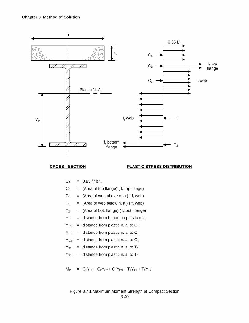
Chapter 3 Method of Solution
3-40 Figure 3.7.1 Maximum Moment Strength of Compact Section
ts
b
Plastic N. A.
YP
CROSS - SECTION PLASTIC STRESS DISTRIBUTION
0.85 fc'
C1
C2
C3
T1
T2fy bottom
flange
fy web
fy web
fy topflange
C1
C2
C3
T1
T2
YP
YC1
YC2
YC3
YT1
YT2
MP
= 0.85 fc' b ts= (Area of top flange) ( fy top flange)
= (Area of web above n. a.) ( fy web)
= (Area of web below n. a.) ( fy web)
= (Area of bot. flange) ( fy bot. flange)
= distance from bottom to plastic n. a.
= distance from plastic n. a. to C1
= distance from plastic n. a. to C2
= distance from plastic n. a. to C3
= distance from plastic n. a. to T1
= distance from plastic n. a. to T2
= C1YC1 + C2YC2 + C3YC3 + T1YT1 + T2YT2

Chapter 3 Method of Solution
3-41
ANALYZE SECTIONCOMPUTE Dcp
COMPOSITE
M > 0
Yes
cpD < D2
Yes
COMPOSITE M > 0 Fy > 50
pDD'
> 5
Yes Yes
No
2Dt
> 19230F
cp
w y
Yes
( )b't
>.75 b't max
Yes cp
w
2Dt
>.75 19230F y
No
A
No
Yescp
w
2Dt
+ 9.35 b't
> 33650F y
No
Yes
B
cpD = D2
Yes
Yes
No
Yes
No Yes
No
MU = MP
Dp < D'Yes
No
M 5M 0.85M4
0.85M M4
DD'U
P Y Y P p=−
+−
No
VariableDepth WebNo Yes
LongitudinallyStiffened No
Built-UpSection
Yes Yes
No
POSSIBLE FLANGE BUCKLING
CONSTRUCTABILITY PROBLEM 1.3
2200tb'
DL1f>
No
No Yes
F2055
tb'
y
>
No
No
No
Equ. 10-122
Equ. 10-93
Equ. 10-129b
Equ. 10-129c
Equ. 10-129
Equ. 10-95Equ. 10-94
Equ. 10-129a
Figure 3.7.2 Load Factor Rating Flow Chart
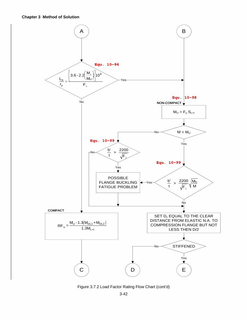
Chapter 3 Method of Solution
3-42
A B
Lr
3.6 - 2.2 MM
10
Fb
y
U
61
y
>
No
Yes
MU = Fy SL+I
NON-COMPACT
COMPACT
( )MRF =
M -1.3 M +M1.3M
U DL1 DL2
L+I
M < MUNo
b't
> 2200F y
No
POSSIBLEFLANGE BUCKLINGFATIGUE PROBLEM
Yes
b't
> 2200F
MM
y
U
Yes
No
SET Dc EQUAL TO THE CLEAR DISTANCE FROM ELASTIC N.A. TO COMPRESSION FLANGE BUT NOT
LESS THEN D/2
STIFFENED
Yes
E
No
DC
Yes
Equ. 10-96
Equ. 10-98
Equ. 10-99
Equ. 10-99
Figure 3.7.2 Load Factor Rating Flow Chart (cont’d)

Chapter 3 Method of Solution
3-43
C D E
F
c
w y
Dt
> 15400F
Yes
POSSIBLEWEB BUCKLING
FATIGUE PROBLEM
TRANSVERSEONLY
No
Yes
c
w y
Dt
> 36500F
Yes
Noc
w y
D
t> 18250
F
No
Yes
dF A20,000,000 >L
y
fb
Yes
No
DETERMINE MUPER 1996 AASHTO 10.48.4.1
1
2
M
M< 0.7 No
Yes
1.2MU < FySL+I Yes
MU = 1.2MU
No
MU = FySL+I
MUT = FySL+I
MUD = f 'cSconcn
UNBRACED
BRACED
No
Equ. 10-100
Equ. 10-104
Equ. 10-120
Equ. 10-101
Figure 3.7.2 Load Factor Rating Flow Chart (cont’d)
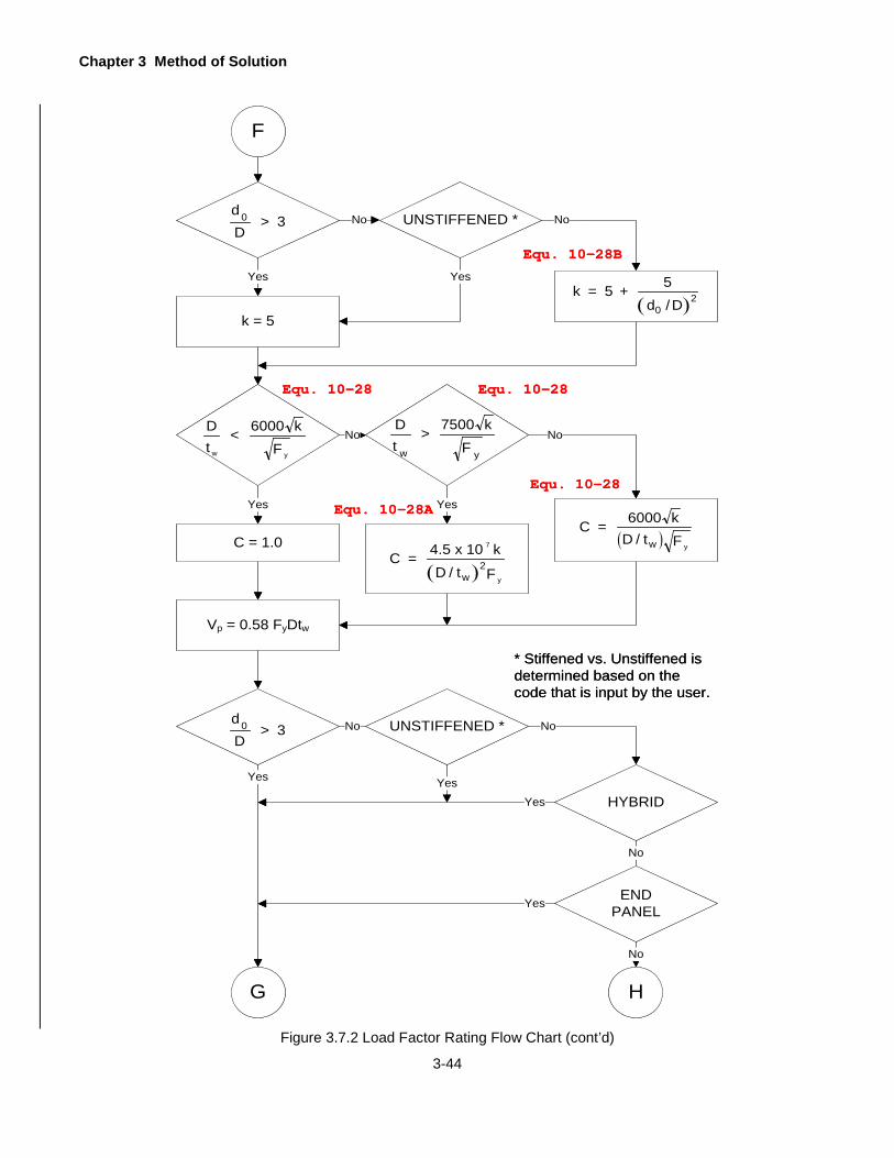
Chapter 3 Method of Solution
3-44
F
0dD
> 3 No UNSTIFFENED *
Yes
Dt
< 6000 kFw y
Dt
> 7500 kFw y
Yes
C = 1.0
No
Yes
( )C = 4.5 x 10 k
D / t F
7
y
2w
( )C = 6000 k
D / t Fw y
Vp = 0.58 FyDtw
0dD
> 3 No
Yes
G H
UNSTIFFENED *
Yes
HYBRID
No
No
Yes
No
k = 5( )
k = 5 + 5d /D 2
0
No
Yes
ENDPANELYes
No
* Stiffened vs. Unstiffened isdetermined based on the code that is input by the user.
Equ. 10-28B
Equ. 10-28 Equ. 10-28
Equ. 10-28A
Equ. 10-28
Figure 3.7.2 Load Factor Rating Flow Chart (cont’d)

Chapter 3 Method of Solution
3-45
G H
( )( )
V = V C+0.87 1- C
1+ d /DU P
02
VU = CVP
| ML+I | > 0 Yes
NoCOMPACTYes
No
RF =M -1.3S M
SMS
1.3MMC
U L+IDL1
DL1
DL2
DL2
L+I
+
RF =M -1.3S M
SMS
1.3MMT
UT L+IDL1
DL1
DL2
DL2
L+I
+
RF =M -1.3S M
S1.3MMD
UD CDL2
DL2
L+I
RFM = MINIMUM OF RFMC,RFMT AND
RFMD
MU = MU CORRESPONDING RFM
I
Equ. 10-27
Figure 3.7.2 Load Factor Rating Flow Chart (cont’d)

Chapter 3 Method of Solution
3-46
Figure 3.7.2 Load Factor Rating Flow Chart (cont’d)
I
MO = 0.8FySL+I
COMPOSITE Yes
MO = 0.95FySL+I
RF =M -S M
S+ M
SMO
O L+IDL1
DL1
DL2
DL2
L+I
( )RF =
V -1.3 V + V1.3VV
U DL1 DL2
L+I
STIFFENED *No
RF = MIN(RFM,RFV)
V=1.3[VDL1+VDL2+RF(VL+I)]
M=1.3[MDL1+MDL2+RF(ML+I)]
J K
No
Yes
* Stiffened vs. Unstiffened isdetermined based on the code that is input by the user.

Chapter 3 Method of Solution
3-47
Figure 3.7.2 Load Factor Rating Flow Chart (cont’d)
J K
VM
< 0.6VM
U
UYes
No
VM
> V0.75M
U
UYes
No
( ) ( )
( )( ) ( )( )[ ]RF =1.375M V -1.3 V S M
S+ M
S+ 0.625 V + V M
1.3 M V + 0.625 V MMV
U U U L+IDL1
DL1
DL2
DL2DL1 DL2 U
L+I U L+I U
CHECK SHEAR & MOMENT/SHEAR RATINGS FOR ALL COMBINATIONS OF POSITIVE & NEGATIVE
MOMENTS AND SHEARS
CRITICAL LOAD FACTOR RATING IS MINIMUM OF RFM, RFS, RFV & RFMV
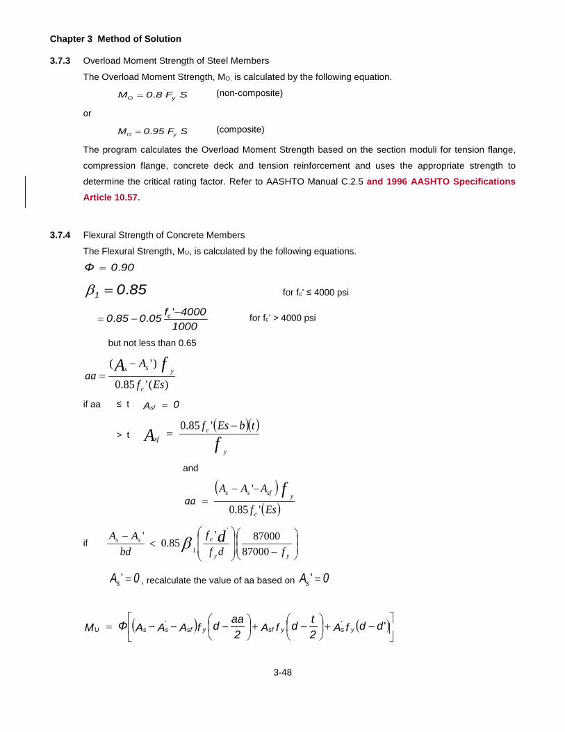
Chapter 3 Method of Solution
3-48
3.7.3 Overload Moment Strength of Steel Members
The Overload Moment Strength, MO, is calculated by the following equation.
SF80M yO .= (non-composite)
or
SF950M yO .= (composite)
The program calculates the Overload Moment Strength based on the section moduli for tension flange,
compression flange, concrete deck and tension reinforcement and uses the appropriate strength to
determine the critical rating factor. Refer to AASHTO Manual C.2.5 and 1996 AASHTO Specifications Article 10.57.
3.7.4 Flexural Strength of Concrete Members
The Flexural Strength, MU, is calculated by the following equations.
900Φ .=
8501 .=β for fc’ ≤ 4000 psi
10004000f050850 c −
−='.. for fc’ > 4000 psi
but not less than 0.65
)('85.0
)'(
Esf
Aaa
c
yss fA −=
if aa ≤ t 0Asf =
> t ( )( )fA
y
csf
tbEsf −=
'85.0
and
( )( )Esf
AAAaa
c
ysfss f'85.0
'−−=
if
−
<
−
yy
css
fdff
bdAA d
8700087000'
85.0'
'
1β
0As =' , recalculate the value of aa based on 0As ='
( ) ( )
−+
−+
−−−= ''' ddfA2
tdfA2aadfAAAΦM ysysfysfssU

Chapter 3 Method of Solution
3-49
3.7.5 Shear Strength of Concrete Members
The Shear Strength, VU, is calculated by the following equation.
( )SCU VVΦV += where 85.0Φ =
dbf2V cC '=
αsinfAV yvbS = but not greater than dbf3 c ' (for a slab bridge)
αsinfAsdfA
V yvbyvs
S += but not greater than dbf8 c ' (for a T-beam bridge)
where s = stirrup spacing
3.7.6 Stresses
Extreme fiber stresses in flexural members (girder, stringer, floorbeam and R.C. beam) are calculated by
the following formulas.
SMf
1DL
1DL1DL =
SMf
2DL
2DL2DL =
SMf
ILL
ILLILL
+
++ =
These stresses are computed at the top of steel, bottom of steel, top of slab and center of gravity of slab
reinforcement.
The shear stress is computed by the following formula if shear is carried by the web portion of the section.
dtVvw
=
3.7.7 Limiting Bending Stress
When the shear stress is higher than 0.6*Fv, the limiting bending stress of steel beams subjected to simultaneous action of shear and bending moment shall be 0.754*FY – 0.34(fv/Fv)Fy, given in 1996 AASHTO 10.34.4.4.
fv is the average unit shear stress at the section Fv is the value from 1996 AASHTO Equation 10-27.
3.7.8 Shear Strength of Encased I-beam
When calculating the shear strength, an encased I-beam is considered as a stiffened composite steel
section. As seen in the Load Factor Rating Flow Chart shown in Figure 3.7.2 on page 3-41, there is no
difference between composite and non-composite sections when calculating the shear strength.
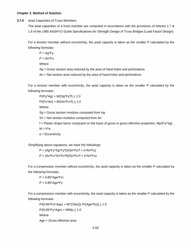
Chapter 3 Method of Solution
3-50
3.7.9 Axial Capacities of Truss Members
The axial capacities of a truss member are computed in accordance with the provisions of Articles 1.7 &
1.8 of the 1985 AASHTO Guide Specifications for Strength Design of Truss Bridges (Load Factor Design).
For a tension member without eccentricity, the axial capacity is taken as the smaller P calculated by the
following formulas:
P = Ag*Fy
P = An*Fu
Where
Ag = Gross section area reduced by the area of hand holes and perforations
An = Net section area reduced by the area of hand holes and perforations
For a tension member with eccentricity, the axial capacity is taken as the smaller P calculated by the
following formulas:
P/(Fy*Ag) + M/(Sg*Fy*f) < 1.0
P/(Fu*An) + M/(Sn*Fu*f) < 1.0
Where
Sg = Gross section modulus computed from Ag
Sn = Net section modulus computed from An
f = Plastic shape factor computed on the basis of gross or gross effective properties, Mp/(Fy*Sg)
M = P*e
e = Eccentricity
Simplifying above equations, we have the followings:
P = (Ag*Fy*Sg*Fy*f)/(Sn*Fy*f + e*An*Fy)
P = (An*Fu*Sn*Fu*f)/(Sn*Fu*f + e*An*Fu)
For a compression member without eccentricity, the axial capacity is taken as the smaller P calculated by
the following formulas:
P = 0.85*Age*Fcr
P = 0.85*Age*Fy
For a compression member with eccentricity, the axial capacity is taken as the smaller P calculated by the
following formulas:
P/(0.85*Fcr*Age) + M*C/Mu/[1-P/(Age*Fe)] < 1.0
P/(0.85*Fy*Age) + M/Mp < 1.0
Where
Age = Gross effective area

Chapter 3 Method of Solution
3-51
Fcr = Critical load per AASHTO Article 10.54.1.1 with a suitable effective length factor, K
C = Equivalent moment factor taken as 0.85 or 1.00 as appropriate
Fe = (0.85)(Pi*Pi)(E)/(KL/r)^2, Pi = 3.1415926583
Mp = Fy*f*Sge
Sge = Section modulus reduced for access holes, if any.
Mu = Maximum bending strength, reduced for lateral buckling as indicated herein.
M = P*e
e = Eccentricity
Simplifying above equations, we have the followings:
-Mu*P^2 + P*[Mu*Age*Fe + 0.85*e*C*Age*Fe*Age*Fcr + 0.85*Mu*Age*Fcr] -
0.85*Age*Fcr*Mu*Age*Fe < 0.0, P is taken the smaller of the root.
P = 0.85*Mp*Age*Fy/(Mp+0.85*Age*Fy*e)
The bending strength of truss member, Mu, shall be calculated using the equations given below:
For box-shaped members (SHAPE = 1):
−= ∑
IyEAtsFySgeL
FySgeMu)/(
0641.01
Where:
A = Area enclosed within centerlines of plates of box members
s/t = Length of a side divided by its thickness
Iy = Moment of inertia about the axis perpendicular to the bending axis.
L = Length of a member
Sge = Gross effective section modulus about bending axis]
For H-shaped members bent about their minor axis (SHAPE = 2):
Mu = 1.5*Fy*Sge
For H-shaped members, and members with channel flanges and a web plate, bent about their major axis
(SHAPE = 3):
If σcr < 0.5*Fy, Mu = σcr*Sge
If σcr > 0.5*Fy, Mu = Fy*Sge*[1-Fy/(4*σcr)]

Chapter 3 Method of Solution
3-52
4
2224
2
2
cr )(4)(1
KLEIyh
KLEIyGJ
Sge
ππσ +=
Where:
J = St. Venant torsional constant, approximately summation of b*t^3/3
h = Depth of web plate plus flange thickness
G = Shear modulus.
K = Effective length factor for column buckling about weak axis
Iy = Moment of inertia about the axis perpendicular to the bending axis
σcr = Critical elastic lateral-torsional buckling stress

Chapter 3 Method of Solution
3-53
LIVE LOAD RATINGS
The program calculates the flexural and shear ratings based on both the Allowable Stress Method and the Load
Factor Method. The rating is calculated as a factor that is a ratio of the allowable live load to the actual live load.
The rating of a bridge is then obtained by multiplying the gross weight of the live load by the minimum rating factor.
The rating factors for the ML80 and TK527 loadings are calculated based on the axle loads shown in Figure 2.4.1
on page 2-11 that include a 3% scale tolerance allowed by the vehicle code. The ratings in tons for the ML80 and
TK527 loadings do not include the 3% scale tolerance allowed by the vehicle code.
Rating factors are calculated for the Inventory Rating and the Operating Rating. For ratings, members are divided
into three types: flexural steel members (girder, stringer, floorbeam, encased I-beam, gusset plate for truss),
flexural concrete members (R.C. T -beam, R.C. Slab), and truss members (axial force only).
3.8.1 Flexural Steel Members
Based on the moments, shears, capacities, and strengths calculated as explained earlier, the program
computes the following rating factors based on the Allowable Stress and Load Factor Methods.
3.8.1.1 Allowable Stress Method
Inventory Rating
MSM
SMSM
IRILL
2DL
2DL
1DL
1DLILLCIR
1+
+
+−
=
VVVVIR
ILL
2DL1DLCIR2
+
−−=
+
++
+−
=+
+
+
FF
tDV340
SM
FF
tDV
tDV340
SM
SMF7540
IR
V
y
w
ILL
ILL
ILL
V
y
w
2DL
w
1DL
2DL
2DL
1DL
1DLy
3
.
..
Fv is the value from 1996 AASHTO Equation 10-26.
321 IRandIRIRofsmallerIR ,=
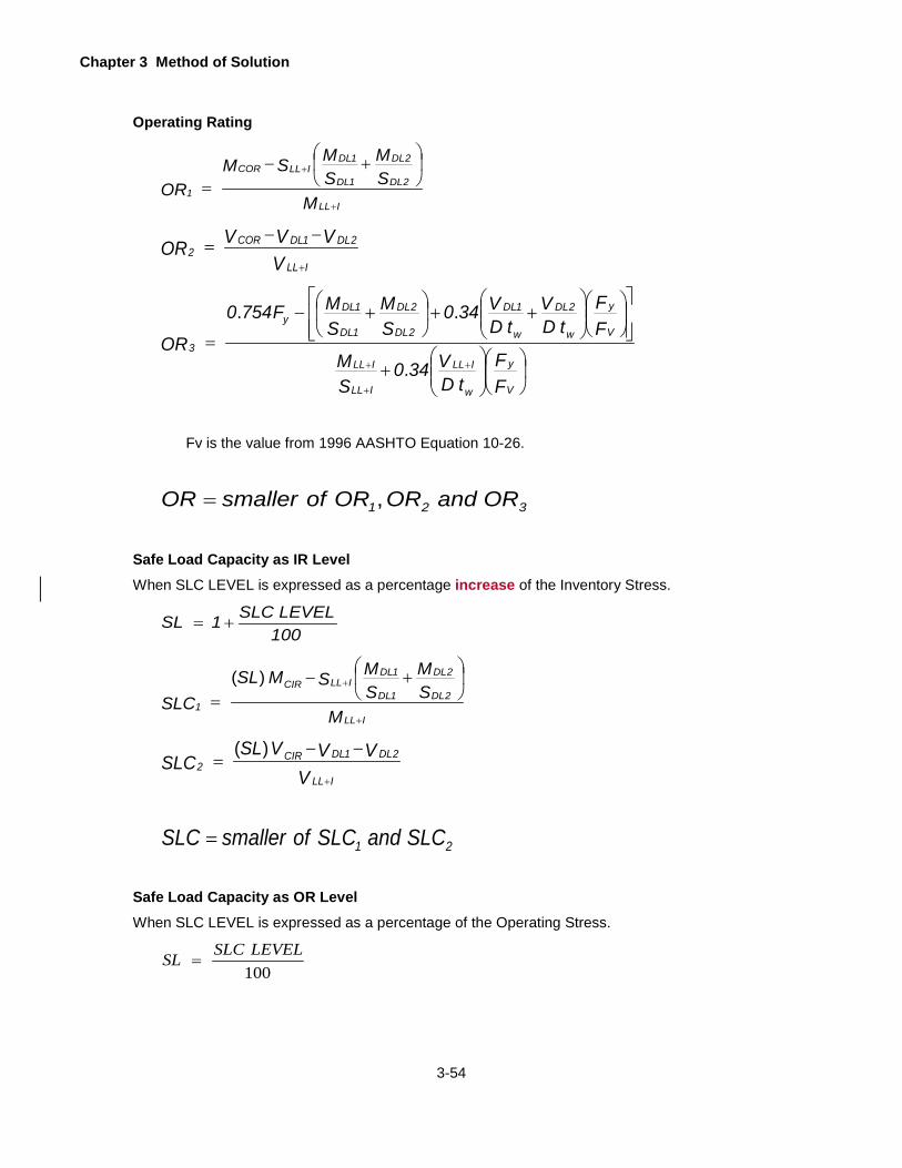
Chapter 3 Method of Solution
3-54
Operating Rating
MSM
SMSM
ORILL
2DL
2DL
1DL
1DLILLCOR
1+
+
+−
=
VVVVOR
ILL
2DL1DLCOR2
+
−−=
+
++
+−
=+
+
+
FF
tDV340
SM
FF
tDV
tDV340
SM
SMF7540
OR
V
y
w
ILL
ILL
ILL
V
y
w
2DL
w
1DL
2DL
2DL
1DL
1DLy
3
.
..
Fv is the value from 1996 AASHTO Equation 10-26.
321 ORandORORofsmallerOR ,=
Safe Load Capacity as IR Level When SLC LEVEL is expressed as a percentage increase of the Inventory Stress.
100LEVELSLC1SL +=
MSM
SMSMSL
SLCILL
2DL
2DL
1DL
1DLILLCIR
1+
+
+−
=)(
VVVVSL
SLCILL
2DL1DLCIR2
+
−−=
)(
21 SLCandSLCofsmallerSLC =
Safe Load Capacity as OR Level When SLC LEVEL is expressed as a percentage of the Operating Stress.
100LEVELSLCSL =
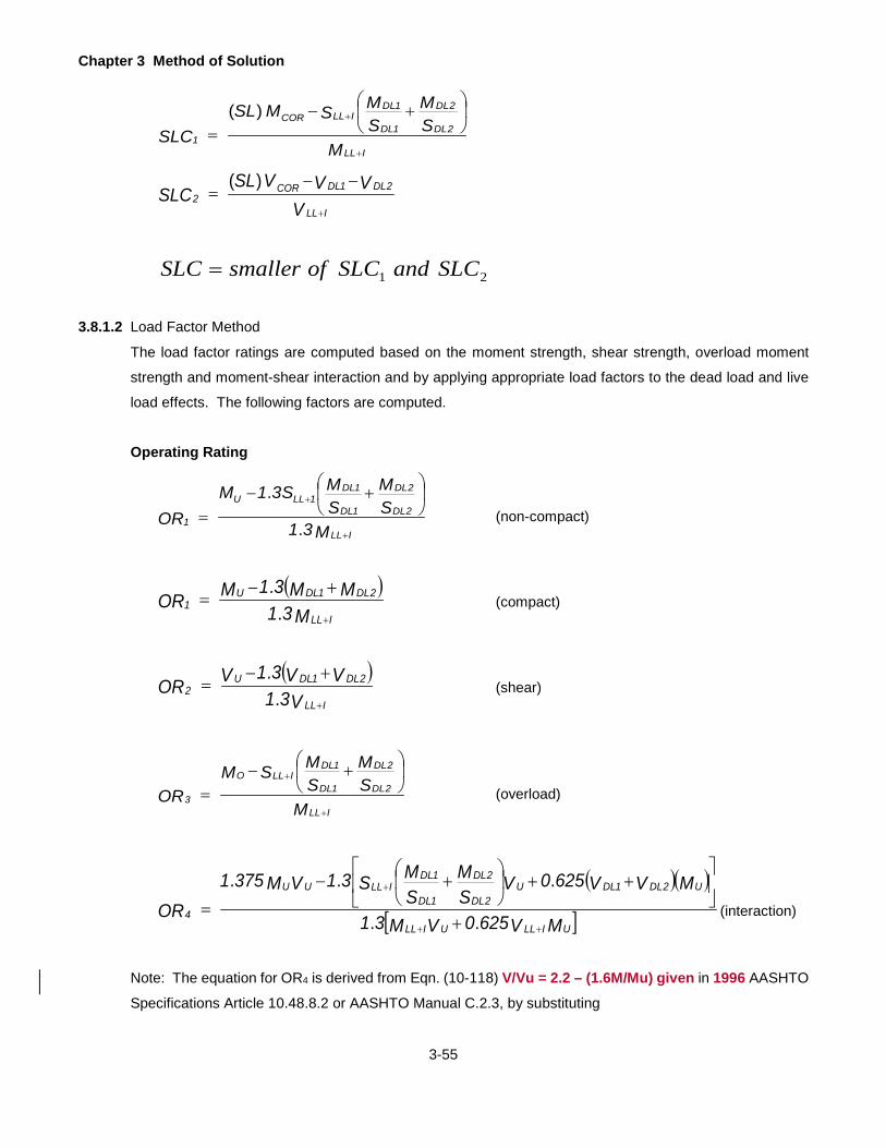
Chapter 3 Method of Solution
3-55
MSM
SMSMSL
SLCILL
2DL
2DL
1DL
1DLILLCOR
1+
+
+−
=)(
VVVVSL
SLCILL
2DL1DLCOR2
+
−−=
)(
21 SLCandSLCofsmallerSLC =
3.8.1.2 Load Factor Method
The load factor ratings are computed based on the moment strength, shear strength, overload moment
strength and moment-shear interaction and by applying appropriate load factors to the dead load and live
load effects. The following factors are computed.
Operating Rating
M31SM
SMS31M
ORILL
2DL
2DL
1DL
1DL1LLU
1+
+
+−
=.
.(non-compact)
( )M31
MM31MORILL
2DL1DLU1
+
+−=
..
(compact)
( )V31
VV31VORILL
2DL1DLU2
+
+−=
..
(shear)
MSM
SMSM
ORILL
2DL
2DL
1DL
1DLILLO
3+
+
+−
= (overload)
( )( )
[ ]MV6250VM31
MVV6250VSM
SMS31VM3751
ORUILLUILL
U2DL1DLU2DL
2DL
1DL
1DLILLUU
4++
+
+
++
+−
=..
...(interaction)
Note: The equation for OR4 is derived from Eqn. (10-118) V/Vu = 2.2 – (1.6M/Mu) given in 1996 AASHTO
Specifications Article 10.48.8.2 or AASHTO Manual C.2.3, by substituting
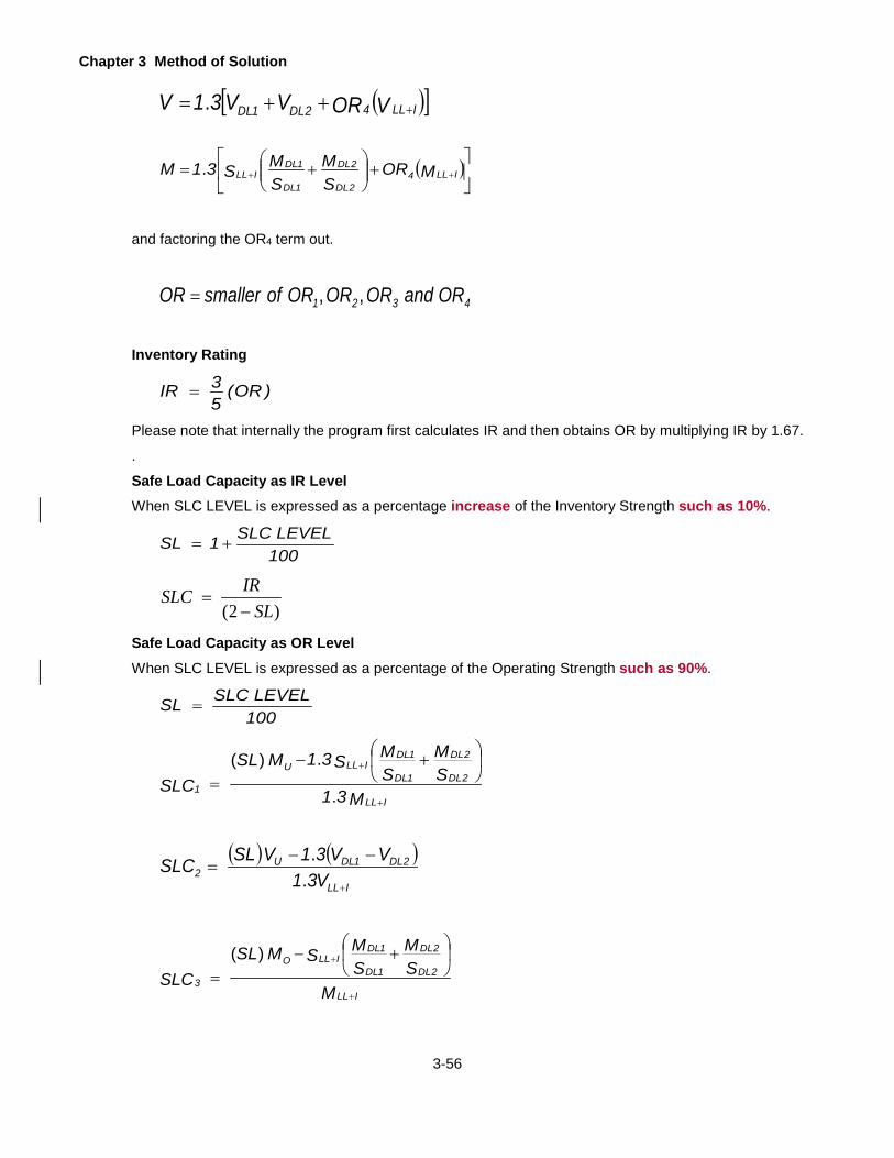
Chapter 3 Method of Solution
3-56
( )[ ]VORVV31V ILL42DL1DL +++= .
( )
+
+= ++ MOR
SM
SMS31M ILL4
2DL
2DL
1DL
1DLILL.
and factoring the OR4 term out.
4321 ORandORORORofsmallerOR ,,=
Inventory Rating
)OR(53IR =
Please note that internally the program first calculates IR and then obtains OR by multiplying IR by 1.67.
.
Safe Load Capacity as IR Level When SLC LEVEL is expressed as a percentage increase of the Inventory Strength such as 10%.
100LEVELSLC1SL +=
)2( SLIRSLC−
=
Safe Load Capacity as OR Level When SLC LEVEL is expressed as a percentage of the Operating Strength such as 90%.
100LEVELSLCSL =
M31SM
SMS31MSL
SLCILL
2DL
2DL
1DL
1DLILLU
1+
+
+−
=.
.)(
( ) ( )ILL
2DL1DLU2 V31
VV31VSLSLC+
−−=
..
MSM
SMSMSL
SLCILL
2DL
2DL
1DL
1DLILLO
3+
+
+−
=)(

Chapter 3 Method of Solution
3-57
( )MV6250VM31
MVV6250VSM
SMS31VMSL3751
SLCUILLUILL
U2DL1DLU2DL
2DL
1DL
1DLILLUU
4++
+
+
++
+−
=..
))((..)(.
4321 SLCandSLCSLCSLCofsmallerSLC ,,=
3.8.2 Flexural Concrete Members
Based on the moments, shears, capacities, and strengths calculated as explained earlier, the program
computes the following rating factors based on the Allowable Stress and Load Factor Methods.
3.8.2.1 Allowable Stress Method
The allowable stress ratings are computed based on various section capacities computed as explained
earlier and then subtracting the dead load effect to get the available capacity for live load. The rating factor
is obtained by dividing the available capacity by the live load plus impact effect. The following rating factors
are computed.
Inventory Rating
ILL
DLCIR1 M
MMIR+
−=
ILL
DLCIR2 V
VVIR+
−=
21 IRandIRofsmallerIR =Operating Rating
ILL
DLCOR1 M
MMOR+
−=
ILL
DLCOR2 V
VVOR+
−=
21 ORandORofsmallerOR =
Safe Load Capacity as IR Level When SLC LEVEL is expressed as a percentage increase of the Inventory Stress.
100LEVELSLC1SL +=
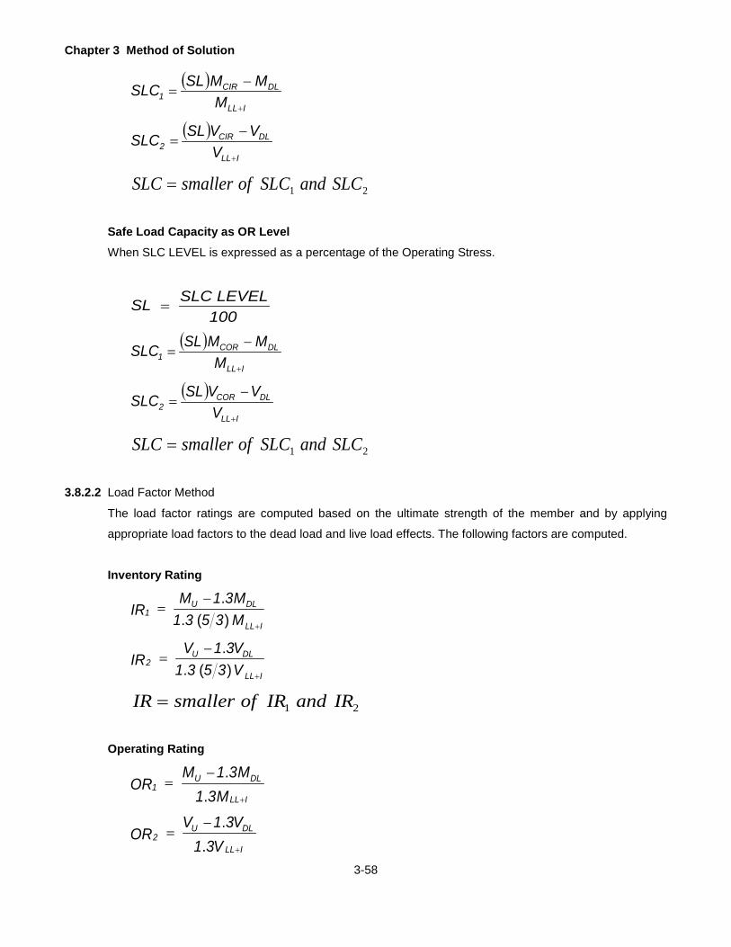
Chapter 3 Method of Solution
3-58
( )ILL
DLCIR1 M
MMSLSLC+
−=
( )ILL
DLCIR2 V
VVSLSLC+
−=
21 SLCandSLCofsmallerSLC =
Safe Load Capacity as OR Level When SLC LEVEL is expressed as a percentage of the Operating Stress.
100LEVELSLCSL =
( )ILL
DLCOR1 M
MMSLSLC+
−=
( )ILL
DLCOR2 V
VVSLSLC+
−=
21 SLCandSLCofsmallerSLC =
3.8.2.2 Load Factor Method
The load factor ratings are computed based on the ultimate strength of the member and by applying
appropriate load factors to the dead load and live load effects. The following factors are computed.
Inventory Rating
M3531M31M
IRILL
DLU1 )(.
.
+
−=
V3531V31V
IRILL
DLU2 )(.
.
+
−=
21 IRandIRofsmallerIR =
Operating Rating
M31M31M
ORILL
DLU1
..
+
−=
V31V31V
ORILL
DLU2
..
+
−=

Chapter 3 Method of Solution
3-59
21 ORandORofsmallerOR =
Safe Load Capacity as IR Level When SLC LEVEL is expressed as a percentage increase of the Inventory Strength.
1001 LEVELSLCSL +=
)2( SLIRSLC−
=
Safe Load Capacity as OR Level
When SLC LEVEL is expressed as a percentage of the Operating Strength.
100LEVELSLCSL =
( )ILL
DLU1 M31
M31MSLSLC+
−=
..
( )ILL
DLU2 V31
V31VSLSLC+
−=
..
21 SLCandSLCofsmallerSLC =
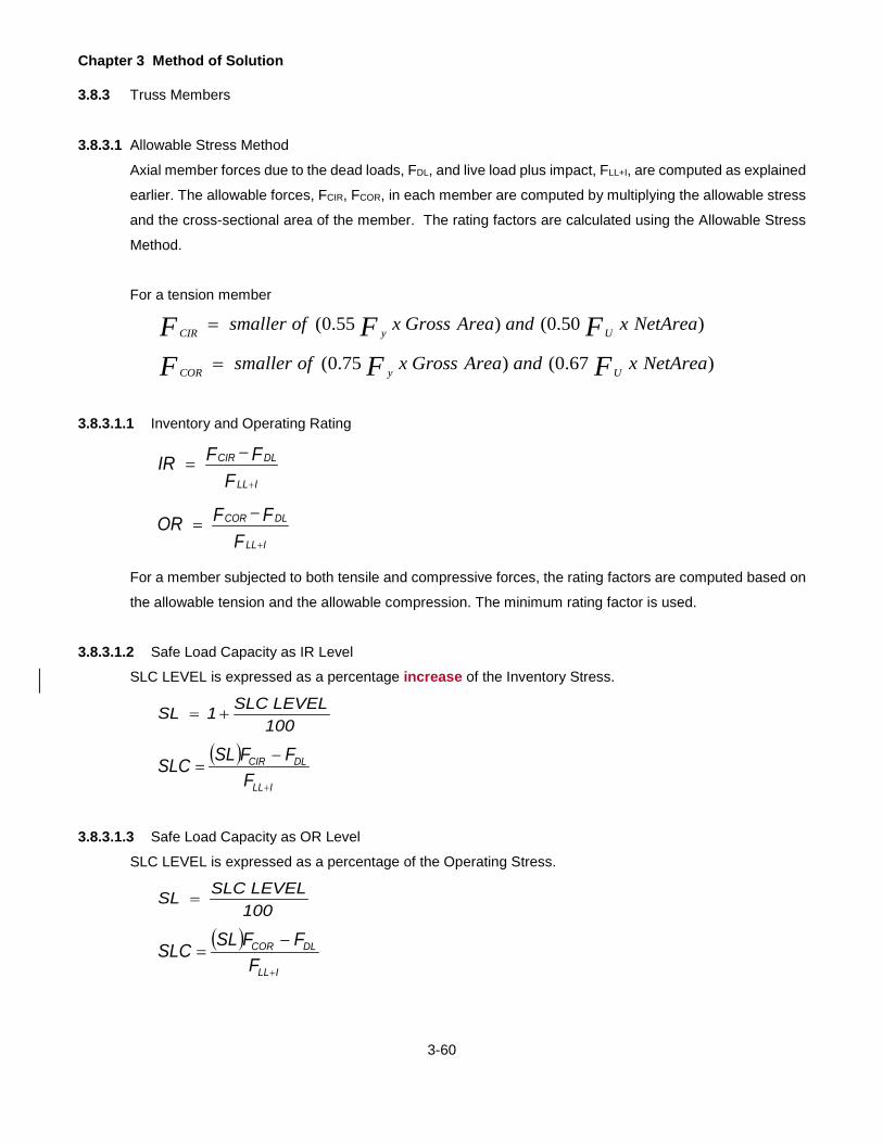
Chapter 3 Method of Solution
3-60
3.8.3 Truss Members
3.8.3.1 Allowable Stress Method
Axial member forces due to the dead loads, FDL, and live load plus impact, FLL+I, are computed as explained
earlier. The allowable forces, FCIR, FCOR, in each member are computed by multiplying the allowable stress
and the cross-sectional area of the member. The rating factors are calculated using the Allowable Stress
Method.
For a tension member
)50.0()55.0( NetAreaxandAreaGrossxofsmaller FFF UyCIR =
)67.0()75.0( NetAreaxandAreaGrossxofsmaller FFF UyCOR =
3.8.3.1.1 Inventory and Operating Rating
FFFIRILL
DLCIR
+
−=
FFFORILL
DLCOR
+
−=
For a member subjected to both tensile and compressive forces, the rating factors are computed based on
the allowable tension and the allowable compression. The minimum rating factor is used.
3.8.3.1.2 Safe Load Capacity as IR Level
SLC LEVEL is expressed as a percentage increase of the Inventory Stress.
100LEVELSLC1SL +=
( )ILL
DLCIR
FFFSLSLC
+
−=
3.8.3.1.3 Safe Load Capacity as OR Level
SLC LEVEL is expressed as a percentage of the Operating Stress.
100LEVELSLCSL =
( )ILL
DLCOR
FFFSLSLC
+
−=
Chapter 3 Method of Solution
3-61
3.8.3.2 Load Factor Method
Axial member forces due to the factored dead loads, PDL, and factored live load plus impact, PLL+I, are
computed as explained earlier. The member capacities, Pu, in each member are computed accordingly.
The rating factors are calculated using the Load Factor Method.
For truss spans over 500 feet long, LFD loads used for the supplementary check of capacity have been
factored per Group I in accordance with the AASHTO Guide Spec for Truss. Article 1.2. That is:
If PDL ≤ 0.77 * (PDL + PLL+I ), then it is case 1:
PTOT = 1.3*(PDL +(5/3)*PLL+I)
If PDL > 0.77 * (PDL + PLL+I), then it is case 2:
PTOT = 1.5**(PDL +PLL+I)
where: PDL = total force due to factored dead loads
PLL+I = total force due to factored live load (live load + impact)
PTOT = total force due to total factored load
For truss spans less than 500 feet long, use case 1 LFD loads for the supplementary check of capacity.
The load factor ratings are computed based on the ultimate strength of the member and by applying
appropriate load factors to the dead load and live load effects. For a member subjected to both tensile and
compressive forces, the rating factors are computed based on the tension and the compression. The
minimum rating factor is used.
3.8.3.2.1 Inventory Rating
Case 1:
IR1 = (Pu - 1.3*PDL) / (1.3*(5/3)*PLL+I)
Case 2:
IR2 = (Pu - 1.5*PDL) / (1.5*PLL+I)
IR = smaller of IR1 and IR2
3.8.3.2.2 Operating Rating
Case1:
OR1 = (Pu - 1.3*PDL) / (1.3*PLL+I)

Chapter 3 Method of Solution
3-62
Case 2:
OR2 = (Pu - 1.5*PDL) / (1.5*(5/3)*PLL+I)
OR = smaller of OR1 and OR2
Note: The program did not use the “IR = (3/5)*OR” which can be used to verify the program result manually.
3.8.3.2.3 Safe Load Capacity as IR Level
SLC LEVEL is expressed as a percentage of the Inventory Strength.
SL = 1 + SLC LEVEL/100
SLC = IR/(2-SL)
3.8.3.2.4 Safe Load Capacity as OR Level
SLC LEVEL is expressed as a percentage of the Operating Strength.
SL = SLC LEVEL/100
Case 1:
SLC1 = (SL*Pu - 1.3*PDL) / (1.3*(5/3)*PLL+I)
Case 2:
SLC2 = (SL*Pu - 1.5*PDL) / (1.5*(5/3)*PLL+I)
SLC = smaller of SLC1 and SLC2

Chapter 3 Method of Solution
3-63
DEFLECTIONS
3.9.1 Simple Span Beam or Girder
Deflections of a simple span beam or girder are computed using the conjugate beam method. For this,
moments are computed at the 10th point sections assuming a unit uniform load acting on the entire span.
Each moment is divided by the flexural rigidity (EΙ) of the section and a conjugate beam with an M/EΙ loading
is constructed. The moment at any section of the conjugate beam due to M/EΙ loading is the deflection of
the real beam. Actual dead load deflections are computed by multiplying the unit uniform load deflections
with the actual dead load acting on the beam.
The influence lines for deflections are generated by applying a unit vertical load at each 10th point section
at a time and computing deflections for each loading condition as described above. Each deflection
influence line is then analyzed for a live load to obtain the live load plus impact deflection.
3.9.2 Continuous Span Girder
Deflections of a continuous span girder are obtained by the modified flexibility method as described in
Section 3.3.1. For each loading condition (either a unit uniform load on the entire girder or a unit vertical
load at a given section), the support reactions and joint deflections are computed by multiplying the inverted
flexibility matrix and the load matrix. For details of this method, refer to Analysis of Framed Structures by
Gere and Weaver, Van Nostrand Publication. Actual dead load deflections are computed by multiplying
the unit load deflections with the actual dead load acting on the girder.
The influence lines for deflections are generated by applying a unit vertical load at each 10th point section
at a time and solving the matrices explained above. Each deflection influence line is then analyzed for a
live load to obtain the live load plus impact deflections.
3.9.3 Truss
The dead load deflections are computed by the unit load method. The live load deflections are computed
by the influence line method. Deflections due to temperature change are computed based on the method
of virtual work. For these methods refer to any standard textbook on structural engineering.

Chapter 3 Method of Solution
3-64
FATIGUE LIFE ESTIMATION
The program calculates the fatigue life of a girder or truss based on the criteria set forth in "Policy and Procedures,
Chapter 5, Rehabilitation Strategy," of DM4. Figure 3.10.1 on page 3-67 shows the flow chart of the calculations
performed by BAR7 for the fatigue life analysis of a girder or truss.
3.10.1 Girder
The fatigue life of a girder is calculated by evaluating each fatigue prone detail specified by the user. The
program calculates the design fatigue stress range and the allowable fatigue stress range at each detail.
The design fatigue stress range at a detail is calculated as follows. The maximum positive moment and the
maximum negative moment at a detail are calculated by parabolic interpolation of the 10th point moments
calculated earlier. The live load plus impact moment calculated for fatigue life analysis is based on AASHTO
Simplified Method by placing a single HS20 truck with a fixed spacing of 14 feet between its rear axles in
one lane. The stresses at a detail due to the dead load plus positive live load moment and due to the dead
load plus negative live load moment are then calculated using appropriate section moduli. The algebraic
difference of the maximum stress (DL+LL) and the minimum stress is the design fatigue stress range. If
the detail never experiences a tensile stress, i.e. the detail always remains in compression under dead load
and live load plus impact, the program assumes that the design fatigue stress range is zero. The allowable
fatigue stress range is calculated per AASHTO Specifications Table 10.3.1A for over 2,000,000 cycles.
The program then compares the design fatigue stress range due to an HS20 truck in one lane to the
allowable fatigue stress range. If the design fatigue stress range due to an HS20 truck in one lane is less
than or equal to the allowable fatigue stress range, or if the design fatigue stress range is zero, the program
assumes that the detail has infinite fatigue life and no further analysis is required. If the PTF*design fatigue
stress range due to an HS20 truck in one lane is greater than the allowable fatigue stress range, the
program computes the effective stress range. The effective stress range is the design fatigue stress range
due to an HS20 truck in one lane multiplied by the appropriate factors given in DM4. The design fatigue life
(minimum number of cycles to failure) and the remaining fatigue life (years) of each detail are calculated
using the equations given in Figure 3.10.1 on page 3-67
If the user wants to consider a growth factor in the average daily truck traffic, the program uses the following
engineering economy equations to calculate the accumulated cycles and the remaining life in years.
If the ADTT's are known for two calendar years (previous count year n1 and recent count year n2), the
program calculates the past growth factor, GF1 by:
( ) ( )[ ]( )n112 GF1nADTTnADTT += where n = n2 – n1
Chapter 3 Method of Solution
3-65
The previous equation is not used if GF1 is known (or estimated) and is entered. This growth factor, GF1,
is then used to approximate the ADTT for the year the structure was built as follows:
( ) ( )( )n
1
2
GF1nADTTbuiltyearADTT
+= where n = n2 – year built
The number of cycles accumulated up to the year n2 is computed by:
( ) ( )[ ] ( )
−+=
1
n1
GF1GF1builtyearADTT365M where n = n2 – year built
If the estimated ADTT for a future count year, n3, is entered, the future growth factor, GF2, is calculated by:
( ) ( )[ ] ( )n223 GF1nADTTnADTT += where n = n3 – n2
The above equation is not used if GF2 is known (or estimated) and is entered.
The remaining life (years) is then calculated using the following, which is derived from the engineering
economy equation for compound amount:
( )2
2
GF1
1GFx
R+
+∆
=ln
lnλ
where R = remaining years
∆ = remaining cycles
= design fatigue life – accumulated cycles
= N – M
GF2 = future growth factor
λ = (365)[ADTT (n2)] (1+GF2)
ln = natural log
The future growth factor can be estimated and entered or can be calculated by the program if the estimated
ADTT for future is entered.
The minimum fatigue life for the girder and the location of critical detail are printed out.

Chapter 3 Method of Solution
3-66
3.10.2 Truss
The estimated fatigue life of each truss member for which a fatigue life analysis is requested is calculated
in the same manner as described for the girder. The maximum positive (tension) axial force and the
maximum negative (compression) axial force due to an HS20 truck with a fixed spacing of 14 feet between
its rear axles are calculated for each member using the influence line method. The stresses due to dead
load force plus maximum positive live load force and due to dead load force plus maximum negative live
load force are then calculated using appropriate cross sectional areas. The algebraic difference of the
maximum stress and the minimum stress is the design fatigue stress range. If the detail never experiences
a tensile stress, i.e. the detail always remains in compression under dead load and live load plus impact,
the program assumes that the design stress range is zero.
The allowable fatigue stress range, the estimated fatigue life and the remaining fatigue life of each member
are then calculated in the same manner as described for the girder. The minimum fatigue life for the truss
and the critical member are printed out.

Chapter 3 Method of Solution
3-67
Figure 3.10.1 Fatigue Life Estimation Flow Chart
Determine Allowable Fatigue StressRange Fsr per AASHTO Table
10.3.1AUse > 2,000,000 Cycles
Find Distribution Factor DF1 for
one lane per AASHTO 3.23Use AASHTO Simplified Method
Calculate Design Fatigue Stress
Range (fsr )D based on DF1Use HS20 Truck in one lane
(fsr )D PTF ≤ Fsr
No
Yes
Fatigue
Life is
Infinite
α = 0.5 For AASHTO Simplified Method
Print FatigueLife as9999
END
A
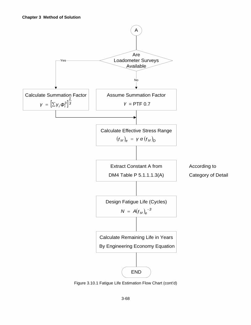
Chapter 3 Method of Solution
3-68
Figure 3.10.1 Fatigue Life Estimation Flow Chart (cont’d)
AreLoadometer Surveys
AvailableYes
Calculate Summation Factor Assume Summation Factor
= PTF 0.7
According to
Category of Detail
END
A
No
[ ] 31
3ii Φγγ ∑=
Calculate Effective Stress Range
( ) ( )Dsresr fαγf =
Extract Constant A from
DM4 Table P 5.1.1.1.3(A)
Design Fatigue Life (Cycles)
( ) 3esrfAN −=
Calculate Remaining Life in Years
By Engineering Economy Equation
γ
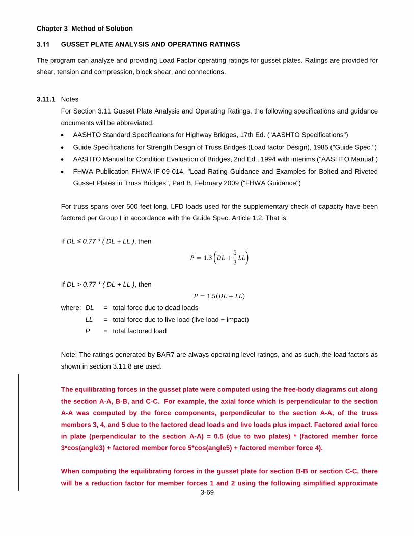
Chapter 3 Method of Solution
3-69
GUSSET PLATE ANALYSIS AND OPERATING RATINGS
The program can analyze and providing Load Factor operating ratings for gusset plates. Ratings are provided for
shear, tension and compression, block shear, and connections.
3.11.1 Notes
For Section 3.11 Gusset Plate Analysis and Operating Ratings, the following specifications and guidance
documents will be abbreviated:
• AASHTO Standard Specifications for Highway Bridges, 17th Ed. ("AASHTO Specifications")
• Guide Specifications for Strength Design of Truss Bridges (Load factor Design), 1985 ("Guide Spec.")
• AASHTO Manual for Condition Evaluation of Bridges, 2nd Ed., 1994 with interims ("AASHTO Manual")
• FHWA Publication FHWA-IF-09-014, "Load Rating Guidance and Examples for Bolted and Riveted
Gusset Plates in Truss Bridges", Part B, February 2009 ("FHWA Guidance")
For truss spans over 500 feet long, LFD loads used for the supplementary check of capacity have been
factored per Group I in accordance with the Guide Spec. Article 1.2. That is:
If DL ≤ 0.77 * ( DL + LL ), then
𝑃𝑃 = 1.3 �𝐷𝐷𝐷𝐷 +53𝐷𝐷𝐷𝐷�
If DL > 0.77 * ( DL + LL ), then
𝑃𝑃 = 1.5(𝐷𝐷𝐷𝐷 + 𝐷𝐷𝐷𝐷)
where: DL = total force due to dead loads
LL = total force due to live load (live load + impact)
P = total factored load
Note: The ratings generated by BAR7 are always operating level ratings, and as such, the load factors as
shown in section 3.11.8 are used.
The equilibrating forces in the gusset plate were computed using the free-body diagrams cut along the section A-A, B-B, and C-C. For example, the axial force which is perpendicular to the section A-A was computed by the force components, perpendicular to the section A-A, of the truss members 3, 4, and 5 due to the factored dead loads and live loads plus impact. Factored axial force in plate (perpendicular to the section A-A) = 0.5 (due to two plates) * (factored member force 3*cos(angle3) + factored member force 5*cos(angle5) + factored member force 4).
When computing the equilibrating forces in the gusset plate for section B-B or section C-C, there will be a reduction factor for member forces 1 and 2 using the following simplified approximate

Chapter 3 Method of Solution
3-70
formula: Reduction Factor = ((4*diameter + distance between the first row and last row) - eccentricity) / (4*diameter + distance between the first row and last row)
3.11.2 General
Fy = specified minimum yield stress of the gusset plate material
Fu = specified minimum tensile stress of the gusset plate material (1.4 Fy is used as a default value if
Fu was not input)
3.11.3 Shear Capacity
Gusset plates subjected to shear shall be investigated for two conditions: gross shear yielding and net
section fracture. The shear capacity is the lesser of these two conditions. A factor of 0.74 will be used for
the shear stress distribution.
Gross Shear Yielding (FHWA Guidance, Equation 6):
𝐹𝐹𝑣𝑣𝑣𝑣 = 0.58 𝐹𝐹𝑦𝑦 0.74 = 0.429 𝐹𝐹𝑦𝑦
𝑃𝑃𝑣𝑣𝑣𝑣 = 𝐹𝐹𝑣𝑣𝑣𝑣 𝐴𝐴𝑣𝑣
where: Fvg = shear stress capacity
Fy = yield stress of the gusset plate
Pvg = shear capacity
Ag = area of the gusset plate resisting the shear
0.74 = a factor used in the absence of a more rigorous analysis or criterion to assure and quantify
the stiffness requirements to develop the plastic shear force of the plates
Net Section Fracture (FHWA Guidance, Equation 7):
𝐹𝐹𝑣𝑣𝑣𝑣 = 0.85 𝑥𝑥 0.58 𝐹𝐹𝑢𝑢 = 0.493 𝐹𝐹𝑢𝑢
𝑃𝑃𝑣𝑣𝑣𝑣 = 𝐹𝐹𝑣𝑣𝑣𝑣 𝐴𝐴𝑣𝑣
where: Fvn = shear stress capacity
Fu = tensile stress of the gusset plate
Pvn = shear capacity
An = area of the gusset plate (less holes) resisting the shear
0.85 = resistance factor for shear fracture on the net section
Chapter 3 Method of Solution
3-71
3.11.4 Capacity Equations to Analyze Gusset Plates at the End of All Members for Tension and at the End of the Diagonal and Vertical chords for Compression
3.11.4.1 Gusset Plate in Tension
Gusset plates subjected to axial tension shall be investigated for two conditions: yield on the effective gross
section and fracture on the net section. For both yielding on the gross section and fracture on the net section,
the Whitmore method (i.e. 30° distribution) will be used to determine the "effective width" to calculate the
gross area in tension (See Figure 3.11.1 on page 3-76 at the end of this section).
Effective Gross Section Yielding (FHWA Guidance, Equation 2):
𝑅𝑅𝑟𝑟 = 𝐴𝐴𝑒𝑒𝐹𝐹𝑦𝑦
where: Rr = effective gross section yield capacity
Ae = effective gross cross-sectional area taking into account the possibility of net section
fracture
= An + βAg ≤ Ag
An = net cross-sectional area of the plates as specified in AASHTO Specifications Article
10.16.14
β = 0.0 for M 270 Grade 100/100W steels, or when holes exceed 1¼ inch in diameter
= 0.15 for all other steels and when holes are less than or equal to 1¼ inch in diameter
Ag = gross cross-sectional area of the plates
Fy = yield strength of the gusset plate
3.11.4.2 Gusset Plate in Compression
Gusset plates subjected to compression will be analyzed as an idealized column. This method is generally
conservative when compared to the capacity obtained using plate buckling theory. The adequacy of the
gusset plate at the end of the diagonal due to a compressive diagonal axial force will also be investigated.
Buckling at the end of the compression diagonal will be the assumed failure mode in compression.
Therefore, compression must be checked on the effective width line (using the Whitmore method, i.e. 30°
distribution) at the end of the diagonal (See Figure 3.11.1 on page 3-76 at the end of this section).
According to FHWA Guidance, the effective width of the idealized compression member may be determined
in accordance with the Whitmore method. The unbraced length, Lc, may be determined as the average of
three distances (LC#-1, LC#-2 ,LC#-3 ) as follows:
where: LC#-2 = distance from the last row of fasteners in the compression member under
consideration to the first row of fasteners in the closest adjacent member, measured

Chapter 3 Method of Solution
3-72
along the line of action of the compressive axial force (See Figure 3.11.1 on page 3-
76 at the end of this section).
LC#-1,LC#-3 = distance from each of the ends of the Whitmore width to the first row of fasteners in
the closest adjacent member, measured parallel to the line of action of the
compressive axial force. When the Whitmore width enters into the adjacent member,
the associated distance at that end should be set to zero (See Figure 3.11.1 on page
3-76 at the end of this section).
Use the capacity equation provided in AASHTO Specifications Article 10.54.1.1 for compression in
concentrically loaded columns.
Pc = compression strength along effective width based on Ag Fa
where: Ag = effective width x gusset plate thickness
Determine the compressive capacity, Fa, using column theory:
𝐹𝐹𝑎𝑎 = 0.85 𝐹𝐹𝑐𝑐𝑟𝑟 AASHTO Eq. 10-150
if: 𝐾𝐾𝐿𝐿𝑐𝑐𝑟𝑟≤ 𝐶𝐶𝑐𝑐
then
𝐹𝐹𝑐𝑐𝑟𝑟 = 𝐹𝐹𝑦𝑦 �1 − � 𝐹𝐹𝑦𝑦4 𝜋𝜋2𝐸𝐸
� �𝐾𝐾 𝐿𝐿𝑐𝑐𝑟𝑟�2� AASHTO Eq. 10-151
where: Fcr = critical stress
if: 𝐾𝐾 𝐿𝐿𝑐𝑐𝑟𝑟
> 𝐶𝐶𝑐𝑐
𝐹𝐹𝑐𝑐𝑟𝑟 = � 𝜋𝜋2𝐸𝐸
�𝐾𝐾 𝐿𝐿𝑐𝑐𝑟𝑟 �
2� AASHTO Eq. 10-153
where: Fcr = critical stress
K = effective length factor, K, used in the column capacity equation for the unsupported length
at the end of the compression diagonal is taken to be 2.0 if the gusset plate analysis shows
that the plate has yielded due to shear on Section A-A, otherwise it is taken as 1.2.
(AASHTO Appendix C, Table C.1)

Chapter 3 Method of Solution
3-73
Cc = �𝟐𝟐 𝝅𝝅𝟐𝟐𝑬𝑬𝑭𝑭𝒚𝒚
r = radius of gyration of the plate
= 𝒕𝒕
√𝟏𝟏𝟐𝟐
E = modulus of elasticity of steel
Lc = Lc3, 4 or 5
= average distance between the last row of fasteners in the diagonal / vertical to the closest
row of fasteners in the chord measured along the line of action of the diagonal / vertical
(shown in Figure 5.22.1 on page 5-97 to Figure 5.22.4 on page 5-100)
3.11.5 Block Shear Rupture Capacity for Any Member Connection at a Joint
For the block shear rupture planes, please refer to Figure 3.11.2 on page 3-77 at the end of this section.
The 1.25 factor is used to convert the capacity to an Operating Level capacity and was determined by
dividing the Inventory Euler buckling Factor of Safety (2.12) by the Operating Euler buckling Factor of Safety
(1.70). (Refer to AASHTO Manual Section 6.6.2.1-1)
if
𝐴𝐴𝑡𝑡𝑣𝑣 ≥ 0.58 𝐴𝐴𝑣𝑣𝑣𝑣
then
𝑃𝑃𝑏𝑏𝑏𝑏 = 0.85 �0.58 𝐹𝐹𝑦𝑦𝐴𝐴𝑣𝑣𝑣𝑣 + 𝐹𝐹𝑢𝑢𝐴𝐴𝑡𝑡𝑣𝑣� FHWA Guidance Eq. 4 at Sec 3.1.2
where: Avg = gross area along the plane resisting shear stress
Atn = net area along the plane resisting tension stress
0.85 = resistance factor for block shear
Otherwise,
𝑃𝑃𝑏𝑏𝑏𝑏 = 0.85 �0.58 𝐹𝐹𝑢𝑢𝐴𝐴𝑣𝑣𝑣𝑣 + 𝐹𝐹𝑦𝑦𝐴𝐴𝑡𝑡𝑣𝑣� FHWA Guidance Eq. 5 at sec 3.1.2
where: Avg = net area along the plane resisting shear stress
Atn = gross area along the plane resisting tension stress
0.85 = resistance factor for block shear
Chapter 3 Method of Solution
3-74
3.11.6 Connection Capacities
In typical connection design, the connection is designed for the average of the design strength of the
diagonals and the factored/service loads they carry, however, the axial force shall not be less than 75% of
the design strength. The design strength is the lesser of the member strength, column capacity and strength
based on the width-thickness ratio b/t.
For rating evaluation, the adequacy of the fasteners under the factored axial load is checked for fastener
shear and bearing on connected material. The member forces are assumed to be distributed equally among
all fasteners.
Slip-critical connections are assumed for normal truss connection designs, however, if rivets or low-carbon
steel bolts (A307) are specified on the plans, the connection is bearing-type, only high strength bolts can
support the high preload necessary for slip-critical connections. In any case, bearing should always be
checked if the connection slips due to insufficient tension in the fasteners.
This program does not check bearing strength of the fastener.
3.11.6.1 Investigate the Fasteners in Shear
𝑃𝑃 ≤ 𝑅𝑅𝑣𝑣
where: Rv = shear capacity of all bolts or rivets in connection from AASHTO Specifications Article
10.56.1.3.2
𝑅𝑅𝑣𝑣 = 𝐹𝐹𝑣𝑣_𝐿𝐿𝐹𝐹𝐿𝐿 𝐴𝐴𝑓𝑓 𝑁𝑁𝑓𝑓 AASHTO Eq. 10-166a
where: Fv_LFD = shear capacity of one bolt or rivet (AASHTO Specifications Table 10.56A may be used)
Af = area of one fastener, bolt or rivet
Nf = total number of shear planes in fasteners connecting the member to the gusset.
3.11.6.2 Investigate Bearing on the Connected Material
The holes should be assumed to be standard size. Also, the total bearing capacity for the connection is
equal to the sum of the bearing capacity for the individual fasteners in the connection. Use the provisions
of AASHTO Specifications Article 10.56.1.3.2.
𝑃𝑃 ≤ 𝑅𝑅𝑏𝑏
where: Rb = capacity of connection in bearing
= the result of 0.9 Lc t Fu ≤ 1.8 d t Fu (AASHTO Eq. 10-166b) multiplied by the respective
number of fasteners, Nf. (See Nf in Section 3.11.6.1 for more information)
Chapter 3 Method of Solution
3-75
where: Lc = Le or Lo
= clear distance between the holes, Lo, or between the hole and the edge of the material,
Le, in the direction of the applied bearing force
Le = 2d for edge holes
Lo = average clear distance between the holes which is calculated by the program as Lo = L#
/ (NL# - 1) - hole diameter for all other
t = thickness of the connected material
Fu = specified minimum tensile strength of the connected material
d = nominal diameter of the fastener
3.11.7 Unsupported Edge in Compression Adequacy Check
Check b/t for every free edge on the gusset plate. If the check fails, then the edge shall be stiffened (Guide
Spec., Article 1.11)
𝑏𝑏𝑡𝑡≤
11000
�𝐹𝐹𝑦𝑦
where: b = maximum unsupported length along edge of gusset plate
t = thickness of the gusset plate
Fy = yield strength of the gusset plate
3.11.8 Operating Level Rating Equations
𝑅𝑅𝐹𝐹 =𝑁𝑁𝑁𝑁𝑁𝑁𝑁𝑁𝑁𝑁𝑁𝑁𝑁𝑁 𝐶𝐶𝑁𝑁𝐶𝐶𝑁𝑁𝐶𝐶𝑁𝑁𝑡𝑡𝐶𝐶 − 1.3 𝐷𝐷𝐷𝐷𝑁𝑁𝐷𝐷 𝐷𝐷𝑁𝑁𝑁𝑁𝐷𝐷
1.3 (𝐷𝐷𝑁𝑁𝐿𝐿𝐷𝐷 𝐷𝐷𝑁𝑁𝑁𝑁𝐷𝐷 + 𝐼𝐼𝑁𝑁𝐶𝐶𝑁𝑁𝐶𝐶𝑡𝑡)AASHTO Manual Articles 6.5.1 and 6.5.2
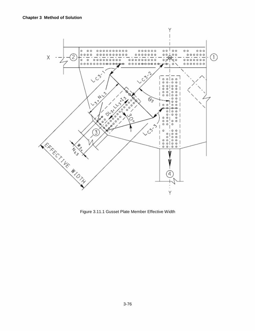
Chapter 3 Method of Solution
3-76
Figure 3.11.1 Gusset Plate Member Effective Width
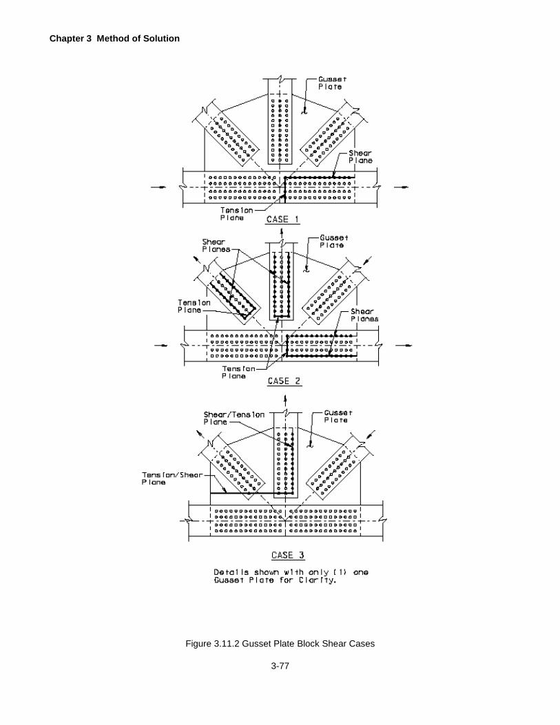
Chapter 3 Method of Solution
3-77
Figure 3.11.2 Gusset Plate Block Shear Cases
Chapter 3 Method of Solution
3-78
PONY TRUSS STABILITY CHECK
3.12.1 Notes
For the purpose of this section, Pony Truss Stability Check, the following specifications and guidance
documents will be used:
• AASHTO Specifications: Article 10.16.12 Half-through Truss Spans
• AASHTO LRFD Guide Specifications for the Design of Pedestrian Bridges, December 2009
• Chapter 14 of the Guide to Stability Design criteria for Metal Structures, 3rd Ed. By Bruce Johnston
The Pony Truss Stability Check can only be performed when the Load Factor Method analysis is selected.
Otherwise the program produces an error.
3.12.2 General
AASHTO specified the top chord shall be considered as a column with elastic lateral supports at the panel
points. AASHTO also specified that top chords and vertical members at a floorbeam locations of a pony
truss shall resist a lateral force applied at the top of the truss verticals. The applied lateral force shall not
be less than 0.01/K times the average factored design compressive force in the two adjacent top chords.
Therefore, the top chord stability check shall be performed at specified floorbeam location of a pony truss
which bridge type is TFS.
Note:
TFF: truss floorbeam steel bridge (no stringers)
No pony truss stability check will be performed because this is a deck truss.
TTT:
No pony truss stability check will be performed because there are no floorbeam and stringer analyses.
TFS: truss floorbeam stringer steel bridge
Only the pony truss will be checked. However, the upper diagonal chord stability check at specified
floorbeam location of a pony truss will not be checked because it is a tension member.
3.12.3 Logic
For this stability check, BAR7 will run twice. The first run will compute the spring constant and the member
LFD capacity using the BAR7-default K values depending on the pinned or riveted end condition selected
from the user. With member capacity and spring constant are known, we can find the computed pony-K
value. Compare the BAR7-default K value and computed pony-K value to obtain the controlling K value.
The second run will compute using the controlling k values.

Chapter 3 Method of Solution
3-79
3.12.4 Lookup Table for K Values
AASHTO specified the procedure for determining the resistance of a compression chord with a value for
the effective factor, K, based on a lateral U-frame. Use the lookup table from the AASHTO LRFD Guide
Specifications for the Design of Pedestrian Bridges, December 2009, Table 7.1.2-1: values of 1/K (1.000
to 0.085 for 30 values) for various values of CL/Pc and n (4 to 16). In addition, missing data will be linearly
interpolated if needed.
Where
K = effective length factor
C = transverse-frame spring constant which is the lateral stiffness of the U-frame made of the truss
vertical and the floorbeam taken as P/delta - kips/in
L = length of the chord between panel points - in
Pc = desired critical buckling load of the truss chord member, which shall be taken as 2.0 times the
factored compressive load – kips
n = number of panels in the pony truss
Linear interpolation rules for missing data in the lookup table:
For the values within the same n, the missing CL/Pc values will be linearly interpolated from two nearby
values.
For the values corresponding to the same 1/K for n = 5, 7, 9, 11, 13, and 15, the missing CL/Pc values will
be the average of the values from two nearby ns. For example: (CL/Pc for n = 5) = [(CL/Pc for n =
4) + (CL/Pc for n = 6)]/2
The number of panels must be between 4 and 16 because the limitations of the lookup table.
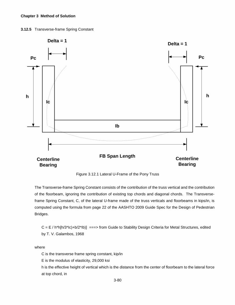
Chapter 3 Method of Solution
3-80
3.12.5 Transverse-frame Spring Constant
FB Span Length
Delta = 1
CenterlineBearing
CenterlineBearing
hIc Ic
Ib
Delta = 1
Pc Pc
h
Figure 3.12.1 Lateral U-Frame of the Pony Truss
The Transverse-frame Spring Constant consists of the contribution of the truss vertical and the contribution
of the floorbeam, ignoring the contribution of existing top chords and diagonal chords. The Transverse-
frame Spring Constant, C, of the lateral U-frame made of the truss verticals and floorbeams in kips/in, is
computed using the formula from page 22 of the AASHTO 2009 Guide Spec for the Design of Pedestrian
Bridges.
C = E / h*h[h/3*Ic)+b/2*Ib)] ===> from Guide to Stability Design Criteria for Metal Structures, edited
by T. V. Galambos, 1968
where
C is the transverse frame spring constant, kip/in
E is the modulus of elasticity, 29,000 ksi
h is the effective height of vertical which is the distance from the center of floorbeam to the lateral force
at top chord, in

Chapter 3 Method of Solution
3-81
b is the floorbeam span, in
Ic: moment of inertia of the vertical chord, in^4
Ib: moment of inertia of the floorbeam beam, in^4
3.12.6 Computation of Pc
Pc is the desired critical buckling load in kips, i.e. maximum design chord stress multiplier by the desired
factor of safety. = max chord load *2.0
Pc = 2.0* axial compressive capacity using load factor method and BAR7-default K values depending on the pinned or riveted end connection selected by the user.
3.12.7 K Values
Once CL/Pc and n was computed, from the lookup table, we can find the corresponding K values for top
chords and vertical chords at each floorbeam location. And all truss member capacities (Working stress
Method and /or Load Factor Method) will be computed based on the new set of K values.
Per AASHTO 7.1.1: Lateral Frame Design Force, in no case shall the value for 0.01/K be less than 0.003
when determining the minimum lateral force, regardless of the K-value used to determine the compressive
capacity of the top chord.
0.01/K > 0.003 => 1/K > 0.3 => K < 1/3 = 3.33
This means the maximal K value is 3.33.

Chapter 3 Method of Solution
3-82
BOX-SHAPED CROSS GIRDER WORKAROUND
The program can currently perform rating analysis for steel I-shapes cross girders/floorbeams. To rate a box-shaped steel cross girder/floorbeam member in the existing version of BAR7, only minor modifications on input data are needed.
3.13.1 Section Properties
Currently, only section properties of the I-shaped steel member can be input into the BAR7 program. However, if the user enters the plate sizes for the box-shaped cross girder top and bottom flanges as well as the web, with two times the thickness to replicate two webs, and also neglects other steel details such as connection angles, then the resulting depth, area, moment of inertia, distance from the bottom of bottom flange to the neutral axis (CBOT), and the section moduli for the top and bottom flanges are all similar to the non-composite box-shaped member section properties hand calculated independently.
The shear capacity of box-shaped cross girders is typically determined per web; therefore, BAR7 should be clear with respect to what inputs are required for the webs (see the summary in 3.13.5).
3.13.2 Flexure
The AASHTO Standard Specifications Article 10.48 for flexural members does not explicitly address non-composite box-shaped steel cross girders. The AASHTO LRFD Bridge Design Specifications Article 6.11 generally apply to composite, longitudinally oriented, steel box-section members and is not applicable to transverse members. Article 6.12 provides provisions for the design of miscellaneous flexural members which includes non-composite, box-shaped members. Article 6.12.1.2.1 provides the general expression for flexural resistance and Article 6.12.2.2.2 provides the nominal flexural resistance for homogeneous doubly symmetric box-shaped members bent about either axis.
M&M investigated Equation 6.12.2.2.2-1 for the nominal flexural resistance and has determined that for most cases, the resistance can be taken simply as FySx. A parametric study was performed to determine the sensitivity of the flexural resistance due to the modification of several key values. The results of the study prove that FySx is sufficient for calculation of the flexural resistance. See Appendix C for a summary of the sensitivity investigation results. Only non-compact moment strength should be considered for box-shaped cross girders. In addition, only the non-composite Overload Moment Strength (0.8FyS) should be considered.

Chapter 3 Method of Solution
3-83
3.13.3 Shear
The AASHTO Standard Specifications Article 10.48.8 does not explicitly address the shear capacity of non-composite box-shaped steel cross girders. The AASHTO LRFD Bridge Design Specifications Article 6.12.1.2.3 addresses shear in non-composite, box-shaped members. This article refers to Article 6.11.9 which is applicable for composite box girders generally oriented parallel to traffic. Article 6.11.9 in-turn refers to the I-shaped girder provisions in Article 6.10.9 which is like what BAR7 currently uses for the shear capacity.
The current shear capacity calculations in BAR7 are applicable to the per web shear capacity of a box-shaped steel cross girder. However, the BAR7 calculated shear forces need to be divided by 2 for the shear ratings to be correct. The user will be required to input plate dimensions for just one web assuming both webs are the same. This could be accomplished with a simple User Manual revision in the Steel Member Properties data card.
3.13.4 Torsion
For this investigation, the box-shaped steel cross girder is assumed to be supported by bearings; i.e., no torsional restraint at the supports. Frame type cross girders exist within the Commonwealth; however, these structures are outside the limits of this study and are also outside of the capability of BAR7.
For cross girders supported by bearings, the torsion comes from differential girder rotation. Torsion in the box effectively adds to shear in one girder web and reduces the shear in the opposite girder web.
M&M investigated the additional shear due to torsion in two (2) non-composite cross girders from the Fort Duquesne Bridge in District 11-0 and determined that the shear due to torsion is very small. For these two cases, the maximum factored dead load pus live load shear is approximately 10% of the per web shear capacity. If the Department requires that torsion be included in the box-shaped cross girder shear ratings, then M&M recommends that a 0.90 reduction factor be applied to the calculated per web shear capacity.
3.13.5 Summary
The following list summarizes the basic steps required to rate box-shaped steel cross girders using BAR7. (1) When user input the I-section with the web thickness of 0.5” to simulate a section of box-shape
(0.5” per web), BAR7 doubles the web thickness to 1” right after the user input and BAR7 sets the composite and compact property to “N”.
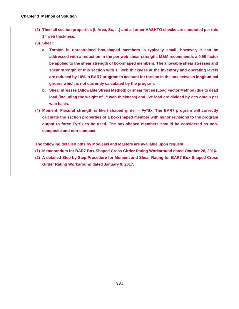
Chapter 3 Method of Solution
3-84
(2) Then all section properties (I, Area, Sx, …) and all other AASHTO checks are computed per this 1” web thickness.
(3) Shear: a. Torsion in unrestrained box-shaped members is typically small; however, it can be
addressed with a reduction in the per web shear strength. M&M recommends a 0.90 factorbe applied to the shear strength of box-shaped members. The allowable shear stresses andshear strength of this section with 1” web thickness at the inventory and operating levelsare reduced by 10% in BAR7 program to account for torsion in the box between longitudinalgirders which is not currently calculated by the program.
b. Shear stresses (Allowable Stress Method) or shear forces (Load Factor Method) due to deadload (including the weight of 1” web thickness) and live load are divided by 2 to obtain perweb basis.
(4) Moment: Flexural strength is like I-shaped girder – Fy*Sx. The BAR7 program will correctly calculate the section properties of a box-shaped member with minor revisions to the program output to force Fy*Sx to be used. The box-shaped members should be considered as non-composite and non-compact.
The following detailed pdfs by Modjeski and Masters are available upon request: (1) Memorandum for BAR7 Box-Shaped Cross Girder Rating Workaround dated October 28, 2016. (2) A detailed Step by Step Procedure for Moment and Shear Rating for BAR7 Box-Shaped Cross
Girder Rating Workaround dated January 9, 2017.

Chapter 3 Method of Solution
3-85
ASSUMPTIONS AND LIMITATIONS
Certain assumptions and limitations of the program are listed here for reference. For details on criteria used in rating
a bridge, refer to the AASHTO Manual.
1. For the bridge types "GFS", "GFF", “GGF”, "TFS", and "TFF", the cross section of the bridge is assumed
symmetrical about the center of floorbeam span.
2. For the bridge types "GFS", "GFF", "TFS", and "TFF", only the left girder or truss is analyzed.
3. Both the Allowable Stress method and Load Factor method are used for ratings of truss members.
4. Only one unit of truck is considered in a lane for a standard loading. Also, when two or more lanes are loaded,
only one unit of truck is considered in each lane.
5. For the bridge types "CTB" and "GGG", the program assumes that all beams or girders are of the same cross
section and the interior beam or girder is critical.
6. For the bridge types "GFS" and "TFS", it is assumed that all stringers are of the same cross section.
7. For the bridge types "GFS", "GFF", "TFS", and "TFF", DL2 is divided by one-half of the total number of stringer
lines and is then applied to each stringer.
8. The program does not check for horizontal shear between the girder and the slab for a composite girder or
encased I-beam.
9. For fatigue life analysis, the maximum and the minimum moments at a detail are calculated from the 10th point
moments by parabolic interpolation. However, the stresses are calculated using the actual section moduli of
the detail.
10. The fatigue life analysis is performed for steel girders and truss members only. The conventional (line girder)
method of structural analysis is used for fatigue life estimations.
11. The program neglects the effects of longitudinal reinforcement in the positive moment region of a continuous
composite girder. However, it assumes that the reinforcement acts compositely with the steel section in the
negative moment region of a continuous composite girder.
12. The program analyzes and rates each section independently, one section at a time, based on the qualification
at that section (compact, braced non-compact, or unbraced non-compact). The program does not consider the
provisions of AASHTO Specifications Article 10.48.3 Transitions. Thus, the section must be either compact or
non-compact. If the program detects one or more non-compact sections, the moment strength of the section,
which would qualify as a compact section by itself, is limited to the moment capacity at first yielding as specified
in AASHTO Specifications Article 10.50(f).
13. If the section is composite and is in the positive moment region, the program always checks the AASHTO
Equation (10-129a) assuming that the maximum flange stress would always exceed the yield stress for a live
load calculated using the rating factor based on moment capacity for compact section. The program assumes
that the maximum flange stress check provision of AASHTO Specifications Article 10.50.1.1.2 is a design check
only and it is not applicable for rating calculations.

Chapter 3 Method of Solution
3-86
14. The program assumes that the existence of the variable web depth for girder, floorbeam, or stringer does not
qualify as a compact section regardless of its section properties and bracing.
15. The program calculates the dead load due to the weight of girder by adding the weights of all ranges entered
by the user and dividing by the sum of span lengths. This dead load is applied as a uniform load to all spans
of a multi-span continuous girder. If the cross section of one span is significantly different than the other spans,
more runs may be required to check for the variation in uniform dead load from one span to other spans.
16. For concentrically loaded bolted and riveted gusset connections, the maximum axial load in each connected
member may be assumed to be distributed equally to all fasteners.
17. The bearing on the fasteners at the joint is not investigated. Only bearing on the connected material of the
gusset plate is investigated.
18. Only the maximum member forces due to dead load and live load plus impact are used to perform the gusset
plate analysis and ratings.
19. BAR 7 does not allow for splice plate data to be entered for gusset plate analysis and rating. If splice plates are
present at gusset plate locations and the Operating Ratings for these locations from the BAR 7 output are less
than “1.00” then PENNDOT’s TGPAR spreadsheet must be used for the analysis of those plate locations. The
splice plate dimensions can be input into the TGPAR spreadsheet in the “optional input information” section of
the input screen of the TGPAR spreadsheet.
20. At gusset plate locations where the member is connected by only one gusset plate and not two gusset plates,
BAR7 cannot be used to obtain accurate Operating Ratings of the gusset plates. BAR7 assumes two gusset
plates are present at each joint and thus divides the forces by 2.

4-1
GETTING STARTED
INSTALLATION
This program is delivered via download from the Department's website. Once payment has been received by
PennDOT you will receive a confirmation e-mail with instructions on how to download the software. The
download file is a self-extracting installation file for the licensed PennDOT engineering software. The
engineering program runs as a 32-bit application and is supported on Windows Vista, Windows 7 (32 and 64
bit versions), Windows 8, and Windows 10 operating systems.
Your license number, license key and registered company name, found in the e-mail received from the
Department, are required to be entered when installing the program and must be entered exactly as shown in
the e-mail. The license number, license key and registered company name will also be needed when
requesting future versions of the program (i.e., enhancements, modifications, or error corrections), and
requesting program support. A backup copy of the program download and e-mail instructions should be made
and used for future installations. You may want to print the software license agreement, record the license
number, license key and registered company name and keep it in a safe place.
To install the program, follow the installation instructions provided with the original e-mail from the Department.
The following files will be installed in the destination folder, which defaults to "C:\Program Files\PennDOT\BAR
v<version number>\" or "C:\Program Files (x86)\PennDOT\BAR7 v<version number>\" for 64-bit operating
systems:
1. BAR7.exe – Executable program (FORTRAN console application).
2. BAR7_DLL.dll – Program Dynamic Link Library.
3. BAR7 Users Manual.pdf – Program User’s Manual (PDF Format).
4. BAR7RevisionRequestForm.dot – Revision Request form (MS WORD template).
5. Microsoft C++ library files if not installed in the C:\WINDOWS\WinSxS folders

Chapter 4 Getting Started
4-2
The program example problem files (BAR7EX*.dat) will be installed in the program example folder, which
defaults to C:\PennDOT\\BAR v<version number> Examples\”. Users must have write access to this folder to
run the input files from this folder.
PREPARING INPUT
The program requires an ASCII input file. The input file consists of a series of data lines. Each data line
consists of a number of fixed length data fields. Chapter 5 of the User’s Manual includes descriptions of the
input and input forms to facilitate data preparation. The input can be created using Engineering Assistant,
described below, or any text editor (such as Notepad).
ENGINEERING ASSISTANT
The Engineering Assistant (EngAsst) is a Windows application developed by the Pennsylvania Department of
Transportation (PENNDOT) to provide a graphical user interface (GUI) for PENNDOT’s engineering programs.
The data for the input to the engineering program is presented in a user-friendly format, reflecting the implied
structure of the data, showing each record type on a separate tab page in the display and showing each field
on each record with a defining label.
With EngAsst the user can create a new input file, modify an existing input file, import input files, run the
associated engineering program and view the output in a Windows environment. The help and documentation
are provided, including text descriptions of each field, relevant images, and extended help text at both the
record/tab level and the field level. Access to all parts of the Engineering Program User’s Manual, where
available, is also provided within EngAsst.
EngAsst is not included with this software. It requires a separate license that can be obtained through the
Department’s standard engineering software licensing procedures. Order forms can be obtained from program
support website at http://penndot.engrprograms.com.
RUNNING THE PROGRAM WITHOUT ENGINEERING ASSISTANT
BAR7 is a FORTRAN console application program. It may be run from a command window, by double-clicking
on the program icon from Windows Explorer, by selecting the shortcut from the Start menu under
Program\PennDOT, or by double-clicking the shortcut icon on the desktop. To run the program in a command
window, the user must specify the directory in which the program has been installed or change to the directory.
The program will first prompt for an input file name, and the user should then enter the appropriate input file
name. The input file must be created before running the program. Next, the program will then prompt for
whether the output should be reviewed on the screen. The user should enter “Y” if the output is to be reviewed

Chapter 4 Getting Started
4-3
on the screen after execution or “N” if the output is not to be reviewed on the screen. The program will then
prompt for the name of the output file in which the output is to be stored, and the user should then enter the
desired output file name. If a file with the specified output file name already exists, the program gives the
option of overwriting the existing file or entering a new output file output file name. If no output file name is
entered, a default output file will be used. The program will then execute.
To cancel the program during execution, press <Ctrl C> or <Ctrl Break>.
When the program execution is completed, the output will be displayed on the screen if the user requested it.
To cancel this review, enter “Q” to quit.
The user can view the output file from within EngAsst or using a text editor (such as Notepad).

Chapter 4 Getting Started
4-4
This page is intentionally left blank.

5-1
INPUT DATA REQUIREMENTS
GENERAL
Twelve input forms (Figure 5.1.1 thru Figure 5.1.12 on pages 5-8 to 5-19) are provided to facilitate data preparation
for execution of this program. Each input form has data lines with appropriate headings. The data that must be
entered depend on the type of bridge (explained earlier) being rated. This section explains each data item.
The following lists the groups of data lines that are required for a given type of bridge.
1. Bridge Type “CPL”, “CSL”, or “CTB”
• Project Identification
• Bridge Cross Section and Loading
• Span Lengths
• Concrete Member Properties
• Stirrup Details (optional)
• Special Live Loading (optional)
• Concentrated Patch Load (optional)
Data Type “C”
• Distributed Patch Load (optional)
Data Type “C”
2. Bridge Type “EIB”
• Project Identification
• Bridge Cross Section and Loading
• Span Lengths
• Concrete Member Properties (optional)
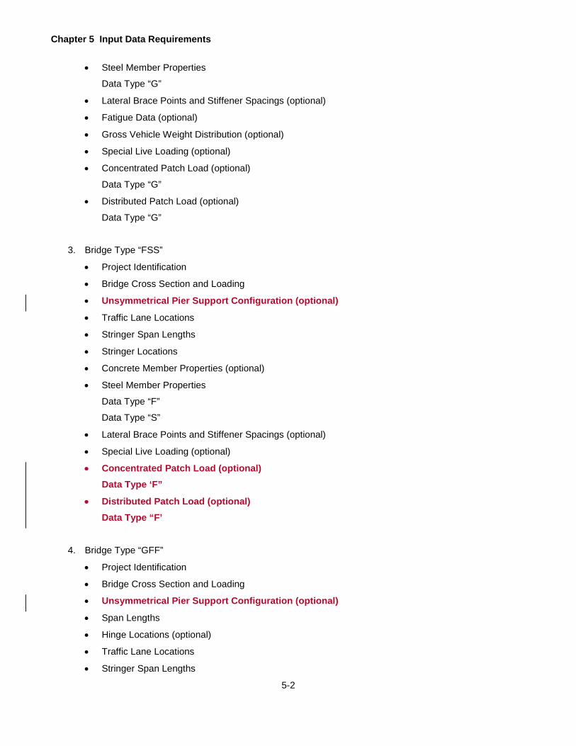
Chapter 5 Input Data Requirements
5-2
• Steel Member Properties
Data Type “G”
• Lateral Brace Points and Stiffener Spacings (optional)
• Fatigue Data (optional)
• Gross Vehicle Weight Distribution (optional)
• Special Live Loading (optional)
• Concentrated Patch Load (optional)
Data Type “G”
• Distributed Patch Load (optional)
Data Type “G”
3. Bridge Type “FSS”
• Project Identification
• Bridge Cross Section and Loading
• Unsymmetrical Pier Support Configuration (optional)
• Traffic Lane Locations
• Stringer Span Lengths
• Stringer Locations
• Concrete Member Properties (optional)
• Steel Member Properties
Data Type “F”
Data Type “S”
• Lateral Brace Points and Stiffener Spacings (optional)
• Special Live Loading (optional)
• Concentrated Patch Load (optional)Data Type ‘F”
• Distributed Patch Load (optional)Data Type “F’
4. Bridge Type “GFF”
• Project Identification
• Bridge Cross Section and Loading
• Unsymmetrical Pier Support Configuration (optional)
• Span Lengths
• Hinge Locations (optional)
• Traffic Lane Locations
• Stringer Span Lengths
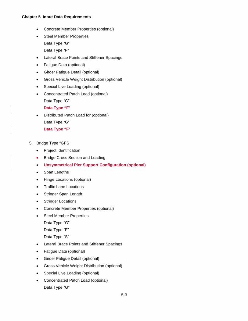
Chapter 5 Input Data Requirements
5-3
• Concrete Member Properties (optional)
• Steel Member Properties
Data Type “G”
Data Type “F”
• Lateral Brace Points and Stiffener Spacings
• Fatigue Data (optional)
• Girder Fatigue Detail (optional)
• Gross Vehicle Weight Distribution (optional)
• Special Live Loading (optional)
• Concentrated Patch Load (optional)
Data Type “G”
Data Type “F’
• Distributed Patch Load for (optional)
Data Type “G”
Data Type “F’
5. Bridge Type “GFS
• Project Identification
• Bridge Cross Section and Loading
• Unsymmetrical Pier Support Configuration (optional)
• Span Lengths
• Hinge Locations (optional)
• Traffic Lane Locations
• Stringer Span Length
• Stringer Locations
• Concrete Member Properties (optional)
• Steel Member Properties
Data Type “G”
Data Type “F”
Data Type “S”
• Lateral Brace Points and Stiffener Spacings
• Fatigue Data (optional)
• Girder Fatigue Detail (optional)
• Gross Vehicle Weight Distribution (optional)
• Special Live Loading (optional)
• Concentrated Patch Load (optional)
Data Type “G”
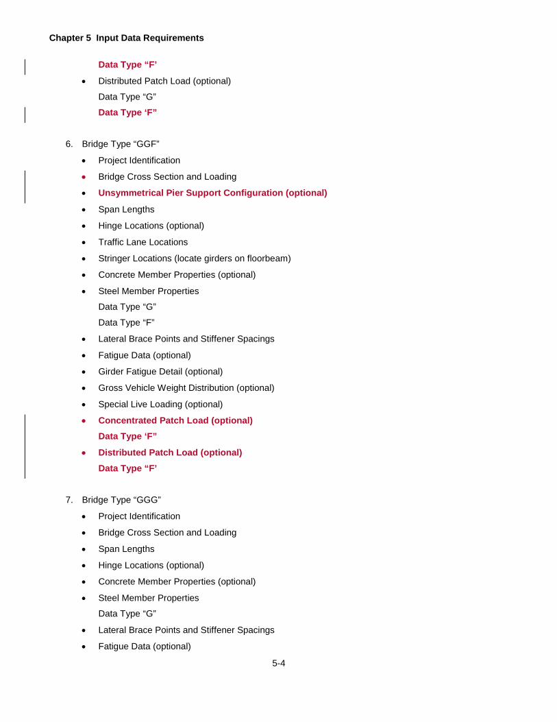
Chapter 5 Input Data Requirements
5-4
Data Type “F’
• Distributed Patch Load (optional)
Data Type “G”
Data Type ‘F”
6. Bridge Type “GGF”
• Project Identification
• Bridge Cross Section and Loading
• Unsymmetrical Pier Support Configuration (optional)
• Span Lengths
• Hinge Locations (optional)
• Traffic Lane Locations
• Stringer Locations (locate girders on floorbeam)
• Concrete Member Properties (optional)
• Steel Member Properties
Data Type “G”
Data Type “F”
• Lateral Brace Points and Stiffener Spacings
• Fatigue Data (optional)
• Girder Fatigue Detail (optional)
• Gross Vehicle Weight Distribution (optional)
• Special Live Loading (optional)
• Concentrated Patch Load (optional) Data Type ‘F”
• Distributed Patch Load (optional) Data Type “F’
7. Bridge Type “GGG”
• Project Identification
• Bridge Cross Section and Loading
• Span Lengths
• Hinge Locations (optional)
• Concrete Member Properties (optional)
• Steel Member Properties
Data Type “G”
• Lateral Brace Points and Stiffener Spacings
• Fatigue Data (optional)
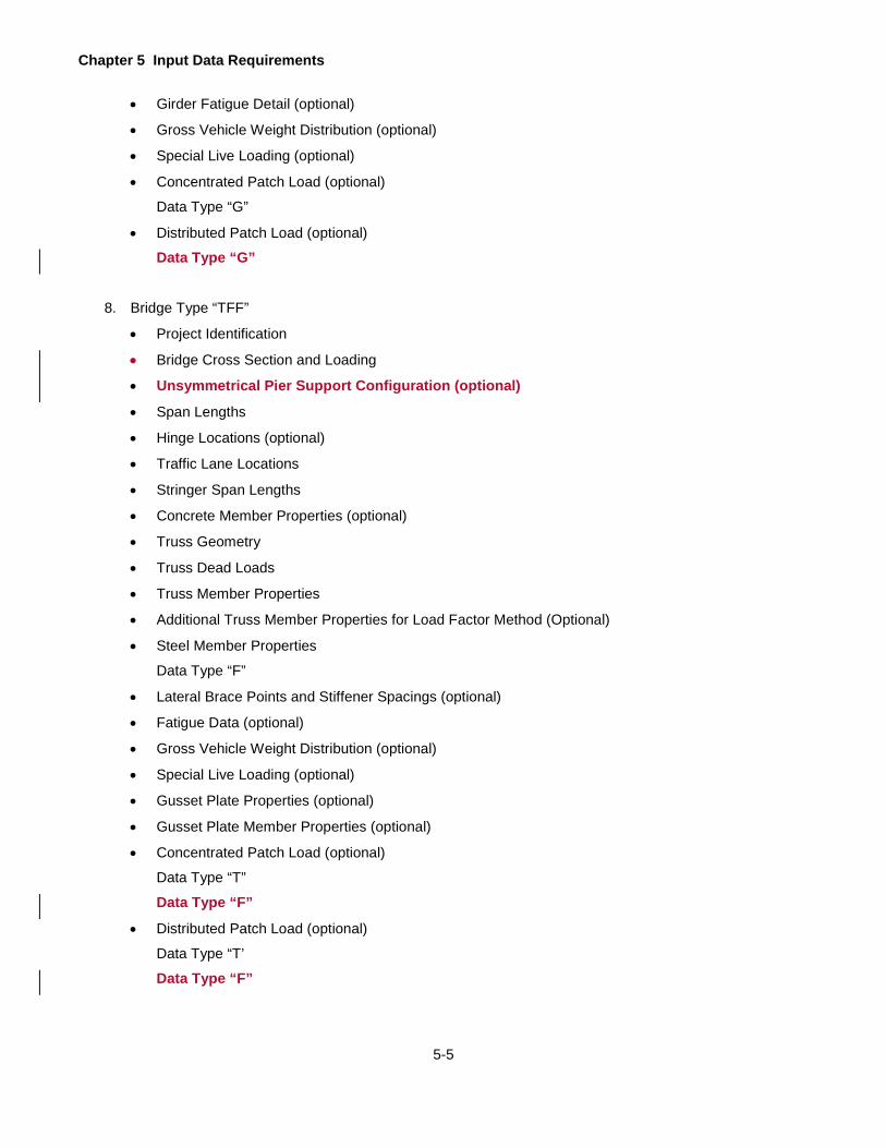
Chapter 5 Input Data Requirements
5-5
• Girder Fatigue Detail (optional)
• Gross Vehicle Weight Distribution (optional)
• Special Live Loading (optional)
• Concentrated Patch Load (optional)
Data Type “G”
• Distributed Patch Load (optional)
Data Type “G”
8. Bridge Type “TFF”
• Project Identification
• Bridge Cross Section and Loading
• Unsymmetrical Pier Support Configuration (optional)
• Span Lengths
• Hinge Locations (optional)
• Traffic Lane Locations
• Stringer Span Lengths
• Concrete Member Properties (optional)
• Truss Geometry
• Truss Dead Loads
• Truss Member Properties
• Additional Truss Member Properties for Load Factor Method (Optional)
• Steel Member Properties
Data Type “F”
• Lateral Brace Points and Stiffener Spacings (optional)
• Fatigue Data (optional)
• Gross Vehicle Weight Distribution (optional)
• Special Live Loading (optional)
• Gusset Plate Properties (optional)
• Gusset Plate Member Properties (optional)
• Concentrated Patch Load (optional)
Data Type “T”
Data Type “F”
• Distributed Patch Load (optional)
Data Type “T’
Data Type “F”
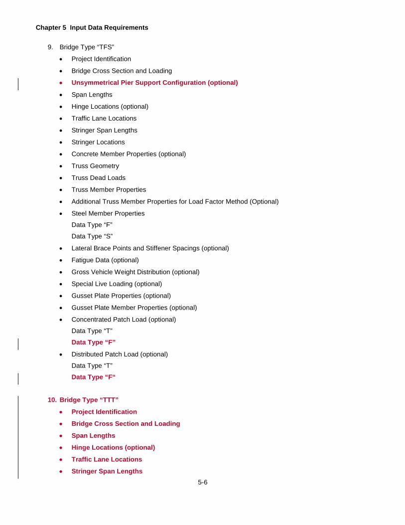
Chapter 5 Input Data Requirements
5-6
9. Bridge Type “TFS”
• Project Identification
• Bridge Cross Section and Loading
• Unsymmetrical Pier Support Configuration (optional)
• Span Lengths
• Hinge Locations (optional)
• Traffic Lane Locations
• Stringer Span Lengths
• Stringer Locations
• Concrete Member Properties (optional)
• Truss Geometry
• Truss Dead Loads
• Truss Member Properties
• Additional Truss Member Properties for Load Factor Method (Optional)
• Steel Member Properties
Data Type “F”
Data Type “S”
• Lateral Brace Points and Stiffener Spacings (optional)
• Fatigue Data (optional)
• Gross Vehicle Weight Distribution (optional)
• Special Live Loading (optional)
• Gusset Plate Properties (optional)
• Gusset Plate Member Properties (optional)
• Concentrated Patch Load (optional)
Data Type “T”
Data Type “F”
• Distributed Patch Load (optional)
Data Type “T”
Data Type “F“
10. Bridge Type “TTT”
• Project Identification
• Bridge Cross Section and Loading
• Span Lengths
• Hinge Locations (optional)
• Traffic Lane Locations
• Stringer Span Lengths

Chapter 5 Input Data Requirements
5-7
• Stringer Locations
• Concrete Member Properties (optional)
• Truss Geometry
• Truss Dead Loads
• Truss Member Properties
• Additional Truss Member Properties for Load Factor Method (Optional)
5.1.1 Input Forms
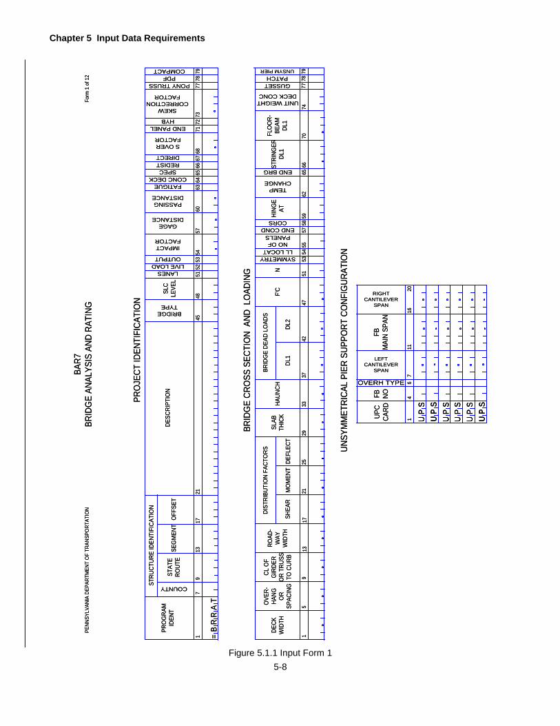
Chapter 5 Input Data Requirements
5-8
PRO
JECT
IDEN
TIFI
CATI
ON
15
DECK
WID
TH
DIST
RIBU
TIO
N FA
CTO
RS
MO
MEN
T
4751
5362
709
1317
21
DEFL
ECT
66
BRID
GE
CRO
SS S
ECTI
ON
AND
LO
ADIN
G
SHEA
R
2529
3342
DL1
F'C
OVE
R-HA
NG OR
SPAC
ING
CL O
FG
IRDE
RO
R TR
USS
TO C
URB
ROAD
-W
AYW
IDTH
SLAB
THIC
KHA
UNCH
37
DL2
BRID
GE
DEAD
LO
ADS
N
SYMMETRYLL LOCAT
NO OFPANELS
END COND
5455
5758
59CORS
HING
EAT
TEMPCHANGE
65
STRI
NGER
DL1
END BRG
PENN
SYLV
ANIA
DEP
ARTM
ENT
OF
TRAN
SPO
RTAT
ION
Form
1 o
f 12
BAR7
BRID
GE
ANAL
YSIS
AND
RAT
ING
FLO
OR-
BEAM
DL1
UNIT WEIGHT DECK CONC
7477
GUSSET 78
PATCH 79
UNSYM PIER
UNSY
MM
ETRI
CAL
PIER
SUP
PORT
CO
NFIG
URAT
ION
COUNTY
17
PRO
GRA
MID
ENT
STRU
CTUR
E ID
ENTI
FICA
TIO
N
STAT
ERO
UTE
DESC
RIPT
ION
4548
5154
5760
67
BRIDGETYPE
913
1721
SEG
MEN
TO
FFSE
T
IMPACTFACTOR
GAGEDISTANCE
PASSINGDISTANCE
63
SLC
LEVE
L
5253
LANESLIVE LOADOUTPUT
FATIGUE 6465
66
CONC DECKSPEC
REDISTDIRECT 68
S OVERFACTOR
SKEW CORRECTION
FACTOR
=B
RR
AT
71
END PANEL 72
HYB 73
PONY TRUSS
77
COMPACTPDF
7879
UPC
CARD
1116
FBM
AIN
SPAN
7
RIGHT CANTILEVER
SPAN
4FB
NO
LEFT CANTILEVER
SPAN
1
OVERH TYPE 620
U
SP
U
SP
U
SP
U
SP
U
SP
U
SP
U
SP
U
SP
U
SP
U
SP
U
SP
U
SP
PRO
JECT
IDEN
TIFI
CATI
ON
15
DECK
WID
TH
DIST
RIBU
TIO
N FA
CTO
RS
MO
MEN
T
4751
5362
709
1317
21
DEFL
ECT
66
BRID
GE
CRO
SS S
ECTI
ON
AND
LO
ADIN
G
SHEA
R
2529
3342
DL1
F'C
OVE
R-HA
NG OR
SPAC
ING
CL O
FG
IRDE
RO
R TR
USS
TO C
URB
ROAD
-W
AYW
IDTH
SLAB
THIC
KHA
UNCH
37
DL2
BRID
GE
DEAD
LO
ADS
N
SYMMETRYLL LOCAT
NO OFPANELS
END COND
5455
5758
59CORS
HING
EAT
TEMPCHANGE
65
STRI
NGER
DL1
END BRG
PENN
SYLV
ANIA
DEP
ARTM
ENT
OF
TRAN
SPO
RTAT
ION
Form
1 o
f 12
BAR7
BRID
GE
ANAL
YSIS
AND
RAT
ING
FLO
OR-
BEAM
DL1
UNIT WEIGHT DECK CONC
7477
GUSSET 78
PATCH 79
UNSYM PIER
UNSY
MM
ETRI
CAL
PIER
SUP
PORT
CO
NFIG
URAT
ION
COUNTY
17
PRO
GRA
MID
ENT
STRU
CTUR
E ID
ENTI
FICA
TIO
N
STAT
ERO
UTE
DESC
RIPT
ION
4548
5154
5760
67
BRIDGETYPE
913
1721
SEG
MEN
TO
FFSE
T
IMPACTFACTOR
GAGEDISTANCE
PASSINGDISTANCE
63
SLC
LEVE
L
5253
LANESLIVE LOADOUTPUT
FATIGUE 6465
66
CONC DECKSPEC
REDISTDIRECT 68
S OVERFACTOR
SKEW CORRECTION
FACTOR
=B
RR
AT
71
END PANEL 72
HYB 73
PONY TRUSS
77
COMPACTPDF
7879
UPC
CARD
1116
FBM
AIN
SPAN
7
RIGHT CANTILEVER
SPAN
4FB
NO
LEFT CANTILEVER
SPAN
1
OVERH TYPE 620
U
SP
U
SP
U
SP
U
SP
U
SP
U
SP
Figure 5.1.1 Input Form 1
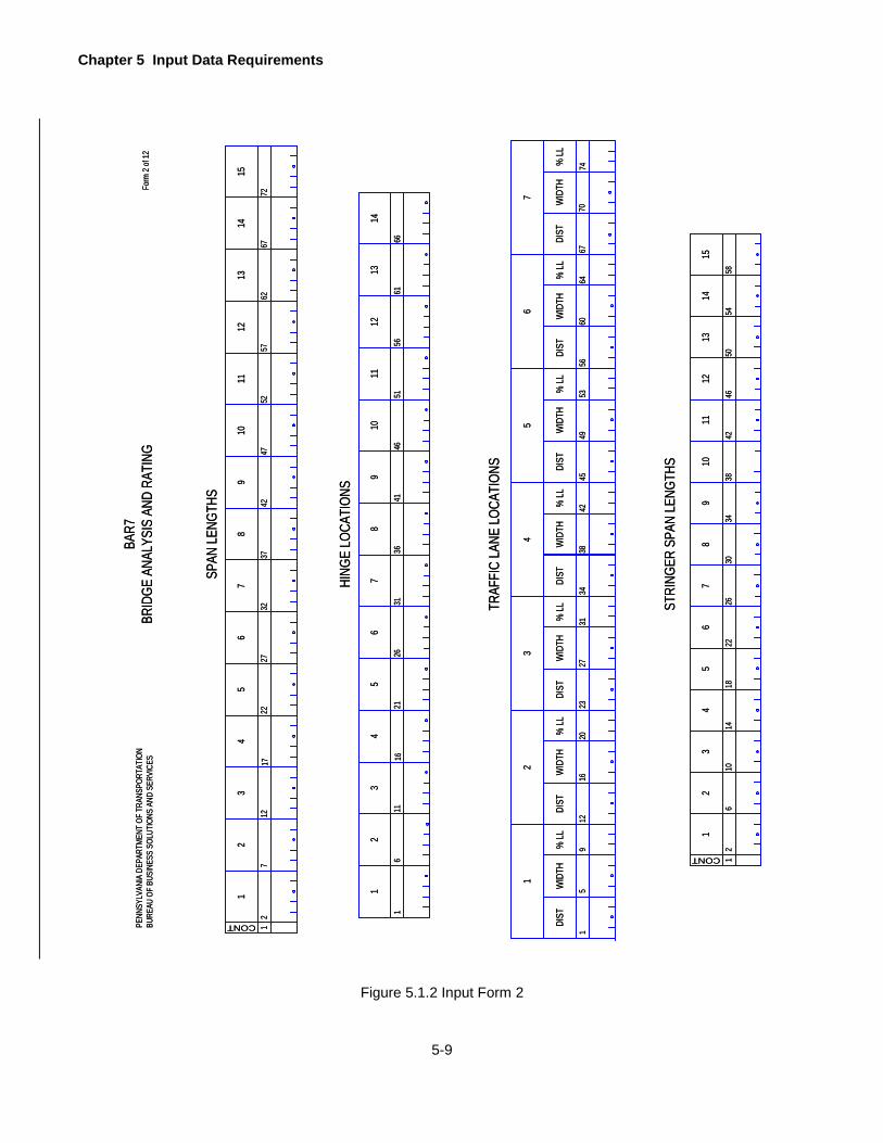
Chapter 5 Input Data Requirements
5-9
Form
2 of
12
12
19
CONT
712
1722
3
SPAN
LENG
THS
24
2732
3742
67
85
4752
5762
6772
1011
1213
1415
1
19
611
1621
3
HING
E LO
CATI
ONS
24
2631
3641
67
85
4651
5661
66
1011
1213
14
TRAF
FIC
LANE
LOCA
TION
S
12
111
CONT
610
1418
3
STRI
NGER
SPA
N LE
NGTH
S
24
2630
3442
65
4650
5458
1213
14
22
78
9
38
1015
BAR7
BRID
GE A
NALY
SIS
AND
RATI
NGPE
NNSY
LVAN
IA D
EPAR
TMEN
T OF
TRA
NSPO
RTAT
ION
BURE
AU O
F BU
SINE
SS S
OLUT
IONS
AND
SER
VICE
S
19
5
1
DIST
WID
TH%
LL
1220
16
2
DIST
WID
TH%
LL
2331
27
3
DIST
WID
TH%
LL
3442
38
4
DIST
WID
TH%
LL
4553
49
5
DIST
WID
TH%
LL
5664
60
6
DIST
WID
TH%
LL%
LLW
IDTH
DIST
6770
74
7
Figure 5.1.2 Input Form 2
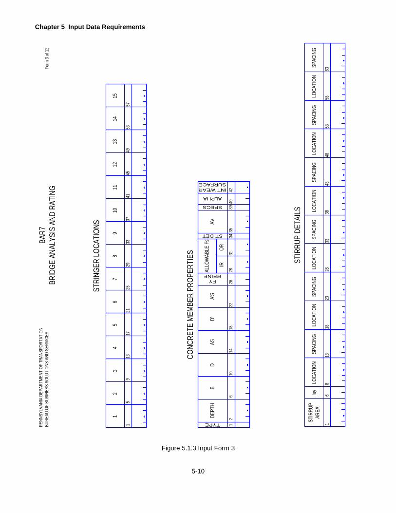
Chapter 5 Input Data Requirements
5-10
12DE
PTH
TYPE
610
1418
D
CONC
RETE
MEM
BER
PROP
ERTI
ES
BAS
2628
3440
A'S
D'
1STIR
RUP
AREA
68
13
LOCA
TION
STIR
RUP
DETA
ILS
fsySP
ACIN
G
22FY
REINFALL
OWAB
LE F
sAV
31
IROR
ST DET 3539
SPECS
ALPHA
42
INT WEARSURFACE
1823
LOCA
TION
SPAC
ING
2833
LOCA
TION
SPAC
ING
3843
LOCA
TION
SPAC
ING
4853
LOCA
TION
SPAC
ING
5863
LOCA
TION
SPAC
ING
BAR7
BRID
GE A
NALY
SIS
AND
RATI
NGPE
NNSY
LVAN
IA D
EPAR
TMEN
T OF
TRA
NSPO
RTAT
ION
BURE
AU O
F BU
SINE
SS S
OLUT
IONS
AND
SER
VICE
SFo
rm 3
of 12
1
111
59
1317
3
STRI
NGER
LOCA
TION
S
24
2129
3741
78
96
4549
5357
1213
1415
5
2533
10
Figure 5.1.3 Input Form 3
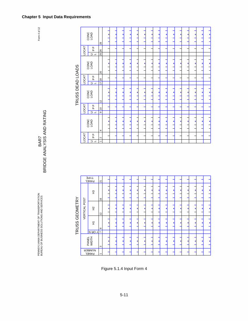
Chapter 5 Input Data Requirements
5-11
13P
AN
EL
WID
TH
PANELNUMBER
712
16
Y OR N
TRU
SS
GE
OM
ETR
Y
H3
218
H1
H2
VE
RTI
CA
L P
OS
T
PANELTYPE
12P
P
TRU
SS
DE
AD
LO
AD
S
4
U LLOC
AT
CO
NC
LOA
D
910P
P
12
U LLOC
AT
CO
NC
LOA
D
1718P
P
20
U LLOC
AT
CO
NC
LOA
D
2526P
P
28
U LLOC
AT
CO
NC
LOA
D
BA
R7
BR
IDG
E A
NA
LYS
IS A
ND
RA
TIN
GFo
rm 4
of 1
2P
EN
NS
YLV
AN
IA D
EP
AR
TME
NT
OF
TRA
NS
PO
RTA
TIO
NB
UR
EA
U O
F B
US
INE
SS
SO
LUTI
ON
S A
ND
SE
RV
ICE
S
Figure 5.1.4 Input Form 4

Chapter 5 Input Data Requirements
5-12
BAR7
BRID
GE A
NALY
SIS
AND
RATI
NGPE
NNSY
LVAN
IA D
EPAR
TMEN
T OF
TRA
NSPO
RTAT
ION
BURE
AU O
F BU
SINE
SS S
OLUT
IONS
AND
SER
VICE
SFo
rm 5
of 1
2
TRUS
S M
EMBE
R PR
OPER
TIES
12P
P
4
U M LMEM
BER
ID
712
GROS
SAR
EACO
MPR
1723
MOM
ENT
OFIN
ERTI
AIx
26
L
30
FY
ECCENTRICITY
5
U M LP
P
NET
AREA
TENS
ION
FLAN
GEW
IDTH
C
CATEGORY
GROS
SAR
EATE
NSIO
NFU
3337
4143
46
SECT
ION
MOD
ULUS
Sxc
MOM
ENT
OF
INER
TIA
Iyc
TORS
ION
INER
TIA
Jxy
5154
65
DEPT
H
71
UNSU
PPFL
ANGE
LENG
THL
59
MOM
ENT
OFIN
ERTI
AIy
8077
Figure 5.1.5 Input Form 5
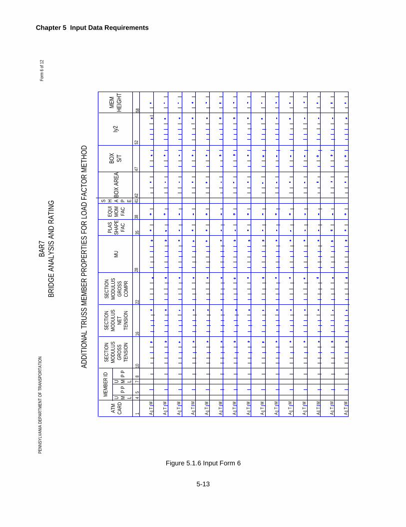
Chapter 5 Input Data Requirements
5-13
BAR7
BRID
GE A
NALY
SIS
AND
RATI
NGPE
NNSY
LVAN
IA D
EPAR
TMEN
T OF
TRA
NSPO
RTAT
ION
Form
6 o
f 12
ADDI
TION
AL T
RUSS
MEM
BER
PROP
ERTI
ES F
OR L
OAD
FACT
OR M
ETHO
D
45P
P
7
U M LMEM
BER
ID
1016
SECT
ION
MOD
ULUS
GR
OSS
TENS
ION
2228
MU
8
U M LP
P
SECT
ION
MOD
ULUS
NET
TENS
ION
3538
4142
EQUI
M
OM
FAC
PLAS
SH
APE
FAC
S H A P E
SECT
ION
MOD
ULUS
GR
OSS
COM
PR
ATM
CA
RD
1 A
MT
A
MT T
AM
TA
M
TA
M
TA
M
TA
M
TA
M
TA
M
TA
M
TA
M
TA
M
TA
M
TA
M
TA
M
BOX
AREA
BOX
S/T
Iy2
5258
47
MEM
HEIG
HT
Figure 5.1.6 Input Form 6

Chapter 5 Input Data Requirements
5-14
12
STEE
L M
EMBE
R PR
OPE
RTIE
S
38
WF
BEA
MM
OF
IO
R A
NGLE
VERT
LEG
1621
WF
BEA
MAR
EAO
R A
NGLE
HORZ
LEG
26
FLAN
GE
WID
TH
31
FLAN
GE
OR
ANG
LETH
ICK
VARIES
RANG
E
WF
BEA
MO
R W
EBPL
ATE
DEPT
H
WEB
THIC
KTH
ICK
WID
TH
G F OR SSPAN NO
9
SECT TYPE
3237
4246
THIC
KW
IDTH
5155
60
COMPOSITE 6164
6770
75
TOP
PLA
TEBO
TTO
M P
LATE
FYFY TO
PFY BO
TCG TO
PCG BO
T
HYBR
IDUN
SYM
MET
RICA
L
BAR7
BRID
GE
ANAL
YSIS
AND
RAT
ING
PENN
SYLV
ANIA
DEP
ARTM
ENT
OF
TRAN
SPO
RTAT
ION
BURE
AU O
F BU
SINE
SS S
OLU
TIO
NS A
ND S
ERVI
CES
Form
7 o
f 12 S H A P E 80
Figure 5.1.7 Input Form 7
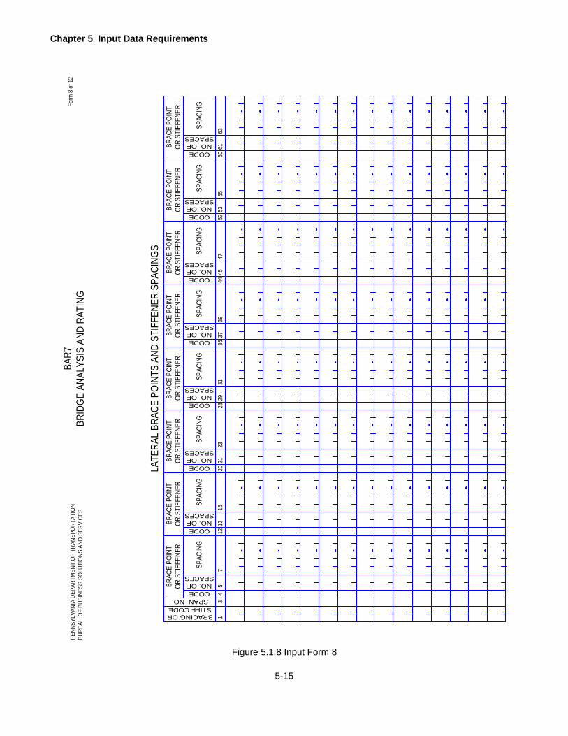
Chapter 5 Input Data Requirements
5-15
13
LATE
RAL
BRAC
E PO
INTS
AND
STI
FFEN
ER S
PACI
NGS
4
BRAC
E PO
INT
OR S
TIFF
ENER
75
CODE
SPAC
ING
BRACING ORSTIFF CODESPAN NO.
1215
13CODE
2023
21CODE
2831
29CODENO. OF
SPACES
3639
37CODE
4447
45CODE
5255
53CODE
6063
61CODE
SPAC
ING
SPAC
ING
SPAC
ING
SPAC
ING
SPAC
ING
SPAC
ING
SPAC
ING
BRAC
E PO
INT
OR S
TIFF
ENER
BRAC
E PO
INT
OR S
TIFF
ENER
BRAC
E PO
INT
OR S
TIFF
ENER
BRAC
E PO
INT
OR S
TIFF
ENER
BRAC
E PO
INT
OR S
TIFF
ENER
BRAC
E PO
INT
OR S
TIFF
ENER
BRAC
E PO
INT
OR S
TIFF
ENER
NO. OFSPACES
NO. OFSPACES
NO. OFSPACES
NO. OFSPACES
NO. OFSPACES
NO. OFSPACES
NO. OFSPACES
BAR7
BRID
GE A
NALY
SIS
AND
RATI
NGFo
rm 8
of 1
2PE
NNSY
LVAN
IA D
EPAR
TMEN
T OF
TRA
NSPO
RTAT
ION
BURE
AU O
F BU
SINE
SS S
OLUT
IONS
AND
SER
VICE
S
Figure 5.1.8 Input Form 8

Chapter 5 Input Data Requirements
5-16
12
DIS
TFR
OM
CL
BR
G
SPAN NO
712
14
GIR
DER
FAT
IGU
E D
ETAI
L
1
GR
OSS
VEH
ICLE
WEI
GH
T D
ISTR
IBU
TIO
N
6
MIN
1115
MAX
GR
OSS
VEH
ICLE
WEI
GH
T
1923
2AX
LE
NO
OF
SIN
GLE
UN
IT T
RU
CKS
1
YEAR
BUIL
T
59
1317
ADTT
FATI
GU
E D
ATA
YEAR
OR
GF
YEAR
2529
34
ADTT
2130
NO OFGVWD
YEAR
OR
GF
ADTT
PREV
IOU
S C
OU
NT
REC
ENT
CO
UN
TFU
TUR
E C
OU
NT
R OR N
ON
ELA
NE
DIS
TRFA
CTO
R
DIS
TFR
OM
BOTT
OM
CATEGORY
1921
DIS
TFR
OM
BOTT
OM
CATEGORY26
28
DIS
TFR
OM
BOTT
OM
CATEGORY
33
DIS
TFR
OM
BOTT
OM
CATEGORY
3AX
LE4
AXLE
2731
3AX
LE
NO
OF
SIN
GLE
UN
IT T
RU
CKS
4AX
LE5
OR
>AX
LE
BAR
7BR
IDG
E AN
ALYS
IS A
ND
RAT
ING
PEN
NSY
LVAN
IA D
EPAR
TMEN
T O
F TR
ANSP
OR
TATI
ON
BUR
EAU
OF
BUSI
NES
S SO
LUTI
ON
S AN
D S
ERVI
CES
Form
9 o
f 12
Figure 5.1.9 Input Form 9

Chapter 5 Input Data Requirements
5-17
12
SP LL NO
45
914
CO
NC
LOAD
MO
MEN
T
LAN
E LO
ADIN
G
UN
IFO
RM
LAN
ELO
AD
2226
19
GAGEDISTANCE
NUMBEROF AXLES3% INCR
CO
NC
LOAD
SHEA
R
PASSINGDISTANCE
25
VARY LAST
MAX
AXLE
DIS
T
1
TRU
CK
LOAD
8
AXLE
LOAD
5DIS
TAX
LELO
AD
12
DIS
TAX
LELO
AD
15
DIS
TAX
LELO
AD
19
DIS
TAX
LELO
AD
22
DIS
TAX
LELO
AD
40
DIS
TAX
LELO
AD
47
DIS
TAX
LELO
AD
54
DIS
T
SPEC
IAL
LIVE
LO
ADIN
G
Not
e:
Both
the
Lane
Loa
d an
d th
e Tr
uck
Load
mus
t be
desc
ribed
as
a se
t for
eac
h of
the
spec
ial l
ive
load
s.
2629
3336
4350
BAR
7BR
IDG
E AN
ALYS
IS A
ND
RAT
ING
PEN
NSY
LVAN
IA D
EPAR
TMEN
T O
F TR
ANSP
OR
TATI
ON
BUR
EAU
OF
BUSI
NES
S SO
LUTI
ON
S AN
D S
ERVI
CES
Fo
rm 1
0 of
12
Figure 5.1.10 Input Form 10
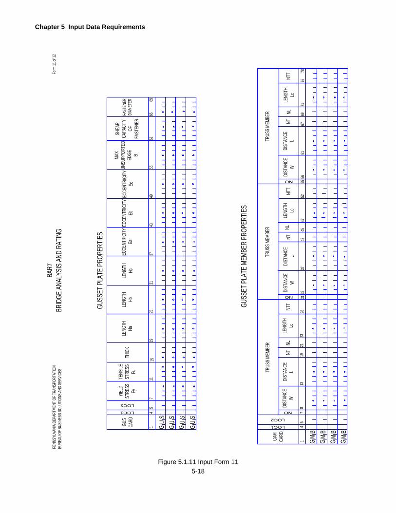
Chapter 5 Input Data Requirements
5-18
LOC1
14
GUS
CARD
YIELD
ST
RESS
Fy
4349
615
1115
19
TENS
ILE
STRE
SSFu
THIC
K
MAX
UNSU
PPOR
TED
EDGE B
SHEA
R CA
PACI
TYOF
FAST
ENER
GUSS
ET PL
ATE P
ROPE
RTIES
1GAM
CARD
TRUS
S MEM
BER
694
519
21
NT
GUSS
ET PL
ATE M
EMBE
R PR
OPER
TIES
2331
5566FA
STEN
ERDI
AMET
ER
DIST
ANCE
WDI
STAN
CEL
GU
S
Form
11 of
12BA
R7BR
IDGE
ANAL
YSIS
AND
RATIN
G
LOC2
7
LENG
THHa
LENG
THHb
LENG
THHc
ECCE
NTRI
CITY
EaEC
CENT
RICI
TYEb
ECCE
NTRI
CITY
Ec
2531
37
GM
B
LOC1
LOC2
8
NL
SU
G
LENG
THLc
NO 713
4345
NT
47
DIST
ANCE
WDI
STAN
CEL
32
NLLE
NGTH
Lc
37
NO
5561
76
NT 67
DIST
ANCE
WDI
STAN
CEL
NL
52
NO
LENG
THLc
TRUS
S MEM
BER
TRUS
S MEM
BER
G GGB BB
MMM
SU
GS
UG
NTT
2871
NTT
NTT
5678
69
PENN
SYLV
ANIA
DEPA
RTME
NT O
F TRA
NSPO
RTAT
ION
BURE
AU O
F BUS
INES
S SOL
UTIO
NS AN
D SE
RVIC
ES
Figure 5.1.11 Input Form 11
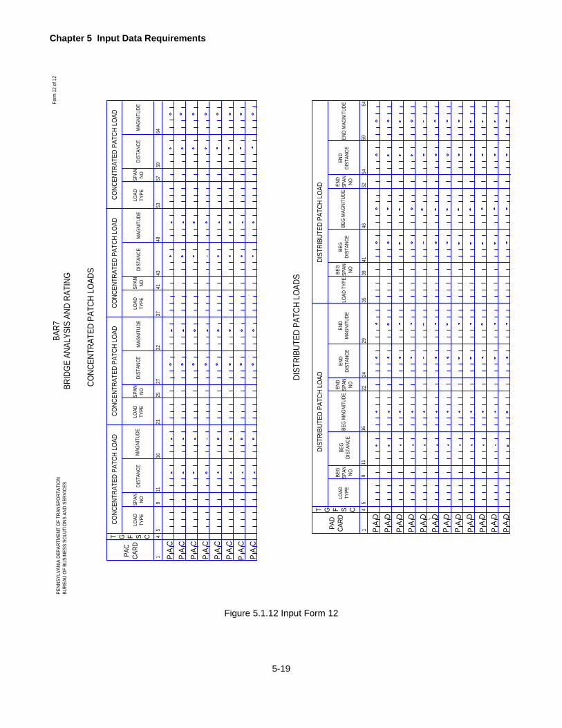
Chapter 5 Input Data Requirements
5-19
CONC
ENTR
ATED
PAT
CH L
OADS
DIST
RIBU
TED
PATC
H LO
ADS
PENN
SYLV
ANIA
DEP
ARTM
ENT
OF T
RANS
PORT
ATIO
NBU
REAU
OF
BUSI
NESS
SOL
UTIO
NS A
ND S
ERVI
CES
Form
12
of 1
2BA
R7BR
IDGE
ANA
LYSI
S AN
D RA
TING
LOAD
TY
PE
15
PAC
CARD
4148
5911
1621
SPAN
NO
DIST
ANCE
DIST
ANCE
64MAG
NITU
DE
PA
C
9
MAG
NITU
DELO
AD
TYPE
MAG
NITU
DEDI
STAN
CEM
AGNI
TUDE
2532
37
CA
PC
AP
CA
P
CCC
AAA
PPP
CA
P
1PAD
CARD
416
22
BEG
MAG
NITU
DE
24
BEG
SPAN
NO
BEG
DIST
ANCE
PA
D9
END
SPAN
NO
END
DIST
ANCE
1146
41
BEG
DIST
ANCE
52
LOAD
TYP
EBE
G SP
AN
NO
35
BEG
MAG
NITU
DEEN
D SP
AN
NO
3959EN
D M
AGNI
TUDE
54
DIST
RIBU
TED
PATC
H LO
AD
P PPA A
D DA
29
END
M
AGNI
TUDE
DDP
AP
A
DPPPPP P
DDDDD
AAAAA A
LOAD
TY
PE
SPAN
NO
DIST
ANCE
27
LOAD
TY
PESP
AN
NO
43
DIST
RIBU
TED
PATC
H LO
AD
END
DIST
ANCE
CONC
ENTR
ATED
PAT
CH L
OAD
CONC
ENTR
ATED
PAT
CH L
OAD
CONC
ENTR
ATED
PAT
CH L
OAD
LOAD
TY
PESP
AN
NO
CONC
ENTR
ATED
PAT
CH L
OAD
5357
4T G F S C
5
D
T G F S C64
Figure 5.1.12 Input Form 12

Chapter 5 Input Data Requirements
5-20
PROJECT IDENTIFICATION
PROGRAM IDENT
Enter “=BRRAT” to identify the data for this program. The program checks these characters and will
terminate the execution if the proper combination of characters is not present. The message “IDENT
ERROR – EXECUTION TERMINATED” will appear.
STRUCTURE IDENTIFICATION
Enter a 14-digit Structure Identification number the same as that used in the Bridge Management System
(BMS). This number is comprised of 4 data items for each bridge. The 4 data items are COUNTY, STATE
ROUTE, SEGMENT and OFFSET. Entering this data correctly and saving the BAR7 input data, as
permanent members in an Engineering Dialog Input Library will enable BAR7 data to be integrated into the
Automated Permit Routing/Analysis System (APRAS).
DESCRIPTION
Enter a description of the bridge or problem being analyzed. Any alphanumeric characters, up to a
maximum of 24, can be entered. Use the first four characters to enter APRAS Span ID.
BRIDGE TYPE
Enter the type of bridge being rated. Enter one of the following 12 codes:
"CPL” - for a precast concrete slab bridge
"CSL” - for a concrete slab bridge
"CTB" - for a concrete T -beam bridge
"EIB” - for an encased I-beam bridge
"FSS” - for a floorbeam-stringer type bridge with no truss or main girder
"GFF" - for a girder-floorbeam type bridge (no stringers)
"GFS" - for a girder-floorbeam-stringer type bridge
"GGF” - for a multigirder bridge on floorbeams that are supported on columns
"GGG" - for a multigirder bridge
"TFF" - for a truss-floorbeam type bridge (no stringers)
"TFS" - for a truss-floorbeam-stringer type bridge
"TTT” - for a truss bridge (no floorbeam and stringer analysis)
SLC LEVEL
Enter a code, as explained below, if the Safe Load Capacity (SLC) of the bridge is desired and it is to be
printed in the Rating Summary. Leave this blank if the SLC value is not desired.
Enter the stress or strength level to which the bridge may be allowed to carry the load to determine its Safe
Load Capacity. The level can be expressed as a percent of either the Inventory Capacity (Stress or
Strength) or the Operating Capacity (Stress or Strength).

Chapter 5 Input Data Requirements
5-21
If the SLC level is expressed as a percentage increase of the Inventory Capacity, enter "I" followed by a
two-digit number which indicates the percent of stress or strength above the Inventory Capacity. For
example, enter I25 if the stress or strength level can be 25 percent above the Inventory Capacity to
determine the Safe Load Capacity of the bridge.
If the SLC level is expressed as a percent of Operating Capacity, enter the letter "0" followed by a two-digit
number that indicates the percent of Operating Capacity that can be used in determining the Safe Load
Capacity of the bridge. For example, enter 085 if the stress or strength level to determine the Safe Load
Capacity of the bridge can be 85 percent of the Operating Capacity.
If a value is entered here, also enter an "L" for LANES (explained next) and appropriate values in the Traffic
Lane Locations line. The program uses these to calculate SLC in the Rating Summary.
If a value is entered here, but LANES (explained next) is entered as "D" or blank, the program does not
calculate SLC and does not print SLC value in the Rating Summary.
If the SLC level is expresses as a percent of Operating Rating Factor, enter the letter “A” followed by a two-
digit number which indicate the percent of Operating Rating Factor that can be used in determining the
Safe Load Capacity of the bridge. For example, enter A85 if the stress or strength level to determine the
Safe Load Capacity of the bridge can be 85 percent of the Operating Rating Factor.
LANES
For the bridge types of "CPL", "CSL", "CTB", "EIB", and "GGG" leave this blank and go to the next item.
For all other bridge types of "FSS", "GFF", "GFS", "GGF", "TFF", "TFS", and “TTT’, enter "D" or "L"
depending on the following:
If the ratings are to be calculated based on the number of possible design lanes and the stress or strength
levels as defined by AASHTO Manual, enter "D". For a normal rating analysis or design check, use this
option. When this option is used, the program checks all possible numbers and positions of the design lane
locations on the bridge and all load positions within a lane in accordance with AASHTO Manual.
If the ratings are to be calculated based on the fixed number and positions of traffic lanes as defined by the
user, enter “L” here and enter TRAFFIC LANE LOCATIONS described later. When this option is used, the
program only checks the load possible within the fixed lane locations. This option should be used only for
a special analysis, e.g. checking a safe passage of a permit load on a bridge. When this option is used, the
program may only identify the critical rating for one component of a bridge (e.g. truss member or floorbeam).
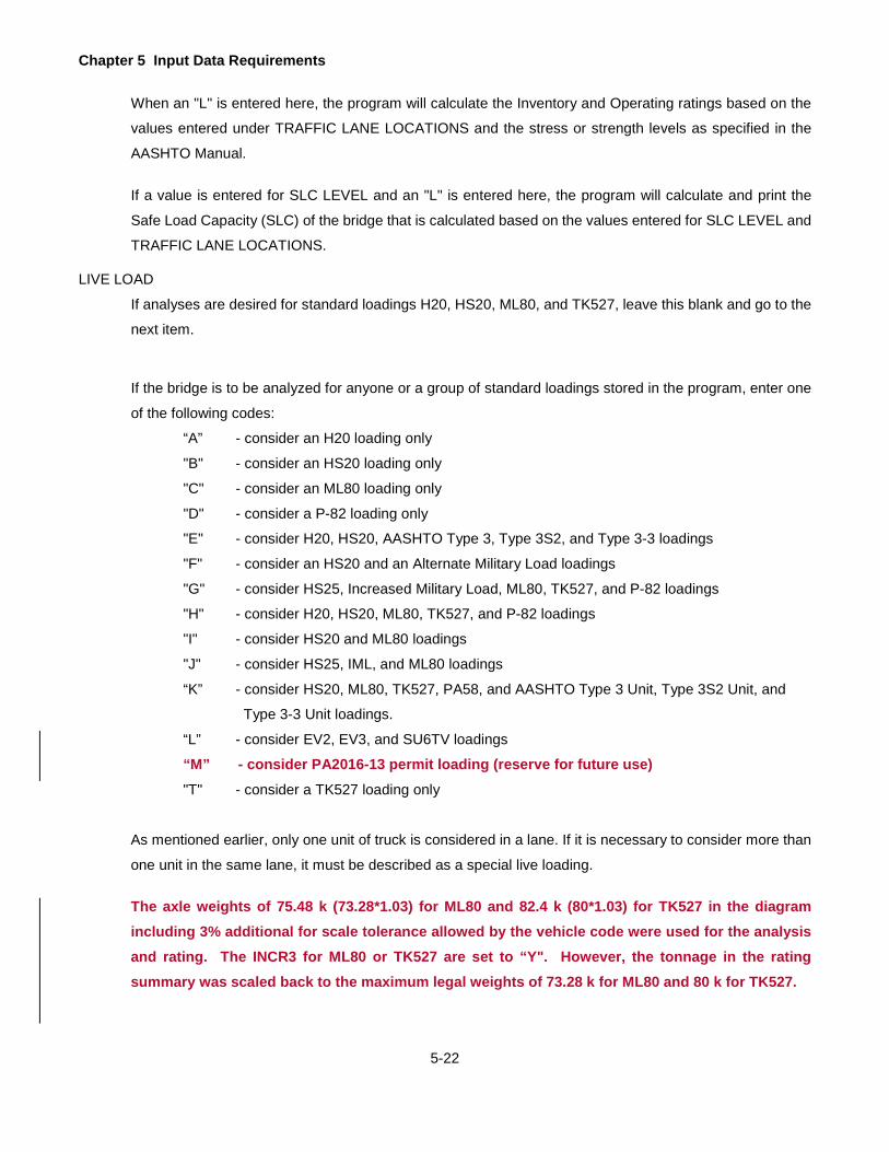
Chapter 5 Input Data Requirements
5-22
When an "L" is entered here, the program will calculate the Inventory and Operating ratings based on the
values entered under TRAFFIC LANE LOCATIONS and the stress or strength levels as specified in the
AASHTO Manual.
If a value is entered for SLC LEVEL and an "L" is entered here, the program will calculate and print the
Safe Load Capacity (SLC) of the bridge that is calculated based on the values entered for SLC LEVEL and
TRAFFIC LANE LOCATIONS.
LIVE LOAD
If analyses are desired for standard loadings H20, HS20, ML80, and TK527, leave this blank and go to the
next item.
If the bridge is to be analyzed for anyone or a group of standard loadings stored in the program, enter one
of the following codes:
“A” - consider an H20 loading only
"B" - consider an HS20 loading only
"C" - consider an ML80 loading only
"D" - consider a P-82 loading only
"E" - consider H20, HS20, AASHTO Type 3, Type 3S2, and Type 3-3 loadings
"F" - consider an HS20 and an Alternate Military Load loadings
"G" - consider HS25, Increased Military Load, ML80, TK527, and P-82 loadings
"H" - consider H20, HS20, ML80, TK527, and P-82 loadings
"I" - consider HS20 and ML80 loadings
"J" - consider HS25, IML, and ML80 loadings
“K” - consider HS20, ML80, TK527, PA58, and AASHTO Type 3 Unit, Type 3S2 Unit, and
Type 3-3 Unit loadings.
“L” - consider EV2, EV3, and SU6TV loadings “M” - consider PA2016-13 permit loading (reserve for future use)
"T" - consider a TK527 loading only
As mentioned earlier, only one unit of truck is considered in a lane. If it is necessary to consider more than
one unit in the same lane, it must be described as a special live loading.
The axle weights of 75.48 k (73.28*1.03) for ML80 and 82.4 k (80*1.03) for TK527 in the diagram including 3% additional for scale tolerance allowed by the vehicle code were used for the analysis and rating. The INCR3 for ML80 or TK527 are set to “Y". However, the tonnage in the rating summary was scaled back to the maximum legal weights of 73.28 k for ML80 and 80 k for TK527.

Chapter 5 Input Data Requirements
5-23
If the bridge is to be analyzed for any special live loadings that cannot be defined by any of the standard
live loadings stored in the program, enter the number of special loadings (up to a maximum of eight for
which the data is provided later). When a number is entered here, the analyses for standard loadings
defined above are not provided. The sets of data for special live loadings entered later should correspond
to the number entered here.
OUTPUT
Enter one of the options given in Figure 5.2.1 on page 5-24 depending on the level and type of output
desired.
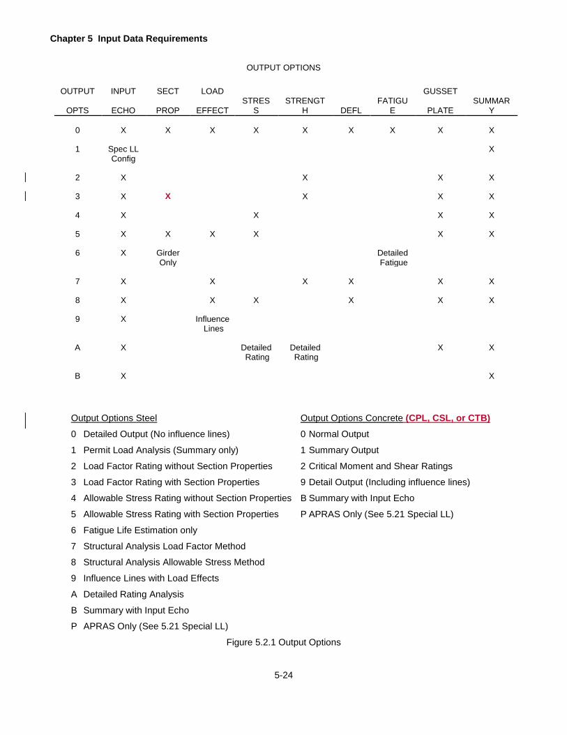
Chapter 5 Input Data Requirements
5-24
OUTPUT OPTIONS
OUTPUT INPUT SECT LOAD GUSSET
OPTS ECHO PROP EFFECT STRES
S STRENGT
H DEFL FATIGU
E PLATE SUMMAR
Y
0 X X X X X X X X X
1 Spec LL X Config
2 X X X X
3 X X X X X
4 X X X X
5 X X X X X X
6 X Girder Detailed Only Fatigue
7 X X X X X X
8 X X X X X X
9 X Influence Lines
A X Detailed Detailed X X Rating Rating
B X X
Output Options Steel Output Options Concrete (CPL, CSL, or CTB) 0 Detailed Output (No influence lines) 0 Normal Output
1 Permit Load Analysis (Summary only) 1 Summary Output
2 Load Factor Rating without Section Properties 2 Critical Moment and Shear Ratings
3 Load Factor Rating with Section Properties 9 Detail Output (Including influence lines)
4 Allowable Stress Rating without Section Properties B Summary with Input Echo
5 Allowable Stress Rating with Section Properties P APRAS Only (See 5.21 Special LL)
6 Fatigue Life Estimation only
7 Structural Analysis Load Factor Method
8 Structural Analysis Allowable Stress Method
9 Influence Lines with Load Effects
A Detailed Rating Analysis
B Summary with Input Echo
P APRAS Only (See 5.21 Special LL)
Figure 5.2.1 Output Options
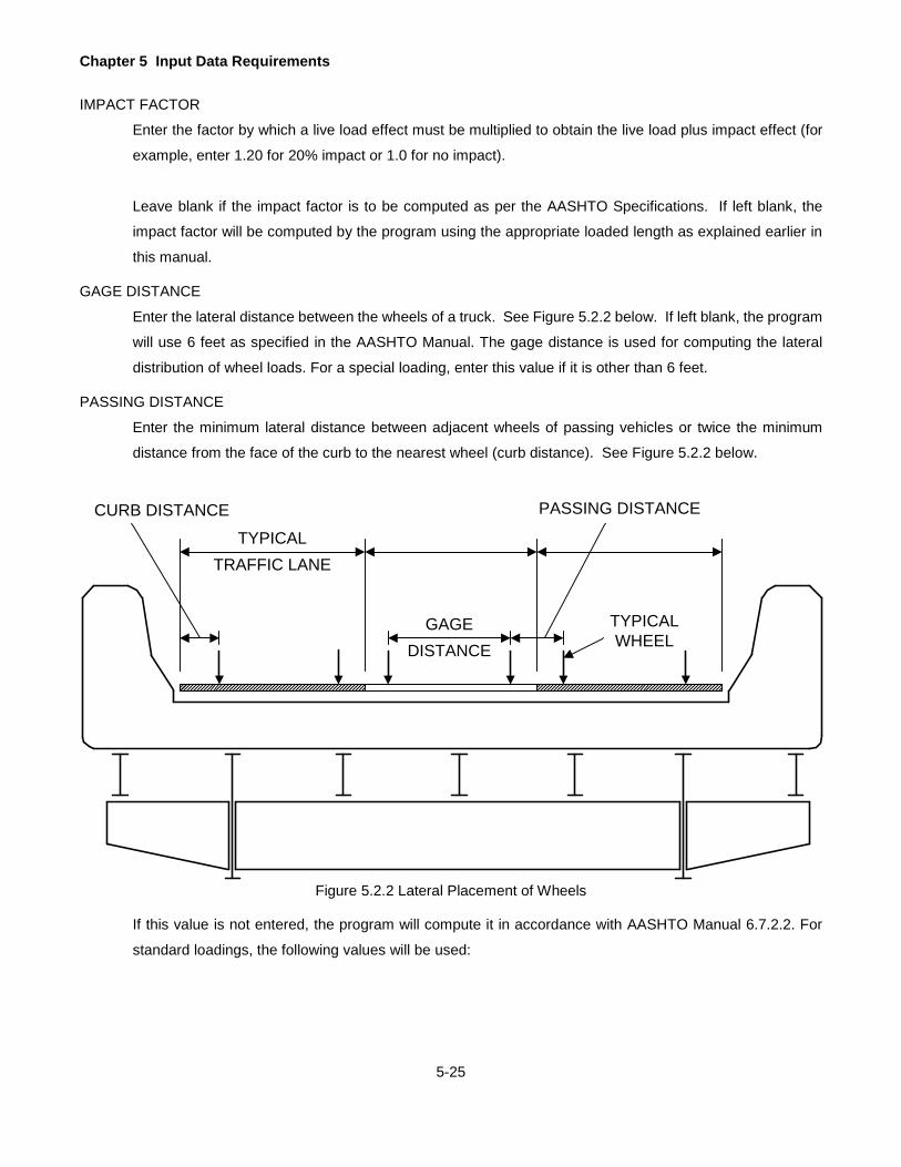
Chapter 5 Input Data Requirements
5-25
IMPACT FACTOR
Enter the factor by which a live load effect must be multiplied to obtain the live load plus impact effect (for
example, enter 1.20 for 20% impact or 1.0 for no impact).
Leave blank if the impact factor is to be computed as per the AASHTO Specifications. If left blank, the
impact factor will be computed by the program using the appropriate loaded length as explained earlier in
this manual.
GAGE DISTANCE
Enter the lateral distance between the wheels of a truck. See Figure 5.2.2 below. If left blank, the program
will use 6 feet as specified in the AASHTO Manual. The gage distance is used for computing the lateral
distribution of wheel loads. For a special loading, enter this value if it is other than 6 feet.
PASSING DISTANCE
Enter the minimum lateral distance between adjacent wheels of passing vehicles or twice the minimum
distance from the face of the curb to the nearest wheel (curb distance). See Figure 5.2.2 below.
Figure 5.2.2 Lateral Placement of Wheels
If this value is not entered, the program will compute it in accordance with AASHTO Manual 6.7.2.2. For
standard loadings, the following values will be used:
CURB DISTANCE
TYPICALTRAFFIC LANE
GAGEDISTANCE
TYPICALWHEEL
PASSING DISTANCE
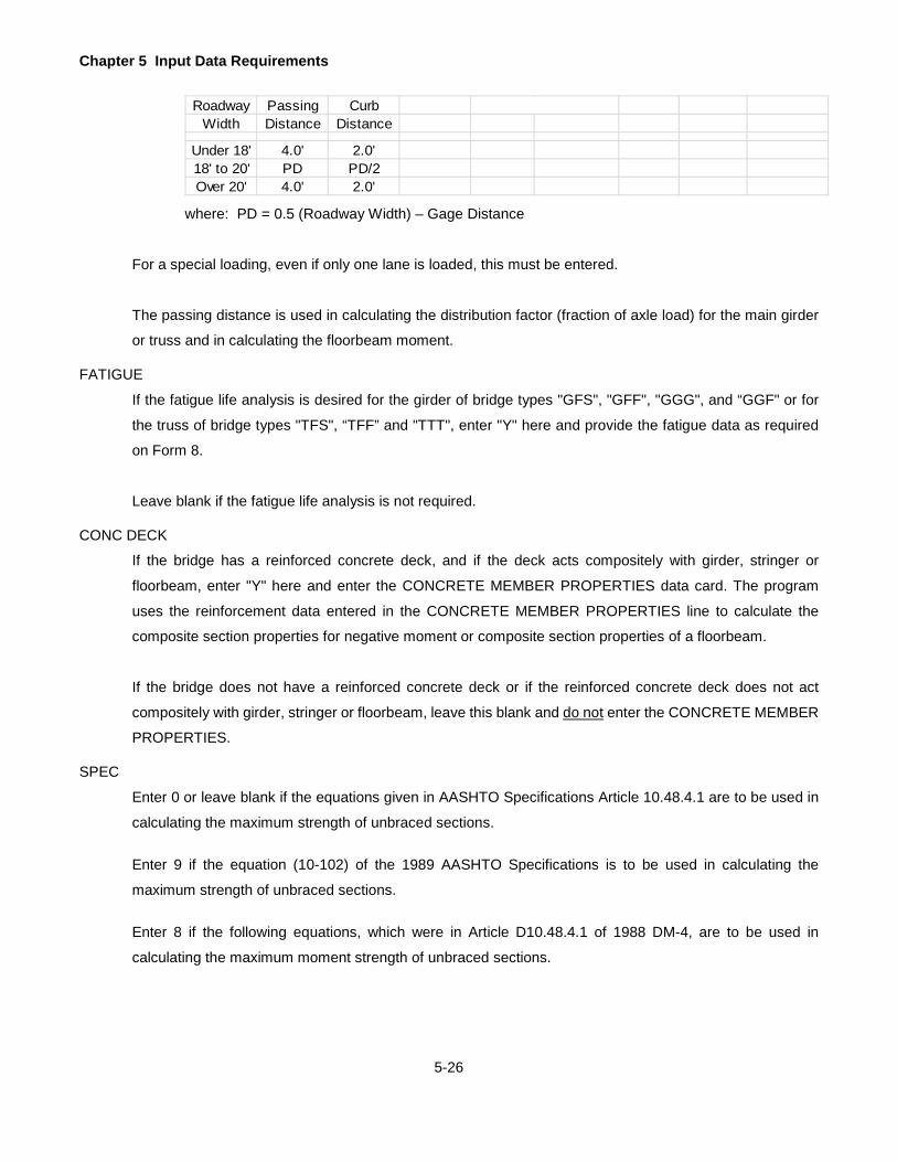
Chapter 5 Input Data Requirements
5-26
where: PD = 0.5 (Roadway Width) – Gage Distance
For a special loading, even if only one lane is loaded, this must be entered.
The passing distance is used in calculating the distribution factor (fraction of axle load) for the main girder
or truss and in calculating the floorbeam moment.
FATIGUE
If the fatigue life analysis is desired for the girder of bridge types "GFS", "GFF", "GGG", and “GGF" or for
the truss of bridge types "TFS", “TFF” and "TTT", enter "Y" here and provide the fatigue data as required
on Form 8.
Leave blank if the fatigue life analysis is not required.
CONC DECK
If the bridge has a reinforced concrete deck, and if the deck acts compositely with girder, stringer or
floorbeam, enter "Y" here and enter the CONCRETE MEMBER PROPERTIES data card. The program
uses the reinforcement data entered in the CONCRETE MEMBER PROPERTIES line to calculate the
composite section properties for negative moment or composite section properties of a floorbeam.
If the bridge does not have a reinforced concrete deck or if the reinforced concrete deck does not act
compositely with girder, stringer or floorbeam, leave this blank and do not enter the CONCRETE MEMBER
PROPERTIES.
SPEC
Enter 0 or leave blank if the equations given in AASHTO Specifications Article 10.48.4.1 are to be used in
calculating the maximum strength of unbraced sections.
Enter 9 if the equation (10-102) of the 1989 AASHTO Specifications is to be used in calculating the
maximum strength of unbraced sections.
Enter 8 if the following equations, which were in Article D10.48.4.1 of 1988 DM-4, are to be used in
calculating the maximum moment strength of unbraced sections.
Roadway Passing CurbWidth Distance Distance
Under 18' 4.0' 2.0'18' to 20' PD PD/2Over 20' 4.0' 2.0'
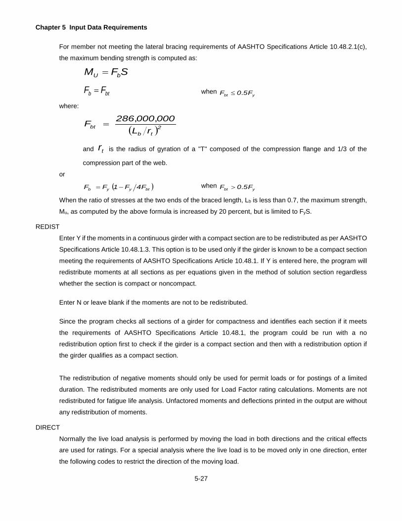
Chapter 5 Input Data Requirements
5-27
For member not meeting the lateral bracing requirements of AASHTO Specifications Article 10.48.2.1(c),
the maximum bending strength is computed as:
SFM bU =
btb FF = when ybt F50F .≤
where:
( )2tb
bt rL000000286F ,,
=
and tr is the radius of gyration of a "T" composed of the compression flange and 1/3 of the
compression part of the web.
or
( )btyyb F4F1FF −= when ybt F50F .>
When the ratio of stresses at the two ends of the braced length, Lb is less than 0.7, the maximum strength,
Mu, as computed by the above formula is increased by 20 percent, but is limited to FyS.
REDIST
Enter Y if the moments in a continuous girder with a compact section are to be redistributed as per AASHTO
Specifications Article 10.48.1.3. This option is to be used only if the girder is known to be a compact section
meeting the requirements of AASHTO Specifications Article 10.48.1. If Y is entered here, the program will
redistribute moments at all sections as per equations given in the method of solution section regardless
whether the section is compact or noncompact.
Enter N or leave blank if the moments are not to be redistributed.
Since the program checks all sections of a girder for compactness and identifies each section if it meets
the requirements of AASHTO Specifications Article 10.48.1, the program could be run with a no
redistribution option first to check if the girder is a compact section and then with a redistribution option if
the girder qualifies as a compact section.
The redistribution of negative moments should only be used for permit loads or for postings of a limited
duration. The redistributed moments are only used for Load Factor rating calculations. Moments are not
redistributed for fatigue life analysis. Unfactored moments and deflections printed in the output are without
any redistribution of moments.
DIRECT
Normally the live load analysis is performed by moving the load in both directions and the critical effects
are used for ratings. For a special analysis where the live load is to be moved only in one direction, enter
the following codes to restrict the direction of the moving load.

Chapter 5 Input Data Requirements
5-28
Enter “L” for moving the live load from left to right.
Enter “R” for moving the live load from right to left.
Leave blank to move the loads both ways.
S OVER FACTOR
For a bridge type "FSS”, “GFS", or "TFS", if the user wants the program to calculate the distribution factor
for moment for an interior stringer, enter the denominator part of the wheel load distribution factor formula
(S/Factor) given in AASHTO Specifications Table 3.23.1. This value varies from 3.75 to 5.5 depending on
the kind of floor and the number of lanes for which the bridge is designed.
The program will use the following formula to calculate the live load distribution factor for moment (DFM)
and will apply to an interior stringer.
=
FACTOROVERSSPACING
21DFM
For a given interior stringer, the SPACING is taken as the average of two adjacent spacings calculated from
the Stringer Locations entered by the user.
If the value of SPACING, is greater than the limit given in AASHTO Specifications Table 3.23.1, then the
stringer must be analyzed separately with the distribution factor entered based on AASHTO Specifications
Table 3.23.1, footnote f.
For bridge types "FSS", "GFS", or “TFS", if a value of S OVER FACTOR is not entered in the Project Identification line, both the exterior and interior stringers will use the DFS_M. If a value of S OVER FACTOR is entered in the Project Identification line, the exterior stringers will use the DFS_M and the interior stringers will use the value calculated using S OVER FACTOR. When only one stringer entered in the Steel Member Properties line, this stringer will use the DFS_M, regardless of the interior or exterior stringer.
END PANEL
Enter “Y” if AASHTO Specifications Article 10.48.8.1 Equation (10-113) is to be used to calculate the shear
capacity in the end panel. This allows the shear capacity to include post buckling strength. Enter “N” or
leave blank if post buckling strength is not to be included in the end panel and the program is to use
AASHTO Specifications Article 10.48.8.3 Equation (10-118).
HYB
Enter “Y” if AASHTO Specifications Article 10.48.8.1 Equation (10-113) is to be used to calculate the shear
capacity for transversely stiffened hybrid girders. Enter “N” or leave blank to use AASHTO Specifications
Article 10.53.1.4 Equation (10-149).

Chapter 5 Input Data Requirements
5-29
SKEW CORRECTION FACTOR
Enter the skew correction factor to account for increased shear due to skew. This factor is applied to the
distribution factor used to compute live load shear. Refer to the AASHTO LRFD Section 4.6.2.2.3c for bridge
types of “CTB” and “GGG”.
The default of skew correction factor is 1.
PONY TRUSS STABILITY CHECK
Enter “Y” if a Pony Truss Stability Check is to be calculated. Enter “N” or leave it blank if no Pony Truss
Stability Check is to be done. If “Y” is entered Additional Truss Properties must be entered for analysis to
done.
PDF OUTPUT
Enter “Y” to produce a PDF file of the output in addition to the filename.OUT file. Enter “N” to produce only
the standard filename.OUT file.
COMPACT Enter “Y” or leave blank to produce rating summary using the all-or-none compact section requirements. Enter “N” to produce the rating summary not using the all-or-none compact section requirements.
Chapter 5 Input Data Requirements
5-30
BRIDGE CROSS SECTION AND LOADING
Refer to Figure 5.3.1 on page 5-32 for input items on this line.
DECK WIDTH
Enter the total width of the deck including the sidewalk and parapet - feet. The program uses this dimension
to compute the dead load due to the deck. This must be entered for the bridge types “CPL”, "FSS", "GFF”,
“GFS", "GGF", "TFF", "TFS", and ”TTT”.
Leave blank for the bridge types "CSL", "CTB", "EIB", and "GGG".
OVERHANG OR SPACING
For the bridge types "FSS", "GFS", "GFF", "GGF", "TFF", "TFS", and ”TTT”, enter the length of the
floorbeam overhang that extends outside the main girder, truss or support - feet. When OVERHANG is
entered for the above bridge types, the program assumes that the floorbeam is continuous across the main
girders, trusses or supports, i.e. the portions of the floorbeam inside and outside of the main girder, truss
or support are connected by a tie plate and the overhang acts as a cantilever. Leave this blank if the
continuity of the floorbeam is not to be considered.
If a value is entered here, the program will calculate the dead load due to the weight of overhang and add
it to the value of DL1 entered for the girder. If the continuity of the floorbeam is not considered and if there
are brackets supporting the overhang portion of the deck include the weight of brackets in DL1 entered for
the main girder.
For the bridge types "CTB", "EIB" and "GGG", enter the width of deck slab carried by the beam or girder -
feet. By entering the appropriate width and live load distribution factors (explained later), either an interior
or an exterior beam or girder can be analyzed.
Leave blank for bridge types "CPL" and "CSL".
CL OF GIRDER OR TRUSS TO CURB
Enter the distance from the centerline of the main girder, truss or support to the inside face of the curb -
feet. This distance is negative if the girder, truss or support is placed inside the roadway and it is positive if
the girder, truss or support is placed outside of the roadway. This must be entered for bridge types "FSS",
"GFF", "GFS", "GGF", "TFF", "TFS", and ”TTT”.
Leave blank for bridge types "CPL", "CSL", "CTB", "EIB", and "GGG".
NOTE: To accommodate negative values less than -9.99, omit the minus sign and use an alphabetic
character in the first column of this item as follows: Enter A for a value -10.00 thru -19.99, B for a value -

Chapter 5 Input Data Requirements
5-31
20.00 thru -29.99, C for a value -30.00 thru -39.99, etc. As an example, to enter the negative distance -
17.55, code A755 for this input item. The negative distance –22.25 should be coded B225.
ROADWAY WIDTH
Enter the width of the roadway from curb to curb - feet. The program uses this dimension together with the
above CL OF GIRDER OR TRUSS TO CURB dimension to compute the center-to-center spacing of main
girders or trusses.
If the girder, truss or support is placed inside the roadway, then ROADWAY WIDTH = SPACING BETWEEN
MAIN GIRDERS OR TRUSSES + 2.0*absolute value of (CL OF GIRDER OR TRUSS TO CURB)
If the girder, truss or support is placed outside the roadway, then ROADWAY WIDTH = SPACING
BETWEEN MAIN GIRDERS OR TRUSSES - 2.0*absolute value of (CL OF GIRDER OR TRUSS TO
CURB)

Chapter 5 Input Data Requirements
5-32
Figure 5.3.1 Bridge Cross Section
ROADWAY WIDTHROADWAY WIDTH
DECK WIDTH
L OF GIRDERC
TO CURB (-)
OVERHANG
SLAB
THICKNESS
ROADWAY WIDTH
DECK WIDTH
SPACING (TYP.)SPACING (TYP.)
Chapter 5 Input Data Requirements
5-33
DISTRIBUTION FACTORS
After the consideration of the number of lanes and multi-lane reduction factor, enter the live load
distribution factor expressed as the fraction of an axle (lane) load to be applied to:
(1) The precast concrete slab (C) of the bridge type “CPL”.
(2) A one-foot strip of a concrete slab (C) of the bridge type "CSL".
(3) The T -beam (C) of the bridge type "CTB".
(4) The encased I-beam (G) of the bridge type "EIB".
(5) The floorbeam (F) of the bridge type "GFF" or "TFF".
(6) The stringer (S) of the bridge types "FSS", "GFS", and "TFS".
(7) The girder (G) of the bridge types "GGG" and "GGF".
The AASHTO Specifications refer to this distribution as a fraction of a wheel load to be applied. The axle
(lane) load distribution factor is equal to one-half of the wheel load distribution factor.
Enter the appropriate distribution factor depending on whether an interior or an exterior beam or girder is
to be analyzed. The program can analyze only one type of beam or girder at a time.
If the values are left blank for a precast concrete slab bridge (bridge type "CPL"), the distribution factors
are computed by the program as per AASHTO Specifications Article 3.23.4.3.
If the values are left blank for a concrete slab bridge (bridge type "CSL"), the distribution factors are
computed by the program as per AASHTO Specifications Article 3.24.3.2.
The distribution factors for the main girder of the bridge type "GFF" or "GFS" and the truss of the bridge
type "TFS", ”TFF”, or "TTT" are computed by the program from the bridge cross section data with the
consideration of the number of traffic lanes and multi-lane reduction factor.
The following three (3) types of distribution factors are to be entered:
SHEAR, DFS_R
The live load distribution factor to be used in computing reactions at end supports and shears at sections
adjacent to end supports for a concrete T-beam, a precast slab bridge, a one-foot strip of a concrete slab
bridge, or a stringer. Refer to 1996 AASHTO Specifications Article 3.23.1. Enter one-half of the wheel load
distribution factor.
If this value is left blank for a concrete slab bridge (bridge type "CSL"), this factor is calculated by the
program as per 1996 AASHTO Specifications Article 3.24.3.2 assuming a non-skewed bridge.
If this value is left blank for a precast concrete slab bridge (bridge type "CPL"), this factor is calculated by
the program as per 1996 AASHTO Specifications Article 3.23.4.3 assuming a non-skewed bridge.

Chapter 5 Input Data Requirements
5-34
MOMENT, DFS_M
The live load distribution factor to be used in computing moments in a one-foot strip of a concrete slab
bridge or in stringers and longitudinal beams (see 1996 AASHTO Specifications Table 3.23.1 Distribution of Wheel Loads in Longitudinal Beams).
If this value is left blank for a precast concrete slab bridge (bridge type "CPL"), this factor is calculated by
the program as per the 1996 AASHTO Specifications Article 3.23.4.3 assuming a non-skewed bridge.
If this value is left blank for a concrete slab bridge (bridge type "CSL"), this factor is calculated by the
program as per 1996 AASHTO Specifications Article 3.24.3.2 assuming a non-skewed bridge.
For the floorbeam member (F) of the bridge type “GFF’ and “TFF” where the floor is directly supported on floorbeams, enter here one-half of the wheel load distribution factor (i,e. the axle (lane) load distribution factor) specified in 1996 AASHTO Specifications Table 3.23.3.1 Distribution of Wheel Loads in Transverse Beams or leave blank if the program should calculate the reactions (distribution factor x axle loads) at each floorbeam by the influence line method based on the flooring to act as a simple span or continuous span (refer to footnote of 1996 AASHTO Specifications Table 3.23.3.1).
For the stringer (S) of the bridge types "FSS", "GFS", or “TFS", if a value of S OVER FACTOR is not entered in the Project Identification line, both the exterior and interior stringers will use the DFS_M. If a value of S OVER FACTOR is entered in the Project Identification line, the exterior stringers will use the DFS_M and the interior stringers will use the value calculated using S OVER FACTOR. When only one stringer entered in the Steel Member Properties line, this stringer will use the DFS_M, regardless of the interior or exterior stringer
For the girder (G) of the bridge type "GGF", enter the distribution factor for the critical girder, either
interior or exterior. The program will determine the critical girder based on the inputted girder spacings. It
may take an additional run of the program if the results of the first run show that the critical girder is different
than what was assumed for this factor. Please note that program will copy this value to DL1ST.
DEFLECT, DFS_D
The distribution factor to be used in computing live load deflections in a one-foot strip of a concrete slab
bridge or in stringers and longitudinal beams. This is equal to the number of design lanes divided by the
number of beams.
If this value is left blank for a precast concrete slab bridge (bridge type "CPL"), this factor is calculated by
the program as per AASHTO Specifications Article 3.23.4.3 assuming a non-skewed bridge.

Chapter 5 Input Data Requirements
5-35
If this value is left blank for a concrete slab bridge (bridge type "CSL"), this factor is calculated by the
program as per AASHTO Specifications Article 3.24.3.2 assuming a non-skewed bridge.
SLAB THICK
For steel bridges, concrete T -beam bridges and encased I-beam bridges, enter the total thickness of the
concrete slab - inches. The total thickness will be used to compute the dead load due to the slab. For
concrete T-beam bridges and composite sections, one-half inch will be subtracted from the total thickness
to find the effective slab thickness.
For steel bridges with other types of floors, such as timber or steel grid, do not enter a slab thickness. The
dead load due to the floor must be included in the DEAD LOADS DL2.
HAUNCH
The distance from the top of the girder to the bottom of the slab – inches. This value is negative if the
bottom of the slab is below the top of the girder. Leave blank if no haunch is to be considered for the
composite section. For the bridge type "EIB", enter this distance without a negative sign. The program will
assume a negative value for type "EIB". Entering a negative HAUNCH for bridge type "EIB" will indicate
that the top of beam is below the bottom of the slab.
When the haunch changes due to camber or variable top flange thickness, enter the minimum haunch so
that the analysis is conservative. If a section becomes critical and the actual haunch at that section is
greater than the minimum, the program can be rerun using the actual haunch to analyze that particular
section.
BRIDGE DEAD LOADS - DL1, DL2
Enter the dead loads acting on the bridge.
For the purpose of analyzing a beam type member, such as a girder, stringer, T -beam or slab, the dead
loads are divided into two categories: DL1 and DL2.
The dead loads acting on the truss are entered as panel point loads under TRUSS DEAD LOADS described
later in this section.
The following two types of loads are entered depending on the type of bridge.
DL1
DL1 are dead loads that are applied to the girder or beam. DL1 includes dead loads due to the weight of
beam, girder, slab, haunch, permanent formwork, stringers, floorbeams, diaphragms, bracings, stiffeners,
(sidewalk, if poured integrally with the deck), and other hardware attached to the beam. The weight of
Chapter 5 Input Data Requirements
5-36
sidewalk and sidewalk live load should also be included for bridge types “GFS” and “GFF” where the
sidewalk is cantilevered out from the outside of the girder.
Enter the dead load due to the weight of diaphragms, haunch, permanent formwork, bracings, and stiffeners
and or other hardware attached to the girder or beam. Include the weight of sidewalk and sidewalk live load
for bridge types “GFS” and “GFF” where the sidewalk is cantilevered out from the outside of the girder. Do
not include the weight of beam, girder, slab, stringers and floorbeams. These weights are computed by the
program. Also, do not include the weight of the truss. The dead loads acting on the truss are entered
separately under TRUSS DEAD LOADS.
Enter this load as follows depending on the type of bridge:
1. For the bridge types "CPL", “CTB”, "EIB", and "GGG", enter the load per girder or beam per foot length
- kips/ft.
2. For the bridge type "CSL", enter the load per square foot of the slab - kips/ft2.
3. For the bridge type “FSS”, leave it blank. The DL1 dead loads applied to the floorbeams are entered
separately under FLOORBEAM DL1. The DL1 dead loads applied to the stringers are entered
separately under STRINGER DL1.
4. For the bridge types "GFF" and "GFS", compute the load per foot of length of the bridge for the entire
cross section of the bridge, divide by two and enter the value - kips/ft. The program applies this DL1 dead load to the left main girder only. The DL1 dead loads applied to the floorbeams are entered separately under FLOORBEAM DL1. The DL1 dead loads applied to the stringers are entered separately under STRINGER DL1.
5. For the bridge type “GGF", enter the load per girder or beam per foot length - kips/ft. The program applies this load to the critical stringer above the floorbeam GGF has multiple beams (or stringers) supported by the floorbeams below. Since the girder analysis subroutine is used instead of the stringer analysis subroutine, DL1 entered by the user was used and STRINGER DL1 was not used in the girder analysis subroutine. The DL1 dead loads applied to the floorbeams are entered separately under FLOORBEAM DL1.
6. For the bridge types “TFF”, “TFS”, and “TTT”, leave it blank. The DL1 dead loads applied to the truss
are entered separately under TRUSS DEAD LOADS. The DL1 dead loads applied to the floorbeams are entered separately under FLOORBEAM DL1. The DL1 dead loads applied to the stringers are entered separately under STRINGER DL1.
DL2
DL2 are dead loads that are applied to the deck. DL2 includes dead loads due to the future wearing surface,
weight of parapet, (sidewalk, if placed on top of the deck), median, railing, steel grid flooring, timber flooring,
other structure permanently attached to the deck and the sidewalk live load. Program does not compute any DL2 load.

Chapter 5 Input Data Requirements
5-37
Enter the dead load due to the future wearing surface, weight of parapet, sidewalk, median, railing, steel
grid flooring, timber flooring, other structures permanently attached to the deck, and the sidewalk live load.
If the bridge has a concrete deck and a sidewalk, consider the weight of sidewalk only due to the additional
thickness (total thickness at sidewalk less the SLAB THICKness entered earlier) of the deck at the sidewalk.
If the bridge has a sidewalk and the sidewalk live load is applicable, compute the total width (include both
if the bridge has sidewalks on both sides) of sidewalk and multiply by the per square foot value of the
sidewalk live load given in the AASHTO Specifications.
Enter this load as follows depending on the type of bridge:
1. For the bridge types, "CPL”, “CTB”, “EIB”, "GGF", and "GGG", enter the load per girder or beam per
foot length - kips/ft.
2. For the bridge type "CSL", enter the load per square foot of the slab - kips/ft2.
3. For the bridge type “FSS”, enter the load per foot of the floorbeam –kips/ft2. For end floorbeams, the
load is computed based on the area bounded by half the span length of the end span. For interior
floorbeams the load is computed based on the area bounded by average of the sum of two adjacent
interior span lengths.
4. For the bridge types "GFF" and "GFS", compute the load per foot of length of the bridge for the entire
cross section of the bridge, divide by two and enter the value - kips/ft. For the bridge types "GFF" and
"GFS", the program applies this load to the left main girder. DL2 acting on the stringer and floorbeam
is computed by the program from the value entered here. 5. For the bridge types "TFF", "TFS", and “TTT”, compute the load per foot of length of the bridge
for the entire cross section of the bridge, divide by two and enter the value - kips/ft. The DL2 dead loads acting on the truss are entered separately under TRUSS DEAD LOADS. DL2 acting on the stringer and floorbeam is computed by the program from the value entered here.
F’C
Enter the compressive strength of concrete - ksi. This applies to the slab of composite steel structure and
the entire concrete superstructure.
There is no default for this item. For a concrete or composite steel structure, this item must be entered.
N
Enter the ratio of the modulus of elasticity of steel to that of concrete. Enter an appropriate value
corresponding to F'C entered above. This value must be entered.
SYMMETRY
This applies to the symmetry of a bridge about a center point for the length of the bridge. Enter "Y" if the
bridge is symmetrical as follows:
For the bridge types "EIB", "FSS", "GFF", "GFS", "GGF" and "GGG", the bridge is considered symmetrical
if the section properties, span lengths of the girder and lateral brace points and stiffener spacings are
Chapter 5 Input Data Requirements
5-38
symmetric about the center point of bridge length. For example, a five span multigirder bridge can be
symmetric about the midpoint in span 3. A four span "GFS" type bridge can be symmetric about a support
between spans 2 and 3.
For the bridge types "TFF", “TFS”, and "TTT", the bridge is considered symmetric if the member properties,
truss geometry and truss dead loads are symmetric about the center point (or panel) of the truss.
For the bridge types "CPL", “CSL” and "CTB" the symmetry does not apply.
Leave blank if the bridge is unsymmetrical or the symmetry does not apply.
The next seven items (LL LOCATE to END BRG) are entered only for the bridge types "TFF", “TFS”, and "TTT".
Leave blank for all other types of bridges.
LL LOCAT
Enter "U" if the live load is moving across the upper joints of the truss and enter "L" if it is moving across
the lower joints of the truss.
NO. OF PANELS
Enter the number of panels in the truss. There may be a maximum of 99 panels.
END COND.
Enter “P” or leave blank if the truss members have pinned end connections.
Enter "R" if the truss members have riveted end connections.
CORS
Enter this option to indicate the formula to be used in determining the allowable compression in a truss
member with end eccentricity. Refer to Article 6.6.2.1 of the AASHTO Manuals (1983 and 1994) before
filling out this option.
For the purpose of this program, the provisions of Article 10.36 of the AASHTO Specifications are referred
to as "Combined Stresses Formula" and the formula (A) as specified in Appendix A11 of the AASHTO
Manual is referred to as "Secant Formula", Input and output of this program will use this terminology.
Enter "C" if the Combined Stresses Formula with allowable compressive stress from 1983 AASHTO Manual
is to be used.
Enter "S" or leave blank if the Secant Formula is to be used.
Enter "X" if the Combined Stresses Formula with allowable compressive stress from 1994 AASHTO Manual
is to be used.
Leave blank if ALL members are concentrically loaded.
Chapter 5 Input Data Requirements
5-39
HINGE AT
Enter the joint at which the hinged support is to be assumed for truss analysis, e.g. L 0, U12, U 0. Refer to
the section on TRUSS GEOMETRY for definition of joint designations.
UL
Enter "U" if the hinge is at the upper panel joint.
Enter "L" if the hinge is at the lower panel joint.
A hinge cannot be at the middle panel point.
PP
The panel number where this joint belongs.
This data must be entered right justified. For example, for a hinge at L3, enter "L" under UL and enter 3 in
the rightmost column under PP.
TEMP CHANGE
Enter the degrees in Fahrenheit for which the deflections are to be computed for a difference between the
current temperature and the normal erection temperature for a truss. Enter a negative value if the current
temperature is less than the erection temperature. The deflections due to temperature change are
computed and added to the dead load deflections. The effect of change in temperature is considered only
for deflection computations.
Leave blank if the effect of temperature change is not to be considered for deflection computations.
END BRG
Enter the location of the bearing at the abutment. Enter "U" if the bearing at the abutment is located at the
upper joint, and enter "L" if the bearing at the abutment is located at the lower joint. The program will assume
"L" if this input value is left blank.
STRINGER DL1, DL1ST
For bridge types of “GGF”, “FSS”, “GFS”, and “TFS”, enter the dead load due to the weight of haunch,
permanent formwork and other connections acting on the stringer - kips/ft.
Do not include the weight of the stringer and deck.
For girder analysis of “GGF”, this load entered here shall not be used. For floorbeam anlysis of “GGF”, this load entered in the floorbeam analysis (the computation of DL1 concentrated dead load reactions acting on the floorbeams from stringers above) at floorbeam subroutine. If DL1ST was not entered by the user, DL1ST will be restored by the value of DL1 entered by the user.

Chapter 5 Input Data Requirements
5-40
For girder analysis of GFS”, this load entered here is multiplied by one-half of the number of stringer
locations entered and is added to other dead loads acting on the main girder. For floorbeam analysis of “FSS”, “GFS”, and “TFS”, this load is also multiplied by half of the adjacent stringer span lengths for interior floorbeams or half of the end stringer span length for end floorbeam to compute the dead load reactions on the floorbeam from stringers. For stringer analysis of “FSS”, “GFS”, and “TFS”, this load entered here is added to other dead loads acting on the stringer calculated by the program and total dead load is applied to the stringer.
The value of DL1 entered under BRIDGE DEAD LOADS has no effect on the stringer.
FLOORBEAM DL1, DL1FB
For bridge types "GFF", "GGF", or "TFF", enter the dead load due to the weight of haunch, permanent
formwork, bracing, stiffeners and other hardware attached to the floorbeam - kips/ft.
For bridge types "FSS", "GFS", or "TFS", enter the dead load due to the weight of bracing, stiffeners and
other hardware attached to the floorbeam - kips/ft.
Do not include the weight of the floorbeam and deck. The load entered here is added to the dead load
acting on the floorbeam calculated by the program and the total dead load is applied to the non-composite
section of the floorbeam.
For girder analysis of “GFF” and GFS”, the value entered here is multiplied by one-half of the floorbeam
length (including overhang) and then divided by the average floorbeam spacing and the result is applied
with the uniform DL1 acting on the main girder.
For floorbeam analysis, this value will be added into the uniform DL1 to compute dead load moments and shears at analysis points of the floorbeam due to DL1.
The value of DL1 entered under BRIDGE DEAD LOADS has no effect on the floorbeam.
UNIT WEIGHT DECK CONC
The unit weight of concrete in the slab – Ibs/ft3. The default value is 150 Ibs/ft3. When entered, this value
will also be used for the unit weight of concrete in concrete T -beam (CTB) or concrete slab (CSL or CPL)
bridges.
GUSSET PLATE ANALYSIS
Enter ”Y” for performing gusset plate analysis and operating ratings for truss bridges. Enter "N" or leave it
blank if gusset plate analysis and operating ratings is not needed.

Chapter 5 Input Data Requirements
5-41
UNSYM PIER
Enter "Y" for performing unsymmetrical pier support analysis and rating for bridges with floorbeams when the full floorbeam analysis is required such as patch loads at floorbeam or unsymmetrical floorbeam configuration.
Enter "N" or leave it blank if unsymmetrical pier support analysis and rating is not needed or if bridges do not have floorbeams. Note: When UNSYM PIER = Y, the Unsymmetrical Pier Support Configuration data card must be filled.
Chapter 5 Input Data Requirements
5-42
UNSYMMETRICAL PIER SUPPORT CONFIGURATION
This command is used to input 1. floorbeam members with unsymmetrical pier support configuration for the bridge types of “FSS” and “GGF”, 2. Floorbeam members with symmetrical pier support configuration for the bridge types of “FSS”, “GGF”, “GFF”, “GFS”, “TFF”, and "TFS" where patch loads at floorbeams are applied. This command can be defined for only Five (5) floorbeam member and the whole floorbeam analysis and rating are performed. However, when the roadway information (such as roadway width, …) are different for the floorbeam member input, only one floorbeam member shall be defined at each run. All span lengths must be entered even if the bridge is symmetrical i.e. "Y" is entered for SYMMETRY in the BRIDGE CROSS SECTION AND LOADING line. UPS CARD IDENT:
Enter the identification of the Card, "UPS"
FLOORBEAM NUMBER: The floorbeam number that will be analyzed. This number must be the same as the floorbeam number in the STEEL MEMBER PROPERTIES. Leave blank for all other bridge types.
FB_OVERHANG_EXIST Enter the flag to indicate the overhang type of the floorbeam, ranging 0 to 3 Enter 0 for no overhang exists, i.e. there are no left overhang and right overhang. Enter 1 for left overhang: yes, right overhang: no Enter 2 for left overhang: no, right overhang: yes Enter 3 for left overhang: yes, right overhang: yes
LEFT CANTILEVER SPAN LENGTH Enter the distance between the left end of the left cantilever span and the centerline of the left support - feet.
FB MAIN SPAN LENGTH Enter the distance between the centerline of the left support and the centerline of the right support - feet.
RIGHT CANTILEVER SPAN LENGTH Enter the distance between the right end of the right cantilever span and the centerline of the right support - feet.

Chapter 5 Input Data Requirements
5-43
SPAN LENGTHS
Enter the center-to-center distances of bearings as span lengths as follows. All span lengths must be entered even
if the bridge is symmetrical i.e., the "Y" was entered for SYMMETRY earlier.
1. For the bridge type "CSL" and "CPL", enter the span length of the concrete slab. Only one span may be
entered.
2. For the bridge type "CTB", enter the span length of the T-beam. Only one span may be entered.
3. For the bridge type "EIB", enter the span length of the encased I-beam. Only one span may be entered.
4. For the bridge types "GFF" and "GFS", enter the span lengths of the main girder. A maximum of fifteen
spans may be entered.
5. For the bridge types "GGF" and "GGG" enter the span lengths of the girder. A maximum of fifteen spans
may be entered.
6. For the bridge types "TFF" and "TFS", enter the span lengths of the truss. A maximum of fifteen continuous
truss spans may be entered.
7. Do not enter span lengths for bridge type “FSS”.
CONT
Enter the continuity code as follows:
For bridge types "GFF", "GFS", "GGG", and "GGF":
Enter "C" if the girder is to be analyzed as continuous spans.
Enter "S" if it is to be analyzed as a series of simple spans.
Enter "H" if the span lengths being defined are for a girder with in-span hinges.
For bridge types "TFF" and "TFS":
Enter "C" if the truss has spans that are continuous.
Enter "S" if the truss has one simple span.
Enter "H" if the span lengths being defined are for a cantilever truss.
A series of simple span trusses must be analyzed separately with each span as a bridge.
If more than one span is entered for a truss, the truss is considered continuous.
If "H" is entered here, also enter data for HINGE LOCATIONS described later.
Leave blank for the bridge types “CPL”, "CSL", "CTB", and "EIB".
1,2 ... 15
Span lengths – feet.

Chapter 5 Input Data Requirements
5-44
HINGE LOCATIONS
Enter the distances of the beginning and the end of the suspended span of a cantilever truss or the distances of in-
span hinges for the girder if "H" was entered for continuity code (CONT) earlier. The distances are measured from
the centerline of left bearing in Span 1 - feet. All hinge locations must be entered even if the bridge is symmetrical,
i.e., the “Y” was entered for SYMMETRY earlier.
TRAFFIC LANE LOCATIONS
Enter these data only for the bridge types "FSS", "GFF", "GFS", "GGF", "TFF", "TFS", and “TTT’. Do not enter this
line for all other bridge types.
If "D" is entered for LANES in the Project Identification line, enter a blank line. Otherwise a format error will occur.
This requirement is kept in the program to process older input files with a 'D' for LANES and the traffic lane locations
data.
Program will determine the number of traffic lanes per the following: 1. Roadway widths less than 18 feet should carry one traffic lane only. 2. Roadway widths from 18 to 24 feet should have two design lanes, each lane equals to half of the
roadway width. 3. Roadway widths over 24 feet will use 12 feet for each lane and fractional parts of the design lanes
shall not be used References: 2000 AASHTO Manual 6.7.2.2 Truck Loads.
1. Roadway widths from 18 to 20 feet should have two design lanes, each lane equals to half of the roadway width.
2. Roadway widths less than 18 feet should carry one traffic lane only. 3. Fewer traffic lane may be considered for special situation.
1996 AASHTO Spec 3.6 Traffic Lanes: 1. Roadway widths from 18 to 24 feet shall have two design lanes, each lane equals to half of the
roadway width (1996 AASHTO 3.6.2). 2. Roadway widths over 24 feet will use 12 feet for each lane and fractional parts of the design lanes
shall not be used (1996 AASHTO 3.6.2 & 3.6.3).
If "L" is entered for LANES and if the Inventory and Operating ratings are to be calculated based on loaded lanes,
enter the locations of traffic lanes that are to be loaded (as in the case of analyzing the bridge for a permit load).
This will be used for the computations of IR (LOADED) and OR (LOADED).
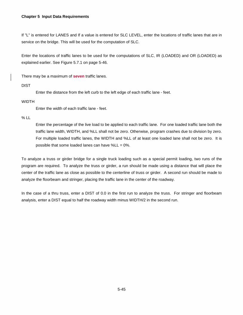
Chapter 5 Input Data Requirements
5-45
If "L" is entered for LANES and If a value is entered for SLC LEVEL, enter the locations of traffic lanes that are in
service on the bridge. This will be used for the computation of SLC.
Enter the locations of traffic lanes to be used for the computations of SLC, IR (LOADED) and OR (LOADED) as
explained earlier. See Figure 5.7.1 on page 5-46.
There may be a maximum of seven traffic lanes.
DIST
Enter the distance from the left curb to the left edge of each traffic lane - feet.
WIDTH
Enter the width of each traffic lane - feet.
% LL
Enter the percentage of the live load to be applied to each traffic lane. For one loaded traffic lane both the
traffic lane width, WIDTH, and %LL shall not be zero. Otherwise, program crashes due to division by zero.
For multiple loaded traffic lanes, the WIDTH and %LL of at least one loaded lane shall not be zero. It is
possible that some loaded lanes can have %LL = 0%.
To analyze a truss or girder bridge for a single truck loading such as a special permit loading, two runs of the
program are required. To analyze the truss or girder, a run should be made using a distance that will place the
center of the traffic lane as close as possible to the centerline of truss or girder. A second run should be made to
analyze the floorbeam and stringer, placing the traffic lane in the center of the roadway.
In the case of a thru truss, enter a DIST of 0.0 in the first run to analyze the truss. For stringer and floorbeam
analysis, enter a DIST equal to half the roadway width minus WIDTH/2 in the second run.
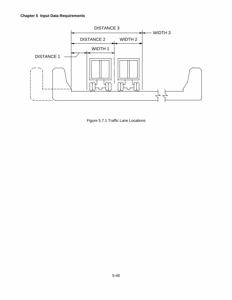
Chapter 5 Input Data Requirements
5-46
Figure 5.7.1 Traffic Lane Locations
DISTANCE 1
WIDTH 3DISTANCE 3
DISTANCE 2 WIDTH 2
WIDTH 1

Chapter 5 Input Data Requirements
5-47
STRINGER SPAN LENGTHS
Enter the stringer span lengths for the bridge types “FSS”, "GFS", and "TFS" or the floorbeam spacings for the
bridge types "GFF" and "TFF". See Figure 5.8.1 on page 5-48. Do not enter this line for all other bridge types.
A maximum of fifteen spans (or spacings) may be entered.
The span lengths (or spacings) entered here should correspond to floorbeams (entered later in Steel Beam
Properties) to be rated. For example, if the floorbeams 2 and 3 are to be rated, spans 1, 2, 3 and 4 must be entered.
CONT
Enter "C" if the stringer or the deck is to be analyzed as continuous spans over floorbeams.
Enter "S" if the stringer or the deck is to be analyzed as simple spans over floorbeams.
This code is used to determine how the reaction on the floorbeam from the stringer or the deck is to be
computed.
1, 2 ….15
Stringer span lengths or floorbeam spacings - feet.
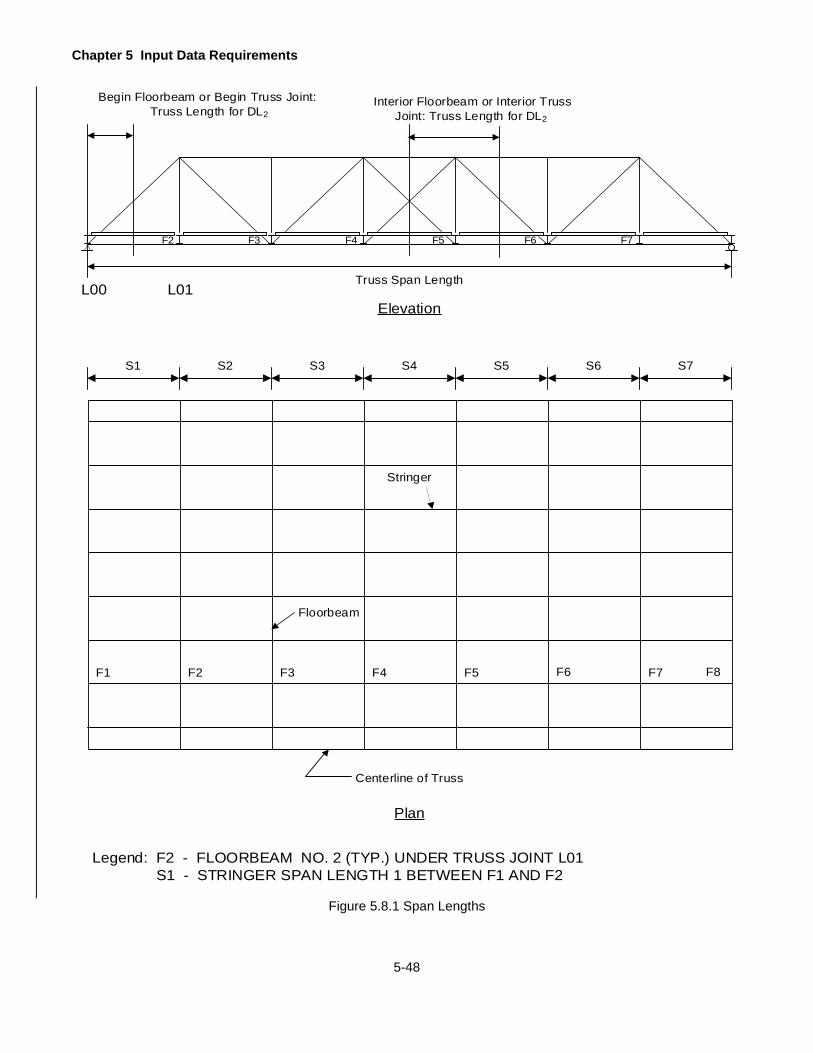
Chapter 5 Input Data Requirements
5-48
Centerline of Truss
Floorbeam
S7S6S5S4S3S2S1
Stringer
F1 F2 F3 F4 F5 F6 F7
F2 F3 F4 F5 F6 F7
Interior Floorbeam or Interior Truss Joint: Truss Length for DL2
Begin Floorbeam or Begin Truss Joint: Truss Length for DL2
Truss Span Length
Plan
Elevation
Legend: F2 - FLOORBEAM NO. 2 (TYP.) UNDER TRUSS JOINT L01 S1 - STRINGER SPAN LENGTH 1 BETWEEN F1 AND F2
L00 L01
F8
Figure 5.8.1 Span Lengths

Chapter 5 Input Data Requirements
5-49
STRINGER LOCATIONS
Enter stringer locations for the bridge types "FSS", “GFS” and "TFS" or girder locations for bridge type “GGF”. Do
not enter this line for all other bridge types. There may be a maximum of fifteen stringers/girders (stringer lines).
Refer to Figure 5.9.1 on page 5-50 for stringer/girder (stringer line) locations. If the deck is directly supported by
the main girder, the locations of the main girders should also be entered as stringer locations. The numbers in
Figure 5.9.1 Stringer Locations on page 5-50 indicate the stringer locations.
1,2 ... 15
The distance from the centerline of the left main girder, truss, or support to the centerline of each
stringer/girder - feet. This distance is negative for stringers/girders to the left of the girder, truss or support
and positive for stringers/girders to the right of the girder, truss or support.
NOTE: To accommodate negative values less than -9.99, omit the minus sign and use an alphabetic character in
the first column of this item as follows: Enter A for a value -10.00 thru -19.99, B for a value -20.00 thru -29.99, C for
a value -30.00 thru -39.99, etc. As an example, to enter the negative distance -17.55, code A755 for this input item.
The negative distance –22.25 should be coded B225.
NOTE: The distance measured from the left edge of the deck to the first stringer/girder must be equal to the distance
measured from the right edge of the deck to the last stringer/girder.

Chapter 5 Input Data Requirements
5-50
Figure 5.9.1 Stringer Locations
1 2 3 4 5 6 7
C OF GIRDER TO CURB (-)L
GIRDER SPACING (TYP.)
C OF GIRDER TO CURB (-)L1 2 3 4 5 6
C OF GIRDER TO CURB (-)L
1 2 3 4 5 6 7 8 9
STRINGER
FLOORBEAM
1 2 3 4 5
C OF TRUSS TO CURB (+)L
C T
RU
SSL

Chapter 5 Input Data Requirements
5-51
CONCRETE MEMBER PROPERTIES
This line must be entered for the Bridge Type “CPL”, "CSL", or "CTB". See Figure 5.10.1 on page 5-54. This line
must be entered for other bridge types if a "Y" is entered for CONC DECK in the Project Identification line. For
other bridge types, if a "Y" is not entered for CONC DECK in the Project Identification line, do not enter this line.
TYPE
Enter "T" if the properties entered are for a T-beam (“CTB”) bridge.
Enter "S" if the properties entered are for a Slab (“CPL” or “CSL”) bridge. Enter “O” if the properties entered are for a steel bridge.
DEPTH
The distance from the top of the slab to the bottom of the web on a T-beam bridge - inches.
The depth of the slab for bridge types “CPL” and “CSL” – inches.
Leave blank for all other bridge types.
B
The width of the web for the bridge type "CTB" - inches.
The width of the precast concrete slab for the bridge type "CPL" - inches.
Leave blank for all other bridge types.
D
For bridge type "CPL", "CSL", or "CTB", enter the distance of the tension reinforcement (AS) from the top
of the section excluding the integral wearing surface - inches.
For other bridge types, enter the distance of the center of gravity of the transverse reinforcement from the
top of the slab excluding the integral wearing surface - inches. This value is used in calculating the section
modulus at the center of gravity of reinforcement for composite section in a negative moment region of a
transverse member (composite cantilever floorbeam).
AS
For bridge types "CPL", or "CSL" or "CTB", enter the area of the tension reinforcement – in2. For concrete
slab bridges (type “CSL”), enter the area of reinforcement per foot of slab width. For precast concrete slab
bridges (type “CPL”), enter the area of tension reinforcement for width B entered above. For concrete T-
beams (type “CTB”), enter the area of tension reinforcement in the web.
For other bridge types, enter the area of the transverse reinforcement per foot of slab that is to be included
in calculating the stress/strength of a composite section in a negative moment region of a transverse
member (composite cantilever floorbeam) - in2.

Chapter 5 Input Data Requirements
5-52
D’
For bridge type "CPL", "CSL" or "CTB", enter the distance of the compression reinforcement (A'S) from the
top of the section excluding the integral wearing surface - inches. Leave blank if there is no compression
reinforcement or if it is desired not to include the compression reinforcement in the analysis.
For other bridge types, enter the distance of the center of gravity of the longitudinal reinforcement from the
top of the slab excluding the integral wearing surface - inches. This value is used in calculating the section
modulus at the center of gravity of reinforcement for composite section in a negative moment region of a
girder or stringer.
A’S
For bridge type "CPL", "CSL", or "CTB", enter the area of the compression reinforcement - in2. For concrete
slab bridges (type “CSL”), enter the area of reinforcement per foot of slab width. For precast concrete slab
bridges (type “CPL”) or concrete T-beams (type “CTB”), enter the area of compression reinforcement for
width B entered above.
For other bridge types, enter the area of longitudinal reinforcement per foot of slab that is to be included in
calculating the stress/strength of a composite section in a negative moment region of a girder or stringer -
in2.
FY REINF
Enter the yield strength of reinforcing steel - ksi. The program assumes a value of 33 ksi if this is left blank.
The program uses this value to calculate the Load Factor ratings.
ALLOWABLE Fs – IR
Enter the allowable stress in reinforcement at the Inventory stress level - ksi. The program assumes a
value corresponding to Fy as given in Section 3.6.1 Allowable Stresses if this is left blank. The program
uses this value to calculate the Inventory Rating based on the Allowable Stress Method.
ALLOWABLE Fs – OR
Enter the allowable stress in reinforcement at the Operating stress level - ksi. The program assumes a
value corresponding to Fy as given in Section 3.6.1 Allowable Stresses if this is left blank. The program
uses this value to calculate the Operating Rating based on the Allowable Stress Method.
ST DET
For bridge type "CTB" or "CPL", enter "Y" if stirrups are used for shear reinforcement. If "Y" is entered
here, also enter data on the STIRRUP DETAILS line.
Leave blank for all other bridge types.

Chapter 5 Input Data Requirements
5-53
Av
For bridge type "CTB", "CPL" or "CSL", enter the area of bent up bars that are used for shear reinforcement
– in2. Enter the area of shear reinforcement per foot width of the slab for bridge type "CSL". Only one set
of bent up bars is considered. The area of bent up bars is assumed to be effective from the centerline of
bearing to a distance equal to DEPTH/Tan(ALPHA). If more than one set of bent up bars is to be considered
for the bridge, only those bent up bars within the distance equal to DEPTH/Tan(ALPHA) should be included
in Av. Other sets of bent up bars should be accounted for by entering a modified stirrup spacing that will
provide actual shear resistance in that region.
Leave blank for all other bridge types.
SPECS
For bridge type "CPL", "CSL" or "CTB", enter a code to indicate the specifications to be used when
calculating shear ratings. Leave blank for all other bridge types.
Enter "4" or leave blank if the program should use the 1974 interim or later AASHTO Specifications for
shear ratings of a reinforced concrete member.
Enter "3" if the program should use the 1973 or earlier AASHTO Specifications for shear ratings of a
reinforced concrete member. This should only be used for the rating of an existing bridge that was designed
using the 1973 or earlier AASHTO Specifications.
ALPHA
For bridge type "CPL", "CSL", or "CTB", enter the angle of bent up bars to be used as shear reinforcement
- degrees. The angle is measured from the horizontal line parallel to the slab. The default is 45º. Leave
blank for all other bridge types.
INT WEAR SURFACE
For bridge type "CPL", "CSL", or "CTB", enter the depth of the integral wearing surface - inches. The
program assumes a value of 0.5 inches if this is left blank. For all other bridges with a composite concrete deck, enter the depth of the integral wearing surface – inches. The program assumes a default value of 0.5 inches if this is left blank for this type of bridge. For the calculation of the composite section properties, this thickness will be deducted from the slab thickness.

Chapter 5 Input Data Requirements
5-54
Figure 5.10.1 Concrete Member Properties
CONCRETE SLAB BRIDGE
A's/FT.
As/FT.
DEP
TH
D'
D
INTEGRAL WEARING SURFACE (IF ANY)
PRECAST CONCRETE SLAB BRIDGE
A's
As
DEP
TH
D'
DINTEGRAL WEARING
SURFACE (IF ANY)
CONCRETE T-BEAM BRIDGE
A's
As
DEP
THD
INTEGRAL WEARING SURFACE (IF ANY)
B
D'
B
SLABTHICKNESS
Chapter 5 Input Data Requirements
5-55
STIRRUP DETAILS
If shear ratings of a reinforced concrete T-beam or slab bridge are desired, and if "Y" was entered for ST DET on
the CONCRETE MEMBER PROPERTIES line, enter stirrup details as follows.
STIRRUP AREA
The cross-sectional area of each leg of stirrup – in2. The program assumes a two-legged vertical stirrup
and multiplies the entered values by 2 to calculate the area of shear reinforcement, Av. The program assumes a default value of 0.2 in^2 if this is left blank.
fsy
Enter the yield strength of stirrups - ksi. The program assumes a default value pf 60 ksi if this is left blank.
LOCATION
The distance of the beginning of stirrup spacing entered next from the centerline of bearing - feet. The
value of LOCATION for the first stirrup spacing is always zero.
SPACING
The stirrup spacing corresponding to the LOCATION entered before - inches. As an example for a 100'
span, if the stirrup spacings are 10 inches up to the quarter point of the span and 20 inches from the quarter
point to mid span, enter 0.00 and 10.000 for the first LOCATION and SPACING and enter 25.00 and 20.000
for the second LOCATION and SPACING respectively.
For a constant stirrup spacing, enter zero for LOCATION and the corresponding stirrup spacing for
SPACING. Leave other data blank.

Chapter 5 Input Data Requirements
5-56
TRUSS GEOMETRY
The terminology used for describing the geometry of a truss is similar to that commonly used in the engineering
drawings. A truss consists of a number of panels (sub-frames). Each panel consists of a top chord, a bottom chord,
one or two diagonals and one or two vertical members that form the right-hand side of the panel. See Figure 5.12.1
on page 5-57. Panels are numbered in a sequential order starting with 0 at the left end of a truss. A joint is
designated as L0, U1, L2, M3 etc., where the letter indicates the joint's vertical position (U for the upper joint, L for
the lower joint and M for the middle joint) and the number indicates the panel where this joint lies. A member is
designated as U1U2, L2L3, and M4U5 etc. indicating the joints it connects. The arrangement of members within a
panel is designated by a panel type. Refer to Figure 5.12.2 on page 5-58 for different panel types. The geometry
of a truss is defined by entering the width, height and type of each panel. If the truss has a vertical member at the
left end, an imaginary panel (number 0) having zero width and height equal to length of that vertical (L0U0) member
is assumed.
Figure 5.12.1 on page 5-57 shows the left half of a 10-panel truss. U0, U1, U2 etc. are upper joints and L0, L1, L2
etc. are lower joints. Panel numbers are shown as 1, 2, 3 etc. Panel types are shown as 6, 8, 11 etc. The geometry
of panels 1 and 4 are also shown in Figure 5.12.1 on page 5-57. Member L0U0 belongs to panel number 0.
Enter one line of data for each panel.
If the truss is symmetric and SYMMETRY was entered as "Y" in the BRIDGE CROSS SECTION AND LOADING
line, describe the geometry of the truss as follows. If the truss has an odd number of panels, enter the data from
the left most panel to the right end of the central panel. If the truss has an even number of panels, enter the data
from the left most panel to the central panel point. Refer to Figure 5.12.3 on page 5-60 through Figure 5.12.5 on
page 5-62.
Enter the geometry of all panels if the truss is not symmetric.
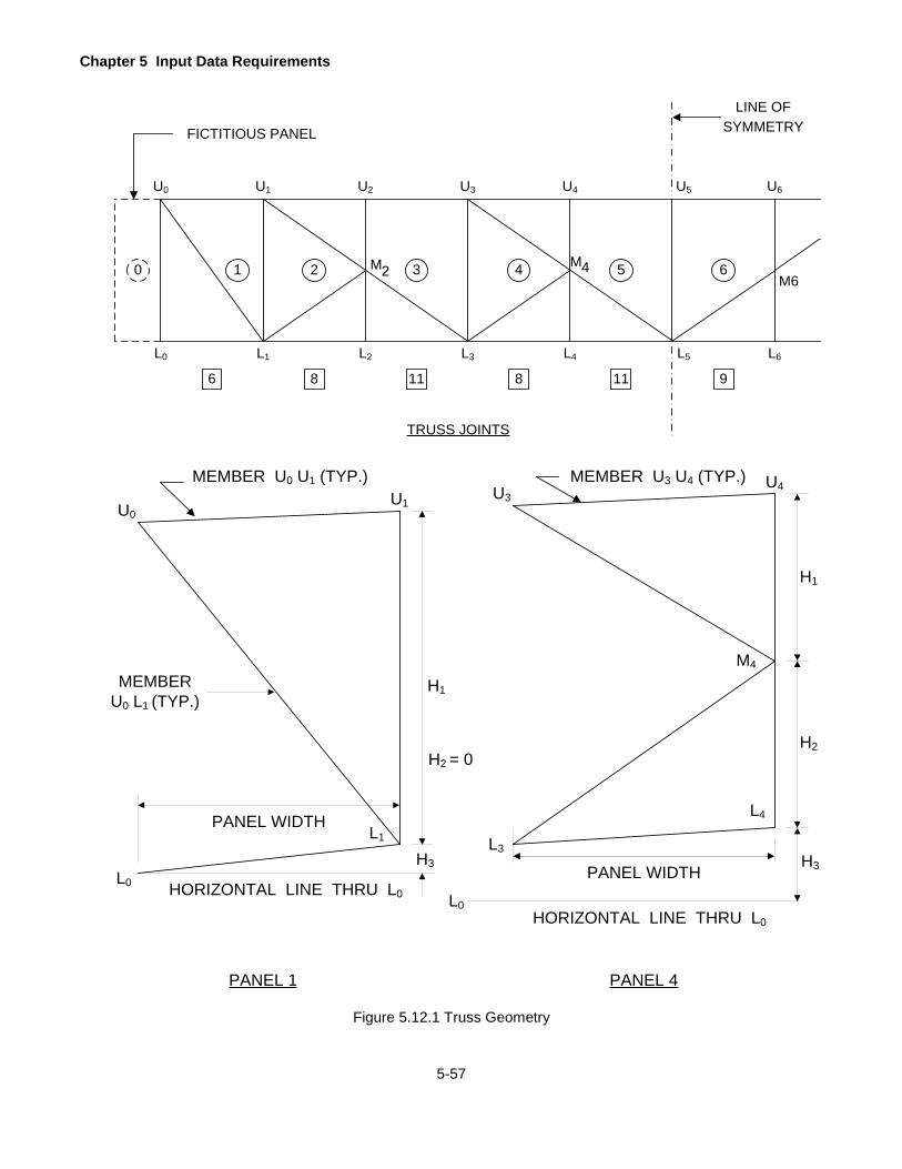
Chapter 5 Input Data Requirements
5-57
6
M66
L2
FICTITIOUS PANEL
LINE OFSYMMETRY
TRUSS JOINTS
M M2 4
L3 L4L1L0 L5 L6
543210
U0 U1 U2 U3 U4 U5 U6
8 11 8 11 9
MEMBERU0 L1 (TYP.)
PANEL WIDTH
PANEL 1
L0
L1
U0U1
H1
H3
H2 = 0
PANEL WIDTH
PANEL 4
L3
L4
U3U4
H1
H3
HORIZONTAL LINE THRU L0
H2
M4
MEMBER U3 U4 (TYP.)
L0HORIZONTAL LINE THRU L0
MEMBER U0 U1 (TYP.)
Figure 5.12.1 Truss Geometry

Chapter 5 Input Data Requirements
5-58
Figure 5.12.2 Truss Geometry - Panel Types
H1
H1 & H2 = BLANK
H1
1 2 3 4
H1 & H2 = BLANK
H1
5
H1
6
H1
7
H1
8
H2
H1
9
H2
H1
10
H2H1
11
H1
12
H1
13 14
H1
H2H1
15

Chapter 5 Input Data Requirements
5-59
PANEL NUMBER
The panel number (up to 99) for which the geometry is being described. Panels must be numbered
sequentially beginning with "0" if there is a vertical member L0U0 at the left end of the truss or beginning
with "1" if there is no vertical member L0U0. Panel 00 has only one member, L00U00.
PANEL WIDTH
The width of the panel - feet.
Enter zero if the panel number "0" is being described.
The panel width entered here must be such that the sum of all panel widths in a given span is equal to the
truss span length entered earlier.
VERTICAL POST
Y OR N
For the panel types 1, 3, 5, 6, 7, 11, 13 or 15 enter "Y" if the vertical member on the right side of the panel
is present and "N" if it is not present.
Enter "Y" if the panel "0" is being described.
If "L" is entered for LL LOCAT and the panel type is 8, 9, 10 or 14, enter "Y" if the upper vertical member
on the right side of the panel is present and enter "N" if it is not present.
If "U" is entered for LL LOCAT and the panel type is 8, 9, 10 or 14, enter "Y" if the lower vertical member
on the right side of the panel is present and enter "N" if it is not present.
Leave blank for panel types 2 and 4.
H1
The length of the vertical member on the right side of panel types 1, 3, 5, 6, 7, 11, 12, 13 or 15 or the upper
vertical member on the right side of panel types 8, 9, 10 or 14 - feet. H1 must be entered for these panel
types even if the vertical member is not present. See Figure 5.12.4 on page 5-61.
For panel number "0", enter the length of member L0U0.
Leave blank for panel types 2 and 4.
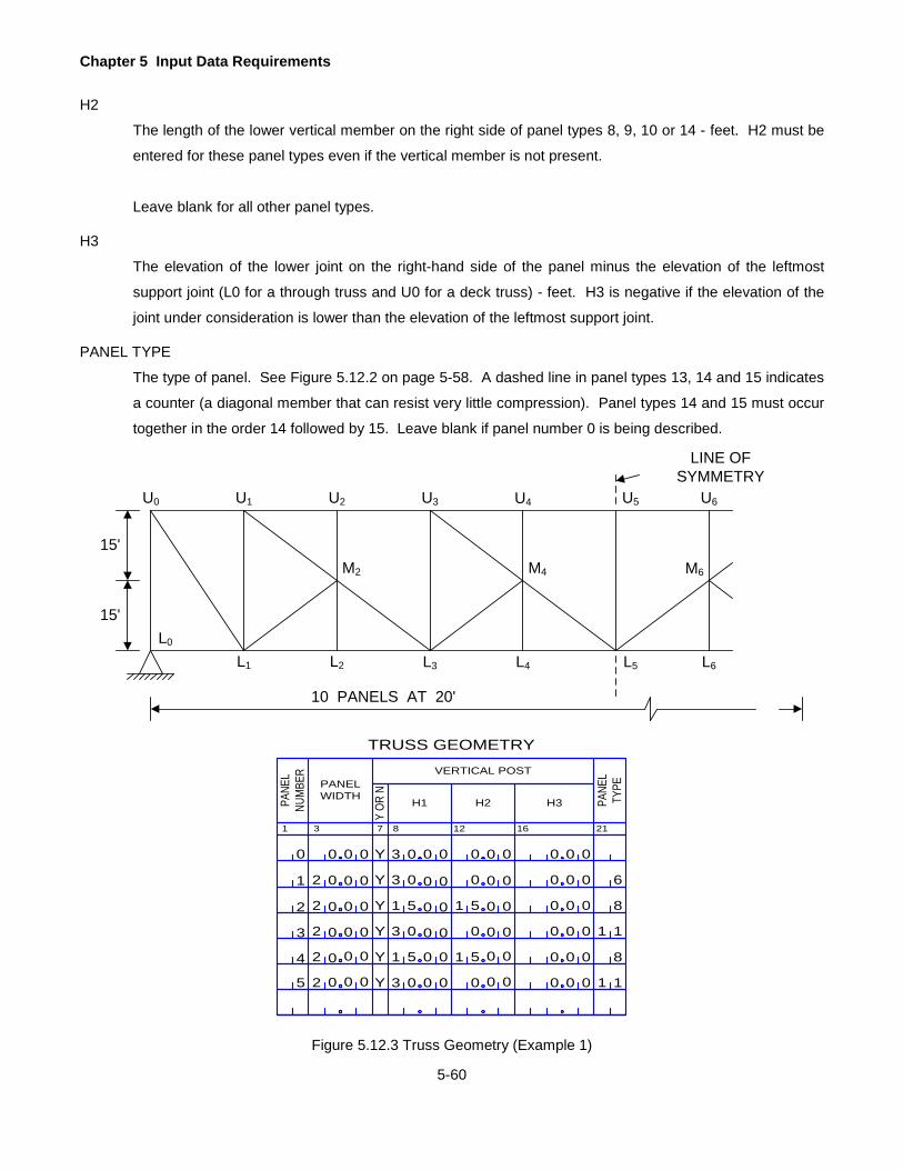
Chapter 5 Input Data Requirements
5-60
H2
The length of the lower vertical member on the right side of panel types 8, 9, 10 or 14 - feet. H2 must be
entered for these panel types even if the vertical member is not present.
Leave blank for all other panel types.
H3
The elevation of the lower joint on the right-hand side of the panel minus the elevation of the leftmost
support joint (L0 for a through truss and U0 for a deck truss) - feet. H3 is negative if the elevation of the
joint under consideration is lower than the elevation of the leftmost support joint.
PANEL TYPE
The type of panel. See Figure 5.12.2 on page 5-58. A dashed line in panel types 13, 14 and 15 indicates
a counter (a diagonal member that can resist very little compression). Panel types 14 and 15 must occur
together in the order 14 followed by 15. Leave blank if panel number 0 is being described.
Figure 5.12.3 Truss Geometry (Example 1)
U0 U1 U2 U3 U4 U5 U6
M6M4M2
L0
L1 L2 L3 L4 L5 L6
LINE OF SYMMETRY
10 PANELS AT 20'
15'
15'
1 3
PANEL WIDTHPA
NEL
NUM
BER
7 12 16
Y OR
N
TRUSS GEOMETRY
H3
218
H1 H2
VERTICAL POST
PANE
LTY
PE
0 0 0 0 Y 3 0 0 0 0 0 0 0 0 0
0 0 0
0 0 0
0 0 0
0 0 0
0 0 0
0 0
0 0
0 0
0 0
0 0
0 0
0 0
0 0
0 0
0 0
0 0
0 0
0 0
0 0
0 0
0
0
0
0
0
1
2
3
4
5
2
2
2
2
2
Y
Y
Y
Y
Y
3 0
3 0
3 0
51
51 51
51
0
0
0
6
8
1
8
1
1
1
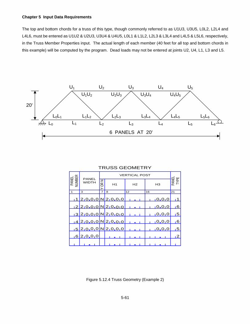
Chapter 5 Input Data Requirements
5-61
The top and bottom chords for a truss of this type, though commonly referred to as U1U3, U3U5, L0L2, L2L4 and
L4L6, must be entered as U1U2 & U2U3, U3U4 & U4U5, L0L1 & L1L2, L2L3 & L3L4 and L4L5 & L5L6, respectively,
in the Truss Member Properties input. The actual length of each member (40 feet for all top and bottom chords in
this example) will be computed by the program. Dead loads may not be entered at joints U2, U4, L1, L3 and L5.
Figure 5.12.4 Truss Geometry (Example 2)
U1 U2 U3 U4 U5
L0
L0L1
L2 L3 L4 L5 L6
6 PANELS AT 20'
20'
L1
L1L2 L2L3 L3L4 L4L5 L5L6
U4U5U3U4U2U3U1U2
1 3
PANEL WIDTHPA
NEL
NUMB
ER
7 12 16
Y OR
N
TRUSS GEOMETRY
H3
218
H1 H2
VERTICAL POSTPA
NEL
TYPE
1 0 0 0 N 2 0 0 0 0 0 0
0 0 0
0 0 0
0 0 0
0 0 0
0 0
0 0
0 0
0 0
0 0
0 0
0 0
0 0
0 0
0
0
0
0
0
2
3
4
5
6
2
2
2
2
2
N
N
N
N
2 0
2 0
02
02
6
5
6
5
2
2 1
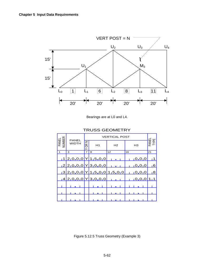
Chapter 5 Input Data Requirements
5-62
Bearings are at L0 and L4.
Figure 5.12.5 Truss Geometry (Example 3)
U1
U2 U3 U4
L0 L2 L3 L4
15'
L1
15'M3
20' 20' 20' 20'
1 6 8 11
VERT POST = N
~
1 3
PANEL WIDTHPA
NEL
NUMB
ER
7 12 16
Y OR
N
TRUSS GEOMETRY
H3
218
H1 H2
VERTICAL POST
PANE
LTY
PE1 0 0 0 Y 1 5 0 0 0 0 0
0 0 0
0 0 0
0 0 0
0 0
0 0
0 0
0 0
0 0
0 0
0
0
0
2
3
4
2
2
2
Y
Y
Y
3 0
3 0
51
6
8
1
2 1
0 051
1
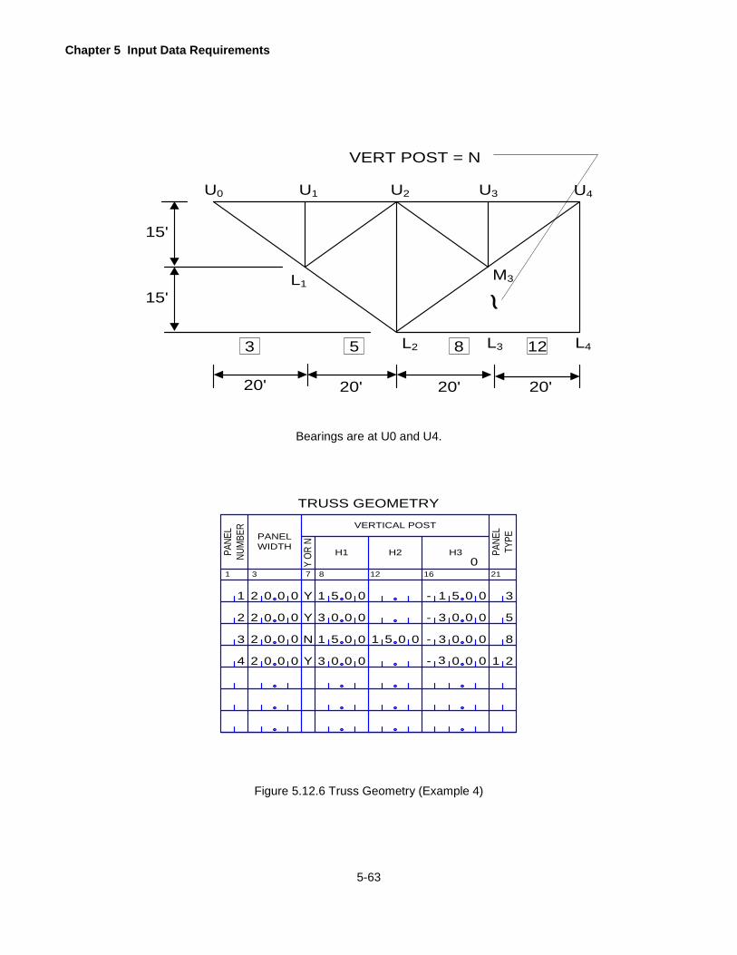
Chapter 5 Input Data Requirements
5-63
U2 U3 U4U0
L2 L3 L4
15'
U1
15'
M3
20' 20' 20' 20'
3 5 8 12
VERT POST = N
~L1
Bearings are at U0 and U4.
1 3
PANEL WIDTHPA
NEL
NUM
BER
7 12 16
Y OR
N
TRUSS GEOMETRY
H3
218
H1 H2
VERTICAL POST
PANE
LTY
PE
1 0 0 0 Y 1 5 0 0
0
0 0
0 0 0
0 0 0
0 0 0
0 0
0 0
0 0
0 0
0 0
0 0
0
0
0
2
3
4
2
2
2
Y
N
Y
3 0
3 0
51
5
8
2
2 3
0 051
1
1 5
3
-
-
-
- 3
3
Figure 5.12.6 Truss Geometry (Example 4)
Chapter 5 Input Data Requirements
5-64
TRUSS DEAD LOADS
Compute the dead load acting on each joint of the truss due to the weight of deck (slab, steel grid or timber flooring),
stringers, floorbeams, parapet, sidewalk, median, diaphragms, bracings, other hardware and attachments, sidewalk
live load and the truss itself and enter here.
If the truss is symmetric and SYMMETRY is entered as "Y" in the BRIDGE CROSS SECTION AND LOADING line,
enter the dead loads for the left half of the truss only as follows: If the truss has an odd number of panels, enter
the dead loads for joints that are on the left-hand side of the central panel about which the truss is symmetric. If
the truss has an even number of panels, enter the dead load up to and including the joint about which the truss is
symmetric.
A dead load should not be entered for a joint where both the vertical and diagonal members are not present. See
Figure 5.12.4 on page 5-61. Entering a load at such a joint will cause a bending moment in the chord member
which is not allowed. A truss member is assumed to resist axial force only.
Enter the dead loads for all joints if the truss is not symmetric.
Enter all dead loads across one line first before going to the next line. Only joints that have dead loads greater than
zero should be entered.
LOCAT
The panel point designation as defined earlier.
UL
Enter "U" if the dead load is applied at the upper panel joint.
Enter "L" if the dead load is applied at the lower panel joint.
A dead load cannot be applied at the middle panel point.
PP
The panel number where this joint belongs. The panel between FB1 and FB2 is panel 1.
This data must be entered right justified. For example, for a vertical load at L3, enter "L" under UL
and enter 3 in the rightmost column under PP.
CONC LOAD
Enter the joint dead load – kips.

Chapter 5 Input Data Requirements
5-65
TRUSS MEMBER PROPERTIES
Enter the properties of a truss member here. One line of data is required for each member.
If the truss is symmetric and SYMMETRY is entered as "Y" in the BRIDGE CROSS SECTION AND LOADING line,
enter the member properties for the left half of the truss as follows: If the truss has an odd number of panels, enter
the properties of all members up to and including the central panel about which the truss is symmetric. If the truss
has an even number of panels, enter the member properties for all panels up to the joint about which the truss is
symmetric. Remember that the vertical members that form the right-hand side of the panel belong to that panel.
Enter the properties of all members if the truss is not symmetric.
Members can be entered in any order. However, for the convenience of verifying the input data, all top chord
members may be entered first, followed by all bottom chord members, etc. Also, a member can be designated in
any way indicating its end joints. For example, a vertical member in panel number 5 can be designated as U5L5
or L5U5.
MEMBER ID
Enter the member designation indicating its end joints. Member designation is entered as follows:
UML
Indicate the joint location for each end of the member. Enter "U" if it is an upper joint, "M" if it is a
middle joint or "L" if it is a lower joint.
PP
Indicate the panel number to which this joint belongs. This data must be entered right justified. For
example, the top chord in panel 2 must be entered as Ub1Ub2 or U01U02, and not as U1bU2b
where b denotes a blank column under PP. See Figure 5.12.1 on page 5-57.
GROSS AREA COMPR
Enter the gross cross sectional area that is to be used in conjunction with Fy to calculate the allowable
compression in the member - in2. This data must be entered for all members. Enter the effective gross
area if the member has deteriorated.
NET AREA TENSION
Enter the net cross sectional area that is to be used in conjunction with FU to calculate the allowable tension
in the member – in2. This data must be entered for all members. For axial tension members with holes for
high strength bolts or rivets, the net area tension can be taken as the total cross section area minus the
area of holes. Enter the effective net area if the member has deteriorated.

Chapter 5 Input Data Requirements
5-66
MOMENT OF INERTIA
Enter the moment of inertia of the member – in4. This data must be entered for all members. This data is
used for the computation of allowable force in a compression member and thus the moment of inertia should
be considered about the weak axis of the member. Also, if the end eccentricity exists in a compression
member, the ECCENTRICITY, FLANGE WIDTH and C values entered next must correspond to the axis
about which the moment of inertia is entered. The program can check the allowable compression based
on the data entered for one axis only. If the engineer wants to investigate the allowable compression based
on these data about the other axis, it must be run as a separate problem.
FY
Enter the yield strength of the member - ksi. The allowable stresses for IR, OR, and SLC ratings are based
on the yield strength of the material. If the strength of the member is questionable, enter the appropriate
yield strength here to compensate for this.
L
Enter the actual unbraced length of the member - feet. This data is also used for the computation of
allowable force in a compression member.
The program computes the length of each member from the TRUSS GEOMETRY data entered earlier and
uses the computed length if the unbraced length of the member is not entered.
The allowable force in a compression member largely depends on the unbraced length of the member and
thus care should be exercised in entering the proper value.
For some trusses (as shown in Figure 5.12.4 on page 5-61), the unbraced length of the member may be
greater than the geometric length computed by the program. For the truss shown in Figure 5.12.4 on page
5-61, the program will compute the length of U1U2 as 20 feet. However, since a vertical is not present in
panel 2 and is coded as such in the TRUSS GEOMETRY line, the program will compute an unsupported
length of 40 feet from the actual geometry. In this case the value of L should be left blank if the joint U2 is
not adequately braced.
The following three items must be entered for a compression member where an end eccentricity exists due to end
conditions (i.e., the line joining the centers of end connections does not coincide with the neutral axis of the
member).
If the eccentricity does not exist, leave next three items blank.
ECCENTRICITY
Enter the distance of the centerline of end connections to the neutral axis about which the MOMENT OF
INERTIA is computed and entered earlier - inches.

Chapter 5 Input Data Requirements
5-67
If the eccentricity exists about both the axes of a member, enter the larger eccentricity and the
corresponding values of MOMENT OF INERTIA, FLANGE WIDTH and C. If the effect of eccentricity about
the other axis is to be checked, rerun the program entering the corresponding values of MOMENT OF
INERTIA, FLANGE WIDTH and C.
FLANGE WIDTH
The width of a compression flange - inches. Refer to Table 10.32.1A of the AASHTO Specifications.
C
The distance from the neutral axis of the member to the extreme fiber in compression - inches.
CATEGORY
If the fatigue life analysis is required for this member, enter a code that corresponds to the stress category
given in AASHTO Specifications Tables 10.3.1A and 10.3.1B. Enter the code left justified. Acceptable
codes are "A ", "B ", "BP", "C ", "CT", "D ", "E ", “EP”, “B’” and "E'", where "CT" is the stress category C in
AASHTO Specifications Table 10.3.1A for transverse stiffener welds on girder webs and flanges. Note:
“BP” is equivalent to “B’” and “EP” is equivalent to “E’”.
Leave blank if the fatigue life analysis is not required for this member.
FU
Enter the ultimate tensile strength of the member - ksi. The program uses this value to calculate the
allowable tension in a truss member as per the equations given in AASHTO Manual Tables 6.6.2.1-1 and
6.6.2.1-2.
If the ultimate tensile strength of the member is known, enter a value here. If the strength of the member
is questionable and an adjusted value was entered for FY, also enter an adjusted value for FU.
If the ultimate tensile strength of the member is not entered, the program will use the rounded values given
in the following table for the allowable tension in a truss member corresponding to the value entered for FY.
The values given in the table are derived from AASHTO Manual Tables 6.6.2.1-1 and 6.6.2.1-2 assuming
a lower value for a given FY. If your FY does not match one of the values in this table, you must enter a
value for FU.
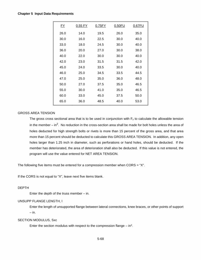
Chapter 5 Input Data Requirements
5-68
FY 0.55 FY 0.75FY 0.50FU 0.67FU
26.0 14.0 19.5 26.0 35.0
30.0 16.0 22.5 30.0 40.0
33.0 18.0 24.5 30.0 40.0
36.0 20.0 27.0 30.0 38.0
40.0 22.0 30.0 30.0 40.0
42.0 23.0 31.5 31.5 42.0
45.0 24.0 33.5 30.0 40.0
46.0 25.0 34.5 33.5 44.5
47.0 25.0 35.0 36.0 48.0
50.0 27.0 37.5 35.0 46.5
55.0 30.0 41.0 35.0 46.5
60.0 33.0 45.0 37.5 50.0
65.0 36.0 48.5 40.0 53.0
GROSS AREA TENSION
The gross cross sectional area that is to be used in conjunction with Fy to calculate the allowable tension
in the member – in2. No reduction in the cross-section area shall be made for bolt holes unless the area of
holes deducted for high strength bolts or rivets is more than 15 percent of the gross area, and that area
more than 15 percent should be deducted to calculate this GROSS AREA TENSION. In addition, any open
holes larger than 1.25 inch in diameter, such as perforations or hand holes, should be deducted. If the
member has deteriorated, the area of deterioration shall also be deducted. If this value is not entered, the
program will use the value entered for NET AREA TENSION.
The following five items must be entered for a compression member when CORS = “X”.
If the CORS is not equal to “X”, leave next five items blank.
DEPTH
Enter the depth of the truss member – in.
UNSUPP FLANGE LENGTH, l
Enter the length of unsupported flange between lateral connections, knee braces, or other points of support
– in.
SECTION MODULUS, Sxc
Enter the section modulus with respect to the compression flange – in3.

Chapter 5 Input Data Requirements
5-69
MOMENT OF INERTIA, Iyc
Enter the moment of inertia of compression flange about the vertical axis in the plane of web – in4.
TORSION INERTIA, Jxy
Enter the torsional inertia, in4, which is equal to [(bt3)c + (bt3)t + Dtw3]/3, where b and t represent the flange
width and thickness of the compression and tension flange, D is the web depth, and tw is the web thickness.
MOMENT OF INERTIA, Iy
Enter the moment of inertia (in4) for vertical members whose floorbeams require the pony truss stability
analysis. This data shall be computed assuming bending along the floorbeam direction.
Leave this field blank if the pony truss stability analysis is not needed or if the member is not a vertical
member.
Chapter 5 Input Data Requirements
5-70
ADDITIONAL TRUSS MEMBER PROPERTIES FOR LOAD FACTOR METHOD
Refer to Articles 1.7 and 1.8 in the Guide specifications for Strength Design of Truss bridges (Load Factor Design),
1985. Enter the additional properties of a truss member here for load factor rating purpose. One line of data is
required for each member.
If the truss is symmetric and SYMMETRY is entered as "Y" in the BRIDGE CROSS SECTION AND LOADING line,
enter the member properties for the left half of the truss as follows: If the truss has an odd number of panels, enter
the properties of all members up to and including the central panel about which the truss is symmetric. If the truss
has an even number of panels, enter the member properties for all panels up to the joint about which the truss is
symmetric. Remember that the vertical members that form the right-hand-side of the panel belong to that panel.
Enter the properties of all members if the truss is not symmetric.
ATM CARD IDENT
Enter the identification of the card, "ATM".
MEMBER ID
Enter the member designation indicating its end joints. Member designation is entered as follows:
Members can be entered in any order. However, for the convenience of verifying the input data, all top
chord members may be entered first, followed by all bottom chord members, etc. Also, a member can be
designated in any way indicating its end joints. For example, a vertical member in panel number 5 can be
designated as U5L5 or L5U5.
UML
Indicate the joint location for each end of the member. Enter "U" if it is an upper joint, "M" if it is a middle
joint or "L" if it is a lower joint.
PP
Indicate the panel number to which this joint belongs. This data must be entered right justified. For
example, the top chord in panel 2 must be entered as Ub1Ub2 and not as U1bU2b where b denotes a blank
column under PP.
SECTION MODULUS GROSS AREA TENSION
Enter the section modulus, based on the gross cross sectional area, which is to be used in conjunction with
Fy to calculate axial tension capacity of the member – in3. This data must be entered for all members. Use
the gross area with hand holes and perforations removed. Use effective gross area if the member has
deteriorated.

Chapter 5 Input Data Requirements
5-71
Note: The gross area shall not be used if the holes occupy more than 15% of the gross area. When they
do, the excess above 15% of the holes not greater than 1.25 in, and all of area of larger holes, should be
deducted from the gross area.
SECTION MODULUS NET AREA TENSION
Enter the section modulus, based on the net cross sectional area that is to be used in conjunction with Fu
to calculate axial tension capacity of the member – in3. This data must be entered for all members. Use
the net area with bolt holes and/or rivets holes removed. Use effective gross area if the member has
deteriorated. For axial tension members with holes for high strength bolts or rivets, the net area tension
can be taken as the total cross section area minus the area of holes.
SECTION MODULUS GROSS AREA COMPRESSION
Enter the section modulus, based on the gross cross sectional area that is to be used in conjunction with
Fy to calculate axial compression capacity of the member – in3. This data must be entered for all members.
Use the gross area with hand holes and perforations removed on the assumption that the body of the
fastener fills the hole. Use effective gross area if the member has deteriorated.
MU
Enter the maximum bending strength, reduced for lateral buckling in kips-in. Normally BAR7 computes this
item per 1985 AASHTO Strength Design of Truss Bridges. But the user has the override option by entering
a non-zero positive value.
PLAS SHAPE FAC
Enter the plastic shape factor, f, computed based on gross or gross effective properties. The plastic shape
factor is equal to Mp/My (= plastic moment/yield moment = Fy*plastic modulus/Fy* section modulus based
on gross area). This value shall be always larger than 1.0. For example, this item is 1.5 for a rectangular
section and 1.7 for a circular section.
EQUI MOM FAC
Enter the equivalent moment factor and it shall be taken as 0.85 or 1.00 as appropriate.
SHAPE
Enter the shapes of the truss members. This item is used to compute the MU of each truss member if MU
is not enterd by the user. Use 1 for box shaped members, use 2 for H-shaped members bent about their
minor axis, use 3 for H-shaped members, and members with channel flanges and a web plate, bent about
their major axis, and use 4 for others. Refer to Article 1.8 in the 1985 AASHTO Strength Design of Truss
Bridges.

Chapter 5 Input Data Requirements
5-72
BOX AREA
For box-shaped members with SHAPE = “1”, enter the box area enclosed within the centerlines of plates
of the box members in square inches.
For non box-shaped member, leave it blank.
BOX S/T
For box-shaped members with SHAPE = “1”, enter the summation of the length of a side divided by its
thickness for all sides in inches.
For non box-shaped member, leave it blank.
Iy2
For members with SHAPE = “1” or “3”, enter the moment of inertia about the axis perpendicular to the
bending axis in in4.
For others, leave it blank.
MEM H
For members with SHAPE = “3”, enter the depth of web plate plus flange thickness in inches.
For others, leave it blank.

Chapter 5 Input Data Requirements
5-73
STEEL MEMBER PROPERTIES
Enter this data to describe the section properties of the girder, encased I-beam, floorbeams, and stringers.
For the purpose of describing the steel member properties, each span is divided into a number of segments with
each segment having a constant cross section. Each segment is defined by entering the distance of the right end
of the segment from the left support of the span where this segment lies. This distance is defined as the range of
the section. Properties are entered for each range within a span. Each range must have the same dimensions for
each of the section elements (web, top flange, angles, bottom flange, cover plate) except for the web depth which
can vary (straight or parabolic haunch) within a range.
For the bridge type "GGG", enter the section properties of the girder under consideration. Only one girder can be
analyzed in a given run.
For the bridge type "EIB", enter the section properties of the encased I-beam. Only one beam can be analyzed in
a given run. The bridge must have a simple span.
For the bridge type "GFS", enter the section properties of the main girder, floorbeams and stringers. Only one main
girder, up to a maximum of five floorbeams and fifteen stringers can be analyzed in each run. Girder properties
must be entered first, followed by floorbeams and stringers.
For the bridge type "GFF", enter the section properties of the main girder and floorbeams. Only one main girder
and up to a maximum of five floorbeams can be analyzed in each run. Section properties of stringers are not
entered for this type of bridge. Enter girder properties first.
For the bridge type "TFS", enter the section properties of the floorbeams and stringers. Up to a maximum of five
floorbeams and fifteen stringers can be analyzed in each run. Enter floorbeam properties first.
For the bridge type "TFF", enter the section properties of the floorbeams only. Up to a maximum of five floorbeams
can be analyzed. Section properties of stringers are not entered for this type of bridge.
For the bridge type "GGF", enter the section properties of the girder under consideration and the floorbeams. Only
one girder can be analyzed in each run and up to a maximum of five floorbeams can be analyzed. Girder section
properties must be entered first followed by floorbeam properties. Section properties of stringers are not entered
for this type of bridge.
For the bridge type "FSS", enter the section properties of the floorbeams and stringers. Up to a maximum of five floorbeams and fifteen stringers can be analyzed in one run. Enter floorbeam properties first.
Chapter 5 Input Data Requirements
5-74
If SYMMETRY is entered as "Y" in the BRIDGE CROSS SECTION AND LOADING line, it applies only to the section
properties of the girder. If the symmetry applies, enter the section properties of the girder for one-half of the bridge.
For example, for a five-span symmetric bridge, enter the section properties of the girder up to the midpoint of span
3. For a single span bridge, enter the properties for the left half of the span. For a two-span symmetric bridge,
enter the section properties of the girder up to the interior support. If the symmetry does not apply, enter the section
properties of the girder for the entire bridge.
As stated earlier, one to five floorbeams may be analyzed. However, the floorbeam designated must correspond
to the stringer span lengths (or floorbeam spacings) entered earlier. For example, if the floorbeam 5 is to be
analyzed, stringer spans (or floorbeam spacings) 1, 2, 3, 4 and 5 must be described. Since the floorbeams are
numbered such that the left floorbeam for each span has the same number as the span number, only the floorbeam
at the left abutment and the interior floorbeams can be analyzed. Also, the program can analyze only floorbeams
for which the stringer span lengths (or the floorbeam spacings) have been defined. A floorbeam can have a variable
cross section. However, the number of different cross sections, including the cantilever portion (if any), in a
floorbeam is limited to 5.
There may be a maximum of fifteen stringers on a bridge, but each stringer must have a constant cross section. If
the stringer has a variable cross section, brace points within a span or stiffeners, analyze it by entering as bridge
type "GGG".
Section properties of the girder must be described first followed by the section properties of all floorbeams. The
section properties of stringers must be described last. For the bridge types "GFF", "GGF", and "TFF", the section
properties of stringers are not entered. For the bridge types "TFS", "TFF" and "FSS", the section properties of the
girder are not entered.
Enter one line of data for each range.
Members may be described by entering various combinations of section properties and member dimensions. The
following three cases may occur:
Case 1: A standard beam for which basic section properties are known may be described by the following data.
Refer to Figure 5.16.1 on page 5-76.
SECT TYPE (W): wide flange beam
WF BEAM M OF I (basic beam)
WF BEAM AREA (basic beam)
FLANGE THICK (basic beam)
FLANGE WIDTH (basic beam)
WF BEAM DEPTH (depth of basic beam)

Chapter 5 Input Data Requirements
5-75
WEB THICK (basic beam) TOP PLATE WIDTH (cover plate)
TOP PLATE THICK (cover plate)
BOTTOM PLATE WIDTH (cover plate)
BOTTOM PLATE THICK (cover plate)
Case 2: A built-up section made up of web plate (constant depth or straight or parabolic haunch), angles and flange
plates may be described by the following data. In a built-up section, angles are assumed to occur in pairs
at both the top and the bottom, and all angles are assumed to be of the same cross section. Refer to Figure
5.16.1 on page 5-76.
SECT TYPE (B): built-up section
ANGLE VERT LEG
ANGLE HORZ LEG
ANGLE THICK
VARIES (web plate depth variation)
WEB PLATE DEPTH (depth of web)
WEB THICK
TOP PLATE WIDTH
TOP PLATE THICK
BOTTOM PLATE WIDTH
BOTTOM PLATE THICK
Case 3: A plate girder section made up of a web plate (constant depth or straight or parabolic haunch) and flange
plates may be described by the following data. Refer to Figure 5.16.1 on page 5-76.
SECT TYPE (P): plate girder
VARIES (web plate depth variation)
WEB PLATE DEPTH (web)
WEB THICK (web)
TOP PLATE WIDTH (top flange)
TOP PLATE THICK (top flange)
BOTTOM PLATE WIDTH (bottom flange)
BOTTOM PLATE THICK (bottom flange)

Chapter 5 Input Data Requirements
5-76
SLAB THICK.HAUNCH
WF
BEAM
DEP
THWEB THICK.
WF BEAM
WIDE FLANGE BEAM (COMPOSITE)
BOTTOM PLATE
TOP PLATE WIDTH
CG TOP (-)
TOPPLATETHICK.
WEB THICK.
CG BOT (+)
BOTTOMPLATE WIDTH
BOTTOMPLATETHICK.
WEB
PLA
TE D
EPTH
PLATE GIRDER
CG
CG
TOP PLATEWIDTH
ANGLETHICK.
TOPPLATETHICK.
BOTTOMPLATETHICK.
ANGLEHORZ.LEG
WEBTHICK.
BOTTOMPLATE WIDTH
BUILT-UP SECTION
WEB
PLA
TE D
EPTH
ANGLEVERT.LEG
Figure 5.16.1 Steel Member Properties

Chapter 5 Input Data Requirements
5-77
G F OR S
Enter the following codes to describe the section properties in the following order. Entering in any other
order will result in error conditions.
1. Enter "G" if a girder or an encased I-beam is being described. A maximum of 300 lines (150 if
SYMMETRY is entered as "Y") are permitted to define the girder section properties.
2. Enter "F" if a floorbeam is being described. The maximum number of floorbeams that can be analyzed
is limited to 5. Do not enter this line for the bridge type "EIB", "FSS" or "GGG".
3. Enter "S" if a stringer is being described. These must be the last lines of data defining the steel member
properties for the bridge types "FSS", "GFS", and "TFS". Do not enter this line for the bridge types
"EIB", "GFF", "GGF", "GGG", and "TFF".
SPAN NO
If a girder is being described, enter the span number of the girder. Use the letter "A", "B", "C", "D", "E" and
"F" for span 10, 11, 12, 13, 14 and 15 respectively.
If a floorbeam is being described, enter the number of the stringer span to the right of the floorbeam (from
"1" to "G"). If SPAN NO equals "1", the floorbeam is analyzed as an exterior (end, usually at begin abutment or truss joint 00) floorbeam.
If a stringer is being described and a specific stringer is to be analyzed, enter the number of the stringer
line to be analyzed. Refer to Stringer Locations data and count sequentially from the left to the stringer to
be analyzed. If this item is left blank, the program will determine the critical stringer and analyze only that
stringer line. SPAN NO must be entered sequentially.
RANGE
The distance from the left girder, truss, or support of the span to the right end of this segment - feet.
GIRDER:
Girders are described in ascending span number, working from left to right. The RANGE cannot be greater
than the span length. The RANGE for the last segment in each span must be equal to the span length.
The first RANGE in each girder span must not be zero. The maximum number of girder RANGEs for a
given girder is one hundred.
If the girder has a parabolic or straight haunch and if the top and/or bottom plate dimensions vary within the
haunched segment, the haunched segment shall be divided into separate RANGEs with each RANGE
having constant top and bottom plate dimensions.

Chapter 5 Input Data Requirements
5-78
FLOOR BEAM: If a floorbeam is being described, start with a section at the centerline of the left girder, truss, or support
(zero RANGE). For left cantilever span, describe all sections in the cantilever portion of the floorbeam by entering a
negative value for the RANGE. The last negative value of the RANGE must be equal to the value of
OVERHANG entered in the BRIDGE CROSS SECTION AND LOADING line. For symmetric floor beam span, describe all sections of the floorbeam between the centerline of the left girder, truss, or support and the midpoint of the floorbeam span by entering positive value. The
last positive value of the RANGE must be equal to one-half the center-to-center distance between girders
or trusses. The maximum number of floorbeam RANGEs for a given floorbeam is five. When the whole floorbeam analysis is needed (i.e. UNSYM PIER = “Y” OR Patch load for floorbeam), describe all sections in the floorbeam including all cantilevers. For unsymmetrical floorbeam span, describe all sections of the floorbeam between the centerline of the left girder, truss, or support and the centerline of the right girder, truss, or support by entering positive values. The last positive value of the RANGE must be equal to the center-to-center distance between left girder (or truss or support) or right girder (or truss or support). For right cantilever span, describe all sections in the cantilever portion of the floorbeam by entering a positive value for the RANGE. The last positive value of the RANGE must be equal to the end of right cantilever span.
STRINGER: If a stringer is being described, leave blank. No variation in section properties is allowed in a stringer.
SECT TYPE
Enter one of the following codes to define the type of section.
1. Enter "W" if the section is a wide flange beam.
2. Enter "B" if the section is a built-up section made up of web plate, angles and flange plates.
3. Enter "P" if the section is a welded plate girder.
This code must be entered on the first line of data for each member type (girder, floorbeam or stringer), i.e.
whenever either "G", "F" or "S" is entered the first time for the input item G, F OR S. Thereafter, if this item
is left blank, the program will assume the section type of the previous RANGE having a non-blank SECT
TYPE. For each RANGE a different SECT TYPE may be entered.

Chapter 5 Input Data Requirements
5-79
WF BEAM M OF I OR ANGLE VERT LEG
If "W" is entered for SECT TYPE, enter the moment of inertia of the wide flange beam – in4.
If "B" is entered for SECT TYPE, enter the length of the vertical leg of the angle - inches.
If "P" is entered for SECT TYPE, leave blank.
WF BEAM AREA OR ANGLE HORZ LEG
If "W" is entered for SECT TYPE, enter the area of the wide flange beam - in4.
If "B" is entered for SECT TYPE, enter the length of the horizontal leg of the angle - inches.
If "P" is entered for SECT TYPE, leave blank.
FLANGE OR ANGLE THICK
If "W" is entered for SECT TYPE, enter the flange thickness of the wide flange beam - inches.
If "B" is entered for SECT TYPE, enter the thickness of the angle - inches.
If "P" is entered for SECT TYPE, leave blank.
FLANGE WIDTH
If "W" is entered for SECT TYPE, enter the flange width of the wide flange beam - inches.
If "B" or "P" is entered for SECT TYPE, leave blank.
VARIES
For a non-prismatic segment where the left depth of the previous range and right depth of the current range are different, enter "P" if the variation in depth within this segment is parabolic and "S" if it is straight.
Leave blank for a constant depth. The program uses the equation y = cx2 for the parabolic haunch. parabolically varied @ X=60 vs not varied
RANGE X DEPTH X DEPTH 0.00 44.75 0.00 44.75 12.00 44.75 12.00 44.75 24.00 44.75 24.00 44.75 30 30.00L 44.75 30.00L 44.75 30.00R 44.75 30.00R 54.75 36.00 45.15 36.00 54.75 48.00 48.35 48.00 54.75

Chapter 5 Input Data Requirements
5-80
60 60.00L 54.75 60.00L 54.75 60.00R 64.75 60.00R 64.75
WF BEAM OR WEB PLATE DEPTH
Enter the depth of the wide flange beam or the web plate at the right end of the segment (at a given RANGE)
being described - inches. If the section being described is in a parabolic or straight haunch and the RANGE
entered is not the end of the parabolic or straight haunch, leave this blank. If the RANGE entered is the
end of the haunch, enter the depth of web at the end of the haunch. If in a built-up section, there is a gap
between the web plate and the flanges, enter the actual distance between the bottom of the top flange and
the top of the bottom flange.
WEB THICK
The thickness of the web - inches. This must be entered for all sections. For box-shaped steel cross girders/floorbeams, enter the web thickness of only one web.
TOP PLATE
Enter the top cover plate dimensions, if one exists, for case 1.
Enter the top plate dimensions for case 2 or 3.
WIDTH
The width of the top plate or cover plate - inches.
THICK
The thickness of the top plate or cover plate - inches.
BOTTOM PLATE
Enter the bottom cover plate dimensions, if one exists, for case 1.
Enter the bottom plate dimensions for case 2 or 3.
WIDTH
The width of the bottom plate or cover plate - inches.
THICK
The thickness of the bottom plate or cover plate - inches.
COMPOSITE
For the bridge type "EIB" the program always uses the composite section properties to calculate the
stresses due to DL2 and LL+I. For this bridge type, this input value is used to differentiate between shored
and unshored construction. If shored construction, enter "Y" and the program uses the composite section
properties, (n=3n), to calculate the stresses due to DL1. If unshored construction, enter "N" and the
program uses the non-composite section properties to calculate the stresses due to DL1. This value must
be entered as "Y" or "N" for the entire length of the encased beam.

Chapter 5 Input Data Requirements
5-81
For all other bridge types, enter "Y" if the section is composite with the slab, "N" or leave it blank if it is
non-composite. The program assumes unshored construction and always uses the non-composite section
properties to calculate the stresses due to DL1.
FY
The yield strength of the material for the segment being described - ksi.
For a homogeneous section, enter the yield strength of the entire section.
For a hybrid section, enter the yield strength of the web.
HYBRID FY TOP
For a hybrid section, enter the yield strength of the top plate or cover plate - ksi.
For a homogeneous section, leave this blank.
HYBRID FY BOT
For a hybrid section, enter the yield strength of the bottom plate or cover plate - ksi.
For a homogeneous section, leave this blank.
UNSYMMETRICAL CG TOP
For a section unsymmetrical about the vertical (Y-Y) axis, enter the distance of the center of gravity of the
top plate or cover plate from the vertical centerline of the web - inches. The distance is positive to the right
and negative to the left of the web centerline.
UNSYMMETRICAL CG BOT
For a section unsymmetrical about the vertical (Y-Y) axis, enter the distance of the center of gravity of the
bottom plate or cover plate from the vertical centerline of the web - inches. The distance is positive to the
right and negative to the left of the web centerline.
NOTE: Deteriorated wide flange sections with deterioration in the flange can be described either with negative
cover plate thickness or by entering as a plate girder with unsymmetrical CG depending on the location and type of
deterioration. If a negative cover plate thickness is entered for a wide flange section and the cover plate width is
not entered, the program will assume that the section loss is over the entire width of the flange. Currently, the
program does not have any provision to enter deterioration in the web. However, if the user enters a reduced WEB
THICK to account for deterioration in the web, then the user must also account for this loss in the input of WF BEAM
M OF I and WF BEAM AREA.
Chapter 5 Input Data Requirements
5-82
SECTION SHAPE Enter I or leave it blank when the cross girder is I-shape. Enter B when the cross girder is box-shape. This will allow the simulation of non-composite, box-shaped steel cross girder (i.e. floorbeams at supports) using BAR7 to perform a rating for a non-compact section using I-shape steel girder.
LATERAL BRACE POINTS AND STIFFENER SPACINGS
These lines are required to describe the lateral brace points and stiffener spacings for a girder or floorbeam (exclude EIB). These data are required for the Load Factor rating of a member subjected to flexure and shear.
The type of data (brace points or stiffener spacings) being described is indicated by a two-character code at the
beginning of each line. Also, the data is entered for each span in succession beginning with span number one.
Each span is described by the number of spaces of a given spacing followed by the number of spaces of another
spacing and so on until the entire span is described.
Since each line has a two-character code and a span number, the order of input is not important. However, for
simplicity of coding and understanding of the input, the following sequence is suggested. Start with a girder and
describe all brace points first for all spans followed by stiffener spacings for all spans. Then describe the brace
points for all floorbeams beginning with the first floorbeam for which the section properties are entered. Follow
these by stiffener spacings for all floorbeams in the same order. The top and bottom flanges of a floorbeam shall be braced at supports and the end of the overhang.
The program does not have a provision for entering this data for a stringer of the bridge type "FSS", "GFS", or
"TFS". The program will assume that the top flange of a stringer is continuously braced. The program will also
assume that the bottom flange of a stringer is braced at the ends of each span. The program also assumes that a
stringer is unstiffened. If a stringer has brace points and stiffeners different than what the program will assume,
then the stringer in question could be analyzed by entering as bridge type "GGG".
The following is a description of each data item on this line. Figure 5.17.1 on page 5-85 shows the coding of these
items for two girders.
BRACING OR STIFF CODE
This is a two-character code which denotes the member and the type of data (brace point or stiffener
spacing) being described on this line. Enter one of the following codes.
"BG" for describing the brace points of a girder
"SG" for describing the stiffener spacings in a girder
"BF" for describing the brace points of a floorbeam
"SF" for describing the stiffener spacings in a floorbeam
Chapter 5 Input Data Requirements
5-83
SPAN NO
If a girder is being described, enter the span number of the girder. Use the letter "A", "B", "C", "D", "E" and
"F" for span 10, 11, 12, 13, 14 and 15 respectively.
If a floorbeam is being described, enter the number of the stringer span to the right of the floorbeam (from
"1" to "F"). If SPAN NO equals "1", the floorbeam is analyzed as an exterior (end, usually at abutment or truss joint 00) floorbeam. SPAN NO must be entered sequentially.
BRACE POINT OR STIFFENER CODE
Enter one of the following codes if "BG" or "BF" is entered for the BRACING OR STIFF CODE.
Enter "T" if the brace points are described for the top flange.
Enter "B" if the brace points are described for the bottom flange.
Enter "C" if the top flange is continuously braced for this number of spaces. The bottom flange
cannot be continuously braced.
Enter one of the following codes if "SG" or "SF" is entered for the BRACING OR STIFF CODE.
Enter "T" if the web is transversely stiffened for this number of spaces.
Enter "L" if the web is transversely and longitudinally stiffened for this number of spaces.
Enter "N" if the web is unstiffened for this number of spaces.
NO. OF SPACES
Enter the number of spaces having a constant spacing described next. If this data is being described for
the cantilever portion of a cantilevered floorbeam, enter a negative value.
Note: Up to 18 different brace point spacings or stiffener spacings can be entered per floorbeam.
SPACING
Enter the constant spacing - feet.
Any combination of NO. OF SPACES and SPACING can be used to define brace points and stiffener
spacings. However, the sum of products of NO. OF SPACES and SPACING for a given span number must
be within a foot of the span length. For a symmetrical member, the sum of products of NO. OF SPACES
and SPACING must be greater than or equal to the distance to the point of symmetry. The program will
assume an end of a brace point and stiffener spacing at the right end of each span.

Chapter 5 Input Data Requirements
5-84
For floorbeams with patch loads or the unsymmetrical pier configuration: 1. The sum of products of NO. OF SPACES and SPACING for left cantilever span must be within
a foot of the floorbeam main span length plus right cantilever span length. 2. The sum of products of NO. OF SPACES and SPACING for floorbeam main span and right
cantilever must be within a foot of the floorbeam main span length + right cantilever span length.
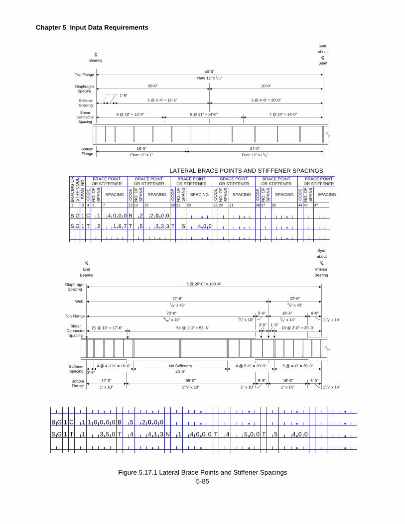
Chapter 5 Input Data Requirements
5-85
B G
GS
C
T T N
B1
1
1
1
0 5
4 1
0 0 0
053 4 1 3
2 00 0 0
4 0 0
1
0 T 4 5 0 0 T 5 4 00
Figure 5.17.1 Lateral Brace Points and Stiffener Spacings
Top Flange
DiaphragmSpacing
StiffenerSpacing
ShearConnectorSpacing
40'-0"
Plate 12" x 9/16"
20'-0" 20'-0"
BearingCL
SpanCL
aboutSym.
5 @ 3'-4" = 16'-8" 5 @ 4'-0" = 20'-0"
7 @ 24" = 14'-0"8 @ 21" = 14'-0"8 @ 18" = 12'-0"
1'-8"
16'-0"
Plate 12" x 1"
24'-0"
Plate 12" x 13/4"BottomFlange
1 3
LATERAL BRACE POINTS AND STIFFENER SPACINGS
4
BRACE POINTOR STIFFENER
75
CO
DE
SPACING
BR
AC
ING
OR
STI
FF C
OD
ES
PA
N N
O
NO
. OF
SP
AN
S
12 1513
CO
DE
NO
. OF
SP
AN
S
20 2321
CO
DE
NO
. OF
SP
AN
S
28 3129
CO
DE
NO
. OF
SP
AN
S
36 3937
CO
DE
NO
. OF
SP
AN
S
44 4745
CO
DE
NO
. OF
SP
AN
S
SPACING SPACING SPACING SPACING SPACING
BRACE POINTOR STIFFENER
BRACE POINTOR STIFFENER
BRACE POINTOR STIFFENER
BRACE POINTOR STIFFENER
BRACE POINTOR STIFFENER
B G
GS
C
T T T
B1
1
1
2
4 2
5 5
0 0 0
761 3 3 3
2 00 0 0
4 0 0
Top Flange
DiaphragmSpacing
ShearConnectorSpacing
77'-6"3/8" x 42"
Bearing
CL
Bearing
CL
aboutSym.
54 @ 1'-1" = 58'-6"21 @ 10" = 17'-6"
17'-0"
1" x 10" 11/2" x 10"BottomFlange
End Interior
5 @ 20'-0" = 100'-0"
Web22'-6"
3/8" x 42"
72'-0"9/16" x 10"
5'-6" 6'-0"16'-6"3/4" x 10" 3/4" x 14" 11/4" x 14"
55'-0" 6'-0"
1" x 10" 1" x 14" 11/2" x 14"
3'-0"10 @ 2'-0" = 20'-0"
1'-0"
StiffenerSpacing
4 @ 4'-1½" = 16'-6" No Stiffeners
3'-6" 40'-0"4 @ 5'-0" = 20'-0" 5 @ 4'-0" = 20'-0"
5'-6" 16'-6"

Chapter 5 Input Data Requirements
5-86
FATIGUE DATA
If "Y" is entered for FATIGUE in the PROJECT IDENTIFICATION line, this line of data must be entered. Enter the
following as required.
YEAR BUILT
Enter the calendar year in which the bridge was built. If it is unknown, enter an estimated year. The
program uses this value to calculate the average daily truck traffic (ADTT) for the year the bridge was built.
This must be entered.
PREVIOUS COUNT - YEAR OR GF
If an ADTT for a previous count is known, enter the year in which this count was taken.
If the rate of growth in ADTT for the past is known, enter the rate expressed as 100 times the percent
growth. For example, if the past growth in ADTT was 2.5%, enter 0250. The program will divide the entered
value by 100 and use it as a growth factor, in percent.
If the ADTT was constant (no growth) in the past, enter zero or leave blank.
PREVIOUS COUNT - ADTT
If a year is entered for PREVIOUS COUNT - YEAR OR GF, enter the average daily truck traffic count for
the previous count.
If a growth factor is entered for PREVIOUS COUNT - YEAR OR GF, leave this blank.
The program uses this data to determine whether the past growth factor is entered or it is to be calculated.
For the purpose of fatigue analysis, ADTT is a one directional average daily truck traffic on the bridge in
number of trucks per day.
RECENT COUNT - YEAR
Enter the year in which the most recent ADTT count was taken. This must be entered.
RECENT COUNT - ADTT
Enter the average daily truck traffic count for the year when the most recent ADTT count was taken. This
must be entered. If the PREVIOUS COUNT - GF is entered as zero, the program will use this ADTT from
the year built to the year of recent count.
FUTURE COUNT - YEAR OR GF
If an ADTT for the future can be predicted, enter the year for which the ADTT is predicted. Preferably this
should not be later than 10 years into the future.

Chapter 5 Input Data Requirements
5-87
If the rate of growth in ADTT for the future can be predicted, enter the rate expressed as 100 times the
percent growth. For example, if the future growth in ADTT is predicted to be 5%, enter 0500. Enter zero
or leave blank if no growth factor is to be considered for the future.
FUTURE COUNT - ADTT
If an ADTT value for the future can be predicted, enter the ADTT for FUTURE COUNT - YEAR.
If FUTURE COUNT - YEAR OR GF is left blank, enter the ADTT that will remain constant in the future.
R OR N
Specify whether the structure in question has redundant load paths or non-redundant load paths.
Enter "R" if the structure has redundant load paths.
Enter "N" if the structure has non-redundant load paths.
This data is used in determining the allowable fatigue stress range of a detail.
ONE LANE DISTR FACTOR
The live load distribution factor is for loading only one lane on the bridge. Enter this as a fraction of axle
load, i.e. one-half of the wheel load distribution factor.
For the bridge type "GGG", enter one-half of the wheel load distribution factor for one lane (e.g. S/14 for
steel girder bridge with concrete deck).
For the main girder of the bridge types "GFS" and "GFF" and for the truss of the bridge types "TFS" and
"TFF", use the simple beam reaction at the girder or truss due to a single HS20 truck in a lane positioned
closest to the girder or truss.
This data must be entered. This is used in calculating the design fatigue stress range due to an HS20 truck
in one lane.
NO OF GVWD
If the loadometer surveys of the gross vehicle weight distribution on the bridge are available and if the
gamma factor in the effective stress range equation is to be calculated using a rigorous method described
in DM4, enter the number of gross vehicle weight ranges that were used in the loadometer surveys.
If the loadometer surveys are not available or if the rigorous method for calculating the effective stress
range is not to be used, leave this blank. If this is left blank, the program will use a gamma factor of 0.7
times the Pennsylvania Traffic Factor (PTF) to calculate the effective stress range.
Chapter 5 Input Data Requirements
5-88
If a number greater than zero is entered here, also enter GROSS VEHICLE WEIGHT DISTRIBUTION data
as described later.
GIRDER FATIGUE DETAIL
If "Y" is entered for FATIGUE in the PROJECT IDENTIFICATION line and if the bridge type is "GFS", "GFF", "GGG"
or "GGF", fatigue prone details in the girder must be entered here. The program performs the fatigue life analysis
of each detail described here and calculates the minimum remaining life of the bridge. The location of a detail is
described by giving a horizontal distance of the section from the left centerline of bearing of the span where this
section is located and a vertical distance measured from the bottom most fiber of the section where this detail is
located. Only the details for which the fatigue life analysis is required may be entered here. The last section entered
here must be the right centerline of bearing of the last span regardless whether a fatigue prone detail exists there
or not. If SYMMETRY is entered as "Y" in the BRIDGE CROSS SECTION AND LOADING line, then the last section
entered here must be the center of the bridge. A maximum of 80 sections can be entered with a maximum of 4
details at each section. Enter the following data.
SPAN NO
The span number where this section is located. Use the letter "A", "B", "C", "D", "E" and "F" for span 10,
11, 12, 13, 14 and 15 respectively.
DIST FROM CL BEARING
The distance of the section from the left centerline of bearing of the span where this section is located -
feet. The last distance entered here must be equal to the length of the last span if the bridge is
unsymmetrical (i.e. if "Y" is not entered for SYMMETRY in the BRIDGE CROSS SECTION AND LOADING
line) or must be equal to the distance of the symmetry point if the bridge is symmetric (i.e. if "Y" is entered
for SYMMETRY in the BRIDGE CROSS SECTION line).
DIST FROM BOTTOM
For each detail at a given section, enter the vertical distance from the bottom most fiber at that section -
inches. If the section where this detail is located falls at a junction of two different cross sectional areas
(such as cover plate transitions or cut-offs), measure the vertical distance from the bottom fiber of the
smaller cross sectional area. The value entered should always be positive. The fatigue stress range is
calculated at this level for the fatigue life analysis.
CATEGORY
Enter a code that corresponds to the stress category given in AASHTO Specifications Tables 10.3.1A and
10.3.1B. Enter the code left justified. Acceptable codes are "A ", "B ", "BP", "C ", "CT", "D ", "E ", “EP”, “B’”
and "E'", where "CT" is the stress category C in AASHTO Specifications Table 10.3.1A for transverse
stiffener welds on girder webs and flanges. Note: “BP” is equivalent to “B’” and “EP” is equivalent to “E’”.
Do not leave this blank.

Chapter 5 Input Data Requirements
5-89
GROSS VEHICLE WEIGHT DISTRIBUTION
If the loadometer surveys of the gross vehicle weight distribution on the bridge are available and if a number greater
than zero is entered for NO OF GVWD in the FATIGUE DATA line, enter the following.
GROSS VEHICLE WEIGHT – MIN
The minimum gross vehicle weight in this range used for surveys - kips. If this is the last range that includes
all weights over a certain value, enter that "over value" here.
GROSS VEHICLE WEIGHT - MAX
The maximum gross vehicle weight in this range used for surveys - kips. If this is the last range which
includes all vehicle weights over a certain value, enter that "over value" here also.
NO OF SINGLE UNIT TRUCKS - 2 AXLE, 3 AXLE, 4 AXLE
The number of single unit trucks with 2 axles, 3 axles and 4 axles respectively in this range of gross vehicle
weights.
NO OF TRACTOR TRAILER COMB - 3 AXLE, 4 AXLE, 5 OR > AXLE
The number of tractor-trailer combinations with 3 axles, 4 axles, and 5 or more axles respectively in this
range of gross vehicle weights.
Chapter 5 Input Data Requirements
5-90
SPECIAL LIVE LOADING
This form is used to describe the parameters of special live loadings that the user can use in place of the standard
live loadings that are stored in the program. A special live loading consists of two parts: a Lane Loading and a
Truck Load. The program analyzes the bridge for both loads separately and stores the governing effects. Enter
this data if a number is entered for LIVE LOAD in the PROJECT IDENTIFICATION line. The number of special live
loadings described here should correspond to the number entered for LIVE LOAD earlier. A separate input form
must be used for each special live loading. A maximum of eight special live loadings can be described.
A bridge can be analyzed for special live loadings in two ways. The first method is to include the description of the
special live loadings in the same input data file with other data lines described so far. The second method is to
create two input data files, one for bridge data described so far and another for the special live loadings data. The
second method allows a set of special live loadings to be run for the same bridge data. This method also allows
the users in other states to create a file of customized live loadings and analyze different bridges using this file.
Refer to Example Problem 6 for an analysis of a bridge using two data files.
5.21.1 Lane Loading
SP LL NO
Enter the identification number for the special live loading, from 1 to 8.
NUMBER OF AXLES
Enter the number of axles on the Truck Load of the special live loading. There may be a minimum
of 2 axles and a maximum of 80 axles on a Truck Load.
3% INCR
Enter Y if all entered axle loads are to be increased by 3%. This option allows checking permit
loads for a 3% over weight. If a Y is entered here, the Rating Factors calculated by the program
are based on the entered axle loads increased by 3%. If a Y is entered here, the ratings in tons
are based on the entered axle loads.
Leave blank if the entered axle loads are not to be increased.
UNIFORM LANE LOAD
The uniform lane load to be used in combination with the concentrated loads (described next) to
produce the maximum effect due to special lane loading - kip/ft. Enter this load per linear foot of
loaded lane.
If a value is entered, the effect of this lane loading will be compared with the effect of the truck load
(described later) and the governing effect will be used as the special live loading effect.
Chapter 5 Input Data Requirements
5-91
CONC LOAD MOMENT
The concentrated load to be used in combination with the uniform lane load to produce the
maximum moment (or truss chord member forces) at an analysis point - kips.
For the determination of maximum negative moment (or maximum top chord tension or bottom
chord compression) in a continuous span structure, the program will use two concentrated loads of
the entered value to produce the maximum effect.
CONC LOAD SHEAR
The concentrated load to be used in combination with the uniform lane load to produce the
maximum shear (or diagonal and vertical member forces) at an analysis point - kips.
GAGE DISTANCE
The lateral distance between the wheels of this special live load - feet. If a value is not entered
here, the program will use the default value of 6 feet or the value entered in the Project Identification
line.
PASSING DISTANCE
The lateral distance between adjacent wheels of passing vehicles or twice the distance from the
face of the curb to the nearest wheel (curb distance) - feet. If a value is not entered here, the
program will use the default value of 4 feet or the value entered in the Project Identification line.
VARY LAST
If the distance between the last two axles of the TRUCK LOAD of this Special Live Loading is to
be varied similar to the HS20 truck described in the AASHTO Specifications, enter "Y". Otherwise,
leave this blank.
If a "Y" is entered here and if a value is entered for the MAX AXLE DIST described next, the program
will calculate the maximum effect due to the truck load described next by varying the distance
between the last two axles from the value of DIST entered for the last axle under TRUCK LOAD
and the MAX AXLE DIST entered next.
MAX AXLE DIST
If a "Y" is entered for VARY LAST described above, enter the maximum distance between the last
two axles of the TRUCK LOAD - ft. Otherwise, leave blank.
When ‘P’ (APRAS only) is entered for OUTPUT in the PROJECT IDENTIFICATION line, an abbreviated
Lane Loading input should be entered as follows:
NUMBER OF AXLES
The number of axles on the Truck Load of the special live loading. There may be a maximum of 80
axles on a Truck Load.

Chapter 5 Input Data Requirements
5-92
This must be entered as two integer digits in columns one and two of this input record.
3% INCR
Enter Y if all entered axle loads are to be increased by 3%. This option allows checking permit
loads for a 3% over weight. If a Y is entered here, the Rating Factors calculated by the program
are based on the entered axle loads increased by 3%. If a Y is entered here, the ratings in tons
are based on the entered axle loads.
Leave blank if the entered axle loads are not to be increased.
This must be entered as a single character in column three of this input record.
GAGE DISTANCE
The lateral distance between the wheels of this special live load - feet. If a value is not entered
here, the program will use the default value of 6 feet or the value entered in the Project Identification
line.
This must be entered as a three-digit real number with an implied decimal point between the second
and third digits in columns four through six of this input record.
PASSING DISTANCE
The lateral distance between adjacent wheels of passing vehicles or twice the distance from the
face of the curb to the nearest wheel (curb distance) - feet. If a value is not entered here, the
program will use the default value of 4 feet or the value entered in the Project Identification line.
This must be entered as a three-digit real number with an implied decimal point between the second
and third digits in columns seven through nine of this input record.
5.21.2 Truck Load
AXLE LOAD
Enter the total load on the axle - kips. The number of axle loads entered must correspond to
NUMBER OF AXLES entered earlier.
DIST
Enter the distance from the axle under consideration to the next axle - feet. For example, the
distance 4 is the distance between axle 4 and axle 5. The total number of distances entered must
be one less than the total number of axle loads.
The actual axle spacing, for special loadings, may exceed the BAR7 maximum input value of 99.9
feet in a superload. For this case, insert a dummy axle with a negligible weight (minimum = 0.01
kips) to divide the axle spacing into two axle spacings, each less than or equal to 99.9 feet. See
Figure 5.21.1 below.

Chapter 5 Input Data Requirements
5-93
x > 99.9'
x1 < 99.9' x2 < 99.9'
min = 0.01 kips
DummyAxle
ActualAxle
ActualAxle
Figure 5.21.1 Axle Spacings Exceeding 99.9 Feet
Chapter 5 Input Data Requirements
5-94
GUSSET PLATE PROPERTIES
This command is used to define the geometry of the gusset plate. Only one gusset plate can be defined at each
upper or lower joint. This command can be repeated to define up to 122 joints, 61 upper and 61 lower.
If "Y" is entered for GUSSET in the BRIDGE CROSS SECTION AND LOADING line, enter these data only for the
bridge types of "TFF", "TFS" and "TTT"
If "Y" is entered for SYMMETRY in the BRIDGE CROSS SECTION AND LOADING line, you must enter only the
gusset plate properties for the panels left of the point of symmetry.
GUS CARD IDENT
Enter the identification of this card, "GUS"
GUSSET PLATE LOC1
Enter the location of the gusset plate by the joint, "U" or "L".
Note: The program can't handle the gusset plate at the middle joint, "M".
GUSSET PLATE LOC2
Enter the location of the gusset plate by the joint, 00, 01, 02, ...
Fy
Enter the minimum yield strength of the material for the gusset plate being described - ksi.
Fu
Enter the minimum ultimate strength of the material for the gusset plate being described - ksi.
Note: 1.4*Fy is used as a default value if Fu is not input.
THICK, t
Enter the thickness of the gusset plate at one side of joint which has the double-sided symmetrical gusset
plate - in. If there are different thicknesses of gusset plate per side of the double-sided gusset plate joint,
then input the average thickness of these two plates. If there are two gusset plates per side of the double-
sided gusset plate joint, then input the total thickness of these two plates.
At gusset plate locations where the members are connected by only one gusset plate and not two gusset
plates BAR 7 cannot be used to obtain accurate Operating Ratings of the Gusset Plates. BAR7 assumes
two gusset plates are present at each joint and thus divides the forces by 2.
Lower Limit: 0.25 in and Upper Limit: 4 in.

Chapter 5 Input Data Requirements
5-95
LENGTH, Ha
Enter the length of the gusset plate along a horizontal cut at or near the edge of the chord (Figure 5.22.1
on page 5-97 to Figure 5.22.4 on page 5-100, Section A-A) - in. Input the length of the larger plate if two
gusset plates are used per side.
Lower Limit: 12 in and Upper Limit: 200 in.
LENGTH, Hb
Enter the length of the gusset plate along a vertical cut on the Section B-B side of the vertical member
(Figure 5.22.1 on page 5-97 to Figure 5.22.4 on page 5-100, Section B-B) - in. Input the length of the larger
plate if two gusset plates are used per side.
Lower Limit: 0 in and Upper Limit: 200 in.
LENGTH, Hc
Enter the length of the gusset plate along a vertical cut on the Section C-C side of the vertical member
(Figure 5.22.1 on page 5-97 to Figure 5.22.4 on page 5-100, Section C-C) - in. Input the length of the larger
plate if two gusset plates are used per side.
Lower Limit: 0 in and Upper Limit: 200 in.
ECCENTRICITY, Ea
Enter the vertical distance from the line of action in the chord to the edge of the chord adjacent to the
diagonal/vertical members (Figure 5.22.1 on page 5-97 to Figure 5.22.4 on page 5-100) - in. This distance,
typically taken as half of the member width, defines where Section A-A is taken. Used to calculate the
bending moment on the horizontal cut at Section A-A due to the vertical component of the diagonal.
Lower Limit: 0 in and Upper Limit: 50 in.
ECCENTRICITY, Eb
Enter the distance from the line of action in the vertical member to the edge of the vertical member (Figure
5.22.1 on page 5-97 to Figure 5.22.4 on page 5-100) - in. Used to calculate the bending moment on the
vertical cut at Section B-B due to the horizontal component of the diagonal.
Lower Limit: 0 in and Upper Limit: 20 in.

Chapter 5 Input Data Requirements
5-96
ECCENTRICITY, Ec
Enter the distance from the line of action in the vertical member to the edge of the vertical member (Figure
5.22.1 on page 5-97 to Figure 5.22.4 on page 5-100) - in. Used to calculate the bending moment on the
vertical cut at Section C-C due to the horizontal component of the diagonal.
Lower Limit: 0 in and Upper Limit: 20 in.
MAXIMUM UNSUPPORTED EDGE, B
Enter the maximum unsupported length along the edge of the gusset plate. For post and hanger type gusset
plates, B may be taken as zero in most cases (Figure 5.22.5 on page 5-101).
The “max” unsupported edge distance, B, should only be entered for the following two cases:
a. Where a diagonal connects into the gusset plate.
b. Where no diagonal is present and the vertical member and the chord are in compression.
The engineer must use his/her judgment when determining the distance, B. If there is a staggered rivet/bolt
pattern for the members used in determining the distance, B, the distance is to be measured between the
closest rivets/bolts in the pattern.
Lower Limit: 0 in and Upper Limit: 100 in.
SHEAR CAPACITY OF FASTENER, Fv
The connection is checked as bearing-type (i.e. the connection has slipped), therefore, input the bolt or
rivet capacities for load factor method using Table 10.56A for rivets, low-strength bolts, and high strength
bolts from the AASHTO Standard Specifications whenever applicable.
Lower Limit: 15 ksi and Upper Limit: 60 ksi.
FASTENER DIAMETER, d
Enter the minimum nominal diameter of the fasteners at the joint.
Lower Limit: 0.625 in and Upper Limit: 2 in.
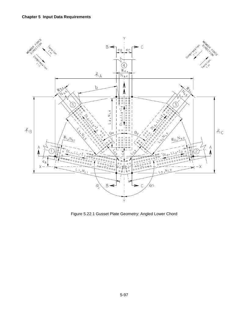
Chapter 5 Input Data Requirements
5-97
Figure 5.22.1 Gusset Plate Geometry: Angled Lower Chord
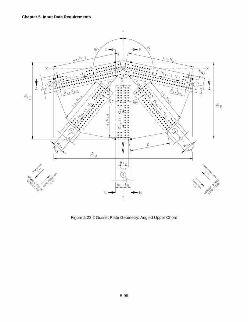
Chapter 5 Input Data Requirements
5-98
Figure 5.22.2 Gusset Plate Geometry: Angled Upper Chord
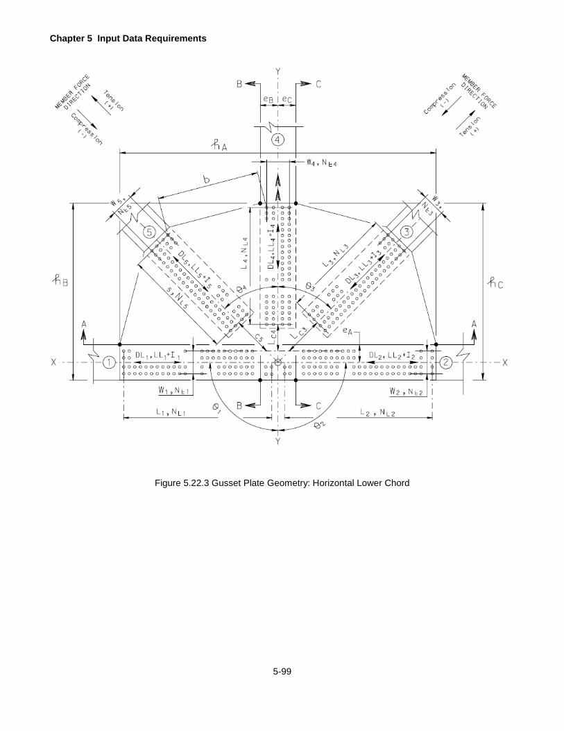
Chapter 5 Input Data Requirements
5-99
Figure 5.22.3 Gusset Plate Geometry: Horizontal Lower Chord

Chapter 5 Input Data Requirements
5-100
Figure 5.22.4 Gusset Plate Geometry: Horizontal Upper Chord
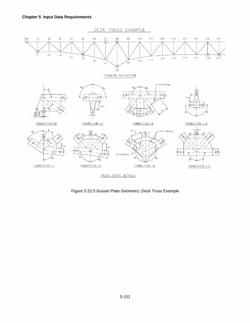
Chapter 5 Input Data Requirements
5-101
Figure 5.22.5 Gusset Plate Geometry: Deck Truss Example

Chapter 5 Input Data Requirements
5-102
GUSSET PLATE MEMBER PROPERTIES
This command is used to input the members connected to the gusset plate. If a member is not present, do not
enter any information for that member. See Figure 5.22.1 on page 5-97 to Figure 5.22.4 on page 5-100 for
explanations of all dimension inputs. This command can be repeated to define members for up to 122 gusset plates
and joints, 61 upper and 61 lower.
If "Y" is entered for GUSSET in the BRIDGE CROSS SECTION AND LOADING line, enter these data only for the
bridge types of "TFF", "TFS", and "TTT"
If "Y" is entered for SYMMETRY in the BRIDGE CROSS SECTION AND LOADING line, you must enter only the
gusset plate member properties for the panels left of the symmetry point.
There may be a maximum of 5 members per joint. Enter the first three members first. If needed, enter the rest of
members into the second line.
At gusset plate locations where the chord is continuous through the gusset plate the fastener dimensions for L1 and
L2 are entered as the total width of the fasteners across both members 1 and 2, i.e. L1 = L2 = L1 + L2 . W1 and W2
should be the same for members 1 and 2. Nt1 and Nt2 should be entered as the sum of the fasteners connecting
members 1 and 2, i.e. Nt1 = Nt2 = (Nt1+Nt2).
GMB CARD IDENT
Enter the identification of this Card, "GMB"
GUSSET PLATE LOC1
Enter the location of the gusset plate members by the joint, "U" or "L".
Note: The program can't handle the gusset plate members at the middle joint, "M".
GUSSET PLATE LOC2
Enter the location of the gusset plate by the joint, 00, 01, 02, ...
Lower Limit: 00 and Upper Limit: 60
TRUSS MEMBER NO
Enter the member number being considered. Member number can't be repeated for the same joint.
Lower Limit: 1 and Upper Limit: 5

Chapter 5 Input Data Requirements
5-103
DISTANCE, W
Enter the distance between outermost rows of fasteners measured perpendicular to the line of action on
the member.
Lower Limit: 0 in and Upper Limit: 60 in.
DISTANCE, L
Enter the distance between the first and last row of fasteners in the member.
Lower Limit: 0 in and Upper Limit: 125 in.
NUMBER OF LINES OF FASTENERS, NT
Enter the number of lines of fasteners along the width of member (perpendicular to the line of action of
the member).
Lower Limit: 0 and Upper Limit: 20.
NUMBER OF ROWS OF FASTENERS, NL
Enter the number of rows of fasteners along the length of member (parallel to the line of action of the
member).
Lower Limit: 0 and Upper Limit: 40.
LENGTH, Lc
Enter the unsupported length between the last row of fasteners for the diagonal and the first row of
fasteners in the chord measured along the line of action of the diagonal, calculated as average per
section 3.11.4.2.
Lc must be 0 for member number 1 and 2 (i.e. top and bottom chords).
Lower Limit: 0 in and Upper Limit: 60 in.
NTT
Enter the total number of fasteners connecting the individual truss member to the gusset plate.

Chapter 5 Input Data Requirements
5-104
CONCENTRATED PATCH LOADS
This command is used to input concentrated patch loads acting on the bridge for one patch load case. If the patch
load is not present, do not enter any information. See Figure 5.24.1 on page 5-106 for explanations of all dimension
inputs. This command can have 4 concentrated patch loads in one line and can be repeated up to 8 times to define
up to 30 concentrated patch loads.
The effects of concentrated patch loads are considered as the effects of dead loads. If you have multiple patch
load cases, then you need to run this program for each patch load case.
A patch load case is defined as the followings:
1. A series of concentrated patch loads
2. A series of distributed patch loads
3. A series of concentrated patch loads and a series of distributed patch loads.
PAC CARD IDENT
Enter the identification of the Card, "PAC"
MEM TYPE
Enter T, G, F, S, or C, where T is for truss member, G is for girder, F is for floorbeam, S is for stringer, and
C is for concrete slab or concrete T-beam
Please note that S are reserved for future use.
LOAD TYPE
Enter the type of dead load left justified per WSD or LFD Specifications:
DC1:
DC1S:
DC2:
MC1: Miscellaneous dead loads
MC2: Miscellaneous dead loads
FWS: Dead loads of future wearing surfaces
OTH1: Other loads
OTH2: Other loads
Note:
1. For DC1, DC1S, MC1, and OTH1 of bridge types other than EIB, non-composite section properties
will be used.
Chapter 5 Input Data Requirements
5-105
2. For DC1, DC1S, MC1, and OTH1 of the EIB unshored construction where COMPOSITE field in the STEEL MEMBER PROPERTIES line is “N” or blank, then non-composite section properties will be used.
3. For DC1, DC1S, MC1, and OTH1 of the EIB shored construction where COMPOSITE field in the STEEL MEMBER PROPERTIES line is “Y”, then DL2 composite section properties will be used.
4. For DC2, FWS, MC2, and OTH2, if the section is not composite, then use non-composite section
properties and if the section is composite, then use long-term composite (3n) section properties.
SPAN NO
If MEM TYPE is T, G, S, or C, enter the span number where the concentrated patch load is located.
Lower Limit: 01 and Upper Limit: 15
If MEM TYPE is F, enter the number of stringer span to the right of the floorbeam (from “1” to “G”) where the concentrated patch load is located.
Lower Limit: 01 and Upper Limit: 16
DISTANCE
If MEM TYPE is T, G, S, or C, enter the distance in feet measured from the left support of this span to the concentrated load. Lower Limit: 0 and Upper Limit: Maximum Span Length If MEM TYPE is F, enter the distance in feet measured from the left girder, truss, or support to the concentrated load.
Note: the distance measured at the left cantilever span is always negative.
Lower Limit: -left cantilever span length and Upper Limit: Main Floorbeam Span Length + Right Cantilever Span Length
MAGNITUDE
Enter the magnitude in kips of the concentrated patch load acing on the bridge.
Lower Limit: -99.99 and Upper Limit: 999.99
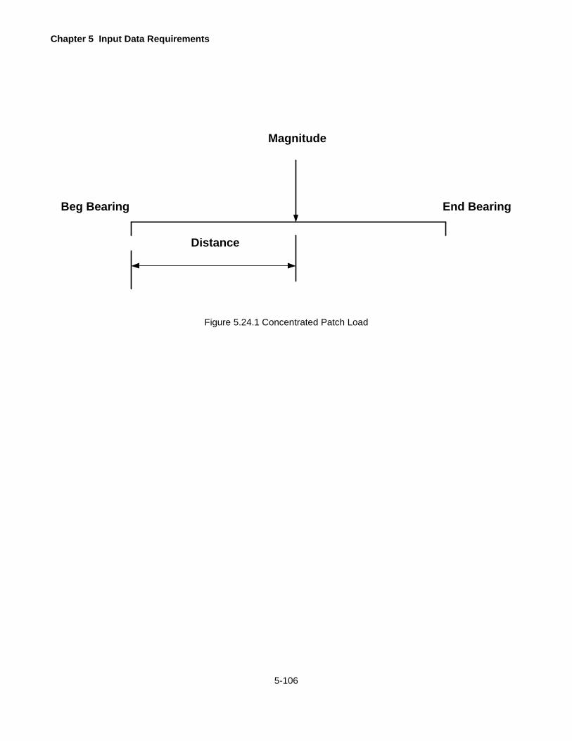
Chapter 5 Input Data Requirements
5-106
Distance
Magnitude
Beg Bearing End Bearing
Figure 5.24.1 Concentrated Patch Load

Chapter 5 Input Data Requirements
5-107
DISTRIBUTED PATCH LOADS
This command is used to input distributed patch loads acting on the bridge for one patch load case. If the patch
load is not present, do not enter any information. See Figure 5.25.1 on page 5-110 for explanations of all dimension
inputs. This command can have 2 distributed patch loads in one line and can be repeated to define up to 30
distributed patch loads.
The effects of distributed patch loads are considered as the effects of dead loads. If you have multiple patch load
cases, then you need to run this program for each patch load case.
PAD CARD IDENT
Enter the identification of the Card, "PAD"
MEM TYPE Enter T, G, F, S, or C, where T is for truss member, G is for girder, F is for floorbeam, S is for stringer, and C is for concrete slab or concrete T-beam Please note that S are reserved for future use.
LOAD TYPE
Enter the type of dead load left justified per WSD or LFD Specifications:
DC1:
DC1S:
DC2:
MC1: Miscellaneous dead loads
MC2: Miscellaneous dead loads
FWS: Dead loads of future wearing surfaces
OTH1: Other loads
OTH2: Other loads
Note: 1. For DC1, DC1S, MC1, and OTH1 of bridge types other than EIB, non-composite section properties
will be used. 2. For DC1, DC1S, MC1, and OTH1 of the EIB unshored construction where COMPOSITE field in the
STEEL MEMBER PROPERTIES line is “N” or blank, then non-composite section properties will be used.
3. For DC1, DC1S, MC1, and OTH1 of the EIB shored construction where COMPOSITE field in the STEEL MEMBER PROPERTIES line is “Y”, then DL2 composite section properties will be used.
4. For DC2, FWS, MC2, and OTH2, if the section is not composite, then use non-composite section properties and if the section is composite, then use long-term composite (3n) section properties.
Chapter 5 Input Data Requirements
5-108
BEG SPAN NO If MEM TYPE is T, G, S, or C, enter the span number where the distributed patch load begins. Lower Limit: 01 and Upper Limit: 15 If MEM TYPE is F, enter the number of stringer span to the right of the floorbeam (from “1” to “G”) where the distributed patch load is located. Lower Limit: 01 and Upper Limit: 16
BEG DISTANCE
If MEM TYPE is T, G, S, or C, enter the distance in feet measured from the left support of this span to the begin location of this distributed patch load. Lower Limit: 0 and Upper Limit: Maximum Span Length If MEM TYPE is F, enter the distance in feet measured from the left girder, truss, or support to the begin location of this distributed patch load. Note: the distance measured at the left cantilever span is always negative. Lower Limit: -left cantilever span length and Upper Limit: Floorbeam Main Span Length + Right Cantilever Span Length
BEG MAGNITUDE
Enter the magnitude in kips of the begin location of the distributed load acing on the bridge.
Lower Limit: -99.999 and Upper Limit: 999.999
END SPAN NO
If MEM TYPE is T, G, S, or C, enter the span number where the distributed patch load ends. Lower Limit: 01 and Upper Limit: 15 If MEM TYPE is F, enter the number of stringer span to the right of the floorbeam (from “1” to “G”) where the distributed patch load is located. Lower Limit: 01 and Upper Limit: 16
Chapter 5 Input Data Requirements
5-109
END DISTANCE
If MEM TYPE is T, G, S, or C, enter the distance in feet measured from the left support of this span to the end location of this distributed patch load. Lower Limit: 0 and Upper Limit: Maximum Span Length If MEM TYPE is F, enter the distance in feet measured from the left girder, truss, or support to the end location of this distributed patch load. Note: the distance measured at the left cantilever span is always negative. Lower Limit: -left cantilever span length and Upper Limit: Floorbeam Main Span Length + Right Cantilever Span Length
END MAGNITUDE
Enter the magnitude in kips of the end location of the distributed patch load acing on the bridge.
Lower Limit: -99.999 and Upper Limit: 999.999
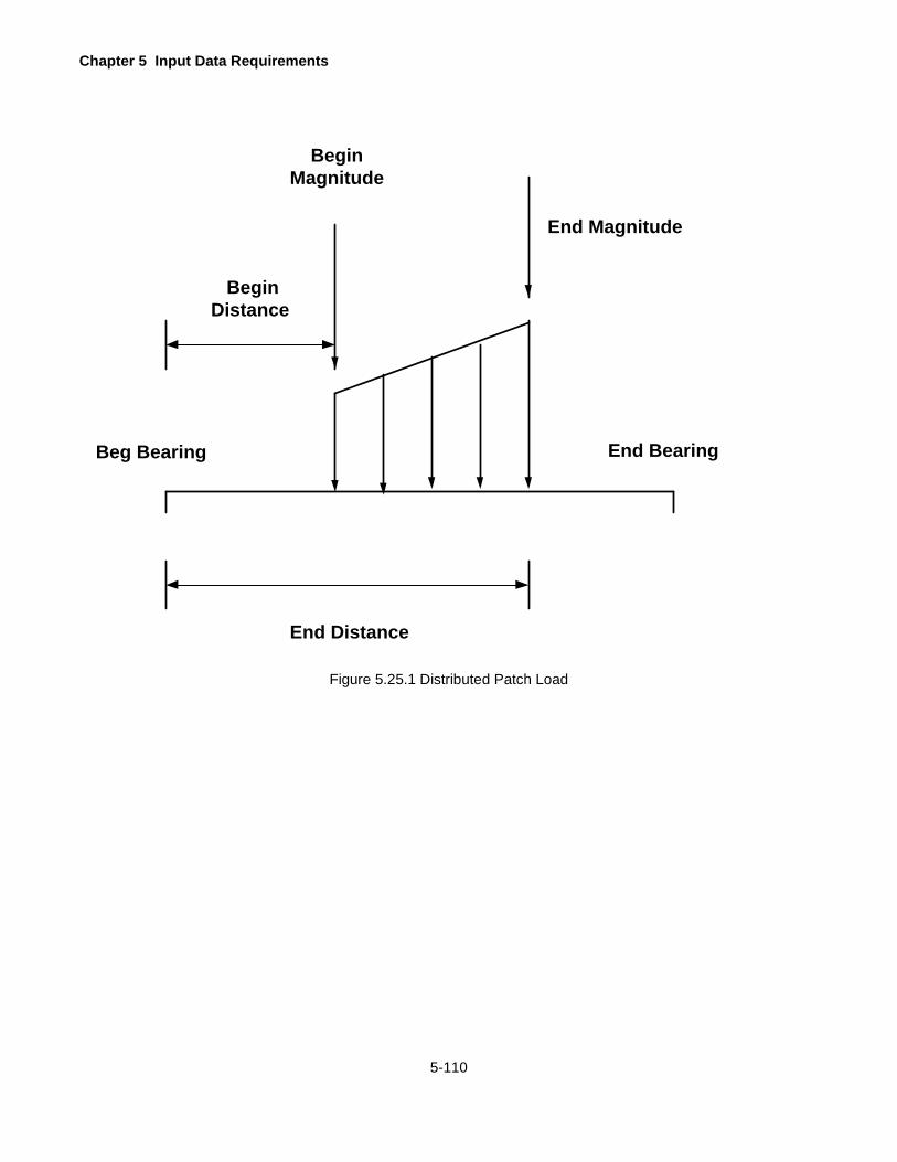
Chapter 5 Input Data Requirements
5-110
End Distance
Begin Magnitude
Beg Bearing End Bearing
BeginDistance
End Magnitude
Figure 5.25.1 Distributed Patch Load

6-1
DESCRIPTION OF OUTPUT
The printed output consists of heading information such as the copyright notice, program title, license agreement
number, program number, date and time of run, date when the program was last updated, documentation date for
the latest revision, and the input name. It also includes a repeat of all input values, default values assumed by the
program, and the computed values explained in the following sections. Only the output that is applicable to a given
type of bridge is printed. Most headings are self-explanatory. The terms IR, OR and SLC refer to the Inventory
Rating, Operating Rating and Safe Load Capacity respectively. Dashes printed under DEFAULT VALUES indicate
that these values were entered. Values replaced by the stars printed indicate these output values is too big for the space allowed.
The following sign conventions apply:
MOMENT
A positive moment causes a compressive stress in the extreme top fiber of a flexural member.
REACTION
A reaction acting in the upward direction is positive.
LOAD
A load acting in the downward direction in positive.
SHEAR
A shearing force acting upward on the right face of the free body in equilibrium is positive.
DEFLECTION
Downward vertical deflection is positive. Horizontal deflection to the right is positive.
FORCE
A truss member force is positive if the member is tension.
STRESS
A tensile stress is positive.

Chapter 6 Description of Output
6-2
These calculated values are printed for each analysis point, range point, and transition (change in section properties) point along the span. The distances of the analysis points are measured from the left end of each
span.
Influence line ordinates for a given effect at a section in the girder or beam are printed in rows, with each row
representing the span (e.g. the first row represents the span 1) and each value representing the effect (moment,
shear, etc.) due to a unit load at a tenth point in that span. Thus, the fourth value in row 2 will represent the influence
line ordinate for a given effect due to a unit load at 3/10 of span number 2.
Influence line ordinates for a truss member force are also printed in the same manner except each row represents
ten (10) consecutive ordinates and the values are the effects due to a unit load at either the upper or lower truss
joints.
Special live loadings are designated as SP-1, SP-2 etc. on the output, where SP-1 is the special live loading 1, SP-
2 is the special live loading 2 and so on. Alternate Military Loading is designated as ALTM on the output.
.

Chapter 6 Description of Output
6-3
BRIDGE TYPE “CPL”, “CSL”, OR “CTB”
If the output option is specified as 0, the following values are printed for each live load.
6.1.1 Concrete Section Properties
DEPTH OF N.A.
The depth to the neutral axis of the section measured from the top of the section excluding the integral
wearing surface - inches.
MOMENT OF INERTIA
The moment of inertia of the section – in4.
SECTION MODULUS CONCRETE
The section modulus of the concrete section – in3.
SECTION MODULUS TENSION STEEL
The section modulus of the tension steel – in3.
SECTION MODULUS COMPRESSION STEEL
The section modulus of the compression steel – in3.
6.1.2 Maximum Reactions
SUPPORT
The support number always started as 1 indicating the left support of the span.
For simple spans:
MAXIMUM REACTIONS - D.L.
The reaction due to DL1 + DL2 - kips.
MAXIMUM REACTIONS - LL+I
The reaction due to live load plus impact - kips.
For continuous spans:
MAXIMUM REACTIONS - D.L.1
The reaction due to DL1 - kips.
MAXIMUM REACTIONS - D.L.2
The reaction due to DL2 - kips.
MAXIMUM REACTIONS - +(LL+I)
The reaction due to live load plus impact - kips.
MAXIMUM REACTIONS - -(LL+I)
The reaction due to live load plus impact - kips.
Chapter 6 Description of Output
6-4
+I.F.
The positive impact factor used for calculating +(LL + I) reaction.
-I.F.
The impact factor used for calculating –(LL + I) reaction.
6.1.3 Moment, Shear, Flexural Stress, Shear Stress, and Deflection at Each Section for Each Live Load
X
The distance of the section from the left support of the span - feet.
D.L. MOMENT
The moment due to DL1 + DL2 - kip-ft.
LL+I MOMENT
The live load plus impact moment - kip-ft.
D.L. SHEAR
The shear due to DL1 + DL2 - kips.
LL+I SHEAR
The live load plus impact shear - kips.
I.F.
The impact factor used for calculating LL + I SHEAR.
FLEX STRESS - CONC
The maximum compressive stress in concrete due to the dead load and live load plus impact - ksi.
FLEX STRESS - STEEL
The maximum tensile stress in reinforcement due to the dead load and live load plus impact - ksi.
SHEAR STRESS - D.L.
The maximum shear stress due to DL1 + DL2 - ksi.
SHEAR STRESS - LL + I
The maximum shear stress due to live load plus impact - ksi.
DEFLECTIONS - D.L.
The maximum deflection due to DL1 + DL2 - inches.
DEFLECTIONS - LL+I
The maximum deflection due to live load plus impact - inches.

Chapter 6 Description of Output
6-5
6.1.4 Moment Capacity, Shear Capacity, and Rating Factors at Each Section for Each Live Load
MOMENT CAPACITY - IR
The maximum allowable moment for the Inventory Rating - kip-ft.
MOMENT CAPACITY - OR
The maximum allowable moment for the Operating Rating - kip-ft.
MOMENT CAPACITY - ULT
The ultimate moment capacity of the section - kip-ft.
SHEAR CAPACITY - IR
The maximum allowable shear for the Inventory Rating - kips.
SHEAR CAPACITY - OR
The maximum allowable shear for the Operating Rating - kips.
SHEAR CAPACITY - ULT
The ultimate shear capacity of the section - kips.
RATING FACTORS
The inventory (IR) and operating (OR) rating factors for moment and shear based on the Allowable Stress
Method and the Load Factor Method. The Rating Factors for the ML80 and TK527 loadings are based on
the axle loads shown in Figure 2.4.1 on page 2-11. The Rating Factors for Special Live Loadings are based
on the entered axle loads increased by 3% if a Y is entered for 3% INCR described in Section 4.18.1 of this
User’s Manual.
6.1.5 Moment Capacity, Shear Capacity, and Rating Factors at Critical Sections for Each Live Load
If the output option is specified as 2, the values in 6.1.5 will be printed at critical sections for moments and
shears.
6.1.6 Rating Summary
The rating summary is printed showing the rating factor, rating in tons and critical section for each live load.
It also shows if the ratings are based on design lanes or loaded lanes and prints the safe load capacity
(SLC) of the member if it was requested. The ratings in tons for the ML80 and TK527 loadings do not
include the 3% scale tolerance allowed by the Vehicle Code. The ratings in tons for a Special Live loading
do not include the 3% increase in the entered axle loads.

Chapter 6 Description of Output
6-6
6.1.7 Influence Line
If the output option is specified as 9 to print influence lines, the following values are printed for a given live load.
INFLUENCE LINE FOR REACTION AT SUPPORT 1
The influence line ordinates for reactions at the left support due to a unit load (1 kip) applied at 10th points
- kips.
POS AREA
The sum of positive area under influence line.
NEG AREA
The sum of negative area under influence line.
LANE POS
The maximum positive effect of an equivalent lane loading, if applicable.
LANE NEG
The maximum negative effect of an equivalent lane loading, if applicable.
TRUCK POS
The maximum positive effect of a truck loading.
AXLE 1 @
The distance of axle number 1 (the front axle) from the left support of span to produce the given maximum
effect - feet.
MOVING
Indicates the direction in which the truck is moving. L TO R indicates that the truck is moving from left to
right. R TO L indicates that the truck is moving from right to left.
TRUCK NEG
The maximum negative effect of a truck loading.
SUPPORT, MAXIMUM REACTIONS - DL, LL+I
These values are the same as explained for the output option equal to 0.
For each section the following values are printed.
SECTION NUMBER
Self-explanatory.
INFLUENCE LINE FOR MOMENT
The influence line ordinates for moments at a section due to a unit load (1 kip) applied at 10th points - kip-
ft.

Chapter 6 Description of Output
6-7
INFLUENCE LINE FOR SHEAR
The influence line ordinates for shears at a section due to a unit load (1 kip) applied at 10th points - kips.
When a unit load is applied at the section under consideration there should be two values of shears to be
considered, one for a unit load just to the left of the section (negative shear) and another for a unit load just
to the right of the section (positive shear). The program stores and prints the negative value of shear
ordinates. The positive ordinate can be obtained by algebraically adding the value of unit load and the
negative ordinate.
INFLUENCE LINE FOR DEFLECTION
The influence line ordinates for deflections at a section due to 1000 kip applied at the 10th points - inches.
Chapter 6 Description of Output
6-8
BRIDGE TYPE "EIB" OR "GGG"
The following values are printed for this type of bridge.
6.2.1 Dead Loads Acting on Girder
This is the individual dead loads acting on the girder. Some values are input and some values are computed
by the program.
INPUT DL1
The dead load acting on the non-composite section - kips/ft. This is equal to the input value as entered in
the BRIDGE CROSS SECTION AND LOADING line.
GIRDER WEIGHT
The average weight of girder, i.e. the total weight of one girder divided by its length - kips/ft.
SLAB WEIGHT
The dead load due to the weight of slab - kips/ft.
FL BEAM WEIGHT
The dead load due to the weight of floorbeam acting as a uniformly distributed load - kips/ft. This is printed
as zero for this bridge type.
STRINGER WEIGHT
The dead load due to the weight of stringer - kips/ft. This is printed as zero for this bridge type.
TOTAL DL1
The total dead load acting on the non-composite section - kips/ft.
This is equal to the sum of INPUT DL1, GIRDER WEIGHT and SLAB WEIGHT.
TOTAL DL2
The total dead load acting on the composite section - kips/ft.
This is equal to the input value as entered in the BRIDGE CROSS SECTION AND LOADING line.
6.2.2 Girder Section Properties
The following are printed for each span when the output option is specified as 0.
6.2.2.1 Non-Composite Section Properties
The section properties for steel section alone. The DL1 effects are carried by this section.
X
The distance of the section from the centerline of left bearing of the span where this section is located -
feet.

Chapter 6 Description of Output
6-9
DEPTH
The total depth of the section - inches.
AREA
The gross cross sectional area of the section – in2.
M OF I
The moment of inertia about the neutral axis of the section – in4.
C BOT
The distance of the extreme bottom fiber from the neutral axis - inches.
S TOP
The section modulus (ratio of moment of inertia to distance of extreme fiber from the neutral axis) of the
extreme top fiber – in3. This value may be negative if the neutral axis is outside the steel beam.
S BOT
The section modulus of the extreme bottom fiber – in3.
S CONC
The section modulus of the extreme top fiber of concrete for a composite section subjected to a positive
moment – in3.
S REIN
The section modulus of the center of gravity of tension reinforcement for a composite section subjected to
a negative moment - in3.
6.2.2.2 Composite Section Properties (N=xx)
The section properties of the composite section with a modular ratio of n as printed. The live load plus
impact effects are carried by this section.
EFFECTIVE SLAB WIDTH, THICKNESS
The effective width and thickness of the slab used in calculating the composite section properties - inches.
6.2.2.3 Composite Section Properties (3N=xx)
The section properties of the composite section with a modular ratio of 3n as printed. The DL2 effects are
carried by this section.
6.2.2.4 Composite Section Properties (Composite, Negative Moment)
The section properties of the composite section if the concrete slab does not carry tensile stress and the
slab reinforcement acts compositely with the steel section. Negative moments caused by the dead load
combined with maximum negative live load plus impact are carried by this section.
Chapter 6 Description of Output
6-10
6.2.3 Deflections
The following are printed for each span when the output option is specified as 0.
DEFLECTIONS
The deflections at analysis points.
SPAN X - LIVE LOAD IMPACT FACTOR FOR DEFLECTION
Self-explanatory.
X
The distance of the analysis point from the left bearing of the span - feet.
DEFLECTIONS DL1, DL2, +(LL+I)
The deflections due to DL1, DL2 and live load plus impact respectively - in. A negative value indicates a
upward deflection.
6.2.4 Girder – Live Load Xxxx
The following are printed for each live load when the output option is specified as 0.
6.2.4.1 Maximum Reactions
SUPPORT
This is the support number. If the girder is continuous, reactions for all supports are printed. If the girder
is a single span or a series of simple spans, the reactions are printed for the left support in each span.
MAXIMUM REACTIONS - DL1, DL2, +(LL+I), Lane Loading Code, -(LL+I), Lane Loading Code, Reaction +I.F. and
-I.F., and Moment +I.F. and -I.F.
The reactions due to DL1 and DL2, positive live load plus impact reaction and the impact factor for positive
reaction, and the negative live load plus impact reaction (uplift) and the impact factor for negative reaction.
For HS loading, if the reaction is governed by the lane loading, the code "L" is printed next to the value. If
"L" is not printed, it is assumed that the truck loading governs. Live load plus impact is in kips. Also, the
impact factors used for positive and negative moments at interior supports.
For each span, the following values are printed for all sections. If SYMMETRY is entered as "Y", these values are
printed up to the point of symmetry.
6.2.4.2 Unfactored Moments and Shears
The moments and shears at 10th points along the span.
SPAN X - LIVE LOAD IMPACT FACTORS
The positive moment impact factor for this span based on "L" equal to the length of this span. Up to three
negative moment impact factors for this span based on "L" equal to the loaded span (previous span, this
Chapter 6 Description of Output
6-11
span, or the next span) for the given tenth point. If there is more than one negative moment impact factor,
a code will be printed next to the negative moment value to indicate which of the listed negative moment
impact factors (1, 2 or 3) is used at that tenth point.
X
The distance of the section from the left support of the span - feet.
DL1 MOMENT
The moment due to DL1 - kip-ft.
DL2 MOMENT
The moment due to DL2 - kip-ft.
+(LL+I) MOMENT
The maximum positive moment due to the live load plus impact - kip-ft.
For HS loading, if the moment is governed by the lane loading, the code "L" is printed. If "L" is not printed,
it is assumed that the truck loading governs.
-(LL+I) MOMENT
The maximum negative moment due to the live load plus impact - kip-ft.
IM
For HS loading, if the moment is governed by the lane loading, the code "L" is printed. If "L" is not printed,
it is assumed that the truck loading governs. If this is a tenth point and there is more than one negative
moment impact factor listed for this span, a code is printed next to this value to indicate which of the negative
moment impact factors is used (1, 2 or 3) for this point. If this is not a tenth point, the moment value is
interpolated from the calculated tenth point values. If this is a support point for a continuous girder, an "S"
code is printed to indicate that the negative moment impact factor calculated for the support is used.
Continuous girder moment impact factors for the supports are listed with the Maximum Reactions.
DL1 SHEAR
The shear due to DL1 - kips. All shear values (including DL2 and LL+I) are for a section just to the right of
a given section except for all intermediate support sections and the rightmost support section, where the
shear values are for a section just to the left of the given section.
DL2 SHEAR
The shear due to DL2 - kips.
+(LL+I) SHEAR
The maximum positive shear due to the live load plus impact - kips.
-(LL+I) SHEAR
The maximum negative shear due to the live load plus impact - kips.
Chapter 6 Description of Output
6-12
I.F.
The impact factor used in calculating +(LL+I) SHEAR and -(LL+I) SHEAR.
SIMULTANEOUS MOMENT
The moment that occurs simultaneously with the maximum shear at a section - kip-ft. This is used in
calculating the rating factor for moment-shear interaction.
SIMULTANEOUS SHEAR
The shear that occurs simultaneously with the maximum moment at a section - kips. This is used in
calculating the rating factor for moment-shear interaction.
6.2.4.3 Flexural Stresses - Beam
The extreme fiber stresses at analysis points.
TOP FIBER STEEL STRESS - DL1, DL2, +(LL+I), -(LL+I)
The maximum stress at the top fiber of steel section due to DL1 moment, DL2 moment, positive live load
plus impact moment, and negative live load plus impact moment respectively - ksi.
BOTTOM FIBER STEEL STRESS - DL1, DL2, +(LL+I), -(LL+I)
The maximum stress at the bottom fiber of steel section due to DL1 moment, DL2 moment, positive live
load plus impact moment, and negative live load plus impact moment respectively - ksi.
6.2.4.4 Flexural Stresses – Slab
CONC STRESS - DL2, +(LL+I)
The maximum compressive stress in the top fiber of concrete for a composite section due to DL2 and
positive live load plus impact moments respectively - ksi.
SLAB REINF STRESS - DL2, -(LL+I)
The maximum tensile stress in the reinforcement due to DL2 and negative live load plus impact moments
respectively - ksi.
6.2.4.5 Shear Stresses and Allowable Stress Ratings
The shear stresses and rating factors based on the Allowable Stress Method.
SHEAR STRESSES - DL1, DL2, +(LL+I), -(LL+I)
The maximum shear stress in the web due to DL1, DL2, positive live load plus impact and negative live
load plus impact shear respectively - ksi.
ALLOWABLE COMPRESSION REDUCTION
The reduction factor for allowable compression in a partially supported or unsupported compression flange.
This factor when multiplied by 0.55 Fy. and 0.75 Fy. gives the allowable stresses for the Inventory and
Operating ratings respectively.

Chapter 6 Description of Output
6-13
RATING FACTORS - IR, OR
The inventory and operating rating factors at an analysis point based on the Allowable Stress Method.
RATING FACTOR CODE
See legend on the output.
6.2.4.6 Strengths and Load Factor Ratings
The section strengths and rating factors at an analysis point.
NON-COMP MOMENT STRENGTH
The moment strength of the non-compact section - kip-ft.
NON-COMP MOMENT STRENGTH CODE
Section qualification, i.e. whether it is braced non-compact (B) or unbraced non-compact (U) as per
AASHTO Specifications.
OVERLOAD MOMENT STRENGTH
The overload moment strength of the section - kip-ft.
SHEAR STRENGTH
The shear strength of the section - kips.
NON-COMPACT RATING FACTORS - IR, OR
The inventory and operating rating factors at an analysis point based on the Load Factor Method, assuming
that the section is non-compact. If any section does not qualify as compact, then the summary will reflect
the lowest non-compact rating factor.
NOTE: When a section does not meet flange or web buckling criteria of the current AASHTO Specifications for
load factor method, the section is identified by printing a rating factor of 888.88. For these sections, the ratings
based on strength only are also printed out, but the bridge may have fatigue problems.
NON-COMPACT RATING FACTOR CODE
See the legend on the output.
COMPACT MOMENT STRENGTH
For a section that qualifies as compact, the compact moment strength - kip-ft. For a non-compact section
this is blank.
COMPACT RATING FACTORS - IR, OR
For a section that qualifies as compact, the inventory and operating rating factors at an analysis point based
on the Load Factor Method, assuming that the section is compact. For a non-compact section this is blank.
COMPACT RATING FACTOR CODE
See the legend on the output.
Chapter 6 Description of Output
6-14
6.2.5 Fatigue Life Analysis
Based on HS20 truck loading with fixed (14.0 feet) spacing between 32-kip axles.
6.2.5.1 Unfactored Moments and Shears
The unfactored moments and shears at 10th points along the span.
6.2.5.2 Fatigue Life Estimation
FATIGUE LIFE ESTIMATION
The following values are printed if the fatigue life analysis is requested for the girder.
LIVE LOAD DISTRIBUTION
The live load distribution factor (fraction of axle loads) for loading one lane that is used for calculating the
fatigue stress range.
PA TRAFFIC FACTOR
The Pennsylvania Traffic Factor (PTF) that is used in calculating the effective stress range for the fatigue
life equation. This value is 1.0 for ADTT less than or equal to 2500 (Case II or III Highways) and it is equal
to 1.1 for ADTT greater than 2500 (Case I Highways).
ALPHA FACTOR
The alpha factor that is used in calculating the effective stress range for the fatigue life equation. This is
equal to 0.5 since the program uses the conventional method of structural analysis.
GAMMA FACTOR
The gamma factor that is used in calculating the effective stress range for the fatigue life equation. This is
equal to 0.7 times the Pennsylvania Traffic Factor (PTF) if the Gross Vehicle Weight Distribution data are
not entered. This is the calculated value as per DM4 if the Gross Vehicle Weight Distribution data are
entered.
PAST GROWTH FACTOR or PAST CONSTANT ADTT
The growth factor for past ADTT in percent or the constant ADTT for the past.
FUTURE GROWTH FACTOR or FUTURE CONSTANT ADTT
The growth factor for future ADTT in percent or the constant ADTT for the future.
X
The horizontal distance from the left centerline of bearing of the span to the section where this detail is
located - feet.
Y
The vertical distance of the detail from the bottom most fiber at this section - inches.
CATEGORY
The stress category of detail as entered.

Chapter 6 Description of Output
6-15
DL1+DL2 STRESS
The stress at this detail due to DL1+DL2 - ksi.
HS20 TRK STRESS +(LL+I)
The stress at this detail caused by the maximum positive live load plus impact moment due to an HS20
truck loading. This value is based on the distribution factor for one lane - kip-ft.
HS20 TRK STRESS -(LL+I)
The stress at this detail caused by the maximum negative live load plus impact moment due to an HS20
truck loading. This value is based on the distribution factor for one lane - kip-ft.
STRESS RANGE - FSRD
The design fatigue stress range calculated using the live load distribution factor for one lane - ksi. The
value printed here is an algebraic difference of the maximum and the minimum stresses due to dead loads
and live load plus impact at this detail due to an HS20 truck placed in one lane. If the detail never
experiences a tensile stress, i.e. if the maximum and minimum stresses at this detail are compressive, the
fatigue stress range is assumed to be zero.
STRESS RANGE - FSR
The allowable fatigue stress range for cycles greater than 2,000,000 for the above category of detail - ksi.
STRESS RANGE - FSRE
The effective fatigue stress range as defined in DM4 - ksi. This value is equal to the design fatigue stress
range due to an HS20 truck in one lane multiplied by the ALPHA FACTOR and GAMMA FACTOR printed
above. If FSRD is zero or is less than FSR, this is printed as zero indicating that the detail has infinite
fatigue life.
DES FATIGUE LIFE CYCLES
The fatigue life in terms of cumulative truck cycles (number of times a design truck may pass over the
bridge). If FSR is greater than FSRD or if FSRD is zero, this is printed as 9999999999 signifying that the
detail has infinite fatigue life.
REMAIN YEARS
The remaining fatigue life of the detail - years.
The location of critical detail, estimated ADTT for the year the bridge was built, design fatigue life of the
critical detail, accumulated cycles and estimated remaining life of the girder are printed next. If the fatigue life is infinite, “THE FATIGUE LIFE OF GIRDER IS INFINITE.” Is printed

Chapter 6 Description of Output
6-16
6.2.6 Rating Summary
The rating summary is printed showing the rating factor, rating in tons and critical section for each live load.
It also shows if the ratings are based on design lanes or loaded lanes and prints the safe load capacity
(SLC) of the member if it was requested. The ratings in tons for the ML80 and TK527 loadings do not
include the 3% scale tolerance allowed by the Vehicle Code. The ratings in tons for a Special Live loading
do not include the 3% increase in the entered axle loads. When COMPACT in PROJECT IDENTIFICATION is “Y” or blank, rating summary follows the all-or-none compact section requirements:
If all sections in all spans are qualified as compact sections, then the summary will reflect the lowest rating factor from all individual compact section ratings. If one or more sections are not qualified as compact sections, then the summary will reflect the lowest rating factor from all individual non-compact section ratings even if some sections by itself would be qualified as compact sections.
When COMPACT in PROJECT IDENTIFICATION is “N”, rating summary does not follow the all-or-none compact section requirements:
If all sections in all spans are qualified as compact sections, then the summary will reflect the lowest rating factor from all individual compact section ratings. If one or more sections do not qualify as compact sections, then the summary will reflect the lowest rating factor from all individual compact section ratings if qualified as a compact section and all individual non-compact section rating if not qualified as a compact section.
The critical section, its location and rating factors are printed for each live load for the girder and the critical stringer. All headings are self-explanatory except the following:
IR (CRITICAL)
The absolute minimum Inventory Rating for the member. It could be based on moment, shear or moment-shear interaction.
OR (CRITICAL) The absolute minimum Operating Rating for the member. It could be based on moment, shear or moment-shear interaction.
IR (POS MOM) The minimum Inventory Rating for the member based on the positive moment.
OR (POS MOM) The minimum Operating Rating for the member based on the positive moment.

Chapter 6 Description of Output
6-17
IR (NEG MOM) The minimum Inventory Rating for the member based on the negative moment.
OR (NEG MOM) The minimum Operating Rating for the member based on the negative moment.
Note: All ratings are based on the number of design lanes or the actual traffic lanes as defined by "D" or "L" entered for LANES in the Project Identification line.
6.2.7 Influence Line
The following values are printed when influence lines are requested.
INFLUENCE LINE FOR MOMENT
The influence line ordinate for moment at a section due to a unit load applied at a 10th point of the span -
kip-ft. The values printed are the influence line ordinate followed by the unit load position (printed in
parenthesis). The unit load position is printed in the form "s.n", where s is the span number and n is the
tenth point in that span. This explanation applies to all influence line values. The units of the values
correspond to the type of the influence line.
POS AREA
The sum of positive area under influence line.
NEG AREA
The sum of negative area under influence line.
LANE POS
The maximum positive effect of an equivalent lane loading, if applicable.
LANE NEG
The maximum negative effect of an equivalent lane loading, if applicable.
TRUCK POS
The maximum positive effect of a truck loading.
AXLE 1 @
The distance of axle number 1 (the front axle) from the left support of span 1 to produce the given maximum
effect - feet.
MOVING
Indicates the direction in which the truck is moving. L TO R indicates that the truck is moving from left to
right. R TO L indicates that the truck is moving from right to left.

Chapter 6 Description of Output
6-18
TRUCK NEG
The maximum negative effect of a truck loading.
INFLUENCE LINE FOR SHEAR
The influence line ordinate for shear at a section due to a unit (1 kip) load applied at each 10th point - kips.
At a given section there should be two values of shear influence line ordinates, one for a unit load just to
the left of the section and another for a unit load just to the right of the section. The program stores and
prints the shear value (negative shear) for a unit load just to the left of the section under consideration. The
program computes the ordinate just to the right of the section when it analyzes the influence line for a given
live load effect.
INFLUENCE LINE FOR DEFLECTION
The influence ordinate for a deflection in inches at a section due to 1000 kips applied at each 10th point.
Chapter 6 Description of Output
6-19
BRIDGE TYPE "FSS”, GFF", "GFS", OR "GGF"
After the printout of all input values, the following computed values are printed. The values for the girder of bridge
type "GGF" are the same as shown for bridge type "GGG".
6.3.1 Girder Analysis
6.3.1.1 Live Load Distribution Factors
LIVE LOAD DISTRIBUTION FACTORS BASED ON DESIGN LANES
The lateral live load distribution factors (including the reduction in live load intensity) based on loading the
design lanes. The number of design lanes and their placements are done in accordance with AASHTO to
produce the maximum effect. These factors are used in calculating the live load effects that are used to
calculate the ratings IR (DESIGN) and OR (DESIGN).
LIVE LOAD DISTRIBUTION FACTORS BASED ON LOADED LANES
The live load distribution factors based on the traffic lanes that are defined by the user. These factors are
used in calculating the live load effects that are used to calculate the ratings IR (LOADED) and OR
(LOADED).
GIRDER MOMENT
The fraction of an axle load (or lane) to be applied for computations of live load moments and shears in the
main girder, and the number of governing lanes (printed in parenthesis) for reduction in live load intensity.
GIRDER DEFLECTION
The fraction of an axle load (or lane) to be applied for the computation of live load deflection of the main
girder, and the number of governing lanes (printed in parenthesis) for reduction in live load intensity.
6.3.1.2 Dead Loads Acting On Girder
The individual dead loads acting on the girder. Some values are input and some values are computed by
the program.
INPUT DL1
The dead load acting on the non-composite section - kips/ft. This is equal to the input value as entered in
the DL1 of the BRIDGE CROSS SECTION AND LOADING line.
GIRDER WEIGHT
The average weight of girder, i.e. the total weight of one girder divided by its length - kips/ft.
SLAB WEIGHT
The dead load due to the weight of slab - kips/ft.

Chapter 6 Description of Output
6-20
FL BEAM WEIGHT
The dead load due to the weight of floorbeam acting as a uniformly distributed load - kip/ft. This is equal to
one-half of the weight of one floorbeam divided by the average floorbeam spacing.
STRINGER WEIGHT
The dead load due to the weight of stringer - kips/ft. This is equal to one-half of the number of stringers in
the bridge cross section multiplied by the weight of stringer per foot.
TOTAL DL1
The total dead load acting on the non-composite section - kips/ft. This is equal to the sum of INPUT DL1,
GIRDER WEIGHT, FLOORBEAM WEIGHT, STRINGER WEIGHT, and SLAB WEIGHT.
TOTAL DL2
The total dead load acting on the composite section - kips/ft. This is equal to the input value as entered in
the DL2 of the BRIDGE CROSS SECTION AND LOADING line.
6.3.1.3 Main Girder
The tables of section properties, reactions, moments, shears, stresses, strengths, deflections, ratings, and fatigue
analysis are then printed for the main girder. The output looks identical to that given for the bridge type "GGG".
6.3.2 Stringer Analysis
Next, similar tables are printed for the critical stringer if the bridge type is "GFS". For the bridge type "GFF", these
values are not printed.
6.3.3 Floorbeam Analysis
Similar tables are printed for each floorbeam in the same sequence of input. The distance of the analysis point
is measured from the centerline of the left girder, truss, or support. This distance is negative if the analysis point is
on the overhang portion of the left cantilever floorbeam.
6.3.3.1 Floorbeam Span Information
LEFT CANTILEVER
The distance is measured between the centerline of the left girder, truss, or support and the end of the
left cantilever - ft.
FLOORBEAM MAIN SPAN
The distance is measured between the centerline of the left girder, truss, or support and right support - ft.
RIGHT CANTILEVER
The distance is measured between the centerline of the right girder, truss, or support and the end of the
right cantilever - ft.
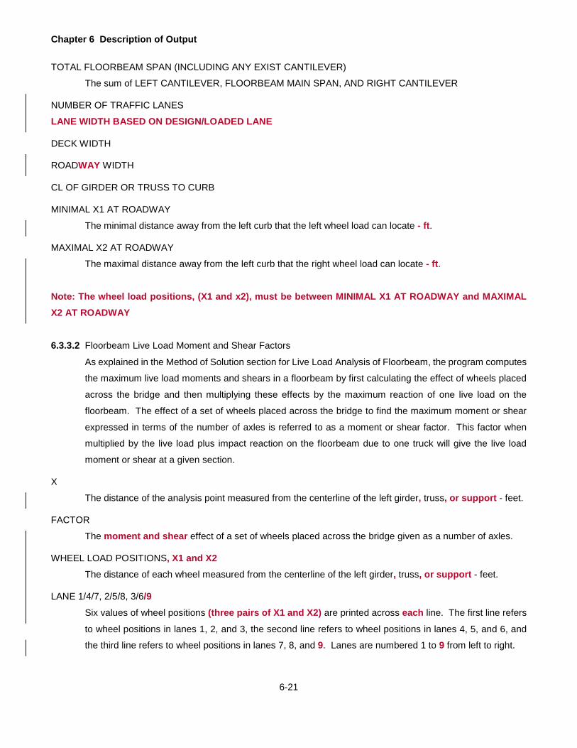
Chapter 6 Description of Output
6-21
TOTAL FLOORBEAM SPAN (INCLUDING ANY EXIST CANTILEVER)
The sum of LEFT CANTILEVER, FLOORBEAM MAIN SPAN, AND RIGHT CANTILEVER
NUMBER OF TRAFFIC LANES LANE WIDTH BASED ON DESIGN/LOADED LANE
DECK WIDTH
ROADWAY WIDTH
CL OF GIRDER OR TRUSS TO CURB
MINIMAL X1 AT ROADWAY
The minimal distance away from the left curb that the left wheel load can locate - ft.
MAXIMAL X2 AT ROADWAY
The maximal distance away from the left curb that the right wheel load can locate - ft.
Note: The wheel load positions, (X1 and x2), must be between MINIMAL X1 AT ROADWAY and MAXIMAL X2 AT ROADWAY
6.3.3.2 Floorbeam Live Load Moment and Shear Factors
As explained in the Method of Solution section for Live Load Analysis of Floorbeam, the program computes
the maximum live load moments and shears in a floorbeam by first calculating the effect of wheels placed
across the bridge and then multiplying these effects by the maximum reaction of one live load on the
floorbeam. The effect of a set of wheels placed across the bridge to find the maximum moment or shear
expressed in terms of the number of axles is referred to as a moment or shear factor. This factor when
multiplied by the live load plus impact reaction on the floorbeam due to one truck will give the live load
moment or shear at a given section.
X
The distance of the analysis point measured from the centerline of the left girder, truss, or support - feet.
FACTOR
The moment and shear effect of a set of wheels placed across the bridge given as a number of axles.
WHEEL LOAD POSITIONS, X1 and X2
The distance of each wheel measured from the centerline of the left girder, truss, or support - feet.
LANE 1/4/7, 2/5/8, 3/6/9
Six values of wheel positions (three pairs of X1 and X2) are printed across each line. The first line refers
to wheel positions in lanes 1, 2, and 3, the second line refers to wheel positions in lanes 4, 5, and 6, and
the third line refers to wheel positions in lanes 7, 8, and 9. Lanes are numbered 1 to 9 from left to right.

Chapter 6 Description of Output
6-22
6.3.3.3 Floorbeam Section Properties
Section properties for each analysis points and range points (except the points at left support (0’) and right support) are printed. When the moment capacity of the current range of a not varied and non-uniform section is less than the moment capacity of the next range, it is conservative to use the section properties of the next range to replace the section properties of the current range.
6.3.3.4 Dead Loads Acting on Floorbeam
The uniform and concentrated dead loads (separated as DL1 and DL2) acting on the floorbeam - kips/ft
and kips, respectively.
DIST
The distance of the concentrated load (usually at stringer line) measured from the centerline of the left
girder or truss - feet.
6.3.3.5 Floorbeam - Live Load Xxxx
The following are printed for each live load when the output option is specified as 0.
LIVE LOAD REACTION FROM DECK (ONE TRUCK)
The maximum live load reaction on the floorbeam by moving one truck in the longitudinal direction (parallel
to main girder or truss) - kips. This reaction when multiplied by the impact factor and the floorbeam live load
moment and shear factors will give the live load moment and shear at a given point on the floorbeam. The
word LANE is printed in place of TRUCK if the lane loading governs for an H or HS loading.
LIVE LOAD IMPACT FACTOR The impact factors for positive and negative moment are listed.
For each span, the following values are printed for all sections. If SYMMETRY is entered as "Y", these values are printed up to the point of symmetry. 6.3.3.5.1 Unfactored Moments and Shears
The moments and shears at 10th points and range points along the span.
SPAN X - LIVE LOAD IMPACT FACTORS The positive moment impact factor for this span based on "L" equal to the length of this span. Up to three negative moment impact factors for this span based on "L" equal to the loaded span (previous span, this span, or the next span) for the given tenth point. If there is more than one negative moment impact factor, a code will be printed next to the negative moment value to indicate which of the listed negative moment impact factors (1, 2 or 3) is used at that tenth point.
X The distance of the section from the left girder, truss, or support of the span - feet.

Chapter 6 Description of Output
6-23
RANGE POINT INDICATOR Indicator whether is a range point or an analysis point
R: it is only a range point B: it is both a range point and an analysis point
DL1 MOMENT The moment due to DL1 - kip-ft.
DL2 MOMENT The moment due to DL2 - kip-ft.
LL+I MOMENT The maximum positive or negative moment due to the live load plus impact - kip-ft. For HS loading,
DL1 SHEAR The shear due to DL1 - kips. All shear values (including DL2 and LL+I) are for a section just to the right of a given section except for all intermediate support sections and the rightmost support section, where the shear values are for a section just to the left of the given section.
DL2 SHEAR The shear due to DL2 - kips.
LL+I SHEAR The maximum positive or negative shear due to the live load plus impact - kips.
I.F. The impact factor used in calculating LL+I SHEAR.
6.3.3.5.2 Flexural Stresses - Beam The extreme fiber stresses at analysis points.
TOP FIBER STEEL STRESS - DL1, DL2, +(LL+I), -(LL+I) The maximum stress at the top fiber of steel section due to DL1 moment, DL2 moment, positive live load plus impact moment, and negative live load plus impact moment respectively - ksi.
BOTTOM FIBER STEEL STRESS - DL1, DL2, +(LL+I), -(LL+I) The maximum stress at the bottom fiber of steel section due to DL1 moment, DL2 moment, positive live load plus impact moment, and negative live load plus impact moment respectively - ksi.
6.3.3.5.3 Flexural Stresses – Slab
CONC STRESS - DL2, +(LL+I) The maximum compressive stress in the top fiber of concrete for a composite section due to DL2 and positive live load plus impact moments respectively - ksi.

Chapter 6 Description of Output
6-24
SLAB REINF STRESS - DL2, -(LL+I) The maximum tensile stress in the reinforcement due to DL2 and negative live load plus impact moments respectively - ksi.
6.3.3.5.4 Shear Stresses And Allowable Stress Ratings The shear stresses and rating factors based on the Allowable Stress Method.
SHEAR STRESSES - DL1, DL2, +(LL+I), -(LL+I) The maximum shear stress in the web due to DL1, DL2, positive live load plus impact and negative live load plus impact shear respectively - ksi.
ALLOWABLE COMPRESSION REDUCTION The reduction factor for allowable compression in a partially supported or unsupported compression flange. This factor when multiplied by 0.55 Fy. and 0.75 Fy. gives the allowable stresses for the Inventory and Operating ratings respectively.
RATING FACTORS - IR, OR The inventory and operating rating factors at an analysis point based on the Allowable Stress Method.
RATING FACTOR CODE See legend on the output.
6.3.3.5.5 Strengths and Load Factor Ratings The section strengths and rating factors at an analysis point.
NON-COMP MOMENT STRENGTH The moment strength of the non-compact section - kip-ft.
NON-COMP MOMENT STRENGTH CODE Section qualification, i.e. whether it is braced non-compact (B) or unbraced non-compact (U) as per AASHTO Specifications.
OVERLOAD MOMENT STRENGTH The overload moment strength of the section - kip-ft.
SHEAR STRENGTH The shear strength of the section - kips.
NON-COMPACT RATING FACTORS - IR, OR The inventory and operating rating factors at an analysis point based on the Load Factor Method, if the section is non-compact. If any section does not qualify as compact, then the summary will reflect the lowest non-compact rating factor.
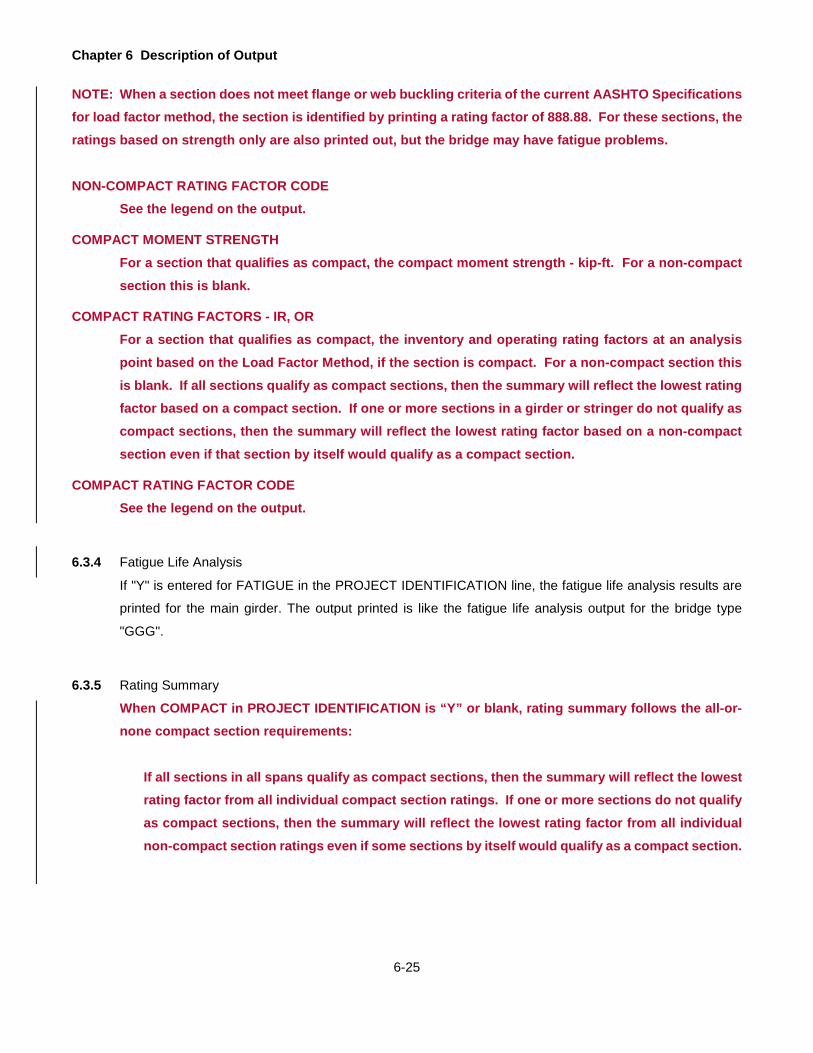
Chapter 6 Description of Output
6-25
NOTE: When a section does not meet flange or web buckling criteria of the current AASHTO Specifications for load factor method, the section is identified by printing a rating factor of 888.88. For these sections, the ratings based on strength only are also printed out, but the bridge may have fatigue problems. NON-COMPACT RATING FACTOR CODE
See the legend on the output.
COMPACT MOMENT STRENGTH For a section that qualifies as compact, the compact moment strength - kip-ft. For a non-compact section this is blank.
COMPACT RATING FACTORS - IR, OR For a section that qualifies as compact, the inventory and operating rating factors at an analysis point based on the Load Factor Method, if the section is compact. For a non-compact section this is blank. If all sections qualify as compact sections, then the summary will reflect the lowest rating factor based on a compact section. If one or more sections in a girder or stringer do not qualify as compact sections, then the summary will reflect the lowest rating factor based on a non-compact section even if that section by itself would qualify as a compact section.
COMPACT RATING FACTOR CODE See the legend on the output.
6.3.4 Fatigue Life Analysis
If "Y" is entered for FATIGUE in the PROJECT IDENTIFICATION line, the fatigue life analysis results are
printed for the main girder. The output printed is like the fatigue life analysis output for the bridge type
"GGG".
6.3.5 Rating Summary
When COMPACT in PROJECT IDENTIFICATION is “Y” or blank, rating summary follows the all-or-none compact section requirements:
If all sections in all spans qualify as compact sections, then the summary will reflect the lowest rating factor from all individual compact section ratings. If one or more sections do not qualify as compact sections, then the summary will reflect the lowest rating factor from all individual non-compact section ratings even if some sections by itself would qualify as a compact section.

Chapter 6 Description of Output
6-26
When COMPACT in PROJECT IDENTIFICATION is “N”, rating summary does not follow the all-or-none compact section requirements:
If all sections in all spans qualify as compact sections, then the summary will reflect the lowest rating factor from all individual compact section ratings. If one or more sections do not qualify as compact sections, then the summary will reflect the lowest rating factor from all individual compact section ratings if qualified as a compact section and all individual non-compact section rating if not qualified as a compact section.
The critical section, its location and rating factors are printed for each live load for the girder, critical
floorbeam and the critical stringer. All headings are self-explanatory except the following:
IR (CRITICAL)
The absolute minimum Inventory Rating for the member. It could be based on moment, shear or moment-
shear interaction.
OR (CRITICAL)
The absolute minimum Operating Rating for the member. It could be based on moment, shear or moment-
shear interaction.
IR (POS MOM)
The minimum Inventory Rating for the member based on the positive moment.
OR (POS MOM)
The minimum Operating Rating for the member based on the positive moment.
IR (NEG MOM)
The minimum Inventory Rating for the member based on the negative moment.
OR (NEG MOM)
The minimum Operating Rating for the member based on the negative moment.
Note: All ratings are based on the number of design lanes or the actual traffic lanes as defined by "D" or "L" entered
for LANES in the Project Identification line.
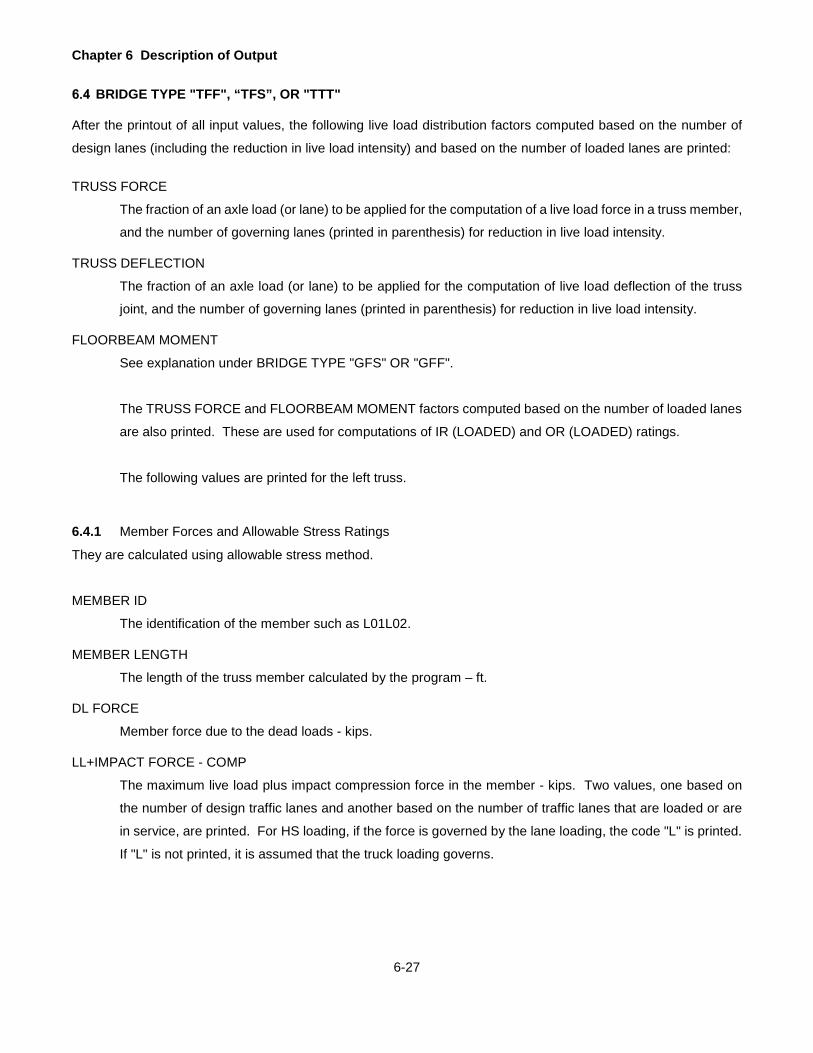
Chapter 6 Description of Output
6-27
BRIDGE TYPE "TFF", “TFS”, OR "TTT"
After the printout of all input values, the following live load distribution factors computed based on the number of
design lanes (including the reduction in live load intensity) and based on the number of loaded lanes are printed:
TRUSS FORCE
The fraction of an axle load (or lane) to be applied for the computation of a live load force in a truss member,
and the number of governing lanes (printed in parenthesis) for reduction in live load intensity.
TRUSS DEFLECTION
The fraction of an axle load (or lane) to be applied for the computation of live load deflection of the truss
joint, and the number of governing lanes (printed in parenthesis) for reduction in live load intensity.
FLOORBEAM MOMENT
See explanation under BRIDGE TYPE "GFS" OR "GFF".
The TRUSS FORCE and FLOORBEAM MOMENT factors computed based on the number of loaded lanes
are also printed. These are used for computations of IR (LOADED) and OR (LOADED) ratings.
The following values are printed for the left truss.
6.4.1 Member Forces and Allowable Stress Ratings
They are calculated using allowable stress method.
MEMBER ID
The identification of the member such as L01L02.
MEMBER LENGTH
The length of the truss member calculated by the program – ft.
DL FORCE
Member force due to the dead loads - kips.
LL+IMPACT FORCE - COMP
The maximum live load plus impact compression force in the member - kips. Two values, one based on
the number of design traffic lanes and another based on the number of traffic lanes that are loaded or are
in service, are printed. For HS loading, if the force is governed by the lane loading, the code "L" is printed.
If "L" is not printed, it is assumed that the truck loading governs.

Chapter 6 Description of Output
6-28
LL+IMPACT FORCE - TENS
The maximum live load plus impact tension force in the member - kips. Two values are printed. For HS
loading, if the force is governed by the lane loading, the code "L" is printed. If "L" is not printed, it is assumed
that the truck loading governs.
ALLOWABLE FORCE - COMP
The allowable compression force in the member - kips. The values for the IR, OR and SLC are printed.
ALLOWABLE FORCE - TENS
The allowable tension force in the member - kips. The values for the IR, OR and SLC are printed.
RATING FACTORS
Self-explanatory.
NOTE: If a given live loading does not produce any force in a truss member, IR (DESIGN) is printed as 999.99.
The dead load force and the allowable member forces are printed for reference only. Theoretically, this member
has an infinite rating for the given loading.
6.4.2 Member Strength and Load Factor Ratings
They are calculated using load factor method.
MEMBER ID
The identification of the member such as L01L02.
MEMBER LENGTH
The length of the truss member calculated by the program – ft.
DL FORCE
Member force due to the dead loads - kips.
LL+IMPACT FORCE - COMP
The maximum live load plus impact compression force in the member - kips. Two values, one based on
the number of design traffic lanes and another based on the number of traffic lanes that are loaded or are
in service, are printed. For HS loading, if the force is governed by the lane loading, the code "L" is printed.
If "L" is not printed, it is assumed that the truck loading governs.
LL+IMPACT FORCE - TENS
The maximum live load plus impact tension force in the member - kips. Two values are printed. For HS
loading, if the force is governed by the lane loading, the code "L" is printed. If "L" is not printed, it is assumed
that the truck loading governs.
AXIAL CAPACITY - COMP
The axial compression capacity in the member - kips. The values for the IR, OR and SLC are printed.
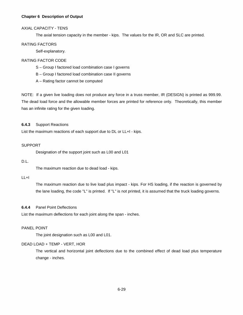
Chapter 6 Description of Output
6-29
AXIAL CAPACITY - TENS
The axial tension capacity in the member - kips. The values for the IR, OR and SLC are printed.
RATING FACTORS
Self-explanatory.
RATING FACTOR CODE
S – Group I factored load combination case I governs
B – Group I factored load combination case II governs
A – Rating factor cannot be computed
NOTE: If a given live loading does not produce any force in a truss member, IR (DESIGN) is printed as 999.99.
The dead load force and the allowable member forces are printed for reference only. Theoretically, this member
has an infinite rating for the given loading.
6.4.3 Support Reactions
List the maximum reactions of each support due to DL or LL+I - kips.
SUPPORT
Designation of the support joint such as L00 and L01
D.L.
The maximum reaction due to dead load - kips.
LL+I
The maximum reaction due to live load plus impact - kips. For HS loading, if the reaction is governed by
the lane loading, the code "L" is printed. If "L" is not printed, it is assumed that the truck loading governs.
6.4.4 Panel Point Deflections
List the maximum deflections for each joint along the span - inches.
PANEL POINT
The joint designation such as L00 and L01.
DEAD LOAD + TEMP - VERT, HOR
The vertical and horizontal joint deflections due to the combined effect of dead load plus temperature
change - inches.
Chapter 6 Description of Output
6-30
LIVE LOAD + IMPACT
The maximum deflections due to the live load plus impact - inches. For HS loading, if the deflection is
governed by the lane loading, the code "L" is printed. If "L" is not printed, it is assumed that the truck loading
governs.
VERT +
The maximum downward deflection - inches.
VERT -
The maximum upward deflection - inches.
HOR +
The maximum horizontal deflection to the right - inches.
HOR -
The maximum horizontal deflection to the left - inches.
6.4.5 Influence Line
If the output option is specified as 9, the following values are also printed.
REACTION INFLUENCE LINE FOR SUPPORT XXX
FORCE INFLUENCE LINE FOR MEMBER XXXXXX
INFLUENCE LINE FOR VERTICAL DEFLECTION AT XXX
INFLUENCE LINE FOR HORIZONTAL DEFLECTION AT XXX
The influence line ordinates for a given effect, where XXX represents a panel point and XXXXXX represents
the identification of the member. The values printed are the influence line ordinate followed by a joint
number in parenthesis. The ordinate represents the effect of a unit load applied at the joint.
POS AREA, NEG AREA etc.
For a truss without counters, each influence line is analyzed to find the maximum effect of a given live load.
The results of this analysis are printed here. These items are explained under the output option 9 for the
bridge type "GGG".
For a truss with counters, these values are not printed.
For the bridge type "TFS", the computed values for the stringer and floorbeam are printed in the same way
as explained for the bridge type "GFS".
For the bridge type "TFF", only the values for the floorbeam are printed.

Chapter 6 Description of Output
6-31
6.4.6 Fatigue Life Estimation
FATIGUE LIFE ESTIMATION
The following values are printed if the fatigue life analysis is requested for the truss.
LIVE LOAD DISTRIBUTION
The live load distribution factor (fraction of axle loads) for loading one lane that is used for calculating the
stress range.
PA TRAFFIC FACTOR
The Pennsylvania Traffic Factor (PTF) that is used in calculating the effective stress range for the fatigue
life equation. This value is 1.0 for ADTT less than or equal to 2500 (Case II or III Highways) and it is equal
to 1.1 for ADTT greater than 2500 (Case I Highways).
ALPHA FACTOR
The alpha factor that is used in calculating the effective stress range for the fatigue life equation. This is
equal to 0.5 since the program uses the conventional method of structural analysis.
GAMMA FACTOR
The gamma factor that is used in calculating the effective stress range for the fatigue life equation. This is
equal to 0.7 times the Pennsylvania Traffic Factor (PTF) if the Gross Vehicle Weight Distribution data are
not entered. This is the calculated value as per DM4 if the Gross Vehicle Weight Distribution data are
entered.
PAST GROWTH FACTOR or PAST CONSTANT ADTT
The growth factor for past ADTT in percent or the constant ADTT for the past.
FUTURE GROWTH FACTOR or FUTURE CONSTANT ADTT
The growth factor for future ADTT in percent or the constant ADTT for the future.
MEMBER
The identification of the member.
DL + HS20 TRUCK FORCE - MAXIMUM
The maximum axial force in the member due to dead loads and live load plus impact for an HS20 truck
loading. This value is based on the distribution factor for loading one lane - kips.
DL + HS20 TRUCK FORCE - MINIMUM
The minimum axial force in the member due to dead loads and live load plus impact for an HS20 truck
loading. This value is based on the distribution factor for loading one lane - kips.
CATEGORY
The stress category of detail as entered.

Chapter 6 Description of Output
6-32
STRESS RANGE – FSRD
The design fatigue stress range calculated using the live load distribution factor for one lane - ksi. The
value printed here is an algebraic difference of the maximum and the minimum stresses due to dead loads
and live load plus impact at this detail due to an HS20 truck placed in one lane. If the detail never
experiences a tensile stress, i.e. if the maximum and minimum stresses at this detail are compressive, the
fatigue stress range is assumed to be zero.
STRESS RANGE – FSR
The allowable fatigue stress range for cycles greater than 2,000,000 for the above category of detail - ksi.
STRESS RANGE – FSRE
The effective fatigue stress range as defined in DM4 - ksi. This value is equal to the design fatigue stress
range due to an HS20 truck in one lane multiplied by PA TRAFFIC FACTOR, ALPHA FACTOR and GAMMA
FACTOR printed above. If FSRD is zero or is less than FSR, this is printed as zero indicating that the detail
has infinite fatigue life.
DES FATIGUE LIFE CYCLES
The fatigue life in terms of cumulative truck cycles (number of times a design truck may pass over the
bridge). If FSR is greater than FSRD or if FSRD is zero, this is printed as 9999999999 signifying that the
detail has infinite fatigue life.
REMAIN YEARS
The remaining fatigue life of the detail - years.
The identification of critical member, estimated ADTT for the year the bridge was built, design fatigue life of the
critical member, accumulated cycles and estimated remaining life of the truss are printed next.
6.4.7 Pony Truss Stability Check
6.4.7.1 Lookup Table
This is the reprint of Table 7.1.2-1: Values of 1/K (1.000 to 0.085 for 30 values) for various values of CL/Pc
and N (4 to 16) with missing data linearly interpolated.
6.4.7.2 At Floorbeam Location
First Part:
1. TRUSS HEIGHT, h: The height of truss at the specified floorbeam support measured from the top of
the vertical chord to the half of the floorbeam depth – inches. 2. VERT MEMBER, Ic – the moment of inertia of the vertical member bending toward the midspan of the
floorbeam – in^4 3. FB SPAN, b – the floorbeam span between two supports – inches.
Chapter 6 Description of Output
6-33
4. FLOORBEAM, Ib – the moment of inertia of the floorbeam bending in positive flexure - inch^4 5. SPRING CONSTANT, c – Transverse Frame Spring Constant – kips/in 6. Pc – “2.00(CAP)” was printed here
Second Part:
1. MEMBER – MEMBER ID such as L01U01 2. ** - Legend of member types: T for top chord, E for end post, and V for vertical chord. 3. CHORD, Lu – unsupported length of the truss member - inches 4. MEMBER CAPACITY – the factor of safety (2.0) * the original LFD member capacity computed using
the BAR7-default K values depending on the pinned or riveted end connection selected from the user
– kips. 5. CL/Pc – the value of (SPRING CONSTANT*CHORD/MEMBER CAPACITY). 6. COMPUTED 1/K VALUE – the value obtained from the lookup table 7. COMPUTED PONY-K VALUE – the value of 1/(COMPUTED 1/K VALUE) 8. BAR7 DEFAULT-K VALUE – for pinned connection, it is 0.875 and for riveted connection, it is 0.75. 9. CONTROLLING K VALUE – the largest value between COMPUTED PONY-K VALUE and BAR7
DEFAULT-K VALUE 10. FACTORED CHORD VALUE, K*Lu – the value of CONTROLLING K VALUES*Lu - inches
6.4.7.3 Final K Values Used in the Analysis and Rating
1. MEMBER – Member ID such as L01U01 2. CHORD, Lu – Unsupported length of the truss member - inches 3. CONTROLLING K VALUES: For each member, select the largest K values from each joint analyzed if
multiple values exist. 4. FACTORED CHORD VALUE, K*Lu - the value of CONTROLLING K VALUES *Lu- inches
Chapter 6 Description of Output
6-34
GUSSET PLATE ANALYSIS AND OPERATING RATINGS
The LFD gusset plate analysis and ratings consist of the dead and live load analysis results (forces and moments
for gusset plate sections and connected members) as well as the capacity and operating level ratings of the gusset
plate and connected members. The program outputs appropriate live loads defined by the user. These different live
loads are indicated in each of the headings as "LL = …"
6.5.1 DL & LL Forces and Angles - Part 1, 2, and 3 of 3 (LL = …)
This output record contains the unfactored dead loads, unfactored live loads, and angles for each gusset
plate member ii.
1. Plate Location - the gusset plate designation, denoted by the joint of the truss.
2. Member ID - the specific truss member that corresponds to each gusset plate member ii.
3. Dead Load Forces, DC - the dead load (DC) axial force applied to member ii.
4. Dead Load Forces, DW - the dead load (DW) axial force applied to member ii.
5. Live Load Forces, Tension - the live load tensile force applied to member ii.
6. Live Load Forces, Compression - the live load compressive force applied to member ii.
7. Angle Theta - angles measured from a vertical line at the centerline of the gusset to the line of
action of the member.
6.5.2 Shear At Section A-A: LL Match DL (LL = …)
This output record contains section properties, factored effects, operating capacity and operating level
rating factor for each gusset plate. Live loads from each member have the same sign as the dead loads in
each member. Section A-A is shown in Figure 5.22.1 on page 5-97 to Figure 5.22.4 on page 5-100.
1. Plate Location - the gusset plate designation, denoted by the joint of the truss.
2. Section Properties, Ag - the gross cross-sectional area of one gusset plate along the Section A-A, = Ha*t.
3. Section Properties, An - the net cross-sectional area of one gusset plate along the Section A-A, = Ag - (number of holes)*(hole diamters)*t.
4. Section Properties, S - the section modulus of one gusset plate with respect to section A-A, = (Ha*Ha*t)/6
5. Equilibrating Forces, Axial - the maximum factored axial force, tension or compression. These equilibrating axial forces were computed from the free body diagram along the section A-A..
6. Equilibrating Forces, Shear - the maximum factored shear force. These equilibrating shear forces were computed from the free body diagram along the section A-A..
7. Equilibrating Forces, Moment - the maximum factored moment. These equilibrating moments were computed from the free body diagram along the section A-A.
Chapter 6 Description of Output
6-35
8. Nominal Capacity, Minimum - the nominal shear capacity at operating level, a minimum between Pvg
and Pvn, the gross area shear capacity at operating level and the net area shear capacity.
9. Nominal Capacity, Governing - the governing area, gross or net (denoted by "g" or "n") from which
the nominal shear capacity is calculated.
10. Capacity Check - a check indicating if the nominal capacity is greater than the factored shear force.
NOTE: For truss spans over 500 feet long, LFD loads used for the supplementary check of capacity
have been factored per Group I in accordance with the Guide Spec. Article 1.2.
11. Operating Level Rating - the rating factor for shear force based upon the nominal capacity, dead load,
and live load results. If the rating factor cannot be calculated because the live load force is equal to
0.0, +++ will print in this column.
6.5.3 Shear At Section A-A: LL Compressive (LL = …)
The same information is printed on this table as described in Section 6.5.2, except that the calculations
reported on this table utilize the compressive live load member force instead of the matching live load
member force. Section A-A is shown in Figure 5.22.1 on page 5-97 to Figure 5.22.4 on page 5-100.
6.5.4 Shear At Section A-A: LL Tensile (LL = …)
The same information is printed on this table as described in Section 6.5.2, except that the calculations
reported on this table utilize the tensile live load member force instead of the matching live load member
force. Section A-A is shown in Figure 5.22.1 on page 5-97 to Figure 5.22.4 on page 5-100.
6.5.5 Shear At Section B-B: LL Match DL (LL = …)
The same information is printed on this table as described in Section 6.5.2, except that the calculations
reported on this table come from section B-B. Section B-B is shown in Figure 5.22.1 on page 5-97 to Figure
5.22.4 on page 5-100.
6.5.6 Shear At Section B-B: LL Compressive (LL = …)
The same information is printed on this table as described in Section 6.5.3, except that the calculations
reported on this table come from section B-B. Section B-B is shown in Figure 5.22.1 on page 5-97 to Figure
5.22.4 on page 5-100.
6.5.7 Shear At Section B-B: LL Tensile (LL = …)
The same information is printed on this table as described in Section 6.5.4, except that the calculations
reported on this table come from section B-B. Section B-B is shown in Figure 5.22.1 on page 5-97 to Figure
5.22.4 on page 5-100.
Chapter 6 Description of Output
6-36
6.5.8 Shear At Section C-C: LL Match DL (LL = …)
The same information is printed on this table as described in Section 6.5.2, except that the calculations
reported on this table come from section C-C. Section C-C is shown in Figure 5.22.1 on page 5-97 to Figure
5.22.4 on page 5-100.
6.5.9 Shear At Section C-C: LL Compressive (LL = …)
The same information is printed on this table as described in Section 6.5.3, except that the calculations
reported on this table come from section C-C. Section C-C is shown in Figure 5.22.1 on page 5-97 to Figure
5.22.4 on page 5-100.
6.5.10 Shear At Section C-C: LL Tensile (LL = …)
The same information is printed on this table as described in Section 6.5.4, except that the calculations
reported on this table come from section C-C. Section C-C is shown in Figure 5.22.1 on page 5-97 to Figure
5.22.4 on page 5-100.
6.5.11 Tension and Compression: LL Match DL (LL = …)
This output record contains the factored effects for each member, up to five members, connected to the
gusset plate, the capacity of gusset plate at each member and the operating level rating factor resulting
from these loads. Live loads from each member have the same sign as the dead loads in each member.
1. Plate Location - the gusset plate designation, denoted by the joint of the truss.
2. Member - the gusset plate member designation, as specified in Figure 5.22.1 on page 5-97 to Figure
5.22.4 on page 5-100.
3. Axial Force - the maximum factored axial force acting upon the end of the specified member.
4. Operating Level Capacity, Minimum - the nominal axial capacity of gusset plate at each member,
either tension or compression.
5. Operating Level Capacity, Governing - the governing area. If the governing nominal capacity is
tensile, the governing area will be either gross or net area (denoted by "Tg" or "Tn") respectively. If
the governing nominal capacity is compressive, the governing area will be denoted by "C".
6. Capacity Check - a check indicating that the nominal capacity is greater than the factored axial force.
NOTE: For truss spans over 500 feet long, LFD loads used for the supplementary check of capacity
have been factored per Group I in accordance with the Guide Spec. Article 1.2.
7. Operating Level, Rating - the rating factor for tension and compression of gusset plate at each
member ends based upon the nominal capacity, dead load, and live load results. If the rating factor
cannot be calculated because the live load force is equal to 0.0, +++ will print in this column.
8. Operating Level, Governing - the governing axial force condition by which the rating was computed,
either tension or compression ("T" or "C").
Chapter 6 Description of Output
6-37
6.5.12 Tension and Compression: LL Compressive (LL = …)
The same information is printed on this table as described in Section 6.5.11, except that the calculations
reported on this table utilize the compressive live load force instead of the matching live load force.
6.5.13 Tension and Compression: LL Tensile (LL = …)
The same information is printed on this table as described in Section 6.5.11, except that the calculations
reported on this table utilize the tensile live load force instead of the matching live load force.
6.5.14 Block Shear: LL Match DL (LL = …)
This output record contains the factored effects for each member, up to five members, connected to the
gusset plate, the capacity of gusset plate at each member and the resulting operating level rating factor. In
addition, the combination of a vertical and diagonal member (referred to as "VRT-DGL" in the output record)
and its corresponding effect and operating level rating factor is also computed by the program. Live loads
from each member have the same sign as the dead loads in each member.
1. Plate Location - the gusset plate designation, denoted by the joint of the truss.
2. Member - the gusset plate member designation, as specified in Figure 5.22.1 on page 5-97 to Figure
5.22.4 on page 5-100.
3. Block Shear Force - the maximum factored block shear force acting upon the end of the specified
gusset plate member, either tensile (T) or compressive (C).
4. Operating Level Capacity, Pbs - the nominal block shear capacity.
5. Operating Level Capacity, Governing - the governing block shear case. For members 1 and 2, block
shear case 1 ("B1") or 2 ("B2"). For members 3-5, case 2 ("B2"). For the vertical-diagonal member,
block shear case 3 ("B3"). See Figure 3.11.2 on page 3-77.
6. Capacity Check - a check indicating that the nominal capacity is greater than the factored block shear
force. NOTE: For truss spans over 500 feet long, LFD loads used for the supplementary check of
capacity have been factored per Group I in accordance with the Guide Spec. Article 1.2.
7. Operating Level Rating - the rating factor for block shear based upon the operating level capacity,
dead load, and live load results. If the rating factor cannot be calculated because the live load force
is equal to 0.0, +++ will print in this column.
6.5.15 Block Shear: LL Compressive (LL = …)
The same information is printed on this table as described in Section 6.5.14, except that the calculations
reported on this table utilize the compressive live load force instead of the matching live load force.
Chapter 6 Description of Output
6-38
6.5.16 Block Shear: LL Tensile (LL = …)
The same information is printed on this table as described in Section 6.5.14, except that the calculations
reported on this table utilize the tensile live load force instead of the matching live load force.
6.5.17 Connections: LL Match DL (LL = …)
This output record contains the factored effects for each member, up to five members, connected to the
gusset plate, the connection capacity at each member and the operating level rating factor resulting from
these loads. Live loads from each member have the same sign as the dead loads in each member.
1. Plate Location - the gusset plate designation, denoted by the joint of the truss.
2. Member - the gusset plate member designation, as specified in Figure 5.22.1 on page 5-97 to Figure
5.22.4 on page 5-100.
3. Axial Force - the maximum factored axial force applied to the gusset plate member.
4. Operating Level Capacity, Minimum (Rv, Rb) - the nominal connection capacity, a minimum between
Rv (the shear capacity of all bolts or rivets) and Rb (the capacity of the connection in bearing).
5. Operating Level Capacity, Governing - the governing connection type, fastener shear ("FS") or
bearing on material ("MB"), by which the nominal capacity was computed.
6. Capacity Check - a check indicating that the nominal capacity is greater than the factored axial force.
NOTE: For truss spans over 500 feet long, LFD loads used for the supplementary check of capacity
have been factored per Group I in accordance with the Guide Spec. Article 1.2.
7. Operating Level, Rating - the rating factor for the gusset plate connection based upon the Operating
Level capacity, dead load, and live load results. If the rating factor cannot be calculated because the
live load force is equal to 0.0, +++ will print in this column.
8. Operating Level, Governing - the governing operating level rating type, fastener shear ("FS") or
bearing on material ("MB"), by which the rating was computed.
6.5.18 Connections: LL Compressive (LL = …)
The same information is printed on this table as described in Section 6.5.17, except that the calculations
reported on this table utilize the compressive live load force instead of the matching live load force.
6.5.19 Connections: LL Tensile (LL = …)
The same information is printed on this table as described in Section 6.5.17, except that the calculations
reported on this table utilize the tensile live load force instead of the matching live load force.

Chapter 6 Description of Output
6-39
6.5.20 Summary Part 1 of 3: LL Match DL (LL = …)
This output record contains the governing factored effects, capacity and operating level rating for each
gusset plate for shear and tension. Live loads have the same sign as the dead loads when factoring the
forces.
1. Plate Location - the gusset plate location designation, denoted by the joint of the truss.
2. Shear, Shear Force - the maximum factored shear force at Section A-A, Section B-B, or Section C-
C, denoted by "A", "B", or "C" respectively. Sections A-A, B-B and C-C are shown in Figure 5.22.1
on page 5-97 to Figure 5.22.4 on page 5-100.
3. Shear, Operating Level Capacity - the operating level shear capacity, a minimum between Pvg and
Pvn, the gross area shear force capacity and net area shear force capacity, indicated by "g" or "n"
respectively.
4. Shear, Capacity Check - a check indicating if the nominal capacity is greater than the shear force.
NOTE: For truss spans over 500 feet long, LFD loads used for the supplementary check of capacity
have been factored per Group I in accordance with the Guide Spec. Article 1.2.
5. Shear, Operating Level Rating - the rating factor for shear (at Section A-A, Section B-B, or Section
C-C denoted by "A", "B", or "C" respectively) based upon the nominal capacity, dead load, and live
load results. Sections A-A, B-B and C-C are shown in Figure 5.22.1 on page 5-97 to Figure 5.22.5
on page 5-101. If the rating factor cannot be calculated because the live load force is equal to 0.0,
+++ will print in this column.
6. Tension, Axial Load - the maximum factored tensile axial force acting upon the end of the gusset
plate member, denoted by M.1, M.2, M.3, M.4, M.5 for members 1 through 5, as specified in Figure
5.22.1 on page 5-97 to Figure 5.22.4 on page 5-100.
7. Tension, Operating Level Capacity - the operating level axial tensile capacity of the gusset plate
member, denoted by M.1, M.2, M.3, M.4, M.5 for members 1 through 5, as specified in Figure 5.22.1
on page 5-97 to Figure 5.22.4 on page 5-100.
8. Tension, Capacity Check - a check indicating that the nominal capacity is greater than the factored
axial force. NOTE: For truss spans over 500 feet long, LFD loads used for the supplementary check
of capacity have been factored per Group I in accordance with the Guide Spec. Article 1.2.
9. Tension, Operating Level Rating – the rating factor for tension of member ends (denoted by M.1, M.2,
M.3, M.4, and M.5 for members 1 through 5, as specified in Figure 5.22.1 on page 5-97 to Figure
5.22.4 on page 5-100) based upon the nominal capacity, dead load, and live load results. If the rating
factor cannot be calculated because the live load force is equal to 0.0, +++ will print in this column.
6.5.21 Summary Part 1 of 3: LL Compressive (LL = …)
The same information is printed on this table as described in Section 6.5.20, except that the calculations
reported on this table utilize the compressive live load force instead of the matching live load force.

Chapter 6 Description of Output
6-40
6.5.22 Summary Part 1 of 3: LL Tensile (LL = …)
The same information is printed on this table as described in Section 6.5.20, except that the calculations
reported on this table utilize the tensile live load force instead of the matching live load force.
6.5.23 Summary Part 2 of 3: LL Match DL (LL = …)
This output record contains the governing factored effects, capacity and operating level rating for each
gusset plate for compression and block shear. Live loads have the same sign as the dead loads when
factoring the axial forces.
1. Plate Location - the gusset plate location designation, denoted by the joint of the truss.
2. Compression, Axial Load - the maximum compressive factored axial force acting upon the end of the
gusset plate member, denoted by M.1, M.2, M.3, M.4, M.5 for members 1 through 5, as specified in
Figure 5.22.1 on page 5-97 to Figure 5.22.4 on page 5-100.
3. Compression, Operating Level Capacity - the operating level axial compressive capacity of the gusset
plate member, denoted by M.1, M.2, M.3, M.4, M.5 for members 1 through 5, as specified in Figure
5.22.1 on page 5-97 to Figure 5.22.4 on page 5-100.
4. Compression, Capacity Check - a check indicating if the nominal capacity is greater than the factored
axial force. NOTE: For truss spans over 500 feet long, LFD loads used for the supplementary check
of capacity have been factored per Group I in accordance with the Guide Spec. Article 1.2.
5. Compression, Operating Level Rating – the rating factor for compression of member ends (denoted
by M.1, M.2, M.3, M.4, and M.5 for members 1 through 5 as specified in Figure 5.22.1 on page 5-97
to Figure 5.22.4 on page 5-100) based upon the nominal capacity, dead load, and live load results.
If the rating factor cannot be calculated because the live load force is equal to 0.0, +++ will print in
this column.
6. Block Shear, Block Shear Force - the maximum factored block shear force acting upon the end of
the gusset plate member, denoted by M.1, M.2, M.3, M.4, M.5 for members 1 through 5, as specified
in Figure 5.22.1 on page 5-97 to Figure 5.22.4 on page 5-100, or B.3 for block shear case 3.
7. Block Shear, Operating Level Capacity - the operating level block shear capacity of the gusset plate
member, denoted by M.1, M.2, M.3, M.4, M.5 for members 1 through 5, as specified in Figure 5.22.1
on page 5-97 to Figure 5.22.4 on page 5-100, or B.3 for block shear case 3.
8. Block Shear, Capacity Check - a check indicating if the nominal capacity is greater than the factored
block shear force. NOTE: For truss spans over 500 feet long, LFD loads used for the supplementary
check of capacity have been factored per Group I in accordance with the Guide Spec. Article 1.2.
9. Block Shear, Operating Level Rating - the rating factor for block shear (denoted by M.1, M.2, M.3,
M.4, and M.5 for members 1 through 5 as specified in Figure 5.22.1 on page 5-97 to Figure 5.22.5
on page 5-101) or B.3 for block shear case 3) based upon the nominal capacity, dead load, and live
load results. If the rating factor cannot be calculated because the live load force is equal to 0.0, +++
will print in this column.
Chapter 6 Description of Output
6-41
6.5.24 Summary Part 2 of 3: LL Compressive (LL = …)
The same information is printed on this table as described in Section 6.5.23, except that the calculations
reported on this table utilize the compressive live load force instead of the matching live load force.
6.5.25 Summary Part 2 of 3: LL Tensile (LL = …)
The same information is printed on this table as described in Section 6.5.23, except that the calculations
reported on this table utilize the tensile live load force instead of the matching live load force.
6.5.26 Summary Part 3 of 3: LL Match DL (LL = …)
This output record contains the governing factored effects, capacity and operating level rating for each
gusset plate for connections, as well as the overall critical operating rating for each gusset plate. Live loads
have the same sign as the dead loads when factoring the axial forces.
1. Plate Location - the gusset plate location designation, denoted by the joint of the truss.
2. Connections, Axial Load - the maximum factored axial force acting on the connection of the gusset
plate member, denoted by M.1, M.2, M.3, M.4, M.5 for members 1 through 5, as specified in Figure
5.22.1 on page 5-97 to Figure 5.22.4 on page 5-100.
3. Connections, Operating Level Capacity - the operating level connection capacity of the gusset plate
member, denoted by M.1, M.2, M.3, M.4, M.5 for members 1 through 5, as specified in Figure 5.22.1
on page 5-97 to Figure 5.22.4 on page 5-100.
4. Connections, Capacity Check - a check indicating if the operating level capacity is greater than the
factored axial force. NOTE: For truss spans over 500 feet long, LFD loads used for the supplementary
check of capacity have been factored per Group I in accordance with the Guide Spec. Article 1.2.
5. Connections, Operating Level Rating - the minimum rating factor for the connections (denoted by
M.1, M.2, M.3, M.4, M.5 for members 1 through 5, as specified in Figure 5.22.1 on page 5-97 to
Figure 5.22.4 on page 5-100) based upon the nominal capacity, dead load, and live load results. If
the rating factor cannot be calculated because the live load force is equal to 0.0, +++ will print in this
column.
6.5.27 Summary Part 3 of 3: LL Compressive (LL = …)
The same information is printed on this table as described in Section 6.5.26, except that the calculations
reported on this table utilize the compressive live load force instead of the matching live load force.
6.5.28 Summary Part 3 of 3: LL Tensile (LL = …)
The same information is printed on this table as described in Section 6.5.26, except that the calculations
reported on this table utilize the tensile live load force instead of the matching live load force.

Chapter 6 Description of Output
6-42
6.5.29 Governing Operating Ratings: All Cases, LL = …
This output record contains the governing operating rating for each gusset plate and the live load condition
that produces it. The record also contains the unsupported edge in compression adequacy check for each
plate.
1. Plate Location - the gusset plate location designation, denoted by the joint of the truss.
2. Unsupported Edge In Compression Adequacy Check - a check indicating that the unsupported edges
in compression do not require stiffening.
3. Minimum Operating Ratings, LL Match DL - the minimum operating rating for the case where the sign
of the live load matches the sign of the dead load. The check resulting in the rating is denoted by "Blks"
for the block shear check, "Comp" for the compression check, "Conn" for the connection check, "Shea"
for the shear check or "Tens" for the tension check.
4. Minimum Operating Ratings, LL Compressive - same as parameter 3, except that the live load for this
case is always compressive.
5. Minimum Operating Ratings, LL Tensile - same as parameter 3, except that the live load for this case
is always tensile.
6. Minimum Operating Ratings, Overall - the final governing operating rating for the gusset plate; the
minimum of parameters 4, 5, and 6.
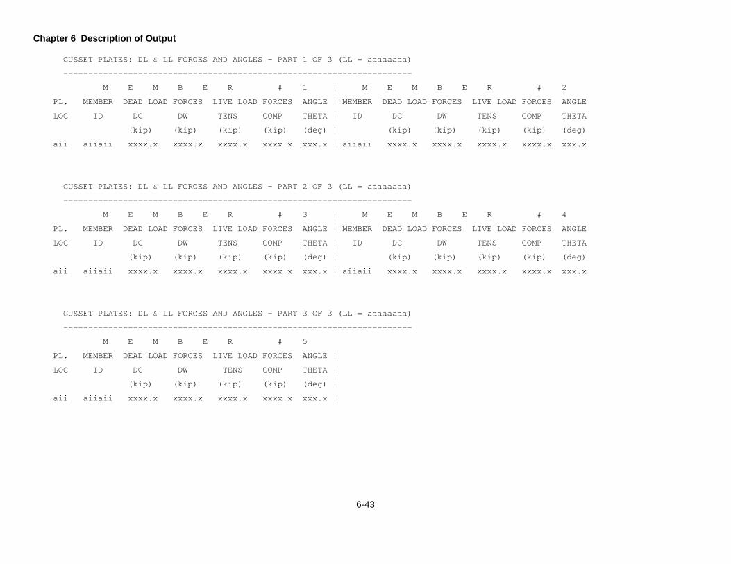
Chapter 6 Description of Output
6-43
GUSSET PLATES: DL & LL FORCES AND ANGLES - PART 1 OF 3 (LL = aaaaaaaa)
----------------------------------------------------------------------
M E M B E R # 1 | M E M B E R # 2
PL. MEMBER DEAD LOAD FORCES LIVE LOAD FORCES ANGLE | MEMBER DEAD LOAD FORCES LIVE LOAD FORCES ANGLE
LOC ID DC DW TENS COMP THETA | ID DC DW TENS COMP THETA
(kip) (kip) (kip) (kip) (deg) | (kip) (kip) (kip) (kip) (deg)
aii aiiaii xxxx.x xxxx.x xxxx.x xxxx.x xxx.x | aiiaii xxxx.x xxxx.x xxxx.x xxxx.x xxx.x
GUSSET PLATES: DL & LL FORCES AND ANGLES - PART 2 OF 3 (LL = aaaaaaaa)
----------------------------------------------------------------------
M E M B E R # 3 | M E M B E R # 4
PL. MEMBER DEAD LOAD FORCES LIVE LOAD FORCES ANGLE | MEMBER DEAD LOAD FORCES LIVE LOAD FORCES ANGLE
LOC ID DC DW TENS COMP THETA | ID DC DW TENS COMP THETA
(kip) (kip) (kip) (kip) (deg) | (kip) (kip) (kip) (kip) (deg)
aii aiiaii xxxx.x xxxx.x xxxx.x xxxx.x xxx.x | aiiaii xxxx.x xxxx.x xxxx.x xxxx.x xxx.x
GUSSET PLATES: DL & LL FORCES AND ANGLES - PART 3 OF 3 (LL = aaaaaaaa)
----------------------------------------------------------------------
M E M B E R # 5
PL. MEMBER DEAD LOAD FORCES LIVE LOAD FORCES ANGLE |
LOC ID DC DW TENS COMP THETA |
(kip) (kip) (kip) (kip) (deg) |
aii aiiaii xxxx.x xxxx.x xxxx.x xxxx.x xxx.x |
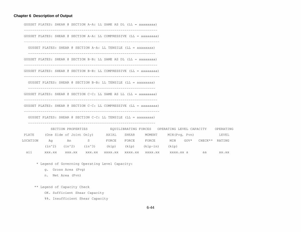
Chapter 6 Description of Output
6-44
GUSSET PLATES: SHEAR @ SECTION A-A: LL SAME AS DL (LL = aaaaaaaa)
-----------------------------------------------------------------
GUSSET PLATES: SHEAR @ SECTION A-A: LL COMPRESSIVE (LL = aaaaaaaa)
------------------------------------------------------------------
GUSSET PLATES: SHEAR @ SECTION A-A: LL TENSILE (LL = aaaaaaaa)
--------------------------------------------------------------
GUSSET PLATES: SHEAR @ SECTION B-B: LL SAME AS DL (LL = aaaaaaaa)
-----------------------------------------------------------------
GUSSET PLATES: SHEAR @ SECTION B-B: LL COMPRESSIVE (LL = aaaaaaaa)
------------------------------------------------------------------
GUSSET PLATES: SHEAR @ SECTION B-B: LL TENSILE (LL = aaaaaaaa)
--------------------------------------------------------------
GUSSET PLATES: SHEAR @ SECTION C-C: LL SAME AS LL (LL = aaaaaaaa)
-----------------------------------------------------------------
GUSSET PLATES: SHEAR @ SECTION C-C: LL COMPRESSIVE (LL = aaaaaaaa)
------------------------------------------------------------------
GUSSET PLATES: SHEAR @ SECTION C-C: LL TENSILE (LL = aaaaaaaa)
--------------------------------------------------------------
SECTION PROPERTIES EQUILIBRATING FORCES OPERATING LEVEL CAPACITY OPERATING
PLATE (One Side of Joint Only) AXIAL SHEAR MOMENT MIN(Pvg, Pvn) LEVEL
LOCATION Ag An S FORCE FORCE FORCE MIN GOV* CHECK** RATING
(in^2) (in^2) (in^3) (kip) (kip) (kip-in) (kip)
aii xxx.xx xxx.xx xxx.xx xxxx.xx xxxx.xx xxxx.xx xxxx.xx a aa xx.xx
* Legend of Governing Operating Level Capacity:
g. Gross Area (Pvg)
n. Net Area (Pvn)
** Legend of Capacity Check
OK. Sufficient Shear Capacity
%%. Insufficient Shear Capacity

Chapter 6 Description of Output
6-45
NOTE: For truss spans over 500 feet long, LFD loads used for the
supplementary check of capacity have been factored
per Group I in accordance with the Guide Spec. Article 1.2.
+++ Rating factor not calculated because live load effect = 0.0
GUSSET PLATES: TENSION & COMPRESSION: LL SAME AS DL (LL = aaaaaaaa)
-------------------------------------------------------------------
GUSSET PLATES: TENSION & COMPRESSION: LL COMPRESSIVE (LL = aaaaaaaa)
--------------------------------------------------------------------
GUSSET PLATES: TENSION & COMPRESSION: LL TENSILE (LL = aaaaaaaa)
----------------------------------------------------------------
FACTORED OPERATING LEVEL CAPACITY OPERATING
PLATE AXIAL MIN (Pt, Pc) LEVEL
LOCATION MEMBER FORCE* MIN GOV** CHECK*** RATING GOV*
(kip) (kip)
aii 1 xxxx.xx a xxxx.xx aa aa xx.xx a
2 xxxx.xx a xxxx.xx aa aa xx.xx a
3 xxxx.xx a xxxx.xx aa aa xx.xx a
4 xxxx.xx a xxxx.xx aa aa xx.xx a
5 xxxx.xx a xxxx.xx aa aa xx.xx a
* Legend of Governing Factored Axial Force:
C. Compression
T. Tension
** Legend of Governing Operating Level Capacity:
C. Compression, (Pc)
Tg. Tension, Gross Area (Pt)
Tn. Tension, Net Area (Pt)
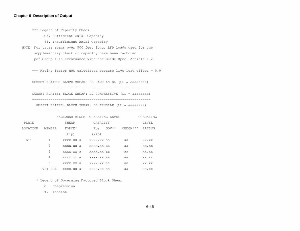
Chapter 6 Description of Output
6-46
*** Legend of Capacity Check
OK. Sufficient Axial Capacity
%%. Insufficient Axial Capacity
NOTE: For truss spans over 500 feet long, LFD loads used for the
supplementary check of capacity have been factored
per Group I in accordance with the Guide Spec. Article 1.2.
+++ Rating factor not calculated because live load effect = 0.0
GUSSET PLATES: BLOCK SHEAR: LL SAME AS DL (LL = aaaaaaaa)
---------------------------------------------------------
GUSSET PLATES: BLOCK SHEAR: LL COMPRESSIVE (LL = aaaaaaaa)
----------------------------------------------------------
GUSSET PLATES: BLOCK SHEAR: LL TENSILE (LL = aaaaaaaa)
------------------------------------------------------
FACTORED BLOCK OPERATING LEVEL OPERATING
PLATE SHEAR CAPACITY LEVEL
LOCATION MEMBER FORCE* Pbs GOV** CHECK*** RATING
(kip) (kip)
aii 1 xxxx.xx a xxxx.xx aa aa xx.xx
2 xxxx.xx a xxxx.xx aa aa xx.xx
3 xxxx.xx a xxxx.xx aa aa xx.xx
4 xxxx.xx a xxxx.xx aa aa xx.xx
5 xxxx.xx a xxxx.xx aa aa xx.xx
VRT-DGL xxxx.xx a xxxx.xx aa aa xx.xx
* Legend of Governing Factored Block Shear:
C. Compression
T. Tension
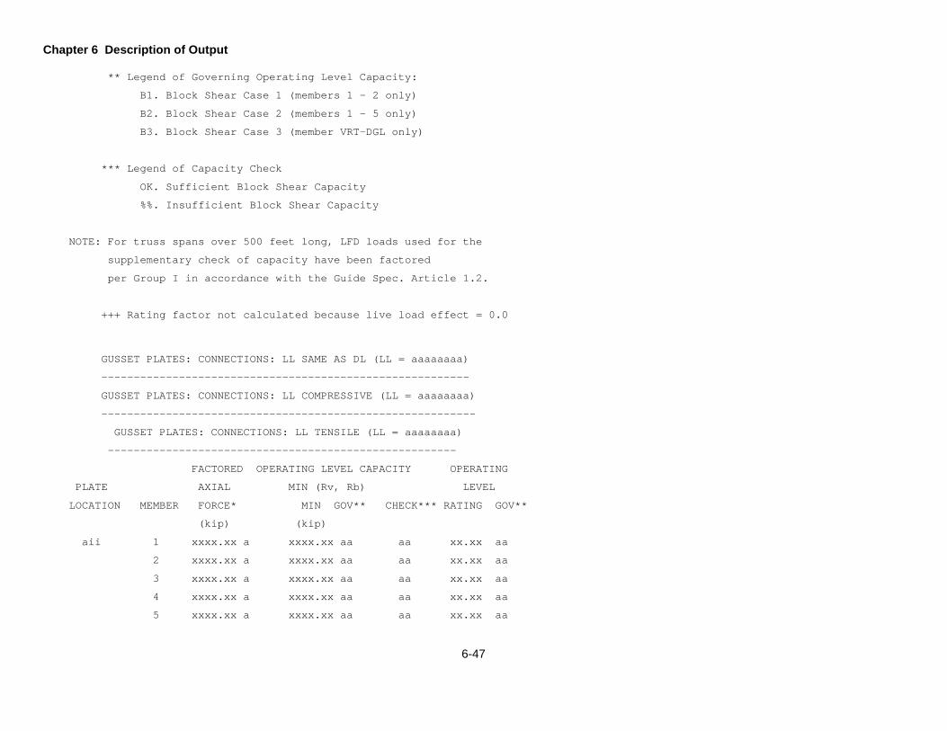
Chapter 6 Description of Output
6-47
** Legend of Governing Operating Level Capacity:
B1. Block Shear Case 1 (members 1 - 2 only)
B2. Block Shear Case 2 (members 1 - 5 only)
B3. Block Shear Case 3 (member VRT-DGL only)
*** Legend of Capacity Check
OK. Sufficient Block Shear Capacity
%%. Insufficient Block Shear Capacity
NOTE: For truss spans over 500 feet long, LFD loads used for the
supplementary check of capacity have been factored
per Group I in accordance with the Guide Spec. Article 1.2.
+++ Rating factor not calculated because live load effect = 0.0
GUSSET PLATES: CONNECTIONS: LL SAME AS DL (LL = aaaaaaaa)
---------------------------------------------------------
GUSSET PLATES: CONNECTIONS: LL COMPRESSIVE (LL = aaaaaaaa)
----------------------------------------------------------
GUSSET PLATES: CONNECTIONS: LL TENSILE (LL = aaaaaaaa)
------------------------------------------------------
FACTORED OPERATING LEVEL CAPACITY OPERATING
PLATE AXIAL MIN (Rv, Rb) LEVEL
LOCATION MEMBER FORCE* MIN GOV** CHECK*** RATING GOV**
(kip) (kip)
aii 1 xxxx.xx a xxxx.xx aa aa xx.xx aa
2 xxxx.xx a xxxx.xx aa aa xx.xx aa
3 xxxx.xx a xxxx.xx aa aa xx.xx aa
4 xxxx.xx a xxxx.xx aa aa xx.xx aa
5 xxxx.xx a xxxx.xx aa aa xx.xx aa

Chapter 6 Description of Output
6-48
* Legend of Governing factored Axial Force:
C. Compression
T. Tension
** Legend of Governing Operating Level Capacity:
FS. Fastener Shear (Rv)
MB. Bearing on Material (Rb)
*** Legend of Capacity Check
OK. Sufficient Connection Capacity
NG. Insufficient Connection Capacity
+++ Rating factor not calculated because live load effect = 0.0

Chapter 6 Description of Output
6-49
GUSSET PLATES: SUMMARY PART 1 OF 3: LL SAME AS DL (LL = aaaaaaaa)
-----------------------------------------------------------------
GUSSET PLATES: SUMMARY PART 1 OF 3: LL COMPRESSIVE (LL = aaaaaaaa)
------------------------------------------------------------------
GUSSET PLATES: SUMMARY PART 1 OF 3: LL TENSILE (LL = aaaaaaaa)
--------------------------------------------------------------
S H E A R T E N S I O N
OPERATING OPERATING
PLATE SHEAR OPERATING LEVEL LEVEL AXIAL OPERATING LEVEL LEVEL
LOCATION FORCE* CAPACITY* CHECK*** RATING* LOAD** CAPACITY** CHECK*** RATING**
(kip) (kip) (kip) (kip)
aii xxx.xx a xxx.xx a aa xx.xx a xxx.xx a.a xxx.xx a.a aa | xx.xx a.a
* Factored Shear Force, Operating Level Capacity, and Operating Level Rating:
A. Shear @ Section A-A
B. Shear @ Section B-B
C. Shear @ Section C-C
g. Gross Area
n. Net Area
** Legend of Factored Tension Axial Load, Operating Level Capacity, and Operating Level Rating:
M.1. Member 1
M.2. Member 2
M.3. Member 3
M.4. Member 4
M.5. Member 5
*** Legend of Capacity Check
OK. Sufficient Capacity
%%. Insufficient Capacity
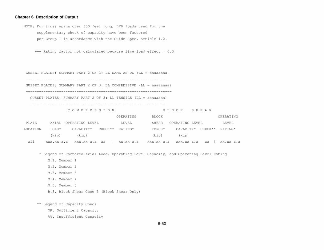
Chapter 6 Description of Output
6-50
NOTE: For truss spans over 500 feet long, LFD loads used for the
supplementary check of capacity have been factored
per Group I in accordance with the Guide Spec. Article 1.2.
+++ Rating factor not calculated because live load effect = 0.0
GUSSET PLATES: SUMMARY PART 2 OF 3: LL SAME AS DL (LL = aaaaaaaa)
-----------------------------------------------------------------
GUSSET PLATES: SUMMARY PART 2 OF 3: LL COMPRESSIVE (LL = aaaaaaaa)
------------------------------------------------------------------
GUSSET PLATES: SUMMARY PART 2 OF 3: LL TENSILE (LL = aaaaaaaa)
--------------------------------------------------------------
C O M P R E S S I O N B L O C K S H E A R
OPERATING BLOCK OPERATING
PLATE AXIAL OPERATING LEVEL LEVEL SHEAR OPERATING LEVEL LEVEL
LOCATION LOAD* CAPACITY* CHECK** RATING* FORCE* CAPACITY* CHECK** RATING*
(kip) (kip) (kip) (kip)
aii xxx.xx a.a xxx.xx a.a aa | xx.xx a.a xxx.xx a.a xxx.xx a.a aa | xx.xx a.a
* Legend of Factored Axial Load, Operating Level Capacity, and Operating Level Rating:
M.1. Member 1
M.2. Member 2
M.3. Member 3
M.4. Member 4
M.5. Member 5
B.3. Block Shear Case 3 (Block Shear Only)
** Legend of Capacity Check
OK. Sufficient Capacity
%%. Insufficient Capacity

Chapter 6 Description of Output
6-51
NOTE: For truss spans over 500 feet long, LFD loads used for the
supplementary check of capacity have been factored
per Group I in accordance with the Guide Spec. Article 1.2.
+++ Rating factor not calculated because live load effect = 0.0
GUSSET PLATES: SUMMARY PART 3 OF 3: LL SAME AS DL (LL = aaaaaaaa)
-----------------------------------------------------------------
GUSSET PLATES: SUMMARY PART 3 OF 3: LL COMPRESSIVE (LL = aaaaaaaa)
------------------------------------------------------------------
GUSSET PLATES: SUMMARY PART 3 OF 3: LL TENSILE (LL = aaaaaaaa)
--------------------------------------------------------------
C O N N E C T I O N S
OPERATING
PLATE AXIAL OPERATING LEVEL LEVEL
LOCATION LOAD* CAPACITY* CHECK** RATING*
(kip) (kip)
aii xxx.xx a.a xxx.xx a.a aa | xx.xx a.a
aii xxx.xx a.a xxx.xx a.a aa | xx.xx a.a
* Legend of Factored Axial Load, Operating Level Capacity, and Operating Level Rating:
M.1. Member 1
M.2. Member 2
M.3. Member 3
M.4. Member 4
M.5. Member 5
** Legend of Supplementary Capacity Check
OK. Sufficient Capacity
%%. Insufficient Capacity
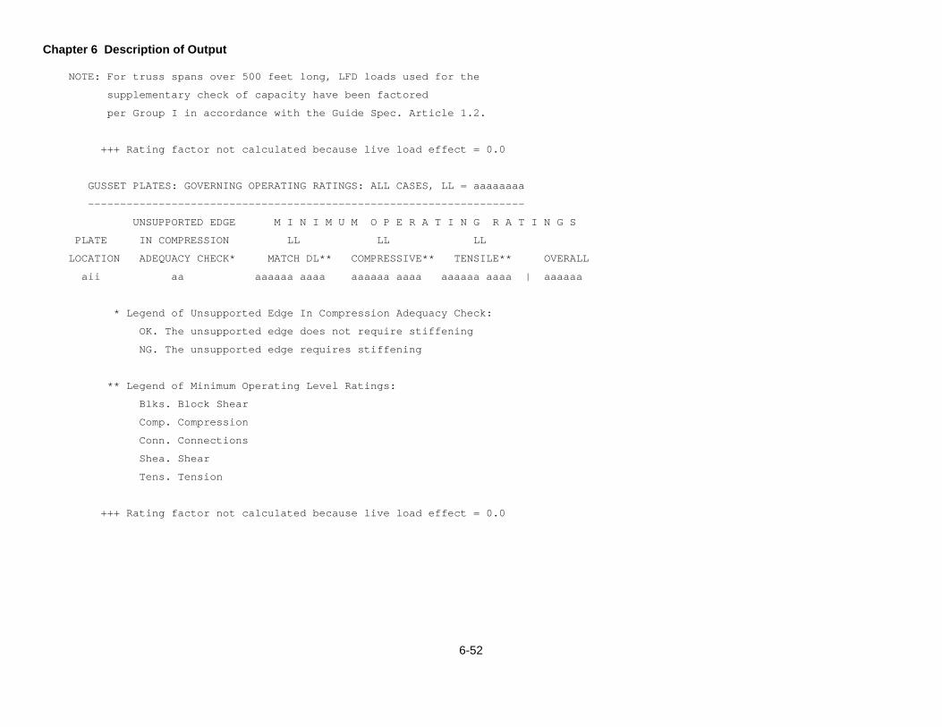
Chapter 6 Description of Output
6-52
NOTE: For truss spans over 500 feet long, LFD loads used for the
supplementary check of capacity have been factored
per Group I in accordance with the Guide Spec. Article 1.2.
+++ Rating factor not calculated because live load effect = 0.0
GUSSET PLATES: GOVERNING OPERATING RATINGS: ALL CASES, LL = aaaaaaaa
--------------------------------------------------------------------
UNSUPPORTED EDGE M I N I M U M O P E R A T I N G R A T I N G S
PLATE IN COMPRESSION LL LL LL
LOCATION ADEQUACY CHECK* MATCH DL** COMPRESSIVE** TENSILE** OVERALL
aii aa aaaaaa aaaa aaaaaa aaaa aaaaaa aaaa | aaaaaa
* Legend of Unsupported Edge In Compression Adequacy Check:
OK. The unsupported edge does not require stiffening
NG. The unsupported edge requires stiffening
** Legend of Minimum Operating Level Ratings:
Blks. Block Shear
Comp. Compression
Conn. Connections
Shea. Shear
Tens. Tension
+++ Rating factor not calculated because live load effect = 0.0

7-1
EXAMPLE PROBLEMS
This chapter contains seven (7) example problems to aid users in preparing data for their problems. Descriptions
of the bridge and of the required input, along with completed input forms, are given for each example. Refer to
Chapter 5 Input Descriptions when preparing data for your specific problem. The following seven example problems
are included in this chapter.
1. Example Problem 1 – Analysis and rating of a concrete T-beam bridge, CTB.
2. Example Problem 2 – Analysis and rating of an encased I-beam bridge, EIB.
3. Example Problem 3 – Analysis and rating of a multigirder steel bridge, GGG. Two-span continuous wide
flange beams with a 6 ¼ inch slab composite in the positive moment region.
4. Example Problem 4 – Analysis and rating of a girder-floorbeam-stringer type bridge, GFS, with some
fatigue prone details. Six span welded plate girder with a parabolic haunch and two in-span hinges.
5. Example Problem 5 – Analysis and rating of a single span thru truss-floorbeam-stringer type bridge, TFS,
including the gusset plate analysis and rating. The truss consists of six panels. It is symmetrical and the
center two panels have counters.
6. Example Problem 6 – An example that analyzes the bridge in Example Problem 5 using a separate data
file for the special live loadings data.
7. Example Problem 7 – Analysis and rating a single-span pony truss type bridge, TFS, including the gusset
plate analysis and rating, pony truss stability check at floorbeam location 2, live load = “K”, and load factor
method rating for members with or without eccentricity. The truss consists of seven panels and is
symmetrical.
The actual input data files and resulting output for the example problems are not listed in this manual, but input files
are included electronically with the executable program and can be run so that the output can be viewed.
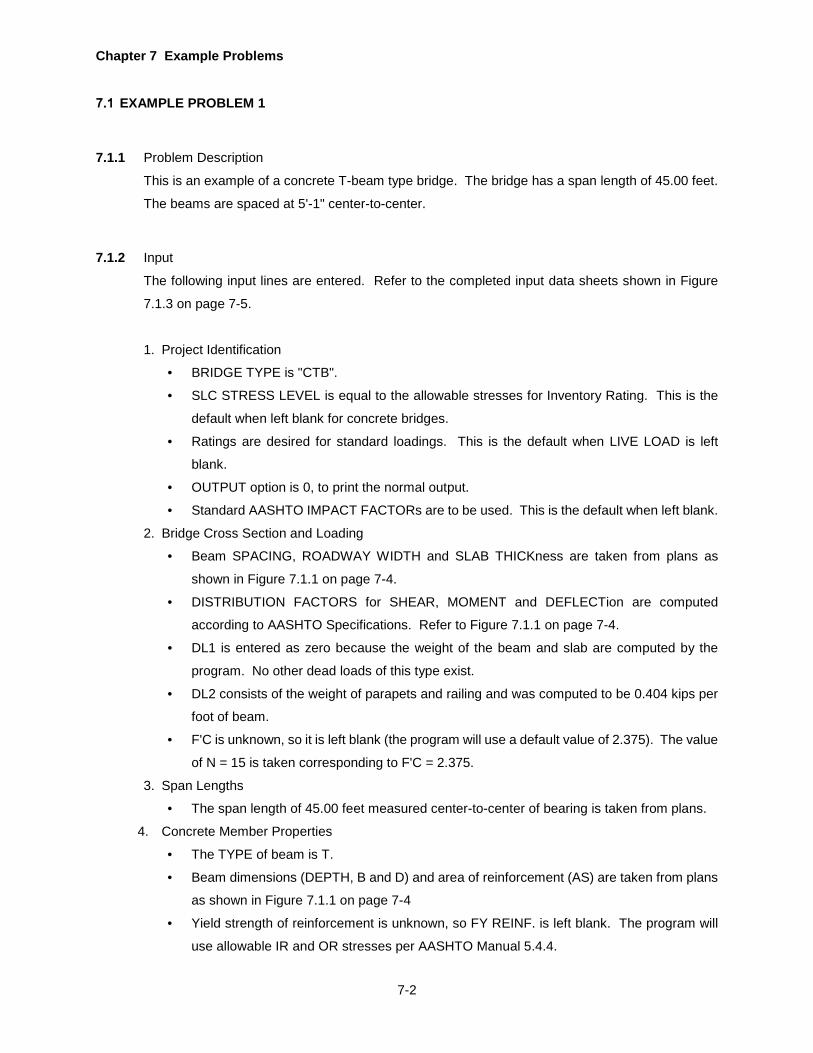
Chapter 7 Example Problems
7-2
EXAMPLE PROBLEM 1
7.1.1 Problem Description
This is an example of a concrete T-beam type bridge. The bridge has a span length of 45.00 feet.
The beams are spaced at 5'-1" center-to-center.
7.1.2 Input
The following input lines are entered. Refer to the completed input data sheets shown in Figure
7.1.3 on page 7-5.
1. Project Identification
• BRIDGE TYPE is "CTB".
• SLC STRESS LEVEL is equal to the allowable stresses for Inventory Rating. This is the
default when left blank for concrete bridges.
• Ratings are desired for standard loadings. This is the default when LIVE LOAD is left
blank.
• OUTPUT option is 0, to print the normal output.
• Standard AASHTO IMPACT FACTORs are to be used. This is the default when left blank.
2. Bridge Cross Section and Loading
• Beam SPACING, ROADWAY WIDTH and SLAB THICKness are taken from plans as
shown in Figure 7.1.1 on page 7-4.
• DISTRIBUTION FACTORS for SHEAR, MOMENT and DEFLECTion are computed
according to AASHTO Specifications. Refer to Figure 7.1.1 on page 7-4.
• DL1 is entered as zero because the weight of the beam and slab are computed by the
program. No other dead loads of this type exist.
• DL2 consists of the weight of parapets and railing and was computed to be 0.404 kips per
foot of beam.
• F'C is unknown, so it is left blank (the program will use a default value of 2.375). The value
of N = 15 is taken corresponding to F'C = 2.375.
3. Span Lengths
• The span length of 45.00 feet measured center-to-center of bearing is taken from plans.
4. Concrete Member Properties
• The TYPE of beam is T.
• Beam dimensions (DEPTH, B and D) and area of reinforcement (AS) are taken from plans
as shown in Figure 7.1.1 on page 7-4
• Yield strength of reinforcement is unknown, so FY REINF. is left blank. The program will
use allowable IR and OR stresses per AASHTO Manual 5.4.4.

Chapter 7 Example Problems
7-3
5. Stirrup Details
• Stirrups consist of #4 bars with a yield strength of 33 ksi.
• The first stirrup is 4 inches from the centerline of bearing.
• The next six stirrups are spaced 9 inches apart.
• Four more stirrups are spaced 12 inches apart followed by four stirrups at 18 inches, one
stirrup at 20 inches and three stirrups at 24 inches.

Chapter 7 Example Problems
7-4
Figure 7.1.1 Example Problem 1 - Details
CONCRETE T-BEAM BRIDGE CROSS SECTION
DL2DL2
Input DL1: None.
Input DL2: Weight of parapet, sidewalks, overlay and utilities per foot length of T-beam.
0.5" Concrete IntegralWearing Surface
Width for DL2
Note: The dead loads due to the weight of the slab (including integral wearing surface) and the weightof the beam are computed by the program and added to the input DL1.
Beam Spacing
30'
5' - 1"(TYP.)
17.5"
8.5"
INTEGRAL WEARING SURFACE *
*The program default forIntegral Wearing Surface is 0.5".
36.18"
15.62 in2
42"
TYPICAL T-BEAM
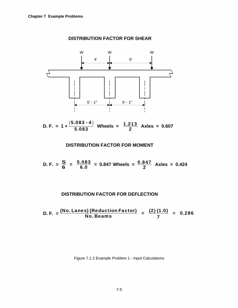
Chapter 7 Example Problems
7-5
Figure 7.1.2 Example Problem 1 - Input Calculations
DISTRIBUTION FACTOR FOR SHEAR
4'
5' - 1"5' - 1"
6'
W W W
D. F. = 1 + ( )5.083 - 45.083 Wheels = 1.213
2 Axles = 0.607
DISTRIBUTION FACTOR FOR MOMENT
D. F. = S6 Wheels = 0.8472 Axles = 0.424= 5.083
6.0 = 0.847
DISTRIBUTION FACTOR FOR DEFLECTION
D. F. = (No. Lanes) (Reduction Factor) (2) (1.0)= = 0.286No. Beams 7

Chapter 7 Example Problems
7-6
Figure 7.1.3 Example Problem 1 - Input
COUNTY
17
PRO
GR
AMID
ENT
STR
UC
TUR
E ID
ENTI
FIC
ATIO
N
STAT
ER
OU
TED
ESC
RIP
TIO
N
4548
5154
5760
67
BRID
GE
TYPE
=B
RR
AT
913
1721
SEG
MEN
TO
FFSE
T
IMPACTFACTOR
GAGEDISTANCE
PASSINGDISTANCE
63
PRO
JEC
T ID
ENTI
FIC
ATIO
N
15
DEC
KW
IDTH
DIS
TRIB
UTI
ON
FAC
TOR
S
MO
MEN
T
4751
5362
70
UNIT WEIGHT DECK CONC
913
1721
DEF
LEC
T
6674
BRID
GE
CR
OSS
SEC
TIO
N A
ND
LO
ADIN
G
SHEA
R
2529
3342
DL1
F'C
12
1
CONT
7
SPAN
LEN
GTH
S
2
SLC
LEVE
L
5253
LANESLIVE LOADOUTPUT
FATIGUE 6465
66
CONC DECKSPEC
REDISTDIRECT 68
S OVERFACTOR
OVE
R-
HAN
GO
RSP
ACIN
G
CL
OF
GIR
DER
OR
TR
USS
TO C
UR
B
RO
AD-
WAY
WID
TH
SLAB
THIC
KH
AUN
CH
37
DL2
BRID
GE
DEA
D L
OAD
S
N
SYMMETRYLL LOCAT
NO OFPANELS
END COND
5455
5758
59CORS
HIN
GE
AT
TEMPCHANGE
65
STR
ING
ERD
L1
FLO
OR
-BE
AMD
L1
1
19
611
1621
3
HIN
GE
LOC
ATIO
NS
24
2631
3641
67
85
4651
5661
66
1011
1213
14
END BRG
14
00
27
00
00
00
14
AM
EX
EP
LO
BP
RM
LE
1B
CT
0
50
83
00
00
60
70
42
40
28
60
85
00
00
00
40
40
23
75
15
45
00
9
1217
22
34
2732
3742
67
85
4752
5762
6772
1011
1213
1415
BAR
7BR
IDG
E AN
ALYS
IS A
ND
RAT
ING
PEN
NSY
LVAN
IA D
EPAR
TMEN
T O
F TR
ANSP
OR
TATI
ON
BUR
EAU
OF
INFO
RM
ATIO
N S
YSTE
MS
Form
1 o
f 9
71
END PANEL 72
HYB

Chapter 7 Example Problems
7-7
Figure 7.1.3 Example Problem 1 - Input (Cont.)
12D
EP
TH
TYPE
610
1418
D
CO
NC
RE
TE M
EM
BE
R P
RO
PE
RTI
ES
BA
S
2628
3440
A'S
D'
1
STI
RR
UP
AR
EA
68
13
LOC
ATI
ON
STI
RR
UP
DE
TAIL
S
fsy
SP
AC
ING
22
FYREINFA
LLO
WA
BLE
Fs
AV
31
IRO
R
ST DET 3539
SPECS
ALPHA
42
INT WEARSURFACE
1823
LOC
ATI
ON
SP
AC
ING
2833
LOC
ATI
ON
SP
AC
ING
3843
LOC
ATI
ON
SP
AC
ING
4853
LOC
ATI
ON
SP
AC
ING
5863
LOC
ATI
ON
SP
AC
ING
T4
20
01
75
03
61
81
56
23
3Y
00
00
23
30
00
00
04
33
00
00
98
34
00
02
18
38
00
08
18
34
10
00
02
50
61
00
04
2
BA
R7
BR
IDG
E A
NA
LYS
IS A
ND
RA
TIN
GP
EN
NS
YLV
AN
IA D
EP
AR
TME
NT
OF
TRA
NS
PO
RTA
TIO
NB
UR
EA
U O
F IN
FOR
MA
TIO
N S
YS
TEM
SFo
rm 3
of 9
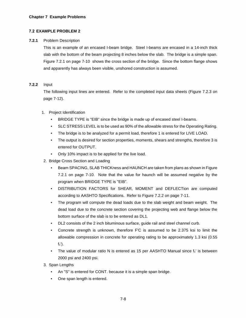
Chapter 7 Example Problems
7-8
EXAMPLE PROBLEM 2
7.2.1 Problem Description
This is an example of an encased I-beam bridge. Steel I-beams are encased in a 14-inch thick
slab with the bottom of the beam projecting 8 inches below the slab. The bridge is a simple span.
Figure 7.2.1 on page 7-10 shows the cross section of the bridge. Since the bottom flange shows
and apparently has always been visible, unshored construction is assumed.
7.2.2 Input
The following input lines are entered. Refer to the completed input data sheets (Figure 7.2.3 on
page 7-12).
1. Project Identification
• BRIDGE TYPE is "EIB" since the bridge is made up of encased steel I-beams.
• SLC STRESS LEVEL is to be used as 90% of the allowable stress for the Operating Rating.
• The bridge is to be analyzed for a permit load, therefore 1 is entered for LIVE LOAD.
• The output is desired for section properties, moments, shears and strengths, therefore 3 is
entered for OUTPUT.
• Only 10% impact is to be applied for the live load.
2. Bridge Cross Section and Loading
• Beam SPACING, SLAB THICKness and HAUNCH are taken from plans as shown in Figure
7.2.1 on page 7-10. Note that the value for haunch will be assumed negative by the
program when BRIDGE TYPE is "EIB".
• DISTRIBUTION FACTORS for SHEAR, MOMENT and DEFLECTion are computed
according to AASHTO Specifications. Refer to Figure 7.2.2 on page 7-11.
• The program will compute the dead loads due to the slab weight and beam weight. The
dead load due to the concrete section covering the projecting web and flange below the
bottom surface of the slab is to be entered as DL1.
• DL2 consists of the 2 inch bituminous surface, guide rail and steel channel curb.
• Concrete strength is unknown, therefore F'C is assumed to be 2.375 ksi to limit the
allowable compression in concrete for operating rating to be approximately 1.3 ksi (0.55
fc’).
• The value of modular ratio N is entered as 15 per AASHTO Manual since fc’ is between
2000 psi and 2400 psi.
3. Span Lengths
• An "S" is entered for CONT. because it is a simple span bridge.
• One span length is entered.

Chapter 7 Example Problems
7-9
4. Concrete Member Properties
• Since "Y" is entered for CONC DECK in the Project Identification line, this line must be
entered. The values entered here do not contribute anything to the rating analysis since
the longitudinal reinforcement in the concrete deck is not considered for a positive moment
section. The bridge type "EIB" can only be a simple span bridge and thus all sections are
subjected to positive moment only.
• An "S" is entered for TYPE and the rest of the line is left blank.
• If "Y" is not entered for CONC DECK, this line should not be entered.
• For bridge type "EIB", CONC DECK can be entered as "N" and this line can be eliminated
from the input.
5. Steel Member Properties
• All properties are for a steel beam, therefore "G" is entered for G F OR S.
• Since SYMMETRY is not entered as "Y", member properties for the entire beam must be
entered. However, the cross section of the beam is constant throughout its length,
therefore only one line of data is required.
• The SPAN NO is 1.
• The RANGE is equal to the span length.
• The SECT TYPE is "W" because the cross section is a wide flange beam W18x35.
• The WF BEAM M OF I, WF BEAM AREA, FLANGE THICK, FLANGE WIDTH, WF BEAM
DEPTH and WEB THICK are entered for the wide flange beam.
• Since the bottom flange of the encased beam has always been visible, an unshored
construction is assumed. COMPOSITE code is entered as "N" to indicate an unshored
construction.
• The yield strength of the beam is assumed to be 33 ksi.
• For bridge type "EIB", CONC DECK can be entered as "N" and this line can be eliminated
from the input.
6. Special Live Loads
• The permit load consists of a load of five axles and axle spacings as entered.
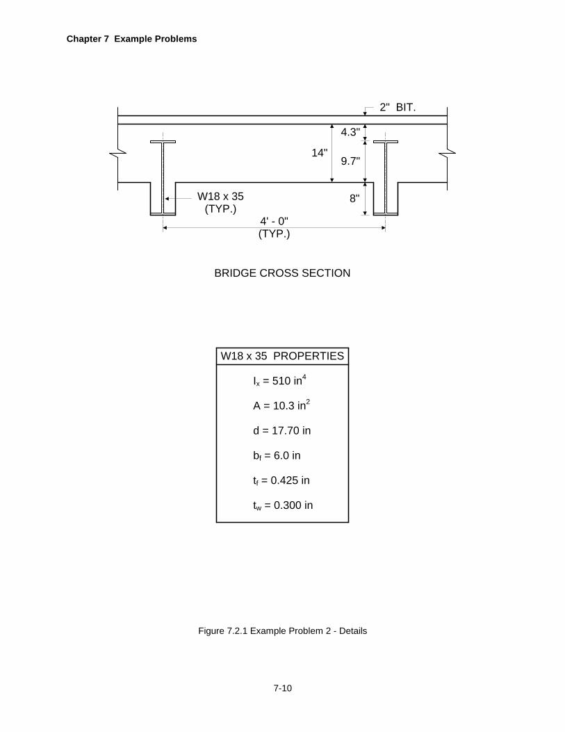
Chapter 7 Example Problems
7-10
Figure 7.2.1 Example Problem 2 - Details
4' - 0"(TYP.)
W18 x 35(TYP.)
8"
9.7"
4.3"
14"
2" BIT.
BRIDGE CROSS SECTION
W18 x 35 PROPERTIES
Ix = 510 in4
A = 10.3 in2
d = 17.70 in
bf = 6.0 in
tf = 0.425 in
tw = 0.300 in
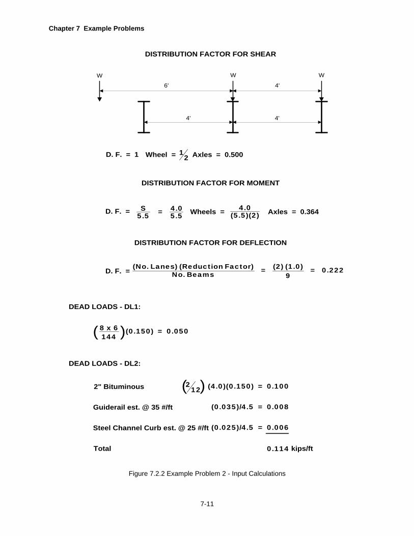
Chapter 7 Example Problems
7-11
Figure 7.2.2 Example Problem 2 - Input Calculations
DISTRIBUTION FACTOR FOR SHEAR
6'
4'4'
4'
W W W
D. F. = 1 Wheel = 12 Axles = 0.500
DISTRIBUTION FACTOR FOR MOMENT
D. F. = S5.5 Wheels = 4.0
(5.5)(2) Axles = 0.364= 4.05.5
DISTRIBUTION FACTOR FOR DEFLECTION
D. F. = (No. Lanes) (Reduction Factor) (2) (1.0)= = 0.222No. Beams 9
DEAD LOADS - DL1:
DEAD LOADS - DL2:
8 x 6 (0.150) = 0.050144( )
2" Bituminous 212( ) (4.0)(0.150) = 0.100
Guiderail est. @ 35 #/ft (0.035)/4.5 = 0.008
Steel Channel Curb est. @ 25 #/ft (0.025)/4.5 = 0.006
Total 0.114 kips/ft
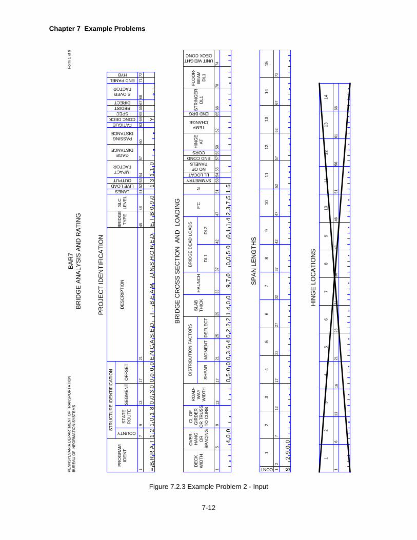
Chapter 7 Example Problems
7-12
Figure 7.2.3 Example Problem 2 - Input
COUNTY
17
PRO
GR
AMID
ENT
STR
UC
TUR
E ID
ENTI
FIC
ATIO
N
STAT
ER
OU
TED
ESC
RIP
TIO
N
4548
5154
5760
67
BRID
GE
TYPE
=B
RR
AT
913
1721
SEG
MEN
TO
FFSE
T
IMPACTFACTOR
GAGEDISTANCE
PASSINGDISTANCE
63
PRO
JEC
T ID
ENTI
FIC
ATIO
N
15
DEC
KW
IDTH
DIS
TRIB
UTI
ON
FAC
TOR
S
MO
MEN
T
4751
5362
70
UNIT WEIGHT DECK CONC
913
1721
DEF
LEC
T
6674
BRID
GE
CR
OSS
SEC
TIO
N A
ND
LO
ADIN
G
SHEA
R
2529
3342
DL1
F'C
12
19
CONT
712
1722
3
SPAN
LEN
GTH
S
24
2732
3742
67
85
SLC
LEVE
L
5253
LANESLIVE LOADOUTPUT
FATIGUE 6465
66
CONC DECKSPEC
REDISTDIRECT 68
S OVERFACTOR
OVE
R-
HAN
GO
RSP
ACIN
G
CL
OF
GIR
DER
OR
TR
USS
TO C
UR
B
RO
AD-
WAY
WID
TH
SLAB
THIC
KH
AUN
CH
37
DL2
BRID
GE
DEA
D L
OAD
S
N
SYMMETRYLL LOCAT
NO OFPANELS
END COND
5455
5758
59CORS
HIN
GE
AT
TEMPCHANGE
65
STR
ING
ERD
L1
FLO
OR
-BE
AMD
L1
4752
5762
6772
1011
1213
1415
1
19
611
1621
3
HIN
GE
LOC
ATIO
NS
24
2631
3641
67
85
4651
5661
66
1011
1213
14
END BRG
12
10
18
00
00
30
00
CA
EN
DS
EB
EI
-A
MN
BE
I3
40
00
50
00
36
40
22
21
40
00
05
00
11
42
37
51
5
29
00
UH
OS
DR
E0
09
11
10
Y
97
0
SPEN
NSY
LVAN
IA D
EPAR
TMEN
T O
F TR
ANSP
OR
TATI
ON
BUR
EAU
OF
INFO
RM
ATIO
N S
YSTE
MS
Form
1 o
f 9BA
R7
BRID
GE
ANAL
YSIS
AN
D R
ATIN
G
71
END PANEL 72
HYB
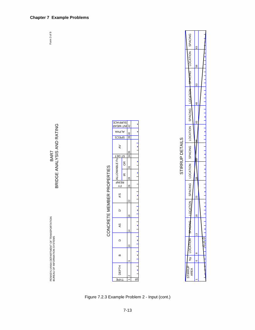
Chapter 7 Example Problems
7-13
Figure 7.2.3 Example Problem 2 - Input (cont.)
12D
EP
TH
TYPE
610
1418
D
CO
NC
RE
TE M
EM
BE
R P
RO
PE
RTI
ES
BA
S
2628
3440
A'S
D'
1
STI
RR
UP
AR
EA
68
13
LOC
ATI
ON
STI
RR
UP
DE
TAIL
S
fsy
SP
AC
ING
22
FYREINFA
LLO
WA
BLE
Fs
AV
31
IRO
R
ST DET 3539
SPECS
ALPHA
42
INT WEARSURFACE
1823
LOC
ATI
ON
SP
AC
ING
2833
LOC
ATI
ON
SP
AC
ING
3843
LOC
ATI
ON
SP
AC
ING
4853
LOC
ATI
ON
SP
AC
ING
5863
LOC
ATI
ON
SP
AC
ING
S
00
0
BA
R7
BR
IDG
E A
NA
LYS
IS A
ND
RA
TIN
GP
EN
NS
YLV
AN
IA D
EP
AR
TME
NT
OF
TRA
NS
PO
RTA
TIO
NB
UR
EA
U O
F IN
FOR
MA
TIO
N S
YS
TEM
SFo
rm 3
of 9
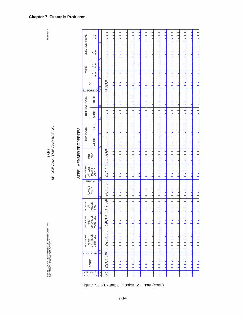
Chapter 7 Example Problems
7-14
Figure 7.2.3 Example Problem 2 - Input (cont.)
12
STEE
L M
EMBE
R P
RO
PER
TIES
38
WF
BEA
MM
OF
IO
R A
NG
LEVE
RT
LEG
1621
WF
BEA
MAR
EAO
R A
NG
LEH
OR
Z L
EG
26
FLAN
GE
WID
TH
31
FLAN
GE
OR
ANG
LETH
ICK
VARIES
RAN
GE
WF
BEA
MO
R W
EBPL
ATE
DEP
TH
WEB
THIC
KTH
ICK
WID
TH
G F OR SSPAN NO
9
SECT TYPE
3237
4246
THIC
KW
IDTH
5155
60
COMPOSITE 6164
6770
75
TOP
PLA
TEBO
TTO
M P
LATE
FYFY TO
PFY BO
TC
GTO
PC
GBO
T
HYB
RID
UN
SYM
MET
RIC
AL
G1
29
00
W1
00
05
13
00
45
02
06
00
01
70
73
00
00
30
3N
BAR
7BR
IDG
E AN
ALYS
IS A
ND
RAT
ING
PEN
NSY
LVAN
IA D
EPAR
TMEN
T O
F TR
ANSP
OR
TATI
ON
BUR
EAU
OF
INFO
RM
ATIO
N S
YSTE
MS
Form
6 o
f 9

Chapter 7 Example Problems
7-15
Figure 7.2.3 Example Problem 2 - Input (cont.)
12
SP LL NO
45
914
CO
NC
LOA
DM
OM
EN
T
LAN
E L
OA
DIN
G
UN
IFO
RM
LAN
ELO
AD
2226
19
GAGEDISTANCE
NUMBEROF AXLES3% INCR
CO
NC
LOA
DS
HE
AR
PASSINGDISTANCE
25
VARY LAST
MA
XA
XLE
DIS
T
1
TRU
CK
LO
AD
8
AX
LELO
AD
5DIS
TA
XLE
LOA
D
12
DIS
TA
XLE
LOA
D
15
DIS
TA
XLE
LOA
D
19
DIS
TA
XLE
LOA
D
22
DIS
TA
XLE
LOA
D
40
DIS
TA
XLE
LOA
D
47
DIS
TA
XLE
LOA
D
54
DIS
T
SP
EC
IAL
LIV
E L
OA
DIN
G
Not
e:
Bot
h th
e La
ne L
oad
and
the
Truc
k Lo
ad m
ust b
e de
scrib
ed a
sa
set f
or e
ach
of th
e sp
ecia
l liv
e lo
ads.
2629
3336
4350
BA
R7
BR
IDG
E A
NA
LYS
IS A
ND
RA
TIN
GP
EN
NS
YLV
AN
IA D
EP
AR
TME
NT
OF
TRA
NS
PO
RTA
TIO
NB
UR
EA
U O
F IN
FOR
MA
TIO
N S
YS
TEM
SFo
rm 9
of 9
10
5
10
00
10
11
55
00
41
55
02
20
15
50
04
15
50

Chapter 7 Example Problems
7-16
EXAMPLE PROBLEM 3
7.3.1 Problem Description
This is an example of a multigirder bridge. A two-span continuous girder bridge with a 6½" concrete
deck is analyzed to determine if it could be rated for the HS20 loading. Figure 7.3.1 on page 7-18
shows some of the basic details for this bridge.
7.3.2 Input
The following input lines are entered. Refer to the completed input data sheets (Figure 7.3.3 on
page 7-22
1. Project Identification
• The BRIDGE TYPE is "GGG".
• The SLC LEVEL is 25% above the allowable stresses at the Inventory Rating, I15.
• Analysis is desired for the HS20 loading only, therefore a "B" is coded for LIVE LOAD.
• A "0" is coded for OUTPUT so that tables of moments, shears, stresses, deflections, axial
force and ratings will be printed at various sections of a member.
• Standard AASHTO IMPACT FACTORs are to be used. • Standard Gage Distance (6 feet) and Passing Distance (2 feet) are to be used. • FATIGUE = Y. • CONCRETE DECK = Y.
2. Bridge Cross Section and Loading
• Girder SPACING, SLAB THICKness (with ½" of integral wearing surface added) and
HAUNCH are taken from plans as shown in Figure 7.3.1on page7-18.
• DISTRIBUTION FACTORS for SHEAR, MOMENT and DEFLECTion are computed per
AASHTO Specifications. Refer to Figure 7.3.2 on page 7-20.
• DL1 is calculated as shown on Figure 7.3.2 on page 7-20. The weight of the beam and
slab will be computed by the program.
• DL2 consists of the weight of parapets, railing and future paving and was computed as
shown in Figure 7.3.2 on page 7-20.
• F’C of 3.0 ksi and N of 10 are taken from design computations.
• The bridge is symmetric, so SYMMETRY is entered as "Y".
3. Span Lengths
• A "C" is entered for CONT. because the girders are continuous.
• Both span lengths are entered.
4. Concrete Member
• Fy REINF = 50 ksi

Chapter 7 Example Problems
7-17
5. Steel Member Properties
• All properties are for a girder, so "G" is coded for G F OR S.
• If SYMMETRY is entered as “Y” in the BRIDGS CROSS SECTION AND LOADING line,
then the member properties for one-half the entire length of the girder are entered, i.e. only
member properties in span 1 needs to be entered.
• Member properties are entered for SPAN NO. 1.
• The RANGE for each segment is the distance from the left end of each span to the right
end of the segment being described.
• The SECT TYPE is "W" because the cross section is a wide flange beam W36x135.
• The WF BEAM M OF I, WF BEAM AREA, FLANGE THICK, FLANGE WIDTH, WF BEAM
DEPTH and WEB THICK are entered for the wide flange beam.
• Each segment is specified either composite or non-composite by entering a "Y" or "N" for
COMPOSITE.
• The last range for the properties is equal to the first span length.
• Refer to Figure 7.3.1 on page 7-18 for the girder elevation sketch.
6. Lateral Brace Points and stiffener Spacings
• If SYMMETRY is entered as “Y” in the BRIDGS CROSS SECTION AND LOADING line,
then the lateral brace points and stiffener spacings for one-half the entire length of the
girder shall be entered, i.e. only the lateral brace points and stiffener spacings in span 1
needs to be entered.
7. Fatigue Data
• The bridge was built in 1956.
• The ADTT data for the last two counts are known, so the program will calculate the past
growth factor for ADTT.
• Future growth factor is assumed to be 5%.
• The structure is redundant.
• One Lane Distribution Factor is taken as girder spacing divided by 14 per AASHTO
Specifications Table 3.23.1.
8. Girder Fatigue Detail
• Fatigue prone details are described by entering the horizontal and vertical distances of
their locations and their AASHTO Categories.
• Detail locations and categories entered for this example problem are for illustration purpose
only. These details may not exist in this bridge.
• If SYMMETRY is entered as “Y” in the BRIDGS CROSS SECTION AND LOADING line,
then the last section entered here must be the center of the bridge even through there is
no fatigue detail.
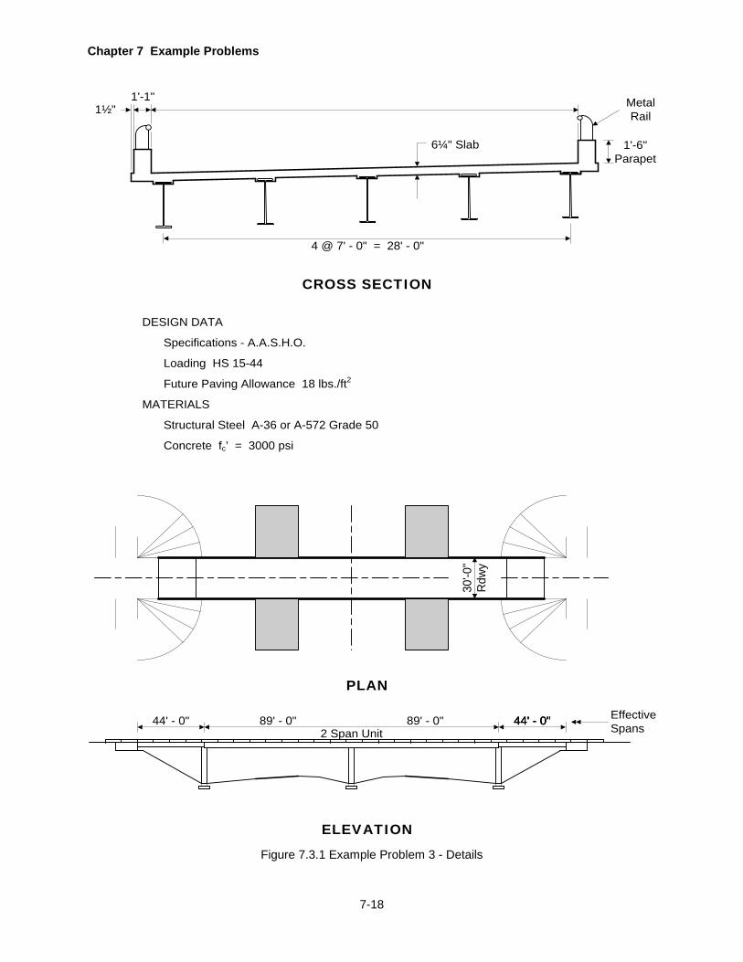
Chapter 7 Example Problems
7-18
Figure 7.3.1 Example Problem 3 - Details
CROSS SECTION
1'-1"1½"
4 @ 7' - 0" = 28' - 0"
1'-6"Parapet
MetalRail
6¼" Slab
DESIGN DATA
Specifications - A.A.S.H.O.
Loading HS 15-44
Future Paving Allowance 18 lbs./ft2
MATERIALS
Structural Steel A-36 or A-572 Grade 50
Concrete fc’ = 3000 psi
30'-0
"R
dwy
PLAN
ELEVATION
89' - 0" 89' - 0"2 Span Unit
44' - 0" 44' - 0" EffectiveSpans
44' - 0"44' - 0"

Chapter 7 Example Problems
7-19
Figure 7.3.1 Example Problem 3 - Details (cont.)
UNSHORED CONSTRUCTION
62' - 9" 62' - 9"CompositeComposite
16' - 7½" 16' - 7½"19' - 3"
W36 X 135 - A-36 W36 X 135 - A-36W36 X 135 - A-572 (GR. 50)
89' - 0" 89' - 0"22' - 3" 22' - 3" 22' - 3" 22' - 3" 22' - 3" 22' - 3" 22' - 3" 22' - 3"
Bracing
Spacing
A
A
B
B
A
A
10" x 5/8" Cover Plate T & B
75"
W36 X 135
LONGITUDINAL SECTION
SECTION A-A
W36 X 135
10"
10" x 5/8" Cover
Plate T & B
SECTION B-B
FATIGUE DATA
Light Traffic - 100,000 cycles
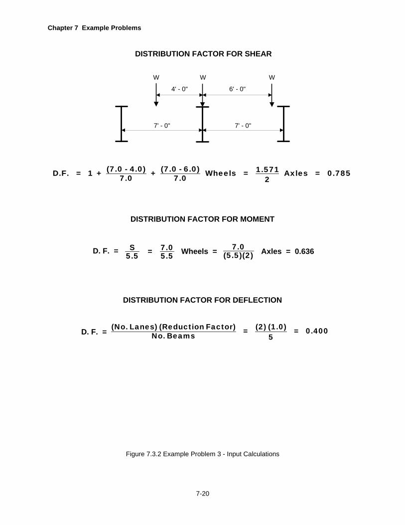
Chapter 7 Example Problems
7-20
Figure 7.3.2 Example Problem 3 - Input Calculations
DISTRIBUTION FACTOR FOR SHEAR
4' - 0"
7' - 0"7' - 0"
6' - 0"
W W W
DISTRIBUTION FACTOR FOR MOMENT
D. F. = S5.5 Wheels = 7.0
(5.5)(2) Axles = 0.636= 7.05.5
DISTRIBUTION FACTOR FOR DEFLECTION
D. F. = (No. Lanes) (Reduction Factor) (2) (1.0)= = 0.400No. Beams 5
(7.0 - 4.0) (7.0 - 6.0) 1.571D.F. = 1 + + Wheels = Axles = 0.7857.0 7.0 2
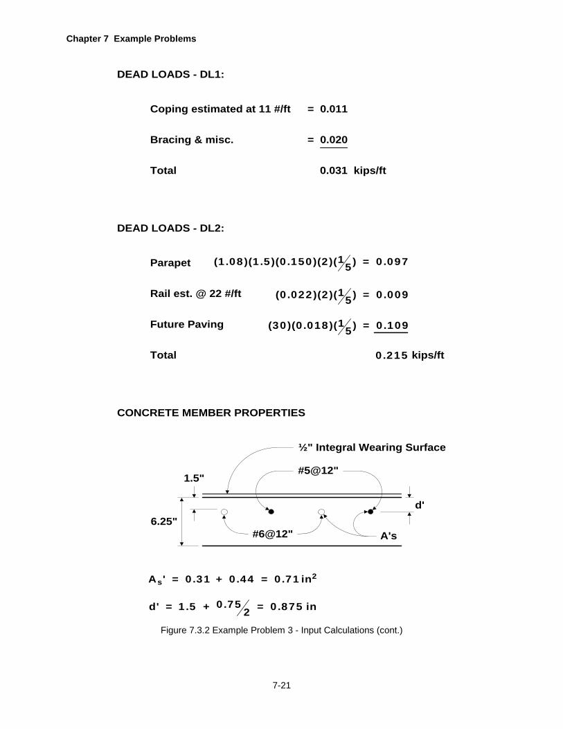
Chapter 7 Example Problems
7-21
Figure 7.3.2 Example Problem 3 - Input Calculations (cont.)
DEAD LOADS - DL1:
DEAD LOADS - DL2:
Parapet 1(1.08)(1.5)(0.150)(2)( ) = 0.0975
Rail est. @ 22 #/ft 1(0.022)(2)( ) = 0.0095
Future Paving
Total 0.215 kips/ft
Coping estimated at 11 #/ft
Bracing & misc.
Total
= 0.011
= 0.020
0.031 kips/ft
1(30)(0.018)( ) = 0.1095
CONCRETE MEMBER PROPERTIES
½" Integral Wearing Surface
#5@12"
#6@12"
d'
1.5"
6.25"A's
2sA ' = 0.31 + 0.44 = 0.71 in
0.75d' = 1.5 + = 0.875 in2

Chapter 7 Example Problems
7-22
COUNTY
17
PRO
GR
AMID
ENT
STR
UCTU
RE
IDEN
TIFI
CATI
ON
STAT
ER
OU
TED
ESC
RIPT
ION
4548
5154
5760
67
BRID
GE
TYPE
=B
RR
AT
913
1721
SEG
ME
NTO
FFSE
T
IMPACTFACTOR
GAGEDISTANCE
PASSINGDISTANCE
63
PR
OJE
CT
IDE
NTI
FIC
ATI
ON
15
DEC
KW
IDTH
DIS
TRIB
UTIO
N FA
CTO
RS
MO
MEN
T
4751
5362
70
UNIT WEIGHT DECK CONC
913
1721
DEF
LEC
T
6674
BR
IDG
E C
RO
SS
SE
CT
ION
AN
D L
OA
DIN
G
SHEA
R
2529
3342
DL1
F'C
12
19
CONT
712
1722
3
SP
AN
LE
NG
THS
24
2732
3742
67
85
SLC
LEV
EL
5253
LANESLIVE LOADOUTPUT
FATIGUE 6465
66
CONC DECKSPEC
REDISTDIRECT 68
S OVERFACTOR
OVE
R-
HAN
GO
RSP
ACI
NG
CL
OF
GIR
DER
OR
TR
USS
TO C
UR
B
RO
AD-
WAY
WID
TH
SLA
BTH
ICK
HAU
NCH
37
DL2
BRID
GE
DEA
D L
OAD
S
N
SYMMETRYLL LOCAT
NO OFPANELS
END COND
5455
5758
59CORS
HIN
GE
AT
65
STR
ING
ERD
L1
FLO
OR
-BE
AM
DL1
4752
5762
6772
1011
1213
1415
1
19
611
1621
3
HIN
GE
LO
CA
TIO
NS
24
2631
3641
67
85
4651
5661
66
1011
1213
14
END BRG
12
12
34
12
34
31
42
SP
2-
AN
EI
DF
LG
GG
G0
70
00
78
50
63
60
40
06
75
00
31
02
15
30
00
10
89
00
NB
EM
EA
I5
2B
Y
00
0
C
WA
Y
Y
89
00
PENN
SYL
VAN
IA D
EPA
RTM
ENT
OF
TRAN
SPO
RTA
TIO
NBU
REA
U O
F IN
FOR
MA
TIO
N S
YST
EMS
Form
1 o
f 12
BA
R7
BR
IDG
E A
NA
LYS
IS A
ND
RA
TIN
G
71
END PANELHYB
72
SKEW CORRECTION
FACTOR
PONY TRUSSPDF
COMPACT
7778
79 7978
77
GUSSETPATCH
UNSYM PIER
Figure 7.3.3 Example Problem 3 - Input
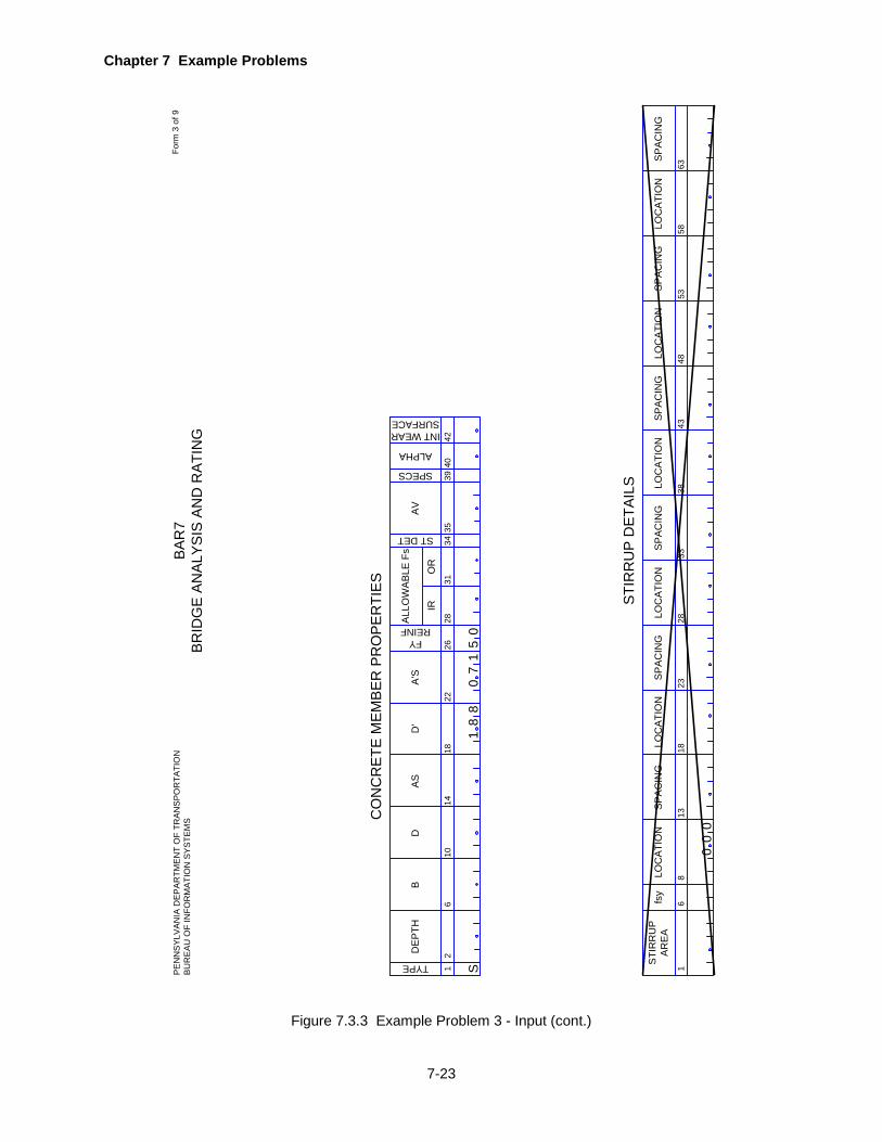
Chapter 7 Example Problems
7-23
Figure 7.3.3 Example Problem 3 - Input (cont.)
12D
EP
TH
TYPE
610
1418
D
CO
NC
RE
TE M
EM
BE
R P
RO
PE
RTI
ES
BA
S
2628
3440
A'S
D'
1
STI
RR
UP
AR
EA
68
13
LOC
ATI
ON
STI
RR
UP
DE
TAIL
S
fsy
SP
AC
ING
22
FYREINFA
LLO
WA
BLE
Fs
AV
31
IRO
R
ST DET 3539
SPECS
ALPHA
42
INT WEARSURFACE
1823
LOC
ATI
ON
SP
AC
ING
2833
LOC
ATI
ON
SP
AC
ING
3843
LOC
ATI
ON
SP
AC
ING
4853
LOC
ATI
ON
SP
AC
ING
5863
LOC
ATI
ON
SP
AC
ING
S
00
0
18
80
71
05
BA
R7
BR
IDG
E A
NA
LYS
IS A
ND
RA
TIN
GP
EN
NS
YLV
AN
IA D
EP
AR
TME
NT
OF
TRA
NS
PO
RTA
TIO
NB
UR
EA
U O
F IN
FOR
MA
TIO
N S
YS
TEM
SFo
rm 3
of 9
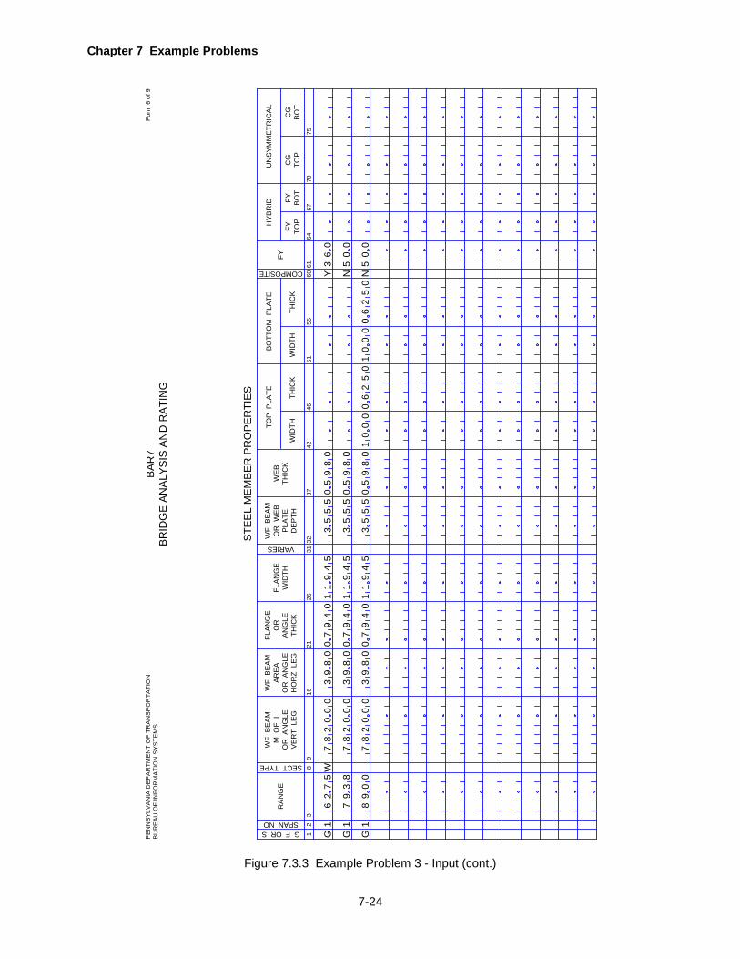
Chapter 7 Example Problems
7-24
Figure 7.3.3 Example Problem 3 - Input (cont.)
12
STE
EL
ME
MB
ER
PR
OP
ER
TIE
S
38
WF
BE
AM
M O
F I
OR
AN
GLE
VE
RT
LE
G
1621
WF
BE
AM
AR
EA
OR
AN
GLE
HO
RZ
LE
G
26
FLA
NG
E
WID
TH
31
FLA
NG
EO
RA
NG
LETH
ICK
VARIES
RA
NG
E
WF
BE
AM
OR
WE
BP
LATE
DE
PTH
WE
BTH
ICK
THIC
KW
IDTH
G F OR SSPAN NO
9
SECT TYPE
3237
4246
THIC
KW
IDTH
5155
60
COMPOSITE 6164
6770
75
TOP
PLA
TEB
OTT
OM
PLA
TEFY
FY TOP
FY BO
TC
GTO
PC
GB
OT
HY
BR
IDU
NS
YM
ME
TRIC
AL
G1
62
75
W2
00
08
38
09
74
09
01
45
93
55
55
80
90
60
3Y
71
N N
50
0
50
0
G1
G1
00
899
73
82
00
08
7
20
00
87
38
09
38
09
74
09
01
45
91
74
09
01
45
91
35
55
58
09
0
35
55
58
09
00
00
10
00
16
50
20
65
02
0
BA
R7
BR
IDG
E A
NA
LYS
IS A
ND
RA
TIN
GP
EN
NS
YLV
AN
IA D
EP
AR
TME
NT
OF
TRA
NS
PO
RTA
TIO
NB
UR
EA
U O
F IN
FOR
MA
TIO
N S
YS
TEM
SFo
rm 6
of 9

Chapter 7 Example Problems
7-25
Figure 7.3.3 Example Problem 3 - Input (cont.)
13
LATE
RAL
BR
ACE
POIN
TS A
ND
STI
FFEN
ER S
PAC
ING
S
4
BRAC
E PO
INT
OR
STI
FFEN
ER
75
CODE
SPAC
ING
BRACING ORSTIFF CODESPAN NO.
1215
13CODE
2023
21CODE
2831
29CODENO. OF
SPACES
3639
37CODE
4447
45CODE
5255
53CODE
6063
61CODE
SPAC
ING
SPAC
ING
SPAC
ING
SPAC
ING
SPAC
ING
SPAC
ING
SPAC
ING
BRAC
E PO
INT
OR
STI
FFEN
ERBR
ACE
POIN
TO
R S
TIFF
ENER
BRAC
E PO
INT
OR
STI
FFEN
ERBR
ACE
POIN
TO
R S
TIFF
ENER
BRAC
E PO
INT
OR
STI
FFEN
ERBR
ACE
POIN
TO
R S
TIFF
ENER
BRAC
E PO
INT
OR
STI
FFEN
ER
BG
1C
18
90
0B
42
22
5
NO. OFSPACES
NO. OFSPACES
NO. OFSPACES
NO. OFSPACES
NO. OFSPACES
NO. OFSPACES
NO. OFSPACES
BAR
7BR
IDG
E AN
ALYS
IS A
ND
RAT
ING
PEN
NSY
LVAN
IA D
EPAR
TMEN
T O
F TR
ANSP
OR
TATI
ON
BUR
EAU
OF
INFO
RM
ATIO
N S
YSTE
MS
Form
7 o
f 9

Chapter 7 Example Problems
7-26
Figure 7.3.3 Example Problem 3 - Input (cont.)
12
DIS
TFR
OM
CL
BR
G
SPAN NO
712
14
GIR
DER
FAT
IGU
E D
ETAI
L
1
GR
OSS
VEH
ICLE
WEI
GH
T D
ISTR
IBU
TIO
N
6
MIN
1115
MAX
GR
OSS
VEH
ICLE
WEI
GH
T
1923
2AX
LE
NO
OF
SIN
GLE
UN
IT T
RU
CKS
1
YEAR
BUIL
T
59
1317
ADTT
FATI
GU
E D
ATA
YEAR
OR
GF
YEAR
2529
34
ADTT
2130
NO OFGVWD
YEAR
OR
GF
ADTT
PREV
IOU
S C
OU
NT
REC
ENT
CO
UN
TFU
TUR
E C
OU
NT
R OR N
ON
ELA
NE
DIS
TRFA
CTO
R
DIS
TFR
OM
BOTT
OM
CATEGORY
1921
DIS
TFR
OM
BOTT
OM
CATEGORY
2628
DIS
TFR
OM
BOTT
OM
CATEGORY
33
DIS
TFR
OM
BOTT
OM
CATEGORY
3AX
LE4
AXLE
2731
3AX
LE
NO
OF
SIN
GLE
UN
IT T
RU
CKS
4AX
LE5
OR
>AX
LE
19
56
10
06
08
91
20
88
89
00
50
00
50
R
1 1 1
62
75
00
0
00
98
38
97
63
0
B EEC
98
43
18
63
BAR
7BR
IDG
E AN
ALYS
IS A
ND
RAT
ING
PEN
NSY
LVAN
IA D
EPAR
TMEN
T O
F TR
ANSP
OR
TATI
ON
BUR
EAU
OF
INFO
RM
ATIO
N S
YSTE
MS
Form
8 o
f 9
Chapter 7 Example Problems
7-27
EXAMPLE PROBLEM 4
7.4.1 Problem Description
This is an example of a girder-floorbeam-stringer type (GFS) bridge. The main girder is a six-span
symmetrical plate girder with a parabolic haunch and two in-span hinges. The floorbeams have a
wide flange section between main girders and a straight haunch section in the overhang portion of
the deck. The bridge has some fatigue-prone details. The main girder and stringers are assumed
to act as composite sections both in the positive and negative moment regions. All structural steel
conforms to ASTM-A36-62T steel. Figure 7.4.1 on page 7-30 shows the details of the bridge.
7.4.2 Input
The following input lines are entered. Refer to the completed input data sheets shown in Figure
7.4.3 on page 7-34.
1. Project Identification
• The BRIDGE TYPE is "GFS".
• The SLC LEVEL is left blank since the Safe Load Capacity Ratings are not desired.
• "D" is entered for LANES indicating that the ratings are desired based on one lane loaded
as described later.
• The bridge is to be analyzed for the HS20 loading, therefore a "B" is coded for LIVE LOAD.
• OUTPUT option equal to 0 is used so that all computed values will be printed.
• Impact factor will be calculated by the program as per AASHTO Specifications.
• Fatigue analysis of certain details is requested.
• The bridge has a concrete deck, CONC DECK = “Y”.
2. Bridge Cross Section and Loading
• Bridge cross section dimensions are taken from plans.
• DISTRIBUTION FACTORS for stringer are computed as shown in Figure 7.4.2 on page 7-
32.
• SLAB THICKness varies from 8 inches to 8.5 inches across the deck. Total thickness of 9
inches is entered to get 8.5 inches effective thickness.
• DL1 is the dead load due to the weight of stiffeners and other hardware attached to the girder.
• DL2 is the dead load due to the weight of curb, parapet, railing, etc. as calculated and
shown in Figure 7.4.2 on page 7-32.
• F'C of 3.5 ksi and N of 8 are taken from design computations.
• The girder is symmetric about the centerline of pier 3, so a "Y" is coded for SYMMETRY. • STRINGER DL1 is blank assuming there is no DL1 for stringers. • FLOORBEAM DL1 is blank assuming there is no DL1 for floorbeams.
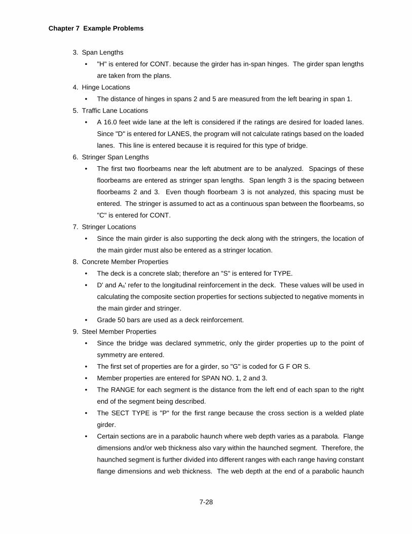
Chapter 7 Example Problems
7-28
3. Span Lengths
• "H" is entered for CONT. because the girder has in-span hinges. The girder span lengths
are taken from the plans.
4. Hinge Locations
• The distance of hinges in spans 2 and 5 are measured from the left bearing in span 1.
5. Traffic Lane Locations
• A 16.0 feet wide lane at the left is considered if the ratings are desired for loaded lanes.
Since "D" is entered for LANES, the program will not calculate ratings based on the loaded
lanes. This line is entered because it is required for this type of bridge.
6. Stringer Span Lengths
• The first two floorbeams near the left abutment are to be analyzed. Spacings of these
floorbeams are entered as stringer span lengths. Span length 3 is the spacing between
floorbeams 2 and 3. Even though floorbeam 3 is not analyzed, this spacing must be
entered. The stringer is assumed to act as a continuous span between the floorbeams, so
"C" is entered for CONT.
7. Stringer Locations
• Since the main girder is also supporting the deck along with the stringers, the location of
the main girder must also be entered as a stringer location.
8. Concrete Member Properties
• The deck is a concrete slab; therefore an "S" is entered for TYPE.
• D' and As' refer to the longitudinal reinforcement in the deck. These values will be used in
calculating the composite section properties for sections subjected to negative moments in
the main girder and stringer.
• Grade 50 bars are used as a deck reinforcement.
9. Steel Member Properties
• Since the bridge was declared symmetric, only the girder properties up to the point of
symmetry are entered.
• The first set of properties are for a girder, so "G" is coded for G F OR S.
• Member properties are entered for SPAN NO. 1, 2 and 3.
• The RANGE for each segment is the distance from the left end of each span to the right
end of the segment being described.
• The SECT TYPE is "P" for the first range because the cross section is a welded plate
girder.
• Certain sections are in a parabolic haunch where web depth varies as a parabola. Flange
dimensions and/or web thickness also vary within the haunched segment. Therefore, the
haunched segment is further divided into different ranges with each range having constant
flange dimensions and web thickness. The web depth at the end of a parabolic haunch

Chapter 7 Example Problems
7-29
only is to be entered. A "P" for input item VARIES will indicate that this range has a
parabolic haunch. The input of WEB PLATE DEPTH and a "P" for a given range will
indicate the end of a parabolic haunch. For example, the parabolic haunch in span 1 begins
at 81 feet and ends at 122 feet, but the web thickness changes at 103.5 feet. Therefore,
the segment between 81 feet and 122 feet is divided into two ranges, one ends at 103.5
feet and the other ends at 122 feet. The web depth is entered for a range of 122 feet since
it is the end of a parabolic haunch in span 1. The web depth at 103.5 feet will be calculated
by the program by assuming that the web depth varies from 108 inches to 144 inches
between 81 feet and 122 feet as a parabola.
• Each segment is specified as composite by entering a "Y" for COMPOSITE.
• The girder has a homogeneous section. Therefore, HYBRID FY's and UNSYMMETRICAL
CG's are not entered.
• Floorbeam 1 is a plate girder type section. Since the floorbeam has an overhang, at least
two ranges (one at 0.0) must be entered for the overhang portion. The range for the
overhang is entered as a negative value.
• Floorbeam 2 has a wide flange section between the main girders. The overhang portion
of floorbeam 2 is a plate girder section. Therefore, the entire member has been entered
as a plate girder with a SECT TYPE of "P". The wide flange portion has been approximated
by entering the flange properties as the TOP and BOTTOM PLATE and subtracting the
flange thicknesses from the beam depth to get the WEB PLATE DEPTH.
• The web depths of overhang portions of both the floorbeams vary as a straight haunch.
Therefore, an "S" is entered for VARIES for a range equal to -6.75 feet.
• The stringer is a wide flange beam without any cover plates. Therefore, the moment of
inertia, area, beam depth and web thickness are entered. It is also entered as a composite
section.
10. Lateral Brace Points and Stiffener Spacings
• The top flange for the entire girder is assumed to be continuously supported.
• The bottom flange brace points are taken from the plans and are entered for each span up
to span 3 only since the girder is symmetrical.
• The maximum stiffener spacing is 4.5. Therefore, total number of equal spaces closest to
the span length are entered with the remainder spaces near the support for each span.
The girder has a longitudinal stiffener and transverse stiffeners. "L" is entered for
STIFFENER CODE for the entire span.
• The value for NO. OF SPACES for BRACE POINTS for the overhang portion of the
floorbeam is entered as a negative indicating that this spacing is on the overhang portion.
• Stringers will be assumed unstiffened, top flange continuously braced and bottom flange
braced at the floorbeam supports.

Chapter 7 Example Problems
7-30
11. Fatigue Data
• The bridge was built in 1966.
• The past growth factor for ADTT is assumed as 3%.
• The most recent count for ADTT was taken in 1989 and the ADTT was 600 trucks per day
in one direction.
• The ADTT data for the year 1996 is estimated to be 790. The program will compute the
remaining life of the girder based on the future growth factor calculated from this estimate.
• The bridge has a non-redundant load path.
• The ONE LANE DISTR FACTOR is calculated to be 0.837 lanes (axles) by placing the
HS20 truck with one wheel right over the left main girder and the second wheel 6 feet away
to the right.
12. Girder Fatigue Detail
• Fatigue-prone details are determined from plans and are entered as shown on the input
form.
Typical Section
Figure 7.4.1 Example Problem 4 - Details
15"9"4' 0"12' 0"12' 0"4' 0"18"15"
24WF68
6' 2" 6' 2" 6' 2"6' 2" 6' 2"
6' 9"
2' 6"3' 6"
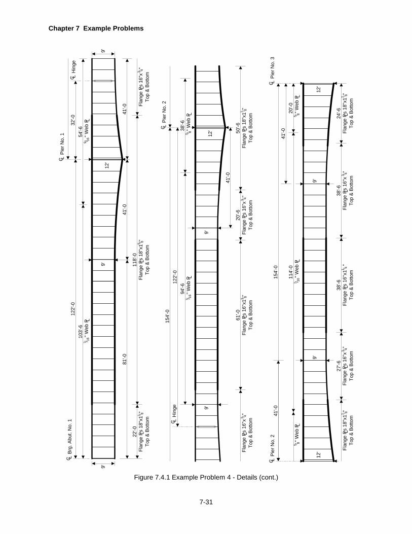
Chapter 7 Example Problems
7-31
Figure 7.4.1 Example Problem 4 - Details (cont.)
9'
C LBr
g. A
but.
No.
1
C LPi
er N
o. 1
122'
-010
3'-6
22'-0
Flan
ge P
s 18
"x1
"L
Top
& Bo
ttom
1 8/
"
Web
P L7 16/
54'-6
"
Web
P L9 16/
118'
-0Fl
ange
Ps
18"x
1 "
LTo
p &
Botto
m
5 8/
32'-0
C LH
inge
Flan
ge P
s 16
"x
"L
Top
& Bo
ttom
9'12
'
81'-0
41'-0
41'-0
9'
C LH
inge
Flan
ge P
s 16
"x
"L
Top
& Bo
ttom3 4/
9'
Flan
ge P
s 16
"x1
"L
Top
& Bo
ttom
3 8/61
'-020
'-6
Top
& Bo
ttom
LFl
ange
Ps
16"x
"
3 4/
3 4/
50'-6
Flan
ge P
s 18
"x1
"L
Top
& Bo
ttom
7 8/
41'-0
9'12
'C LPi
er N
o. 2
154'
-012
2'-0
94'-6
"
Web
P L7 16/
38'-6
"
Web
P L5 8/
C LPi
er N
o. 2
C LPi
er N
o. 3
27'-6
Top
& Bo
ttom
LFl
ange
Ps
16"x
"
3 4/
114'
-0
" W
eb P L
7 16/20
'-0
" W
eb P L
5 8/
Flan
ge P
s 18
"x1
"L
Top
& Bo
ttom
7 8/
"
Web
P L5 8/
154'
-0
24'-6
38'-6
38'-6
Top
& Bo
ttom
LFl
ange
Ps
16"x
"
3 4/
Top
& Bo
ttom
LFl
ange
Ps
16"x
1 "1 4/
Flan
ge P
s 18
"x1
"L
Top
& Bo
ttom
7 8/
12'
9'9'
12'
41'-0
41'-0
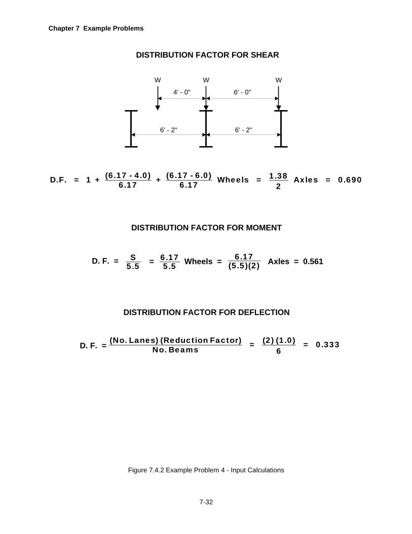
Chapter 7 Example Problems
7-32
Figure 7.4.2 Example Problem 4 - Input Calculations
DISTRIBUTION FACTOR FOR SHEAR
4' - 0"
6' - 2"6' - 2"
6' - 0"
W W W
DISTRIBUTION FACTOR FOR MOMENT
D. F. = S5.5 Wheels = 6.17
(5.5)(2) Axles = 0.561= 6.175.5
DISTRIBUTION FACTOR FOR DEFLECTION
D. F. = (No. Lanes) (Reduction Factor) (2) (1.0)= = 0.333No. Beams 6
(6.17 - 4.0) (6.17 - 6.0) 1.38D.F. = 1 + + Wheels = Axles = 0.6906.17 6.17 2
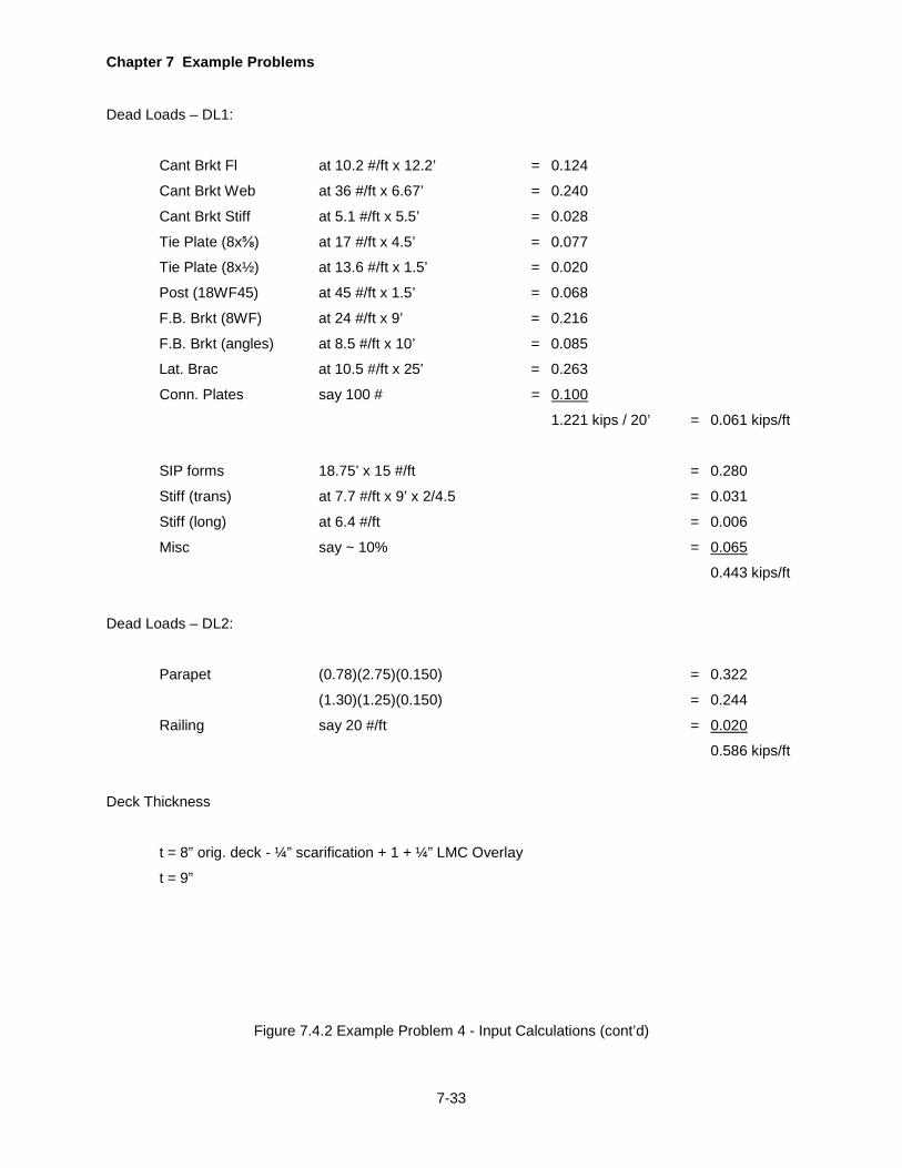
Chapter 7 Example Problems
7-33
Dead Loads – DL1:
Cant Brkt Fl at 10.2 #/ft x 12.2’ = 0.124
Cant Brkt Web at 36 #/ft x 6.67’ = 0.240
Cant Brkt Stiff at 5.1 #/ft x 5.5’ = 0.028
Tie Plate (8x⅝) at 17 #/ft x 4.5’ = 0.077
Tie Plate (8x½) at 13.6 #/ft x 1.5’ = 0.020
Post (18WF45) at 45 #/ft x 1.5’ = 0.068
F.B. Brkt (8WF) at 24 #/ft x 9’ = 0.216
F.B. Brkt (angles) at 8.5 #/ft x 10’ = 0.085
Lat. Brac at 10.5 #/ft x 25’ = 0.263
Conn. Plates say 100 # = 0.100
1.221 kips / 20’ = 0.061 kips/ft
SIP forms 18.75’ x 15 #/ft = 0.280
Stiff (trans) at 7.7 #/ft x 9’ x 2/4.5 = 0.031
Stiff (long) at 6.4 #/ft = 0.006
Misc say ~ 10% = 0.065
0.443 kips/ft
Dead Loads – DL2:
Parapet (0.78)(2.75)(0.150) = 0.322
(1.30)(1.25)(0.150) = 0.244
Railing say 20 #/ft = 0.020
0.586 kips/ft
Deck Thickness
t = 8” orig. deck - ¼” scarification + 1 + ¼” LMC Overlay
t = 9”
Figure 7.4.2 Example Problem 4 - Input Calculations (cont’d)

Chapter 7 Example Problems
7-34
Figure 7.4.3 Example Problem 4 - Input
COUNTY
17
PRO
GR
AMID
ENT
STR
UC
TUR
E ID
ENTI
FIC
ATIO
N
STAT
ER
OU
TED
ESC
RIP
TIO
N
4548
5154
5760
67
BRID
GE
TYPE
913
1721
SEG
MEN
TO
FFSE
T
IMPACTFACTOR
GAGEDISTANCE
PASSINGDISTANCE
63
PRO
JEC
T ID
ENTI
FIC
ATIO
N
15
DEC
KW
IDTH
DIS
TRIB
UTI
ON
FAC
TOR
S
MO
MEN
T
4751
5362
70
UNIT WEIGHT DECK CONC
913
1721
DEF
LEC
T
6674
BRID
GE
CR
OSS
SEC
TIO
N A
ND
LO
ADIN
G
SHEA
R
2529
3342
DL1
F 'C
12
19
CONT
712
1722
3
SPAN
LEN
GTH
S
24
2732
3742
67
85
SLC
LEVE
L
5253
LANESLIVE LOADOUTPUT
FATIGUE 6465
66
CONC DECKSPEC
REDISTDIRECT 68
S OVERFACTOR
OVE
R-
HAN
GO
RSP
ACIN
G
CL
OF
GIR
DER
OR
TR
USS
TO C
UR
B
RO
AD-
WAY
WID
TH
SLAB
THIC
KH
AUN
CH
37
DL2
BRID
GE
DEA
D L
OAD
S
N
SYMMETRYLL LOCAT
NO OFPANELS
END COND
5455
5758
59CORS
HIN
GE
AT
TEMPCHANGE
65
STR
ING
ERD
L1
FLO
OR
-BE
AMD
L1
4752
5762
6772
1011
1213
1415
1
19
611
1621
3
HIN
GE
LOC
ATIO
NS
24
2631
3641
67
85
4651
5661
66
1011
1213
14
END BRG
=B
RR
AT
PEN
NSY
LVAN
IA D
EPAR
TMEN
T O
F TR
ANSP
OR
TATI
ON
BUR
EAU
OF
INFO
RM
ATIO
N S
YSTE
MS
Form
1 o
f 9BA
R7
BRID
GE
ANAL
YSIS
AN
D R
ATIN
G
71
END PANEL 72
HYB
46
04
22
00
13
20
22
4R
T2
2U
CH
SY
LK
LG
LI
RV
EI
RS
F0
BD
YY
67
53
75
06
75
-3
06
90
05
61
03
20
03
39
00
04
00
04
30
58
63
50
08
Y
22
00
H5
40
01
15
14
00
54
00
15
40
01
20
12
0
54
01
06
07
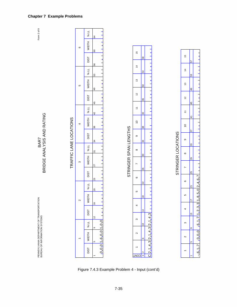
Chapter 7 Example Problems
7-35
Figure 7.4.3 Example Problem 4 - Input (cont’d)
19
TRA
FFIC
LA
NE
LO
CA
TIO
NS
12
111
CONT
610
1418
3
STR
ING
ER
SP
AN
LE
NG
THS
24
2630
3442
65
4650
5458
1213
14
1
111
59
1317
3
STR
ING
ER
LO
CA
TIO
NS
24
2129
3741
78
96
4549
5357
1213
1415
5
1
DIS
TW
IDTH
% L
L
1220
16
2
DIS
TW
IDTH
% L
L
2331
27
3
DIS
TW
IDTH
% L
L
3442
38
4
DIS
TW
IDTH
% L
L
4553
49
5
DIS
TW
IDTH
% L
L
5664
60
6
DIS
TW
IDTH
% L
L
22
78
9
38
1015
5
2533
10
00
00
01
60
01
C2
31
42
31
42
31
4
-6
17
00
06
17
31
23
51
80
62
47
BA
R7
BR
IDG
E A
NA
LYS
IS A
ND
RA
TIN
GP
EN
NS
YLV
AN
IA D
EP
AR
TME
NT
OF
TRA
NS
PO
RTA
TIO
NB
UR
EA
U O
F IN
FOR
MA
TIO
N S
YS
TEM
SFo
rm 2
of 9

Chapter 7 Example Problems
7-36
Figure 7.4.3 Example Problem 4 - Input (cont’d)
12D
EP
TH
TYPE
610
1418
D
CO
NC
RE
TE M
EM
BE
R P
RO
PE
RTI
ES
BA
S
2628
3440
A'S
D'
1
STI
RR
UP
AR
EA
68
13
LOC
ATI
ON
STI
RR
UP
DE
TAIL
S
fsy
SP
AC
ING
22
FYREINFA
LLO
WA
BLE
Fs
AV
31
IRO
R
ST DET 3539
SPECS
ALPHA
42
INT WEARSURFACE
1823
LOC
ATI
ON
SP
AC
ING
2833
LOC
ATI
ON
SP
AC
ING
3843
LOC
ATI
ON
SP
AC
ING
4853
LOC
ATI
ON
SP
AC
ING
5863
LOC
ATI
ON
SP
AC
ING
S2
50
00
0
87
07
5
BA
R7
BR
IDG
E A
NA
LYS
IS A
ND
RA
TIN
GP
EN
NS
YLV
AN
IA D
EP
AR
TME
NT
OF
TRA
NS
PO
RTA
TIO
NB
UR
EA
U O
F IN
FOR
MA
TIO
N S
YS
TEM
SFo
rm 3
of 9
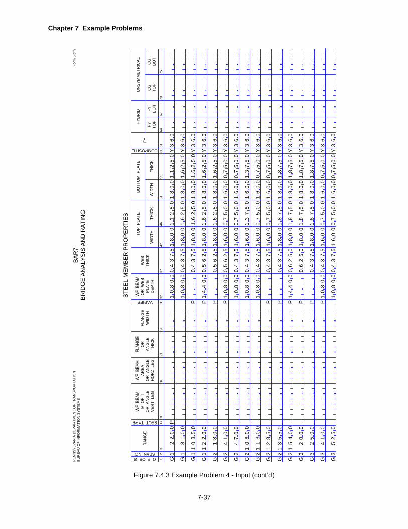
Chapter 7 Example Problems
7-37
Figure 7.4.3 Example Problem 4 - Input (cont’d)
12
STEE
L M
EMBE
R P
RO
PER
TIES
38
WF
BEA
MM
OF
IO
R A
NG
LEVE
RT
LEG
1621
WF
BEA
MAR
EAO
R A
NG
LEH
OR
Z L
EG
26
FLAN
GE
WID
TH
31
FLAN
GE
OR
ANG
LETH
ICK
VARIES
RAN
GE
WF
BEA
MO
R W
EBPL
ATE
DEP
TH
WEB
THIC
KTH
ICK
WID
TH
G F OR SSPAN NO
9
SECT TYPE
3237
4246
THIC
KW
IDTH
5155
60
COMPOSITE 6164
6770
75
TOP
PLA
TEBO
TTO
M P
LATE
FYFY TO
PFY BO
TC
GTO
PC
GBO
T
HYB
RID
UN
SYM
MET
RIC
AL
G1
22
00
P0
00
86
03
Y Y Y
36
0
36
0
G1
G1
50
031
80
0
00
81
65
02
1
G G G G G G G G G G G G
1 2 2 2 2 2 2 2 2 3 3 3
G3
1 12
20
0
18
00
41
00
47
00
00
08
1
00
13
1
50
28
1
50
35
1
00
54
1
20
00
25
00
41
00
50
52
1
00
08
1
P P P P
40
04
1
00
08
1
00
08
1
00
08
1
00
08
1
P P P P P
40
04
1
00
08
1
00
08
1
P
47
53
0
47
53
0
47
53
0
47
53
0
47
53
0
47
53
0
47
53
0
47
53
0
65
02
0
47
53
0
47
53
0
47
53
0
52
56
0
52
56
0
52
56
0
65
02
0
00
81
00
81
00
81
00
81
00
61
00
61
00
61
00
61
00
61
00
81
00
81
00
81
00
61
00
81
00
61
65
02
1
15
02
1
65
02
1
65
02
1
70
05
0
70
05
0
70
05
0
70
05
0
70
05
0
70
05
0
35
07
1
85
07
1
85
07
1
85
07
1
85
07
1
00
81
65
02
1
00
81
00
81
00
81
00
81
00
61
00
61
00
61
00
61
00
61
00
81
00
81
00
81
00
61
00
81
00
61
65
02
1
15
02
1
65
02
1
65
02
1
70
05
0
70
05
0
70
05
0
70
05
0
70
05
0
70
05
0
35
07
1
85
07
1
85
07
1
85
07
1
85
07
1
Y Y Y Y Y Y Y Y Y Y Y Y Y
60
3 36
0
36
0
60
3 36
0
36
0
60
3 36
0
36
0
60
3 36
0
36
0
36
0
BAR
7BR
IDG
E AN
ALYS
IS A
ND
RAT
ING
PEN
NSY
LVAN
IA D
EPAR
TMEN
T O
F TR
ANSP
OR
TATI
ON
BUR
EAU
OF
INFO
RM
ATIO
N S
YSTE
MS
Form
6 o
f 9
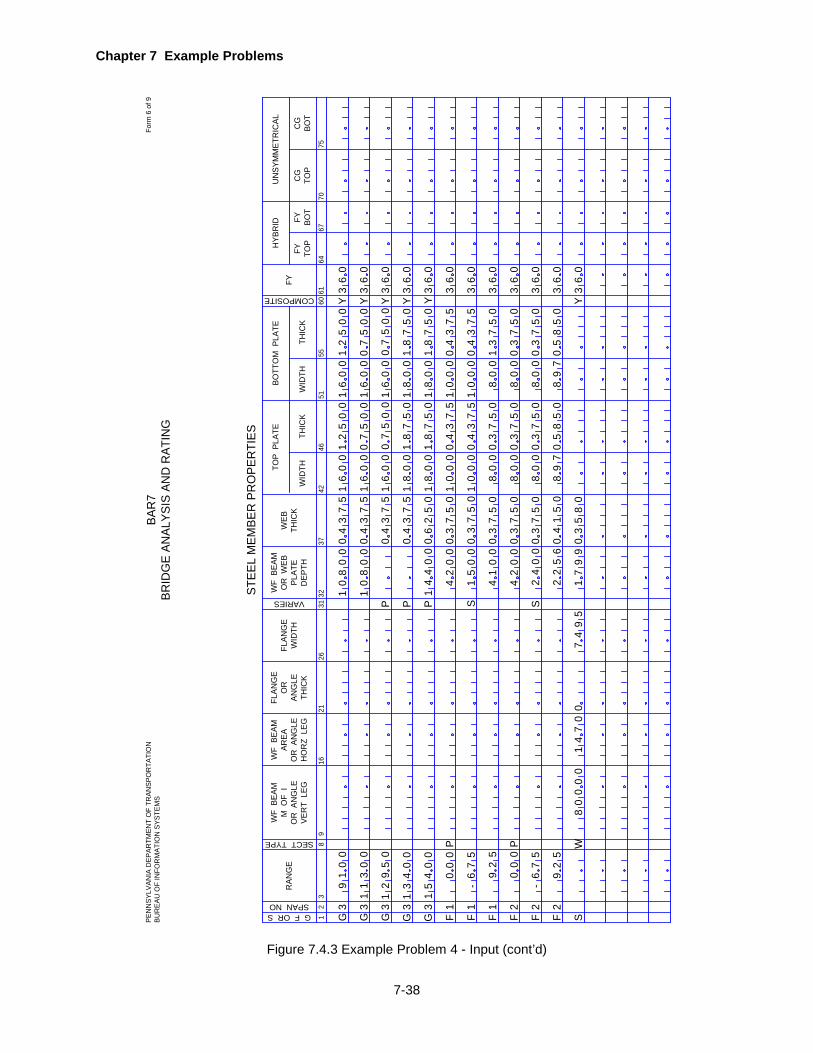
Chapter 7 Example Problems
7-38
Figure 7.4.3 Example Problem 4 - Input (cont’d)
12
STEE
L M
EMBE
R P
RO
PER
TIES
38
WF
BEA
MM
OF
IO
R A
NG
LEVE
RT
LEG
1621
WF
BEA
MAR
EAO
R A
NG
LEH
OR
Z L
EG
26
FLAN
GE
WID
TH
31
FLAN
GE
OR
ANG
LETH
ICK
VARIES
RAN
GE
WF
BEA
MO
R W
EBPL
ATE
DEP
TH
WEB
THIC
KTH
ICK
WID
TH
G F OR SSPAN NO
9
SECT TYPE
3237
4246
THIC
KW
IDTH
5155
60
COMPOSITE 6164
6770
75
TOP
PLA
TEBO
TTO
M P
LATE
FYFY TO
PFY BO
TC
GTO
PC
GBO
T
HYB
RID
UN
SYM
MET
RIC
AL
G3
91
00
P
00
08
60
3Y Y Y
36
0
36
0
G3
G3
50
293
10
0
00
61
70
05
0
G G F F F F F F S
3 3 1 1 1 2 2 2
1 13
40
0
54
00
-
00
0
67
5
25
9
00
0
75
-6
25
9
1
00
08
1
P P P4
00
41
40
02
10
05
40
01
40
02
S
19
97
25
62
0
35
07
0
35
07
0
35
07
0
75
30
38
05
0
47
53
0
47
53
0
47
53
0
47
53
0
65
02
0
35
07
0
00
61
00
61
00
81
00
81
00
8
00
01
00
01
00
8
00
8
97
8
70
05
0
20
05
1
85
07
1
85
07
1
47
53
0
47
53
0
35
07
0
35
07
0
35
07
0
55
08
0
00
61
70
05
0
00
61
00
61
00
81
00
81
00
8
00
01
00
01
00
8
00
8
97
8
70
05
0
20
05
1
85
07
1
85
07
1
47
53
0
47
53
0
35
07
0
35
07
0
35
07
1
55
08
0
Y Y
60
3 36
0
36
0
60
3 36
0
36
0
60
3 36
0
36
0
P W
11
00
00
84
70
17
95
40
S
Y
0
45
01
20
04
BAR
7BR
IDG
E AN
ALYS
IS A
ND
RAT
ING
PEN
NSY
LVAN
IA D
EPAR
TMEN
T O
F TR
ANSP
OR
TATI
ON
BUR
EAU
OF
INFO
RM
ATIO
N S
YSTE
MS
Form
6 o
f 9
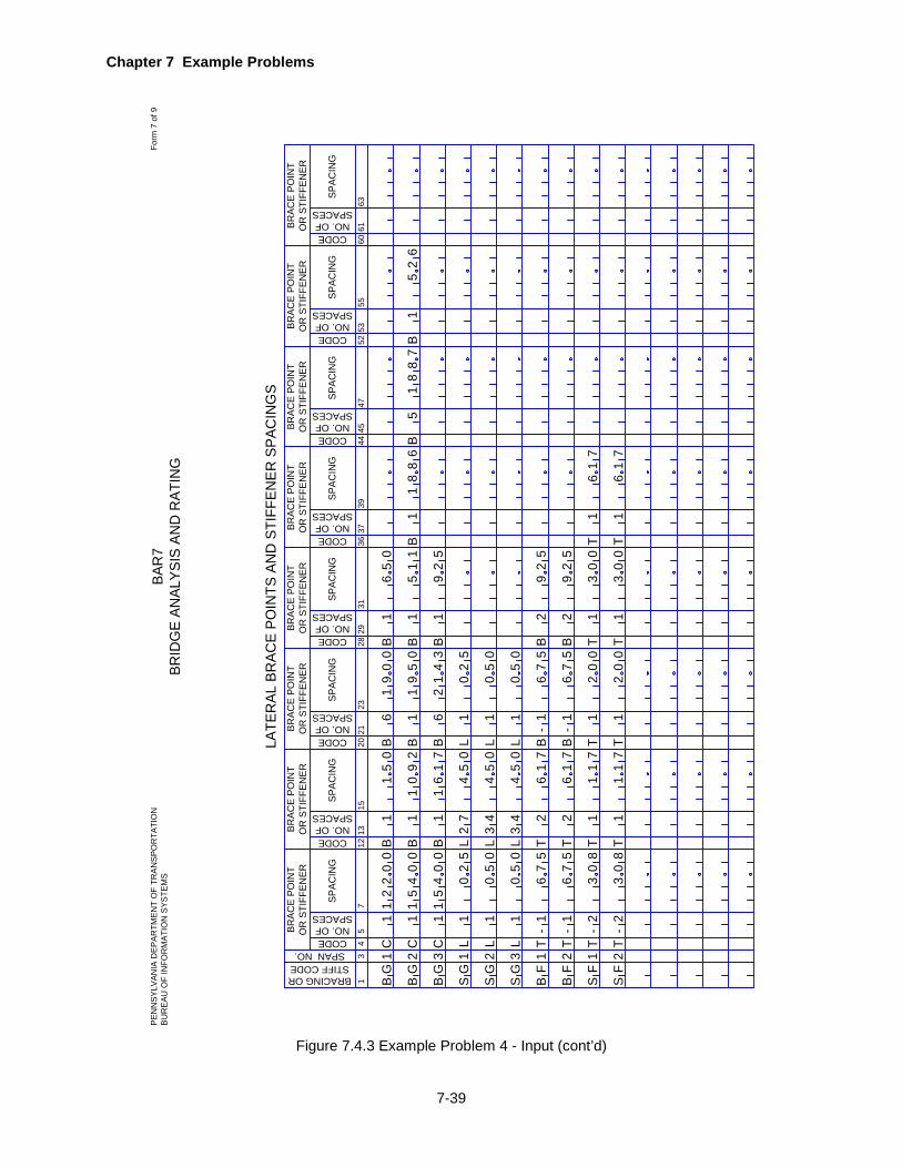
Chapter 7 Example Problems
7-39
Figure 7.4.3 Example Problem 4 - Input (cont’d)
13
LATE
RAL
BR
ACE
POIN
TS A
ND
STI
FFEN
ER S
PAC
ING
S
4
BRAC
E PO
INT
OR
STI
FFEN
ER
75
CODE
SPAC
ING
BRACING ORSTIFF CODESPAN NO.
1215
13CODE
2023
21CODE
2831
29CODENO. OF
SPACES
3639
37CODE
4447
45CODE
5255
53CODE
6063
61CODE
SPAC
ING
SPAC
ING
SPAC
ING
SPAC
ING
SPAC
ING
SPAC
ING
SPAC
ING
BRAC
E PO
INT
OR
STI
FFEN
ERBR
ACE
POIN
TO
R S
TIFF
ENER
BRAC
E PO
INT
OR
STI
FFEN
ERBR
ACE
POIN
TO
R S
TIFF
ENER
BRAC
E PO
INT
OR
STI
FFEN
ERBR
ACE
POIN
TO
R S
TIFF
ENER
BRAC
E PO
INT
OR
STI
FFEN
ER
BG
1C
12
20
0
NO. OFSPACES
NO. OFSPACES
NO. OFSPACES
NO. OFSPACES
NO. OFSPACES
NO. OFSPACES
NO. OFSPACES
BG
BG
SG
SG
SG
BF
BF
SF
SF
1112 2 2 23 3
C C L L L T T T T
1 1 1 1 1 1 1 2 2
-- - -
1
54
00
1
54
00
1
50
2
00
5
00
5
56
7
56
7
83
0
83
0
B B B L L L T T T T
1 1 1
27
34
34 2 2 1 1
50
1
10
92
16
17
45
0
45
0
45
0 76
1
76
1
71
1
71
1
B B B L L L B B T T
1 1 1 1 1 1 11 66
- -
56
7
56
7
02
0
02
0
00
5
00
5
50
2
21
43
19
50
19
00
B B B
1 1 1
65
0
51
1 59
2
59
2
59
2
03
0
03
0
T T
2 2
B B
1 1
T T
1 1
76
1
76
1
B1
18
86
B5
18
87
B1
52
6
BAR
7BR
IDG
E AN
ALYS
IS A
ND
RAT
ING
PEN
NSY
LVAN
IA D
EPAR
TMEN
T O
F TR
ANSP
OR
TATI
ON
BUR
EAU
OF
INFO
RM
ATIO
N S
YSTE
MS
Form
7 o
f 9

Chapter 7 Example Problems
7-40
Figure 7.4.3 Example Problem 4 - Input (cont’d)
12
DIS
TFR
OM
CL
BR
G
SPAN NO
712
14
GIR
DER
FAT
IGU
E D
ETAI
L
1
GR
OSS
VEH
ICLE
WEI
GH
T D
ISTR
IBU
TIO
N
6
MIN
1115
MAX
GR
OSS
VEH
ICLE
WEI
GH
T
1923
2AX
LE
NO
OF
SIN
GLE
UN
IT T
RU
CKS
1
YEAR
BUIL
T
59
1317
ADTT
FATI
GU
E D
ATA
YEAR
OR
GF
YEAR
2529
34
ADTT
2130
NO OFGVWD
YEAR
OR
GF
ADTT
PREV
IOU
S C
OU
NT
REC
ENT
CO
UN
TFU
TUR
E C
OU
NT
R OR N
ON
ELA
NE
DIS
TRFA
CTO
R
DIS
TFR
OM
BOTT
OM
CATEGORY
1921
DIS
TFR
OM
BOTT
OM
CATEGORY26
28
DIS
TFR
OM
BOTT
OM
CATEGORY
33
DIS
TFR
OM
BOTT
OM
CATEGORY
3AX
LE4
AXLE
2731
3AX
LE
NO
OF
SIN
GLE
UN
IT T
RU
CKS
4AX
LE5
OR
>AX
LE
19
66
00
03
10
06
98
99
69
13
78
0N
1 1 1
21
90
12
2
80
84
00
14
62
2
C CEE
12
4
62
4
90
70
1 1 1 1 1 2 2 2 2 2 2 2
1 1 1 1
2 2 2 2 2 4 2 2 2 2
1
1 1 2
62
62
62
62
62
16
3
C C C C C C C C C C C C C
37
37
37
37
7 755
87
37
30
26
10
00
95
00
35
90
60
77
00
74
08
12
20
0
85
01
76
00
69
09
60
00
E6
24
E2
53
2E
00
88
E3
38
8
E6
24
E3
03
29
01
00
C
4E
37
4E
37
E0
03
2
E1
23
2
E4
05
2
E7
53
E7
57
88
01
38
C E1
37
8E
37
22
E2
40
9
E0
06
97
11
64
C
11
16
1C
BAR
7BR
IDG
E AN
ALYS
IS A
ND
RAT
ING
PEN
NSY
LVAN
IA D
EPAR
TMEN
T O
F TR
ANSP
OR
TATI
ON
BUR
EAU
OF
INFO
RM
ATIO
N S
YSTE
MS
Form
8 o
f 9
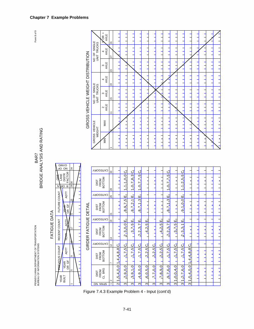
Chapter 7 Example Problems
7-41
Figure 7.4.3 Example Problem 4 - Input (cont’d)
12
DIS
TFR
OM
CL
BR
G
SPAN NO
712
14
GIR
DER
FAT
IGU
E D
ETAI
L
1
GR
OSS
VEH
ICLE
WEI
GH
T D
ISTR
IBU
TIO
N
6
MIN
1115
MAX
GR
OSS
VEH
ICLE
WEI
GH
T
1923
2AX
LE
NO
OF
SIN
GLE
UN
IT T
RU
CKS
1
YEAR
BUIL
T
59
1317
ADTT
FATI
GU
E D
ATA
YEAR
OR
GF
YEAR
2529
34
ADTT
2130
NO OFGVWD
YEAR
OR
GF
ADTT
PREV
IOU
S C
OU
NT
REC
ENT
CO
UN
TFU
TUR
E C
OU
NT
R OR N
ON
ELA
NE
DIS
TRFA
CTO
R
DIS
TFR
OM
BOTT
OM
CATEGORY
1921
DIS
TFR
OM
BOTT
OM
CATEGORY26
28
DIS
TFR
OM
BOTT
OM
CATEGORY
33
DIS
TFR
OM
BOTT
OM
CATEGORY
3AX
LE4
AXLE
2731
3AX
LE
NO
OF
SIN
GLE
UN
IT T
RU
CKS
4AX
LE5
OR
>AX
LE
2 3 3
54
00
88
4
10
93
00
92
75
1
C CE
00
3
3 3 3 3 3 3 3 3
1 1 2 2 2 1 1 1 4
75
75
25
25
25
75
C C C C C C C C C
75
75
88
54
00
27
06
00
04
97
60
78
09
77
00
60
05
49
00
E3
72
E2
54
E1
37
8
E
70
17
5C
E3
7
1 1 1 14
114
2E
75
98
11
10
0C
E7
53
E2
17
8
E1
37
8
E0
01
9
2
25
4 2E
37
2
5
E3
13
2
70
18
3C
70
17
5C
21
15
5C
BAR
7BR
IDG
E AN
ALYS
IS A
ND
RAT
ING
PEN
NSY
LVAN
IA D
EPAR
TMEN
T O
F TR
ANSP
OR
TATI
ON
BUR
EAU
OF
INFO
RM
ATIO
N S
YSTE
MS
Form
8 o
f 9

Chapter 7 Example Problems
7-42
EXAMPLE PROBLEM 5
7.5.1 Problem Description
This is an example of a single span thru truss bridge. The truss has 6 panels and it is symmetric.
The center two panels have counters. The timber deck is supported by stringers. The floorbeams
are attached at the bottom panel points. Figure 7.5.1 on page 7-45 gives details and shows
sketches of the various views of the bridge.
7.5.2 Input
The following input lines are entered. Refer to the completed input data sheets shown in Figure
7.5.3 on page 7-48.
1. Project Identification
• BRIDGE TYPE is "TFS".
• The allowable stress for Safe Load Capacity is 25% higher than the Inventory stress.
• "L" is entered for LANES indicating that the Safe Load Capacity ratings are desired and
the traffic lanes described later are the lanes that are in service.
• Ratings are desired only for the HS20 loading, so a "B" is coded for LIVE LOAD.
• A "0" is coded for OUTPUT so that tables of moments, shears, stresses, deflections, axial
force and ratings will be printed at various sections of a member.
• IMPACT FACTOR should be in accordance with the AASHTO Specifications. This is the
default when this item is left blank.
• The GAGE DISTANCE of 6 feet as specified in the AASHTO Manual is the default when
left blank.
• The PASSING DISTANCE should be 4 feet to give a 2 foot distance from curb to outside
wheel for the single lane as specified in the AASHTO Manual. This is also the default when
left blank.
2. Bridge Cross Section and Loading
• DECK WIDTH, CENTERLINE OF TRUSS TO CURB distance and ROADWAY WIDTH are
taken from the sketches.
• OVERHANG is left blank because the continuity of the floorbeam is not to be considered.
• DISTRIBUTION FACTORS for SHEAR, MOMENT and DEFLECTion are computed
according to AASHTO Specifications as shown in Figure 7.5.2 on page 7-47.
• SLAB THICKness is zero since there is no concrete deck. The weight of the timber deck
will be included under DEAD LOADS.
• DL1 is left blank since the dead loads acting on a truss are entered separately under
TRUSS DEAD LOADS.
• DL2 is the dead load due to the wood deck as computed in Figure 7.5.2 on page 7-47.
Chapter 7 Example Problems
7-43
• F'C and N are left blank because there is no concrete in the superstructure.
• Since the truss is symmetric about the joint at the center of the span, "Y" is entered for
SYMMETRY.
• The live load is to be applied at the lower joints, so "L" is entered for LL.
• The total NO. OF PANELS is 6.
• Truss members have pinned end connections, so "P" is entered for END COND.
• "S" is entered for CORS because the Secant Formula is to be used in determining the
allowable compression in a truss member with end eccentricity.
• For the analysis of this truss, the hinged support (HINGE) is at joint L 0.
• The effect of temperature change is not to be considered for deflection computations, so
TEMP CHANGE is left blank.
• “Y” is entered for gusset plate analysis and rating.
3. Span Lengths
• This is a simple span truss with a span length of 89.1 feet, measured center-to-center of
bearing, as shown in Figure 7.5.1 on page 7-45. The length between abutments (84 feet)
is not the value to be entered here.
• “S” is entered for CONT.
4. Traffic Lanes
• Since "L" is entered for LANES in the PROJECT IDENTIFICATION line, the traffic lanes
that are in service must be described here. There is only one traffic lane occupying the
entire width of the roadway. This lane is at a DIST of 1.5 feet from the left curb and has a
WIDTH of 10 feet. 100 % of the live load is to be applied to this lane (%LL).
5. Stringer Span Lengths
• Since this is a truss type bridge and stringers are to be analyzed as simple spans over
floorbeams, CONT. is equal to "S". Due to symmetry, only the first three STRINGER SPAN
LENGTHS need to be entered in order for the program to rate all floorbeams.
6. Stringer Locations
• Distances of all 8 stringers from the left truss are entered.
7. Truss Geometry
• Since the truss is declared symmetrical only the geometry of panels 1, 2 and 3 should be
described.
• The first PANEL NUMBER is 1, since there is no vertical member L0U0.
• All PANEL WIDTHs are equal to 14.85 feet. A check here shows that the sum of six panel
widths is 89.1 feet, which equals the truss span length entered earlier.
• Y is entered for Y OR N since a vertical is present in each panel.
• The length of the vertical member on the right side of each panel (16.00 feet) is entered for
H1.

Chapter 7 Example Problems
7-44
• The value of H2 is left blank for each panel because there is no joint between the upper
and lower joints.
• The values of H3 are also left blank because the elevation of the lower joint on the right-
hand side of each panel is at the same elevation as the lower joint on the left hand side of
each panel.
• The PANEL TYPE is coded for each panel according to Figure 5.12.2 on page 5-58 in
Chapter 5. Note that panel 3 has counters, which corresponds with PANEL TYPE 13.
8. Truss Dead Loads
• All dead loads acting on the truss were computed from the data available from details
(Refer to Figure 7.5.1 on page 7-45).
9. Truss Member Properties
• All truss member properties were computed from the details given in plans or field notes
(See Figure 7.5.1 on page 7-45). The yield strength of all steel used in this old bridge was
determined to be 26 ksi.
• Also note that areas or moments of inertia for some members are less than would be
calculated from the plans. Engineering judgment must be used to enter these values so
that they reflect the actual deteriorated state of the materials in the field. For example,
members L0L1, L1L2 and L2L3 are shown on the sketches to be the same (Two 2" X 3/4"
Bars). During inspection of this structure, it was discovered that in both the second and
third panels, only one of the bars was acting to support the structure. This is reflected in
the coding of the properties for members L1L2 and L2L3.
10. Steel Beam Properties
• All Member properties for floorbeams 1 (under joint 2), 2 and 3 and an I-beam stringer were
obtained from plans. Here again, engineering judgment was used to code these values to
reflect the deteriorated state of materials.
11. Gusset Plate Properties
• All gusset plate properties left to the point of symmetry were entered to show the gusset
plate calculations. Please note that these are fake numbers which may not reflect the actual
information in the plan.
• This is a double-sided gusset plate connection and the thickness of gusset plate at each
side is 0.625 in. Fy is 33 ksi and Fu is 50 ksi.
• The shear capacity of all fasteners at the operating level is 35 ksi and the diameter of all
fasteners is 1 in.
12. Gusset Plate Member Properties
• All gusset plate member properties left to the point of symmetry were entered to show the
gusset plate calculations for each truss member. Please note that these are fake numbers
which may not reflect the actual information in the plan.
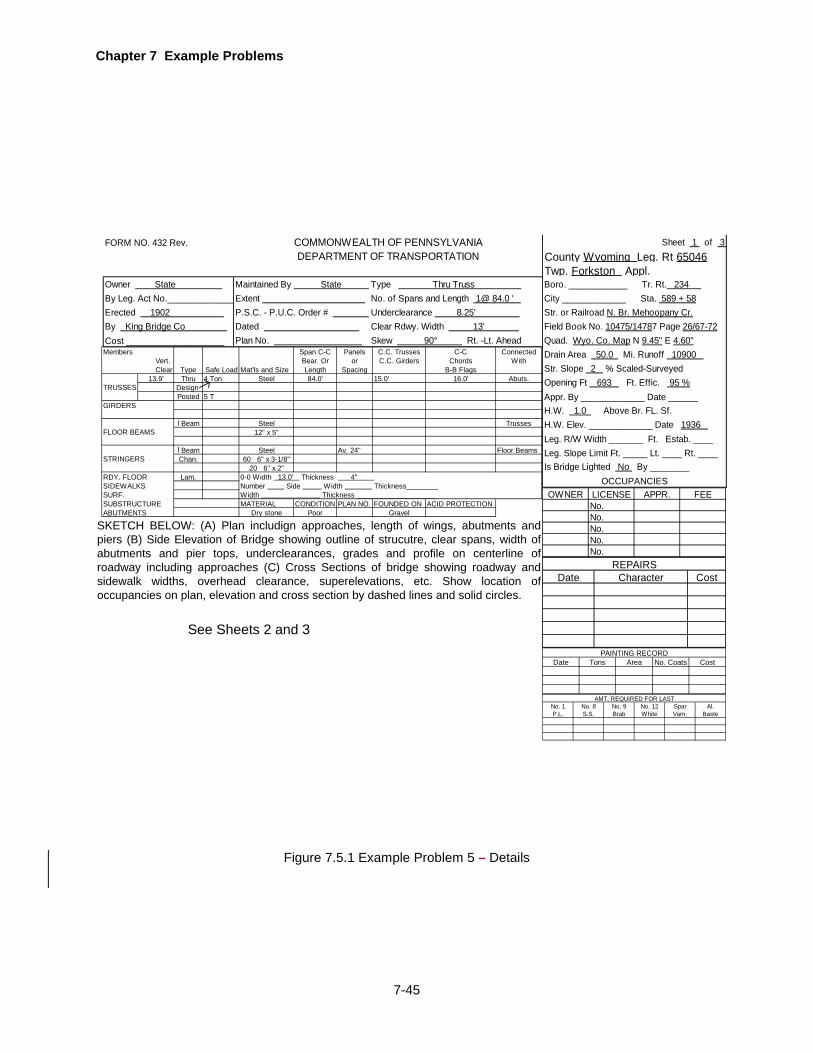
Chapter 7 Example Problems
7-45
Figure 7.5.1 Example Problem 5 – Details
FORM NO. 432 Rev. Sheet 1 of 3 County Wyoming Leg. Rt 65046Twp. Forkston Appl. _________no
Owner State Maintained By State Type Thru Truss Boro. ____________No Tr. Rt. 234 By Leg. Act No.______________ Extent NNo. of Spans and Length 1@ 84.0 ' City _____________ no Sta. 589 + 58Erected 1902 P.S.C. - P.U.C. Order # Underclearance 8.25' Str. or Railroad N. Br. Mehoopany Cr.By King Bridge Co Dated NoClear Rdwy. Width 13' Field Book No. 10475/14787 Page 26/67-72Cost ____________________ Plan No. NSkew 90° Rt. -Lt. Ahead Quad. Wyo. Co. Map N 9.45" E 4.60"
Drain Area 50.0 Mi. Runoff 10900 Str. Slope 2 % Scaled-SurveyedOpening Ft 693 Ft. Effic. 95 %Appr. By _____________ Date ______H.W. 1.0 Above Br. FL. Sf.H.W. Elev. _____________ Date 1936 Leg. R/W Width _______ Ft. Estab. ____Leg. Slope Limit Ft. _____ Lt. ____ Rt. ____Is Bridge Lighted No By ________
OCCUPANCIES
COMMONWEALTH OF PENNSYLVANIADEPARTMENT OF TRANSPORTATION
Span C-C Panels C.C. Trusses C-C ConnectedBear. Or or C.C. Girders Chords WithLength Spacing B-B Flags
13.9' Thru 4 Ton Steel 84.0' 15.0' 16.0' Abuts.Design Posted 5 T
I Beam Steel Trusses12" x 5"
I Beam Steel Av. 24" Floor BeamsChan. 60 6" x 3-1/8"
20 6" x 2"Lam.
MATERIAL CONDITION PLAN NO. FOUNDED ON ACID PROTECTIONDry stone Poor Gravel
0-0 Width 13.0' Thickness 4" Number Side Width Thickness________
ABUTMENTS
Type Safe Load Mat'ls and Size
Width Thickness ____________________
RDY. FLOORSIDEWALKSSURF.SUBSTRUCTURE
TRUSSES
GIRDERS
FLOOR BEAMS
STRINGERS
MembersVert. Clear
OWNER LICENSE APPR. FEENo.No.No.No.No.
Date Character CostREPAIRS
Date Tons Area No. Coats CostPAINTING RECORD
SKETCH BELOW: (A) Plan includign approaches, length of wings, abutments and piers (B) Side Elevation of Bridge showing outline of strucutre, clear spans, width of abutments and pier tops, underclearances, grades and profile on centerline of roadway including approaches (C) Cross Sections of bridge showing roadway and sidewalk widths, overhead clearance, superelevations, etc. Show location of occupancies on plan, elevation and cross section by dashed lines and solid circles.
See Sheets 2 and 3
No. 1 No. 8 No. 9 No. 12 Spar Al.P.L. S.S. Brab White Varn. Baste
AMT. REQUIRED FOR LAST
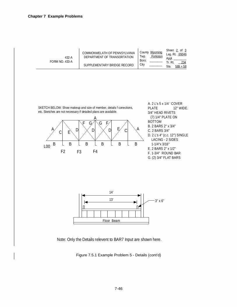
Chapter 7 Example Problems
7-46
Sheet 2 of 3 Leg. Rt. 65046Appl. ________Tr. Rt. 234Sta. 589 + 58
3" x 6"
Floor Beam
13'
14'
A
SKETCH BELOW: Show makeup and size of member, details f conections, etc. Sketches are not necessary if detailed plans are available.
B
C
B B B B B
E DF
AG
DG F
D E C A
A. 2 L's 5 x 1/4 ' COVER PLATE 12" WIDE. 3/4" HEAD RIVETS (7) 1/4" PLATE ON BOTTOMB. 2 BARS 2" x 3/4"C. 2 BARS 3/4"D. 2 L's 4" (c.c. 12") SINGLE LACING - 2 SIDES 1-1/4"x 3/16"E. 2 BARS 2" x 1/2"F. 1-3/4" ROUND BARG. (2) 3/4" FLAT BARS
432-AFORM NO. 433-A
COMMONWELATH OF PENNSYLVANIADEPARTMENT OF TRANSORTATION
SUPPLEMENTARY BRIDGE RECORD
County WyomingTwp. ForkstonBoro. ________ City ________
Note: Only the Details relevent to BAR7 Input are shown here.
F2 F3 F4L00
Figure 7.5.1 Example Problem 5 - Details (cont’d)
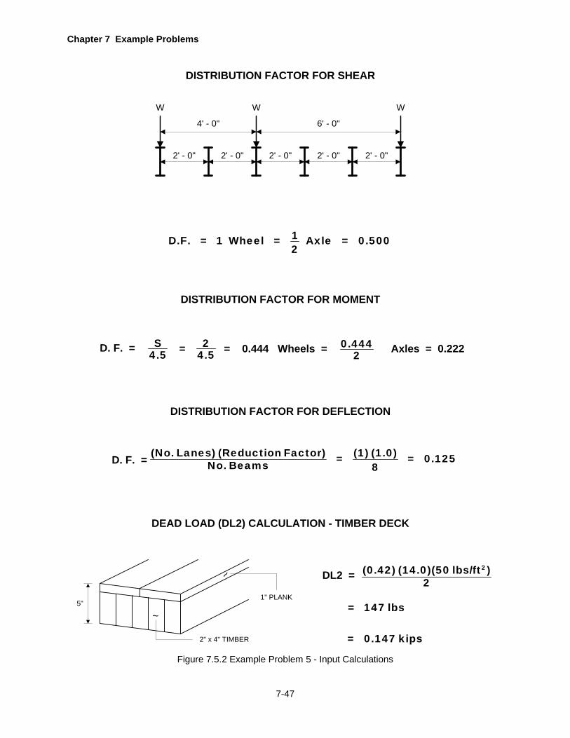
Chapter 7 Example Problems
7-47
Figure 7.5.2 Example Problem 5 - Input Calculations
DISTRIBUTION FACTOR FOR SHEAR
4' - 0"
2' - 0"
6' - 0"
W W
DISTRIBUTION FACTOR FOR MOMENT
D. F. = S4.5 Wheels = 0.444
2 Axles = 0.222= 24.5
DISTRIBUTION FACTOR FOR DEFLECTION
D. F. = (No. Lanes) (Reduction Factor) (1) (1.0)= = 0.125No. Beams 8
1D.F. = 1 Wheel = Axle = 0.5002
2' - 0" 2' - 0"
W
2' - 0" 2' - 0"
= 0.444
DEAD LOAD (DL2) CALCULATION - TIMBER DECK
1" PLANK
~
~
2" x 4" TIMBER
5"
DL2 = 2(0.42) (14.0)(50 lbs/ft )
2
= 147 lbs
= 0.147 kips
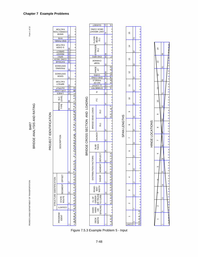
Chapter 7 Example Problems
7-48
COUNTY
17
PRO
GR
AMID
ENT
STR
UC
TUR
E ID
ENTI
FIC
ATIO
N
STAT
ER
OU
TED
ESC
RIP
TIO
N
4548
5154
5760
67
BRID
GE
TYPE
913
1721
SEG
MEN
TO
FFSE
T
IMPACTFACTOR
GAGEDISTANCE
PASSINGDISTANCE
63
PRO
JEC
T ID
ENTI
FIC
ATIO
N
15
DEC
KW
IDTH
DIS
TRIB
UTI
ON
FAC
TOR
S
MO
MEN
T
4751
5362
70
UNIT WEIGHT DECK CONC
913
1721
DEF
LEC
T
6674
BRID
GE
CR
OSS
SEC
TIO
N A
ND
LO
ADIN
G
SHEA
R
2529
3342
DL1
F'C
12
19
CONT
712
1722
3
SPAN
LEN
GTH
S
24
2732
3742
67
85
SLC
LEVE
L
5253
LANESLIVE LOADOUTPUT
FATIGUE 6465
66
CONC DECKSPEC
REDISTDIRECT 68
S OVERFACTOR
OVE
R-
HAN
GO
RSP
ACIN
G
CL
OF
GIR
DER
OR
TR
USS
TO C
UR
B
RO
AD-
WAY
WID
TH
SLAB
THIC
KH
AUN
CH
37
DL2
BRID
GE
DEA
D L
OAD
S
N
SYMMETRYLL LOCAT
NO OFPANELS
END COND
5455
5758
59CORS
HIN
GE
AT
TEMPCHANGE
65
STR
ING
ERD
L1
FLO
OR
-BE
AMD
L1
4752
5762
6772
1011
1213
1415
1
19
611
1621
3
HIN
GE
LOC
ATIO
NS
24
2631
3641
67
85
4651
5661
66
1011
1213
14
END BRG
=B
RR
AT
PEN
NSY
LVAN
IA D
EPAR
TMEN
T O
F TR
ANSP
OR
TATI
ON
Form
1 o
f 10
BAR
7BR
IDG
E AN
ALYS
IS A
ND
RAT
ING
71
END PANEL 72
HYB
65
65
04
01
04
06
05
TR
US
S-
FL
OO
RB
EA
M-
ST
RI
NG
ER
TF
SI
25
LB
0
14
00
10
01
30
00
50
00
22
20
12
50
14
7L
Y6
PS
L0
L
89
10
73
SKEW CORRECTION
FACTOR
GUSSET Y77
00
00
S0
Figure 7.5.3 Example Problem 5 - Input
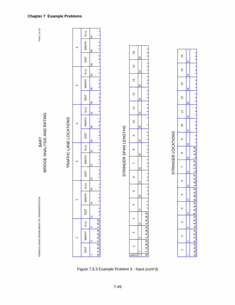
Chapter 7 Example Problems
7-49
19
TRA
FFIC
LA
NE
LO
CA
TIO
NS
12
111
CONT
610
1418
3
STR
ING
ER
SP
AN
LE
NG
THS
24
2630
3442
65
4650
5458
1213
14
1
111
59
1317
3
STR
ING
ER
LO
CA
TIO
NS
24
2129
3741
78
96
4549
5357
1213
1415
5
1
DIS
TW
IDTH
% L
L
1220
16
2
DIS
TW
IDTH
% L
L
2331
27
3
DIS
TW
IDTH
% L
L
3442
38
4
DIS
TW
IDTH
% L
L
4553
49
5
DIS
TW
IDTH
% L
L
5664
60
6
DIS
TW
IDTH
% L
L
22
78
9
38
1015
5
2533
10
BA
R7
BR
IDG
E A
NA
LYS
IS A
ND
RA
TIN
GP
EN
NS
YLV
AN
IA D
EP
AR
TME
NT
OF
TRA
NS
PO
RTA
TIO
NFo
rm 2
of 1
0
50
10
01
00
01
S1
54
81
54
81
54
8
05
05
02
45
05
60
58
05
00
21
15
05
40
1
0
00
00
0
Figure 7.5.3 Example Problem 5 - Input (cont’d)

Chapter 7 Example Problems
7-50
13PA
NEL
W
IDTH
PANELNUMBER
712
16
Y OR N
TRU
SS G
EOM
ETR
Y
H3
218
H1
H2
VER
TIC
AL P
OST
PANELTYPE
12P
P
TRU
SS D
EAD
LO
ADS
4
U LLOC
ATC
ON
CLO
AD
910P
P
12
U LLOC
ATC
ON
CLO
AD
1718P
P
20
U LLOC
ATC
ON
CLO
AD
2526P
P
28
U LLOC
ATC
ON
CLO
AD
BAR
7BR
IDG
E AN
ALYS
IS A
ND
RAT
ING
PEN
NSY
LVAN
IA D
EPAR
TMEN
T O
F TR
ANSP
OR
TATI
ON
Form
4 o
f 10
11
41
Y1
85
00
6
14
Y1
85
00
6
14
Y1
85
00
6
2 336
1
1U L
1
10
7
32
5
U L
2 2
U L
06
5
330
65
32
53
25
L1
53
0
Figure 7.5.3 Example Problem 5 - Input (cont’d)
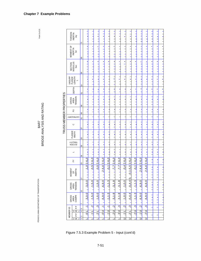
Chapter 7 Example Problems
7-51
TRU
SS M
EMBE
R P
RO
PER
TIES
BAR
7BR
IDG
E AN
ALYS
IS A
ND
RAT
ING
PEN
NSY
LVAN
IA D
EPAR
TMEN
T O
F TR
ANSP
OR
TATI
ON
Form
5 o
f 10
12P
P
4
U M LMEM
BER
ID
712
GR
OSS
AREA
CO
MPR
1723
MO
MEN
TO
FIN
ERTI
A
26
L
30
FY
ECCENTRICITY
5
U M LP
P
GR
OSS
AREA
TEN
SIO
N
FLAN
GE
WID
THC
CATEGORY
GR
OSS
AREA
TEN
SIO
NFU
3337
4143
46
L1
L0
L0
L2
L1
L1
L3
L2 1
U
1U
30
0
15
0
15
0
69
0
11
3
30
01
02 2 2 2 2
01
05
26
6
05
50
50
90
13
1 1 6 1
60
60
60
60
60
L3
L2 1 2 2
LUU
2U
3U L
3
L2 3
U
31
8
31
8
10
0
04
4
11
3
2 2 2 2 2
77
77
04
15
50
0
01
31
8
31
8
10
0
04
4
11
3
60
60
60
60
60
26
0
26
0
26
6
26
6
69
0
69
0
1 2UU
2U
3U
69
0
69
0
SEC
TIO
N
MO
DU
LUS
Sxc
MO
MEN
T O
F IN
ERTI
AIy
c
TOR
SIO
NIN
ERTI
AJx
y
5154
65
DEP
TH
71
UN
SUPP
FLAN
GE
LEN
GTH
L
59
Figure 7.5.3 Example Problem 5 - Input (cont’d)
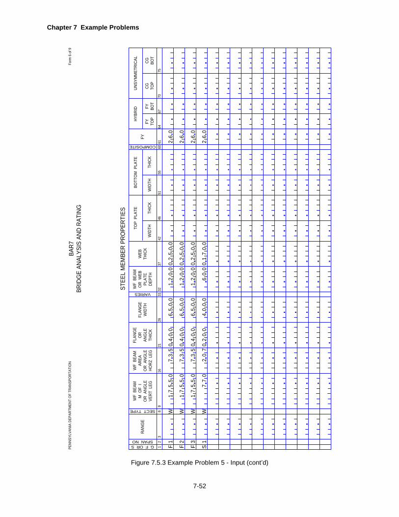
Chapter 7 Example Problems
7-52
12
STEE
L M
EMBE
R PR
OPE
RTIE
S
38
WF
BEA
MM
OF
IO
R A
NGLE
VERT
LEG
1621
WF
BEA
MAR
EAO
R A
NGLE
HORZ
LEG
26
FLAN
GE
WID
TH
31
FLAN
GE
OR
ANG
LETH
ICK
VARIES
RANG
E
WF
BEA
MO
R W
EBPL
ATE
DEPT
H
WEB
THIC
KTH
ICK
WID
TH
G F OR SSPAN NO
9
SECT TYPE
3237
4246
THIC
KW
IDTH
5155
60
COMPOSITE 6164
6770
75
TOP
PLA
TEBO
TTO
M P
LATE
FYFY TO
PFY BO
TCG TO
PCG BO
T
HYBR
IDUN
SYM
MET
RICA
L
BAR7
BRID
GE
ANAL
YSIS
AND
RAT
ING
PENN
SYLV
ANIA
DEP
ARTM
ENT
OF
TRAN
SPO
RTAT
ION
Form
6 o
f 9
F1
F2
F3
S1
W7
1
W W W
71
71
55
0
55
0
55
0
77
0
73
5
73
5
73
5
20
7
0
240
0
04
00
04
00
00
0
10
02
00
0 0
20
10
65
00
65
00
65
00
40
00
12
00
12
00
6
2 2
00
5
00
7
00
5
00
5
60
2 26
0
26
0
60
2
Figure 7.5.3 Example Problem 5 - Input (cont’d)

Chapter 7 Example Problems
7-53
Figure 7.5.3 Example Problem 5 - Input (cont’d)
13
LATE
RAL
BR
ACE
POIN
TS A
ND
STI
FFEN
ER S
PAC
ING
S
4
BRAC
E PO
INT
OR
STI
FFEN
ER
75
CODE
SPAC
ING
BRACING ORSTIFF CODESPAN NO.
1215
13CODE20
2321CODE
2831
29CODENO. OF
SPACES
3639
37CODE
4447
45CODE
5255
53CODE
6063
61CODE
SPAC
ING
SPAC
ING
SPAC
ING
SPAC
ING
SPAC
ING
SPAC
ING
SPAC
ING
BRAC
E PO
INT
OR
STI
FFEN
ERBR
ACE
POIN
TO
R S
TIFF
ENER
BRAC
E PO
INT
OR
STI
FFEN
ERBR
ACE
POIN
TO
R S
TIFF
ENER
BRAC
E PO
INT
OR
STI
FFEN
ERBR
ACE
POIN
TO
R S
TIFF
ENER
BRAC
E PO
INT
OR
STI
FFEN
ER
NO. OFSPACES
NO. OFSPACES
NO. OFSPACES
NO. OFSPACES
NO. OFSPACES
NO. OFSPACES
NO. OFSPACES
BAR
7BR
IDG
E AN
ALYS
IS A
ND
RAT
ING
PEN
NSY
LVAN
IA D
EPAR
TMEN
T O
F TR
ANSP
OR
TATI
ON
BUR
EAU
OF
INFO
RM
ATIO
N S
YSTE
MS
Form
7 o
f 9
BF
BF
BF
1 2 3
T T T
1 1 1
00
5
00
5
00
5
T T T
4 4 4
20
0
20
0
20
0

Chapter 7 Example Problems
7-54
GU
SSET
PLA
TE P
RO
PER
TIES
GU
SSET
PLA
TE M
EMBE
R P
RO
PER
TIES
PEN
NSY
LVAN
IA D
EPAR
TMEN
T O
F TR
ANSP
OR
TATI
ON
Form
10
of 1
0BA
R7
BRID
GE
ANAL
YSIS
AN
D R
ATIN
G
LOC11
4
GU
S C
ARD
YIEL
D
STR
ESS
Fy
4349
615
1115
19
TEN
SILE
ST
RES
SFu
THIC
K
MAX
U
NSU
PPO
RTE
D
EDG
EB
SHEA
R
CAP
ACIT
YO
FFA
STEN
ER
5566FA
STEN
ERD
IAM
ETER
GU
S
LOC2
7
LEN
GTH
Ha
LEN
GTH
Hb
LEN
GTH
Hc
ECC
ENTR
ICIT
YEa
ECC
ENTR
ICIT
YEb
ECC
ENTR
ICIT
YEc
2531
37
SU
GS
UG
SU
G
69
SSS
UUU
GGG
33
1GAM
C
ARD
TRU
SS M
EMBE
R
694
519
21
NT
2331
DIS
TAN
CE
WD
ISTA
NC
EL
GM
B
LOC1
LOC2
8
NL
LEN
GTH
Lc
NO 713
4345
NT
47
DIS
TAN
CE
WD
ISTA
NC
EL
32
NL
LEN
GTH
Lc
37
NO
5561
76
NT
67
DIS
TAN
CE
WD
ISTA
NC
EL
NL
52
NO
LEN
GTH
Lc
TRU
SS M
EMBE
RTR
USS
MEM
BER
G GGB BB
MMM
NTT
2871
NTT
NTT
5678
MMBB
G G
BBBBBB
MMMMMM
GGGGG G
10
ULLLL0
0 132
UU0
32
0 0 0 0
0
2
0000L LL
05
03
3 33
3333 3
3 33
5555
0000 0
00000
6
00
55
26 6
25 5
66664
13 3
10
552
333331 1 111
2222
555
44
044444
4 4 4444
000
0 0 0
0000
57 77
7777
7 777
77 7 7
7777
7
7
0 0 0 0
555555
5555
5 5 5555
55 55
03
53
1
333
0 000001 1 1111
33
3333 333
5 55 5 55
0 0 0 0 0 00
00 0 0 0 0 0
0 0 0
0 0 0 0 0 000 0
00
0
0 0 0
0
0 0
0
0 0 0 0 0 0 0
0 0 0 0
0000000 0 0
0 0 0 00
0 0 00 0 00
02
UUULLL
0000
12 3 100
3321 2 3
1 1
1 10
16
50
1
414
0
UUU151 415
01 2
10
05
60
31
01
11
10
500 0 5 0060 0
161616166
0 5
4
0 555 5 0
4
10
10
20
20
0
21
0
0000000
22021
00001 2 1
021
0
20
3 1 3 1 3 11333
000000000
001111
1 11
1111
1
340
30
220
0
2 222 2
0002
111
0000 0 0
11
11 1
1
1 10
10
11
00
1
0
55
3 33
0000
34
6 65
44
0
0033
00
33
30
50
63
0
2 5232 122
0 0
000
0
00
00
61
011
0
000 000
120
2
02
1
501
1
11
1
005 611
111
0
1000
3344
000
000
3333 33
666
555
444
332
000 00
009
0 00 052
20 0
10 0
2 11
0 5
0
51
1 63
11
0
0 0 0 0 0 0
0 0
000
0
000 0
0 0 0 00 00 0000 0
0 0 0 0
0 00 0 0 0 0 0 000
0 0 0 0 00 0 0000 0
50
01
10
05
64
00
3
00
00 0
0 00
000
0 00
Figure 7.5.3 Example Problem 5 - Input (cont’d)
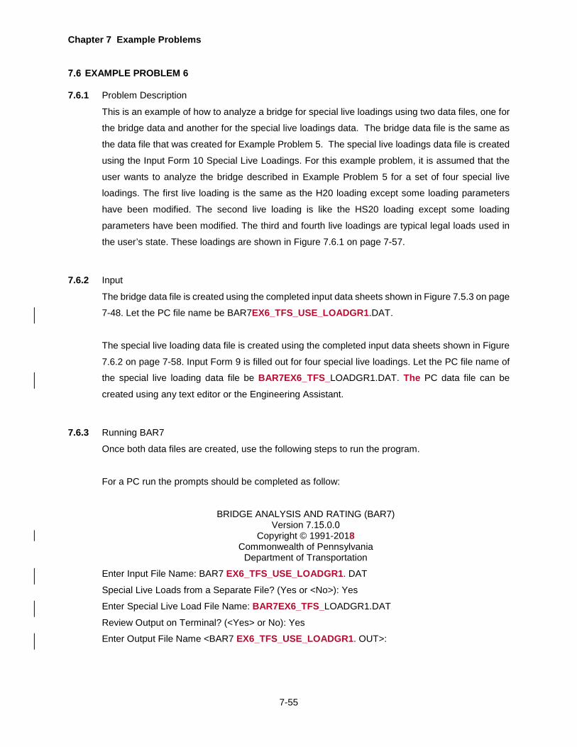
Chapter 7 Example Problems
7-55
EXAMPLE PROBLEM 6
7.6.1 Problem Description
This is an example of how to analyze a bridge for special live loadings using two data files, one for
the bridge data and another for the special live loadings data. The bridge data file is the same as
the data file that was created for Example Problem 5. The special live loadings data file is created
using the Input Form 10 Special Live Loadings. For this example problem, it is assumed that the
user wants to analyze the bridge described in Example Problem 5 for a set of four special live
loadings. The first live loading is the same as the H20 loading except some loading parameters
have been modified. The second live loading is like the HS20 loading except some loading
parameters have been modified. The third and fourth live loadings are typical legal loads used in
the user’s state. These loadings are shown in Figure 7.6.1 on page 7-57.
7.6.2 Input
The bridge data file is created using the completed input data sheets shown in Figure 7.5.3 on page
7-48. Let the PC file name be BAR7EX6_TFS_USE_LOADGR1.DAT.
The special live loading data file is created using the completed input data sheets shown in Figure
7.6.2 on page 7-58. Input Form 9 is filled out for four special live loadings. Let the PC file name of
the special live loading data file be BAR7EX6_TFS_LOADGR1.DAT. The PC data file can be
created using any text editor or the Engineering Assistant.
7.6.3 Running BAR7
Once both data files are created, use the following steps to run the program.
For a PC run the prompts should be completed as follow:
BRIDGE ANALYSIS AND RATING (BAR7) Version 7.15.0.0
Copyright © 1991-2018 Commonwealth of Pennsylvania
Department of Transportation
Enter Input File Name: BAR7 EX6_TFS_USE_LOADGR1. DAT
Special Live Loads from a Separate File? (Yes or <No>): Yes
Enter Special Live Load File Name: BAR7EX6_TFS_LOADGR1.DAT
Review Output on Terminal? (<Yes> or No): Yes
Enter Output File Name <BAR7 EX6_TFS_USE_LOADGR1. OUT>:

Chapter 7 Example Problems
7-56
Alternately, a PC run can be made by using the following command at the DOS prompt.
A: BAR7 BAR7EX5.DAT BAR7EX5.OUT LOADGR1.DAT
Where BAR7 is the executable file, BAR7 EX6_TFS_USE_LOADGR1.DAT is the bridge data input
file, BAR7 EX6_TFS_USE_LOADGR1.OUT is the output file and BAR7EX6_TFS_LOADGR1.DAT
is the special live loading data file. In the above command, each of the files can be specified by
giving the full directory path.
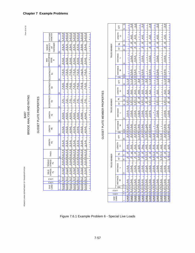
Chapter 7 Example Problems
7-57
GUS
SET
PLAT
E PR
OPE
RTIE
S
GUS
SET
PLAT
E M
EMBE
R PR
OPE
RTIE
S
PENN
SYLV
ANIA
DEP
ARTM
ENT
OF
TRAN
SPO
RTAT
ION
Form
10
of 1
0BA
R7BR
IDG
E AN
ALYS
IS A
ND R
ATIN
G
LOC1
14
GUS
CA
RD
YIEL
D ST
RESS
Fy
4349
615
1115
19
TENS
ILE
STRE
SSFu
THIC
K
MAX
UN
SUPP
ORT
ED
EDG
EB
SHEA
R CA
PACI
TYO
FFA
STEN
ER
5566FA
STEN
ERDI
AMET
ER
GU
S
LOC2
7
LENG
THHa
LENG
THHb
LENG
THHc
ECCE
NTRI
CITY
EaEC
CENT
RICI
TYEb
ECCE
NTRI
CITY
Ec
2531
37
SU
GS
UG
SU
G
69
SSS
UUU
GGG
33
1GAM
CA
RD
TRUS
S M
EMBE
R
694
519
21
NT
2331
DIST
ANCE
WDI
STAN
CEL
GM
B
LOC1
LOC2
8
NLLE
NGTH
Lc
NO 713
4345
NT
47
DIST
ANCE
WDI
STAN
CEL
32
NLLE
NGTH
Lc
37
NO
5561
76
NT 67
DIST
ANCE
WDI
STAN
CEL
NL
52
NO
LENG
THLc
TRUS
S M
EMBE
RTR
USS
MEM
BER
G GGB BB
MMM
NTT
2871
NTT
NTT
5678
MMBB
G G
BBBBBB
MMMMMM
GGGGG G
10
ULLLL0
0 132
UU0
32
0 0 0 0
0
2
0000L LL
05
03
3 33
3333 3
3 33
5555
0000 0
00000
6
00
55
26 6
25 5
66664
13 3
10
552
333331 1 111
2222
555
44
044444
4 4 4444
000
0 0 0
0000
57 77
7777
7 777
77 7 7
7777
7
7
0 0 0 0
555555
5555
5 5 5555
55 55
03
53
1
333
0 000001 1 1111
33
3333 333
5 55 5 55
0 0 0 0 0 00
00 0 0 0 0 0
0 0 0
0 0 0 0 0 000 0
00
0
0 0 0
0
0 0
0
0 0 0 0 0 0 0
0 0 0 0
0000000 0 0
0 0 0 00
0 0 00 0 00
02
UUULLL
0000
12 3 100
3321 2 3
1 1
1 10
16
50
1
414
0
UUU151 415
01 2
10
05
60
31
01
11
10
500 0 5 0060 0
161616166
0 5
4
0 555 5 0
4
10
10
20
20
0
21
0
0000000
22021
00001 2 1
021
0
20
3 1 3 1 3 11333
000000000
001111
1 11
1111
1
340
30
220
0
2 222 2
0002
111
0000 0 0
11
11 1
1
1 10
10
11
00
1
0
55
3 33
0000
34
6 65
44
0
0033
00
33
30
50
63
0
2 5232 122
0 0
000
0
00
00
61
011
0
000 000
120
2
02
1
501
1
11
1
005 611
111
0
1000
3344
000
000
3333 33
666
555
444
332
000 00
009
0 00 052
20 0
10 0
2 11
0 5
0
51
1 63
11
0
0 0 0 0 0 0
0 0
000
0
000 0
0 0 0 00 00 0000 0
0 0 0 0
0 00 0 0 0 0 0 000
0 0 0 0 00 0 0000 0
50
01
10
05
64
00
3
00
00 0
0 00
000
0 00
Figure 7.6.1 Example Problem 6 - Special Live Loads
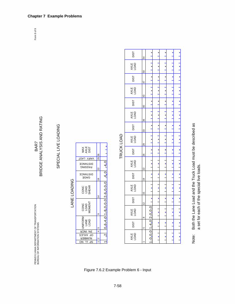
Chapter 7 Example Problems
7-58
12
SP LL NO
45
914
CO
NC
LOAD
MO
MEN
T
LAN
E LO
ADIN
G
UN
IFO
RM
LAN
ELO
AD
2226
19
GAGEDISTANCE
NUMBEROF AXLES3% INCR
CO
NC
LOAD
SHEA
R
PASSINGDISTANCE
25
VARY LAST
MAX
AXLE
DIS
T
1
TRU
CK
LOAD
8
AXLE
LOAD
5DIS
TAX
LELO
AD
12
DIS
TAX
LELO
AD
15
DIS
TAX
LELO
AD
19
DIS
TAX
LELO
AD
22
DIS
TAX
LELO
AD
40
DIS
TAX
LELO
AD
47
DIS
TAX
LELO
AD
54
DIS
T
SPEC
IAL
LIVE
LO
ADIN
G
Not
e:
Both
the
Lane
Loa
d an
d th
e Tr
uck
Load
mus
t be
desc
ribed
as
a se
t for
eac
h of
the
spec
ial l
ive
load
s.
2629
3336
4350
BAR
7BR
IDG
E AN
ALYS
IS A
ND
RAT
ING
PEN
NSY
LVAN
IA D
EPAR
TMEN
T O
F TR
ANSP
OR
TATI
ON
BUR
EAU
OF
INFO
RM
ATIO
N S
YSTE
MS
Form
9 o
f 9
12
00
00
00
00
18
26
06
04
00
00
14
00
02
46
1
Figure 7.6.2 Example Problem 6 - Input
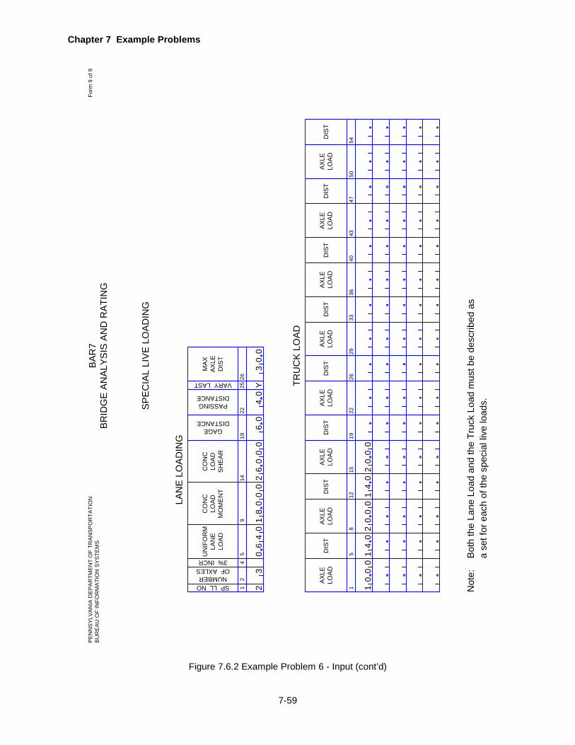
Chapter 7 Example Problems
7-59
Figure 7.6.2 Example Problem 6 - Input (cont’d)
12
SP LL NO
45
914
CO
NC
LOA
DM
OM
EN
T
LAN
E L
OA
DIN
G
UN
IFO
RM
LAN
ELO
AD
2226
19
GAGEDISTANCE
NUMBEROF AXLES3% INCR
CO
NC
LOA
DS
HE
AR
PASSINGDISTANCE
25
VARY LAST
MA
XA
XLE
DIS
T
1
TRU
CK
LO
AD
8
AX
LELO
AD
5DIS
TA
XLE
LOA
D
12
DIS
TA
XLE
LOA
D
15
DIS
TA
XLE
LOA
D
19
DIS
TA
XLE
LOA
D
22
DIS
TA
XLE
LOA
D
40
DIS
TA
XLE
LOA
D
47
DIS
TA
XLE
LOA
D
54
DIS
T
SP
EC
IAL
LIV
E L
OA
DIN
G
Not
e:
Bot
h th
e La
ne L
oad
and
the
Truc
k Lo
ad m
ust b
e de
scrib
ed a
sa
set f
or e
ach
of th
e sp
ecia
l liv
e lo
ads.
2629
3336
4350
BA
R7
BR
IDG
E A
NA
LYS
IS A
ND
RA
TIN
GP
EN
NS
YLV
AN
IA D
EP
AR
TME
NT
OF
TRA
NS
PO
RTA
TIO
NB
UR
EA
U O
F IN
FOR
MA
TIO
N S
YS
TEM
SFo
rm 9
of 9
30
00
00
00
01
82
60
60
42
64
Y3
00
00
00
14
00
02
10
14
00
02
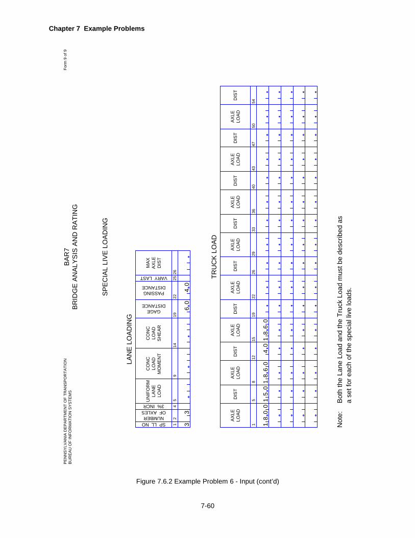
Chapter 7 Example Problems
7-60
Figure 7.6.2 Example Problem 6 - Input (cont’d)
12
SP LL NO
45
914
CO
NC
LOA
DM
OM
EN
T
LAN
E L
OA
DIN
G
UN
IFO
RM
LAN
ELO
AD
2226
19
GAGEDISTANCE
NUMBEROF AXLES3% INCR
CO
NC
LOA
DS
HE
AR
PASSINGDISTANCE
25
VARY LAST
MA
XA
XLE
DIS
T
1
TRU
CK
LO
AD
8
AX
LELO
AD
5DIS
TA
XLE
LOA
D
12
DIS
TA
XLE
LOA
D
15
DIS
TA
XLE
LOA
D
19
DIS
TA
XLE
LOA
D
22
DIS
TA
XLE
LOA
D
40
DIS
TA
XLE
LOA
D
47
DIS
TA
XLE
LOA
D
54
DIS
T
SP
EC
IAL
LIV
E L
OA
DIN
G
Not
e:
Bot
h th
e La
ne L
oad
and
the
Truc
k Lo
ad m
ust b
e de
scrib
ed a
sa
set f
or e
ach
of th
e sp
ecia
l liv
e lo
ads.
2629
3336
4350
BA
R7
BR
IDG
E A
NA
LYS
IS A
ND
RA
TIN
GP
EN
NS
YLV
AN
IA D
EP
AR
TME
NT
OF
TRA
NS
PO
RTA
TIO
NB
UR
EA
U O
F IN
FOR
MA
TIO
N S
YS
TEM
SFo
rm 9
of 9
33
06
04
00
80
15
86
01
10
40
86
1
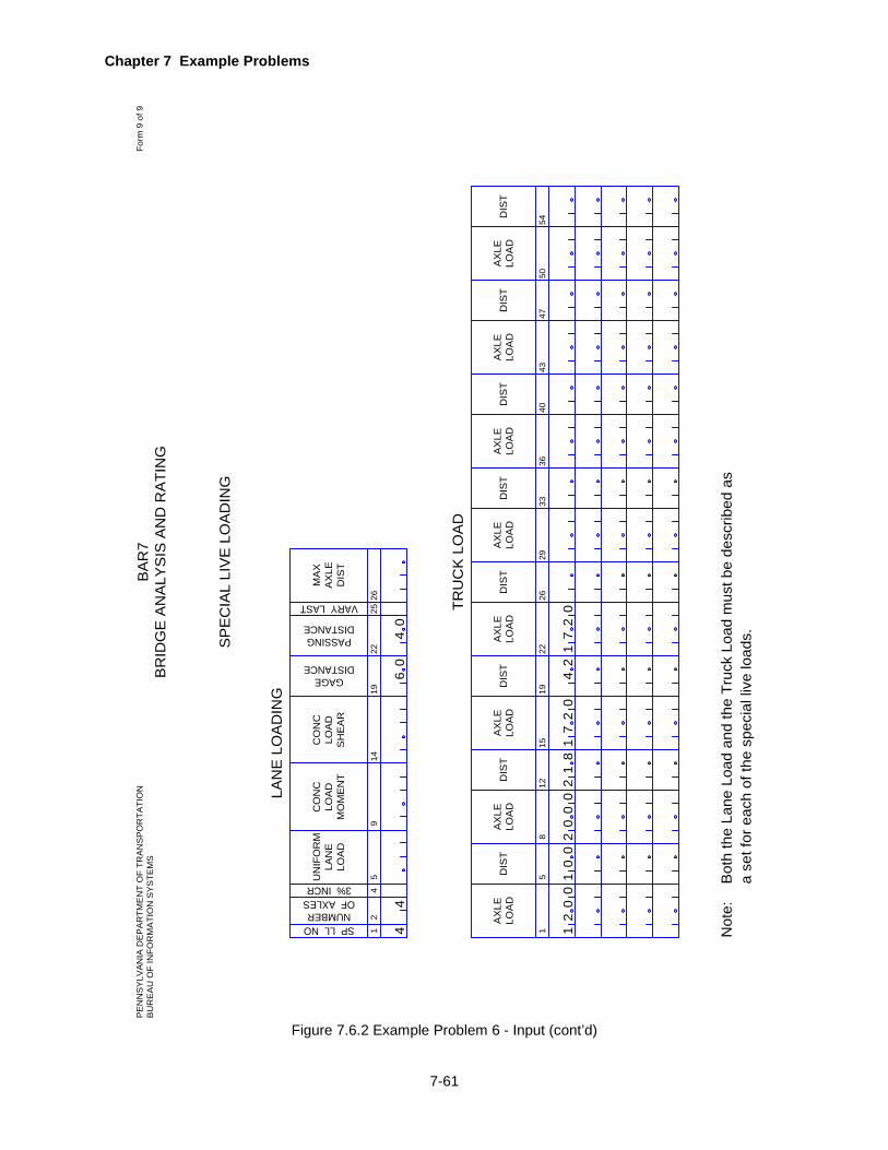
Chapter 7 Example Problems
7-61
Figure 7.6.2 Example Problem 6 - Input (cont’d)
12
SP LL NO
45
914
CO
NC
LOA
DM
OM
EN
T
LAN
E L
OA
DIN
G
UN
IFO
RM
LAN
ELO
AD
2226
19
GAGEDISTANCE
NUMBEROF AXLES3% INCR
CO
NC
LOA
DS
HE
AR
PASSINGDISTANCE
25
VARY LAST
MA
XA
XLE
DIS
T
1
TRU
CK
LO
AD
8
AX
LELO
AD
5DIS
TA
XLE
LOA
D
12
DIS
TA
XLE
LOA
D
15
DIS
TA
XLE
LOA
D
19
DIS
TA
XLE
LOA
D
22
DIS
TA
XLE
LOA
D
40
DIS
TA
XLE
LOA
D
47
DIS
TA
XLE
LOA
D
54
DIS
T
SP
EC
IAL
LIV
E L
OA
DIN
G
Not
e:
Bot
h th
e La
ne L
oad
and
the
Truc
k Lo
ad m
ust b
e de
scrib
ed a
sa
set f
or e
ach
of th
e sp
ecia
l liv
e lo
ads.
2629
3336
4350
BA
R7
BR
IDG
E A
NA
LYS
IS A
ND
RA
TIN
GP
EN
NS
YLV
AN
IA D
EP
AR
TME
NT
OF
TRA
NS
PO
RTA
TIO
NB
UR
EA
U O
F IN
FOR
MA
TIO
N S
YS
TEM
SFo
rm 9
of 9
44
06
04
07
21
42
07
21
00
20
10
00
02
81
21

Chapter 7 Example Problems
7-62
EXAMPLE PROBLEM 7
7.7.1 Problem Description
This is an example of how to analyze and rating a pony truss bridge for the following:
1. Gusset plate analysis. 2. Olny truss stability check at floorbeam location 2. 3. Live load = K. 4. Load factor method rating for members with or without eccentricity.
7.7.2 Input
The bridge data file is created in the following input lines. Please note that these may or may not
fake numbers which may or may not reflect the actual information in the plan.
1. Project Identification
• Bridge Type is “TFS”
• The SLC LEVEL is left blank since the Safe Load Capacity Ratings are not desired.
• "D" is entered for LANES indicating that the ratings are desired based on one lane loaded
as described later.
• The bridge is to be analyzed for the HS20, ML80, TK527, PA58, and AASHTO Type 3
loadings, and therefore a "K" is coded for LIVE LOAD.
• OUTPUT option equal to 0 is used so that all computed values will be printed.
• Impact factor will be calculated by the program as per AASHTO Specifications. This is the
default when this item is left blank.
• The GAGE DISTANCE of 6 feet as specified in the AASHTO Manual is the default when
left blank.
• The PASSING DISTANCE of 4 feet as specified in the AASHTO Manual is the default when
left blank. This is to give a 2-foot distance from curb to outside wheel for the single lane
and 4-foot distance between the outside wheels of two side-by-side trucks.
• PONY TRUSS = Y
2. Bridge Cross Section and Loading
• DECK WIDTH is 34 feet.
• OVERHANG is left blank because the continuity of the floorbeam is not to be considered.
• CENTERLINE OF TRUSS TO CURB distance and ROADWAY WIDTH is 2.5 feet
• ROADWAY WIDTH is 31.08 feet.
• DISTRIBUTION FACTORS for SHEAR is 0.808, DISTRIBUTION FACTORS for MOMENT
is 0.470, and DISTRIBUTION FACTORS for DEFLECTion is 0.286.
• SLAB THICKness is 8 feet.

Chapter 7 Example Problems
7-63
• DL1 is left blank since the dead loads acting on a truss are entered separately under
TRUSS DEAD LOADS.
• DL2 is 0.410 kips/ft.
• F'C and N are left blank because there is no composite action in the superstructure.
• Since the truss is symmetric about the joint at the center of the span, "Y" is entered for
SYMMETRY.
• The live load is to be applied at the lower joints, so "L" is entered for L.
• The total NO. OF PANELS is 7.
• Truss members have riveted end connections, so "R" is entered for END COND.
• "S" is entered for CORS because the Secant Formula is to be used in determining the
allowable compression in a truss member with end eccentricity.
• For the analysis of this truss, the hinged support (HINGE) is at joint L 0.
• The effect of temperature change is not to be considered for deflection computations, so
TEMP CHANGE is left blank.
• END BRG is “L” because the bearing at the abutment is located at the lower joint.
• STRINGER DL1 is 0.110 kips/ft and FLOORBEAM DL1 is 0.016 kips/ft
• GUSSET ANALYSIS is “Y” is entered for gusset plate analysis and rating.
3. Span Lengths
• This is a simple span truss with a span length of 112 feet, measured center-to-center of
bearing.
• “S” is entered for CONT.
4. Traffic Lanes
5. Stringer Span Lengths
• Since this is a truss type bridge and stringers are to be analyzed as simple spans over
floorbeams, CONT. is equal to "S". Due to symmetry, only the first four STRINGER SPAN
LENGTHS need to be entered for the program to rate all floorbeams.
6. Stringer Locations
• Distances of all 7 stringers from the centerline of the left truss are entered.
7. Truss Geometry
8. Truss Dead load
9. Truss Member Properties
• All truss member properties left to the point of symmetry were computed and entered with
the following recommended order which is the same as that of output:
Top chords: U01U02, U02U03, and U03U04
Bottom chords: L00L01, L01L02, L02L03, and L03L04
Diagonal chords: L00U01, L02U01, L03U02, L03U04, and L04U03
Vertical chords: L01U01, L02U02, L03U03, and L04U04

Chapter 7 Example Problems
7-64
• The yield stress of all truss members was determined to be 30 ksi and the ultimate stress
of all truss members was determined to be 60 ksi.
• For pony truss stability check at floorbeam location 2, the Iy = 425 in^4 of the vertical
member, L01U01, must be entered.
• For member L00U01, the eccentricity = 1, flange width = 21, and c = 5.7 were entered to
trigger the computation of allowable tensile/compressive stress (using working stress
method) and axial tension/compression capacity (using load factor method) due to
eccentricity.
10. Additional Truss Member Properties for Load Factor Method
• These additional truss member properties are required for load factor rating and pony truss
stability analysis. These member properties shall be computed carefully per the AASHTO
Guide Spec for Strength Design of Truss Bridges.
• All truss member properties left to the point of symmetry were computed and entered with
the following recommended order which is the same as that of output:
Top chords: U01U02, U02U03, and U03U04
Bottom chords: L00L01, L01L02, L02L03, and L03L04
Diagonal chords: L00U01, L02U01, L03U02, L03U04, and L04U03
Vertical chords: L01U01, L02U02, L03U03, and L04U04
11. Steel Beam Properties
• For pony truss stability check at floorbeam location 2, the steel member properties of
floorbeam, F2, must be entered.
12. Gusset Plate properties
• All gusset plate properties left to the point of symmetry were entered with the following
recommended order which is the same as that of output:
Upper joints: U01, U02, U03, and U04
Lower joints: L01, L02, L03, and L04
13. Gusset Plate Member Properties
• All gusset plate member properties left to the point of symmetry were entered with the
following recommended order which is the same as that of output:
Upper joints: U01, U02, U03, and U04
Lower joints: L01, L02, L03, and L04
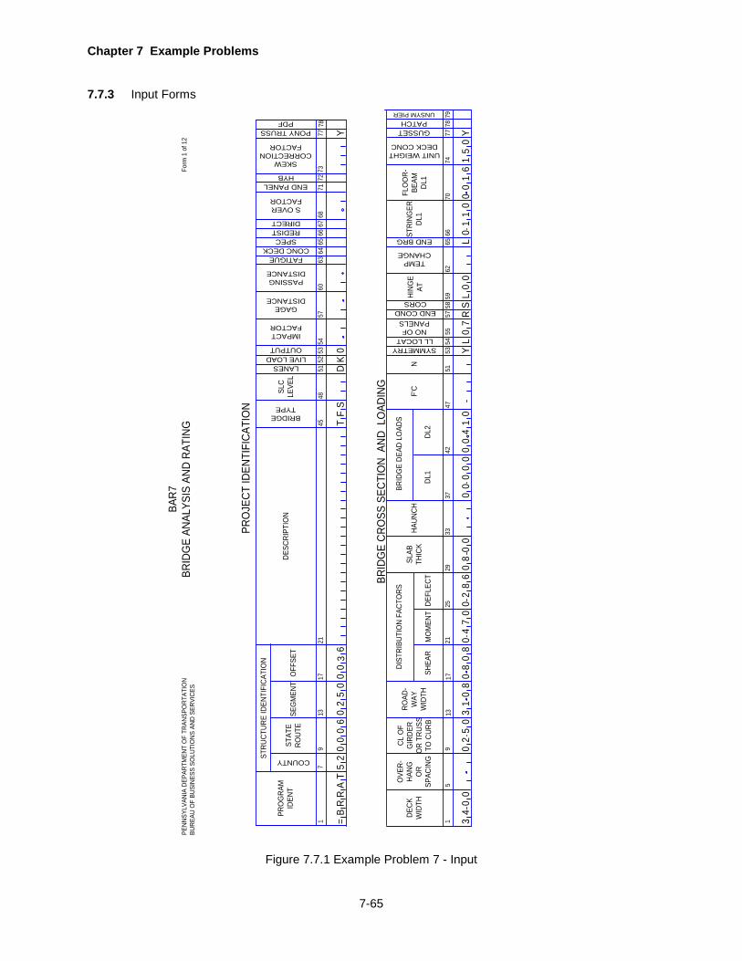
Chapter 7 Example Problems
7-65
7.7.3 Input Forms
COUNTY
17
PRO
GRA
MID
ENT
STRU
CTUR
E ID
ENTI
FICA
TIO
N
STAT
ERO
UTE
DESC
RIPT
ION
4548
5154
5760
67
BRIDGETYPE
913
1721
SEG
MEN
TO
FFSE
T
IMPACTFACTOR
GAGEDISTANCE
PASSINGDISTANCE
63
PRO
JECT
IDEN
TIFI
CATI
ON
15
DECK
WID
TH
DIST
RIBU
TIO
N FA
CTO
RS
MO
MEN
T
4751
5362
709
1317
21
DEFL
ECT
66
BRID
GE
CRO
SS S
ECTI
ON
AND
LO
ADIN
G
SHEA
R
2529
3342
DL1
F'CSL
CLE
VEL
5253
LANESLIVE LOADOUTPUT
FATIGUE 6465
66
CONC DECKSPEC
REDISTDIRECT 68
S OVERFACTOR
OVE
R-HA
NG OR
SPAC
ING
CL O
FG
IRDE
RO
R TR
USS
TO C
URB
ROAD
-W
AYW
IDTH
SLAB
THIC
KHA
UNCH
37
DL2
BRID
GE
DEAD
LO
ADS
N
SYMMETRYLL LOCAT
NO OFPANELS
END COND
5455
5758
59CORSHING
EAT
TEMPCHANGE
65
STRI
NGER
DL1
SKEW CORRECTION
FACTOR
END BRG
=B
RR
AT
PENN
SYLV
ANIA
DEP
ARTM
ENT
OF
TRAN
SPO
RTAT
ION
BURE
AU O
F BU
SINE
SS S
OLU
TIO
NS A
ND S
ERVI
CES
Form
1 o
f 12
BAR7
BRID
GE
ANAL
YSIS
AND
RAT
ING
71
END PANEL 72
HYB
FLO
OR-
BEAM
DL1
73
PONY TRUSS
77
UNIT WEIGHT DECK CONC
7477
GUSSET 78
PATCH 79
UNSYM PIER
52
00
06
02
50
00
36
TF
SD
K0
Y Y0
51
L0
01
60
11
00
0L
00
43
10
52
30
08
00
00
88
68
24
07
08
00
00
00
00
04
1Y
L0
SR
70
78
Figure 7.7.1 Example Problem 7 - Input
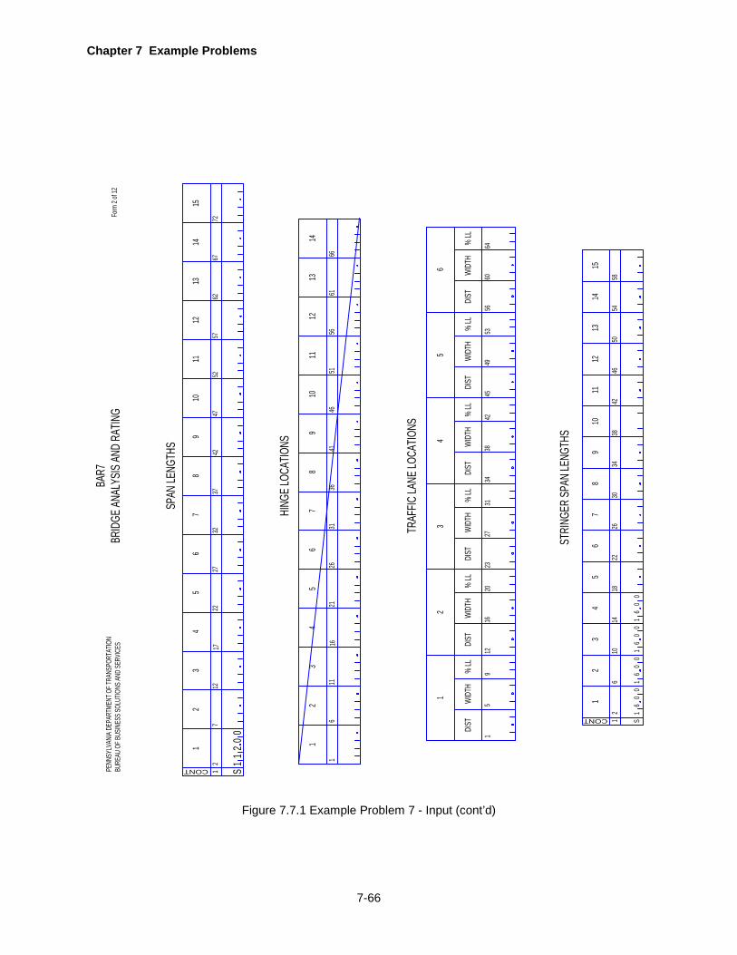
Chapter 7 Example Problems
7-66
Form
2 of
12
12
19
CONT
712
1722
3
SPAN
LENG
THS
24
2732
3742
67
85
4752
5762
6772
1011
1213
1415
HING
E LOC
ATIO
NS
19
TRAF
FIC LA
NE LO
CATIO
NS
5
1
DIST
WIDT
H%
LL
1220
16
2
DIST
WIDT
H%
LL
2331
27
3
DIST
WIDT
H%
LL
3442
38
4
DIST
WIDT
H%
LL
4553
49
5
DIST
WIDT
H%
LL
5664
60
6
DIST
WIDT
H%
LL
STRI
NGER
SPAN
LENG
THS
BAR7
BRID
GE AN
ALYS
IS AN
D RA
TING
PENN
SYLV
ANIA
DEPA
RTME
NT O
F TRA
NSPO
RTAT
ION
BURE
AU O
F BUS
INES
S SOL
UTIO
NS AN
D SE
RVIC
ES
1
19
611
1621
32
4
2631
3641
67
85
4651
5661
66
1011
1213
14
S2
00
11
12
111
CONT
610
1418
32
4
2630
3442
65
4650
5458
1213
14
22
78
9
38
1015
1S
06
00
61
00
06
10
06
1
Figure 7.7.1 Example Problem 7 - Input (cont’d)
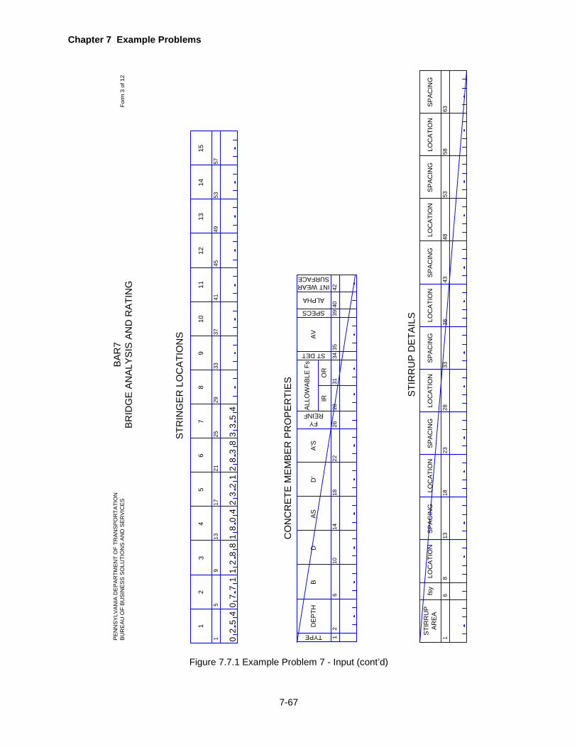
Chapter 7 Example Problems
7-67
12D
EP
TH
TYPE
610
1418
D
CO
NC
RE
TE M
EM
BE
R P
RO
PE
RTI
ES
BA
S
2628
3440
A'S
D'
STI
RR
UP
DE
TAIL
S
22
FYREINFA
LLO
WA
BLE
Fs
AV
31
IRO
R
ST DET 3539
SPECS
ALPHA
42
INT WEARSURFACE
BA
R7
BR
IDG
E A
NA
LYS
IS A
ND
RA
TIN
GP
EN
NS
YLV
AN
IA D
EP
AR
TME
NT
OF
TRA
NS
PO
RTA
TIO
NB
UR
EA
U O
F B
US
INE
SS
SO
LUTI
ON
S A
ND
SE
RV
ICE
SFo
rm 3
of 1
2
STR
ING
ER
LO
CA
TIO
NS
1
STI
RR
UP
AR
EA
68
13
LOC
ATI
ON
fsy
SP
AC
ING
1823
LOC
ATI
ON
SP
AC
ING
2833
LOC
ATI
ON
SP
AC
ING
3843
LOC
ATI
ON
SP
AC
ING
4853
LOC
ATI
ON
SP
AC
ING
5863
LOC
ATI
ON
SP
AC
ING
1
111
59
1317
32
4
2129
3741
78
96
4549
5357
1213
1415
5
2533
10
52
00
71
74
12
81
80
48
35
42
83
38
23
21
Figure 7.7.1 Example Problem 7 - Input (cont’d)
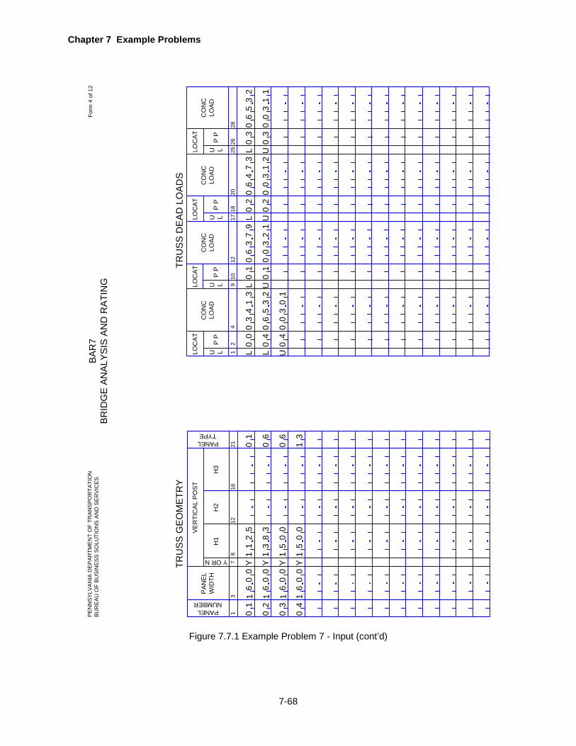
Chapter 7 Example Problems
7-68
TRU
SS
GE
OM
ETR
YTR
US
S D
EA
D L
OA
DS
BA
R7
BR
IDG
E A
NA
LYS
IS A
ND
RA
TIN
GFo
rm 4
of 1
2P
EN
NS
YLV
AN
IA D
EP
AR
TME
NT
OF
TRA
NS
PO
RTA
TIO
NB
UR
EA
U O
F B
US
INE
SS
SO
LUTI
ON
S A
ND
SE
RV
ICE
S
12P
P
4
U LLOC
AT
CO
NC
LOA
D
910P
P
12
U LLOC
AT
CO
NC
LOA
D
1718P
P
20
U LLOC
AT
CO
NC
LOA
D
2526P
P
28
U LLOC
AT
CO
NC
LOA
D
40L
0L U
L00
0
03
20
31
4 30
0
35
6
14
1
U0
0
6
00
1
0
2
3
1
79
46
02
L0
3
3
02
U
73
L U2
0
0
13
0
35
60
2
00
13
03
1
13
PA
NE
L W
IDTH
PANELNUMBER
712
16
Y OR N
H3
218
H1
H2
VE
RTI
CA
L P
OS
T
PANELTYPE
11
0
2
0
300
06
0
16
411
0
0 00
00
66
Y1
21
5
1
YYY3
83
11
0
0
5
0
05
0
1 66
10
3
0
Figure 7.7.1 Example Problem 7 - Input (cont’d)
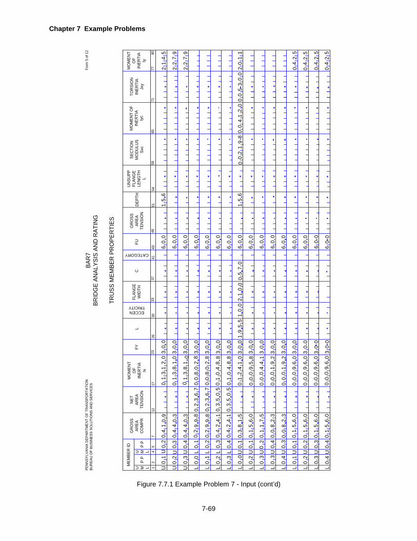
Chapter 7 Example Problems
7-69
BAR
7BR
IDG
E AN
ALYS
IS A
ND
RAT
ING
PEN
NSY
LVAN
IA D
EPAR
TMEN
T O
F TR
ANSP
OR
TATI
ON
BUR
EAU
OF
BUSI
NES
S SO
LUTI
ON
S AN
D S
ERVI
CES
Form
5 o
f 12
TRU
SS M
EMBE
R P
RO
PER
TIES
12P
P
4
U M LMEM
BER
ID
712
GR
OSS
AREA
CO
MPR
1723
MO
MEN
TO
FIN
ERTI
AIx
26
L
30
FY
ECCENTRICITY
5
U M LP
P
NET
AREA
TEN
SIO
N
FLAN
GE
WID
THC
CATEGORY
GR
OSS
AREA
TEN
SIO
NFU
3337
4143
46
SEC
TIO
N
MO
DU
LUS
Sxc
MO
MEN
T O
F IN
ERTI
AIy
c
TOR
SIO
NIN
ERTI
AJx
y
5154
65
DEP
TH
71
UN
SUPP
FLAN
GE
LEN
GTH
L
59
MO
MEN
TO
FIN
ERTI
AIy
8077
U U U L L L L
01
60
0 00
6
00
6
00
6
00
6
00
6
00
6
00
6
00
6
00
6
00
6
00
6
00
3
00
6
00
6
00
6
00
6
00
3
00
3
00
3
00
3
00
3
00
3
00
3
00
3
00
3
00
3
00
3
00
3
00
3
00
3
00
3
31
0
31
00
18
02
1
LLLL
0 0 0 0 0 0 0 0 0
2 32
U U U L L L L
0 0 0 0 0 0 04321432
3 0 1
31
18
0 8
0 00
80
2
80
08
02
80
10
48
80
10
48
L L L LL
U U U U U U U U U
04
10
9
04
40
3
04
40
3
02
99
8
02
99
8
04
24
1
04
24
1
76
32
0
76
32
0
50
53
0
50
53
0
0 2 3 3 4 1 2 3 4000000
10 0 0 0 0 0 0 0 0
1 2 4 3 1 2 3 4
00
82
3
01
56
0
01
56
0
01
56
0
01
56
0
00
01
92
00
09
60
00
09
60
00
09
60
00
09
60
04
25
04
25
04
25
04
25
21
45
22
79
22
79
15
6
15
60
02
19
80
21
40
05
00
30
02
01
10
38
15
01
56
0
01
17
5
00
82
3
01
24
10
00
09
58
00
04
41
00
01
92
19
55
10
02
10
00
57
0
Figure 7.7.1 Example Problem 7 - Input (cont’d)

Chapter 7 Example Problems
7-70
BAR7
BRID
GE
ANAL
YSIS
AND
RAT
ING
Form
6 o
f 12
ADDI
TIO
NAL
TRUS
S M
EMBE
R PR
OPE
RTIE
S FO
R LO
AD F
ACTO
R M
ETHO
D
PENN
SYLV
ANIA
DEP
ARTM
ENT
OF
TRAN
SPO
RTAT
ION
BURE
AU O
F BU
SINE
SS S
OLU
TIO
NS A
ND S
ERVI
CES
LU
40
04
45P
P
7
U M LMEM
BER
ID
1016
SECT
ION
MO
DULU
S G
ROSS
TENS
ION
2228
MU
8
U M LP
P
SECT
ION
MO
DULU
SNE
TTE
NSIO
N
3538
4142
EQUI
M
OM
FA
C
PLAS
SH
APE
FAC
S H A P E
SECT
ION
MO
DULU
S G
ROSS
COM
PR
ATM
CA
RD
1
T
BOX
AREA
BOX
S/T
Iy2
5258
47
MEM
HEIG
HT
AM
AM
T
AM
T
AM
T
AM
T
AM
T
AM
T
AM
T
AM
T
AM
T
AM
T
AM
T
AM
T
AM
T
AM
T
U U U L L L L
01
LLLL
0 0 0 0 0 0 0 0 0
2 32
U U U L L L L
0 0 0 0 0 0 04321432
3 0 1
L L LL
U U U U U U U U
0 2 3 3 4 1 2 300000
10 0 0 0 0 0 0 0
1 2 4 3 1 2 3
AM
T
00
10
96
69
01
00
69
01
00
00
11
70
07
11
00
00
11
70
07
11
00
00
10
76
67
01
00
00
10
76
67
01
00
00
14
04
40
41
00
00
14
04
40
41
00
00
10
23
32
01
00
00
07
06
60
70
00
00
05
15
51
50
00
00
13
56
65
31
00
00
03
56
65
30
00
00
07
06
60
70
00
00
07
06
60
70
00
00
07
06
60
70
00
00
07
06
60
70
00
07
11
00
07
11
00
67
01
00
67
01
00
40
41
00
40
41
00
32
01
00
60
70
00
51
50
00
65
31
00
65
30
00
60
70
00
60
70
00
60
70
00
60
70
00
31
27
08
5
12
80
85
12
80
85
12
70
85
12
70
85
13
30
85
3 3
13
30
85
12
50
85
11
00
85
11
00
85
11
00
85
11
00
85
11
00
85
11
00
85
11
00
85
11
00
85
3 33
66
51
01
42
10
30
53
20
0
Figure 7.7.1 Example Problem 7 - Input (cont’d)

Chapter 7 Example Problems
7-71
12
STEE
L M
EMBE
R P
RO
PER
TIES
38
WF
BEA
MM
OF
IO
R A
NG
LEVE
RT
LEG
1621
WF
BEA
MAR
EAO
R A
NG
LEH
OR
Z L
EG
26
FLAN
GE
WID
TH
31
FLAN
GE
OR
ANG
LETH
ICK
VARIES
RAN
GE
WF
BEA
MO
R W
EBPL
ATE
DEP
TH
WEB
THIC
KTH
ICK
WID
TH
G F OR SSPAN NO
9
SECT TYPE
3237
4246
THIC
KW
IDTH
5155
60
COMPOSITE 6164
6770
75
TOP
PLA
TEBO
TTO
M P
LATE
FYFY TO
PFY BO
TC
GTO
PC
GBO
T
HYB
RID
UN
SYM
MET
RIC
AL
BAR
7BR
IDG
E AN
ALYS
IS A
ND
RAT
ING
PEN
NSY
LVAN
IA D
EPAR
TMEN
T O
F TR
ANSP
OR
TATI
ON
BUR
EAU
OF
BUSI
NES
S SO
LUTI
ON
S AN
D S
ERVI
CES
Form
7 o
f 12
F2
01
80
01
10
37
90
05
80
72
00
00
33
00
57
51
00
51
18
1W
N3
00
N3
00
S0
00
00
00
76
86
00
13
03
20
00
08
10
00
57
00
05
50
82
W
Figure 7.7.1 Example Problem 7 - Input (cont’d)
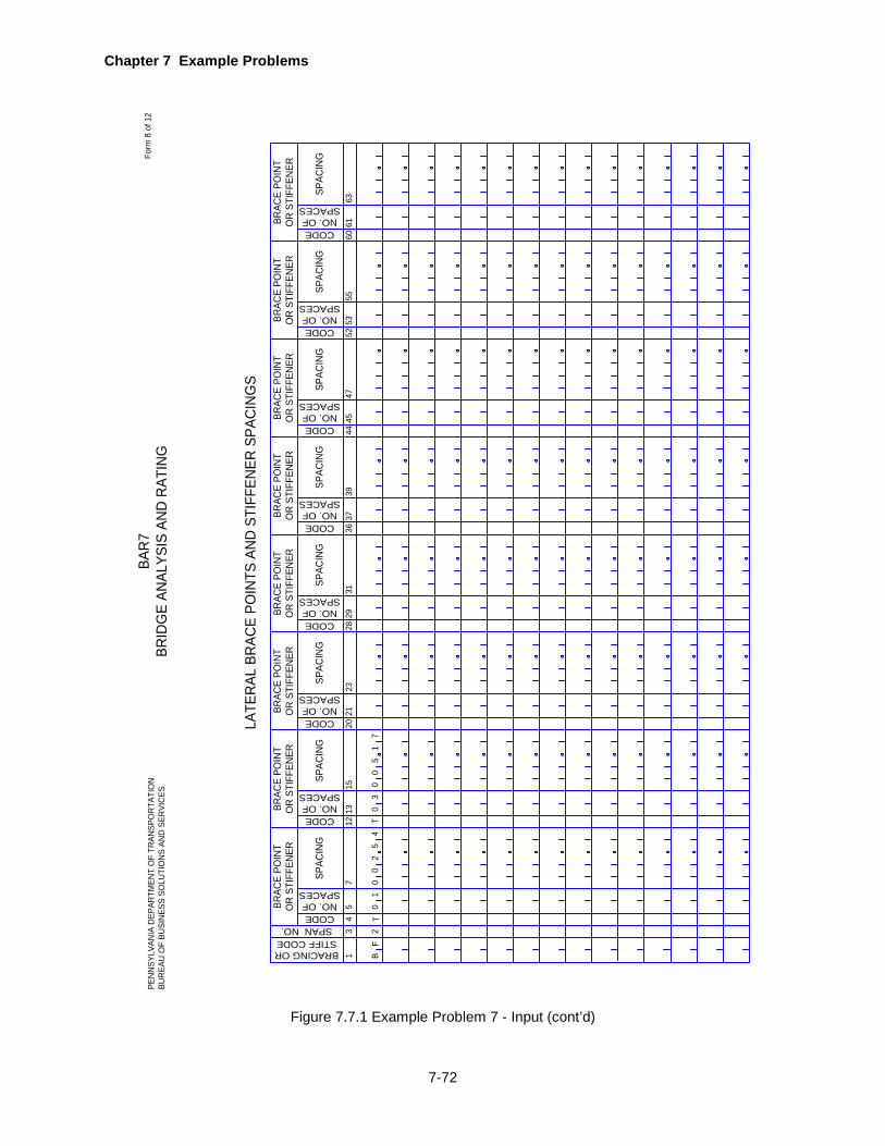
Chapter 7 Example Problems
7-72
LATE
RAL
BR
ACE
POIN
TS A
ND
STI
FFEN
ER S
PAC
ING
S
BAR
7BR
IDG
E AN
ALYS
IS A
ND
RAT
ING
Form
8 o
f 12
PEN
NSY
LVAN
IA D
EPAR
TMEN
T O
F TR
ANSP
OR
TATI
ON
BUR
EAU
OF
BUSI
NES
S SO
LUTI
ON
S AN
D S
ERVI
CES
13
4
BRAC
E PO
INT
OR
STI
FFEN
ER
75
CODE
SPAC
ING
BRACING ORSTIFF CODESPAN NO.
1215
13CODE
2023
21CODE
2831
29CODENO. OF
SPACES
3639
37CODE
4447
45CODE
5255
53CODE
6063
61CODE
SPAC
ING
SPAC
ING
SPAC
ING
SPAC
ING
SPAC
ING
SPAC
ING
SPAC
ING
BRAC
E PO
INT
OR
STI
FFEN
ERBR
ACE
POIN
TO
R S
TIFF
ENER
BRAC
E PO
INT
OR
STI
FFEN
ERBR
ACE
POIN
TO
R S
TIFF
ENER
BRAC
E PO
INT
OR
STI
FFEN
ERBR
ACE
POIN
TO
R S
TIFF
ENER
BRAC
E PO
INT
OR
STI
FFEN
ER
NO. OFSPACES
NO. OFSPACES
NO. OFSPACES
NO. OFSPACES
NO. OFSPACES
NO. OFSPACES
NO. OFSPACES
BF
2T
01
00
25
4T
03
00
51
7
Figure 7.7.1 Example Problem 7 - Input (cont’d)

Chapter 7 Example Problems
7-73
LOC1
14
GU
S C
ARD
YIEL
D
STR
ESS
Fy
4349
615
1115
19
TEN
SILE
ST
RES
SFu
THIC
K
MAX
U
NSU
PPO
RTE
D
EDG
EB
SHEA
R
CAP
ACIT
YO
FFA
STEN
ER
GU
SSET
PLA
TE P
RO
PER
TIES
5566FA
STEN
ERD
IAM
ETER
GU
S
Form
11
of 1
2BA
R7
BRID
GE
ANAL
YSIS
AN
D R
ATIN
G
LOC2
7
LEN
GTH
Ha
LEN
GTH
Hb
LEN
GTH
Hc
ECC
ENTR
ICIT
YEa
ECC
ENTR
ICIT
YEb
ECC
ENTR
ICIT
YEc
2531
3769
PEN
NSY
LVAN
IA D
EPAR
TMEN
T O
F TR
ANSP
OR
TATI
ON
BUR
EAU
OF
BUSI
NES
S SO
LUTI
ON
S AN
D S
ERVI
CES
SU
GS
UG
SU
GS
UG
SU
GS
UG
SU
GS
UG
U0
10
30
00
43
70
75
00
00
35
50
00
87
50
25
00
00
55
20
00
05
00
00
05
00
08
89
00
00
05
30
GU
S
U0
20
30
00
43
70
45
75
00
26
25
00
87
50
25
00
00
59
10
00
05
00
00
05
00
08
79
00
00
55
20
GU
S
U0
30
30
00
43
70
43
00
00
24
00
00
87
50
25
00
00
59
10
00
05
00
00
05
00
05
79
00
00
03
20
GU
S
U0
40
30
00
43
70
43
00
00
23
00
00
87
50
25
00
00
59
10
00
05
00
00
05
00
05
79
00
00
04
20
GU
S
L0
00
30
00
50
00
51
50
00
47
87
50
87
50
25
00
00
05
10
52
66
00
00
00
00
00
57
00
57
87
40
GU
S
L0
10
30
00
43
70
16
00
00
31
00
00
87
50
25
00
00
00
00
00
05
00
00
05
00
00
57
00
00
01
30
GU
S
L0
20
30
00
43
70
46
00
00
31
00
00
87
50
25
00
00
05
20
00
05
00
00
05
00
00
57
00
00
01
30
GU
S
L0
30
30
00
43
70
45
00
00
31
00
00
87
50
25
00
00
55
10
00
05
00
00
05
00
00
57
00
00
01
30
GU
S
L0
40
30
00
43
70
45
00
00
31
00
00
87
50
25
00
00
05
10
00
05
00
00
05
00
00
57
00
00
01
30
GU
S
Figure 7.7.1 Example Problem 7 - Input (cont’d)
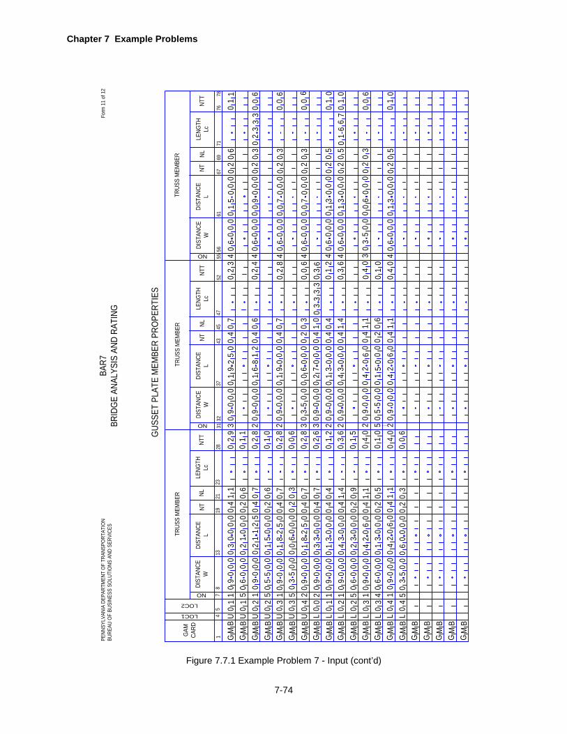
Chapter 7 Example Problems
7-74
1GAM
CA
RD
TRUS
S M
EMBE
R
694
519
21
NT
GUS
SET
PLAT
E M
EMBE
R PR
OPE
RTIE
S
2331
DIST
ANCE
WDI
STAN
CEL
Form
11
of 1
2BA
R7BR
IDG
E AN
ALYS
IS A
ND R
ATIN
G
GM
B
LOC1
LOC2
8
NLLE
NGTH
Lc
NO 713
4345
NT
47
DIST
ANCE
WDI
STAN
CEL
32
NLLE
NGTH
Lc
37
NO
5561
76
NT 67
DIST
ANCE
WDI
STAN
CEL
NL
52
NO
LENG
THLc
TRUS
S M
EMBE
RTR
USS
MEM
BER
G GB B
MM
NTT
2871
NTT
NTT
5678
PENN
SYLV
ANIA
DEP
ARTM
ENT
OF
TRAN
SPO
RTAT
ION
BURE
AU O
F BU
SINE
SS S
OLU
TIO
NS A
ND S
ERVI
CES
U0
11
09
00
01
14
00
00
03
0
GB
MG
BM
GB
MG
BM
GB
MG
BM
GB
MG
BM
GB
MG
BM
GB
MG
BM
GB
MG
BM
GB
MG
BM
GB
M
02
93
09
00
00
19
25
40
07
02
34
06
00
00
15
00
00
26
00
U0
1U
02
U0
2U
03
U0
3U
04
L0
0L
01
L0
2L
02
L0
3L
03
L0
4L
04
5 1 5 1 5 2 2 1 1 5 1 4 1 5
06
00
06
02
00
00
12
00
90
00
70
40
52
11
20
05
50
06
02
00
00
51
00
90
00
70
40
05
28
10
03
50
03
02
00
00
60
00
90
00
70
40
05
28
10
09
00
07
04
00
00
33
00
90
00
40
40
00
03
10
09
00
04
14
00
00
34
00
60
00
90
20
00
03
20
09
00
01
14
00
60
24
00
60
00
50
20
00
03
10
09
00
01
14
00
60
24
00
35
00
30
20
00
00
60
01
10
28
20
90
00
01
68
14
00
62
01
00
28
20
90
00
01
90
04
00
70
00
60
28
30
35
00
00
60
02
00
30
02
63
09
00
00
27
00
40
10
00
12
20
90
00
01
30
04
00
40
03
62
09
00
00
43
00
40
14
00
15
04
02
09
00
00
42
06
40
11
00
10
50
55
00
01
50
02
00
60
04
02
09
00
00
42
06
40
11
00
06
01
1
03
33
30
36
02
44
06
00
00
09
00
00
23
0
02
84
06
00
00
07
00
00
23
0
00
64
06
00
00
07
00
00
23
0
01
24
06
00
00
13
00
00
25
00
36
40
60
00
01
30
00
02
50
04
03
03
50
00
06
00
00
23
0
04
04
06
00
00
13
00
00
25
0
00
00
00
01
01
00
01
6 6 6 0 0 6 0
33
32
0 01
66
7
01
0
Figure 7.7.1 Example Problem 7 - Input (cont’d)

8-1
TECHNICAL QUESTIONS AND REVISION REQUESTS
This chapter contains reply forms to make it easier for users to convey their questions, problems or comments to
the proper unit within the Department. General procedures for using these forms are given. Users should keep the
forms in the manual as master copies which can be reproduced as needed. They are also included as a Word
template on the disk that has been provided for the program.
TECHNICAL QUESTIONS
Technical questions related to the interpretations of the design specifications as implemented in this program, why
certain assumptions are made, applicability and limitations of this program, and other questions not related to the
operation of this program can be directed to the appropriate person in PennDOT using this form or the information
provided on this form. Please review the information provided in this User’s Manual and the references given in
Chapter 1 before submitting this form for processing or calling for assistance. The completed form should be sent
to the Bridge Quality Assurance Division (see form for complete address).
REVISION REQUESTS
This form is to be used to report suspected program malfunctions that may require revisions to the program. It can
also be used to request revisions that may be required due to changes in specifications and for the enhancement
of the program. Unexpected or incorrect output, rejection of input data, endless program cycling, and program
abortion are examples of program malfunctions. Users are requested to review their input data and the program
User’s Manual before submitting this form for processing.
This form may also be used to submit suggestions for improving the User’s Manual for this program. Suggestions
might include typographical error correction, clarification of confusing sections, expansion of certain sections,
changes in format, and the inclusion of additional information, diagrams, or examples.
The completed form should be sent to the Engineering Software Section via mail, fax, or e-mail.

Chapter 8 Technical Questions and Revision Requests
8-2
This page is intentionally left blank.

Chapter 8 Technical Questions and Revision Requests
8-3
BAR7 TECHNICAL QUESTIONS
This form is to be used to ask questions on technical issues related to this engineering program. Questions on the interpretations of the design specifications as implemented in this program, why certain assumptions are made by the program and other questions not related to the operation of this program may be submitted using this form or by calling the telephone number listed in this form. Users are requested to read the User’s Manual, LRFD Specifications and DM-4 before submitting this form or calling to ask questions. CONTACT PERSON:_______________________________________ DATE: ____________________ ORGANIZATION:______________________________________ PHONE:____________________ E-MAIL ADDRESS:______________________________________ FAX: ____________________ PROGRAM VERSION:_________________________ Clearly state your question(s) and attach documentation you feel would be helpful in answering your question(s). If you require more space, use additional 8½ x 11 sheets of plain paper. FORWARD COMPLETED FORM TO: Pennsylvania Department of Transportation
Bridge Design and Technology Division P.O. Box 3560 Harrisburg, PA 17105-3560 PHONE: (717) 787-2881 FAX: (717) 787-2882
FOR DEPARTMENT USE ONLY
RECEIVED BY: ________________ ASSIGNED TO: ___________________ DATE: _____________

Chapter 8 Technical Questions and Revision Requests
8-4
This page is intentionally left blank.

Chapter 8 Technical Questions and Revision Requests
8-5
BAR7 REVISION REQUEST
This form is to be used to report suspected program malfunctions, or to request revisions to the program or its documentation. Users are requested to review their input data and the program User’s Manual before submitting this form. CONTACT PERSON:_______________________________________ DATE: ____________________ ORGANIZATION:_______________________________________ PHONE: ___________________ E-MAIL ADDRESS:_______________________________________ FAX: ____________________ PROGRAM VERSION: _______________ Define your problem and attach samples and/or documentation you feel would be helpful in correcting the problem. If the input data is more than 4 or 5 lines, Licensees should provide the input data file on a diskette. If you require more space, use additional 8½ x 11 sheets of plain paper. FORWARD COMPLETED FORM TO: Pennsylvania Office of Administration
Bureau of Business Solutions and Services, Highway/Engineering Apps Division Engineering Software Section P. O. Box 8213 Harrisburg, PA 17105-8213 PHONE: (717) 783-8822 FAX: (717) 705-5529 E-MAIL: [email protected]
FOR DEPARTMENT USE ONLY RECEIVED BY: ________________ ASSIGNED TO: ___________________ DATE: _____________

Chapter 8 Technical Questions and Revision Requests
8-6
This page is intentionally left blank.


