
Installation description EB06
Design and function
TDI 225-6TDI 265-6
Boa
t eng
ines
from
VO
LKSW
AG
EN M
arin
e

Foreword
This installation manual includes the design and functioning of new developments!The contents will not be updated.
Please see the relevant KD literature for the latest testing, adjustment
and repair instructions!
This installation description explains the procedure for installing all 6 cylinder VOLKSWAGEN Marine boat engines.
General
• Products, that are lot listed in this installation description but which are nevertheless required, should only be sourced from specialist suppliers.
• The professional installation of this engine and its component parts is very important to make sure all components function correctly together in a fault-free manner. Therefore all work must be carried out with the utmost care.
ImportantNote
NEW
EB6-0009

3Superior Technology
Foreword . . . . . . . . . . . . . . . . . . . . . . . . . . . . . . . . . . . . .2
Installation instructions . . . . . . . . . . . . . . . . . . . . . . . . . .4
Exhaust system . . . . . . . . . . . . . . . . . . . . . . . . . . . . . . . .6
Unit mounting / engine mounting . . . . . . . . . . . . . . . . .8
Electrical system . . . . . . . . . . . . . . . . . . . . . . . . . . . . . . 10
Connections to the engine . . . . . . . . . . . . . . . . . . . . . . . . . . . . . . . . . 10
Instrumentation . . . . . . . . . . . . . . . . . . . . . . . . . . . . . . . . . . . . . . . . . . . 13
Overview of instrumentation installation . . . . . . . . . . . . . . . . . . . . . 15
Overview of standard instrumentation installation (optional) . . . 18
Engine installation dimensions . . . . . . . . . . . . . . . . . .22
Engine with Z-drive installation dimensions. . . . . . . .23
Engine with reverse gear unit installation dimensions . . . . . . . . . . . . . . . . . . . . . . . . . . . . . . . . . . .25
Cooling system . . . . . . . . . . . . . . . . . . . . . . . . . . . . . . .27
Engine cooling circuit . . . . . . . . . . . . . . . . . . . . . . . . . . . . . . . . . . . . . . 27
Sea water / fresh water circuit . . . . . . . . . . . . . . . . . . . . . . . . . . . . . . 27
Fuel system . . . . . . . . . . . . . . . . . . . . . . . . . . . . . . . . . . 31
Functional description of the fuel system . . . . . . . . . . . . . . . . . . . . . 31
Engine compartment ventilation . . . . . . . . . . . . . . . . 34
Engine components list . . . . . . . . . . . . . . . . . . . . . . . . .35
Technical Data . . . . . . . . . . . . . . . . . . . . . . . . . . . . . . . 38
Installation dimensions for customizedinstrumentation . . . . . . . . . . . . . . . . . . . . . . . . . . . . . . 40
Installation templatefor standard instrumentation . . . . . . . . . . . . . . . . . . . . 41
Contents

4Superior Technology
• To lift the VOLKSWAGEN Marine boat engine out of its transport container, the three suspension chains or belts must be inserted in the suspension eyes provided (see figure). An engine hoist and suitable suspension device should be used.
• When installing or removing the VOLKSWAGEN Marine boat engine, the suspension eyes provided on the engine (see figure) are to be used.
Note:
When removing the VOLKSWAGEN Marine boat engine from the transport container, make sure that the positioning device for the design cover (see -arrow-) is not damaged by the suspension chains or belts thus creating a risk of breakage. Properly attach the suspension chains or belts to the engine in order to avoid the risk of damage.
• Choose the engine installation location and compartment so that engine maintenance work may be easily carried out.
• Make sure that when installing or removing the engine, there is sufficient free space.
Installation instructions
Qualified specialists of the VOLKS-WAGEN Marine team are at your disposal if you have specific questions or require technical information relating to the installation of the VOLKSWAGEN Marine boat engine.
EB6-0002
Adjustment of the throttle bowden cable on the sender for throttle lever position
Adjust the throttle bowden cable so that there is a difference of 65 mm between idling and full throttle positions (see figure).
Note
To achieve full engine output, the setting of the throttle lever position sender must be strictly observed. After the engine has been started, the value of of the throttle lever position (pedal position sender) can be indicated from 1 - 101% by means of the multifunction display enabling you to control engine performance. Instructions on the operation of the multifunction display are provided in the "Additional operating manual of the multifunction display". EB5-0097
5Superior Technology
Retrofitting of a reverse gear unit to the Volkswagen Marine boat engine
• When retrofitting a reverse gear unit, various details must be observed and components exchanged. Please contact your VOLKSWAGEN Marine dealer for advice.
• For connection of a gearbox neutral position switch (engine with reverse gear unit) see page 12.
Operating an engine with a reverse gear unit
• Observe the instructions in your instruction manual!
Propeller model drive
• When selecting a propeller, ensure that the engine can attain the nominal rotation speed in all operating modes.
Operation with battery isolating diodes
• Operation with battery isolating diodes is not permitted.
• Always use a battery isolation relay. If in doubt, please contact your nearest VOLKSWAGEN Marine dealer.
Connection of a hot water boiler
• If you wish to install a hot water boiler, please contact your nearest VOLKSWAGEN Marine dealer.
If you do not observe the installation guidelines, your VOLKSWAGEN Marine boat engine may be damaged.

6Superior Technology
15 c
m
5 cm
10
11
654321 87
9
Exhaust system
Introduction
VOLKSWAGEN Marine boat engines are operated using wet exhaust systems.
After the exhaust gas collector or turbocharger, the exhaust flow is diverted by the exhaust pipe connection. See water / freshwater is sprayed into the exhaust gas within this exhaust pipe connection.
Note
The water collector (item 5. in the figure) should be dimensioned so that it can accept the total amount of seawater / freshwater that can flow back.
The seawater / freshwater mixes with the exhaust gases, cooling them considerably so that in the remainder of the exhaust system, connection hoses made from rubber and PVC parts, capable of withstanding temperatures up to at least 200 °C, can be used.
Overview of the exhaust system installation
Legend
1. Seawater / freshwater filter2. Engine3. Ventilation unit (fit at least 15 cm above
the water line)4. Exhaust pipe5. Water collector6. Silencer
7. Water line8. Swan-neck throat (the lower edge of the
exhaust gas pipe at the transom outlet must be at least 5 cm above the water line)
9. Transom outlet10. Intake cap11. Sea water / fresh water valve
EB6-0022

7Superior Technology
Note
• The complete exhaust system should be installed with as few pipe bends as possible.
• A minimum pipe cross section* of 100 mm must be maintained.
• Hose connectionsshould always be secured with double hose clips.
• Hose connections and rubber sleeves must be temperature-resistant.
The exhaust system should not be made too long, to ensure that the correct maximum value for the exhaust gas counter pressure is not exceeded.
• TDI 225-6 at 165 kW = max. 350 mbar
• TDI 265-6 at 195 kW = max. 350 mbar
This value should not be exceeded.
EB5-0005
EB6-0001
Legend
1. Screw plug for seawater / fresh water extraction and connection of the temperature sensor (optional)
2. Screw plug for exhaust gas extraction3. Exhaust gas outlet
1 2
3

8Superior Technology
Instructions for installation of the unit mounting
• Do not tension the unit mounting when fitting it. To do so may result in severe vibration and damage.
• After installation and alignment of the engine, ensure that no residual tensions exist in the drive train and the unit mountings.
• Only use original VOLKSWAGEN Marine unit mountings.
• The securing screws for the unit mounting on the hull of the boat must be provided with washers.
Procedure
Centre and incline the engine to the appropriate height using the height adjuster (see item 3.in the figure) on the unit mounting. Ideally, centring will be in the middle of the height adjustment range.
After aligning the engine, uniformly tighten the securing nuts (see figure, item 1) on the unit mountings to a torque of 105 ± 5 Nm.
Unit mounting / engine mounting
1
2
3
4
EB6-0015
Legend
1. Securing nut: 105 ± 5 Nm 2. Washer3. Height adjuster4. Unit mounting with base plate
To prevent sideways turning or twisting during tightening, the height adjuster -arrow- of the unit mounting / engine mounting must be held (turned in the opposite direction) with a suitable tool (e.g. an open-ended spanner).
To secure the base plate to the boat’s hull, use securing screws with suitable washers.
EB6-0021

9Superior Technology
Unit mounting dimensions
Side view
Unit mounting dimensionsPlan view
4
123 11
0
8
12
EB6-0016
140
30
13 20
13
37,4
75
183
EB6-0017

10Superior Technology
Connections to the engineScrew in the multiway connector -A- to the engine central electrical system and the starter unit / relay box in the direction indicated by the arrow until the end ratchet connection is felt and the plug is securely connected.
Note
Use the wiring harness tool, T 01906, to loosen and tighten the multiway connector.
Battery connection
Assemble the battery positive and earth cables for power supply to the engine with suitable 8 mm ring terminals.
The cable cross section should be at least 35 mm2 for a cable length of up to 4 meters. If a cable length of longer than 4 meters is required, increase the cable cross section to at least 50 mm2.
Electrical system
When fitting the ring terminals to the cable ends (35 mm2) of the battery connection cables, ensure these are correctly fitted with a crimp connection.
A
EB6-0032
EB5-0013

11Superior Technology
Battery positive cable
Connect the battery positive cable from the battery to the starter -1- (terminal 30) -2-.
Battery earth cable
Connect the battery earth cable to the engine earth connection -1- alongside the alternator.
Note
Ensure that the cables are connected in a secure, clean and tight manner.
1
21
EB6-0024
EB6-0025

12Superior Technology
Safety precautions
• VOLKSWAGEN Marine recommends the installation of a flat fuse (400 A), immediately prior to the battery connection -see figure-, in the positive cable.
Part number fuse holder: 4B3 937 505A
• Additionally a battery master switch should be installed in the supply line to enable breaking of the main circuit in cases of danger and when working on the engine.
Part number battery master switch:
2Y1 911 011 bzw. 2Y1 911 011A
Connection of a gearbox neutral position switch (engine with reverse gear unit)
If you ordered your VOLKSWAGENMarine Boat motor complete with reverse gear unit, then this connection is already fitted in the factory.
Note
When retrofitting a reverse gear unit, connect the connection wire from the neutral switch of the reverse gear unit to connector -1- on the engine.
Electrical system
1
EB6-0026
EB6-0041

13Superior Technology
InstrumentationVOLKSWAGEN Marine offers two instrumentation options for your boat:
1. Supplied as standard is an instrumentation set with the following components:
Item 1 = rev. counter
Item 2 = Control unit
Item 3 = Ignition lock
Item 4 = Water temperature indicator
Item 5 = Voltmeter
2. You can also select a VOLKSWAGEN Marine instrumentation set (see fig.), e. g. the new standard instrumentation set (optional) with a multifunction display that provides a comprehensive function set.
Note
If you require flybridge instrumentation, please contact your nearest VOLKSWAGEN Marine dealer.
EB4-0059
EB6-0038
2
1
4 35

14Superior Technology
Main wiring harness (instrumentation)
Connection cables are available from VOLKSWAGEN Marine in different lengths (see figure) and should be connected to the multiway connector of the engine electrical system (see figure on page 15).
The other end of the connection cable is connected to the rear side of the VOLKSWAGEN Marine instrument panel or a customized instrumentation set.
Cables are available in various lengths:
Part number: 065.971.689C = 6,50 m
Part number: 065.971.689 = 8 m
Part number: 065.971.689A = 12 m
Part number: 065.971.689B = 16 m
Electrical system
EB5-0107

15Superior Technology
Overview of instrumentation installationThe round cut-outs for the round instruments can be found on page 40.
An installation template to be used as a cut-out for fitting the control unit (customized instrumentation set, can be found on page 41.
The different connection alternatives for customized instrumentation are described from page 16.
EB6-0035
Legend
1. Control unit (connections, see page 16)2. Connector to the central electrical system3. Ignition lock
4. Water temperature indicator5. Voltmeter6. Rev. counter with multifunction display.
3
4
1
2
6
5

16Superior Technology
Engine connector
Connect the multiway connector of the main wiring harness to the central electrical system (connection -A-).
Note
Use the wiring harness tool, T 01906, to loosen and tighten the multiway connector.
Installing the instrument panel
An installation template for fitting the control unit (customized instrumentation set), can be found on page 41.
Navigation instruments
To be able to use the advanced functions of the multifunction display in their entirety, the Volkswagen Marine instrumentation must be connected to a navigation instrument with a NMEA interface (e. g. GPS-receiver, LOG or similar).
* see also protocol NMEA 0183
Note
To configure the multifunction display please read the additional instruction manual for the multifunction display in the main instruction manual.
Connection alternatives for the terminal strip (X14) of the control unit
Navigation unit:
• X14-1 = Connection NMEA-A
X14-2 = Connection NMEA-B
(see figures EB6-0041 und EB6-0036 on the
right)
Electrical system
A
EB6-0032
14
7
8
1
EB6-0036
EB6-0041
EA2-0023
17Superior Technology
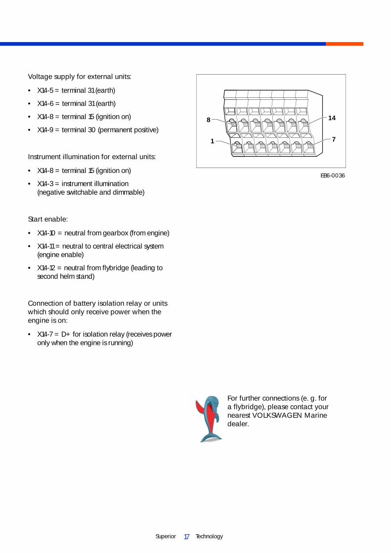
Voltage supply for external units:
• X14-5 = terminal 31 (earth)
• X14-6 = terminal 31 (earth)
• X14-8 = terminal 15 (ignition on)
• X14-9 = terminal 30 (permanent positive)
Instrument illumination for external units:
• X14-8 = terminal 15 (ignition on)
• X14-3 = instrument illumination (negative switchable and dimmable)
Start enable:
• X14-10 = neutral from gearbox (from engine)
• X14-11 = neutral to central electrical system (engine enable)
• X14-12 = neutral from flybridge (leading to second helm stand)
Connection of battery isolation relay or units which should only receive power when the engine is on:
• X14-7 = D+ for isolation relay (receives power only when the engine is running)
14
7
8
1
EB6-0036
For further connections (e. g. for a flybridge), please contact your nearest VOLKSWAGEN Marine dealer.

18Superior Technology
Electrical system
Overview of standard instrumentation installation (optionalAn installation template to be used as a cut-out for fitting the instrumentation, can be found on page 41.
The different connection alternatives for standard instrumentation are described from page 16.
EB6-0047
Legend
1. Instrument panel2. Connector to the engine central electrical
system (connection see page 19)

19Superior Technology
Engine connector
Connect the multiway connector of the main wiring harness to the central electrical system (connection -A-).
Note
Use the wiring harness tool, T 01906, to loosen and tighten the multiway connector.
Installing the instrument panel
An installation template for fitting the standard instrumentation, can be found on page 41.
Navigation instruments
To be able to use the advanced functions of the multifunction display in their entirety, the Volkswagen Marine instrumentation must be connected to a navigation instrument with a NMEA interface (e. g. GPS-receiver, LOG or similar).
* see also protocol NMEA 0183
Note
To configure the multifunction display please read the additional instruction manual for the multifunction display in the main instruction manual.
A
EB6-0032

20Superior Technology
Terminal strip -A- for the navigation instrument on the rear side of the instrument panel
• Terminal 5 = NMEA-B
• Terminal 6 = NMEA-A
Connection variants
Reverse gear unit with simple instrumentation:
Place a bridge between terminals 1 + 2 of the terminal strip.
Reverse gear unit with flybridge instrumentation:
Place a bridge between terminals 2 +3 of the terminal strip.
Z-drive with simple instrumentation:
Connect the throttle between terminals 1 + 2 of the terminal strip.
Z-drive with flybridge instrumentation:
Connect the throttle between terminals 2 +3 of the terminal strip for the flybridge instrumentation.
Electrical system
12
3
45
6A
EB5-0109

21Superior Technology
DIP switch on the rear side of the instrument panel:
Change the DIP switches -A- between "On" and "Off" positions to make the following settings:
1. Lighting bright/dark2. Lighting on/off3. Switch* off positionnot used off position
*Note:Switch in "Off" position for 4 + 5 cylinder engines / in "On" position for 6 cylinder engines.
Further connections on the rear side of the switch on the rear side of the instrument panel
-A- 22 pole terminal strip for the flybridge
-B- 22 pole terminal strip for the central electrical system
-C- 5 pole diagnosis terminal strip
12
3
45
6
A
A
C B
EB5-0110
EB5-0111

22Superior Technology
Installation dimensions for the 6 cylinder TDI VOLKSWAGEN Marine boat engine
Front view
Rear view
Engine installation dimensions
499
263 89
11+_
572 25+_
754
380
EB6-0011
547-597754
762
163-
185
EB6-0005
23Superior Technology
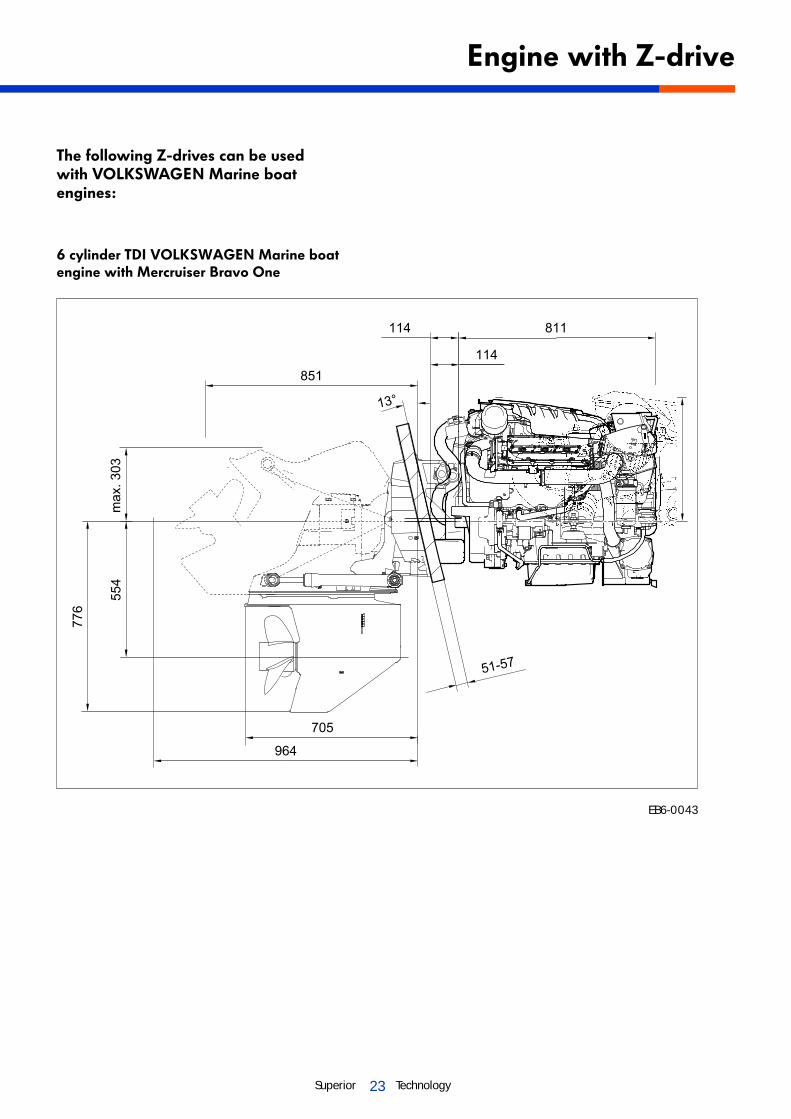
The following Z-drives can be used with VOLKSWAGEN Marine boat engines:
6 cylinder TDI VOLKSWAGEN Marine boat engine with Mercruiser Bravo One
Engine with Z-drive
EB6-0043

24Superior Technology
6 cylinder TDI VOLKSWAGEN Marine boat engine with Mercruiser Bravo Three
Engine with Z-drive dimensions
EB6-0044

25Superior Technology
The following reverse gear units can be used with VOLKSWAGEN Marine boat engines:
6 cylinder TDI VOLKSWAGEN Marine boat engine with reverse gear unit ZF 45A hydraulic 8°
Engine with reverse gear unit dimensions
EB6-0045

26Superior Technology
6 cylinder TDI VOLKSWAGEN Marine boat engine with reverse gear unit ZF 63A hydraulic 8°
Engine with reverse gear unit dimensions
EB6-0046

27Superior Technology
Cooling system
Introduction
To maintain the engine free from aggressive media such as salt water, Volkswagen Marine boat engines have a twin-circuit cooling system.
Engine cooling circuitThe internal engine cooling circuit is a closed system and is mixed with antifreeze (G12/G12+).
The seawater /freshwater circuit, also called the secondary circuit, is an open circuit in which the seawater / freshwater is sucked in and, after flowing through the main heat exchanger, fed back to the outside again via the exhaust system.
Sea water / fresh water circuitSeawater / freshwater is sucked in through an intake cap in the boat’s hull, downstream of which there is a seawater / freshwater valve.The seawater / freshwater filter filters dirt and impurities from the entering seawater / freshwater.
Aeration of the seawater / freshwater circuit using a ventilation unit
To prevent entry of seawater / freshwater into the exhaust system via the intake side of the seawater / freshwater circuit, a ventilation unit only has to be fitted if the engine is installed beneath the water line; (see figure on page 6, item number 3.; Overview of the exhaust system installation).
Explanation
If the cooling system is beneath the water line, then filling of the exhaust system with water may occur, if the boat remains stationary for some time. This is because the seawater / freshwater pump is not 100 % watertight and causes a siphon / suction effect in the coolant circuit. If this occurs, close the seawater / freshwater valve.
Connection for seawater/freshwater
Connect the seawater / freshwater hose -arrowed- to the seawater / freshwater pump -1-.
1
EB6-0029

28Superior Technology
Cooling circuit
Cooling system
21 3 4 5
6
7
8
910
11
12
13
14
15
17
18
19
20
21
16
Legend
1. Engine ventilation position2. Oil cooler3. Temperature switch 112 °C4. Temperature dual sender5. Left cylinder bank exhaust manifold6. Coolant expansion tank7. Engine8. External engine cooling circuit9. External heating supply connection10. External heating return connection11. Ventilation position
12. Servo / gearbox oil cooler13. Sea water / fresh water cooling circuit14. Main heat exchanger15. Sea water / fresh water 16. Sea water / fresh water filter17. Sea water / fresh water pump18. Intercooler19. Thermostat 70 °C20. Engine-side coolant pump21. Right cylinder bank exhaust manifold
EB6-0018

29Superior Technology
Overview of seawater / freshwater cooling installation
65
4321
EB6-0019
Legend
1. Water line2. Engine3. Sea water / fresh water filter
4. Sea water / fresh water valve5. Intake cap6. Seawater / freshwater connection
to the seawater / freshwater pump

30Superior Technology
Intake cap advice
• For motor boats, the sloping side of the intake mesh must point forwards. The fitting location of the intake cap should be as far as possible in the part of the boat shown hatched.In this case, the speed of the boat pushes the water inwards.
General
• Seawater / freshwater flows through the seawater / freshwater pump and then the main heat exchanger after first flowing through the seawater / freshwater filter.
• The intake hose from the seawater / freshwater filter to the seawater / freshwater pump must have a diameter of at least 45 mm. The hose should be as short as possible.
• In the main heat exchanger and the intercooler, the seawater / freshwater takes heat from the coolant circuit and thus provides additional engine cooling.
• Prior to over-wintering, the seawater / fresh-water must be drained via the drainage screws -1- and -2-.
Cooling system
EB5-0017
The measures required for over-wintering the VOLKSWAGEN Marine boat engine are described in your VOLKSWAGEN Marine boat engine instruction manual.
1
2
EB6-0033

31Superior Technology
Fuel system
Introduction
The fuel system comprises a number of components. These components (fuel tank, circulation prefilter with water separator etc.) must be impeccably clean and should be fitted with extreme care.
Dirt and impurities could cause incorrect engine operation. After installing the fuel system, check for leaks, to ensure optimum protection against fire risk.
Functional description of the fuel system
EB6-0020
Please observe the instructions on the following page!
Legend
1. Fine fuel filter with water monitor2. Manual pump3. Pressure maintenance valve4. High pressure accumulator (rail)
5. Piezo injector6. High pressure pump with valve for fuel dosing
(N290)7. Circulation prefilter with water separator8. Fuel tank9. Bleed screw

32Superior Technology
Fuel system
Requirements:
• The compartment containing the fuel system must be sufficiently ventilated. Fuel tank and filler cap must have an earth connection to the battery (for steel boats to the hull).
• When arranging the components, ensure that there is sufficient clearance for any future maintenance and repair work.
• A fuel return line is to be routed from the fuel tank to the fuel fine filter. The line cross section must be at least 8 mm.
• A fuel return line is to be routed to the fuel tank. The line cross section must be at least 8 mm.
Engine fuel system overview
The fuel system is divided into 3 pressure areas:
1 - Supply and return pressure
2 - Return pressure between injectors and pressure maintenance valve
3 - High pressure
In the fuel supply, fuel is taken from the mechanical gear pump from the fuel tank via the fuel fine filter to the high pressure pump. Here the high fuel pressure required for injection is created and supplied to the high pressure accumulator (rail).
From the high pressure accumulator, the fuel is transported to the injectors, from where it is injected into the combustion chamber.
The pressure maintenance valve maintains the return pressure of the injectors at 10 bar. This pressure is required for the correct functioning of the piezo-injectors.

33Superior Technology
Connection for the fuel supply line
Connect the fuel supply line to connection -2- of the fuel fine filter -1-.
Bleeding the fuel line of the boat
The fuel line must be properly bled before the engine is put into operation.Open the bleed screw -9- (see figure EB6-0020 on page 31) and work the hand pump until fuel comes out of the bleed screw port.Then close the bleed screw.
Connection for the fuel return line
Connect the fuel return line to connection -1- on the high pressure accumulator (rail) (cylinder bank 2) -2-.
2
1
21
EB6-0023
EB6-0027

34Superior Technology
Introduction
Engine compartment ventilation
• The engine must be supplied with air (oxygen), to ensure optimum fuel combustion.
• The engine must be sufficiently ventilated to ensure that the temperature can be maintained at an optimum value, that is as low as possible.(ΔTmax. above ambient temperature: 10 °C to 15 °C).
• To ensure optimum engine compartment ventilation, the air inlet should be placed where the sucked-in air is as clean as possible and where the engine's own exhaust gases cannot be sucked in.
• Water must not be able to enter either the air inlet or the air outlet.
• The hydraulic cross section for the air inlet must be at least 200 cm2.
• If other equipment that requires oxygen for its operation (e.g. an auxiliary heater) is located in the engine compartment, then this must also be considered when dimensioning the air inlet.

35Superior Technology
Front view
Engine components list
1
2
3
4
5678
9
10
11
12
EB6-0030
Legend
1. Hydraulic oil reservoir2. Coolant expansion tank3. Intercooler4. Sacrificial anode5. Connection for seawater/freshwater6. Sea water / fresh water pump
7. Main heat exchanger8. Engine oil drainage hose9. Oil extraction pump10. Alternator11. Central electrical system12. Dipstick

36Superior Technology
View of starter side
Engine components list
5
1
2
3
4
7
6
8
Legend
1. Button for oil extractor pump2. Housing for central electrical system and
shifting bracket (Mercruiser shifting bracket)3. Connection for the fuel supply line4. Fine fuel filter with water monitor
5. Oil sump6. Starter7. Air filter element8. Turbocharger
EB6-0031

37Superior Technology
View of gearbox side
EB6-0042
Legend
1. Cover2. Exhaust pipe connection3. Transmission bell housing4. Hydraulic connection5. Servo / gearbox oil cooler
6. Speed sender connection7. Gearbox neutral switch connection8. Optional accessory connection (e. g. boiler kit)9. Hydraulic pump10. Throttle lever position sender

38Superior Technology
Engine description
Engine codeTDI 225-6 BSP
Engine codeTDI 265-6 CEZ
Cubic capacity cm3 2967
Bore/stroke mm 83/91.4
Compression ratio 19.5:1
Ignition sequence 3-6-1-4-2-5
Power output(as per ISO 3046 with marine control unit)
TDI 225-6 at 4200 rpm kW165
TDI 265-6 at 4200 rpm kW195
Charge air pressure(at rated power output and under standardized operating conditions)
TDI 225-6 at 4200 rpm bar 1.25
TDI 265-6 at 4200 rpm bar 1.50
Weight
TDI 225-6 kg approx. 330
TDI 265-6 kg approx. 330
Maximum inclination during operation
15° in all directions
30° for short periods
<) °
Permissible engine operating data
Permissible engine temperature
Maximum permissible °C (°F) 135 (275)temperature in the oil sump
Permissible coolant temperature
Maximum permissible °C (°F) 105 (221)temperature at the outlet from the engine duringcontinuous operation
Engine electrical equipment
12 V alternator A 180
Starter 12 V kW 2.0
Battery 12 V A (Ah) 420 (88)minimum capacity
Diameters / Line cross sections
Exhaust system Ø 100 mm
Intake hose for sea water / freshwater Ø 45 mm
Fuel lines Ø 8 mm
Battery connection cable 35 mm2
Technical Data
39Superior Technology
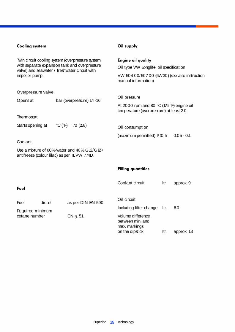
Cooling system
Twin circuit cooling system (overpressure system with separate expansion tank and overpressure valve) and seawater / freshwater circuit with impeller pump.
Overpressure valve
Opens at bar (overpressure) 1.4 -1.6
Thermostat
Starts opening at °C (°F) 70 (158)
Coolant
Use a mixture of 60% water and 40% G12/G12+ antifreeze (colour lilac) as per TL VW 774D.
Fuel
Fuel diesel as per DIN EN 590
Required minimumcetane number CN > 51
Oil supply
Engine oil quality
Oil type VW Longlife, oil specification
VW 504 00/507 00 (5W30) (see also instruction manual information)
Oil pressure
At 2000 rpm and 80 °C (176 °F) engine oil temperature (overpressure) at least 2.0
Oil consumption
(maximum permitted) l/10 h 0.05 - 0.1
Filling quantities
Coolant circuit ltr. approx. 9
Oil circuit
Including filter change ltr. 6.0
Volume differencebetween min. andmax. markings on the dipstick ltr. approx. 1.3

40Superior Technology
Circular cut-out for round instruments in mm:
Rev. counter Ø 85
Voltmeter Ø 52
Water temperature indicator Ø 52
Ignition lock Ø 26
Installation template for the control unit
Installation dimensions for customized
130
123
70
65
63
EB6-0037

41Superior Technology
Installation template for standard instrumentation
95
=176
=
190
=121=
135
EB5-0113

42Superior Technology

43Superior Technology

Installation description EB06
© 2007 VOLKSWAGEN Marine
Text, figures and standards in this guide are based on information current at the time of printing. Reprinting, reproduction or translation, in whole or in part, is not permitted without the written approval of VOLKSWAGEN Marine. All rights according to the applicable copyright laws are expressly reserved for VOLKSWAGEN Marine. Subject to alterations.Copy date 11/07
Postfach 31 11 76, 38231 SalzgitterEdition 11/07 print number 066.991.EB06.20
This paper was produced from wood pulp bleached without chlorine.


