Data sheet
BMP183 Digital pressure sensor
BMP183 Data sheet
Document revision 1.0
Document release date June 13th, 2012
Document number BST-BMP183-DS000-00
Technical reference code(s) 0 273 300 357
Notes Data in this document are subject to change without notice. Product photos and pictures are for illustration purposes only and may differ from the real product‟s appearance.
Bosch Sensortec

Data sheet
BMP183
Page 2
BST-BMP183-DS000-00 | Revision 1.0 | June 2012 Bosch Sensortec
© Bosch Sensortec GmbH reserves all rights even in the event of industrial property rights. We reserve all rights of disposal such as copying and passing on to third
parties. BOSCH and the symbol are registered trademarks of Robert Bosch GmbH, Germany.
Note: Specifications within this document are subject to change without notice.
BMP183
DIGITAL PRESSURE SENSOR
Key features
Pressure range: 300 ... 1100hPa (+9000m ... -500m relating to sea level) Supply voltage: 1.8 ... 3.6V (VDD) 1.62V ... 3.6V (VDDIO) Package: LGA package with metal lid Small footprint: 3.6mm x 3.8mm Super-flat: 0.93mm height Low power: 5µA at 1 sample / sec. in standard mode Low noise: 0.06hPa (0.5m) in ultra low power mode 0.02hPa (0.17m) ultra high resolution mode - Temperature measurement included - SPI interface - Fully calibrated - Pb-free, halogen-free and RoHS compliant, - MSL 1
Typical applications
Enhancement of GPS navigation (dead-reckoning, slope detection, etc.)
In- and out-door navigation
Leisure and sports
Weather forecast
Vertical velocity indication (rise/sink speed)

Data sheet
BMP183
Page 3
BST-BMP183-DS000-00 | Revision 1.0 | June 2012 Bosch Sensortec
© Bosch Sensortec GmbH reserves all rights even in the event of industrial property rights. We reserve all rights of disposal such as copying and passing on to third
parties. BOSCH and the symbol are registered trademarks of Robert Bosch GmbH, Germany.
Note: Specifications within this document are subject to change without notice.
BMP183 general description
The BMP183 is the function compatible successor of the BMP085, a new generation of high
precision digital pressure sensors for consumer applications.
The ultra-low power, low voltage electronics of the BMP183 is optimized for use in mobile phones,
PDAs, GPS navigation devices and outdoor equipment. With a low altitude noise of merely 0.25m at
fast conversion time, the BMP183 offers superior performance. The SPI interface allows for easy
system integration with a microcontroller.
The BMP183 is based on piezo-resistive technology for EMC robustness, high accuracy and linearity as
well as long term stability.
Robert Bosch is the world market leader for pressure sensors in automotive applications. Based on
the experience of over 400 million pressure sensors in the field, the BMP183 continues a new
generation of micro-machined pressure sensors.
Data sheet
BMP183
Page 4
BST-BMP183-DS000-00 | Revision 1.0 | June 2012 Bosch Sensortec
© Bosch Sensortec GmbH reserves all rights even in the event of industrial property rights. We reserve all rights of disposal such as copying and passing on to third
parties. BOSCH and the symbol are registered trademarks of Robert Bosch GmbH, Germany.
Note: Specifications within this document are subject to change without notice.
Index of Contents
1. ELECTRICAL CHARACTERISTICS ................................................................................................. 6
2. ABSOLUTE MAXIMUM RATINGS .................................................................................................... 8
3. OPERATION ...................................................................................................................................... 9
3.1 POWER SUPPLY AND POWER ON SEQUENCE ................................................................................. 9
3.2 GENERAL DESCRIPTION .............................................................................................................. 9
3.3 GENERAL FUNCTION AND APPLICATION SCHEMATICS ..................................................................... 9
3.4 MEASUREMENT OF PRESSURE AND TEMPERATURE ..................................................................... 11
3.4.1 Hardware pressure sampling accuracy modes ................................................................ 12
3.4.2 Software pressure sampling accuracy modes .................................................................. 13 3.5 CALIBRATION COEFFICIENTS ...................................................................................................... 13
3.6 CALCULATING PRESSURE AND TEMPERATURE ............................................................................ 14
3.7 CALCULATING ABSOLUTE ALTITUDE ............................................................................................ 16
3.8 CALCULATING PRESSURE AT SEA LEVEL ..................................................................................... 17
4. GLOBAL MEMORY MAP ................................................................................................................ 18
5. SPI INTERFACE .............................................................................................................................. 19
5.1 SPI SPECIFICATION ................................................................................................................... 19
5.2 SPI PROTOCOL......................................................................................................................... 20
5.3 START TEMPERATURE AND PRESSURE MEASUREMENT ................................................................ 21
5.4 READ A/D CONVERSION RESULT OR NMV DATA ......................................................................... 22
6. PACKAGE ........................................................................................................................................ 23
6.1 PIN CONFIGURATION ................................................................................................................. 23
6.2 OUTLINE DIMENSIONS ............................................................................................................... 24
6.2.1 Bottom view ..................................................................................................................... 24
6.2.2 Top view .......................................................................................................................... 25
6.2.3 Side view ......................................................................................................................... 25 6.3 MOISTURE SENSITIVITY LEVEL AND SOLDERING ........................................................................... 26
6.4 ROHS COMPLIANCY .................................................................................................................. 26
6.5 MOUNTING AND ASSEMBLY RECOMMENDATIONS ......................................................................... 26
7. LEGAL DISCLAIMER ...................................................................................................................... 27

Data sheet
BMP183
Page 5
BST-BMP183-DS000-00 | Revision 1.0 | June 2012 Bosch Sensortec
© Bosch Sensortec GmbH reserves all rights even in the event of industrial property rights. We reserve all rights of disposal such as copying and passing on to third
parties. BOSCH and the symbol are registered trademarks of Robert Bosch GmbH, Germany.
Note: Specifications within this document are subject to change without notice.
7.1 ENGINEERING SAMPLES ............................................................................................................ 27
7.2 PRODUCT USE .......................................................................................................................... 27
7.3 APPLICATION EXAMPLES AND HINTS ........................................................................................... 27
8. DOCUMENT HISTORY AND MODIFICATION ............................................................................... 28

Data sheet
BMP183
Page 6
BST-BMP183-DS000-00 | Revision 1.0 | June 2012 Bosch Sensortec
© Bosch Sensortec GmbH reserves all rights even in the event of industrial property rights. We reserve all rights of disposal such as copying and passing on to third
parties. BOSCH and the symbol are registered trademarks of Robert Bosch GmbH, Germany.
Note: Specifications within this document are subject to change without notice.
1. Electrical characteristics
If not stated otherwise, the given values are ±3-Sigma values over temperature/voltage range in the
given operation mode. All values represent the new parts specification; additional solder drift is
shown separately.
Table 1: Operating conditions, output signal and mechanical characteristics
Parameter Symbol Condition Min Typ Max Units
Operating temperature TA
operational -40 +85 °C
full accuracy 0 +65
Supply voltage VDD ripple max. 50mVpp 1.8 2.5 3.6 V
VDDIO 1.62 2.5 3.6 V
Supply current @ 1 sample / sec.
25°C
IDDLOW ultra low power mode 3 µA
IDDSTD standard mode 5 µA
IDDHR high resolution mode 7 µA
IDDUHR Ultra high res. mode 12 µA
IDDAR Advanced res. mode 32 µA
Peak current Ipeak during conversion 650 1000 µA
Standby current IDDSBM @ 25°C 0.1 µA
Relative accuracy pressure
VDD = 3.3V
950 . . . 1050 hPa
@ 25 °C
±0.12 hPa
±1.0 m
700 … 900hPa 25 . . . 40 °C
±0.12 hPa
±1.0 m
Absolute accuracy pressure
VDD = 3.3V
300 . . . 1100 hPa
0 . . . +65 °C -4.0 -1.0
(1) +2.0 hPa
300 . . . 1100 hPa
-20 . . . 0 °C -6.0 -1.0
(1) +4.5 hPa
Resolution of output data
pressure 0.01 hPa
temperature 0.1 °C
Noise in pressure see table on page 12-13
(1)
The typical value is: -1±1

Data sheet
BMP183
Page 7
BST-BMP183-DS000-00 | Revision 1.0 | June 2012 Bosch Sensortec
© Bosch Sensortec GmbH reserves all rights even in the event of industrial property rights. We reserve all rights of disposal such as copying and passing on to third
parties. BOSCH and the symbol are registered trademarks of Robert Bosch GmbH, Germany.
Note: Specifications within this document are subject to change without notice.
Absolute accuracy temperature VDD = 3.3V
@ 25 °C -1.5 ±0.5 +1.5 °C
0 . . . +65 °C -2.0 ±1.0 +2.0 °C
Conversion time pressure
tc_p_low ultra low power mode 3 4.5 ms
tc_p_std standard mode 5 7.5 ms
tc_p_hr high resolution mode 9 13.5 ms
tc_p_luhr ultra high res. mode 17 25.5 ms
tc_p_ar Advanced res. mode 51 76.5 ms
Conversion time temperature
tC_temp standard mode 3 4.5 ms
Serial data clock fSCL 3.4 MHz
Solder drifts2
Minimum solder height 50µm
-0.5 +2 hPa
Long term stability3 12 months ±1.0 hPa
2 verified with BST customer shuttle boards
3 Long term stability is specified in the full accuracy operating pressure range 0 … 65°C
Data sheet
BMP183
Page 8
BST-BMP183-DS000-00 | Revision 1.0 | June 2012 Bosch Sensortec
© Bosch Sensortec GmbH reserves all rights even in the event of industrial property rights. We reserve all rights of disposal such as copying and passing on to third
parties. BOSCH and the symbol are registered trademarks of Robert Bosch GmbH, Germany.
Note: Specifications within this document are subject to change without notice.
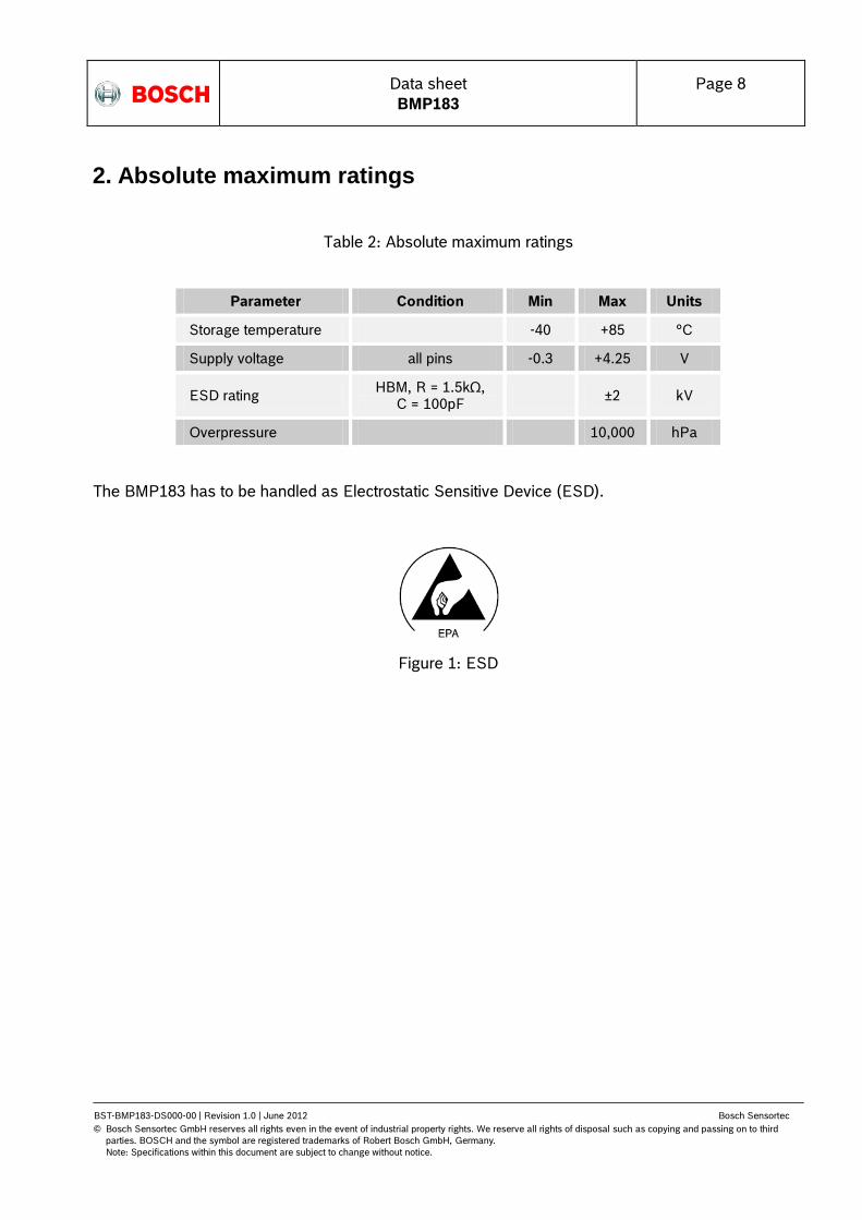
2. Absolute maximum ratings
Table 2: Absolute maximum ratings
Parameter Condition Min Max Units
Storage temperature -40 +85 °C
Supply voltage all pins -0.3 +4.25 V
ESD rating HBM, R = 1.5kΩ,
C = 100pF ±2 kV
Overpressure 10,000 hPa
The BMP183 has to be handled as Electrostatic Sensitive Device (ESD).
Figure 1: ESD
Data sheet
BMP183
Page 9
BST-BMP183-DS000-00 | Revision 1.0 | June 2012 Bosch Sensortec
© Bosch Sensortec GmbH reserves all rights even in the event of industrial property rights. We reserve all rights of disposal such as copying and passing on to third
parties. BOSCH and the symbol are registered trademarks of Robert Bosch GmbH, Germany.
Note: Specifications within this document are subject to change without notice.
3. Operation
3.1 Power supply and power on sequence
The BMP183 has two distinct power supply pins: VDD and VDDIO. VDD powers the internal digital
and analogue circuitry and should not suffer from large voltage spikes. VDDIO is the supply for the
digital interface and must match the voltages on the SPI interface. In case the voltage range allows it,
VDD and VDDIO can be fed from a single supply line which must be >1.8V.
The preferred power on sequence is VDD first. Even though VDDIO can be powered on before VDD,
there is a chance of excessive power consumption (a few mA) if this sequence is used, and the state
of the output pins is undefined so that the bus can be locked. Therefore, VDD must be powered
before VDDIO unless the limitations above are understood and not critical.
3.2 General description
The BMP183 is designed to be connected directly to a microcontroller of a mobile device via the SPI
bus. The pressure and temperature data has to be compensated by the calibration data of the
E2PROM of the BMP183.
3.3 General function and application schematics
The BMP183 consists of a piezo-resistive sensor, an analog to digital converter and a control unit
with E2PROM and a SPI interface. The BMP183 delivers the uncompensated value of pressure and
temperature. The E2PROM has stored 176 bit of individual calibration data. This is used to
compensate offset, temperature dependence and other parameters of the sensor.
UP = pressure data (16 to 19 bit) UT = temperature data (16 bit)
Data sheet
BMP183
Page 10
BST-BMP183-DS000-00 | Revision 1.0 | June 2012 Bosch Sensortec
© Bosch Sensortec GmbH reserves all rights even in the event of industrial property rights. We reserve all rights of disposal such as copying and passing on to third
parties. BOSCH and the symbol are registered trademarks of Robert Bosch GmbH, Germany.
Note: Specifications within this document are subject to change without notice.
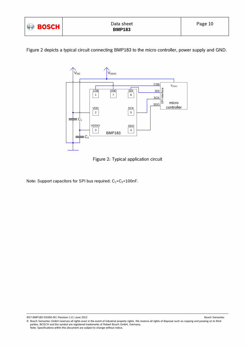
Figure 2 depicts a typical circuit connecting BMP183 to the micro controller, power supply and GND.
Figure 2: Typical application circuit
Note: Support capacitors for SPI bus required: C1=C2=100nF.
CSB
SDI
SCK
SDO
BMP183
1 67
4
2 5
3
C2
VDDIOVDD
C1
micro
controller
VDDIO
SP
I in
terf
ace
CSB SDI
SCK
SDO
GND
VDD
VDDIO
Data sheet
BMP183
Page 11
BST-BMP183-DS000-00 | Revision 1.0 | June 2012 Bosch Sensortec
© Bosch Sensortec GmbH reserves all rights even in the event of industrial property rights. We reserve all rights of disposal such as copying and passing on to third
parties. BOSCH and the symbol are registered trademarks of Robert Bosch GmbH, Germany.
Note: Specifications within this document are subject to change without notice.
Start temperature measurement
Read UT
Start pressure measurement
Read UP
Start
calculate pressure and temperature in physical
units
wait (depends on mode, see below)
wait 4.5 ms
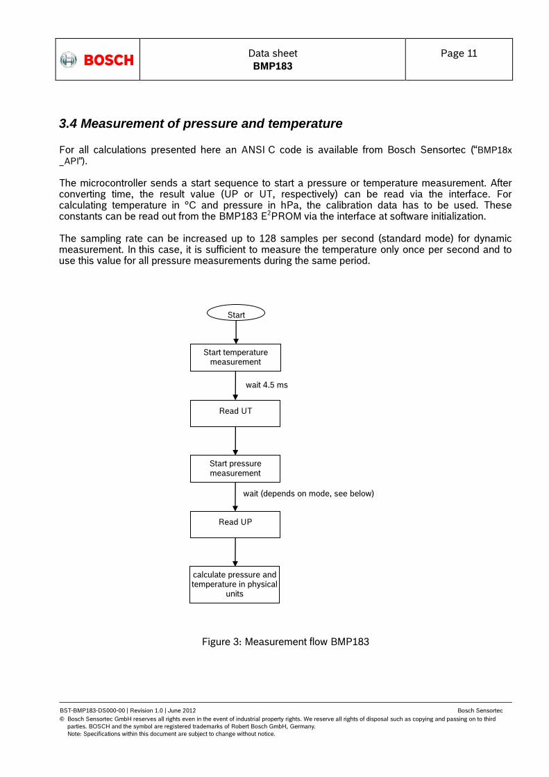
3.4 Measurement of pressure and temperature For all calculations presented here an ANSI C code is available from Bosch Sensortec (“BMP18x
_API”). The microcontroller sends a start sequence to start a pressure or temperature measurement. After converting time, the result value (UP or UT, respectively) can be read via the interface. For calculating temperature in °C and pressure in hPa, the calibration data has to be used. These constants can be read out from the BMP183 E2PROM via the interface at software initialization. The sampling rate can be increased up to 128 samples per second (standard mode) for dynamic measurement. In this case, it is sufficient to measure the temperature only once per second and to use this value for all pressure measurements during the same period.
Figure 3: Measurement flow BMP183
Data sheet
BMP183
Page 12
BST-BMP183-DS000-00 | Revision 1.0 | June 2012 Bosch Sensortec
© Bosch Sensortec GmbH reserves all rights even in the event of industrial property rights. We reserve all rights of disposal such as copying and passing on to third
parties. BOSCH and the symbol are registered trademarks of Robert Bosch GmbH, Germany.
Note: Specifications within this document are subject to change without notice.
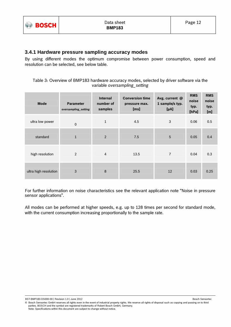
3.4.1 Hardware pressure sampling accuracy modes
By using different modes the optimum compromise between power consumption, speed and
resolution can be selected, see below table.
Table 3: Overview of BMP183 hardware accuracy modes, selected by driver software via the variable oversampling_setting
Mode
Parameter
oversampling_setting
Internal
number of
samples
Conversion time
pressure max.
[ms]
Avg. current @
1 sample/s typ.
[µA]
RMS
noise
typ.
[hPa]
RMS
noise
typ.
[m]
ultra low power
0 1 4.5 3 0.06 0.5
standard
1
2 7.5 5 0.05 0.4
high resolution
2
4 13.5 7 0.04 0.3
ultra high resolution
3
8 25.5 12 0.03 0.25
For further information on noise characteristics see the relevant application note “Noise in pressure sensor applications”.
All modes can be performed at higher speeds, e.g. up to 128 times per second for standard mode,
with the current consumption increasing proportionally to the sample rate.

Data sheet
BMP183
Page 13
BST-BMP183-DS000-00 | Revision 1.0 | June 2012 Bosch Sensortec
© Bosch Sensortec GmbH reserves all rights even in the event of industrial property rights. We reserve all rights of disposal such as copying and passing on to third
parties. BOSCH and the symbol are registered trademarks of Robert Bosch GmbH, Germany.
Note: Specifications within this document are subject to change without notice.
3.4.2 Software pressure sampling accuracy modes
For applications where a low noise level is critical, averaging is recommended if the lower bandwidth
is acceptable. Oversampling can be enabled using the software API driver (with OSR = 3).
Table 4: Overview of BMP183 software accuracy mode, selected by driver software via the variable software_oversampling_setting
Mode
Parameter
oversampling_setting
software_
oversampl
ing_settin
g
Conversion
time
pressure
max. [ms]
Avg. current
@ 1
sample/s
typ. [µA]
RMS noise
typ. [hPa]
RMS noise
typ. [m]
Advanced
resolution
3 1 76.5 32 0.02 0.17
3.5 Calibration coefficients
The 176 bit E2PROM is partitioned in 11 words of 16 bit each. These contain 11 calibration
coefficients. Every sensor module has individual coefficients. Before the first calculation of
temperature and pressure, the master reads out the E2PROM data.
The data communication can be checked by checking that none of the words has the value 0 or
0xFFFF.
Table 5: Calibration coefficients
BMP183 reg adr
Parameter MSB LSB
AC1 0xAA 0xAB
AC2 0xAC 0xAD
AC3 0xAE 0xAF
AC4 0xB0 0xB1
AC5 0xB2 0xB3
AC6 0xB4 0xB5
B1 0xB6 0xB7
B2 0xB8 0xB9
MB 0xBA 0xBB
MC 0xBC 0xBD
MD 0xBE 0xBF
Data sheet
BMP183
Page 14
BST-BMP183-DS000-00 | Revision 1.0 | June 2012 Bosch Sensortec
© Bosch Sensortec GmbH reserves all rights even in the event of industrial property rights. We reserve all rights of disposal such as copying and passing on to third
parties. BOSCH and the symbol are registered trademarks of Robert Bosch GmbH, Germany.
Note: Specifications within this document are subject to change without notice.
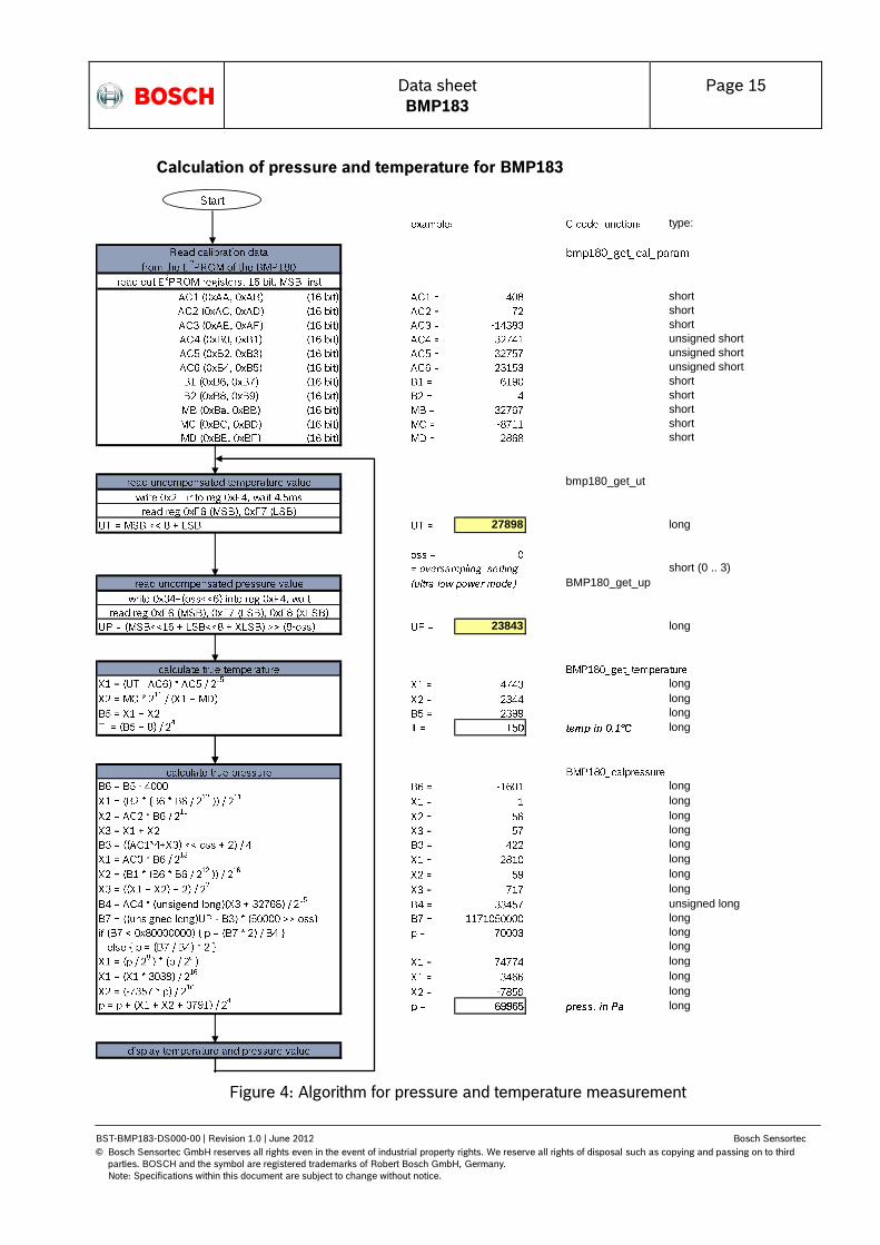
3.6 Calculating pressure and temperature
The mode (ultra low power, standard, high, ultra high resolution) can be selected by the variable
oversampling_setting (0, 1, 2, 3) in the C code.
Calculation of true temperature and pressure in steps of 1Pa (= 0.01hPa = 0.01mbar) and
temperature in steps of 0.1°C.
The following figure shows the detailed algorithm for pressure and temperature measurement.
This algorithm is available to customers as reference C source code (“BMP18x_API”) from Bosch
Sensortec and via its sales and distribution partners. Please contact your Bosch Sensortec
representative for details.
Data sheet
BMP183
Page 15
BST-BMP183-DS000-00 | Revision 1.0 | June 2012 Bosch Sensortec
© Bosch Sensortec GmbH reserves all rights even in the event of industrial property rights. We reserve all rights of disposal such as copying and passing on to third
parties. BOSCH and the symbol are registered trademarks of Robert Bosch GmbH, Germany.
Note: Specifications within this document are subject to change without notice.
Figure 4: Algorithm for pressure and temperature measurement
Calculation of pressure and temperature for BMP183
type:
short
short
short
unsigned short
unsigned short
unsigned short
short
short
short
short
short
bmp180_get_ut
27898 long
short (0 .. 3)
BMP180_get_up
23843 long
long
long
long
long
long
long
long
long
long
long
long
long
unsigned long
long
long
long
long
long
long
long
Data sheet
BMP183
Page 16
BST-BMP183-DS000-00 | Revision 1.0 | June 2012 Bosch Sensortec
© Bosch Sensortec GmbH reserves all rights even in the event of industrial property rights. We reserve all rights of disposal such as copying and passing on to third
parties. BOSCH and the symbol are registered trademarks of Robert Bosch GmbH, Germany.
Note: Specifications within this document are subject to change without notice.
-1000
0
1000
2000
3000
4000
5000
6000
7000
8000
9000
300
400
500
600
700
800
900
1000
1100
Barometric pressure [hPa]
Alt
itu
de
ab
ov
e s
ea
le
ve
l [m
]
Altitude in standard
atmosphere
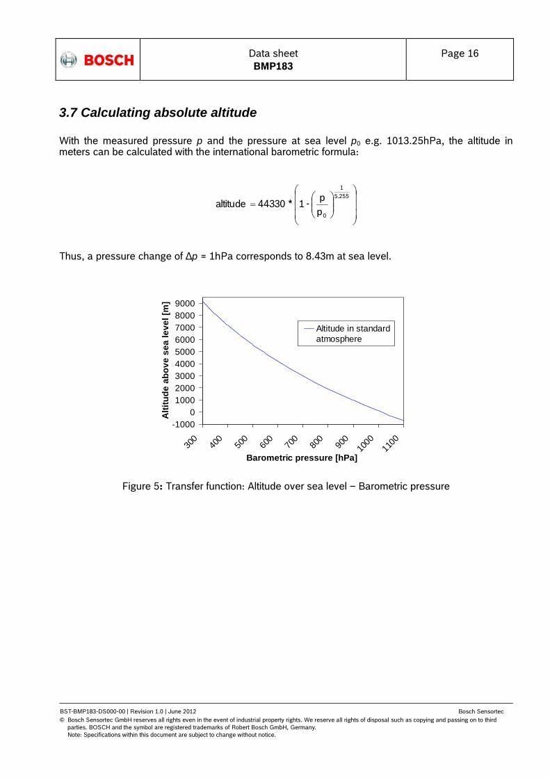
3.7 Calculating absolute altitude
With the measured pressure p and the pressure at sea level p0 e.g. 1013.25hPa, the altitude in meters can be calculated with the international barometric formula:
Thus, a pressure change of ∆p = 1hPa corresponds to 8.43m at sea level.
Figure 5: Transfer function: Altitude over sea level – Barometric pressure
5.255
1
0p
p -1 * 44330 altitude

Data sheet
BMP183
Page 17
BST-BMP183-DS000-00 | Revision 1.0 | June 2012 Bosch Sensortec
© Bosch Sensortec GmbH reserves all rights even in the event of industrial property rights. We reserve all rights of disposal such as copying and passing on to third
parties. BOSCH and the symbol are registered trademarks of Robert Bosch GmbH, Germany.
Note: Specifications within this document are subject to change without notice.
3.8 Calculating pressure at sea level
With the measured pressure p and the absolute altitude the pressure at sea level can be calculated:
Thus, a difference in altitude of ∆altitude = 10m corresponds to 1.2hPa pressure change at sea level.
255.50
44330
altitude - 1
p p

Data sheet
BMP183
Page 18
BST-BMP183-DS000-00 | Revision 1.0 | June 2012 Bosch Sensortec
© Bosch Sensortec GmbH reserves all rights even in the event of industrial property rights. We reserve all rights of disposal such as copying and passing on to third
parties. BOSCH and the symbol are registered trademarks of Robert Bosch GmbH, Germany.
Note: Specifications within this document are subject to change without notice.
4. Global Memory Map
The memory map below shows all externally accessible data registers which are needed to operate
BMP183. The left columns show the memory addresses. The columns in the middle depict the
content of each register bit. The colors of the bits indicate whether they are read-only, write-only or
read- and writable. The memory is volatile so that the writable content has to be re-written after each
power-on.
Not all register addresses are shown. These registers are reserved for further Bosch factory testing
and trimming.
Figure 6: Memory map
Measurement control (register F4h <4:0>): Controls measurements. Refer to Figure 6 for usage
details.
Sco (register F4h <5>): Start of conversion. The value of this bit stays “1” during conversion and is
reset to “0” after conversion is complete (data registers are filled).
Oss (register F4h <7:6>): controls the oversampling ratio of the pressure measurement (00b: single,
01b: 2 times, 10b: 4 times, 11b: 8 times).
Soft reset (register E0h): Write only register. If set to 0xB6, will perform the same sequence as
power on reset.
Chip-id (register D0h): This value is fixed to 0x55 and can be used to check whether
communication is functioning.
After conversion, data registers can be read out in any sequence (i.e. MSB first or LSB first). Using a
burst read is not mandatory.
Register Name Register Adress bit7 bit6 bit5 bit4 bit3 bit2 bit1 bit0 Reset state
out_xlsb F8h 0 0 0 00h
out_lsb F7h 00h
out_msb F6h 80h
ctrl_meas F4h sco 00h
soft reset E0h 00h
id D0h 55h
calib21 downto calib0 BFh down to AAh n/a
Registers: Control
registers
Calibration
registers
Data
registers Fixed
Type: read / write read only read only read only
calib21<7:0> down to calib0<7:0>
adc_out_xlsb<7:3>
reset
id<7:0>
adc_out_lsb<7:0>
adc_out_msb<7:0>
oss<1:0> measurement control

Data sheet
BMP183
Page 19
BST-BMP183-DS000-00 | Revision 1.0 | June 2012 Bosch Sensortec
© Bosch Sensortec GmbH reserves all rights even in the event of industrial property rights. We reserve all rights of disposal such as copying and passing on to third
parties. BOSCH and the symbol are registered trademarks of Robert Bosch GmbH, Germany.
Note: Specifications within this document are subject to change without notice.
5. SPI Interface The BMP183 features a four wire SPI interface with clock speeds of up to 10 MHz. The interface is four wire SPI with CPOL = 1, CPHA = 1 (SPI mode 3).
The SPI bus is used to control the sensor, to read calibration data from the E2PROM and to read the
measurement data when A/D conversion is finished.
5.1 SPI specification
Table 6: Electrical parameters for the SPI interface
Parameter Symbol Min. Typ Max. Units
Clock input frequency fSCL 0.0 10.0 MHz
Input-low level VIL 0 0.2 * VDDIO V
Input-high level VIH 0.8 * VDDIO VDDIO V
SCK low pulse Tlow_sck4 20 ns
SCK high pulse Thigh_sck_4 20 ns
SDI setup time Tsetup_sdi_4 20 ns
SDI hold time Thold_sdi_4 20 ns
SDO output delay Tdelay_sdo_4 30 ns
CSB setup time Tsetup_csb_4 20 ns
CSB hold time Thold_csb_4 20 ns
Start-up time after power-up, before first communication
tStart 10 ms

Data sheet
BMP183
Page 20
BST-BMP183-DS000-00 | Revision 1.0 | June 2012 Bosch Sensortec
© Bosch Sensortec GmbH reserves all rights even in the event of industrial property rights. We reserve all rights of disposal such as copying and passing on to third
parties. BOSCH and the symbol are registered trademarks of Robert Bosch GmbH, Germany.
Note: Specifications within this document are subject to change without notice.
5.2 SPI protocol
CSB is active low with pull-up resistor integrated. Data on SDI is latched by BMP183 at SCK
rising edge and SDO is changed at SCK falling edge. Communication starts when CSB goes to low
and stops when CSB goes to high; during these transitions on CSB, SCK must be high.
In the SPI protocol, the MSB of the register address remains is not used. For example, register 0xF7
is addressed by 0x77 in SPI mode. Bit 7 is replaced by an R/W bit (read: „1‟, write: „0‟).
Figure 7: SPI protocol
When write is required, sequences of two bytes are required: one control byte to define the address
to be written to and one data byte which is written:
Figure 8: SPI write of two bytes
When read is required, the sequence consists in one control byte to define the first address to be read followed by data bytes. Addresses are automatically incremented.
Figure 9: SPI read of two bytes
Data sheet
BMP183
Page 21
BST-BMP183-DS000-00 | Revision 1.0 | June 2012 Bosch Sensortec
© Bosch Sensortec GmbH reserves all rights even in the event of industrial property rights. We reserve all rights of disposal such as copying and passing on to third
parties. BOSCH and the symbol are registered trademarks of Robert Bosch GmbH, Germany.
Note: Specifications within this document are subject to change without notice.
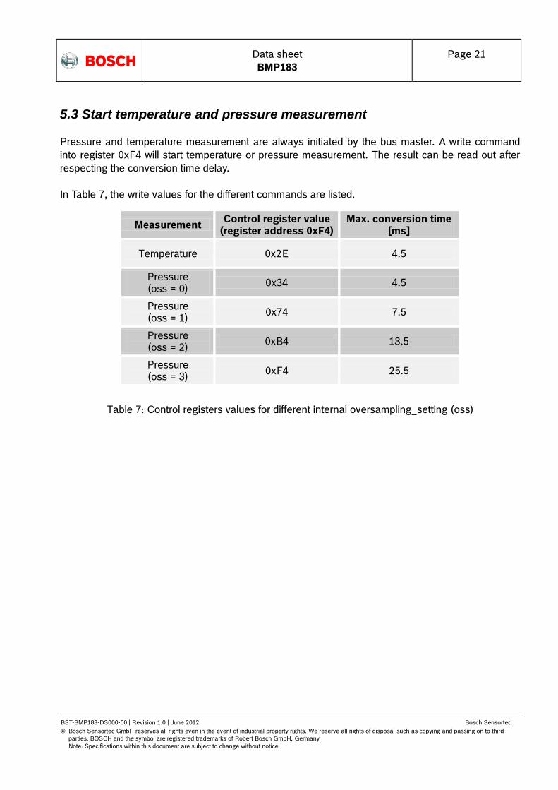
5.3 Start temperature and pressure measurement
Pressure and temperature measurement are always initiated by the bus master. A write command
into register 0xF4 will start temperature or pressure measurement. The result can be read out after
respecting the conversion time delay.
In Table 7, the write values for the different commands are listed.
Table 7: Control registers values for different internal oversampling_setting (oss)
Measurement Control register value
(register address 0xF4) Max. conversion time
[ms]
Temperature 0x2E 4.5
Pressure (oss = 0)
0x34 4.5
Pressure (oss = 1)
0x74 7.5
Pressure (oss = 2)
0xB4 13.5
Pressure (oss = 3)
0xF4 25.5

Data sheet
BMP183
Page 22
BST-BMP183-DS000-00 | Revision 1.0 | June 2012 Bosch Sensortec
© Bosch Sensortec GmbH reserves all rights even in the event of industrial property rights. We reserve all rights of disposal such as copying and passing on to third
parties. BOSCH and the symbol are registered trademarks of Robert Bosch GmbH, Germany.
Note: Specifications within this document are subject to change without notice.
5.4 Read A/D conversion result or NVM data
To read out the temperature data word UT (16 bit), the pressure data word UP (16 to 19 bit) and
the NVM data proceed as follows:
After lowering CSB, the master send the read command with the register start address.
NVM data registers: 0xAA (to read 0xAA – 0xBF)
ADC results UT or UP: 0xF6 (to read 0xF6 – 0xF7, optionally 0xF8)
After writing the read command + register address, the master sends further clock cycles in order to
allow for the BMP183 to output the data to the SDO pin.
For ultra high resolution, the XLSB register with address 0xF8 can be read to extend the 16 bit word
to up to 19 bits.

Data sheet
BMP183
Page 23
BST-BMP183-DS000-00 | Revision 1.0 | June 2012 Bosch Sensortec
© Bosch Sensortec GmbH reserves all rights even in the event of industrial property rights. We reserve all rights of disposal such as copying and passing on to third
parties. BOSCH and the symbol are registered trademarks of Robert Bosch GmbH, Germany.
Note: Specifications within this document are subject to change without notice.
6. Package
6.1 Pin configuration
Picture shows the device in top view. Device pins are shown here transparently only for orientation purposes.
Figure 10: Layout pin configuration BMP183
Table 8: Pin configuration BMP183
in No Name Function
1 CSB Chip select
2 VDD Digital and analog power supply
3 VDDIO Interface power supply
4 SDO SPI data output
5 SCK SPI clock input
6 SDI SPI data input
7 GND Ground; connected to lid
5
6
4
2
1
3
7
Data sheet
BMP183
Page 24
BST-BMP183-DS000-00 | Revision 1.0 | June 2012 Bosch Sensortec
© Bosch Sensortec GmbH reserves all rights even in the event of industrial property rights. We reserve all rights of disposal such as copying and passing on to third
parties. BOSCH and the symbol are registered trademarks of Robert Bosch GmbH, Germany.
Note: Specifications within this document are subject to change without notice.
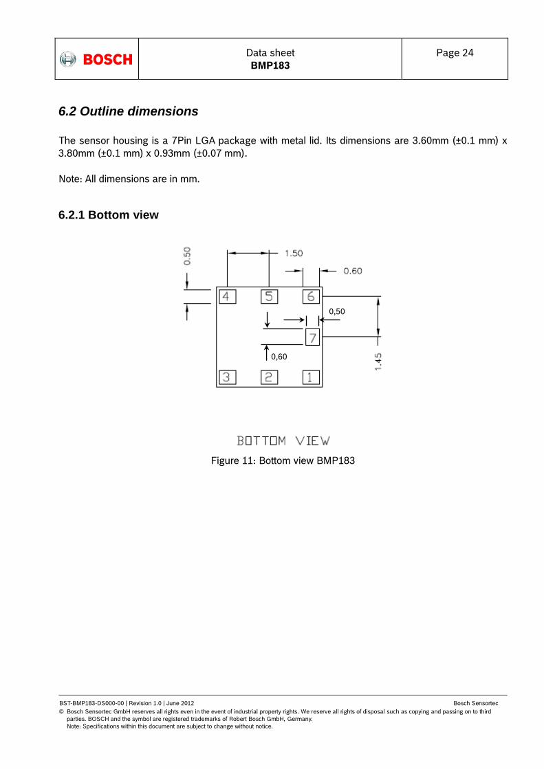
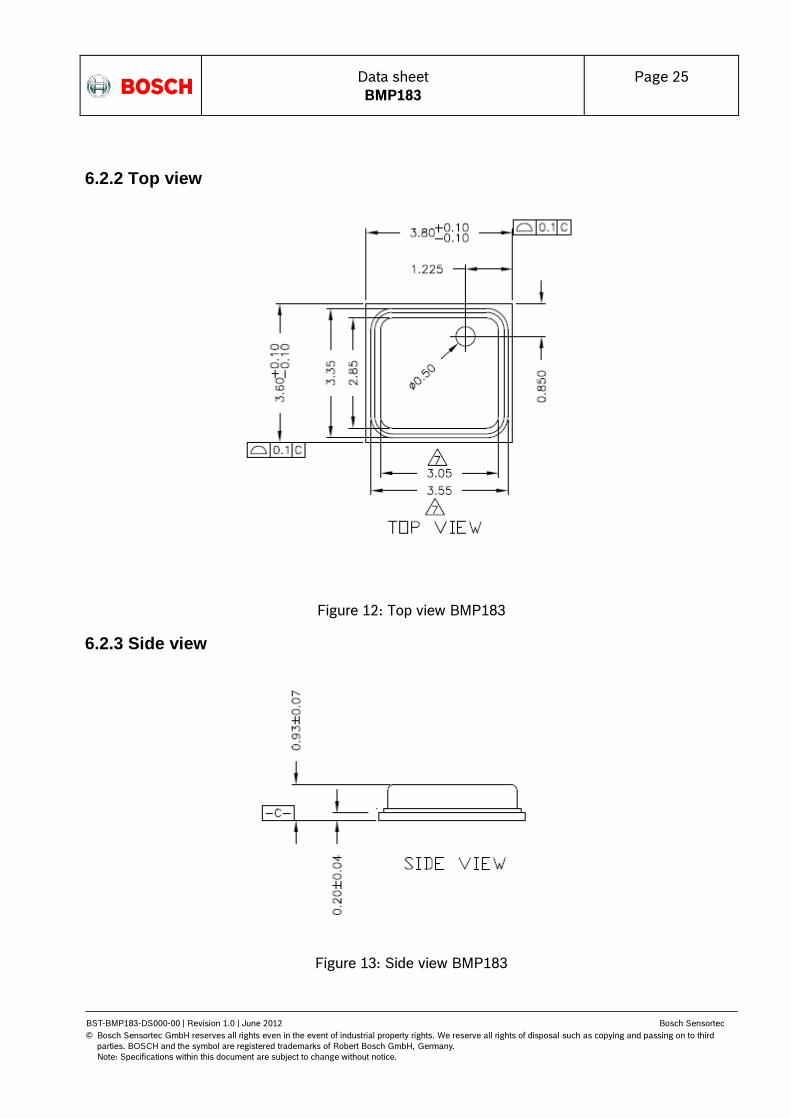
6.2 Outline dimensions
The sensor housing is a 7Pin LGA package with metal lid. Its dimensions are 3.60mm (±0.1 mm) x
3.80mm (±0.1 mm) x 0.93mm (±0.07 mm).
Note: All dimensions are in mm.
6.2.1 Bottom view
Figure 11: Bottom view BMP183
0,60
0,50
Data sheet
BMP183
Page 25
BST-BMP183-DS000-00 | Revision 1.0 | June 2012 Bosch Sensortec
© Bosch Sensortec GmbH reserves all rights even in the event of industrial property rights. We reserve all rights of disposal such as copying and passing on to third
parties. BOSCH and the symbol are registered trademarks of Robert Bosch GmbH, Germany.
Note: Specifications within this document are subject to change without notice.
6.2.2 Top view
Figure 12: Top view BMP183
6.2.3 Side view
Figure 13: Side view BMP183

Data sheet
BMP183
Page 26
BST-BMP183-DS000-00 | Revision 1.0 | June 2012 Bosch Sensortec
© Bosch Sensortec GmbH reserves all rights even in the event of industrial property rights. We reserve all rights of disposal such as copying and passing on to third
parties. BOSCH and the symbol are registered trademarks of Robert Bosch GmbH, Germany.
Note: Specifications within this document are subject to change without notice.
6.3 Moisture sensitivity level and soldering
The BMP183 is classified MSL 1 (moisture sensitivity level) according to IPC/JEDEC standards J-
STD-020D and J-STD-033A.
The device can be soldered Pb-free with a peak temperature of 260°C for 20 to 40 sec. The
minimum height of the solder after reflow shall be at least 50µm. This is required for good
mechanical decoupling between the sensor device and the printed circuit board (PCB).
To ensure good solder-ability, the devices shall be stored at room temperature (20°C).
The soldering process can lead to an offset shift.
6.4 RoHS compliancy
The BMP183 sensor meets the requirements of the EC directive "Restriction of hazardous
substances (RoHS)", please refer also to:
"Directive 2002/95/EC of the European Parliament and of the Council of 27 January 2003 on the
restriction of the use of certain hazardous substances in electrical and electronic equipment".
The BMP183 sensor is also halogen-free.
6.5 Mounting and assembly recommendations
In order to achieve the specified performance for you design, the following recommendations and the “Handling, soldering & mounting instructions BMP183” should be taken into consideration when mounting a pressure sensor on a printed-circuit board (PCB):
The clearance above the metal lid shall be 0.1mm at minimum.
For the device housing appropriate venting needs to be provided in case the ambient pressure shall be measured.
Liquids shall not come into direct contact with the device.
During operation the sensor is sensitive to light, which can influence the accuracy of the measurement (photo-current of silicon).
The BMP183 shall not the placed close the fast heating parts. In case of gradients > 3°C/sec. it is recommended to follow Bosch Sensortec application note ANP015, "Correction of errors induced by fast temperature changes". Please contact your Bosch Sensortec representative for details.

Data sheet
BMP183
Page 27
BST-BMP183-DS000-00 | Revision 1.0 | June 2012 Bosch Sensortec
© Bosch Sensortec GmbH reserves all rights even in the event of industrial property rights. We reserve all rights of disposal such as copying and passing on to third
parties. BOSCH and the symbol are registered trademarks of Robert Bosch GmbH, Germany.
Note: Specifications within this document are subject to change without notice.
7. Legal disclaimer
7.1 Engineering samples
Engineering Samples are marked with an asterisk (*) or (e). Samples may vary from the valid
technical specifications of the product series contained in this data sheet. They are therefore not
intended or fit for resale to third parties or for use in end products. Their sole purpose is internal
client testing. The testing of an engineering sample may in no way replace the testing of a product
series. Bosch Sensortec assumes no liability for the use of engineering samples. The Purchaser
shall indemnify Bosch Sensortec from all claims arising from the use of engineering samples.
7.2 Product use
Bosch Sensortec products are developed for the consumer goods industry. They may only be used
within the parameters of this product data sheet. They are not fit for use in life-sustaining or security
sensitive systems. Security sensitive systems are those for which a malfunction is expected to lead
to bodily harm or significant property damage. In addition, they are not fit for use in products which
interact with motor vehicle systems.
The resale and/or use of products are at the purchaser‟s own risk and his own responsibility. The
examination of fitness for the intended use is the sole responsibility of the Purchaser.
The purchaser shall indemnify Bosch Sensortec from all third party claims arising from any product
use not covered by the parameters of this product data sheet or not approved by Bosch Sensortec
and reimburse Bosch Sensortec for all costs in connection with such claims.
The purchaser must monitor the market for the purchased products, particularly with regard to
product safety, and inform Bosch Sensortec without delay of all security relevant incidents.
7.3 Application examples and hints
With respect to any examples or hints given herein, any typical values stated herein and/or any
information regarding the application of the device, Bosch Sensortec hereby disclaims any and all
warranties and liabilities of any kind, including without limitation warranties of non-infringement of
intellectual property rights or copyrights of any third party. The information given in this document
shall in no event be regarded as a guarantee of conditions or characteristics. They are provided for
illustrative purposes only and no evaluation regarding infringement of intellectual property rights or
copyrights or regarding functionality, performance or error has been made.

Data sheet
BMP183
Page 28
BST-BMP183-DS000-00 | Revision 1.0 | June 2012 Bosch Sensortec
© Bosch Sensortec GmbH reserves all rights even in the event of industrial property rights. We reserve all rights of disposal such as copying and passing on to third
parties. BOSCH and the symbol are registered trademarks of Robert Bosch GmbH, Germany.
Note: Specifications within this document are subject to change without notice.
8. Document history and modification
Rev. No Chapter Description of modifications/changes Date
1.0 All Document creation 13-06-2012
Bosch Sensortec GmbH
Gerhard-Kindler-Strasse 8
72770 Reutlingen / Germany
www.bosch-sensortec.com
Modifications reserved | Printed in Germany
Specifications are subject to change without notice
Revision_1.0_062012
Document number: BST-BMP183-DS000-00


