
RE 92510/10.2014, Bosch Rexroth AG
Characteristics Variable axial piston pump of swashplate design for
hydrostatic drives in open circuit. For use preferably in mobile applications Flow is proportional to the drive speed and displace-
ment. The fl ow can be infi nitely varied by adjusting the swash-
plate angle. The pump can work either self-priming or with a charge
pump. Special control devices program for mobile applications,
with diff erent control and regulation functions. The universal through drive is suitable for adding gear
pumps and axial piston pumps up to the same size, i.e. 100 % through drive.
Compact design High effi ciency High power density Low noise level
Sizes 110 to 280 Nominal pressure 350 bar (5100 psi) Maximum pressure 420 bar (6100 psi) Open circuit
Axial piston variable pumpA11V(L)O series 40
RE 92510Issue: 10.2014Replaces: 10.2013
ContentsOrdering code 2Hydraulic fl uids 5Shaft seal ring 6Charge pump (impeller) 6Operating pressure range 7Technical data 8Power control 12Stroke limiter 18Pressure control 22Dimensions size 110 25Dimensions size 145 30Dimensions size 175 37Dimensions size 210 44Dimensions size 280 51Through drives dimensions 57Overview of attachment options 60Combination pumps A11V(L)O + A11V(L)O 61Connector for solenoids 62Installation instructions 63Project planning notes 65Safety instructions 65

Bosch Rexroth AG, RE 92510/10.2014
2 A11V(L)O series 40 | Axial piston variable pumpOrdering code
Axial piston unit01 Variable swashplate design, nominal pressure 350 bar (5100 psi), maximum pressure 420 bar (6100 psi) A11V
Operation mode 110 145 175 210 28002 Pump,
open circuitwithout charge pump O
with charge pump ‒ LO
Size (NG)03 Geometric displacement cm3 110 145 175 210 280
in3 6.71 8.85 10.68 12.81 17.09
Control devices basic controller1) 110 145 175 210 28004 Power control fi xed setting LR
Override electric-proportional negative control U = 12 V L3
U = 24 V L4
hydraulic-proportional, negative control L5
positive control L6
Summation power controller
override hydraulic proportional, high pressure
negative control with stop CR
without stop PR
Stroke control2) electric-proportional positive control U = 12 V E1
U = 24 V E2
hydraulic-proportional,Control pressure
negative control Δp = 25 bar (365 psi)
H3
positive control H4
Pressure control with one-side swi-veling
fi xed setting DR
remote controlled hydraulically positive control DG
Additional control: Pressure control 110 145 175 210 28005 Without additional control (without symbol)
Pressure control with one-side swi-veling
fi xed setting DR
remote controlled hydraulically positive control DG
Additional control: stroke control or unloading 110 145 175 210 28006 Without additional control (without symbol)
Stroke control4) electric-proportional positive control U = 12 V E1
U = 24 V E2
hydraulic-proportional,Control pressure
negative control Δp = 25 bar (365 psi)
H3
positive control H4
Additional control: Load sensing 110 145 175 210 28007 Without additional control (without symbol)
Load sensing, internal pump pressure, fi xed setting S0
Depressurized basic position and external control pressure supply 110 145 175 210 28008 Maximum swivel angle (Vg max)
Without external control pressure supply (standard for power and pressure controllers) A
With external control pressure supply (integrated shuttle valve, standard for negative stroke control) B
Minimum swivel angle (Vg min)
With external control pressure supply (integrated shuttle valve, standard for positive stroke control) C
Ordering code
01 02 03 04 05 06 07 08 09 10 11 12 13 14 15 16 17 18 19 20 21
A11V / 40 1 0 –
1) The basic controller (04) can be combined with at most two additional controllers (05, 06, 07)
2) The stroke control systems can be combined with either pressure controllers or load sensing controllers. A combination of all three controllers is not possible.

RE 92510/10.2014, Bosch Rexroth AG
Axial piston variable pump | A11V(L)O series 40 Ordering code
3
Connectors for solenoids3) 110 145 175 210 28009 Without connector (without solenoid, only for hydraulic control) 0
DEUTSCH - molded connector, 2-pin, without suppressor diode P
Swivel angle sensor 110 145 175 210 28010 Without swivel angle sensor 0
With electric swivel angle sensor4)
(as per data sheet 95150)Power supply 5 V DC B
Power supply 8 V - 32 V DC K
Series11 Series 4, index 0 40
Confi guration of ports and fastening threads12 Metric, all fastening threads according to DIN 13, all port threads with O-ring seal according to ISO 6149 M
ANSI, all fastening threads according to ASME B1.1, all port threads with O-ring seal according to ISO 11926 A
Direction of rotation 110 145 175 210 28013 With view on drive shaft clockwise R
counter clockwise L
Sealing material 110 145 175 210 28014 FKM (fl uor-caoutchouc) V
Mounting fl anges 110 145 175 210 28015 SAE J744 152-4 ‒ ‒ ‒ D4
165-4 ‒ ‒ E4
SAE J617 409-12 ‒ G3
Drive shaft (permissible input torque, see page 11) 110 145 175 210 28016 Splined shaft ANSI B92.1a 1 3/4 in 13T 8/16 DP ‒ T1
2 in 15T 8/16 DP ‒ ‒ T2
2 1/4 in 17T 8/16 DP ‒ ‒ ‒ ‒ T3
Splined shaft DIN 5480 W45x2x21x9g ‒ ‒ ‒ ‒ A1
W50x2x24x9g ‒ ‒ A2
W60x2x28x9g ‒ ‒ ‒ ‒ A4
Working line port17 SAE fl ange port A, at side (45° right), SAE fl ange port S at bottom 1
Rotary group version 110 145 175 210 28018 Noise-optimized for n = 1500/1800 rpm, only for version without charge pump E
Version with charge pump ‒ S
= Available = On request ‒ = Not available
01 02 03 04 05 06 07 08 09 10 11 12 13 14 15 16 17 18 19 20 21
A11V / 40 1 0 –
3) Connectors for other electric components may deviate4) Please contact us if the swivel angle sensor is used for control
Bosch Rexroth AG, RE 92510/10.2014
4 A11V(L)O series 40 | Axial piston variable pumpOrdering code
01 02 03 04 05 06 07 08 09 10 11 12 13 14 15 16 17 18 19 20 21
A11V / 40 1 0 –
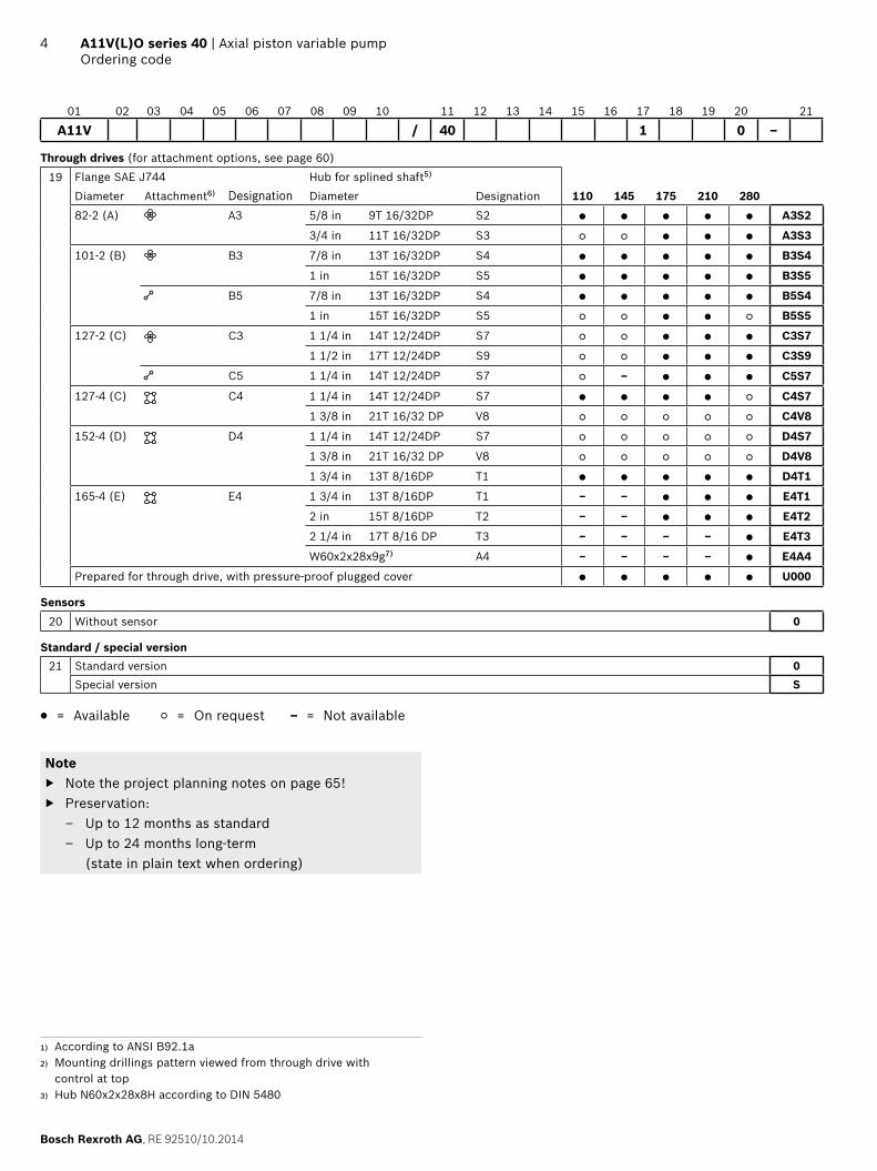
Through drives (for attachment options, see page 60)
19 Flange SAE J744 Hub for splined shaft5)
Diameter Attachment6) Designation Diameter Designation 110 145 175 210 28082-2 (A) A3 5/8 in 9T 16/32DP S2 A3S2
3/4 in 11T 16/32DP S3 A3S3
101-2 (B) B3 7/8 in 13T 16/32DP S4 B3S4
1 in 15T 16/32DP S5 B3S5
B5 7/8 in 13T 16/32DP S4 B5S4
1 in 15T 16/32DP S5 B5S5
127-2 (C) C3 1 1/4 in 14T 12/24DP S7 C3S7
1 1/2 in 17T 12/24DP S9 C3S9
C5 1 1/4 in 14T 12/24DP S7 – C5S7
127-4 (C) C4 1 1/4 in 14T 12/24DP S7 C4S7
1 3/8 in 21T 16/32 DP V8 C4V8
152-4 (D) D4 1 1/4 in 14T 12/24DP S7 D4S7
1 3/8 in 21T 16/32 DP V8 D4V8
1 3/4 in 13T 8/16DP T1 D4T1
165-4 (E) E4 1 3/4 in 13T 8/16DP T1 – – E4T1
2 in 15T 8/16DP T2 – – E4T2
2 1/4 in 17T 8/16 DP T3 – – – – E4T3
W60x2x28x9g7) A4 – – – – E4A4
Prepared for through drive, with pressure-proof plugged cover U000
Sensors20 Without sensor 0
Standard / special version21 Standard version 0
Special version S
= Available = On request – = Not available
Note Note the project planning notes on page 65! Preservation:
– Up to 12 months as standard – Up to 24 months long-term
(state in plain text when ordering)
1) According to ANSI B92.1a2) Mounting drillings pattern viewed from through drive with
control at top3) Hub N60x2x28x8H according to DIN 5480

RE 92510/10.2014, Bosch Rexroth AG
Axial piston variable pump | A11V(L)O series 40 Hydraulic fl uids
5
1) At temperatures below -25 °C (-13 °F) an NBR shaft seal is required (permissible temperature range -40 °C to +90 °C (-40 °F to +194 °F))
Hydraulic fl uids
The A11V(L)O variable pump is designed for operation with HLP mineral oil according to DIN 51524. Application instructions and requirements for hydraulic fl uids should be taken from the following data sheets before the start of project planning:
90220: Hydraulic fl uids based on mineral oils and rela-ted hydrocarbons
90221: Environmentally acceptable hydraulic fl uids 90222: Fire-resistant, water-free hydraulic fl uids
(HFDR/HFDU)
Notes on selection of hydraulic fl uidThe hydraulic fl uid should be selected such that the opera-ting viscosity in the operating temperature range is within the optimum range (νopt: see selection diagram).NoteAt no point of the component may the temperature be higher than 115 °C (240 °F). The temperature diff erence specifi ed in the table is to be taken into account when determining the viscosity in the bearing.If the above conditions cannot be maintained due to ext-reme operating parameters, please contact the responsible member of staff at Bosch Rexroth.
Viscosity and temperature of hydraulic fl uids
Viscosity Temperature Comment
Cold start νmax ≤ 1600 mm2/s(νmax ≤ 7400 SUS)
θSt ≥ -25 °C (-13 °F)1) t ≤ 3 min, without load (20 bar (290 psi) ≤ p ≤ 50 bar (725 psi)), n ≤ 1000 rpm
Permissible temperature diff erence ΔT ≤ 25 K (45 °F) between axial piston unit and hydraulic fl uid
Warm-up phase ν < 1600 to 400 mm2/s(ν < 7400 to 1850 SUS)
θ = -40 °C to -25 °C(θ = -40 °F to -13 °F)
at p ≤ 0.7 × pnom, n ≤ 0.5 × nnom and t ≤ 15 min
Operating pha-se
ν = 400 to 10 mm2/s(ν = 1850 to 60 SUS)
This corresponds, for example on the VG 46, to a temperature range of +5 °C (41 °F) to +85 °C (185 °F) (see selection diagram)
θ = -25 °C to +110 °C(θ = -13 °F to +230 °F)
measured at port TNote the permissible temperature range of the shaft seal(ΔT = approx. 5 K (9 °F) between the bearing/shaft seal and port T)
νopt = 36 to 16 mm2/s(νopt = 170 to 74 SUS)
Range of optimum operating viscosity and effi ciency
Short-term operation
νmin 7 mm2/s (50 SUS) t < 3 min, p < 0.3 × pnom
Selection diagram
-40 -25 -10 10 30 50 90 115700-40 -13 -14 50 86 122 194 24015832
50
60
200300
100
500
1000
2000300046007400
VG 22VG 32VG 46VG 68
VG 100
74
170
7
10
4060
20
100
200
400600
10001600
[SUS][mm2/s]
[°C][°F]
16
36
Range of optimum operating viscosity vopt
Optimum effi ciency
Maximum permissible viscosity for cold start
Minimum permissible viscosity for short-term operation
Temperature θ
Visc
osity
v
Con
tinuo
us o
pera
tion
Warm-up phase
Minimum permissible temperature for cold start

Bosch Rexroth AG, RE 92510/10.2014
6 A11V(L)O series 40 | Axial piston variable pumpShaft seal ring
Filtration of the hydraulic fl uidFiner fi ltration improves the cleanliness level of the hydraulic fl uid, which increases the service life of the axial piston unit. A cleanliness level of at least 20/18/15 is to be maintained according to ISO 4406.At very high hydraulic fl uid temperatures (90 °C (195 °F to maximum 115 °C (240 °F)), a cleanliness class of at least 19/17/14 according to ISO 4406 is necessary. Please contact us if the above classes cannot be observed.
Shaft seal ring
The FKM shaft seal ring may be used for leak temperatures from -25 °C (-13 °F) to +115 °C (240 °F).
NoteFor applications below -25 °C (-13 °F) an NBR shaft seal is required (permissible temperature range -40 °C (-40 °F) to +90 °C (+195 °F); ordering code digit 14, K). Please contact us.
Charge pump (impeller)
The charge pump is a circulating pump with which the A11VLO is fi lled and therefore can be operated at higher speeds. This also simplifi es cold starting at low temperatu-res and high viscosity of the hydraulic fl uid. Externally increasing the inlet pressure is therefore unnecessary in most cases. Charging the reservoir with compressed air is not permissible.
MA A P
V g m
in
V g m
ax
S M T2 T3T1

RE 92510/10.2014, Bosch Rexroth AG
Axial piston variable pump | A11V(L)O series 40 Operating pressure range
7
Operating pressure range
Pressure at working line port A Defi nition
Nominal pressure pnom 350 bar (5100 psi) absolute The nominal pressure corresponds to the maximum design pressure.
Maximum pressure pmax 420 bar (6100 psi) absolute The maximum pressure corresponds the maximum operating pressure within the single operating period. The sum of the single operating periods must not exceed the total operating period.
Single operating period 10 s
Total operating period 300 h
Minimum pressure pA abs
(High-pressure side)Minimum pressure on the high-pressure side (A) which is required in order to prevent damage to the axial piston unit. The minimum pressure depends on the rotational speed and the swivel angle (see diagram).
Rate of pressure change RA max 16000 bar/s (232000 psi/s) Maximum permissible rate of pressure build-up and pressure reduction during a pressure change over the entire pressure range.
Pressure at suction port S (Inlet)
Version without charge pump Minimum pressure at suction port S (inlet) that is required in order to avoid damage to the axial piston unit. The minimum pressure depends on the speed and displacement of the axial piston unit.
Minimum pressure pS min ≥ 0.8 bar (12 psi) absolute
Maximum pressure pS max ≤ 30 bar (435 psi) absolute
Version with charge pump
Minimum pressure pS min ≥ 0.7 bar (10.5 psi) absolute
Maximum pressure pS max ≤ 2 bar (30 psi) absolute
Drain pressure at the port T1, T2, T3
Maximum pressure pL max 4 bar (60 psi) absolute Maximum 1.2 bar (18 psi) higher than inlet pressure at port S, but not higher than pL max.
A case drain line to the reservoir is required.
Rate of pressure change RA max
pnom
Δt
Δp
Time t
Pres
sure
p
Pressure defi nition
Pres
sure
p
t1
t2tn
Minimum pressure (high pressure side)
Maximum pressure pmax
Nominal pressure pnom
Time tTotal operating period = t1 + t2 + ... + tn
Minimum pressure (high pressure side)
0.50 1.0
290
260
230
200
175
145
115
90
20
18
16
14
12
10
8
6
[bar] [psi]
A11VLO at n ≦ nmax
A11VO at n > nnom
A11VO at n ≦ nnom
p A a
bs
Displacement Vg / Vg max
NoteOperating pressure range valid when using hydraulic fl uids based on mineral oils. Values for other hydraulic fl uids, please contact us.
Single operating period

Bosch Rexroth AG, RE 92510/10.2014
8 A11V(L)O series 40 | Axial piston variable pumpTechnical data
Technical data
Without charge pump (A11VO)
Size NG 110 145 175 210 280
Displacement, geometric, per revolution Vg max cm3 110.0 145.0 175.0 210.0 280.0
in3 6.71 8.85 10.68 12.81 17.09
Vg min cm3 0 0 0 0 0
in3 0 0 0 0 0
Maximum rotational speed1)
at Vg max2) nnom min-1 2400 2300 2150 2100 1800
at Vg ≤ Vg max3) nmax min-1 2800 2600 2500 2500 2300
Flow At nnom and Vg max qv l/min 264 334 376 441 504
gpm 70 88 99 117 133
Power at nnom, Vg max and Δp = 350 bar (5100 psi) P kW 154 195 219 257 294
hp 207 261 294 345 394
Torque at Vg max and Δp = 350 bar (5100 psi)2) T Nm 613 808 975 1170 1560
lb-ft 452 596 719 863 1151
Rotary stiff nessdrive shaft
1 3/4 in 13T 8/16 DP T1 c kNm/rad ‒ 235 243 254 ‒
lb-ft/rad ‒ 173327 179227 187340 ‒
2 in 15T 8/16 DP T2 c kNm/rad ‒ 286 298 314 ‒
lb-ft/rad ‒ 210942 219794 231595 ‒
2 1/4 in 17T 8/16 DP T3 c kNm/rad ‒ ‒ ‒ ‒ 519
lb-ft/rad ‒ ‒ ‒ ‒ 382795
W45x2x21x9g A1 c kNm/rad 242 ‒ ‒ ‒ ‒
lb-ft/rad 178489 ‒ ‒ ‒ ‒
W50x2x24x9g A2 c kNm/rad ‒ 334 357 381 ‒
lb-ft/rad ‒ 246345 263309 281011 ‒
W60x2x28x9g A4 c kNm/rad ‒ ‒ ‒ ‒ 645
lb-ft/rad ‒ ‒ ‒ ‒ 475727
Moment of inertia rotary group JGR kgm2 0.022 0.035 0.045 0.06 0.097
lb-ft2 0.5221 0.8306 1.0679 1.4238 2.3019
Maximum angular acceleration4) α wheel/s² 7465 6298 5609 5014 4200
Case volume V L 2.2 2.7 3.6 4 6.5
gal 0.58 0.71 0.95 1.06 1.72
Weight (without through drive) approx. m kg 64 79 97 111 143
lbs 141 174 214 245 315
1) The values are applicable: – for the optimum viscosity range from νopt = 36 to 16 mm2/s
(170 to 74 SUS) – with hydraulic fl uid on the basis of mineral oil
2) The values apply at absolute pressure pabs = 1 bar (15 psi) at suction port S.
3) Maximum rotational speed (rotational speed limit) in the case of increasing the inlet pressure pabs at suction port S and Vg < Vg max, see diagram on page 10.
4) The data are valid for values between the minimum required and maximum permissible speed. Valid for external excitation (e. g. die-sel engine 2 to 8 times rotary frequency; cardan shaft twice the rotary frequency). The limiting value is only valid for a single pump. The load capacity of the connection parts must be considered.

RE 92510/10.2014, Bosch Rexroth AG
Axial piston variable pump | A11V(L)O series 40 Technical data
9
With charge pump (A11VLO)
Size NG 145 175 210 280
Displacement, geometric, per revolution Vg max cm3 145.0 175.0 210.0 280.0
in3 8.85 10.68 12.81 17.09
Vg min cm3 0 0 0 0
in3 0 0 0 0
Maximum rotational speed1)
at Vg max2) nnom min-1 2600 2500 2500 2300
at Vg ≤ Vg max3) nmax min-1 2600 2500 2500 2300
Flow At nnom and Vg max qv l/min 377 438 525 644
gpm 100 116 139 170
Power at nnom, Vg max and Δp = 350 bar (5100 psi) P kW 220 255 306 376
hp 295 342 410 504
Torque at Vg max and Δp = 350 bar (5100 psi)2) T Nm 808 975 1170 1560
lb-ft 596 719 863 1151
Rotary stiff nessdrive shaft
1 3/4 in 13T 8/16 DP T1 c kNm/rad 235 243 254 ‒
lb-ft/rad 173327 179227 187340 ‒
2 in 15T 8/16 DP T2 c kNm/rad 286 298 314 ‒
lb-ft/rad 210942 219794 231595 ‒
2 1/4 in 17T 8/16 DP T3 c kNm/rad ‒ ‒ ‒ 519
lb-ft/rad ‒ ‒ ‒ 382795
W50x2x24x9g A2 c kNm/rad 334 357 381 ‒
lb-ft/rad 246345 263309 281011 ‒
W60x2x28x9g A4 c kNm/rad ‒ ‒ ‒ 645
lb-ft/rad ‒ ‒ ‒ 475727
Moment of inertia rotary group JGR kgm2 0.035 0.047 0.063 0.097
lb-ft2 0.8306 1.0679 1.4238 2.3019
Maximum angular acceleration4) α wheel/s² 6298 5609 5014 4200
Case volume V L 2.9 3.6 3.7 5.6
gpm 0.77 0.95 0.98 1.48
Weight (without through drive) approx. m kg 92 110 125 148
lbs 203 243 276 326
1) The values are applicable: – for the optimum viscosity range from νopt = 36 to 16 mm2/s
(170 to 74 SUS) – with hydraulic fl uid on the basis of mineral oil
2) The values apply at absolute pressure pabs = 1 bar (15 psi) at suction port S.
3) Maximum rotational speed (rotational speed limit) in the case of increasing the inlet pressure pabs at suction port S and Vg < Vg max, see diagram on page 10.
4) The data are valid for values between the minimum required and maximum permissible speed. Valid for external excitation (e. g. die-sel engine 2 to 8 times rotary frequency; cardan shaft twice the rotary frequency). The limiting value is only valid for a single pump. The load capacity of the connection parts must be considered.
Bosch Rexroth AG, RE 92510/10.2014
10 A11V(L)O series 40 | Axial piston variable pumpTechnical data
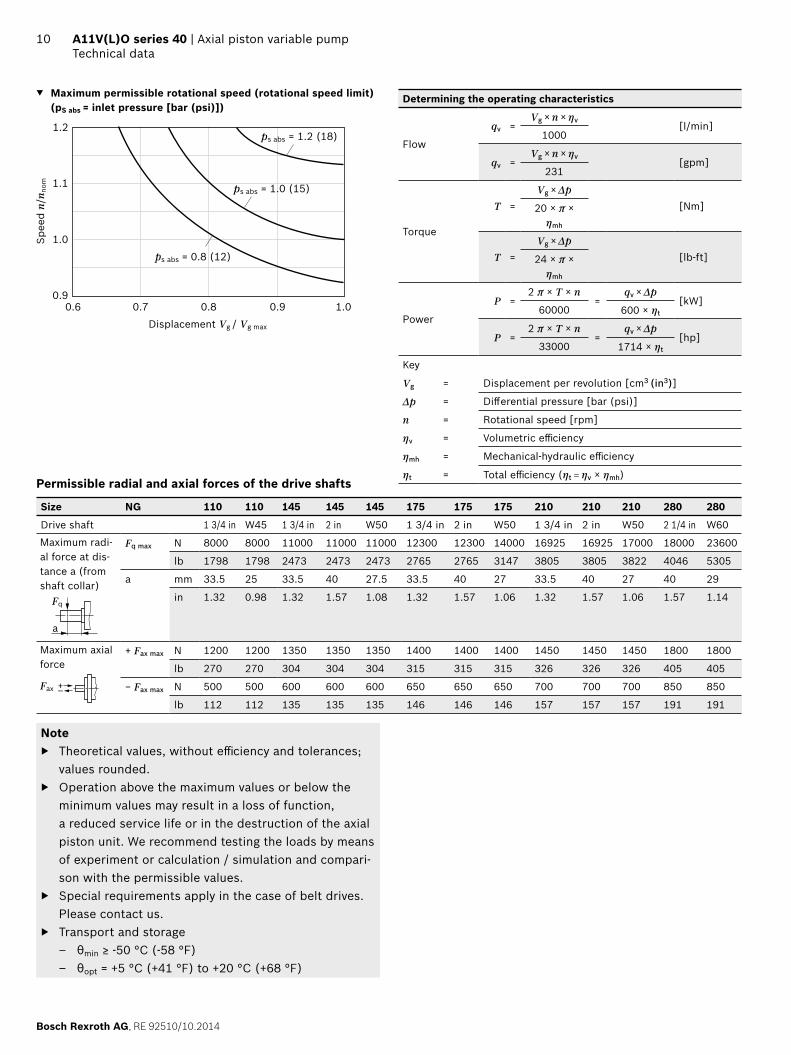
Maximum permissible rotational speed (rotational speed limit)(pS abs = inlet pressure [bar (psi)])
1.2
0.6 0.7 0.8 0.9 1.00.9
1.0
1.1
ps abs = 1.2 (18)
ps abs = 1.0 (15)
ps abs = 0.8 (12)
Spee
d n/
n nom
Displacement Vg / Vg max
Permissible radial and axial forces of the drive shafts
Size NG 110 110 145 145 145 175 175 175 210 210 210 280 280
Drive shaft 1 3/4 in W45 1 3/4 in 2 in W50 1 3/4 in 2 in W50 1 3/4 in 2 in W50 2 1/4 in W60
Maximum radi-al force at dis-tance a (from shaft collar)
a
Fq
Fq max N 8000 8000 11000 11000 11000 12300 12300 14000 16925 16925 17000 18000 23600
lb 1798 1798 2473 2473 2473 2765 2765 3147 3805 3805 3822 4046 5305
a mm 33.5 25 33.5 40 27.5 33.5 40 27 33.5 40 27 40 29
in 1.32 0.98 1.32 1.57 1.08 1.32 1.57 1.06 1.32 1.57 1.06 1.57 1.14
Maximum axial force
–+Fax
+ Fax max N 1200 1200 1350 1350 1350 1400 1400 1400 1450 1450 1450 1800 1800
lb 270 270 304 304 304 315 315 315 326 326 326 405 405
− Fax max N 500 500 600 600 600 650 650 650 700 700 700 850 850
lb 112 112 135 135 135 146 146 146 157 157 157 191 191
Note Theoretical values, without effi ciency and tolerances;
values rounded. Operation above the maximum values or below the
minimum values may result in a loss of function, a reduced service life or in the destruction of the axial piston unit. We recommend testing the loads by means of experiment or calculation / simulation and compari-son with the permissible values.
Special requirements apply in the case of belt drives. Please contact us.
Transport and storage – θmin ≥ -50 °C (-58 °F) – θopt = +5 °C (+41 °F) to +20 °C (+68 °F)
Determining the operating characteristics
Flow
qv =Vg × n × ηv
[l/min]1000
qv =Vg × n × ηv
[gpm]231
Torque
T = Vg × Δp
[Nm]20 × π × ηmh
T = Vg × Δp
[lb-ft]24 × π × ηmh
Power
P =2 π × T × n
=qv × Δp
[kW]60000 600 × ηt
P =2 π × T × n
=qv × Δp
[hp]33000 1714 × ηt
Key
Vg = Displacement per revolution [cm3 (in3)]
Δp = Diff erential pressure [bar (psi)]
n = Rotational speed [rpm]
ηv = Volumetric effi ciency
ηmh = Mechanical-hydraulic effi ciency
ηt = Total effi ciency (ηt = ηv × ηmh)

RE 92510/10.2014, Bosch Rexroth AG
Axial piston variable pump | A11V(L)O series 40 Technical data
11A11V(L)O series 40 | Axial piston variable pumpTechnical data
Permissible input and through-drive torques
Size NG 110 145 175 210 280
Torque at Vg max and Δp = 350 bar (5100 psi)1) Tmax Nm 610 808 975 1170 1560
lb-ft 452 596 719 863 1151
Input torque at drive shaft, maximum2)
T1 1 3/4 in TE max Nm 1640 1640 1640 1640 –
lb-ft 1210 1210 1210 1210 –
T2 2 in TE max Nm – 2670 2670 2670 –
lb-ft – 1969 1969 1969 –
T3 2 1/4 in TE max Nm – – – – 4380
lb-ft – – – – 3231
A1 W45 TE max Nm 2190 – – – –
lb-ft – – – –
A2 W50 TE max Nm – 3140 3140 3140 –
lb-ft – 2316 2316 2316 –
A4 W60 TE max Nm – – – – 5780
lb-ft – – – – 4263
Maximum through-drive torque TD max Nm 960 1110 1340 1915 2225
lb-ft 708 819 988 1412 1641
Distribution of torques
TE
TD
T1 T2
T31st pump
Torque at 1st pump T1
Torque at 2nd pump T2
Torque at 3rd pump T3
Input torque TE = T1 + T2 + T3
TE < TE max
Through-drive torque TD = T2 + T3
TD < TD max
External control pressure supply (ordering code digit 08 B and C)Control systems with external control pressure supply need a fl ow appropriate to the adjustment time and size.
Size Maximum fl ow [l/min (gpm)]
110 10 (2.64)
145 13 (3.43)
175 14 (3.70)
210 17 (4.49)
280 22 (5.81)
2nd pump
1) Effi ciency not considered2) For drive shafts free of radial force

Bosch Rexroth AG, RE 92510/10.2014
12 A11V(L)O series 40 | Axial piston variable pumpPower control
Power control
LR – Power controller, fi xed settingThe power control regulates the displacement of the pump depending on the operating pressure so that a given drive power is not exceeded at constant drive speed.The precise control with a hyperbolic control characteristic, provides an optimum utilization of available power.The operating pressure acts on a rocker via a measuring piston moved together with the control. An externally adjus-table spring force counteracts this, it determines the power setting. The depressurized basic position is Vg max.If the operating pressure exceeds the set spring force, the control valve will be actuated by the rocker and the pump will swivel back from the basic position Vg max toward Vg min. Here, the leverage at the rocker may be shortened and the operating pressure may rise in the same relation as the displacement is reduced (pB × Vg = constant; pB = operating pressure; Vg = displacement).The hydraulic output power (characteristic LR) is infl u-enced by the effi ciency of the pump.Setting range for beginning of control 50 bar (725 psi) to 350 bar (5100 psi).When ordering, state in plain text:
Drive power P [kW] Drive speed n [rpm-1] Maximum fl ow qV max [l/min]
Please contact us if you need a power diagram.
Characteristic: LR
Ope
ratin
g pr
essu
re p
B [
bar]
Vg min displacement Vg max
350 bar(5100 psi)
50 bar(725 psi)
Schematic LR
MA A P
S M T2 T3T1
V g m
in
V g m
ax

RE 92510/10.2014, Bosch Rexroth AG
Axial piston variable pump | A11V(L)O series 40 Power control
13
L3/L4 – Power controller, electric-proportional override (negative control)A control current acts against the adjustment spring of the power control via a proportional solenoid.The mechanically adjusted basic power setting can be reduced by means of diff erent control current settings.Increasing control current = reduced power.If the pilot control signal is variably controlled via a load limiting control, the power draw of all consumers is adjus-ted to the power draw possible for the diesel engine (e.g. electronic load limiting control LLC (data sheet 95310) in BODAS controller RC2-2).
Technical data, solenoid L3 L4
Voltage 12 V (±20 %) 24 V (±20 %)
Control current
Beginning of control 400 mA 200 mA
End of control 1200 mA 600 mA
Limiting current 1.54 A 0.77 A
Nominal resistance (at 20 °C (68 °F)) 5.5 Ω 22.7 Ω
Dither frequency 100 Hz 100 Hz
Duty cycle 100 % 100 %
Type of protection: see connector version page 62
When ordering, state in plain text: Drive power P [kW (hp)] at beginning of control Control current I [mA] at drive power P [kW (hp)] Drive speed n [min-1 (rpm)] Maximum fl ow qV max [l/min (gpm)]
Eff ect of power override through current increase or de-energized operating condition
Ope
ratin
g pr
essu
re p
B [
bar]
Vg min displacement Vg max
NoteIn operating condition L3 de-energized (jump 400 to 0 mA): Power increase by a factor of 2 of the table values.In operating condition L4 de-energized (jump 200 to 0 mA): Power increase by a factor of 1 of the table values.
Schematic L3/L4
MA A P
S M T2 T3T1
V g m
in
V g m
ax
Reduction of power by control currentto the proportional solenoids with L31)
Power reduction/control current [kW (hp)/100 mA]
Speed [rpm]
Size 1000 1500 1800
110 6.1 (8.2) 9.2 (12.3) 11.0 (14.7)
145 7.4 (9.9) 11.1 (14.9) 13.3 (17.8)
175 8.4 (11.3) 12.6 (16.9) 15.1 (20.2)
210 9.4 (12.6) 14.1 (18.9) 16.9 (22.7)
280 11.4 (15.3) 17.1 (22.9) 20.5 (27.5)
Reduction of power by control currentto the proportional solenoids with L41)
Power reduction/control current [kW (hp)/100 mA]
Speed [rpm]
Size 1000 1500 1800
110 12.3 (16.5) 18.5 (24.8) 22.1 (29.6)
145 14.8 (19.8) 22.2 (29.8) 26.6 (35.7)
175 16.8 (22.5) 25.2 (33.8) 30.2 (40.5)
210 18.9 (25.3) 28.4 (38.1) 34.0 (45.6)
280 22.9 (30.7) 34.4 (46.1) 41.2 (55.3)
1) Values in the tables are reference points. Determination of the exact power override on request.
De-energized operating condition
Bosch Rexroth AG, RE 92510/10.2014
14 A11V(L)O series 40 | Axial piston variable pumpPower control
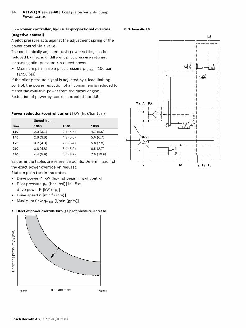
L5 – Power controller, hydraulic-proportional override (negative control)A pilot pressure acts against the adjustment spring of the power control via a valve.The mechanically adjusted basic power setting can be reduced by means of diff erent pilot pressure settings.Increasing pilot pressure = reduced power.
Maximum permissible pilot pressure pSt max = 100 bar (1450 psi)
If the pilot pressure signal is adjusted by a load limiting control, the power reduction of all consumers is reduced to match the available power from the diesel engine.Reduction of power by control current at port L5
Power reduction/control current [kW (hp)/bar (psi)]
Speed [rpm]
Size 1000 1500 1800
110 2.3 (3.1) 3.5 (4.7) 4.1 (5.5)
145 2.8 (3.8) 4.2 (5.6) 5.0 (6.7)
175 3.2 (4.3) 4.8 (6.4) 5.8 (7.8)
210 3.6 (4.8) 5.4 (5.9) 6.5 (8.7)
280 4.4 (5.9) 6.6 (8.9) 7.9 (10.6)
Values in the tables are reference points. Determination of the exact power override on request.State in plain text in the order:
Drive power P [kW (hp)] at beginning of control Pilot pressure pst [bar (psi)] in L5 at
drive power P [kW (hp)] Drive speed n [min-1 (rpm)] Maximum fl ow qV max [l/min (gpm)]
Eff ect of power override through pilot pressure increase
Ope
ratin
g pr
essu
re p
B [
bar]
Vg min displacement Vg max
Schematic L5
MA A PA
MS T2 T3T1
V g m
in
V g m
ax
L5

RE 92510/10.2014, Bosch Rexroth AG
Axial piston variable pump | A11V(L)O series 40 Power control
15
L6 – Power controller, hydraulic-proportional override (positive control)A pilot pressure acts together with the adjustment spring of the power control via a valve.The mechanically adjusted basic power setting can be increased by means of diff erent pilot pressure settings.Increasing pilot pressure = increased power.
Maximum permissible pilot pressure pSt max = 100 bar (1450 psi)
If the pilot pressure signal is adjusted by a load limiting control, the power increase of all consumers is increased to match the available power from the diesel engine.Power increase by pilot pressure at port L6
Power increase/pilot pressure [kW (hp)/bar (psi)]
Speed [rpm]
Size 1000 1500 1800
110 2.4 (3.2) 3.6 (4.8) 4.3 (5.8)
145 2.9 (3.9) 4.3 (5.8) 5.2 (7.0)
175 3.3 (4.4) 4.9 (6.6) 5.9 (7.9)
210 3.7 (5.0) 5.6 (7.5) 6.7 (9.0)
280 4.5 (6.0) 6.8 (9.1) 8.1 (10.9)
Values in the tables are reference points. Determination of the exact power override on request.State in plain text in the order:
Drive power P [kW (hp)] at beginning of control Pilot pressure pst [bar (psi)] in L6 at
drive power P [kW (hp)] Drive speed n [min-1 (rpm)] Maximum fl ow qV max [l/min (gpm)]
Eff ect of power override through pilot pressure increase
Ope
ratin
g pr
essu
re p
B [
bar]
Vg min displacement Vg max
Schematic L6
MA A PA
MS T2 T3T1
V g m
in
V g m
ax
L6
Bosch Rexroth AG, RE 92510/10.2014
16 A11V(L)O series 40 | Axial piston variable pumpPower control
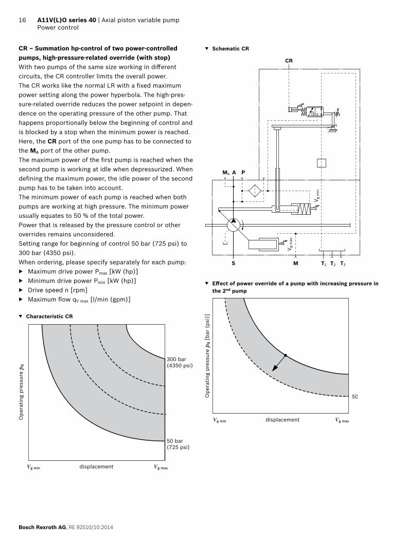
CR – Summation hp-control of two power-controlled pumps, high-pressure-related override (with stop)With two pumps of the same size working in diff erent circuits, the CR controller limits the overall power. The CR works like the normal LR with a fi xed maximum power setting along the power hyperbola. The high-pres-sure-related override reduces the power setpoint in depen-dence on the operating pressure of the other pump. That happens proportionally below the beginning of control and is blocked by a stop when the minimum power is reached. Here, the CR port of the one pump has to be connected to the MA port of the other pump.The maximum power of the fi rst pump is reached when the second pump is working at idle when depressurized. When defi ning the maximum power, the idle power of the second pump has to be taken into account.The minimum power of each pump is reached when both pumps are working at high pressure. The minimum power usually equates to 50 % of the total power.Power that is released by the pressure control or other overrides remains unconsidered.Setting range for beginning of control 50 bar (725 psi) to 300 bar (4350 psi).When ordering, please specify separately for each pump:
Maximum drive power Pmax [kW (hp)] Minimum drive power Pmin [kW (hp)] Drive speed n [rpm] Maximum fl ow qV max [l/min (gpm)]
Characteristic CR
Vg min displacement Vg max
Ope
ratin
g pr
essu
re p
B
300 bar(4350 psi)
50 bar(725 psi)
Schematic CR
CR
MA A P
S M T2 T3T1
V g m
in
V g m
ax Eff ect of power override of a pump with increasing pressure in
the 2nd pump
Vg min displacement Vg max
Ope
ratin
g pr
essu
re p
B [
bar
(psi
)]
50

RE 92510/10.2014, Bosch Rexroth AG
Axial piston variable pump | A11V(L)O series 40 Power control
17
PR – Summation hp-control of two power-controlled pump and a constant pumpTogether with the mounted fi xed pump, the PR controller on an A11V(L)O eff ects a limitation of the overall power. The PR works like the normal LR with a fi xed maximum power setting along the power hyperbola. The high-pres-sure-dependent override reduces the power specifi cation in proportion to the operating pressure of the fi xed pump. Here, port PR of the A11V(L)O must be connected to the operating pressure of the fi xed pump. The power of the controlled pump can then be reduced to zero in a border-line case.The maximum power of the controlled pump is reached when the fi xed pump works at idle when depressurized. When defi ning the maximum power, the idle power of the fi xed pump has to be taken into account.Power that is released by the pressure control or other overrides remains unconsidered.Setting range for beginning of control 50 bar (725 psi) to 350 bar (5100 psi).State in plain text in the order:
Maximum drive power Pmax [kW (hp)] Drive speed n [rpm] Maximum fl ow qV max [l/min (gpm)] Size of the fi xed pump
Characteristic PR
Vg min displacement Vg max
Ope
ratin
g pr
essu
re p
B [
bar]
350 bar(5100 psi)
50 bar(725 psi)
Schematic PR
PR
MA A P
S M T2 T3T1
V g m
in
V g m
ax
Eff ect of power override of a pump with increasing pressure in the 2nd pump
Vg min displacement Vg max
Ope
ratin
g pr
essu
re p
B
50 bar(725 psi)
Bosch Rexroth AG, RE 92510/10.2014
18 A11V(L)O series 40 | Axial piston variable pumpStroke limiter
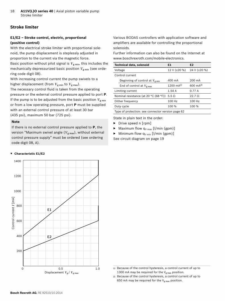
Stroke limiter
E1/E2 – Stroke control, electric, proportional (positive control)With the electrical stroke limiter with proportional sole-noid, the pump displacement is steplessly adjusted in proportion to the current via the magnetic force.Basic position without pilot signal is Vg min, this includes the mechanically depressurized basic position Vg min (see orde-ring code digit 08).With increasing control current the pump swivels to a higher displacement (from Vg min to Vg max).The necessary control fl uid is taken from the operating pressure or the external control pressure applied to port P.If the pump is to be adjusted from the basic position Vg min or from a low operating pressure, port P must be supplied with an external control pressure of at least 30 bar (435 psi), maximum 50 bar (725 psi).
NoteIf there is no external control pressure applied to P, the version “Maximum swivel angle (Vg max), without external control pressure supply” must be ordered (see ordering code digit 08, A).
Characteristic E1/E2
0 1.00.5
200
400
600
800
1000
1200
1400
Con
trol
cur
rent
I [
mA]
Displacement Vg / Vg max
E1
E2
Various BODAS controllers with application software and amplifi ers are available for controlling the proportional solenoids.Further information can also be found on the Internet at www.boschrexroth.com/mobile-electronics.
Technical data, solenoid E1 E2
Voltage 12 V (±20 %) 24 V (±20 %)
Control current
Beginning of control at Vg min 400 mA 200 mA
End of control at Vg max 1200 mA1) 600 mA2)
Limiting current 1.54 A 0.77 A
Nominal resistance (at 20 °C (68 °F)) 5.5 Ω 22.7 Ω
Dither frequency 100 Hz 100 Hz
Duty cycle 100 % 100 %
Type of protection: see connector version page 62
State in plain text in the order: Drive speed n [rpm] Maximum fl ow qV max [l/min (gpm)] Minimum flow qV min [l/min (gpm)]
See circuit diagram on page 19
1) Because of the control hysteresis, a control current of up to 1300 mA may be required for the Vg max position.
2) Because of the control hysteresis, a control current of up to 650 mA may be required for the Vg max position.

RE 92510/10.2014, Bosch Rexroth AG
Axial piston variable pump | A11V(L)O series 40 Stroke limiter
19
Schematic E1/E2
Shuttle valve only included with ordering code digit 08 B and C
MA A P
S M T2 T3T1
V g m
in
V g m
ax
Bosch Rexroth AG, RE 92510/10.2014
20 A11V(L)O series 40 | Axial piston variable pumpStroke limiter
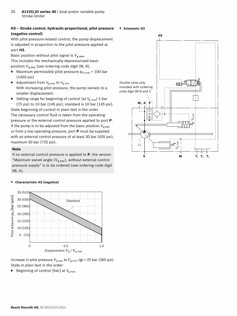
H3 – Stroke control, hydraulic-proportional, pilot pressure (negative control)With pilot-pressure-related control, the pump displacement is adjusted in proportion to the pilot pressure applied at port H3.Basic position without pilot signal is Vg max. This includes the mechanically depressurized basic position Vg max (see ordering code digit 08, B).
Maximum permissible pilot pressure pSt max = 100 bar (1450 psi)
Adjustment from Vg max to Vg min
With increasing pilot pressure, the pump swivels to a smaller displacement.
Setting range for beginning of control (at Vg max) 5 bar (75 psi) to 10 bar (145 psi), standard is 10 bar (145 psi).
State beginning of control in plain text in the order.The necessary control fl uid is taken from the operating pressure or the external control pressure applied to port P.If the pump is to be adjusted from the basic position Vg min or from a low operating pressure, port P must be supplied with an external control pressure of at least 30 bar (435 psi), maximum 50 bar (725 psi).
NoteIf no external control pressure is applied to P, the version “Maximum swivel angle (Vg max), without external control pressure supply” is to be ordered (see ordering code digit 08, A).
Characteristic H3 (negative)
Pilo
t pr
essu
re p
St [
bar
(psi
)]
Displacement Vg / Vg max
(75)
0 1.00.5
(510)
(435)
(145)
(220)
(290)
(365)
5
35
30
10
15
20
25
Standard
Increase in pilot pressure Vg max to Vg min: Δp = 25 bar (365 psi)State in plain text in the order:
Beginning of control [bar] at Vg max
Schematic H3
H3
MA A P
S M T2 T3T1
V g m
in
V g m
ax
Shuttle valve only included with ordering code digit 08 B and C

RE 92510/10.2014, Bosch Rexroth AG
Axial piston variable pump | A11V(L)O series 40 Stroke limiter
21
H4 – Stroke control, hydraulic-proportional, pilot pressure (positive control)With pilot-pressure-related control, the pump displacement is adjusted in proportion to the pilot pressure applied at port H4.Basic position is Vg min. This includes the mechanically depres-surized basic position Vg min (see ordering code digit 08, C).
Maximum permissible pilot pressure pSt max = 100 bar (1450 psi)
Adjustment from Vg min to Vg max
With increasing pilot pressure the pump swivels to a larger displacement.
Setting range for beginning of control (at Vg min) 5 bar (75 psi) to 10 bar (145 psi), standard is 10 bar (145 psi).
State beginning of control in plain text in the order.The necessary control fl uid is taken from the operating pressure or the external control pressure applied to port P.If the pump is to be adjusted from the basic position Vg min or from a low operating pressure, port P must be supplied with an external control pressure of at least 30 bar (435 psi), maximum 50 bar (725 psi).
NoteIf no external control pressure is connected to P, the version “Maximum swivel angle (Vg max), without external control pressure supply” is to be ordered (see ordering code digit 08, A).
Characteristic H4 (positive)
Pilo
t pr
essu
re p
St [
bar
(psi
)]
0 1.00.5
(75)
(510)
(435)
(145)
(220)
(290)
(365)
5
35
30
10
15
20
25
Displacement Vg / Vg max
Standard
Increase in pilot pressure Vg min to Vg max: Δp = 25 bar (365 psi)When ordering, state in plain text:
Beginning of control [bar] at Vg min
Schematic H4
Shuttle valve only included with ordering code digit 08 B and C
H4
MA A P
S M T2 T3T1
V g m
in
V g m
ax
Note!The spring feedback in the controller is not a security device.The controller can stick in an undefi ned position due to internal contamination (contaminated hydraulic fl uid, abrasion or residual contamination from system compo-nents). As a result, the fl ow of the axial piston unit will no longer respond correctly to the operator's commands.Check whether the application on your machine requires additional safety measures, in order to bring the driven consumer into a safe position (immediate stop). If neces-sary, make sure that these are properly implemented.
Bosch Rexroth AG, RE 92510/10.2014
22 A11V(L)O series 40 | Axial piston variable pumpPressure control
Pressure control
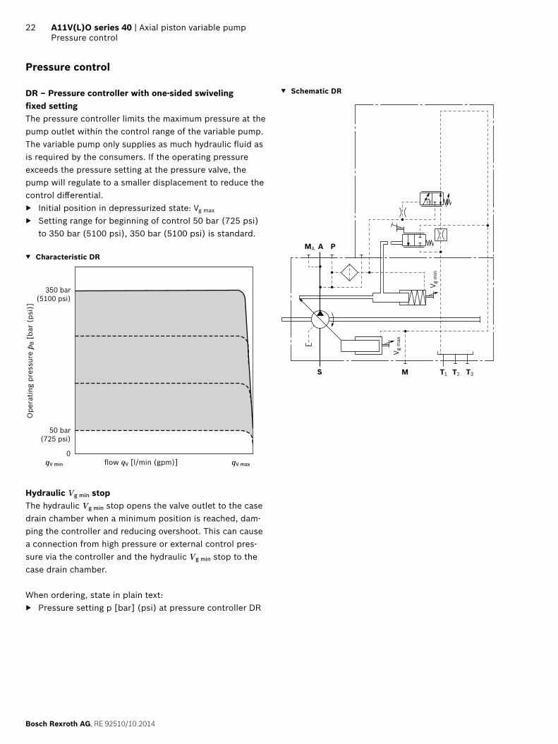
DR – Pressure controller with one-sided swivelingfi xed settingThe pressure controller limits the maximum pressure at the pump outlet within the control range of the variable pump. The variable pump only supplies as much hydraulic fl uid as is required by the consumers. If the operating pressure exceeds the pressure setting at the pressure valve, the pump will regulate to a smaller displacement to reduce the control diff erential.
Initial position in depressurized state: Vg max
Setting range for beginning of control 50 bar (725 psi) to 350 bar (5100 psi), 350 bar (5100 psi) is standard.
Characteristic DR
qV min fl ow qV [l/min (gpm)] qV max
Ope
ratin
g pr
essu
re p
B [
bar
(psi
)]
350 bar(5100 psi)
0
50 bar(725 psi)
Hydraulic Vg min stop The hydraulic Vg min stop opens the valve outlet to the case drain chamber when a minimum position is reached, dam-ping the controller and reducing overshoot. This can cause a connection from high pressure or external control pres-sure via the controller and the hydraulic Vg min stop to the case drain chamber.
When ordering, state in plain text: Pressure setting p [bar] (psi) at pressure controller DR
Schematic DR
MA A P
S M T2 T3T1
V g m
in
V g m
ax

RE 92510/10.2014, Bosch Rexroth AG
Axial piston variable pump | A11V(L)O series 40 Pressure control
23
DRS0 – Pressure control with load sensingThe load sensing controller works as a load-pressure cont-rolled fl ow controller and adjusts the displacement of the pump to the volume required by the consumer.The fl ow of the pump is then dependent on the cross sec-tion of the external measuring orifi ce (1), which is located between the pump and the consumer. Below the setting of the pressure controller and within the control range of the pump, the fl ow is not dependent on the load pressure.As a rule, the measuring orifi ce is a separately located load sensing directional valve (control block). The position of the directional valve spool determines the opening cross section of the measuring orifi ce and thus the fl ow of the pump.The load sensing controller compares pressure before and after the sensing orifi ce and keeps the pressure drop (diff e-rential pressure Δp) across the orifi ce – and therefore the fl ow – constant.If the diff erential pressure Δp at the measuring orifi ce rises, the pump is swiveled back (toward Vg min). If the diff erential pressure Δp drops, the pump is swiveled out (toward Vg max) until equilibrium at the measuring orifi ce is restored.
Δpmeasuring orifi ce = ppump – pconsumer
Setting range for Δp 14 bar (200 psi) to 30 bar (435 psi) (please state in plain text)
Standard adjustment 14 bar (200 psi)
The stand-by pressure in zero-stroke operation (measuring orifi ce closed) is slightly higher than the Δp setting.
Characteristic: DRS0
qV min fl ow qV [l/min (gpm)] qV max
Ope
ratin
g pr
essu
re p
B [
bar
(psi
)]
350(5100 psi)
0
14(200 psi)
Hydraulic Vg min stop The hydraulic Vg min stop opens the valve outlet to the case drain chamber when a minimum position is reached, dam-ping the controller and reducing overshoot. This can cause a connection from high pressure or external control pres-sure via the controller and the hydraulic Vg min stop to the case drain chamber.
When ordering, state in plain text: Pressure setting p [bar] (psi) at pressure controller DR Diff erential pressure Δp [bar (psi)] at load sensing
controller S0
Schematic DRS0
1
X
MA A P
S M T2 T3T1
V g m
in
V g m
ax
1 The measuring orifi ce (control block) is not included in the scope of supply.

Bosch Rexroth AG, RE 92510/10.2014
24 A11V(L)O series 40 | Axial piston variable pumpPressure control
DG – Pressure control with one-sided defl ection, hydraulically remote controlled (positive control)The remote controlled pressure control has a fi xed-setting Δp value. A separately connected pressure relief valve at port X (1) enables the pressure control to be remotely controlled.
Setting range Δp 14 (200 psi) to 25 bar (365 psi) Recommended value 20 bar (290 psi) (standard) Control volume at X: approx. 1.6 l/min (0.42 gpm) (sta-
tic) at Δp 20 bar (290 psi)In addition a separately confi gured 2/2 directional valve (2) can be operated to start the pump with low operating pressure (standby pressure).Both functions can be used individually or in combination (see circuit diagram).The external valves are not included in the scope of supply.As a separate pressure relief valve (1) we recommend:
For DBD.6, see data sheet 25402
Hydraulic Vg min stop The hydraulic Vg min stop opens the valve outlet to the case drain chamber when a minimum position is reached, dam-ping the pressure controller and reducing overshoot. This can cause a connection from high pressure or external control pressure via the controller and the hydraulic Vg min stop to the case drain chamber.
Operating pressure p in bar (psi) (test pressure for DG) Diff erential pressure Δp in bar (psi) Drive speed n in rpm Maximum fl ow qV max in l/min (gpm)
Note for setting remote controlled pressure controlThe setting value for the external pressure relief valve plus the diff erential pressure value at the pressure control valve determines the level of pressure control.Example:
external pressure relief valve 330 bar (4800 psi) Diff erential pressure at pressure
control valve 20 bar (290 psi) resulting pressure control with 330 + 20 = 350 bar
(4810 + 290 = 5100 psi)
Characteristic DG
qV min fl ow qV [l/min (gpm)] qV max
Ope
ratin
g pr
essu
re p
B [
bar
(psi
)]
350(5100)
0
14(200)
Δp pressure control valve
For function and description of pressure control DR, see page 22.
Schematic DG
MA A P
S M T2 T3T1
X
(1)(2)
Vg min
Vg max
1 Pressure-relief valve (not included in the scope of supply)
2 2/2 directional valve (not included in the scope of supply)

RE 92510/10.2014, Bosch Rexroth AG
Axial piston variable pump | A11V(L)O series 40 Dimensions size 110
25Dimensions [mm (in)]
Dimensions size 110
LRDRS0 – Power controller with pressure controller, load sensing and with electric swivel angle sensorWithout charge pump, clockwise rotation
113
(4.4
5)
233 (9.17)
285 (11.22)
4
123 (
4.84)
45°
27.8
(1.09
)
57.2(2.25)
50.8
(2.0
0)
88.9(3.50)
161.
6 (6
.36)
161.6 (6.36)
199.
6 (7
.86)
199.6 (7.86)
62.3(2.45)
25 (0.98)
20.6
(0.81
)
37 (1.46)6 (0.24)
123.5(4.86)
93(3
.66)45
°
11
(0.43
)
102
(4.0
1)
ø152
.4-0
.05
6.00
05.
998
(DIA
)
100(3.94)
242 (9.53) (P, T3)
187 (7.36)
237 (9.33)
117
(4.6
0)15
4.1
(6.0
7)
12.7-0.5 ( )0.500.48
101.5 (4.00)
120 (4.72)
34 (1.34)
104
(4.0
9)
164.
3 (6
.47)
180.
2 (7
.09)
144.8 (5.70)1)
W
X
T2 S
A
T1 A
T1
MA
M
P
X
X
MA
S
S
A
T3
T3
PA
Z
T2
11.8
1)
(0.4
6)1)
6.8
(0.2
7)1)
106.5 (4.19)(T3)
20 (0.79)
Detail X
Detail W
Detail Z
Flange D4SAE J744
1) Center of gravity

Bosch Rexroth AG, RE 92510/10.2014
26 A11V(L)O series 40 | Axial piston variable pumpDimensions size 110
Dimensions [mm (in)]
Splined shaft DIN 5480
A1 ‒ W45x2x21x9g
M16
x 2
1) 2
)
58 (2.28)
ø55
(DIA
2.1
7)
12(0.47)
32 (1.26)
50 (1.97)
42(1.65)
ø132
(D
IA 5
.19)
Ports - version “M” metric Standard Size2) pmax abs [bar (psi)]3) State7)
A Working line portFastening thread
SAE J5184)
DIN 131 inM12 × 2; 18 deep
420 (6100) O
S Suction port (without charge pump)Fastening thread
SAE J5184)
DIN 132 1/2 inM12 × 2; 18 deep
30 (435) O
T1 Drain port ISO 61495) M33 × 2; 19 deep 10 (145) O6)
T2 Drain port ISO 61495) M33 × 2; 19 deep 10 (145) X6)
T3 Drain port ISO 61495) M33 × 2; 19 deep 10 (145) X6)
CR Pilot signal (CR only) ISO 6149 M14 × 1.5; 11.5 deep 420 (6100) O
PR Pilot signal (PR only) ISO 6149 M14 × 1.5; 11.5 deep 420 (6100) O
H3, H4 Pilot signal (H3 and H4 only) ISO 6149 M14 × 1.5; 11.5 deep 100 (1450) O
L5, L6 Override power control(only with L5 and L6)
ISO 6149 M14 × 1.5; 11.5 deep 100 (1450) O
X Pilot signal (S0 and DG only) ISO 61495) M14 × 1.5; 11.5 deep 420 (6100) O
M Measuring, control pressure ISO 61495) M14 × 1.5; 12 deep 420 (6100) X
MA Measuring, pressure A ISO 61495) M14 × 1.5; 12 deep 420 (6100) X
P External control pressure(Ordering code digit 8 version B or C = with external control pressure supply)
ISO 61495) M14 × 1.5; 11.5 deep 50 (725) O
Port P without function(Ordering code digit 8 version A = without external control pressure supply)
ISO 61495) M18 × 1.5; 14.5 deep 420 (6100) X
1) Center bore according to DIN 332 (thread according to DIN 13)2) Observe the instructions in the operating instructions concerning
the maximum tightening torques.3) Depending on the application, momentary pressure spikes can occur.
Keep this in mind when selecting measuring equipment and fi ttings.4) Metric fastening thread is a deviation from standard
5) The spot face can be deeper than as specifi ed in the standard.6) Depending on installation position, T1, T2 or T3 must be connected
(see also installation instructions on pages 63 and 64).7) O = Must be connected (plugged on delivery)
X = Plugged (in normal operation)

RE 92510/10.2014, Bosch Rexroth AG
Axial piston variable pump | A11V(L)O series 40 Dimensions size 110
27Dimensions [mm (in)]
1) Involute spline according to ANSI B92.1a, 30° pressure angle, fl at root, side fi t, tolerance class 5
2) Centering bore according to ASME B1.13) Observe the instructions in the operating instructions concerning
the maximum tightening torques.4) Depending on the application, momentary pressure spikes can occur.
Keep this in mind when selecting measuring equipment and fi ttings.
5) The spot face can be deeper than as specifi ed in the standard.6) Depending on installation position, T1, T2 or T3 must be connected
(see also installation instructions on pages 63 and 64).7) O = Must be connected (plugged on delivery)
X = Plugged (in normal operation)
Splined shaft SAE J744
T1 ‒ 1 3/4 in 13T 8/16 DP1)
M16
x 2
1) 2
)
58 (2.28)
ø55
(DIA
2.1
7)
12(0.47)
32 (1.26)
50 (1.97)
42(1.65)
ø132
(D
IA 5
.19)
Ports - version “A” SAE Standard Size3) pmax abs [bar (psi)]4) State7)
A Working line portFastening thread
SAE J518ASME B1.1
1 in7/16-14UNC-2B; 19 (0.75) deep
420 (6100) O
S Suction port (without charge pump)Fastening thread
SAE J518ASME B1.1
2 1/2 in1/2-13UNC-2B; 19 (0.75) deep
30 (435) O
T1 Drain port ISO 119265) 1 5/16UNF-2B; 20 (0.79) deep 10 (145) O6)
T2 Drain port ISO 119265) 1 5/16UNF-2B; 20 (0.79) deep 10 (145) X6)
T3 Drain port ISO 119265) 1 5/16UNF-2B; 20 (0.79) deep 10 (145) X6)
CR Pilot signal (CR only) ISO 11926 9/16-18 UNF-2B; 13 (0.51) deep 420 (6100) O
PR Pilot signal (PR only) ISO 11926 9/16-18 UNF-2B; 13 (0.51) deep 420 (6100) O
H3, H4 Pilot signal (H3 and H4 only) ISO 11926 9/16-18 UNF-2B; 13 (0.51) deep 100 (1450) O
L5, L6 Override power control(only with L5 and L6)
ISO 11926 9/16-18 UNF-2B; 13 (0.51) deep 100 (1450) O
X Pilot signal (S0 and DG only) ISO 119265) 9/16-18 UNF-2B; 13 (0.51) deep 420 (6100) O
M Measuring, control pressure ISO 119265) 9/16-18 UNF-2B; 13 (0.51) deep 420 (6100) X
MA Measuring, pressure A ISO 119265) 9/16-18 UNF-2B; 13 (0.51) deep 420 (6100) X
P External control pressure(Ordering code digit 8 version B or C = with external control pressure supply)
ISO 119265) 9/16-18 UNF-2B; 13 (0.51) deep 50 (725) O
Port P without function(Ordering code digit 8 version A = without external control pressure supply)
ISO 119265) 3/4-16 UNF-2B; 12.6 (0.50) deep 420 (6100) X
Bosch Rexroth AG, RE 92510/10.2014
28 A11V(L)O series 40 | Axial piston variable pumpDimensions size 110
Dimensions [mm (in)]
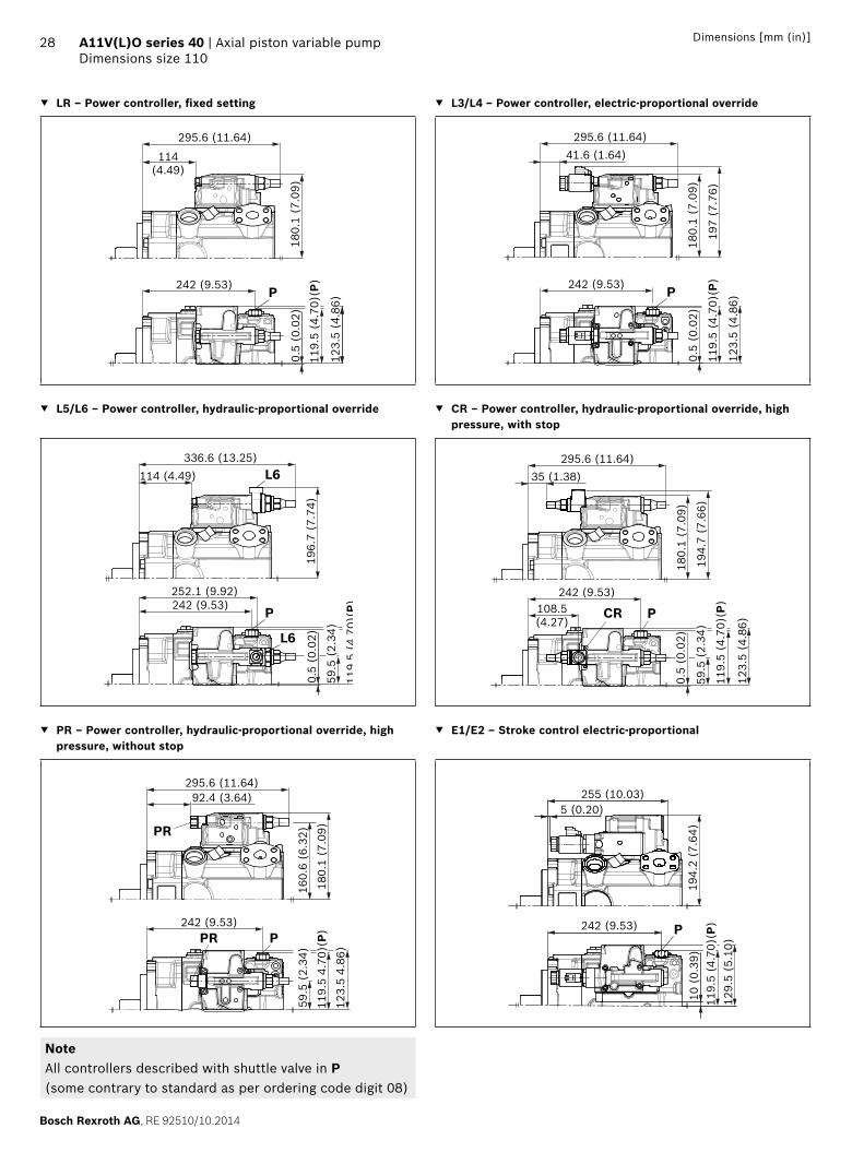
LR – Power controller, fi xed setting L3/L4 – Power controller, electric-proportional override
123.
5 (4
.86)
242 (9.53)0.
5 (0
.02)
180.
1 (7
.09)
119.
5 (4
.70)
(P)
295.6 (11.64)
114(4.49)
P P
123.
5 (4
.86)
242 (9.53)
0.5
(0.0
2)18
0.1
(7.0
9)
119.
5 (4
.70)
(P)
295.6 (11.64)41.6 (1.64)
197
(7.7
6)
L5/L6 – Power controller, hydraulic-proportional override CR – Power controller, hydraulic-proportional override, high pressure, with stop
242 (9.53)252.1 (9.92)
0.5
(0.0
2)19
6.7
(7.7
4)
119
5(4
70)(
P)
59.5
(2.
34)
336.6 (13.25)114 (4.49)
P
L6
L6
123.
5 (4
.86)
242 (9.53)
0.5
(0.0
2)18
0.1
(7.0
9)
119.
5 (4
.70)
(P)
295.6 (11.64)35 (1.38)
59.5
(2.
34)
194.
7 (7
.66)
108.5(4.27)
PCR
PR – Power controller, hydraulic-proportional override, high pressure, without stop
E1/E2 – Stroke control electric-proportional
242 (9.53)
160.
6 (6
.32)
180.
1 (7
.09)
92.4 (3.64)295.6 (11.64)
PR
119.
5 4.
70)(
P)59
.5 (
2.34
)
123.
5 4.
86)
PPR
5 (0.20)255 (10.03)
194.
2 (7
.64)
10 (
0.39
)11
9.5
(4.7
0)(P
)12
9.5
(5.1
0)
242 (9.53) P
NoteAll controllers described with shuttle valve in P(some contrary to standard as per ordering code digit 08)

RE 92510/10.2014, Bosch Rexroth AG
Axial piston variable pump | A11V(L)O series 40 Dimensions size 110
29Dimensions [mm (in)]
H3/H4 – Stroke control, hydraulic-proportional, pilot pressure DR – Pressure controller, fi xed setting
29.5(1.16)
76.5 (3.01)
131.
2(5
.17)
10 (
0.39
)
119.
5 (4
.70)
(P)
129.
5 (5
.10)
242 (9.53)
275.9 (10.86)
194.
2 (7
.65)
35 (
1.38
)
P
H3, H4
123.
5 (4
.86)
242 (9.53)
0.5
(0.0
2)18
0.1
(7.0
9)
119.
5 (4
.70)
(P)
275.9 (10.86)114 (4.49)
P
LRDRS0 – Power controller with pressure controller and load sensing, fi xed setting
DG – Pressure controller, hydraulic, remote controlled
123.
5 (4
.86)
242 (9.53)
187 (7.36)
0.5
(0.0
2)
101.
5 (3
.99)
180.
1 (7
.09)
119.
5 (4
.79)
(P)
295.6 (11.64)114 (4.49)
PX
242 (9.53)187 (7.36)
123.
5(4
.86)
0.5
(0.0
2)
119.
5 (4
.70)
(P)
180.
1 (7
.09)
101.
5 (3
.99)
275.9 (10.86)114 (4.49)
PX
NoteAll controllers described with shuttle valve in P (some contrary to standard as per ordering code digit 08)

Bosch Rexroth AG, RE 92510/10.2014
30 A11V(L)O series 40 | Axial piston variable pumpDimensions size 145
Dimensions [mm (in)]
Dimensions size 145
LRDRS0 – Power controller with pressure controller, load sensing and with electric swivel angle sensorWithout charge pump, clockwise rotation
123.
3 (4
.85)
186.
4 (7
.34)
252 (9.92)
310 (12.20)
4.7(0.19)
133.5
(5.26
)
45°
31.8
(1.25
)
66.7(2.63)
61.9
(2.4
4)
106.4(4.19)
161.
6 (6
.36)
161.6 (6.36)
199.
6 (7
.86)
199.6 (7.86)
74.6(2.94)
30 (1.18)
20.6
(0.81
)
40.4(1.59)
3 (0.12)
129.5(5.10)
98.6
(3.8
8)
131.55.18)
45°
12.2
0.48)
109.
9(4
.33)
5.99
8
ø152
.4-0
.05
6.00
0(D
IA
)
112.7(4.44)
267.7 (10.54)(T3)
203.9 (8.03)
256.5 (10.10)
125
(4.9
2)16
1.6
(6.3
6)
12.7-0.5 ( )0.480.50
107.5 (4.23)
34 (1.34)
170.
5 (6
.71)
265.5 (10.45)(P)
114
(4.4
9)
115.5 (4.55)(T3)
W
X
T2S
A
T1 A
T1
MA
M
P
X
X
MA
S
S
A
Z
T2
T3
P
T3
A
9.31)
(0.3
7)1)
158.1 (6.22)1)
6.3
(0.2
5)1)
22 (0.87)
Detail X
Detail W
Detail Z
Flange D4SAE J744
1) Center of gravity

RE 92510/10.2014, Bosch Rexroth AG
Axial piston variable pump | A11V(L)O series 40 Dimensions size 145
31Dimensions [mm (in)]
LRDRS0 – Power controller with pressure controller, load sensing and with electric swivel angle sensorWith charge pump, clockwise rotation
4.7(0.19)
133.5
(5.25
)
45°
161.
6 (6
.36)
161.6 (6.36)
199.
6 (7
.86)
199.6 (7.86)
75(2.95)
20.6
(0.81
)
21 (0.83)
45°
116.
5(4
.59)
ø152
.4-0
.05
107.5 (4.23)
170.
5 (6
.71)
125
(4.9
2)
122.5 (4.82)(T3)
31.8
(1.25
)
66.7(2.63)
61.9
(2.4
4)
106.4(4.19)
30 (1.18)
3 (0.12)
129.5(5.10)
98.6
(3.8
8)
131.55.18)
12.2
0.48)
5.99
8(D
IA
)
112.7(4.44)
203.9 (8.03)
256.5 (10.10)
161.
6 (6
.36)
12.7-0.5 ( )0.480.50
6.00
0
T1X
T1 A
X
MA
S
A
W
X
T2 S
A MA
M
PT3
5.71)
304.7 (11.99)358.7 (14.12)375.2 (14.77)
267.7 (10.54) (T3)
34 (1.34)
265.5 (10.45) (P)
Z
ST2
T3
PA
8.81)
(o.3
5)1)
188.4 (7.42)1)
123.
3 (4
.85)
186.
4 (7
.34)
114
(4.4
9)
22 (0.87)
Detail X
Detail W
Detail Z
Flange D4SAE J744
1) Center of gravity
Bosch Rexroth AG, RE 92510/10.2014
32 A11V(L)O series 40 | Axial piston variable pumpDimensions size 145
Dimensions [mm (in)]
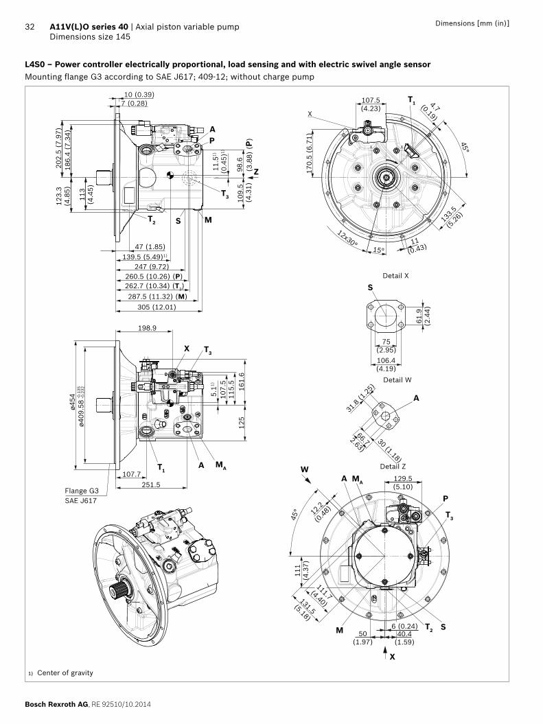
L4S0 – Power controller electrically proportional, load sensing and with electric swivel angle sensorMounting fl ange G3 according to SAE J617; 409-12; without charge pump
15°
12x30°
ø409
.58
-0.1
35-0
.232
45°
45°
125
123.
3(4
.85)
202.
5 (7
.97)
186.
4 (7
.34)
170.
5 (6
.71)
107.5(4.23)
133.5
(5.26
)
4.7(0.19)
11(0.43)
113
(4.4
5)
111
(4.3
7)
40.4(1.59)
6 (0.24)50
(1.97)
129.5(5.10)
131.5(5.18)
111.7(4.40)
12.2
(0.48
)
115.
510
7.5
198.9
161.
6
ø454
107.7251.5
X
31.8
(1.25
)
66.72.63)
61.9
(2.4
4)
106.4(4.19)
75(2.95)
30 (1.18)
109.
5 (4
.31)
98.6
(3.8
8) (
P)
S
A
M
A MA
S
P
T3
T2
X
W
T3
M
PA
Z11.5
1)
(0.4
5)1)
5.11)
247 (9.72)
305 (12.01)
262.7 (10.34) (T3)
47 (1.85)
287.5 (11.32) (M)
260.5 (10.26) (P)
ST2
T3X
AT1MA
T1
139.5 (5.49)1)
10 (0.39)7 (0.28)
Detail X
Detail W
Detail Z
Flange G3SAE J617
1) Center of gravity

RE 92510/10.2014, Bosch Rexroth AG
Axial piston variable pump | A11V(L)O series 40 Dimensions size 145
33Dimensions [mm (in)]
Splined shaft SAE J744
T1 ‒ 1 3/4 in 13T 8/16DP1) T2 ‒ 2 in 15T 8/16 DP1)
75 (2.95)
32(1.26)
53 (2.09)
1/2-
13U
NC
-2B
2) 4
)
ø60
(DIA
2.3
6)
67 (2.64)
10(0.39)
ø132
(D
IA 5
.20)
88 (3.46)
36(1.42)
66 (2.60)
5/8-
11U
NC
-2B
2) 4
)
ø60
(DIA
2.3
6)
80 (3.15)
12
ø132
(D
IA 5
.20)
Splined shaft DIN 5480
A2 ‒ W50x2x24x9g
M16
x 2
(3)
4)
63 (2.48)
ø60
(2.3
6)
12(0.47)
36(1.42)
55(0.22)
44(1.73)
ø132
(D
IA 5
.20)
1) Involute spline according to ANSI B92.1a, 30° pressure angle, fl at root, side fi t, tolerance class 5
2) Thread according to ASME B1.13) Center bore according to DIN 332 (thread according to DIN 13)4) Observe the instructions in the operating instructions concerning
the maximum tightening torques.
Bosch Rexroth AG, RE 92510/10.2014
34 A11V(L)O series 40 | Axial piston variable pumpDimensions size 145
Dimensions [mm (in)]
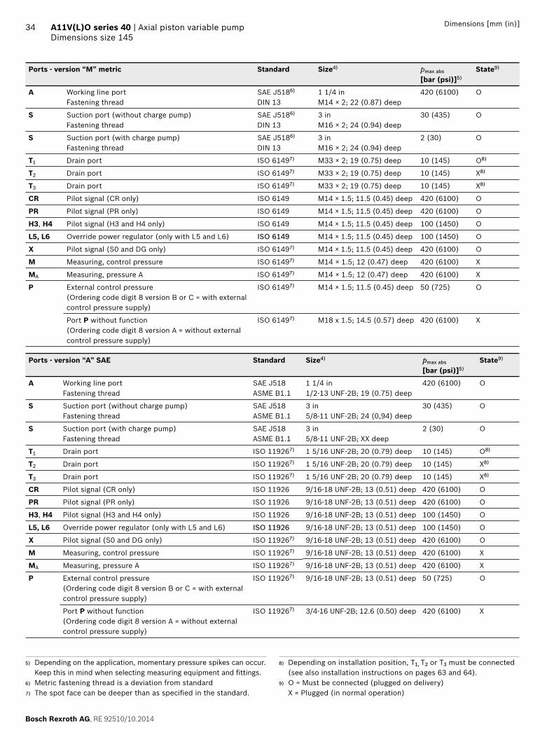
Ports - version “M” metric Standard Size4) pmax abs
[bar (psi)]5)State9)
A Working line portFastening thread
SAE J5186)
DIN 131 1/4 inM14 × 2; 22 (0.87) deep
420 (6100) O
S Suction port (without charge pump)Fastening thread
SAE J5186)
DIN 133 inM16 × 2; 24 (0.94) deep
30 (435) O
S Suction port (with charge pump)Fastening thread
SAE J5186)
DIN 133 inM16 × 2; 24 (0.94) deep
2 (30) O
T1 Drain port ISO 61497) M33 × 2; 19 (0.75) deep 10 (145) O8)
T2 Drain port ISO 61497) M33 × 2; 19 (0.75) deep 10 (145) X8)
T3 Drain port ISO 61497) M33 × 2; 19 (0.75) deep 10 (145) X8)
CR Pilot signal (CR only) ISO 6149 M14 × 1.5; 11.5 (0.45) deep 420 (6100) O
PR Pilot signal (PR only) ISO 6149 M14 × 1.5; 11.5 (0.45) deep 420 (6100) O
H3, H4 Pilot signal (H3 and H4 only) ISO 6149 M14 × 1.5; 11.5 (0.45) deep 100 (1450) O
L5, L6 Override power regulator (only with L5 and L6) ISO 6149 M14 × 1.5; 11.5 (0.45) deep 100 (1450) O
X Pilot signal (S0 and DG only) ISO 61497) M14 × 1.5; 11.5 (0.45) deep 420 (6100) O
M Measuring, control pressure ISO 61497) M14 × 1.5; 12 (0.47) deep 420 (6100) X
MA Measuring, pressure A ISO 61497) M14 × 1.5; 12 (0.47) deep 420 (6100) X
P External control pressure (Ordering code digit 8 version B or C = with external control pressure supply)
ISO 61497) M14 × 1.5; 11.5 (0.45) deep 50 (725) O
Port P without function(Ordering code digit 8 version A = without external control pressure supply)
ISO 61497) M18 x 1.5; 14.5 (0.57) deep 420 (6100) X
Ports - version “A” SAE Standard Size4) pmax abs
[bar (psi)]5)State9)
A Working line portFastening thread
SAE J518ASME B1.1
1 1/4 in1/2-13 UNF-2B; 19 (0.75) deep
420 (6100) O
S Suction port (without charge pump)Fastening thread
SAE J518ASME B1.1
3 in5/8-11 UNF-2B; 24 (0,94) deep
30 (435) O
S Suction port (with charge pump)Fastening thread
SAE J518ASME B1.1
3 in5/8-11 UNF-2B; XX deep
2 (30) O
T1 Drain port ISO 119267) 1 5/16 UNF-2B; 20 (0.79) deep 10 (145) O8)
T2 Drain port ISO 119267) 1 5/16 UNF-2B; 20 (0.79) deep 10 (145) X8)
T3 Drain port ISO 119267) 1 5/16 UNF-2B; 20 (0.79) deep 10 (145) X8)
CR Pilot signal (CR only) ISO 11926 9/16-18 UNF-2B; 13 (0.51) deep 420 (6100) O
PR Pilot signal (PR only) ISO 11926 9/16-18 UNF-2B; 13 (0.51) deep 420 (6100) O
H3, H4 Pilot signal (H3 and H4 only) ISO 11926 9/16-18 UNF-2B; 13 (0.51) deep 100 (1450) O
L5, L6 Override power regulator (only with L5 and L6) ISO 11926 9/16-18 UNF-2B; 13 (0.51) deep 100 (1450) O
X Pilot signal (S0 and DG only) ISO 119267) 9/16-18 UNF-2B; 13 (0.51) deep 420 (6100) O
M Measuring, control pressure ISO 119267) 9/16-18 UNF-2B; 13 (0.51) deep 420 (6100) X
MA Measuring, pressure A ISO 119267) 9/16-18 UNF-2B; 13 (0.51) deep 420 (6100) X
P External control pressure(Ordering code digit 8 version B or C = with external control pressure supply)
ISO 119267) 9/16-18 UNF-2B; 13 (0.51) deep 50 (725) O
Port P without function(Ordering code digit 8 version A = without external control pressure supply)
ISO 119267) 3/4-16 UNF-2B; 12.6 (0.50) deep 420 (6100) X
5) Depending on the application, momentary pressure spikes can occur. Keep this in mind when selecting measuring equipment and fi ttings.
6) Metric fastening thread is a deviation from standard7) The spot face can be deeper than as specifi ed in the standard.
8) Depending on installation position, T1, T2 or T3 must be connected (see also installation instructions on pages 63 and 64).
9) O = Must be connected (plugged on delivery) X = Plugged (in normal operation)

RE 92510/10.2014, Bosch Rexroth AG
Axial piston variable pump | A11V(L)O series 40 Dimensions size 145
35Dimensions [mm (in)]
LR – Power controller, fi xed setting L3/L4 – Power controller, electric-proportional override
130
(5.1
2) (
P)
265.5 (10.45)5.
5 (0
.21)
186.
4 (7
.34)
129.
5 (5
.10)
312.5 (12.30)130.9(5.15)
P
130
(5.1
2) (
P)
265.5 (10.45)
5.5
(0.2
2)18
6.4
(7.3
4)
129.
5 (5
.10)
312.5 (12.30)
58.5(2.30)
203.
2 (8
.00)
P
L5/L6 – Power controller, hydraulic override CR – Power controller, hydraulic-proportional override, high pressure, with stop
130
(5.1
2) (
P)
265.5 (10.45)269 (10.59)
5.5
(0.2
2)20
2.9
(7.9
9)
129.
5 (5
.10)
59.5
(2.
34)
353.5 (13.92)130.9(5.15)
P
L6
L6
130
(5.1
2) (
P)
265.5 (10.45)
5.5
(0.2
2)18
6.4
(7.3
4)
129.
5 (5
.10)
312.5 (12.30)51.9 (2.04)
65.5
(2.
58)
200.
9 (7
.91)
125.4(4.94)
PCR
PR – Power controller, hydraulic-proportional override, high pressure, without stop
E1/E2 – Stroke control electric-proportional
130
(5.1
2) (
P)
265.5 (10.45)
5.5
(0.2
2)
186.
4 (7
.34)
65.5
(2.
58)
312.5 (12.30)109.3(4.30)
166.
8 (6
.57)
129.
5 (5
.10)PPR
PR
21.9 (0.86)271.9 (10.70)
200.
4 (7
.89)
16 (
0.63
)
130
(5.1
2) (
P)
135.
5 (5
.33)
265.5 (10.45) P
NoteAll controllers described with shuttle valve in P (some contrary to standard as per ordering code digit 08)
Bosch Rexroth AG, RE 92510/10.2014
36 A11V(L)O series 40 | Axial piston variable pumpDimensions size 145
Dimensions [mm (in)]
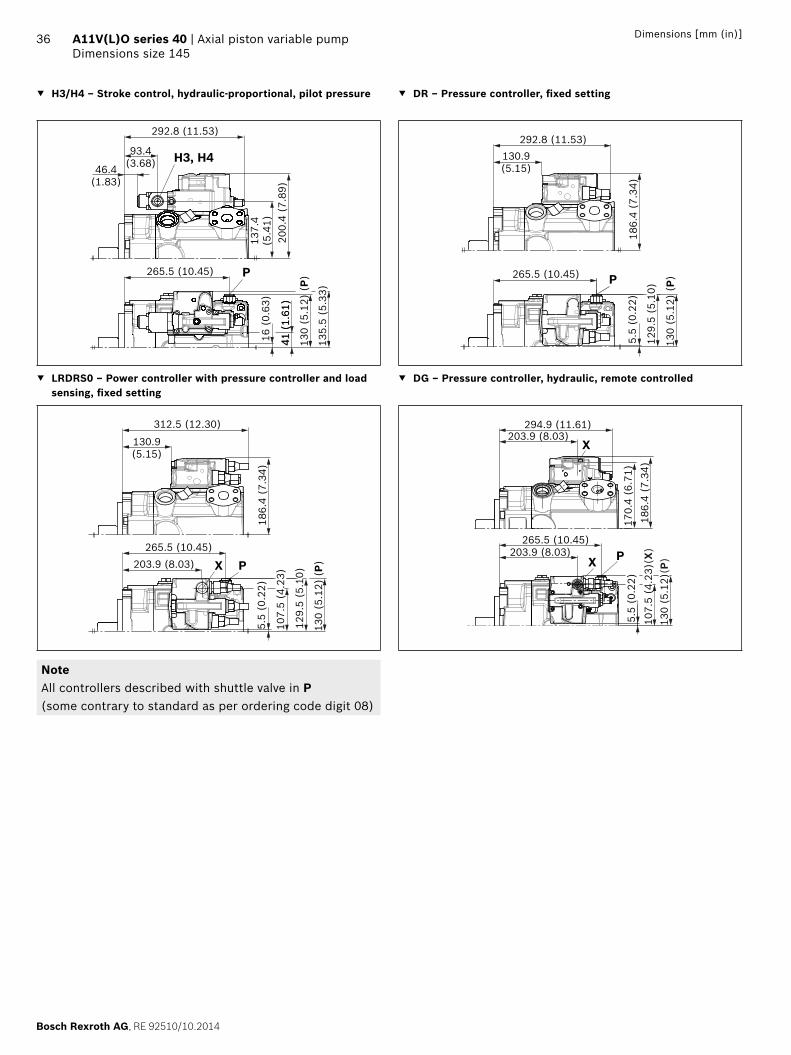
H3/H4 – Stroke control, hydraulic-proportional, pilot pressure DR – Pressure controller, fi xed setting
46.4(1.83)
93.4(3.68)
137.
4(5
.41)
16 (
0.63
)
130
(5.1
2) (
P)
135.
5 (5
.33)
265.5 (10.45)
292.8 (11.53)
200.
4 (7
.89)
41 (
1.61
)41
(1.
61)
P
H3, H4
130
(5.1
2) (
P)
265.5 (10.45)
5.5
(0.2
2)18
6.4
(7.3
4)
129.
5 (5
.10)
292.8 (11.53)130.9(5.15)
P
LRDRS0 – Power controller with pressure controller and load sensing, fi xed setting
DG – Pressure controller, hydraulic, remote controlled
130
(5.1
2) (
P)
265.5 (10.45)203.9 (8.03)
5.5
(0.2
2)
107.
5 (4
.23)
186.
4 (7
.34)
129.
5 (5
.10)
312.5 (12.30)
130.9(5.15)
PX
170.
4 (6
.71)
186.
4 (7
.34)
203.9 (8.03)294.9 (11.61)
265.5 (10.45)203.9 (8.03)
5.5
(0.2
2)10
7.5
(4.2
3)(X
)13
0 (5
.12)
(P)
X
X P
NoteAll controllers described with shuttle valve in P (some contrary to standard as per ordering code digit 08)
RE 92510/10.2014, Bosch Rexroth AG
Axial piston variable pump | A11V(L)O series 40 Dimensions size 175
37Dimensions [mm (in)]
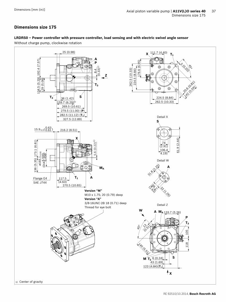
Dimensions size 175
LRDRS0 – Power controller with pressure controller, load sensing and with electric swivel angle sensorWithout charge pump, clockwise rotation
P
T3
A
129
(5.0
8)19
2.4
(7.5
7)
25 (0.98)
269.5 (10.61)
327.5 (12.89)
5 (0.20)
142 (
5.59)
45°
31.8
(1.25
)
66.7(2.63)
61.9
(2.
44)
106.44.19)
224.
5 (8
.84)
224.5 (8.84)
262.
5 (1
0.33
)
262.5 (10.33)
74(2.91)
32 (1.26)
20.6
(0.81
)
43 (1.69)6 (0.24)
133.7 (5.26)
105
140 (5.51)
45° 13
(0.51
)
118
ø165
.1-0
.05
6.50
06.
498
(DIA
)
117.5(4.63)
282.5 (11.12) (T3)
216.2 (8.51)
270.5 (10.65)
136
(5.3
5)17
3.1
(6.8
1)
15.9-0.5( )0.610.63
111.7 (4.40)
T3
123 (4.84)(T3)
176.
6 (6
.95)
36 (1.42)
134.
5 (5
.29)
W
X
T2S
A
T1 A
T1
MA
M
P
X
X
MA
S
S
A
Z
T28.
4(0
.33)
1)5.
6 (0
.22)
1)
159.7 (6.29)1)
279.5 (11.00) (P)
Detail X
Detail W
Detail Z
Version “M”M10 x 1.75; 20 (0.79) deepVersion “A”3/8-16UNC-2B 18 (0.71) deepThread for eye bolt
Flange E4SAE J744
1) Center of gravity

Bosch Rexroth AG, RE 92510/10.2014
38 A11V(L)O series 40 | Axial piston variable pumpDimensions size 175
Dimensions [mm (in)]
LRDRS0 – Power controller with pressure controller, load sensing and with electric swivel angle sensorWith charge pump, clockwise rotation
129
(5.0
8)
36 (1.42)
134.
5 (5
.29)
192.
4 (7
.57)
25 (0.98)
317.5 (12.50)
4 (0.16)
142 (
(5.59
)
45°
31.8
(1.25
)
66.7(2.63)
69.9
(2.7
5)
120.7(4.75)
224.
5 (8
.84)
224.5 (8.84)
262.
5 (1
0.33
)
90(3.54)
32 (1.26)
32 (1.26)
20.6
(0.81
)
22 (0.87)
6 (0.24)
133.7 (5.26)
105
(4.1
3)
140 (5.51)
45° 13
(0.51
)
125
(4.2
9)
6.49
86.
500
(DIA
)
ø165
.1-0
.05
117.5(4.63)
270.5 (10.65)
136
(5.3
5)17
3.1
(6.8
1)
111.7 (4.40)
376.5 (14.82)394.5 (15.53)
262.5 (10.33)
127 (5.00) (T3)
176.
6 (6
.95)
W
X
T2 S
A
T1 A
T1
MA
M
P
MA
S
S
A
X
X
T2
Z
216.2 (8.51)0.610.6315.9-0.5 ( )
7.1
(0.2
8)1)
183.9 (7.24)1)
5.5
(0.2
1)1)
T3
PA
T3
282.5 (11.12) (T3)279.5 (11.00) (P)
Detail X
Detail W
Detail Z
Flange E4SAE J744
1) Center of gravity
Version “M”M10 x 1.75; 20 (0.79) deepVersion “A”3/8-16UNC-2B 18 (0.71) deepThread for eye bolt

RE 92510/10.2014, Bosch Rexroth AG
Axial piston variable pump | A11V(L)O series 40 Dimensions size 175
39Dimensions [mm (in)]
LRDRS0 – Power controller with pressure controller, load sensing and without electric swivel angle sensorMounting fl ange G3 according to SAE J617; 409-12; without charge pump
31.8
(1.25
)
66.7(2.63)32 (1.26)
32 (1.26)
111.7(4.40)
X
X
P
ST2M
WA MA
A
ST2
T1
M
P
T3
T3
195.
4 (7
.69)
69.7
(2.
74)
29.7
(1.
17)
113.
7 (4
.48)
131.
2 (5
.17)
211.2 (8.31)
123.
6(4
.87)
112.6(4.43)
265.6 (10.46)
133.
7(5
.26)
136
(5.3
5)
A MA
45°
179.
5 (7
.07)
133.7 (5.26)
4(0.16)
142.3
(5.60
)
11 (0.43)15°
12 x 30°
13
(0.51
)
45°
119 (4.69)
140 (5.51)
6 (0.24)43 (1.69)
53 (2.09)
110.5 (4.35)
117.
3
T1X
X
119.
3(4
.70)
105
(P)
7011
8.5
(S)
13 (0.51)274.6 (10.81) (P)277.6 (10.93) (T3)
47 (1.85)
303.6 (11.95)322.6 (12.70)
264.6 (10.42)
Ø40
9.58
16.1
2016
.116
(DIA
)
-0.1
35-0
.232
Ø45
4 (1
7.87
) 61.9
(2.
44)
106.44.19)
74(2.91)
S
0.2
(0.0
1)1)
113.5 (4.47)1)
0.2
(0.0
1)1)
Detail X
Detail W
Detail Z
Flange G3SAE J617
1) Center of gravity
Version “M”M10 x 1.75; 20 (0.79) deepVersion “A”3/8-16UNC-2B 18 (0.71) deepThread for eye bolt

Bosch Rexroth AG, RE 92510/10.2014
40 A11V(L)O series 40 | Axial piston variable pumpDimensions size 175
Dimensions [mm (in)]
Splined shaft SAE J744
T1 ‒ 1 3/4 in 13T 8/16DP1) T2 ‒ 2 in 15T 8/16DP1)
75 (2.95)
32(1.26)
53 (2.09)
1/2-
13U
NC
-2B
2) 4
)
ø60
(DIA
2.3
6)
67 (2.64)
10(0.39)
ø140
(D
IA 5
.51)
88 (3.46)
36(1.42)
66 (2.60)
5/8-
11U
NC
-2B
2) 4
)
ø60
(DIA
2.3
6)
80 (3.15)
12(0.47)
ø140
(D
IA 5
.51)
Splined shaft DIN 5480
A2 ‒ W50x2x24x9g
M16
x 2
(0.
08)3)
4)
62 (2.44)
ø60
(DIA
2.3
6)
12(0.47)
36(1.42)
54 (2.13)
45 (1.77)
ø140
(D
IA 5
.51)
1) Involute spline according to ANSI B92.1a, 30° pressure angle, fl at root, side fi t, tolerance class 5
2) Thread according to ASME B1.13) Center bore according to DIN 332 (thread according to DIN 13)4) Observe the instructions in the operating instructions concerning
the maximum tightening torques.
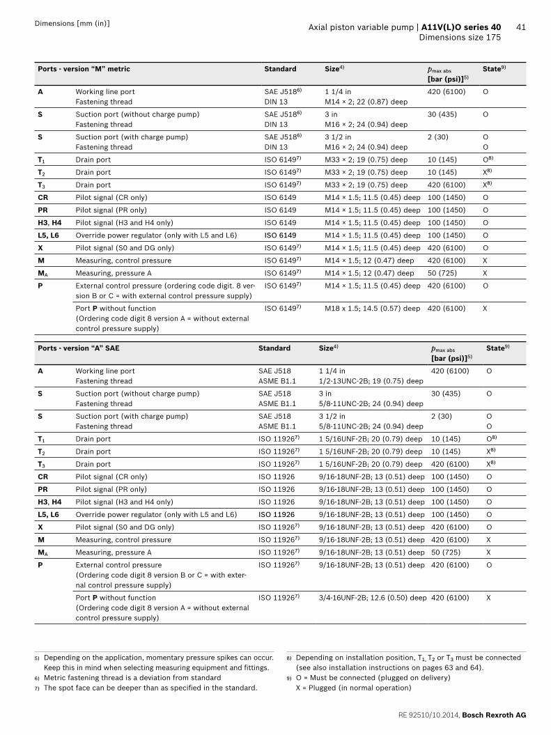
RE 92510/10.2014, Bosch Rexroth AG
Axial piston variable pump | A11V(L)O series 40 Dimensions size 175
41Dimensions [mm (in)]
Ports - version “M” metric Standard Size4) pmax abs
[bar (psi)]5)State9)
A Working line portFastening thread
SAE J5186)
DIN 131 1/4 inM14 × 2; 22 (0.87) deep
420 (6100) O
S Suction port (without charge pump)Fastening thread
SAE J5186)
DIN 133 inM16 × 2; 24 (0.94) deep
30 (435) O
S Suction port (with charge pump)Fastening thread
SAE J5186)
DIN 133 1/2 inM16 × 2; 24 (0.94) deep
2 (30) OO
T1 Drain port ISO 61497) M33 × 2; 19 (0.75) deep 10 (145) O8)
T2 Drain port ISO 61497) M33 × 2; 19 (0.75) deep 10 (145) X8)
T3 Drain port ISO 61497) M33 × 2; 19 (0.75) deep 420 (6100) X8)
CR Pilot signal (CR only) ISO 6149 M14 × 1.5; 11.5 (0.45) deep 100 (1450) O
PR Pilot signal (PR only) ISO 6149 M14 × 1.5; 11.5 (0.45) deep 100 (1450) O
H3, H4 Pilot signal (H3 and H4 only) ISO 6149 M14 × 1.5; 11.5 (0.45) deep 100 (1450) O
L5, L6 Override power regulator (only with L5 and L6) ISO 6149 M14 × 1.5; 11.5 (0.45) deep 100 (1450) O
X Pilot signal (S0 and DG only) ISO 61497) M14 × 1.5; 11.5 (0.45) deep 420 (6100) O
M Measuring, control pressure ISO 61497) M14 × 1.5; 12 (0.47) deep 420 (6100) X
MA Measuring, pressure A ISO 61497) M14 × 1.5; 12 (0.47) deep 50 (725) X
P External control pressure (ordering code digit. 8 ver-sion B or C = with external control pressure supply)
ISO 61497) M14 × 1.5; 11.5 (0.45) deep 420 (6100) O
Port P without function(Ordering code digit 8 version A = without external control pressure supply)
ISO 61497) M18 x 1.5; 14.5 (0.57) deep 420 (6100) X
Ports - version “A” SAE Standard Size4) pmax abs
[bar (psi)]5)State9)
A Working line portFastening thread
SAE J518ASME B1.1
1 1/4 in1/2-13UNC-2B; 19 (0.75) deep
420 (6100) O
S Suction port (without charge pump)Fastening thread
SAE J518ASME B1.1
3 in5/8-11UNC-2B; 24 (0.94) deep
30 (435) O
S Suction port (with charge pump)Fastening thread
SAE J518ASME B1.1
3 1/2 in5/8-11UNC-2B; 24 (0.94) deep
2 (30) OO
T1 Drain port ISO 119267) 1 5/16UNF-2B; 20 (0.79) deep 10 (145) O8)
T2 Drain port ISO 119267) 1 5/16UNF-2B; 20 (0.79) deep 10 (145) X8)
T3 Drain port ISO 119267) 1 5/16UNF-2B; 20 (0.79) deep 420 (6100) X8)
CR Pilot signal (CR only) ISO 11926 9/16-18UNF-2B; 13 (0.51) deep 100 (1450) O
PR Pilot signal (PR only) ISO 11926 9/16-18UNF-2B; 13 (0.51) deep 100 (1450) O
H3, H4 Pilot signal (H3 and H4 only) ISO 11926 9/16-18UNF-2B; 13 (0.51) deep 100 (1450) O
L5, L6 Override power regulator (only with L5 and L6) ISO 11926 9/16-18UNF-2B; 13 (0.51) deep 100 (1450) O
X Pilot signal (S0 and DG only) ISO 119267) 9/16-18UNF-2B; 13 (0.51) deep 420 (6100) O
M Measuring, control pressure ISO 119267) 9/16-18UNF-2B; 13 (0.51) deep 420 (6100) X
MA Measuring, pressure A ISO 119267) 9/16-18UNF-2B; 13 (0.51) deep 50 (725) X
P External control pressure(Ordering code digit 8 version B or C = with exter-nal control pressure supply)
ISO 119267) 9/16-18UNF-2B; 13 (0.51) deep 420 (6100) O
Port P without function(Ordering code digit 8 version A = without external control pressure supply)
ISO 119267) 3/4-16UNF-2B; 12.6 (0.50) deep 420 (6100) X
5) Depending on the application, momentary pressure spikes can occur. Keep this in mind when selecting measuring equipment and fi ttings.
6) Metric fastening thread is a deviation from standard7) The spot face can be deeper than as specifi ed in the standard.
8) Depending on installation position, T1, T2 or T3 must be connected (see also installation instructions on pages 63 and 64).
9) O = Must be connected (plugged on delivery) X = Plugged (in normal operation)

Bosch Rexroth AG, RE 92510/10.2014
42 A11V(L)O series 40 | Axial piston variable pumpDimensions size 175
Dimensions [mm (in)]
LR – Power controller, fi xed setting L3/L4 – Power controller, electric-proportional override
9.7
(0.3
8)19
2.4
(7.5
7)13
3.7
(5.2
6)279.5 (11.00)
134.
5 (5
.29)
(P)P
143.2(5.64)
324.8 (12.79)
143.
5 (5
.65)
9.7
(0.3
8)19
2.4
(7.5
7)
70.8 (2.79)
324.8 (12.79)
209.
3 (8
.24)
133.
7 (5
.26)
279.5 (11.00)
134.
5 (5
.29)
(P)P
143.
5 (5
.65)
L5/L6 – Power controller, hydraulic override CR – Power controller, hydraulic-proportional override, high pressure, with stop
9.7
(0.3
8)20
9 (8
.23)
133.
7 (5
.26)
69.7
(2.
74)
279.5 (11.00)281.3 (11.07) (L6)
134.
5 (5
.29)
(P)
L6
L6143.2(5.64)
365.8 (14.40)
143.
5 (5
.65)
9.7
(0.3
8)
143.
5 (5
.65)
192.
4 (7
.57)
133.
7 (5
.26)
137.7(5.42)
134.
5 (5
.29)
(P)
69.7
(2.
74)
207
(8.1
5)
279.5 (11.00)
PCR
64.2 (2.53)
324.8 (12.79)
PR – Power controller, hydraulic-proportional override, high pressure, without stop
E1/E2 – Stroke control electric-proportional
9.7
(0.3
8)17
2.9
(6.8
1)
121.6(4.79)
324.8 (12.79)
192.
4 (7
.57)
143.
5 (5
.65)
133.
7 (5
.26)
279.5 (11.00)
134.
5 (5
.29)
(P)
69.7
(2.
74)
PPR
PR
20.2
(0.
79)
134.
5 (5
.29)
(P)
139.
7 (5
.50)
206.
5 (8
.13)
279.5 (11.00)
284.2 (11.19)
34.2 (1.35)
P
143.
5 (5
.65)
NoteAll controllers described with shuttle valve in P (some contrary to standard as per ordering code digit 08)
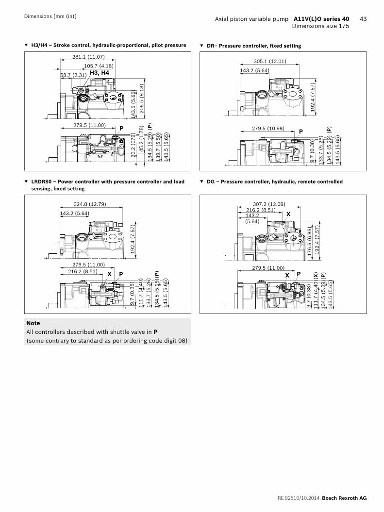
RE 92510/10.2014, Bosch Rexroth AG
Axial piston variable pump | A11V(L)O series 40 Dimensions size 175
43Dimensions [mm (in)]
H3/H4 – Stroke control, hydraulic-proportional, pilot pressure DR– Pressure controller, fi xed setting
45.2
(1.
78)
105.7 (4.16)
281.1 (11.07)
58.7 (2.31)
134.
5 (5
.29)
(P)
139.
7 (5
.50)
143.
5 (5
.65)
279.5 (11.00)20
.2 (
079)
206.
5 (8
.13)
P
H3, H4
143.
5 (5
.65)
192.
4 (7
.57)
133.
7 (5
.26)
279.5 (10.98)
134.
5 (5
.29)
(P)
9.7
(0.3
8)
P
143.2 (5.64)
305.1 (12.01)
143.
5 (5
.65)
LRDRS0 – Power controller with pressure controller and load sensing, fi xed setting
DG – Pressure controller, hydraulic, remote controlled
192.
4 (7
.57)
133.
7 (5
.26)
279.5 (11.00)216.2 (8.51)
111.
7 (4
.40)
134.
5 (5
.29)
(P)
9.7
(0.3
8)
PX
143.2 (5.64)
324.8 (12.79)
143.
5 (5
.65)
176.
5 (6
.95)
192.
4 (7
.57)
216.2 (8.51)143.2(5.64)
307.2 (12.09)
279.5 (11.00)
9.7
(0.3
8)11
1.7
(4.4
0)(X
)13
4.5
(5.2
9)(P
)
X
X P
143.
5 (5
.65)
NoteAll controllers described with shuttle valve in P (some contrary to standard as per ordering code digit 08)

Bosch Rexroth AG, RE 92510/10.2014
44 A11V(L)O series 40 | Axial piston variable pumpDimensions size 210
Dimensions [mm (in)]
Dimensions size 210
LRDRS0 – Power controller with pressure controller, load sensing and with electric swivel angle sensorWithout charge pump, clockwise rotation
137.
3 (5
.41)
200.
2 (7
.88)
25.8 (1.02)
282.5 (11.12)
344.8 (13.57)
8 (0.31)
152 (
5.98)
45°
36.5
(1.44
)
79.4(3.12)
69.9
(2.
75)
120.7(4.75)
224.
5 (8
.84)
224.5 (8.84)
262.
5 (1
0.33
)
262.5 (10.33)
90(3.54)
38 (1.50)
20.6
(0.81
)
45 (1.77)
138 (5.43)
109
(4.2
9)
148(5.83)
45°
18
(0.71
)
128
(5.0
4)
6.49
86.
500
(DIA
)
ø165
.1-0
.05
120(4.72)
299.6 (11.79) (T3)
230.7 (9.08)
285.6 (11.24)
142.
5 (5
.61)
178.
6 (7
.03)
0.600.6315.9-0.5 ( )
4.5 (0.18)
293.6 (11.56) (P)
130
(5.1
2)
184.
3 (7
.26)
127 (5.00)(T3)
W
X
T2 S
A
T1 A
T1
MA
M
P
X
X
MA
S
S
Z
T2
A
T3
PA
T3
116 (4.57)
7.81)
171.7 (6.76)1)
5.0
(0.2
0)1)
43.5 (1.71)
Detail X
Detail W
Detail Z
Version “M”M12 x 1.75; 22 (0.87) deepVersion “A”1/2-13UNC-2B; 22 (0.87) deepThread for eye bolt
Flange E4SAE J744
1) Center of gravity

RE 92510/10.2014, Bosch Rexroth AG
Axial piston variable pump | A11V(L)O series 40 Dimensions size 210
45Dimensions [mm (in)]
LRDRS0 – Power controller with pressure controller, load sensing and with electric swivel angle sensorWith charge pump, clockwise rotation
299.6 (11.79) (T3)293.6 (11.56)(P)
43.5 (1.71)
224.
5 (8
.84)
262.
5 (1
0.33
)
184.
3 (7
.26)
132 (5.20)(T3)
137.
3 (5
.41)
200.
2 (7
.88)
333.8 (13.14)
7 (0.27)
150 (
5.90)
45°
36.5
(1.44
)
79.4(3.12)69
.9(2
.75)
120.7(4.75)
224.5 (8.84)262.5 (10.33)
90(3.54)
38 (1.50)
20.6
(0.81
)
16 (0.63)
138 (5.43)
109
148(5.83)
45°
18
(0.71
)
135
6.49
8
ø165
.1-0
.05
6.50
0(D
IA
)
122(4.80)
285.6 (11.24)
142.
5 (5
.61)
178.
6 (7
.03)
0.600.6315.9-0.5 ( )
4.5 (0.18)
393.8 (15.50)411.8 (16.21)
116 (4.57)
6.9
(0.2
7)1)
230.7 (9.08)
25.8 (1.02)
W
X
T2 S
A
T1 A
T1
MA
M
P
X
X
MA
S
S
A
T3
PA
T3
T2
Z
4.3
(0.1
7)1)
195 (7.68)1)
130
(5.1
2)
Detail X
Detail W
Detail Z
Version “M”M12 x 1.75; 22 (0.87) deepVersion “A”1/2-13UNC-2B, 22 (0.87) deepThread for eye bolt
Flange E4SAE J744
1) Center of gravity
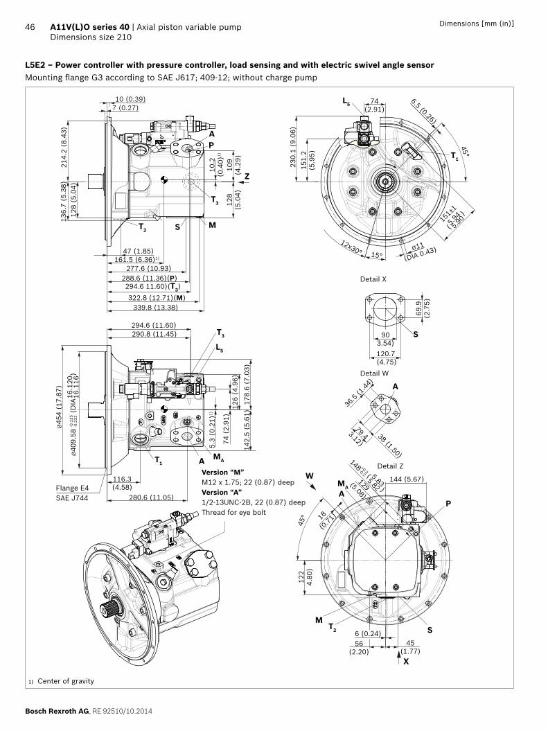
Bosch Rexroth AG, RE 92510/10.2014
46 A11V(L)O series 40 | Axial piston variable pumpDimensions size 210
Dimensions [mm (in)]
L5E2 – Power controller with pressure controller, load sensing and with electric swivel angle sensorMounting fl ange G3 according to SAE J617; 409-12; without charge pump
X
W
T3
L5
T1
PA
Z
M
A
S
AP
MA
T2
M
MA
ST2
T1
T3
L5
10 (0.39)7 (0.27)
15°
12x30°
45°
129(5.08)
151±
1
5.94
5.90
(
)
Ø40
9.58
16.1
2016
.116
(DIA
)
-0.1
35-0
.232
136.
7 (5
.38)
178.
6 (7
.03)
142.
5 (5
.61)
214.
2 (8
.43)
74 (
2.91
)
290.8 (11.45)
151.
2(5
.95)
230.
1 (9
.06)
74(2.91)
122
4.80
)
128
(5.0
4)10
9(4
.29)
144 (5.67)
56(2.20)
6 (0.24)45
(1.77)
18
(0.71
)
5.82
( )
5.83
148 +0.2-0.2
280.6 (11.05)
116.3(4.58)
294.6 (11.60)
126
(4.9
6)
45°
6.5 (0.26)
Ø11
(DIA 0.43)
Ø45
4 (1
7.87
)
288.6 (11.36)(P)294.6 11.60)(T3)
128
(5.0
4)
47 (1.85)
277.6 (10.93)
322.8 (12.71)(M)339.8 (13.38)
161.5 (6.36)1)
10.2
(0.4
0)1)
5.3
(0.2
1)1)
36.5
(1.44
)
79.43.12)
69.9
(2.7
5)
120.7(4.75)
903.54)
38 (1.50)
S
A
Detail X
Detail W
Detail ZVersion “M”M12 x 1.75; 22 (0.87) deepVersion “A”1/2-13UNC-2B, 22 (0.87) deepThread for eye bolt
Flange E4SAE J744
1) Center of gravity

RE 92510/10.2014, Bosch Rexroth AG
Axial piston variable pump | A11V(L)O series 40 Dimensions size 210
47Dimensions [mm (in)]
Splined shaft SAE J744
T1 ‒ 1 3/4 in 13T 8/16DP1) T2 ‒ 2 in 15T 8/16DP1)
75 (2.95)
32(1.26)
53 (2.09)
1/2-
13U
NC
-2B
2) 4
)
ø60
(DIA
2.3
6)
67 (2.64)
10(0.39)
ø140
(D
IA 5
.51)
88 (3.46)
36(1.42)
66 (2.60)
5/8-
11U
NC
-2B
2) 4
)
ø60
(DIA
2.3
6)
80 (3.15)
12(0.47)
ø140
(D
IA 5
.51)
Splined shaft DIN 5480
A2 ‒ W50x2x24x9g
M16
x 2
3) 4
)
62 (2.44)
ø60
(DIA
2.3
6)
12(0.47)
38(1.50)
54 (2.13)
45 (1.77)
ø140
(D
IA 5
.51)
1) Involute spline according to ANSI B92.1a, 30° pressure angle, fl at root, side fi t, tolerance class 5
2) Thread according to ASME B1.13) Center bore according to DIN 332 (thread according to DIN 13)4) Observe the instructions in the operating instructions concerning
the maximum tightening torques.

Bosch Rexroth AG, RE 92510/10.2014
48 A11V(L)O series 40 | Axial piston variable pumpDimensions size 210
Dimensions [mm (in)]
Ports - version “M” metric Standard Size4) pmax abs
[bar (psi)]5)State9)
A Working line portFastening thread
SAE J5186)
DIN 131 1/2 inM16 x 2; 24 (0.94) deep
420 (6100) O
S Suction port (without charge pump)Fastening thread
SAE J5186)
DIN 133 1/2 inM16 x 2; 24 (0.94) deep
30 (435) O
S Suction port (with charge pump)Fastening thread
SAE J5186)
DIN 133 1/2 inM16 x 2; 24 (0.94) deep
2 (30) O
T1 Drain port ISO 61497) M42 x 2; 19.5 (0.77) deep 10 (145) O8)
T2 Drain port ISO 61497) M42 x 2; 19.5 (0.77) deep 10 (145) X8)
T3 Drain port ISO 61497) M42 x 2; 19.5 (0.77) deep 10 (145) X8)
CR Pilot signal (CR only) ISO 6149 M14 x 1.5; 11.5 (0.45) deep 420 (6100) O
PR Pilot signal (PR only) ISO 6149 M14 x 1.5; 11.5 (0.45) deep 420 (6100) O
H3, H4 Pilot signal (H3 and H4 only) ISO 6149 M14 x 1.5; 11.5 (0.45) deep 100 (1450) O
L5, L6 Override power regulator (only with L5 and L6) ISO 6149 M14 x 1.5; 11.5 (0.45) deep 100 (1450) O
X Pilot signal (S0 and DG only) ISO 61497) M14 x 1.5; 11.5 (0.45) deep 420 (6100) O
M Measuring, control pressure ISO 61497) M14 x 1.5; 12 (0.47) deep 420 (6100) X
MA Measuring, pressure A ISO 61497) M14 x 1.5; 12 (0.47) deep 420 (6100) X
P External control pressure(Ordering code digit 8 version B or C = with external control pressure supply)
ISO 61497) M14 x 1.5; 11.5 (0.45) deep 50 (725) O
Port P without function(Ordering code digit 8 version A = without external control pressure supply)
ISO 61497) M18 x 1.5; 14.5 deep 420 (6100) X
Ports - version “A” SAE Standard Size4) pmax abs
[bar (psi)]5)State9)
A Working line portFastening thread
SAE J518ASME B1.1
1 1/2 in5/8-11UNC-2B; 30 (1.18) deep
420 (6100) O
S Suction port (without charge pump)Fastening thread
SAE J518ASME B1.1
3 1/2 in5/8-11UNC-2B; 30 (1.18) deep
30 (435) O
S Suction port (with charge pump)Fastening thread
SAE J5184)
ASME B1.13 1/2 in5/8-11UNC-2B; 30 (1.18) deep
2 (30) O
T1 Drain port ISO 119267) 1 5/8-12UNF-2B; 20 (0.79) deep 10 (145) O8)
T2 Drain port ISO 119267) 1 5/8-12UNF-2B; 20 (0.79) deep 10 (145) X8)
T3 Drain port ISO 119267) 1 5/8-12UNF-2B; 20 (0.79) deep 10 (145) X8)
CR Pilot signal (CR only) ISO 11926 9/16-18UNF-2B; 13 (0.51) deep 420 (6100) O
PR Pilot signal (PR only) ISO 11926 9/16-18UNF-2B; 13 (0.51) deep 420 (6100) O
H3, H4 Pilot signal (H3 and H4 only) ISO 11926 9/16-18UNF-2B; 13 (0.51) deep 100 (1450) O
L5, L6 Override power regulator (only with L5 and L6) ISO 11926 9/16-18UNF-2B; 13 (0.51) deep 100 (1450) O
X Pilot signal (S0 and DG only) ISO 119267) 9/16-18UNF-2B; 13 (0.51) deep 420 (6100) O
M Measuring, control pressure ISO 119267) 9/16-18UNF-2B; 13 (0.51) deep 420 (6100) X
MA Measuring, pressure A ISO 119267) 9/16-18UNF-2B; 13 (0.51) deep 420 (6100) X
P External control pressure(Ordering code digit 8 version B or C = with external control pressure supply)
ISO 119267) 9/16-18UNF-2B; 13 (0.51) deep 50 (725) O
Port P without function(Ordering code digit 8 version A = without external control pressure supply)
ISO 119267) 3/4-16UNF-2B; 12.6 (0.50) deep 420 (6100) X
5) Depending on the application, momentary pressure spikes can occur. Keep this in mind when selecting measuring equipment and fi ttings.
6) Metric fastening thread is a deviation from standard7) The spot face can be deeper than as specifi ed in the standard.
8) Depending on installation position, T1, T2 or T3 must be connected (see also installation instructions on pages 63 and 64).
9) O = Must be connected (plugged on delivery) X = Plugged (in normal operation)
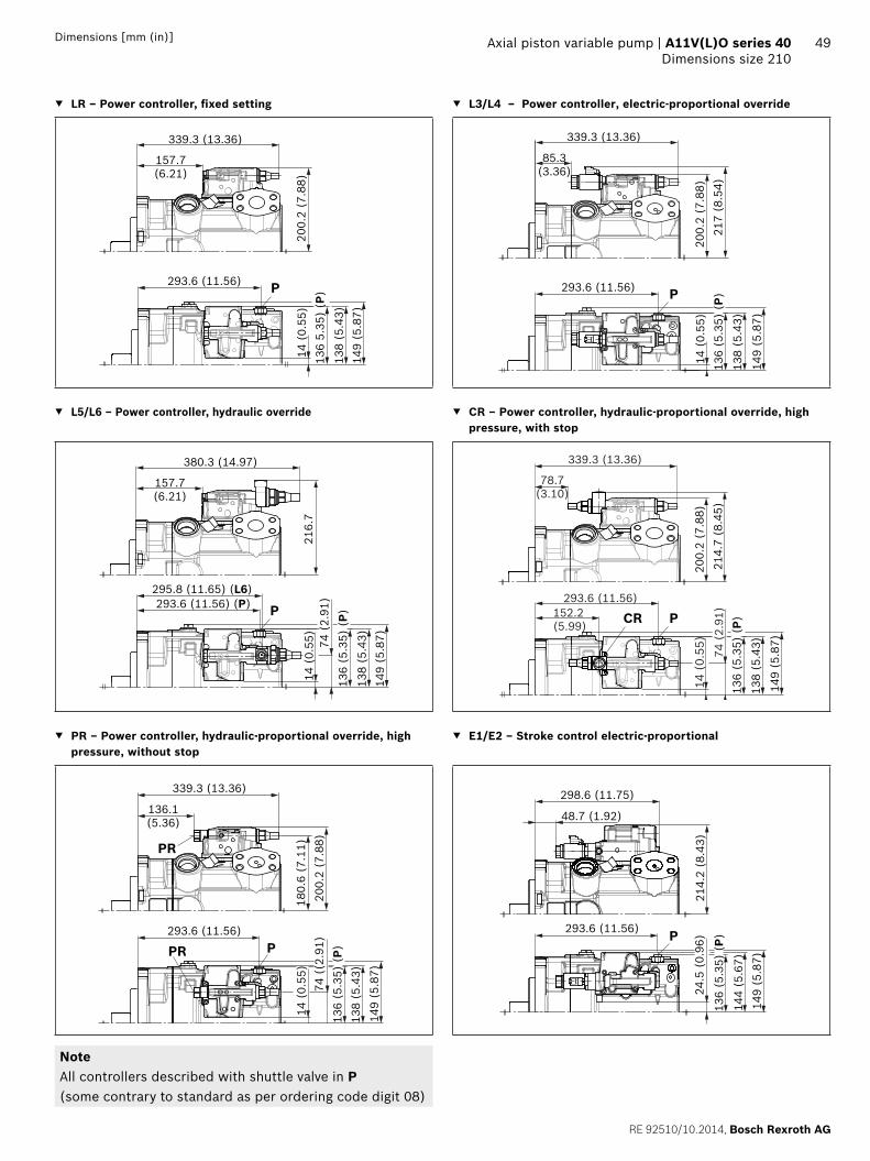
RE 92510/10.2014, Bosch Rexroth AG
Axial piston variable pump | A11V(L)O series 40 Dimensions size 210
49Dimensions [mm (in)]
LR – Power controller, fi xed setting L3/L4 – Power controller, electric-proportional override
14 (
0.55
)20
0.2
(7.8
8)13
6 5.
35)
(P)
293.6 (11.56)
138
(5.4
3)
P
157.7(6.21)
339.3 (13.36)
149
(5.8
7)
14 (
0.55
)20
0.2
(7.8
8)13
6 (5
.35)
(P)
293.6 (11.56)
138
(5.4
3)
217
(8.5
4)
85.3(3.36)
339.3 (13.36)
P
149
(5.8
7)
L5/L6 – Power controller, hydraulic override CR – Power controller, hydraulic-proportional override, high pressure, with stop
14 (
0.55
)21
6.7
136
(5.3
5) (
P)74
(2.
91)293.6 (11.56) (P)
295.8 (11.65) (L6)
138
(5.4
3)
P
157.7(6.21)
380.3 (14.97)
149
(5.8
7)
14 (
0.55
)20
0.2
(7.8
8)
136
(5.3
5) (
P)
152.2(5.99)
138
(5.4
3)
74 (
2.91
)21
4.7
(8.4
5)
293.6 (11.56)
PCR
78.7(3.10)
339.3 (13.36)
149
(5.8
7)
PR – Power controller, hydraulic-proportional override, high pressure, without stop
E1/E2 – Stroke control electric-proportional
136.1(5.36)
339.3 (13.36)
74 (
(2.9
1)13
6 (5
.35)
(P)
138
(5.4
3)
293.6 (11.56)
14 (
0.55
)18
0.6
(7.1
1)20
0.2
(7.8
8)
PPR
PR
149
(5.8
7)
24.5
(0.
96)
136
(5.3
5) (
P)14
4 (5
.67)
214.
2 (8
.43)
293.6 (11.56)
48.7 (1.92)
298.6 (11.75)
P
149
(5.8
7)
NoteAll controllers described with shuttle valve in P (some contrary to standard as per ordering code digit 08)

Bosch Rexroth AG, RE 92510/10.2014
50 A11V(L)O series 40 | Axial piston variable pumpDimensions size 210
Dimensions [mm (in)]
H3/H4 – Stroke control, hydraulic-proportional, pilot pressure DR – Pressure controller, fi xed setting
49 (
1.93
) (H
3)
120.2(4.73)
295.6 (11.64)
73.2(2.88)
136
(5.3
5) (
P)14
4 (5
.76)
293.6 (11.56)24
.5 (
0.96
)15
1.2
(5.9
5)21
4.2
(8.4
3)P
H3, H4
149
(5.8
7)
157.7(6.21)
319.6 (12.58)
200.
2 (7
.88)
136
(5.3
3) (
P)
293.6 (11.56)
138
(5.4
3)
14 (
0.55
)
149
(5.8
7)
P
LRDRS0 – Power controller with pressure controller and load sensing, fi xed setting
DG – Pressure controller, hydraulic, remote controlled
200.
2 (7
.88)
136
(5.3
5) (
P)
293.6 (11.56)230.7 (9.08)
116
(4.5
7)
138
(5.4
3)
14 (
0.55
)
PX
157.7(6.21)
339.3 (13.36)
149
(5.8
7)
7.25
(18
4.2)
7.88
(20
0.2)
6.21(157.7)
12.66 (321.7)
11.56 (293.6)9.08 (230.7)
0.55
(14
)4.
57 (
116)
(X)
5.35
(13
6)(P
)5.
43 (
138)
5.87
(14
9)
X
X P
NoteAll controllers described with shuttle valve in P (some contrary to standard as per ordering code digit 08)

RE 92510/10.2014, Bosch Rexroth AG
Axial piston variable pump | A11V(L)O series 40 Dimensions size 280
51Dimensions [mm (in)]
Dimensions size 280
LRDRS0 – Power controller with pressure controller, load sensing and with electric swivel angle sensorWithout charge pump, clockwise rotation
T3
A
6.5
(0.2
6)1)
195.8 (7.71)1)4.
2 (0
.17)
1)
140 (5.51)(T3)
156.
4 (6
.16)
208.
3 (8
.20)
34 (1.34)
324 (12.76)
387 (15.24)
10 (0.39)
165 (
6.50)
45°
36.5
(1.44
)
79.4(3.13)
69.9
(2.
75)
120.7(4.75)
224.
5 (8
.84)
224.5 (8.84)
262.
5 (1
0.33
)
262.5 (10.33)
90(3.54)
38 (1.50)
20.6
(0.81
)
50 (1.97)5 (0.20)
144(5.76)
121
(4.7
6)
162 (6.38)
45°
15
(0.59
)
135
(5.3
1)
6.49
8
ø165
.1-0
.05
6.50
0(D
IA
)
140(5.51)
332 (13.07) (T3)
261.4 (10.29)
317 (12.48)
150
(5.9
0)18
7.6
(7.3
9)
0.610.6315.9-0.5 ( )
329 (12.95) (P)
138
(5.4
3)
192.
4 (7
.57)
W
X
T2 S
A
T1 A
T1
MA
M
P
X
X
MA
S
S
Z
T2
T3
PA
122 (4.80)
43 (1.69)
Detail X
Detail W
Detail Z
Version “M”M12 x 1.75; 22 (0.87) deepVersion “A”1/2-13UNC-2B, 22 (0.87) deepThread for eye bolt
Flange E4SAE J744
1) Center of gravity

Bosch Rexroth AG, RE 92510/10.2014
52 A11V(L)O series 40 | Axial piston variable pumpDimensions size 280
Dimensions [mm (in)]
LRDRS0 – Power controller with pressure controller, load sensing and with electric swivel angle sensorWith charge pump, clockwise rotation
Z
T2
A
T3
156.
4 (6
.16)
208.
3 (8
.20)
34 (1.34)
359 (14.13)
10 (0.39)
165 (
6.50)
45°
36.5
(1.44
)
79.4(3.13)
77.8
(3.0
6)
130.2(5.12)
224.
5 (8
.84)
224.5 (8.84)
262.
5 (1
0.33
)
262.5 (10.33)
100(3.94)
38 (1.50)
20.6
(0.81
)
18 (0.71)5 (0.20)
144 (5.67)
121
(4.7
6)
162 (6.38)
45°
15
(0.59
)
144
(5.6
7)
ø165
.1-0
.05
6.50
06.
498
(DIA
)
140(5.51)
261.4 (10.29)
317 (12.48)
150
(5.9
0)18
7.6
(7.3
8)
0.610.63
15.9-0.5 ( )
425 (16.73)443 (17.44)
122 (4.80)
332 (13.07) (T3)329 (12.95) (P)
138
(5.4
3)
W
X
T2 S
A
T1 A
T1
MA
M
P
X
X
MA
S
S
3.8
(0.1
5)1)
235 (9.25)1)
3.2
(0.1
3)1)
43 (1.69)
192.
4 (7
.57)
140 (5.51)(T3)
Detail X
Detail W
Detail Z
Version “M”M12 x 1.75; 22 (0.87) deepVersion “A”1/2-13UNC-2B, 22 (0.87) deepThread for eye bolt
Flange E4SAE J744
1) Center of gravity

RE 92510/10.2014, Bosch Rexroth AG
Axial piston variable pump | A11V(L)O series 40 Dimensions size 280
53Dimensions [mm (in)]
Splined shaft SAE J744 Splined shaft DIN 5480
T3 ‒ 2 1/4 in 17T 8/16DP1) A4 ‒ W60x2x28x9g
87.9 (3.46)
42(1.65)
66 (2.60)
3/4-
10U
NC
-2B
2) 4
)
ø70
(2.7
6)
80 (3.15)
15(0.59)
ø140
(D
IA 5
.51)
M20
x 2
.53)
4)
65.9(2.59)
ø70
(2.7
6)
15(0.59)
42(1.65)
58 (2.28)
47(1.85)
ø140
(5.
51)
1) Involute spline according to ANSI B92.1a, 30° pressure angle, fl at root, side fi t, tolerance class 5
2) Thread according to ASME B1.13) Center bore according to DIN 332 (thread according to DIN 13)4) Observe the instructions in the operating instructions concerning
the maximum tightening torques.5) Depending on the application, momentary pressure spikes can occur.
Keep this in mind when selecting measuring equipment and fi ttings.
6) Metric fastening thread is a deviation from standard7) The spot face can be deeper than as specifi ed in the standard.8) Depending on installation position, T1, T2 or T3 must be connected
(see also installation instructions on pages 63 and 64).9) O = Must be connected (plugged on delivery)
X = Plugged (in normal operation)

Bosch Rexroth AG, RE 92510/10.2014
54 A11V(L)O series 40 | Axial piston variable pumpDimensions size 280
Dimensions [mm (in)]
Ports - version “M” metric Standard Size4) pmax abs
[bar (psi)]5)State9)
A Working line portFastening thread
SAE J5186)
DIN 131 1/2 inM16 x 2; 24 (0.94) deep
420 (6100) O
S Suction port (without charge pump)Fastening thread
SAE J5186)
DIN 133 1/2 inM16 x 2; 24 (0.94) deep
30 (435) O
S Suction port (with charge pump)Fastening thread
SAE J5186)
DIN 134 inM16 x 2; 24 (0.94) deep
2 (30) O
T1 Drain port ISO 61497) M42 x 2; 19.5 (0.77) deep 10 (145) O8)
T2 Drain port ISO 61497) M42 x 2; 19.5 (0.77) deep 10 (145) X8)
T3 Drain port ISO 61497) M42 x 2; 19.5 (0.77) deep 10 (145) X8)
CR Pilot signal (CR only) ISO 6149 M14 x 1.5; 11.5 (0.45) deep 420 (6100) O
PR Pilot signal (PR only) ISO 6149 M14 x 1.5; 11.5 (0.45) deep 420 (6100) O
H3, H4 Pilot signal (H3 and H4 only) ISO 6149 M14 x 1.5; 11.5 (0.45) deep 100 (1450) O
L5, L6 Override power regulator (only with L5 and L6) ISO 6149 M14 x 1.5; 11.5 (0.45) deep 100 (1450) O
X Pilot signal (S0 and DG only) ISO 61497) M14 x 1.5; 11.5 (0.45) deep 420 (6100) O
M Measuring, control pressure ISO 61497) M14 x 1.5; 12 (0.47) deep 420 (6100) X
MA Measuring, pressure A ISO 61497) M14 x 1.5; 12 (0.47) deep 420 (6100) X
P External control pressure (ordering code digit 8 ver-sion B or C = with external control pressure supply)
ISO 61497) M14 x 1.5; 11.5 (0.45) deep 50 (725) O
Port P without function(Ordering code digit 8 version A = without external control pressure supply)
ISO 61497) M18 x 1.5; 14.5 0.57) deep 420 (6100) X
Ports - version “A” SAE Standard Size4) pmax abs
[bar (psi)]5)State9)
A Working line portFastening thread
SAE J518ASME B1.1
1 1/2 in5/8-11UNC-2B; 35 (1.38) deep
420 (6100) O
S Suction port (without charge pump)Fastening thread
SAE J518ASME B1.1
3 1/2 in5/8-11UNC-2B; 35 (1.38) deep
30 (435) O
S Suction port (with charge pump)Fastening thread
SAE J518ASME B1.1
3 1/2 in5/8-11UNC-2B; 35 (1.38) deep
2 (30) O
T1 Drain port ISO 119267) 1 5/8UN-2B; 20 (0.79) deep 10 (145) O8)
T2 Drain port ISO 119267) 1 5/8UN-2B; 20 (0.79) deep 10 (145) X8)
T3 Drain port ISO 119267) 1 5/8UN-2B; 20 (0.79) deep 10 (145) X8)
CR Pilot signal (CR only) ISO 11926 9/16-18UNF-2B; 13 (0.51) deep 420 (6100) O
PR Pilot signal (PR only) ISO 11926 9/16-18UNF-2B; 13 (0.51) deep 420 (6100) O
H3, H4 Pilot signal (H3 and H4 only) ISO 11926 9/16-18UNF-2B; 13 (0.51) deep 100 (1450) O
L5, L6 Override power regulator (only with L5 and L6) ISO 11926 9/16-18UNF-2B; 13 (0.51) deep 100 (1450) O
X Pilot signal (S0 and DG only) ISO 119267) 9/16-18UNF-2B; 13 (0.51) deep 420 (6100) O
M Measuring, control pressure ISO 119267) 9/16-18UNF-2B; 13 (0.51) deep 420 (6100) X
MA Measuring, pressure A ISO 119267) 9/16-18UNF-2B; 13 (0.51) deep 420 (6100) X
P External control pressure(Ordering code digit 8 version B or C = with exter-nal control pressure supply)
ISO 119267) 9/16-18UNF-2B; 13 (0.51) deep 50 (725) O
Port P without function(Ordering code digit 8 version A = without external control pressure supply)
ISO 119267) 3/4-16UNF-2B; 12.6 (0.50) deep 420 (6100) X

RE 92510/10.2014, Bosch Rexroth AG
Axial piston variable pump | A11V(L)O series 40 Dimensions size 280
55Dimensions [mm (in)]
LR – Power controller, fi xed setting L3/L4 – Power controller, electric-proportional override
144
(5.6
7)
208.
3 (8
.20)
188.4(7.42)
145.
5 (5
.73)
(P)329 (12.95)
20 (
0.79
)
370 (14.57)
P
158
(6.2
2)
144
(5.6
7)20
8.3
(8.2
0)
116(4.57)
145.
5 (5
.73)
(P)329 (12.95)
20 (
0.79
)
370 (14.57)
225.
1 (8
.86)
P
L5/L6 – Power controller, hydraulic override CR – Power controller, hydraulic-proportional override, high pressure, with stop
144
(5.6
7)80
(3.
15)
224.
8 (8
.85)
188.4(7.42)
145.
5 (5
.73)
(P)
329 (12.95) (P)326.5 (12.85) (L6)
20 (
0.79
)
411 (16.18)
PL6
L6
158
(6.2
2)
PCR
80 (
3.15
)
144
(5.6
7)
158
(6.2
2)
222.
8 (8
.77)
109.4(4.31)
145.
5 (5
.73)
(P)
329 (12.95)
20 (
0.79
)
370 (14.57)
182.9 (7.20)
PR – Power controller, hydraulic-proportional override, high pressure, without stop
E1/E2 – Stroke control electric-proportional
166.8(6.57)
370 (14.57)
329 (12.95)
20 (
0.79
)
145.
5 (5
.73)
(P)
80 (
3.15
)
PPR
PR
208.
3 (8
.20)
188.
7 (7
.43)
158
(6.2
2)
222.
3 (8
.75)
329.4 (12.97)
79.4(3.13)
150
(5.9
1)
30.5
(1.
20)
145.
5 (5
.73)
(P)P329 (12.95)
NoteAll controllers described with shuttle valve in P (some contrary to standard as per ordering code digit 08)
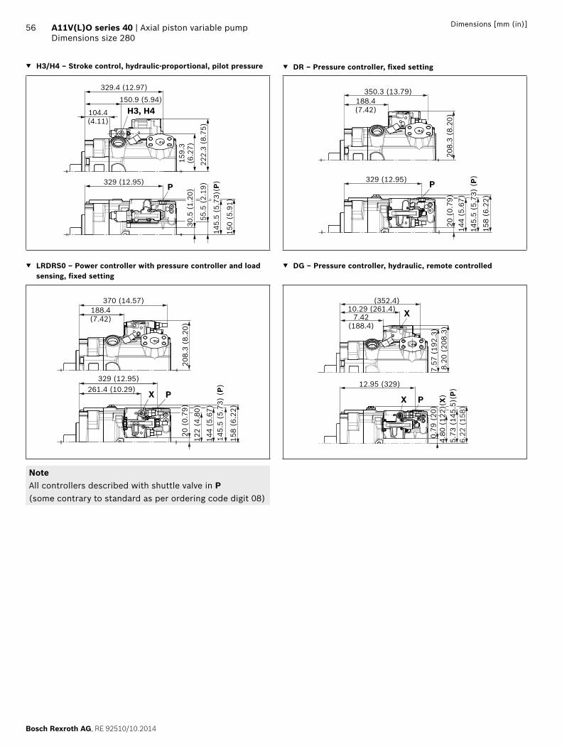
Bosch Rexroth AG, RE 92510/10.2014
56 A11V(L)O series 40 | Axial piston variable pumpDimensions size 280
Dimensions [mm (in)]
H3/H4 – Stroke control, hydraulic-proportional, pilot pressure DR – Pressure controller, fi xed setting
222.
3 (8
.75)
150.9 (5.94)
104.4(4.11)
329.4 (12.97)
159.
3(6
.27)
H3, H4
P
150
(5.9
1)
145.
5 (5
.73)
(P)329 (12.95)
30.5
(1.
20)
55.5
(2.
19)
208.
3 (8
.20)
188.4(7.42)
145.
5 (5
.73)
(P)329 (12.95)
20 (
0.79
)
350.3 (13.79)
144
(5.6
7)
158
(6.2
2)
P
LRDRS0 – Power controller with pressure controller and load sensing, fi xed setting
DG – Pressure controller, hydraulic, remote controlled
208.
3 (8
.20)
188.4(7.42)
145.
5 (5
.73)
(P)
329 (12.95)261.4 (10.29)
20 (
0.79
)
370 (14.57)
144
(5.6
7)
122
(4.8
0)
PX
158
(6.2
2)
7.57
(19
2.3)
8.20
(20
8.3)
7.42(188.4)
10.29 (261.4)(352.4)
0.79
(20
)4.
80 (
122)
(X)
5.73
(14
5.5)
(P)12.95 (329)
X
X P
6.22
(15
8)NoteAll controllers described with shuttle valve in P(some contrary to standard as per ordering code digit 08)

RE 92510/10.2014, Bosch Rexroth AG
Axial piston variable pump | A11V(L)O series 40 Through drives dimensions
57Dimensions [mm (in)]
Through drives dimensions
Flange SAE J744 Coupling for splined shaft1) Availability over sizes Code
Diameter Attachment2) Designation Diameter Designation 110 145 175 210 280
82-2 (A) A3 5/8 in 9T 16/32DP S2 A3S2
3/4 in 11T 16/32DP S3 A3S3
101-2 (B) B3 7/8 in 13T 16/32DP S4 B3S4
1 in 15T 16/32DP S5 B3S5
B5 7/8 in 13T 16/32DP S4 B5S4
1 in 15T 16/32DP S5 B5S5
82-2 (A)
M2
7(0.27)
106.4(4.19)
ø82.
55+0
.02
3.25
13.
252
(DIA
)
+0.0
5
A3
Version “M” M10; 15 (0.59) deep3)
Version “A” 3/8-16UNC-2B; 15 (0.59) deep3)
O-ring5)
M1 (to mounting fl ange)
A3S2 NG M1 M2
without charge pump 110 301 (11.85) 34 (1.39)
145 326 (12.83) 40 (1.57)
175 340.5 (13.41) 33.8 (1.33)
210 357.8 (14.09) 33.8 (1.33)
280 400 (15.75) 33.8 (1.33)
with charge pump 145 374.7 (14.75) 40 (1.57)
175 389.5 (15.33) 33.8 (1.33)
210 406.8 (16.02) 33.8 (1.33)
280 438 (17.24) 33.8 (1.33)
A3S3 NG M1 M2
without charge pump 175 340.5 (13.41) 40 (1.57)
210 357.8 (14.09) 40 (1.57)
280 400 (15.75) 40 (1.57)
with charge pump 175 389.5 (15.33) 40 (1.57)
210 406.8 (16.02) 40 (1.57)
280 438 (17.24) 40 (1.57)
101-2 (B)
M1 (to mounting fl ange)
Version “M” M12; 18 (0.71) deep3)
Version “A” 1/2-13UNC-2B; 18 (0.71) deep3)
O-ring5)
M2
11(0.43)
B3B5
146 (5.75)
146
(5.7
5)B
3B
5
ø101
.6+0
.02
4.00
14.
002
(DIA
)
+0.0
5
B3S4, B5S4 NG M1 M2
without charge pump 110 312 (12.28) 43 (1.69)
145 337 (13.27) 43 (1.69)
175 354.5 (13.96) 43 (1.69)
210 371.8 (14.64) 43 (1.69)
280 414 (16.30) 43 (1.69)
with charge pump 145 385.7 (15.19) 43 (1.69)
175 403.5 (15.89) 43 (1.69)
210 420.8 (16.57) 43 (1.69)
280 452 (17.80) 43 (1.69)
B3S5, B5S5 NG M1 M2
without charge pump 110 312 (12.28) 48 (1.89)
145 337 (13.27) 48 (1.89)
175 354.5 (13.96) 48 (1.89)
210 371.8 (14.64) 48 (1.89)
280 414 (16.30) 48 (1.89)
with charge pump 145 385.7 (15.18) 48 (1.89)
175 403.5 (15.89) 48 (1.89)
210 420.8 (16.57) 48 (1.89)
280 452 (17.80) 48 (1.89)
1) According to ANSI B92.1a, 30° pressure angle, fl at root, side fi t, tolerance class 5
2) Mounting drillings pattern viewed from through drive with control at top
3) Thread according to DIN 13, observe the general instructions on page 65 for the maximum tightening torques.
4) Thread according to ASME B1.1, observe the general instructions on page 65 for the maximum tightening torques.
5) O-ring included in the scope of supply
= Available = On request
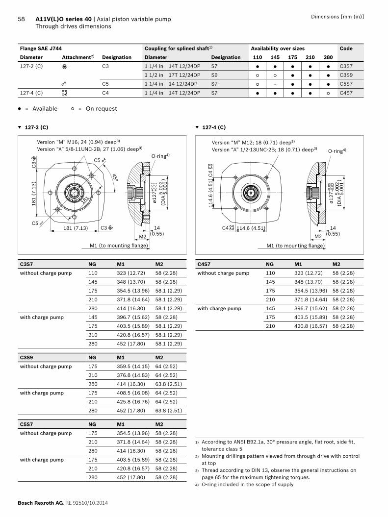
Bosch Rexroth AG, RE 92510/10.2014
58 A11V(L)O series 40 | Axial piston variable pumpThrough drives dimensions
Dimensions [mm (in)]
Flange SAE J744 Coupling for splined shaft1) Availability over sizes Code
Diameter Attachment2) Designation Diameter Designation 110 145 175 210 280
127-2 (C) C3 1 1/4 in 14T 12/24DP S7 C3S7
1 1/2 in 17T 12/24DP S9 C3S9
C5 1 1/4 in 14 12/24DP S7 – C5S7
127-4 (C) C4 1 1/4 in 14T 12/24DP S7 C4S7
= Available = On request
127-2 (C)
Version “M” M16; 24 (0.94) deep3)
Version “A” 5/8-11UNC-2B; 27 (1.06) deep3)
O-ring4)
M1 (to mounting fl ange)
14(0.55)
181 (7.13)
181
(7.1
3)
M2
C3
C5
C5
ø127
+0.0
2
5.00
15.
002
(DIA
)
+0.0
5
C3
45°
181
C3S7 NG M1 M2
without charge pump 110 323 (12.72) 58 (2.28)
145 348 (13.70) 58 (2.28)
175 354.5 (13.96) 58.1 (2.29)
210 371.8 (14.64) 58.1 (2.29)
280 414 (16.30) 58.1 (2.29)
with charge pump 145 396.7 (15.62) 58 (2.28)
175 403.5 (15.89) 58.1 (2.29)
210 420.8 (16.57) 58.1 (2.29)
280 452 (17.80) 58.1 (2.29)
C3S9 NG M1 M2
without charge pump 175 359.5 (14.15) 64 (2.52)
210 376.8 (14.83) 64 (2.52)
280 414 (16.30) 63.8 (2.51)
with charge pump 175 408.5 (16.08) 64 (2.52)
210 425.8 (16.76) 64 (2.52)
280 452 (17.80) 63.8 (2.51)
C5S7 NG M1 M2
without charge pump 175 354.5 (13.96) 58 (2.28)
210 371.8 (14.64) 58 (2.28)
280 414 (16.30) 58 (2.28)
with charge pump 175 403.5 (15.89) 58 (2.28)
210 420.8 (16.57) 58 (2.28)
280 452 (17.80) 58 (2.28)
127-4 (C)
Version “M” M12; 18 (0.71) deep3)
Version “A” 1/2-13UNC-2B; 18 (0.71) deep3) O-ring4)
M1 (to mounting fl ange)
14(0.55)M2
C4 114.6 (4.51)
114.
6 (4
.51)
C4
ø127
+0.0
2
5.00
15.
002
(DIA
)
+0.0
5
C4S7 NG M1 M2
without charge pump 110 323 (12.72) 58 (2.28)
145 348 (13.70) 58 (2.28)
175 354.5 (13.96) 58 (2.28)
210 371.8 (14.64) 58 (2.28)
with charge pump 145 396.7 (15.62) 58 (2.28)
175 403.5 (15.89) 58 (2.28)
210 420.8 (16.57) 58 (2.28)
1) According to ANSI B92.1a, 30° pressure angle, fl at root, side fi t, tolerance class 5
2) Mounting drillings pattern viewed from through drive with control at top
3) Thread according to DIN 13, observe the general instructions on page 65 for the maximum tightening torques.
4) O-ring included in the scope of supply

RE 92510/10.2014, Bosch Rexroth AG
Axial piston variable pump | A11V(L)O series 40 Through drives dimensions
59Dimensions [mm (in)]
Flange SAE J744 Coupling for splined shaft1) Availability over sizes Code
Diameter Attachment2) Designation Diameter Designation 110 145 175 210 280
152-4 (D) D4 1 3/4 in 13T 8/16DP T1 D4T1
165-4 (E) E4 1 3/4 in 13T 8/16DP T1 – – E4T1
2 in 15T 8/16DP T2 – – E4T2
2 1/4 in 17T 8/16 DP T3 – – – – E4T3
W60x2x28x9g5) A4 – – – – E4A4
= Available = On request
152-4 (D)
Version “M” M20; 30 (1.18) deep3)
Version “A” 3/4-10UNC-2B; 45 (1.77) deep3)O-ring4)
M1 (to mounting fl ange)
14(0.55)M2
D4 161.6 (6.36)
161.
6 (6
.36)
D4
ø152
.4+0
.02
5.99
96.
003
(DIA
)
+0.0
7
D4T1 NG M1 M2
without charge pump 110 336 (13.23) 77 (3.03)
145 361 (14.21) 76.8 (3.02)
175 372.5 (14.67) 76.8 (3.02)
210 389.8 (15.35) 76.8 (3.02)
280 432 (17.01) 77 (3.03)
with charge pump 145 409.7 (16.13) 76.8 (3.02)
175 421.5 (16.59) 76.8 (3.02)
210 438.8 (17.28) 76.8 (3.02)
280 470 (18.50) 77 (3.03)
165-4 (E)
17(0.67)M2
E4 224.5 (8.84)
224.
5 (8
.84)
E4
ø165
.1+0
.02
6.50
16.
503
(DIA
)
+0.0
7
M1 (to mounting fl ange)
Version “M” M20; 36 (1.42) deep3)
Version “A” 3/4-10UNC-2B; 45 (1.77) deep3)O-ring4)
E4T1 NG M1 M2
without charge pump 175 355 (13.98) 77 (3.03)
210 389.8 (15.35) 77 (3.03)
280 432 (17.00) 77 (3.03)
with charge pump 175 421.5 (16.59) 77 (3.03)
210 438.8 (17.27) 77 (3.03)
280 470 (18.50) 77 (3.03)
E4T2 NG M1 M2
without charge pump 175 385.5 (15.18) 90 (3.54)
210 402.8 (15.86) 90 (3.54)
280 445 (17.52) 90 (3.54)
with charge pump 175 434.5 (17.11) 90 (3.54)
210 451.8 (17.79) 90 (3.54)
280 483 (19.02) 90 (3.54)
E4T3 NG M1 M2
without charge pump 280 445 (17.52) 90 (3.54)
with charge pump 280 483 (19.02) 90 (3.54)
E4A4 NG M1 M2
without charge pump 280 423 (16.65) 68 (2.68)
with charge pump 280 461 (18.15) 68 (2.68)
1) According to ANSI B92.1a, 30° pressure angle, fl at root, side fi t, tolerance class 5
2) Mounting drillings pattern viewed from through drive with control at top
3) Thread according to DIN 13, observe the general instructions on page 65 for the maximum tightening torques.
4) O-ring included in the scope of supply5) Hub N60x2x28x8H according to DIN 5480

Bosch Rexroth AG, RE 92510/10.2014
60 A11V(L)O series 40 | Axial piston variable pumpOverview of attachment options
Dimensions [mm (in)]
Overview of attachment options
Through drive1) Attachment of 2nd pump
Flange Coupling for splined shaft
Short code
A11VO/40NG (shaft)
A10VO/31 NG (shaft)
A10VO/32 NG (shaft)
A4VG/32 NG (shaft)
A4VG/40 NG (shaft)
A10VO/52 and 53 NG (shaft)
External gear-pump
82-2 (A) 5/8 in A3S2 – 18 (U) – – – 10, 18 (U) Series F2)
3/4 in A3S3 18 (S, R) 10 (S), 18 (S, R)
101-2 (B) 7/8 in B_S4 – 28 (S, R); 45 (U, W)
– – – 28 (R, S);
45 (U, W)
Series N2)
1 in B_S5 – 45 (R, S) – 28 (S) – 45 (R, S);
60, 63 (U, W)
PGH4
127-2 (C) 1 1/4 in C_S7 – 71 (R, S); 100 (U, W)
71 (R) (S) 40, 56, 71 (S)
45, 65 (S7) 85, 100 (U, W) –
1 1/2 in C3S9 – 100 (S) 100 (S) – 45, 65 (S9) 85, 100 (S) PGH5
1 1/4 in C5S7 71 (S, R)
100 (U, W)
71 (S, R)
100 (U, W)
85, 100 (U, W)
127-4 (C) 1 1/4 in C4S7 – – 71 (R) (S) – 65 (S7) 60, 63 (R, S)
85 (U, W)
–
1 3/8 in C4V8 – – – – 85, 110 (V8) – –
152-4 (D) 1 1/4 in D4S7 – – 100 (U, W) 90 (U) – – –
1 3/8 in D4V8 – – – – 85, 110 (V8) – –
1 3/4 in D4T1 110, 145 (T1)
140 (S) 140 (S) 90, 125 (S) 145 (T1) – –
165-4 (E) 1 3/4 in E4T1 – – – 180, 250 (S) 145, 175 (T1)
– –
2 in E4T2 175, 210 (T2)
– – – 145 (T2) – –
2 1/4 in E4T3 280 (T3) – – 180, 250 (T) 175 (T3) – –
W60 E4A4 280 (A4) – – – – – –
1) Additional through drives are available on request2) Bosch Rexroth recommends special versions of the external gear
pumps. Please contact us.

RE 92510/10.2014, Bosch Rexroth AG
Axial piston variable pump | A11V(L)O series 40 Combination pumps A11V(L)O + A11V(L)O
61Dimensions [mm (in)]
Combination pumps A11V(L)O + A11V(L)O
Total length A
A11VO(1st pump)
A11VO (2nd pump) A11VLO (2nd pump)
NG110 NG145 NG175 NG210 NG280 NG280 NG145 NG175 NG210 NG280 NG280
D4T1 D4T1 E4T2 E4T2 E4A4 E4T3 D4T1 E4T2 E4T2 E4A4 E4T3
NG110 621(24.45)
– – – – – – – – – –
NG145 646(2543)
671(2642)
– – – – 736.2(28.98)
– – – –
NG175 657.5(25.89)
682.5(26.87)
713(28.07)
– – – 747.7(29.44)
780(30.71)
– – –
NG210 674.8(26.57)
699.8(27.55)
730.3(28.75)
747.6(29.43)
– – 765(30.12)
797.3(31.00)
814.6(32.07)
– –
NG280 717(28.23)
742(29.21)
772.5(30.41)
789.8(31.09)
810(31.90)
832(32.76)
807.2(31.78)
839.5(33.05)
856.8(33.73)
866(34.09)
888(34.96)
A11VLO(1st pump)
A11VO (2nd pump) A11VLO (2nd pump)
NG110 NG145 NG175 NG210 NG280 NG280 NG145 NG175 NG210 NG280 NG280
D4T1 D4T1 E4T2 E4T2 E4A4 E4T3 D4T1 E4T2 E4T2 E4A4 E4T3
NG 145 694.7(27.35)
719.7(28.33)
– – – – 784.9(30.90)
– – – –
NG175 706.5(27.81)
731.5(28.80)
762(30.00)
– – – 796.7(31.37)
829(32.64)
– – –
NG210 723.8(28.50)
748.8(29.48)
779.3(30.68)
796.6(31.36)
– – 814(32.05)
846.3(33.32)
863.6(34.00)
– –
NG280 755(29.72)
780(30.71)
810.5(31.91)
827.8(32.59)
848(33.39)
870(34.25)
845.2(33.28)
877.5(34.55)
894.8(35.23)
904(35.59)
926(36.46)
By using combination pumps, it is possible to have inde-pendent circuits without the need for splitter gearboxes. When ordering combination pumps, the type designations of the 1st and 2nd pump must be linked by a “+”.Order example:A11VO280LRDRA00/40M(A)RVE4A41SE4A40-0+A11VO280LRDRA00/40M(A)RVE4A41SU0000-0A tandem pump consisting of two equal sizes is permissible without additional supports assuming that the dynamic mass acceleration does not exceed maximum 10 g (= 98.1 m/s2). For combination pumps consisting of more than two pumps, the mounting fl ange must be rated for the permissible mass torque.
A
A11VO(1st pump)
A11VO(2nd pump)
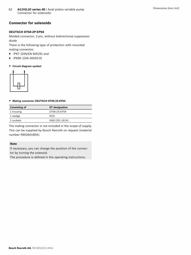
Bosch Rexroth AG, RE 92510/10.2014
62 A11V(L)O series 40 | Axial piston variable pumpConnector for solenoids
Dimensions [mm (in)]
Connector for solenoids
DEUTSCH DT04-2P-EP04Molded connector, 2-pin, without bidirectional suppressor diode There is the following type of protection with mounted mating connector:
IP67 (DIN/EN 60529) and IP69K (DIN 40050-9)
Circuit diagram symbol
Mating connector DEUTSCH DT06-2S-EP04
Consisting of DT designation
1 housing DT06-2S-EP04
1 wedge W2S
2 sockets 0462-201-16141
The mating connector is not included in the scope of supply. This can be supplied by Bosch Rexroth on request (material number R902601804).
NoteIf necessary, you can change the position of the connec-tor by turning the solenoid.The procedure is defi ned in the operating instructions.

RE 92510/10.2014, Bosch Rexroth AG
Axial piston variable pump | A11V(L)O series 40 Installation instructions
63
Installation instructions
GeneralThe axial piston unit must be fi lled with hydraulic fl uid and air bled during commissioning and operation. This must also be observed following a longer standstill as the axial piston unit empty via the hydraulic lines.Particularly in the installation position “drive shaft upwards”, fi lling and air bleeding must be carried out com-pletely as there is, for example, a danger of dry running.The case drain fl uid in the pump housing must be directed to the reservoir via the highest available drain port (T1, T2, T3).For combinations of multiple units, the case drain fl uid must be drained off at each pump. If a shared drain line is used for this purpose, make sure that the case pressure in each pump is not exceeded. In the event of pressure diff e-rences at the drain ports of the units, the shared drain line must be changed so that the minimum permissible case pressure of all connected units is not exceeded in any situa-tion. If this is not possible, separate drain lines must be laid if necessary.To achieve favorable noise values, decouple all connecting lines using elastic elements and avoid above-reservoir installation. In all operating conditions, the suction line and drain line must fl ow into the reservoir below the minimum fl uid level. The permissible suction height hS results from the overall loss of pressure. However, it must not be higher than hS max = 800 mm. The minimum suction pressure at port S must also not fall below 0.8 bar absolute (without charge pump) or 0.7 bar absolute (with charge pump) during operation and during a cold start.When designing the reservoir, ensure adequate distance between the suction line and the case drain line. This prevents the heated, return fl ow from being drawn directly back into the suction line.
NoteIn certain installation positions, an infl uence on the con-trol characteristics can be expected. Gravity, dead weight and case pressure can cause minor shifts in control cha-racteristic curves and changes in response time.
Installation position See examples 1 to 9 below.Further installation positions are available upon request.Recommended installation position: 1 and 2
Below-tank installation (standard)Below-tank installation is when the axial piston unit is installed outside of the tank below the minimum fl uid level.
Installation position Air bleeding
Filling
1 SBht min
hmin
T1
T3
T2 S
T1 S + T1
2 SBht min
hmin
T1
T3
T2 S
T2 S + T2
3SB
ht min
hmin
T1
T3
T2
S
T2 S + T2
Key
L Filling / air bleeding
S Suction port
T Drain port
SB Baffl e (baffl e plate)
ht min Minimum necessary immersion depth (200 mm)
hmin Minimum required spacing to reservoir base (100 mm)
hES min Minimum necessary height needed to protect the axial piston unit from draining (25 mm).
hS max Maximum permissible suction height (800 mm)
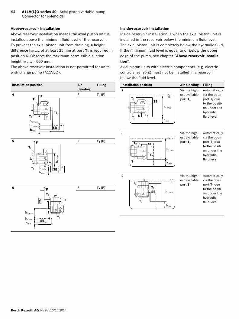
Bosch Rexroth AG, RE 92510/10.2014
64 A11V(L)O series 40 | Axial piston variable pumpConnector for solenoids
Above-reservoir installationAbove-reservoir installation means the axial piston unit is installed above the minimum fl uid level of the reservoir. To prevent the axial piston unit from draining, a height diff erence hES min of at least 25 mm at port T2 is required in position 6. Observe the maximum permissible suction height hS max = 800 mm.The above-reservoir installation is not permitted for units with charge pump (A11VLO).
Installation position Air bleeding
Filling
4
SBht min
F
hmin
hS max
T1
T2
T3
S
F T1 (F)
5
SB
F
ht minhmin
h S m
ax
T1
T2
T3
S
F T2 (F)
6
ht min
hmin
hS max
SB
F
T1
T2
T3
S
F T2 (F)
Inside-reservoir installationInside-reservoir installation is when the axial piston unit is installed in the reservoir below the minimum fl uid level. The axial piston unit is completely below the hydraulic fl uid.If the minimum fl uid level is equal to or below the upper edge of the pump, see chapter “Above-reservoir installa-tion”.Axial piston units with electric components (e.g. electric controls, sensors) must not be installed in a reservoir below the fl uid level.
Installation position Air bleeding Filling
7
Shmin
ht min
T1
T2T3
SB
Via the high-est available port T1
Automatically via the open port T1 due to the positi-on under the hydraulic fl uid level
8
S
hmin
ht min
T2
T1
T3
SB
Via the high-est available port T2
Automatically via the open port T2 due to the positi-on under the hydraulic fl uid level
9
T2
ht min
T1
T3
hmin
SB
Via the high-est available port T2
Automatically via the open port T2 due to the positi-on under the hydraulic fl uid level
RE 92510/10.2014, Bosch Rexroth AG
Axial piston variable pump | A11V(L)O series 40 Project planning notes
65
Project planning notes
The A11V(L)O pump is designed to be used in open circuits.
Project planning, installation and commissioning of the axial piston units requires the involvement of skilled personnel.
Before using the axial piston unit, please read the corre-sponding instruction manual thoroughly and completely. If necessary, request these from Bosch Rexroth.
Before fi nalizing your design, request a binding installa-tion drawing.
The data and notes contained herein must be adhered to. Pressure controls are not backups against pressure
overload. A separate pressure relief valve is to be provi-ded in the hydraulic system.
Depending on the operating condition of the axial piston unit (operating pressure, fl uid temperature), the charac-teristic curve may shift.
Not all versions of the product are approved for use in a safety function pursuant to ISO 13849. Please consult the responsible contact person at Bosch Rexroth if you require reliability parameters (e.g. MTTFd) for functional safety.
Working line ports: – The ports and fastening threads are designed for the
specifi ed peak pressure. The machine or system manufacturer must ensure that the connecting ele-ments and lines correspond to the specifi ed opera-ting conditions (pressure, fl ow, hydraulic fl uid, tem-perature) with the necessary safety factors.
– The service line ports and function ports can only be used to accommodate hydraulic lines.
Safety instructions
During and shortly after operation, there is a risk of burns on the axial piston unit and especially on the solenoids. Take appropriate safety measures (e.g., by wearing protective clothing).
Moving parts in control equipment (e.g. valve spools) can, under certain circumstances, get blocked in posi-tion as a result of contamination (e.g. impure hydraulic fl uid, abrasion, or residual dirt from components). As a result, the fl ow of hydraulic fl uid and the build-up of torque in the axial piston unit can no longer respond correctly to the operator's specifi cations. Even the use of various fi lter elements (external or internal fl ow fi ltering) cannot rule out errors, but can only help mini-mize risks. The machine/system manufacturer must test whether remedial measures are needed on the machine for the application concerned in order to set the consu-mer being driven to a safe position (e.g. safe stop) and if necessary to ensure it is properly implemented.

66
Bosch Rexroth AG, RE 92510/10.2014
Bosch Rexroth AGMobile ApplicationsAn den Kelterwiesen 1472160 Horb a.N., GermanyTel. +49 7451 [email protected]
© This document, as well as the data, specifi cations and other information set forth in it, are the exclusive property of Bosch Rexroth AG. It may not be reproduced or given to third parties without its consent. The data specifi ed above only serve to describe the product. No statements concerning a certain condition or suitability for a certain application can be derived from our information. The information provided does not release the user from the obligation of independent judgment and verifi cation. It must be remem-bered that our products are subject to a natural process of wear and aging.
A11V(L)O series 40 | Axial piston variable pumpProject planning notes


